

Page 1

CNC SYSTEM
OSP-P200L/P20L
OSP-P200L-R/P20L-R
PROGRAMMING MANUAL
(3rd Edition)
Pub No. 5238-E-R2 (LE33-013-R3) Aug. 2007
Page 2

5238-E P-(i)
SAFETY PRECAUTIONS
SAFETY PRECAUTIONS
The machine is equipped with safety devices which serve to protect personnel and the machine itself from
hazards arising from unforeseen accidents. However, operators must not rely exclusively on these safety
devices: they must also become fully familiar with the safety guidelines presented below to ensure accidentfree operation.
This instruction manual and the warning signs attached to the machine cover only those hazards which
Okuma can predict. Be aware that they do not cover all possible hazards.
1. Precautions Relating to Installation
(1) Please be noted about a primary power supply as follows.
• Do not draw the primary power supply from a distribution panel that also supplies a major
noise source (for example, an electric welder or electric discharge machine) since this
could cause malfunction of the CNC unit.
• If possible, connect the machine to a ground not used by any other equipment. If there is
no choice but to use a common ground, the other equipment must not generate a large
amount of noise (such as an electric welder or electric discharge machine).
(2) Installation Environment
Observe the following points when installing the control enclosure.
• Make sure that the CNC unit will not be subject to direct sunlight.
• Make sure that the control enclosure will not be splashed with chips, water, or oil.
• Make sure that the control enclosure and operation panel are not subject to excessive
vibrations or shock.
• The permissible ambient temperature range for the control enclosure is 5 to 40°C.
• The permissible ambient humidity range for the control enclosure is relative humidity 50%
or less at 40°C (no condensation).
• The maximum altitude at which the control enclosure can be used is 1000 m (3281ft.).
2. Points to Check before Turning on the Power
(1) Close all the doors of the control enclosure and operation panel to prevent the entry of water,
chips, and dust.
(2) Make absolutely sure that there is nobody near the moving parts of the machine, and that there
are no obstacles around the machine, before starting machine operation.
(3) When turning on the power, turn on the main power disconnect switch first, then the CONTROL
ON switch on the operation panel.
Page 3

5238-E P-(ii)
SAFETY PRECAUTIONS
3. Precautions Relating to Manual/Continuous Operation
(1) Follow the instruction manual during operation.
(2) Do not operate the machine with the front cover, chuck cover, or another protective cover
removed.
(3) Close the front cover before starting the machine.
(4) When machining the initial workpiece, check for machine operations, run the machine under no
load to check for interference among components, cut the workpiece in the single block mode,
and then start continuous operation.
(5) Ensure your safety before rotating the spindle or moving a machine part.
(6) Do not touch chips or workpiece while the spindle is rotating.
(7) Do not stop a rotating part with hand or another means.
(8) Check that the condition of hydraulic chuck jaws as mounted, operating pressure, and
maximum permissible revolving speed.
(9) Check the condition and location of the cutting tool as mounted.
(10) Check the tool offset value.
(11) Check the zero offset value.
(12) Check that the SPINDLE OVERRIDE and FEEDRATE OVERRIDE dials on the NC operation
panel are set to 100%.
(13) When moving the turret, check the software limits for X- and Z-axes or the locations of limit
switch dogs to prevent interference with the chuck and tailstock.
(14) Check the location of the turret.
(15) Check the location of the tailstock.
(16) Cut workpieces with a transmitted power and torque within the permissible range.
(17) Chuck each workpiece firmly.
(18) Check that the coolant nozzle is properly located.
4. On Finishing Work
(1) On finishing work, clean the vicinity of the machine.
(2) Return the ATC, APC and other equipment to the predetermined retraction position.
(3) Always turn off the power to the machine before leaving it.
(4) To turn off the power, turn off the CONTROL ON switch on the operation panel first, then the
main power disconnect switch.
Page 4

5238-E P-(iii)
SAFETY PRECAUTIONS
5. Precautions during Maintenance Inspection and When Trouble Occurs
In order to prevent unforeseen accidents, damage to the machine, etc., it is essential to observe the
following points when performing maitenance inspections or during checking when trouble has
occurred.
(1) When trouble occurs, press the emergency stop button on the operation panel to stop the
machine.
(2) Consult the person responsible for maintenance to determine what corrective measures need
to be taken.
(3) If two or more persons must work together, establish signals so that they can communicate to
confirm safety before proceeding to each new step.
(4) Use only the specified replacement parts and fuses.
(5) Always turn the power off before starting inspection or changing parts.
(6) When parts are removed during inspection or repair work, always replace them as they were
and secure them properly with their screws, etc.
(7) When carrying out inspections in which measuring instruments are used - for example voltage
checks - make sure the instrument is properly calibrated.
(8) Do not keep combustible materials or metals inside the control enclosure or terminal box.
(9) Check that cables and wires are free of damage: damaged cables and wires will cause current
leakage and electric shocks.
(10) Maintenance inside the Control Enclosure
a. Switch the main power disconnect switch OFF before opening the control enclosure door.
b. Even when the main power disconnect switch is OFF, there may some residual charge in
the MCS drive unit (servo/spindle), and for this reason only service personnel are permitted
to perform any work on this unit. Even then, they must observe the following precautions.
• MCS drive unit (servo/spindle)
The residual voltage discharges two minutes after the main switch is turned OFF.
c. The control enclosure contains the NC unit, and the NC unit has a printed circuit board
whose memory stores the machining programs, parameters, etc. In order to ensure that the
contents of this memory will be retained even when the power is switched off, the memory
is supplied with power by a battery. Depending on how the printed circuit boards are
handled, the contents of the memory may be destroyed and for this reason only service
personnel should handle these boards.
Page 5

(11) Periodic Inspection of the Control Enclosure
a. Cleaning the cooling unit
The cooling unit in the door of the control enclosure serves to prevent excessive
temperature rise inside the control enclosure and increase the reliability of the NC unit.
Inspect the following points every three months.
• Is the fan motor inside the cooling unit working?
The motor is normal if there is a strong draft from the unit.
• Is the external air inlet blocked?
If it is blocked, clean it with compressed air.
6. General Precautions
(1) Keep the vicinity of the machine clean and tidy.
(2) Wear appropriate clothing while working, and follow the instructions of someone with sufficient
training.
(3) Make sure that your clothes and hair cannot become entangled in the machine. Machine
operators must wear safety equipment such as safety shoes and goggles.
5238-E P-(iv)
SAFETY PRECAUTIONS
(4) Machine operators must read the instruction manual carefully and make sure of the correct
procedure before operating the machine.
(5) Memorize the position of the emergency stop button so that you can press it immediately at any
time and from any position.
(6) Do not access the inside of the control panel, transformer, motor, etc., since they contain high-
voltage terminals and other components which are extremely dangerous.
(7) If two or more persons must work together, establish signals so that they can communicate to
confirm safety before proceeding to each new step.
Page 6

7. Symbols Used in This Manual
The following warning indications are used in this manual to draw attention to information of
particular importance. Read the instructions marked with these symbols carefully and follow them.
DANGER
indicates an imminently hazardous situation which, if not avoided, will result in death or serious
injury.
WARNING
indicates a potentially hazardous situation which, if not avoided, could result in death or serious
injury.
CAUTION
indicates a potentially hazardous situation which, if not avoided, may result in minor or moderate
injury.
CAUTION
5238-E P-(v)
SAFETY PRECAUTIONS
indicates a potentially hazardous situation which, if not avoided, may result in damage to your
property.
SAFETY INSTRUCTIONS
indicates general instructions for safe operation.
Page 7

5238-E P-(i)
INTRODUCTION
INTRODUCTION
Thank you very much for purchasing our numerical control unit.
Before using this NC unit (hereafter simply called NC), thoroughly read this programming manual (hereafter
called this manual) in order to ensure correct use.
This manual explains how to use and maintain the NC so that it will deliver its full performance and maintain
accuracy over a long term.
You must pay particular attention to the cautions given in this manual, read them carefully, and make sure you
fully understand them before operating the NC.
Display Screens
The NC display screens vary with the selected NC specifications.
The screens shown in this manual, therefore, may not exactly the same with those
displayed on your NC.
Page 8

5238-E P-(i)
TABLE OF CONTENTS
TABLE OF CONTENTS
SECTION 1 PROGRAM CONFIGURATIONS .............................................................1
1. Program Types ........................................................................................................................ 1
2. Program Name ........................................................................................................................ 2
3. Sequence Name...................................................................................................................... 3
4. Program Format....................................................................................................................... 4
4-1. Word Configuration........................................................................................................... 4
4-2. Block Configuration .......................................................................................................... 4
4-3. Program............................................................................................................................ 4
4-4. Programmable Range of Address Characters.................................................................. 5
5. Mathematical Operation Functions.......................................................................................... 6
6. Block Delete............................................................................................................................. 8
7. Comment Function (CONTROL OUT/IN) ................................................................................ 8
8. Program Storage Memory Capacity ........................................................................................ 9
9. Variable Limits ......................................................................................................................... 9
10.Determining Feedrate for Cutting along C-Axis ..................................................................... 10
10-1.Cutting by Controlling the C-axis Only........................................................................... 10
10-2.Cutting by Controlling Both C-axis and Z-axis Simultaneously ..................................... 11
10-3.Cutting by Controlling Both C-axis and X-axis Simultaneously ..................................... 12
10-4.Cutting by Simultaneous 3-axis Control of X-, Z-, and C-axis ....................................... 14
SECTION 2 COORDINATE SYSTEMS AND COMMANDS ......................................16
1. Coordinate Systems .............................................................................................................. 16
1-1. Coordinate Systems and Values .................................................................................... 16
1-2. Encoder Coordinate System........................................................................................... 16
1-3. Machine Coordinate System .......................................................................................... 16
1-4. Program Coordinate System .......................................................................................... 16
2. Coordinate Commands.......................................................................................................... 18
2-1. Controlled Axis ............................................................................................................... 18
2-2. Commands in Inch System............................................................................................. 20
2-3. Position of Decimal Point................................................................................................ 20
2-4. Absolute and Incremental Commands (G90, G91) ........................................................ 22
2-5. Diametric and Radial Commands................................................................................... 23
SECTION 3 MATH FUNCTIONS ...............................................................................24
1. Positioning (G00)................................................................................................................... 24
2. Linear Interpolation (G01)...................................................................................................... 24
3. Circular Interpolation (G02, G03)........................................................................................... 26
4. Automatic Chamfering ........................................................................................................... 30
4-1. C-chamfering (G75)........................................................................................................ 30
4-2. Rounding (G76) ..............................................................................................................32
Page 9

5238-E P-(ii)
TABLE OF CONTENTS
4-3. Automatic Any-Angle Chamfering .................................................................................. 34
5. Torque Limit and Torque Skip Function................................................................................. 36
5-1. Torque Limit Command (G29)........................................................................................ 36
5-2. Torque Limit Cancel Command (G28)............................................................................ 36
5-3. Torque Skip Command (G22) ........................................................................................ 37
5-4. Parameter Setting...........................................................................................................38
5-5. Program Example........................................................................................................... 39
SECTION 4 PREPARATORY FUNCTIONS...............................................................40
1. Dwell (G04)............................................................................................................................ 40
2. Zero Shift/Max. Spindle Speed Set (G50) ............................................................................. 41
2-1. Zero Shift ........................................................................................................................ 41
2-2. Max. Spindle Speed Set ................................................................................................. 42
3. Droop Control (G64, G65) ..................................................................................................... 42
4. Feed Per Revolution (G95).................................................................................................... 43
5. Feed Per Minute (G94).......................................................................................................... 43
6. Constant Speed Control (G96/G97) ...................................................................................... 44
SECTION 5 S, T, AND M FUNCTIONS .....................................................................45
1. S Functions (Spindle Functions)............................................................................................ 45
2. SB Code Function.................................................................................................................. 45
3. T Functions (Tool Functions)................................................................................................. 46
4. M Functions (Auxiliary Functions).......................................................................................... 47
5. M-tool Spindle Commands .................................................................................................... 51
5-1. Programming Format...................................................................................................... 51
5-2. M Codes Used for C-axis Operation............................................................................... 52
6. STM Time Over Check Function ........................................................................................... 54
6-1. Check ON Conditions ..................................................................................................... 54
6-2. S, T, M Cycle Time Setting............................................................................................. 54
6-3. Timing Chart Example .................................................................................................... 55
SECTION 6 OFFSET FUNCTION .............................................................................56
1. Tool Nose Radius Compensation Function (G40, G41, G42) ............................................... 56
1-1. General Description........................................................................................................ 56
1-2. Tool Nose Radius Compensation for Turning Operations.............................................. 56
1-3. Compensation Operation................................................................................................ 57
1-4. Nose Radius Compensation Commands (G, T Codes).................................................. 59
1-5. Data Display ................................................................................................................... 60
1-6. Buffer Operation ............................................................................................................. 61
1-7. Path of Tool Nose "R" Center in Tool Nose Radius Compensation Mode ..................... 61
1-8. Tool Nose Radius Compensation Programming ............................................................ 62
2. Cutter Radius Compensation Function.................................................................................. 90
Page 10

5238-E P-(iii)
TABLE OF CONTENTS
2-1. Overview......................................................................................................................... 90
2-2. Programming .................................................................................................................. 90
2-3. Operations ...................................................................................................................... 92
SECTION 7 FIXED CYCLES .....................................................................................96
1. Fixed Cycle Functions ........................................................................................................... 96
2. Fixed Thread Cutting Cycles ................................................................................................. 97
2-1. Fixed Thread Cutting Cycle: Longitudinal (G31, G33).................................................... 97
2-2. Fixed Thread Cutting Cycle: End Face (G32) ................................................................ 99
3. Non-Fixed Thread Cutting Cycle (G34, G35) ...................................................................... 102
4. Precautions when Programming Thread Cutting Cycles ..................................................... 103
5. Thread Cutting Compound Cycle (G71/G72) ...................................................................... 109
5-1. Longitudinal Thread Cutting Cycle (G71) ..................................................................... 109
5-2. Program Example for Longitudinal Thread Cutting Compound Fixed Cycle
(G71) ............................................................................................................................ 110
5-3. Transverse Thread Cutting Compound Fixed Cycle (G72) .......................................... 111
5-4. M Code Specifying Thread Cutting Mode and Infeed Pattern ...................................... 112
5-5. Multi-thread Thread Cutting Function in Compound Fixed Thread Cutting Cy-
cle ................................................................................................................................. 125
6. Grooving/Drilling Compound Fixed Cycle............................................................................ 126
6-1. Longitudinal Grooving Fixed Cycle (G73)..................................................................... 126
6-2. Example Program for Longitudinal Grooving Compound Fixed Cycle (G73) ............... 127
6-3. Transverse Grooving/Drilling Fixed Cycle (G74) .......................................................... 128
6-4. Example Program for Transverse Grooving/Drilling Fixed Cycle (G74) ....................... 129
6-5. Axis Movements in Grooving/Drilling Compound Fixed Cycle...................................... 129
7. Tapping Compound Fixed Cycle ......................................................................................... 130
7-1. Right-hand Tapping Cycle (G77).................................................................................. 130
7-2. Left-hand Tapping Cycle (G78) .................................................................................... 131
8. Compound Fixed Cycles...................................................................................................... 132
8-1. List of Compound Fixed Cycle Commands .................................................................. 132
8-2. Basic Axis Motions ....................................................................................................... 133
8-3. Address Characters...................................................................................................... 139
8-4. M Codes ....................................................................................................................... 139
8-5. Drilling Cycle (G181) .................................................................................................... 140
8-6. Boring Cycle (G182) ..................................................................................................... 141
8-7. Deep Hole Drilling Cycle (G183) .................................................................................. 142
8-8. Tapping Cycle (G184) .................................................................................................. 144
8-9. Longitudinal Thread Cutting Cycle (G185) ................................................................... 145
8-10.Transverse Thread Cutting Cycle (G186).................................................................... 146
8-11.Longitudinal Straight Thread Cutting (G187)............................................................... 147
8-12.Transverse Straight Thread Cutting (G188) ................................................................ 148
8-13.Reaming/Boring Cycle (G189)..................................................................................... 149
8-14.Key Way Cutting (G190).............................................................................................. 150
8-15.Synchronized Tapping Cycle....................................................................................... 153
Page 11

5238-E P-(iv)
TABLE OF CONTENTS
8-16.Repeat Function .......................................................................................................... 156
8-17.Tool Relieving Command in Deep-hole Drilling Cycle for Chip Discharge. ................. 156
8-18.Drilling Depth Setting (Only for drilling cycles) ............................................................ 157
8-19.Selection of Return Point............................................................................................. 160
8-20.M-tool spindle Interlock Release Function (optional)................................................... 161
8-21.Other Remarks ............................................................................................................ 161
8-22.Program Examples ...................................................................................................... 162
SECTION 8 LATHE AUTO-PROGRAMMING FUNCTION (LAP)............................167
1. Overview.............................................................................................................................. 167
2. G Codes Used to Designate Cutting Mode (G80, G81, G82, G83) ..................................... 168
3. List of Cutting Modes........................................................................................................... 169
4. Code and Parameter Lists................................................................................................... 174
5. Bar Turning Cycle (G85)...................................................................................................... 176
6. Change of Cutting Conditions in Bar Turning Cycle (G84) .................................................. 177
7. Copy Turning Cycle (G86)................................................................................................... 178
8. Finish Turning Cycle (G87).................................................................................................. 179
9. Continuous Thread Cutting Cycle (G88).............................................................................. 180
10.AP Modes ............................................................................................................................ 181
10-1.AP Mode I (Bar Turning).............................................................................................. 181
10-2.AP Mode II (Copy Turning).......................................................................................... 190
10-3.AP Mode III (Continuous Thread Cutting Cycle) ......................................................... 196
10-4.AP Mode IV (High-speed Bar Turning Cycle).............................................................. 197
10-5.AP Mode V (Bar Copying Cycle) ................................................................................. 214
11.Application of LAP Function................................................................................................. 232
SECTION 9 CONTOUR GENERATION ..................................................................235
1. Contour Generation Programming Function (Face) ............................................................ 235
1-1. Function Overview........................................................................................................ 235
1-2. Programming Format.................................................................................................... 235
1-3. Programming Examples ............................................................................................... 236
1-4. Supplementary Information .......................................................................................... 244
2. Contour Generation Programming Function (Side) ............................................................. 247
2-1. Overview....................................................................................................................... 247
2-2. Programming Format.................................................................................................... 248
2-3. Cautions ....................................................................................................................... 248
SECTION 10COORDINATE SYSTEM CONVERSION............................................251
1. Function Overview............................................................................................................... 251
2. Conversion Format .............................................................................................................. 252
3. Program Examples ..............................................................................................................252
4. Supplementary Information.................................................................................................. 254
Page 12

5238-E P-(v)
TABLE OF CONTENTS
SECTION 11PROGRAMMING FOR SIMULTANEOUS 4-AXIS CUTS (2S
Model) ..................................................................................................255
1. Programming ....................................................................................................................... 255
1-1. Turret Selection ............................................................................................................255
1-2. Synchronization Command (P Code) ........................................................................... 256
1-3. Waiting Synchronization M Code (M100) for Simultaneous Cuts................................. 257
2. Programming Format........................................................................................................... 258
3. Precautions on Programming Simultaneous 4-axis Cuts .................................................... 260
4. Programming Example ........................................................................................................ 262
4-1. Program Process Sheet ............................................................................................... 264
SECTION 12USER TASK ........................................................................................265
1. Overview.............................................................................................................................. 265
2. Types of User Task Function............................................................................................... 266
2-1. Relationship Between Types of Program Files and User Task Functions.................... 266
2-2. Comparison of User Task 1 and User Task 2 .............................................................. 266
2-3. Fundamental Functions of User Task........................................................................... 268
3. User Task 1 ......................................................................................................................... 269
3-1. Control Statement Function 1....................................................................................... 269
3-2. Variables....................................................................................................................... 272
3-3. Arithmetic Operation Function 1 ................................................................................... 286
4. User Task 2 ......................................................................................................................... 287
4-1. Control Functions 2 ...................................................................................................... 287
4-2. I/O Variables................................................................................................................. 297
4-3. Arithmetic Operation Function 2 ................................................................................... 298
5. Supplemental Information on User Task Programs............................................................. 301
5-1. Sequence Return in Program Using User Task ........................................................... 301
5-2. Data Types, Constants ................................................................................................. 301
5-3. Types/Operation Rules of Variables and Evaluation of Their Values ........................... 302
6. Examples of User Task Programs ....................................................................................... 305
SECTION 13SCHEDULE PROGRAMS...................................................................315
1. Overview.............................................................................................................................. 315
2. PSELECT Block................................................................................................................... 316
3. Branch Block........................................................................................................................ 318
4. Variables Setting Block........................................................................................................ 318
5. Schedule Program End Block.............................................................................................. 319
6. Program Example................................................................................................................ 319
SECTION 14OTHER FUNCTIONS..........................................................................321
1. Direct Taper Angle Command ............................................................................................. 321
2. Barrier Check Function........................................................................................................323
Page 13

5238-E P-(vi)
TABLE OF CONTENTS
2-1. General Description...................................................................................................... 323
2-2. Chuck Barrier and Tailstock Barrier.............................................................................. 323
3. Operation Time Reduction Function.................................................................................... 326
4. Turret Unclamp Command (for NC Turret Specification)..................................................... 326
5. SPINDLE SPEED VARIATION CONTROL FUNCTION...................................................... 327
5-1. Outline .......................................................................................................................... 327
5-2. Method of Spindle Speed Variation Control ................................................................. 327
5-3. Control Specifications................................................................................................... 327
5-4. Programming Example ................................................................................................. 330
SECTION 15APPENDIX ..........................................................................................331
1. G Code Table ...................................................................................................................... 331
2. Table of Mnemonic Codes................................................................................................... 337
3. Table of System Variables................................................................................................... 345
Page 14

SECTION 1 PROGRAM CONFIGURATIONS
SECTION 1 PROGRAM CONFIGURATIONS
1. Program Types
For OSP-P200L, three kinds of programs are used: schedule programs, main programs, and
subprograms. The following briefly explains these three kinds of programs.
Schedule Program
When more than one type of workpiece is machined in continuous operation using a bar feeder or
other equipment, multiple main programs are used. A schedule program is used to specify the order
in which the main programs are executed and the number of times the individual main program is
executed. Using a schedule program makes it possible to carry out untended operation easily.
It is not necessary to assign a program name. The END code must be specified at the end of a
schedule program. For details, refer to SECTION 14, "SCHEDULE PROGRAMS".
Main Program
A main program contains a series of commands to machine one type of workpiece. Subprograms
can be called from a main program to simplify programming.
A main program begins with a program name which begins with address character "O" and ends
with M02 or M30.
5238-E P-1
Subprogram
A subprogram can be called from a main program or another subprogram. There are two types of
subprograms: those written and supplied by Okuma (maker subprogram), and those written by the
customer (user subprogram).
The program name, which must start with "O", is required at the beginning of the subprogram. The
RTS command must be specified at the end of the subprogram. For details, refer to SECTION 13,
USER TASK.
• Program file format
Main file name: Max. 16 alphanumeric characters starting with an alphabet
Extension: Max. 3 alphabetic characters
••• .
ExtensionMain file name
LE33013R0300300010001
• Extensions
SDF : Schedule program file
MIN : Main program file
SSB : System subprogram file
SUB : User subprogram file
Page 15

2. Program Name
With the OSP-P200L, programs are called and executed by designating the program name or
program number assigned to the beginning of individual programs. This simplifies programs.
A program name that contains only numbers is called a program number.
Program Name Designation
Enter letters of the alphabet (A to Z) or numbers (0 to 9) following address character "O". Note
•
that no space is allowed between "O" and a letter of the alphabet or a number. Similarly, no
space is allowed between letters of the alphabet and numbers.
• Up to four characters can be used.
• An alphabetic character can only be used in a program name if it begins with an alphabetic
character. Although a program beginning with an alphabetic character can contain a number in
it, one that begins with a number cannot contain an alphabetic character.
• A block which contains a program name must not contain other commands.
• A program name may not be used for a schedule program.
5238-E P-2
SECTION 1 PROGRAM CONFIGURATIONS
• The program name assigned to a subprogram must begin with address character "O", but this
is not mandatory for main programs.
• Since program names are handled in units of characters, the following names are judged to be
different program names.
• O0123 and O123
• O00 and O0
• Do not assign the same name to more than one program, otherwise it will not be possible to
select the intended program.
Page 16

3. Sequence Name
All blocks in a program are assigned a sequence name that begins with address character "N"
followed by an alphanumeric sequence.
Functions such as a sequence search function, a sequence stop function and a branching function
can be used for blocks assigned a sequence name.
A sequence name that contains only numbers is called a sequence number.
Sequence Name Designation
Enter letters of the alphabet (A to Z) or numbers (0 to 9) following address character "N".
•
• Up to four characters can be used.
• Both alphabetic characters and numbers may be used in a sequence name. If an alphabetic
character is used in a sequence name, however, the sequence name must begin with an
alphabetic character.
• A sequence name must be placed at the top of block. However, a block delete command may
be placed preceding a sequence name.
• Sequence numbers may be specified in any order. They can be used however desired,
provided there is no duplication of numbers.
5238-E P-3
SECTION 1 PROGRAM CONFIGURATIONS
• Since sequence names are handled in units of characters, the following names are judged to be
different sequence names.
• N0123 and N123
• N00 and N0
• When a sequence name is used, place a space or a tab after the sequence name.
Page 17

4. Program Format
4-1. Word Configuration
A word is defined as an address character followed by a group of numeric values, an expression, or
a variable name. If a word consists of an expression or a variable, the address character must be
followed by an equal sign "=".
Examples:
X-100 Z=100∗SIN[50] Z=V1+V2
Address Numerical
value
Word Word Word
• An address character is one of the alphabetic characters A through Z and defines the meaning
of the entry specified following it. In addition, an extended address character, consisting of two
alphabetic characters, may also be used.
Address Formula Address Variable
5238-E P-4
SECTION 1 PROGRAM CONFIGURATIONS
LE33013R0300300040001
• Refer to SECTION 13, 3-2. "Variables" for more information on variables.
4-2. Block Configuration
A group consisting of several words is called a block, and a block expresses a command. Blocks
are delimited by an end of block code.
• The end of block code differs depending on the selected code system, lSO or EIA:
ISO: "LF"
ElA: "CR"
• A block may contain up to 158 characters.
4-3. Program
A program consists of several blocks.
Page 18

SECTION 1 PROGRAM CONFIGURATIONS
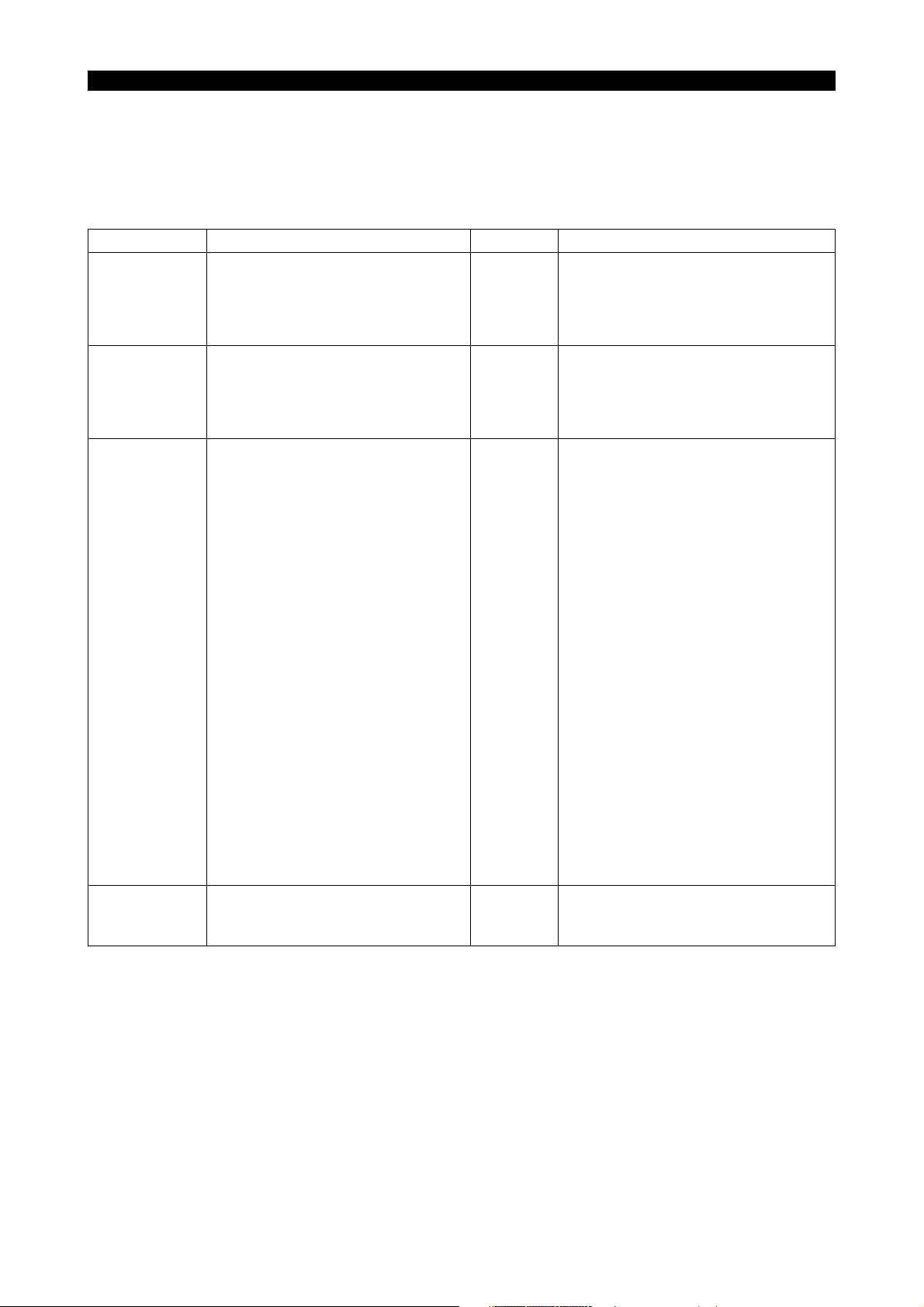
4-4. Programmable Range of Address Characters
5238-E P-5
Address Function
O Program name 0000 to 9999 same as left
N Sequence name 0000 to 9999 same as left
G Preparatory function 0 to 999 same as left
X, Z
C
I, K
D, U, W, H, L
E ±99999.999 mm/rev ±9999.9999 inch/rev
A, B 0 to 99999.999 deg. 0 to 9999.9999 deg.
F
T Tool number
S
SB
M
QA C-axis revolution 1 to 1999 (rev.) same as left
SA C-axis speed 0.001 to 20.000 min
Coordinate values
(linear axis)
Coordinate values
(rotary axis)
Coordinate values of
center of arc
Taper amount and
depth of cut in fixed
thread cutting cycle
Shift amount in
grooving cycle
Automatic
programming
commands
Feedrate per
revolution
Feedrate per minute
Dwell time period 0.01 to 9999.99 sec same as left
Spindle speed
M-tool speed
Miscellaneous
function
±99999.999 mm ±9999.9999 inch
±359.999 deg. ±359.999 deg.
±99999.999 mm ±9999.9999 inch
0 to 99999.999 mm 0 to 9999.9999 inch
0.001 to 99999.999
mm/rev
0.001 to 99999.999
mm/min
6 digits
4 digits
0 to 9999
0 to 9999
0 to 511 same as left
Programmable Range
Metric Inch
0.0001 to 999.9999
inch/rev
0.0001 to 9999.9999
inch/min
same as left
same as left
-1
same as left
Remarks
Alphabetic
characters available
6 digits (with nose R
compensation)
4 digits (without nose
R compensation)
Page 19
SECTION 1 PROGRAM CONFIGURATIONS
5. Mathematical Operation Functions
Mathematical operation functions are used to convey logical operations, arithmetic operations, and
trigonometric functions. A table of the operation symbols is shown below. Operation functions can
be used together with variables to control peripherals or to pass on the results of an operation.
Category Operation Operator Remarks
Exclusive OR EOR 0110 = 1010 EOR 1100 (See *3.)
Logical
operation
Arithmetic
operation
Trigonometric
functions, etc.
Brackets
Logical OR OR 1110 = 1010 OR 1100
Logical AND AND 1000 = 1010 AND 1100
Negation NOT 1010 = NOT 0101
Addition + 8 = 5 + 3
Subtraction - 2 = 5 - 3
Multiplication * 15 = 5 * 3
Division / (slash) 3 = 15/5
Sine SIN 0.5 = SIN [30] (See *4.)
Cosine COS 0.5 = COS [60]
Tangent TAN 1 = TAN [45]
Arctangent (1) ATAN 45 = ATAN [1] (value range: -90 to 90)
Arctangent (2) ATAN2
Square root SQRT 4 = SQRT [16]
Absolute value ABS 3 = ABS [-3]
Decimal to binary conversion BIN
Binary to decimal conversion BCD $25 = BCD [25]
Integer implementation (rounding) ROUND 128 = ROUND [1.2763 x 10²]
Integer implementation (truncation) FIX 127 = FIX [1.2763 x 10²]
Integer implementation (raising) FUP 128 = FUP [1.2763 x 10²]
Unit integer implementation
(rounding)
Unit integer implementation
(truncation)
Unit integer implementation (raising) DFUP 13.265 = DFUP [13.26462] (See *2.)
Remainder MOD 2 = MOD [17, 5]
Opening bracket [ Determines the priority of an operation.
Closing bracket ]
DROUND
DFlX 13.264 = DFlX [13.26462] (See *2.)
30 = ATAN 2 [1,(Square root 3)] (See
*1.)
25 = BIN [$25]
($ represents a hexadecimal number.)
13.265 = DROUND [13.26462] (See
*2.)
(Operations inside the bracket are
performed first.)
5238-E P-6
*1. The value of ATAN2 [b, a] is an argument (range: -180 to 180) of the point that is expressed
by coordinate values (a, b).
*2. In this example, the setting unit is mm.
*3. Blanks must be placed before and after the logical operation symbols (EOR, OR, AND, NOT).
*4. Numbers after function operation symbols (SIN, COS, TAN, etc.) must be enclosed in
brackets "[ ]". ( "a", "b", and "c" are used to indicate the contents of the corresponding bits.)
Page 20
Logical Operations
"a", "b", and "c" represent corresponding bits.
5238-E P-7
SECTION 1 PROGRAM CONFIGURATIONS
• Exclusive OR (EOR) c = a EOR b
If the two corresponding values agree, EOR outputs 0.
If the two values do not agree, EOR outputs 1.
abc
000
011
101
110
• Logical OR (OR) c = a OR b
If both corresponding values are 0, OR outputs 0.
If not, OR outputs 1.
abc
000
011
101
111
LE33013R0300300080001
LE33013R0300300080002
• Logical AND (AND) c = a AND b
If both corresponding values are 1, AND outputs 1.
If not, AND outputs 0.
abc
000
010
100
111
• Negation (NOT) b = NOT a
NOT inverts the value (from 0 to 1, and 1 to 0).
ab
01
10
LE33013R0300300080003
LE33013R0300300080004
Page 21

• Arc tangent (1) (ATAN)
θ = ATAN [b/a]
Arc tangent (2) (ATAN2)
θ = ATAN2 [b/a]
• Integer implementation (ROUND, FIX, FUP)
Converts a specified value into an integer by rounding off, truncating, or raising the number at
the first place to the right of the decimal point.
(in units of microns)
6. Block Delete
5238-E P-8
SECTION 1 PROGRAM CONFIGURATIONS
LE33013R0300300080005
[Function]
This function allows the operator to specify whether specific blocks are executed or ignored in
automatic mode operation.
Blocks preceded by "/" are ignored during automatic mode operation if the BLOCK DELETE switch
on the machine operation panel is set on. If the switch is off, the blocks are executed normally.
When the block skip function is activated, the entire block is ignored.
[Supplement]
• The slash "/" code must be placed at either the start of a block or immediately after a sequence
name (number). If it is placed in another position in a block, it will cause an alarm.
• The slash "/" may not be contained in the program name block.
• Blocks which contain a "/" code are also subject to the sequence search function, regardless of
the BLOCK DELETE switch position.
• The block delete function is not possible during SINGLE BLOCK mode. The succeeding block
is executed, and then the operation stops.
7. Comment Function (CONTROL OUT/IN)
A program may be made easier to understand by using comments in parentheses.
• Comments must be parenthesized to distinguish them from general operation information.
• Comments are also subject to TV and TH checks.
Example:
N100 G00 X200 (FIRST STEP)
Comment
LE33013R0300300100001
Page 22

SECTION 1 PROGRAM CONFIGURATIONS
8. Program Storage Memory Capacity
The NC uses memory to store machining programs. The memory capacity is selectable depending
on the size of the machining program. For execution, a program is transferred from the memory to
the operation buffer (RAM). The capacity of the operation buffer is indicated by one program
capacity.
If the size of the program to be executed is large, it is necessary to expand the one program
capacity. The one program capacity can be selected from 320 m (1049.92 ft), 640 m (2099.84 ft.),
1280 m (4199.68 ft.), to expand program storage capacity.
9. Variable Limits
On execution of a command that specifies axis movement to a target point beyond the variable limit
in the positive direction, the specified target point is replaced with the variable limit in the positive
direction.
For commands specifying axis movement to a target point beyond the variable limit in the negative
direction, axis movement is not executed and an alarm occurs.
5238-E P-9
Page 23
SECTION 1 PROGRAM CONFIGURATIONS
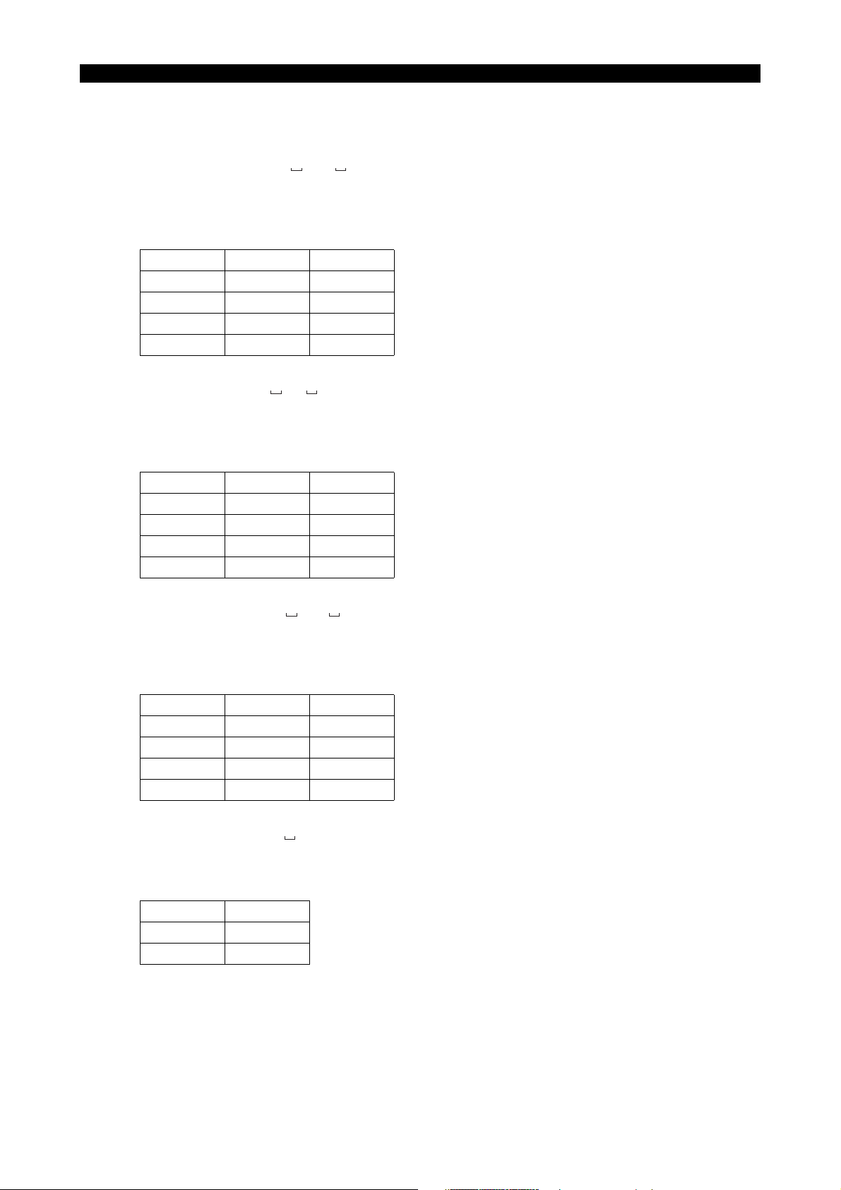
10. Determining Feedrate for Cutting along C-Axis
10-1. Cutting by Controlling the C-axis Only
Although it is possible to machine a workpiece by controlling the C-axis, tool movement distance in
unit time (one minute) differs according to the diameter of the position to be machined because the
feedrate is specified in units of deg/min. This must be taken into consideration when making a
program.
[Memo]
To match the unit of the C-axis feed command with the X- and/or Z-axis command, the feedrate
command (F) should be calculated by converting 360 into 500 mm. This conversion should also be
carried out when only a C-axis command is given.
Example:
90°
200φ
50φ
5238-E P-10
B
90°
A
Axis movement distance along slot A: ⋅⋅⋅⋅⋅⋅⋅⋅⋅⋅⋅⋅⋅π × 50/4 = 39 mm
Axis movement distance along slot B: ⋅⋅⋅⋅⋅⋅⋅⋅⋅⋅⋅⋅⋅π × 200/4 = 156 mm
Therefore, if cutting is carried out at a feedrate of 100 mm per minute,
the feedrate (deg/min) of the C-axis is calculated as follows:
Along slot A(deg/min)⋅⋅⋅⋅⋅⋅⋅⋅⋅⋅⋅⋅⋅100/39 × 90 = 230
Along slot B(deg/min)⋅⋅⋅⋅⋅⋅⋅⋅⋅⋅⋅⋅⋅100/156 × 90 = 58
Convert the unit of feed from "deg/min" into "mm/min".
Slot A: (mm/min)⋅⋅⋅⋅⋅⋅⋅⋅⋅⋅⋅⋅⋅230/360 × 500 = 320 (F320)
Slot B: (mm/min)⋅⋅⋅⋅⋅⋅⋅⋅⋅⋅⋅⋅⋅58/360 × 500 = 80 (F80)
LE33013R0300300130001
Page 24

5238-E P-11
SECTION 1 PROGRAM CONFIGURATIONS
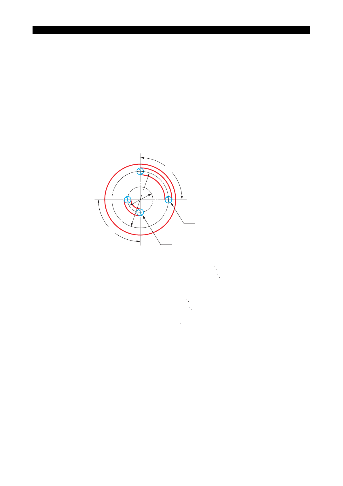
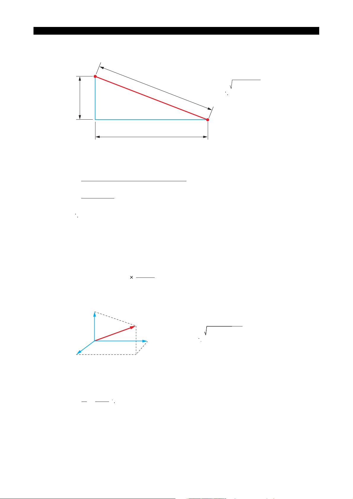
10-2. Cutting by Controlling Both C-axis and Z-axis Simultaneously
Example:
A
90°
Point A coordinate value X = 80
Z = 100
C = 120
B
Point B coordinate value
X = 80
Z = 50
C = 210
LE33013R0300300140001
When cutting the spiral from A to B with a two-flute end mill under the following cutting conditions,
calculate the feedrate of C-axis as explained below:
Cutting
conditions:
Feed per
0.05 mm
tooth
M-tool speed 400 min
-1
Procedure :
1 Calculate the distance between A and B.
A development of the diagram above is indicated below.
L2
90˚
L1
The distance, L
L
1 = 80 × π ×
The distance, L
L
2 = 63
1, along the circumference is:
90
= 63 (mm)
360
2, between A and B is:
2
+ 502 = 80 (mm)
C
50 mm
LE33013R0300300140002
Page 25

5238-E P-12
SECTION 1 PROGRAM CONFIGURATIONS
2 Calculate the cutting time, T, on the basis of the cutting conditions indicated above to feed the
axes along the slot.
2
T=
(Feed per tooth) x (Number of teeth) x (min-1)
=
80
0.05 × 2 × 400
= 2 (min)
L
LE33013R0300300140003
3 Inside the computer, the distance L3 between A and B is calculated in the following manner.
X-axis travel
C-axis travel = 90° ×
= 50 mm
500 mm
360°
= 125 mm
(conversion based on 360° = 500 mm)
Therefore, the distance between A and B is calculated as below:
2
L
3 = 50
+ 125
2
= 135 (mm)
LE33013R0300300140004
4 The feedrate to be specified in the program is approximately calculated as below:
L
3
F =
135
= = 67.5
2
T
LE33013R0300300140005
Specify F67.5 in the program.
10-3. Cutting by Controlling Both C-axis and X-axis Simultaneously
Example:
A
90°
Point A coordinate value X = 80
Z = 100
C = 120
B
Point B coordinate value
X = 40
Z = 100
C = 210
LE33013R0300300150001
• The cutting conditions are the same as used in "Cutting by Controlling Both C-axis and Z-axis
Simultaneously".
Page 26

Procedure :
1 Calculate the distance between A and B.
5238-E P-13
SECTION 1 PROGRAM CONFIGURATIONS
A
402+20
2
2=
L
= 44.7 mm
2
L
40
B
20
LE33013R0300300150002
2 Calculate the cutting time, T, on the basis of the cutting conditions indicated above to feed the
axes along the slot.
2
T =
(Feed per tooth) × (Number of teeth) × (min-1)
=
44.7
0.05 × 2 × 400
= 1.12 min
L
LE33013R0300300150003
3 Inside the computer, the distance L3 between A and B is calculated in the following manner.
X-axis travel = 40 mm
C-axis travel = 90° ×
500 mm
360°
=125 mm
(conversion based on 360° = 500 mm)
Therefore, the distance between A and B is calculated as below:
2
+ 125
2
3 = 40
L
= 131.2 mm
LE33013R0300300150004
4 The feedrate to be specified in the program is approximately calculated as below:
L
131.2
3
F =
= = 117
T
1.12
Specify F117 in the program.
LE33013R0300300150005
Page 27
5238-E P-14
SECTION 1 PROGRAM CONFIGURATIONS
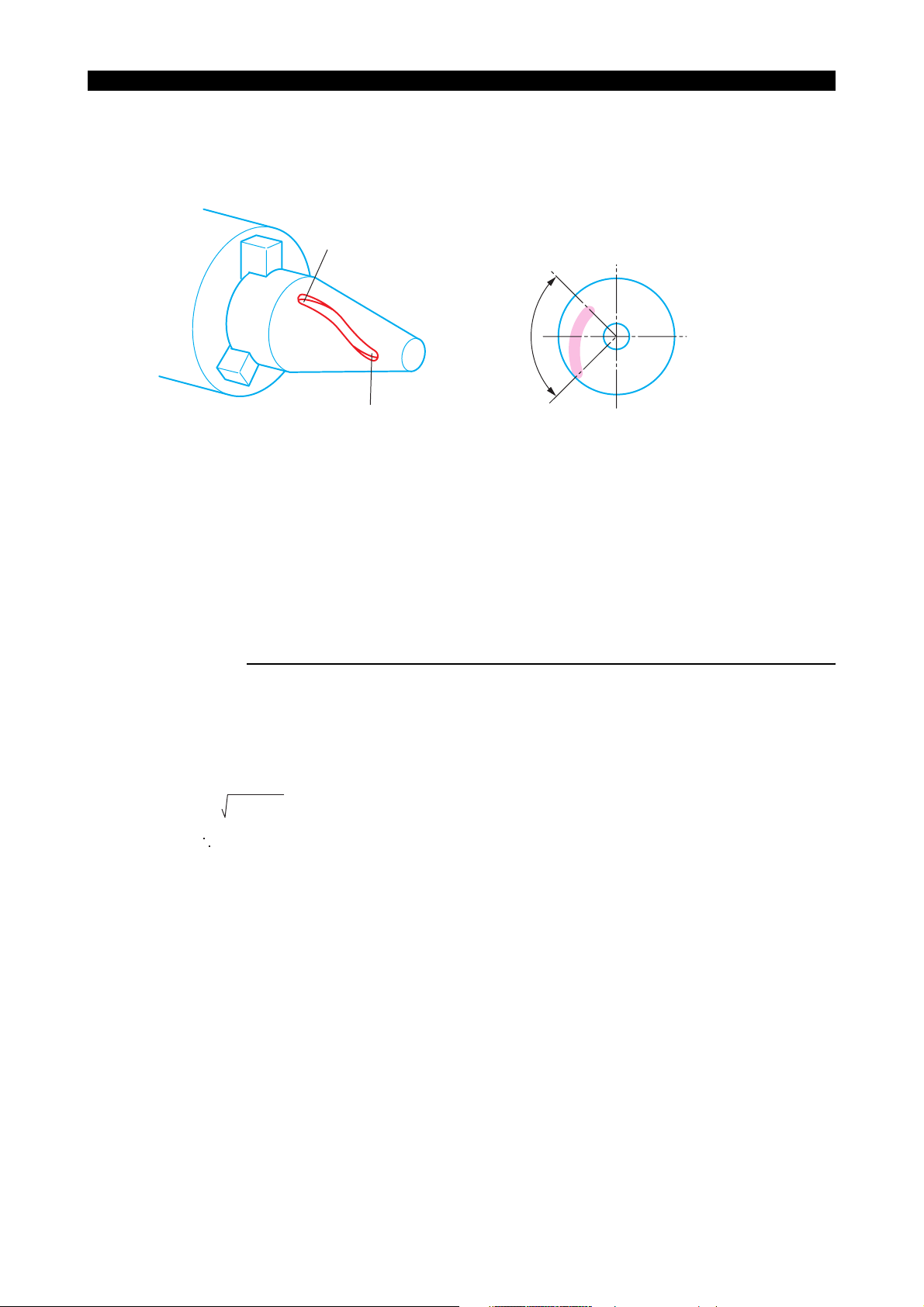
10-4. Cutting by Simultaneous 3-axis Control of X-, Z-, and C-axis
Example:
A
90°
B
Point A coordinate value X = 80
Z = 50
C = 120
Point B coordinate value
X = 40
Z = 100
C = 210
LE33013R0300300160001
• When cutting a slot on a cone as indicated above, simultaneous 3-axis control of the X-, Z-, and
C-axis becomes necessary. The feedrate to be programmed should be calculated in the
following manner. Note that the example below assumes the same cutting conditions as in 11-
2. "Cutting by Controlling Both C-axis and X-axis Simultaneously".
Procedure :
1 First, consider the development of the slot on the C-axis and X-axis. In this case, calculation of
the feedrate is possible in the same manner as in "Cutting by Controlling Both C-axis and X-
axis Simultaneously" .
The C and X-axis travel component, L2, is:
L3 = 402+ 20
= 44.7 mm
2
LE33013R0300300160002
Page 28
SECTION 1 PROGRAM CONFIGURATIONS
2 Calculate the actual distance between A and B from L2 calculated in (1).
A
5238-E P-15
2
L2
4
L
L4 =
44.72 + 50
= 67.1
B
Z-axis travel
LE33013R0300300160003
3 Calculate the cutting time T for distance L4:
4
T=
(Feed per tooth) x (Number of teeth) x (min-1)
=
67.1
0.05 × 2 × 400
L
= 1.68 min
LE33013R0300300160004
4 Inside the computer, distance L5 between A and B is calculated in the following manner.
X-axis travel = 40 mm
Z-axis travel = 50 mm
C-axis travel
= 90
500 mm
365
= 125 mm
(conversion based on 360 = 500 mm)
C
5
L
Z
L5 =
402+502+125
= 140.4 mm
2
X
5 The feedrate to be specified in the program is approximately calculated as below:
L
140.4
5
F =
= = 83.6
T
1.68
Specify F83.6 in the program.
LE33013R0300300160005
LE33013R0300300160006
Page 29

5238-E P-16
SECTION 2 COORDINATE SYSTEMS AND COMMANDS
SECTION 2 COORDINATE SYSTEMS AND COMMANDS
1. Coordinate Systems
1-1. Coordinate Systems and Values
To move the tool to a target position, the reference coordinate system must be set first to define the
target position, and the target position is defined by coordinate values in the set coordinate system.
There are the three types of coordinate system indicated below. A program coordinate system is
used for programming.
• Encoder coordinate system
• Machine coordinate system
• Program coordinate system
1-2. Encoder Coordinate System
An encoder is used to detect the position of a numerically controlled axis. The encoder coordinate
system is established based on the position data output by the encoder.
The position data directly output from the encoder is not displayed on the screen, and this
coordinate system may be disregarded in daily operation.
1-3. Machine Coordinate System
The reference point in the machine is referred to as the machine zero and the coordinate system
which has its origin at the machine zero is called the machine coordinate system. The machine zero
is set for each individual machine using system parameters and it is not necessary to change the
setting after the installation of the machine.
If "0" is set for the encoder zero point offset (system parameter), the machine coordinate system
agrees with the encoder coordinate system.
1-4. Program Coordinate System
The coordinate system used as the reference for program commands is called the program
coordinate system.
The position of the origin of the program coordinate system varies according to the kind of
workpieces to be machined and the origin is set at the required position by setting the zero offset
data. The program coordinate system used for machining a specific kind of workpiece is thus
defined based on the set origin.
Page 30
5238-E P-17
SECTION 2 COORDINATE SYSTEMS AND COMMANDS
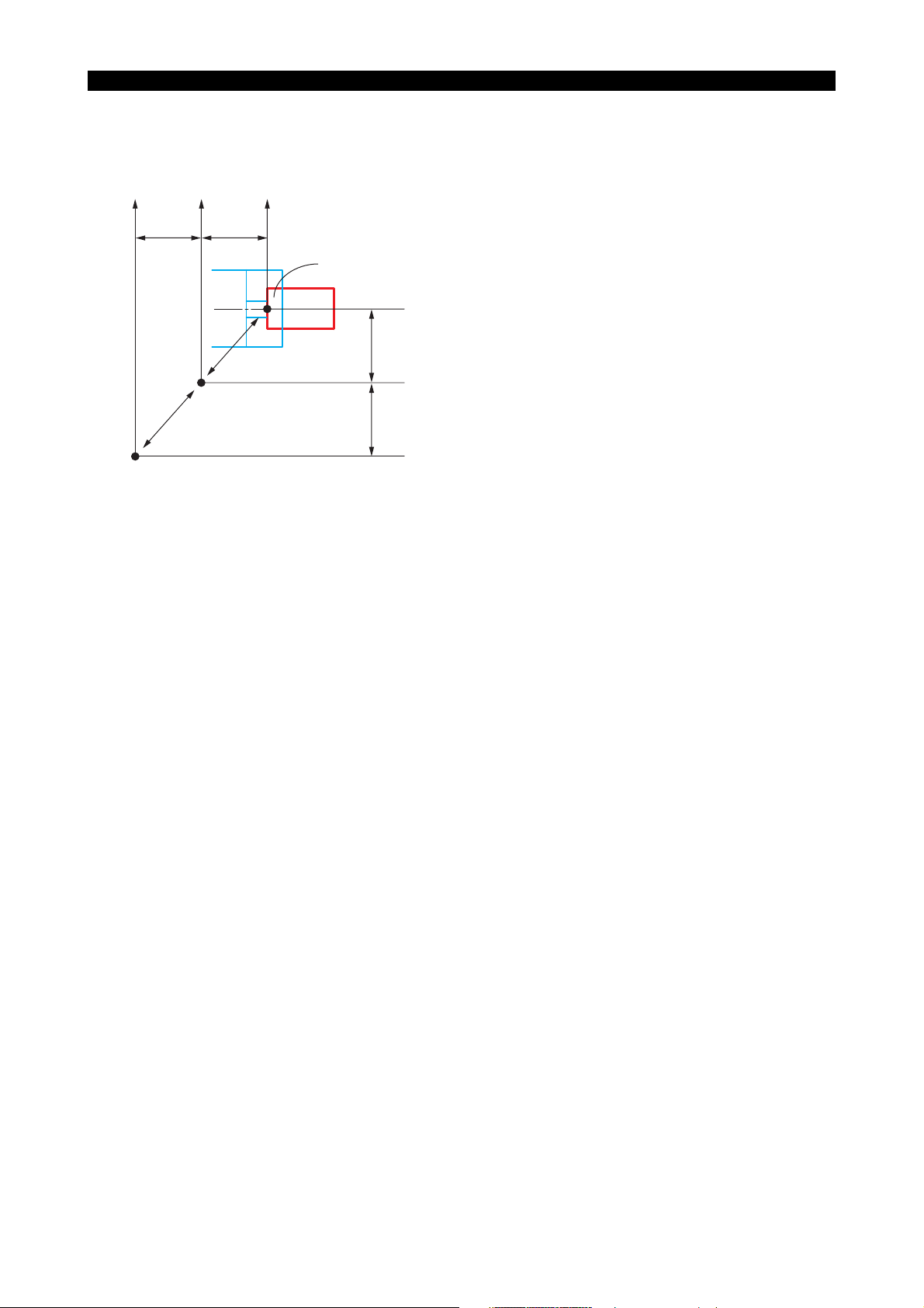
Although the origin of a program coordinate system (program zero) can be set at any position, it is
usually set on the centerline of a workpiece for the X-axis and at the left end face of workpiece for
the Z-axis.
Zd
Zm Zp
Z
1 Z2
Machine coordinate
system
Machine zero
Zero point of encoder
Program zero
Program coordinate
system
Xp
X2
Xm
X1
Xd
Xd, Zd : Output value of position encoder
(0: Zero point of position encoder)
Xm, Zm : Coordinate values in the machine coordinate system
(0: Machine zero)
Xp, Zp : Coordinate values in the program coordinate system
(0: Program zero)
X1, Z1 : Offset amount of position encoder
X1, Z1 : Offset amount of position encoder
LE33013R0300400040001
Page 31

2. Coordinate Commands
g
s
2-1. Controlled Axis
• The following table lists the addresses necessary for axis control.
Address Contents
X
Linear axis
Z
Rotary axis C Rotary axis in a plane orthogonal to Z-axis
• A command used to move an axis consists of an axis address, a direction of movement, and a
target point.
For the designation of a target point, two different methods are available: absolute commands
and incremental commands. With absolute commands, the target point is specified using the
coordinate values in the program coordinate system and with incremental commands the target
point is defined by relative movement distance in reference to the actual position.
For details of absolute and incremental commands, refer to "Absolute and Incremental
commands".
5238-E P-18
SECTION 2 COORDINATE SYSTEMS AND COMMANDS
Controlled axis in the direction parallel to the
workpiece end face
Controlled axis in the direction parallel to the
workpiece longitudinal direction.
• The basic coordinate system is a right-hand orthogonal coordinate system that is fixed on a
workpiece.
Single-saddle NC lathe
X-axis
Z-axis
Infeed direction .... X-axis
Directions of turret motion:
Lon
itudinal direction ... Z-axi
LE33013R0300400050001
Page 32
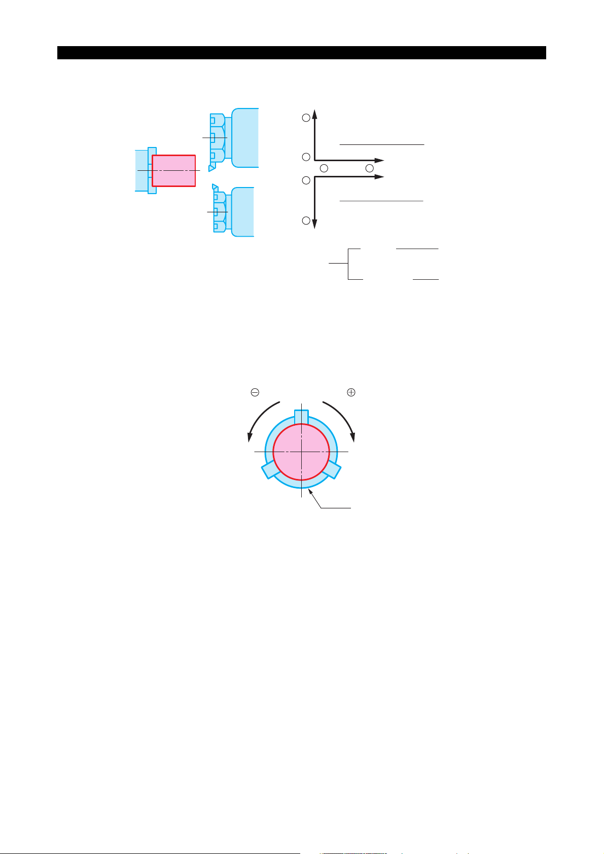
Two-saddle NC lathe
5238-E P-19
SECTION 2 COORDINATE SYSTEMS AND COMMANDS
X-axis
+
Turret A (upper turret)
-
-
-
Turret B (lower turret)
+
X-axis
Z-axis
+
Z-axis
Directions of turret motion:
C-axis coordinate system
Negative direction
M16 M15
C90˚
C90˚
C180˚
Infeed
direction
Longitudinal
direction
Positive direction
C270˚
Chuck
X-axis
Z-axis
LE33013R0300400050002
(Viewed from tailstock)
LE33013R0300400050003
Rightward rotation is defined as positive direction of C-axis movement and is commanded by M15.
M16 is used to specify C-axis movement in the negative direction.
Page 33

2-2. Commands in Inch System
If the inch/metric switchable specification is selected, it is possible to specify dimensions in the inch
unit system. Even if dimensions are specified in the inch system values in a part program, the NC
processes the data on the basis of metric system values. The unit system to be selected for data
input is determined according to the setting of an NC optional parameter (UNIT). The actual unit
system for data input can be checked on the NC optional parameter (UNIT) screen.
[Supplement]
In the conversion from the inch system data to the metric system data, used for internal processing
by the NC, real data values below the minimum input unit are rounded off. Integer data values are
truncated.
2-3. Position of Decimal Point
It is possible to select the unit system of the place of a decimal point. Units of the data available with
the control are shown below and the unit to be employed can be selected by entering a proper
parameter data. Once the unit system of the command data is established, it applies to all
numerical data to be entered, such as MDI operation and zero offset data.
5238-E P-20
SECTION 2 COORDINATE SYSTEMS AND COMMANDS
2-3-1. Metric System
• 1 µm
• 10 µm
• 1 mm
Page 34

SECTION 2 COORDINATE SYSTEMS AND COMMANDS
2-3-2. Inch System (Inch/metric switchable specification):
• 1/10000 inch
• 1 inch
Unit Data Table (Value for data "1")
5238-E P-21
Dimension
Length:
X, Z, I, K, D, H, L,
U, W
Feed (/rev):
F, E
Feed (/min):
A, B, C
Angle:
A, B, C
Time:
F, E
Spindle
-1
min
:
S
Surface speed:
S
Example 1: 1 mm unit system
Commanding:
• 0.001 mm movement of X-axis X0.001
• 10 mm movement of X-axis X10
• 100.00 mm movement of X-axis X100.01
• Feedrate of 0.23456 mm/rev.
The following commands are all handed as X1 mm:
X1
X1.0
X1.00
X1.000
Metric System Inch System
1 µm10 µm 1 mm 1/10000 inch 1 inch
0.001 (mm) 0.1 (mm) 1 (mm) 0.0001 (inch) 1 (inch)
0.001 (mm/rev) 0.01 (mm/rev) 1 (mm/rev)
0.0001 (inch/
rev)
1 (inch/rev)
0.1 (mm/min) 1 (mm/min) 1 (mm/min) 0.01 (inch/min) 1 (inch/min)
0.001 (°)0.01 (°)1 (°) 0.001 (°)1 (°)
0.01 (sec) 0.1 (sec) 1 (sec) 0.01 (sec) 1 (sec)
1 (min-1)1 (min
-1
)1 (min
-1
)1 (min
-1
)1 (min
1 (m/min) 1 (m/min) 1 (m/min) 1 (feet/min) 1 (feet/min)
F0.23456
-1
)
Example 2: 10 mm unit system
Commanding:
• 0.001 mm movement of X-axis X0.1
• 10 mm movement of X-axis X1000
• 100.010 mm movement of X-axis X10001
• Feedrate of 0.23456 mm/rev. F23.456
Example 3: 1 mm unit system
Commanding:
• 0.001 mm movement of X-axis X0.1
• 10 mm movement of X-axis X10000
• 100.010 mm movement of X-axis X100010
Page 35
SECTION 2 COORDINATE SYSTEMS AND COMMANDS
• Feedrate of 0.23456 mm/rev. F234.56
[Supplement]
For F words, numerical data smaller than the selected unit system is effective if it consists of up to
eight digits.
F1.2345678 ⋅⋅⋅⋅⋅⋅⋅⋅⋅⋅Acceptable
F100.000001⋅⋅⋅⋅⋅⋅⋅⋅⋅Alarm (9 digits)
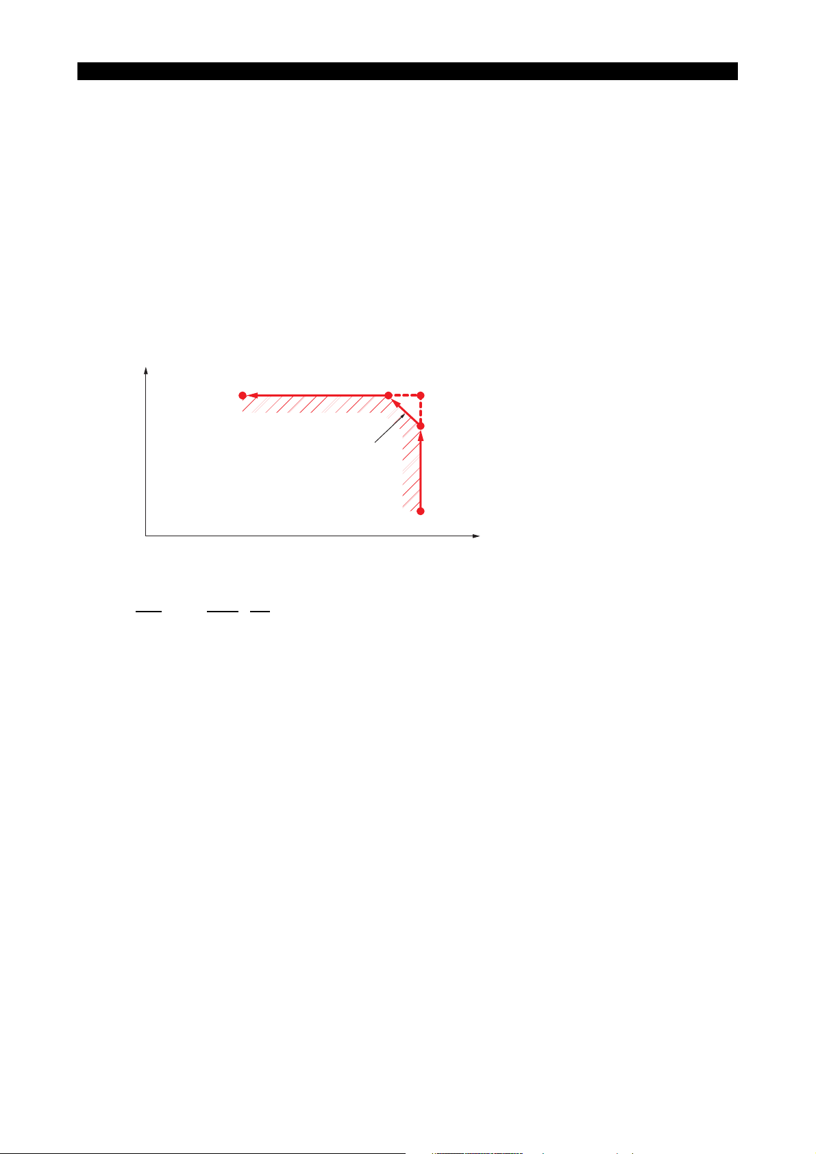
2-4. Absolute and Incremental Commands (G90, G91)
The amount of axis movement can be expressed by either absolute commands or incremental
commands.
(1) Absolute commands
Designated with G90
Commanded values are coordinate values in the program coordinate system.
When the control is reset, it is in the G90 mode.
5238-E P-22
LE33013R0300400090001
(2) Incremental commands
Designated with G91
Commanded values are the travel from the actual position to the target position.
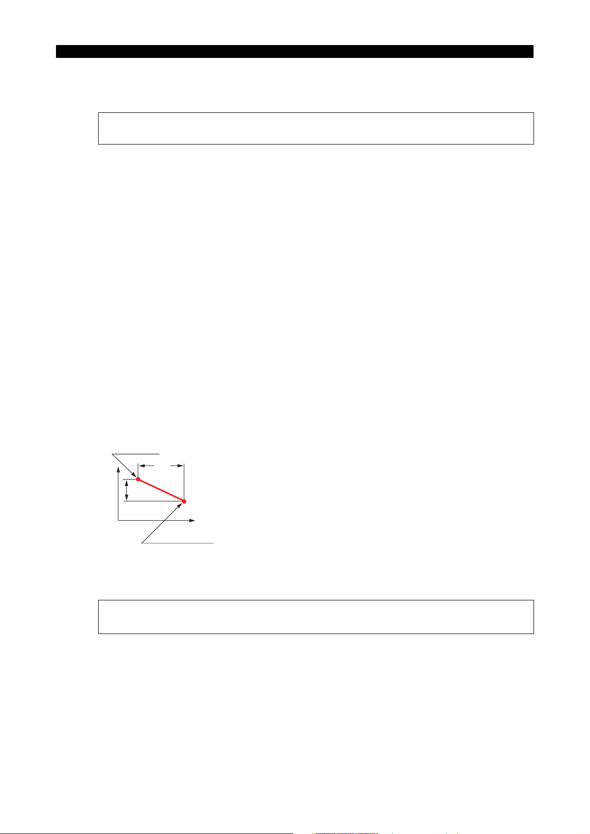
Example:
(Positioning from point (1) to point (2)):
Absolute
(2)
X100 Z50
X
25
100
(1)
X50 Z150
G00 X50 Z150 (1)
X100 Z50 (2)
Incremental
G00 X50 Z150 (1)
*G91 X50 Z-100 (2)
*Designate dimensional differences between points (2) and (1).
[Supplement]
1) In incremental programming, the X word should be expressed as a diameter.
2) It is not permissible to specify both G90 and G91 in the same block.
LE33013R0300400100001
Page 36

SECTION 2 COORDINATE SYSTEMS AND COMMANDS
2-5. Diametric and Radial Commands
In a turning operation, the workpiece is rotated while being is machined. Due to the nature of the
turning operation, the tool cuts a circle with a radius equivalent to the distance from the center of
rotation to the tool nose position. In a program, X-axis commands specify the diameter of the circle
to be cut. If a command of "X100" is specified, for example, the actual position data displayed on
the screen is "100" and the workpiece is machined to a cylinder of 100-mm diameter.
In compound operations, commands in the X-axis direction are specified as diametric values too,
although this type of operation is not a turning operation. In the coordinate conversion mode,
however, the radial values (actual length in an orthogonal coordinate system) must be specified for
both X- and Y-axis commands.
5238-E P-23
Page 37

SECTION 3 MATH FUNCTIONS
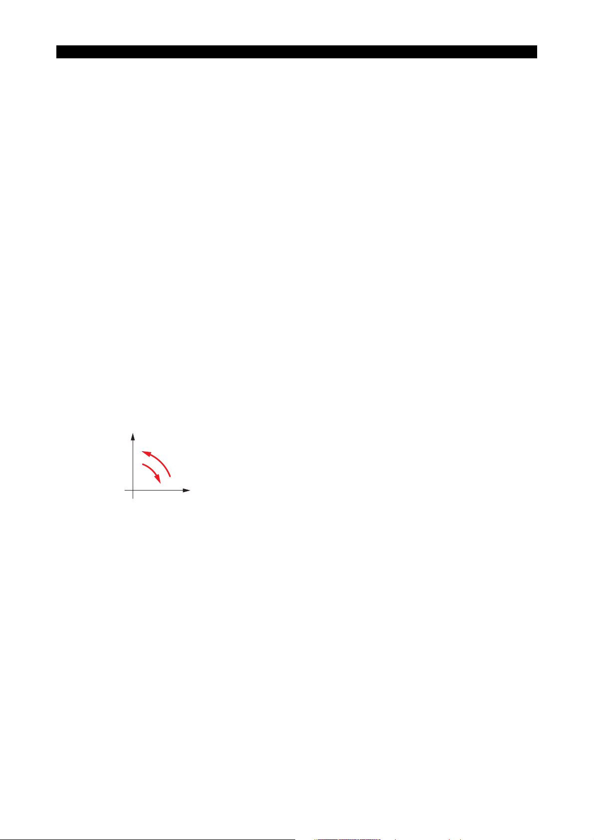
1. Positioning (G00)
[Function]
Each axis moves independently from the actual position to the target position at its own rapid
feedrate. At the start and end of axis movement, it is automatically accelerated and decelerated.
[Programming format]
G00 X__ Z__ C__
X/Z/C : Indicates the target position for positioning operation.
[Details]
• In G00 mode positioning, execution of the commands in the next block begins only after the
positioning at the target position given in the current block is completed.
• Non-linear interpolation mode:
The axes move independently of each other at a rapid feedrate. Therefore, the resultant tool
path is not always a straight line.
5238-E P-24
SECTION 3 MATH FUNCTIONS
X
Actual position
[Supplement]
The rapid feedrates of each axis are set by the machine specifications.
Target position
2. Linear Interpolation (G01)
[Function]
The G01 command specifies the axes to move directly from the current position to the specified
coordinate values at the specified feedrate.
[Programming format]
G01 X__ Z__ C__ F__
Z
LE33013R0300500010001
X, Z, C : Target point (end point)
F:Feedrate.
The specified value remains effective until updated by another value.
Page 38

5238-E P-25
SECTION 3 MATH FUNCTIONS
[Supplement]
1) The feedrate becomes zero when the NC is reset.
2) The feedrate for each axis is indicated below. (Calculate feedrate for X and Z-axes as
incremental values.)
G01 XxZzFf
Calculation of feedrates:
X-axis feedrate FX =
Z-axis feedrate FZ =
where
L3 = x2+z
x, z, f: Command values specified in a program
x
f
L
z
f
L
2
Page 39
3. Circular Interpolation (G02, G03)
[Function]
Circular interpolation can be used to generate a cutting path which follows an arc.
[Programming format]
5238-E P-26
SECTION 3 MATH FUNCTIONS
G02
(G03)
X__ Z__ F__
L__
{}
I__ K__
LE33013R0300500030001
G02 : Direction of rotation : Sets clockwise rotation
G03 : Direction of rotation : Sets counterclockwise rotation
X, Z : G90 mode : Set the end point in the program coordinate system
X, Z : G91 mode : Sets the end point in reference to the starting point
(values should include signs)
I, K : Set the distance of the center of the arc from the starting point (values should include
signs)
L : Sets the radius of the arc
F : Sets the feedrate
[Details]
• The two directions of rotation, clockwise and counterclockwise, are defined when viewing the Z-
X plane from the positive direction of the axis orthogonal to the plane in the right-hand
orthogonal coordinate system.
X
GO3
GO2
Z
LE33013R0300500030002
• The end point of an arc is defined as an absolute value or an incremental value depending on
the G90/G91 selection.
• The center of an arc is expressed by I and K, which correspond to X and Z respectively. That is,
I expresses the X coordinate value and K the Z coordinate value of the center of the arc in
reference to the starting point of the arc.
Page 40

5238-E P-27
SECTION 3 MATH FUNCTIONS
For I and K, signed incremental values are used regardless of the mode, G90 or G91.
X(I)
Z
1
Arc end point
R
X1
φ
Arc start point
G02: Both I and K values are positive
Z
1, X1 indicate the coordinate values
of the arc end point.
Arc center
I
1
K
Z(K)
X(I)
Z
1
Arc end point
φ
X1
R
Arc
center
K
G03: Both I and K values are positive
Z
1, X1 indicate the coordinate values of
the arc end point
Arc start point
I
Z(K)
LE33013R0300500030003
Determining Sign and Numeric Value of I and K Words:
See the figure below. Assume the coordinate system has its origin at the arc start point. Draw a
right-angled triangle taking the segment connecting the arc center and arc start point as the
hypotenuse. The length of side (b), parallel to the Z-axis, is the value of the K word and that of
side (c), parallel to the X-axis, is the value of the I word.
Concerning the sign of these words, when side (b) lies in the positive direction of the assumed
coordinate system, it is taken as a positive value and when it lies in the negative direction, it is
negative. The sign of I words is determined in a similar way. That is, when side (c) lies in the
positive direction of the coordinate system, the I word has a positive value and when it lies in
the negative direction, the I word has a negative value.
Arc start point
K -
ID cutting
I + K -
X-axis
I +
(c)
K +
(a)
Z-axis
(b)
I -
Arc center
I - K -
IOD cutting
K -
K -
I -
I +
K -
LE33013R0300500030004
Page 41
5238-E P-28
SECTION 3 MATH FUNCTIONS
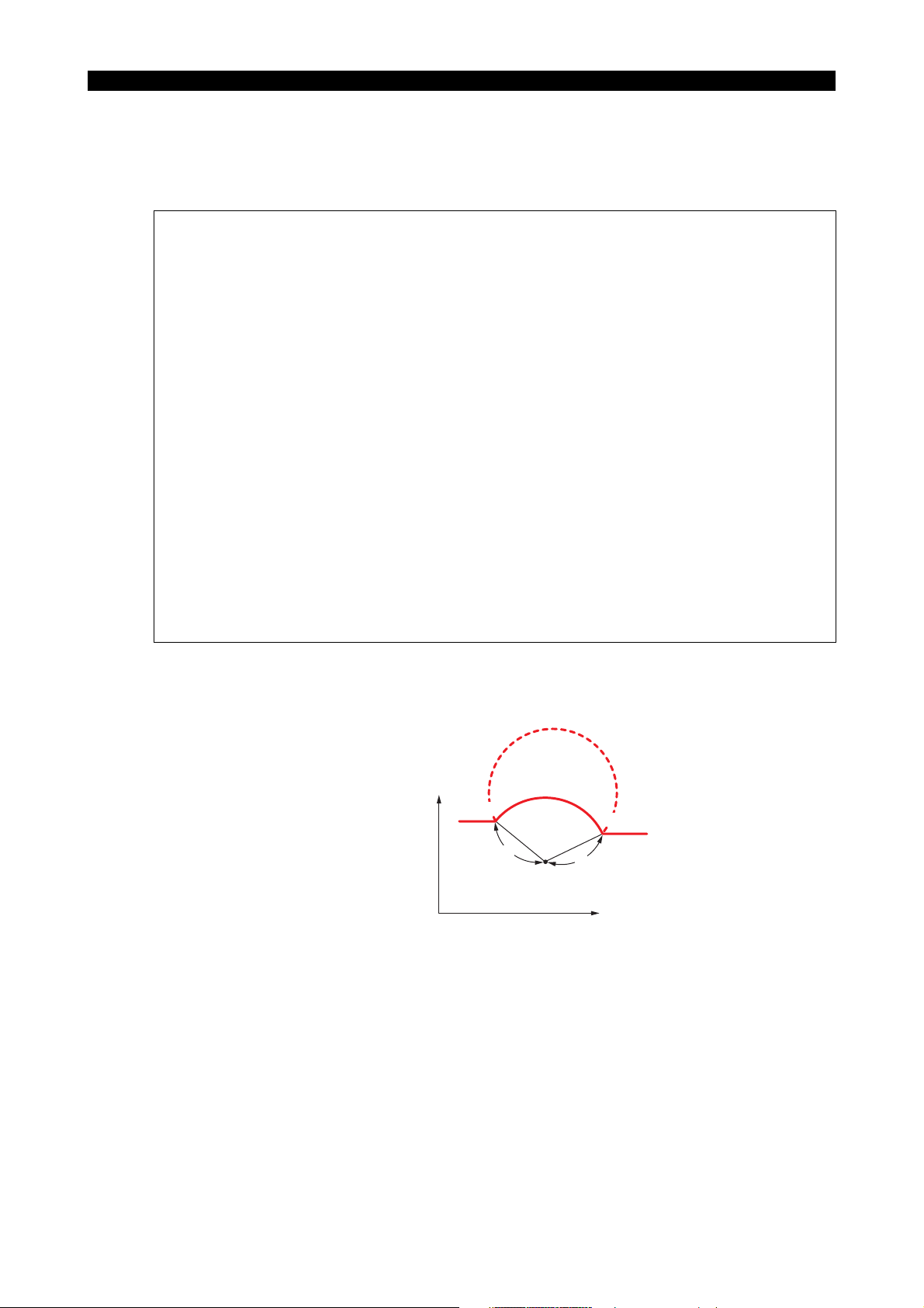
• Direct Radius Command
It is possible to execute circular interpolation by specifying the X and Z coordinate values of the
target point and the radius of the arc instead of using I and K commands.
[Supplement]
• The G code used to call circular interpolation is G02 or G03, as when using I and K.
• The radius of the arc is expressed by an L word which must have a positive value.
• A block containing an L word without a K or I word is an arc radius command.
• When expressing an arc by its radius, the commands must contain both X and Z words.
• If either of them is omitted, an alarm results.
• If an L word is specified in a block containing I and/or K word, an alarm results.
• If the distance from the current position to the target point (end point) is larger than two times
the specified radius, an alarm results since circular interpolation cannot be performed.
• In direct arc command programming, one arc command yields two arcs; one with central angle
less than 180, and another larger than 180. The arc with central angle less than 180 is
selected.
To obtain the arc whose central angle is greater than 180, specify "CALRG" in the block
commanding circular interpolation.
• The direct radius command programming is effective in:
LAP
Tool nose radius compensation mode
Subprograms
• Incremental programming mode (G91)
In direct radius command programming, the control automatically calculates the coordinates of
the center of the arc, I and K, from the programmed radius L and the coordinates of the end
point, X and Z, to perform circular interpolation.
The program for the example in the figure to the right is as follows.
Program:
+X
2
N
(Z2,X2)
N1 G01 X
N2 G03 X2 Z2 Lr
With the commands above,
the arc indicated by a thick solid line is obtained.
To move the tool along the arc indicated by dashed lines, program as follows:
N1 G01 X
N2 G03 CALRG X2 Z2 Lr
1 Z1 F1
1 Z1 F1
r
Center
r
N
1
(Z1,X1)
+Z
• Feedrates
The feedrate during circular interpolation is the feedrate component tangential to the arc.
LE33013R0300500030005
Page 42

5238-E P-29
SECTION 3 MATH FUNCTIONS
[Supplement]
1) If I or K is omitted, I0 or K0 applies.
2) I and K values should be specified as radii.
3) An arc extending into two or more quadrants can be specified by the commands in a single
block.
4) If either X or Z is omitted, circular interpolation is possible within one quadrant.
5) An alarm will be activated if the difference in radius between the start and end point of an arc
is greater than the value set for optional parameter (OTHER FUNCTION 1) No. 6 Allowable
error in circular interpolation.
Page 43
4. Automatic Chamfering
When cutting a workpiece, it is often necessary to chamfer a sharp edge (either straight-line
chamfering (C-chamfering) or rounding). Although such chamfering can be accomplished using
conventional interpolation commands (G01, G02, G03), the automatic chamfering function permits
chamfering to be done with a simple program.
For chamfering at any required angle, the automatic any-angle chamfering function should be used.
To use the automatic chamfering function, set "1" for optional parameter (OTHER FUNCTION 1)
Auto. any-angle chamfering. If the automatic any-angle chamfering function is required, set "anyangle chamfering" for this parameter.
4-1. C-chamfering (G75)
+X
(X120.00, Z50.00)
E
(X120.00, Z115.00)
5C
5238-E P-30
SECTION 3 MATH FUNCTIONS
D
C (X120.00, Z120.00)
B (X110.00, Z120.00)
A (X50.00, Z120.00)
+Z
LE33013R0300500050001
To cut the contour shown above along the points A, B, D and E, program as follows:
G75
G01 X120 L-5 FDD CR
after positioning the cutting tool at point A.
With the commands above, the cutting tool moves from point A to B and then to D, thus
automatically chamfering the corner at 45 with a size of 5 mm.
G75 : Specifies C-chamfering
X120 : X coordinate of Point C
L-5 : Size of chamfered face
The sign is determined by the direction of axis movement;
"+" when the Z-axis (X-axis) moves in the positive direction after X-axis (Z-axis) motion.
"-" when the Z-axis (X-axis) moves in the negative direction after X-axis (Z-axis) motion.
When the coordinates of point E are commanded, the cutting tool moves from Point D to Point E.
[Details]
• G75 is effective only in the G01 mode. If G75 is specified in another mode, it causes an alarm.
• G75 is non-modal and active only in the commanded block.
• If the axis movement dimension specified in the block calling for automatic chamfering (A - C in
the figure above) is smaller than the absolute value of the L word (B - C in the figure above), an
alarm results.
• If the axis movement dimensions specified in the block calling for automatic chamfering are
zero both for X and Z, or if neither the X nor the Z value is zero in such a block, an alarm occurs.
The block calling for the automatic chamfering mode can contain only one dimension word,
either X or Z.
Page 44

• The automatic chamfering program is effective in:
LAP
Tool nose radius compensation mode
[Program example]
90.00
40.00
10.00
60.00
5238-E P-31
SECTION 3 MATH FUNCTIONS
:
:
N101
N102
N103
N104
N105
N106
:
:
G01
G75
G75
G75
G75
5C
160.00φ
X60
X100
X160
Z92
Z60
Z40
Z10
4C
2C
100.00φ
F0.1
F0.05 L3
3C
60.00φ
L-2
L4
L-5
LE33013R0300500050002
Page 45

4-2. Rounding (G76)
5238-E P-32
SECTION 3 MATH FUNCTIONS
+X
(X120.00, Z50.00)
E
(X120.00, Z115.00)
D
C (X120.00, Z120.00)
5R
B (X110.00, Z120.00)
A (X50.00, Z120.00)
+Z
LE33013R0300500060001
To cut the contour shown above along the points A, B, D and E, program as follows:
G76
G01 X120 L-5 FDD CR
after positioning the cutting tool at point A.
With the commands above, the cutting tool moves from point A to B and then to D, thus
automatically rounding the corner to a radius of 5 mm.
G76 : Specifies rounding of a corner
X120 : X coordinate of Point C
L-5 : Radius of rounding circle
The sign is determined by the direction of axis movement;
"+" when the Z-axis (X-axis) moves in the positive direction after the X-axis (Z-axis)
motion.
"-" when the Z-axis (X-axis) moves in the negative direction after the X-axis (Z-axis)
motion.
When the coordinates of point E are commanded, the cutting tool moves from point D to point E.
[Details]
• G76 is effective only in the G01 mode. If G76 is specified in a mode other than G01, an alarm
occurs.
• G76 is non-modal and active only in the commanded block.
• The rounding describes a 1/4 circle with the radius specified by an L word.
• If the axis movement dimension specified in the block calling for automatic chamfering (A - C in
the figure above) is smaller than the absolute value of the L word (B - C in the figure above), an
alarm results.
• If the axis movement dimensions specified in the block calling for automatic chamfering are
zero both for X and Z, or if neither X nor Z value is zero in such a block, an alarm occurs.
The block calling for automatic chamfering mode can contain only one dimension word, either X
or Z.
• The automatic chamfering program is effective in:
LAP
Tool nose radius compensation mode
Page 46

[Program Example]
40.00
10.00
5238-E P-33
SECTION 3 MATH FUNCTIONS
90.00
60.00
5R
4R
N101
N102
N103
N104
N105
N106
G01
G76
G76
G76
G76
160.00φ
X60
X100
X160
Z92
Z60
Z40
Z10
2R
100.00φ
F0.1
F0.05 L3
L-2
L4
L-5
3R
60.00φ
LE33013R0300500060002
Page 47

4-3. Automatic Any-Angle Chamfering
When cutting a workpiece, it is often necessary to chamfer the sharp (C-chamfer or R-chamfer)
corners and edges. If chamfering is required on edges having an angle other than 90°,
programming chamfering using G01, G02 and G03 commands is not easy. This automatic
chamfering function can program chamfering easily.
[Programming Examples]
(1) C-Chamfering (G75)
+X
5238-E P-34
SECTION 3 MATH FUNCTIONS
I (X100, Z72.453)
H (X89.608, Z81.453)
6C
(X60, Z90) F
(X60, Z95)
L6
L5
L6
F∆∆∆
120˚
5C
(X60, Z114)
E
D
6C
C (X60, Z120)
B (X48, Z120)
A (X20, Z120)
+Z
LE33013R0300500070001
N100
N110
N120
N130
N140
G00
G75
G75
G75
G01
A120
J (X100, Z30)
(X68.660, Z87,5) G
⋅
⋅
⋅
⋅
X20
X60
X100
Z120
Z90
Z30
⋅
⋅
⋅
⋅
With the program above, the cutting tool moves from point A to point J in the sequence A, B, D,
E, G, H, I and J, thus accomplishing chamfering of B-D, E-G and H-I.
[Supplement]
Angle commands (A) are designated in reference to the Z-axis.
Page 48
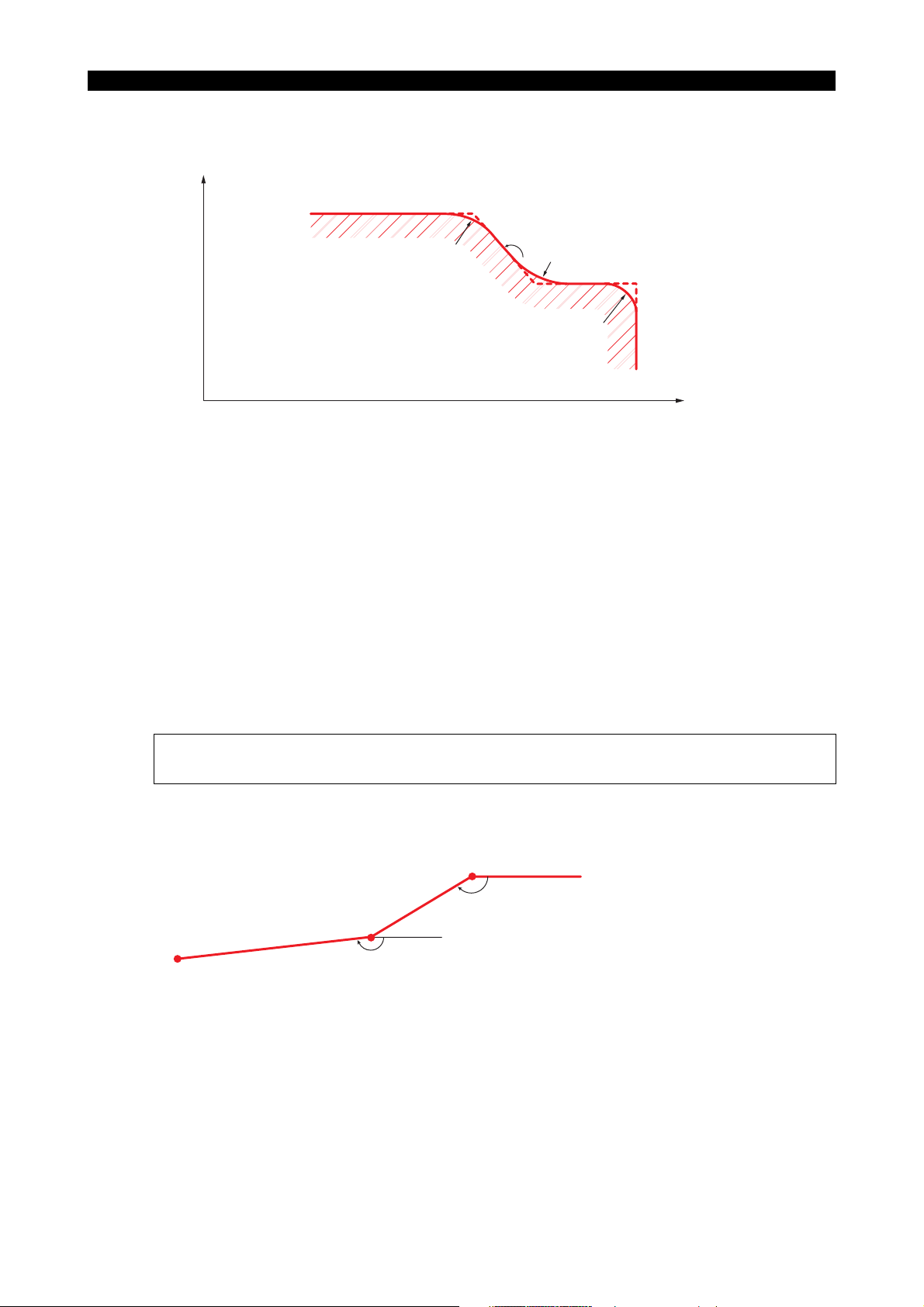
(2) R-Chamfering (G76)
+X
5238-E P-35
SECTION 3 MATH FUNCTIONS
N100
N110
N120
N130
N140
G00
G76
G76
G76
J (X100, Z30)
X20
G01
X60
A120
X100
8R
(X70, Z87.113)
(X60, Z90)
⋅
⋅
⋅
⋅
Z120
L6
Z90
Z30
⋅
⋅
⋅
⋅
L10
L8
I (X100, Z73.884)
H (X92, Z80.762)
120˚
G
F
(X60, Z95.774)
F∆∆
10R
E
(X60, Z114)
D
6R
C (X60, Z120)
B (X48, Z120)
A (X20, Z120)
+Z
LE33013R0300500070002
With the program above, the cutting tool moves from point A to point J in the sequence A, B, D,
E, G, H, I and J, thus accomplishing chamfering of B-D, E-G, and H-I.
[Supplement]
With the C-chamfer function, axis movements in the G00, G01, G34 and G35 modes can be
designated by simply entering an angle command A without X and/or Z coordinate data.
Example:
(X0, Z0)
-150˚
(X1, Z1)
CR
CR
CR
(X2, Z2)
G00
G01X0A-150
X2
-160˚
Z0
Z2F∆A-160
(X1, Z1) should not be designated; it is automatically generated in the NC.
LE33013R0300500070003
Page 49

SECTION 3 MATH FUNCTIONS
[Supplement]
1) Both G75 and G76 are effective only in the G01 mode and if they are designated in a mode
other than G01an alarm occurs.
2) If the axis movement amount is smaller than the chamfering size, an alarm occurs.
3) Chamfering is possible only at corners between two lines. Chamfering at corners between two
arcs, between a line and an arc, or between an arc and a line is impossible. If chamfering at
such corners is attempted, an alarm occurs.
4) The chamfering command is effective both in the LAP and nose radius compensation mode.
5) If only an angle command A is designated in G00, G01, G34, or G35 mode operations, the next
axis movement command must contain A, X and Z commands so that the end point of the line
commanded can be defined. If these commands are not designated and the end point cannot
be defined, then an alarm occurs.
6) If chamfering commands G75 and G76 are designated without axis movement commands X
and Y or if they are designated only with an A command, the control reads the commands in
the next sequence to calculate the point of intersection automatically. Therefore, if the next
sequence does not contain adequate data for this calculation, an alarm occurs.
5. Torque Limit and Torque Skip Function
5238-E P-36
To transfer a workpiece from the first-process chuck to the second-process chuck with multi-process
models*, the end face of the second-process chuck jaws must be pushed against the workpiece for
stable workpiece seating. The torque limit command and the torque skip command are used to
control the torque of the second-process chuck feed servomotor and to push the workpiece with the
optimal thrust.
* Multi-process models include sub spindle models, opposing two-spindle models, etc.
5-1. Torque Limit Command (G29)
[Function]
Prior to workpiece transfer, designate the torque limit command to control the maximum torque of
the second-process chuck feed servomotor.
[Program Format]
G29 P D __
(Designate an axis to be fed: Z or W, for D.)
[Details]
• The torque limit value is set as a percentage, taking the rated torque of the axis feed
servomotor as 100%.
• The maximum torque limit value is set for optional parameter (OTHER FUNCTION 2).
5-2. Torque Limit Cancel Command (G28)
[Function]
The torque limit cancel command cancels the maximum torque limit designated with G29.
When this command is designated, the axis feed motor can output its maximum output torque.
[Programming format]
G28
Page 50
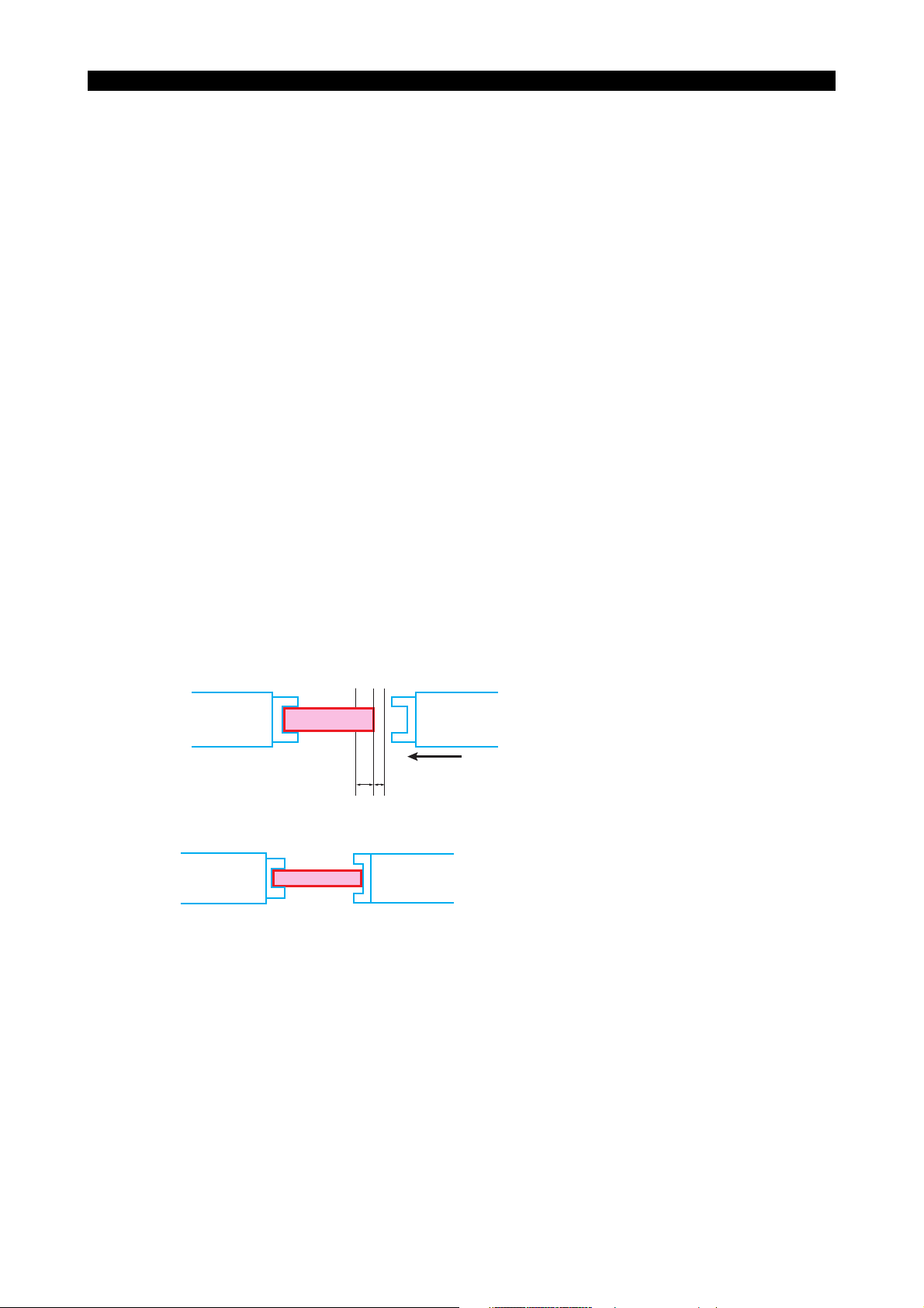
5-3. Torque Skip Command (G22)
[Programming format]
G22 Z__ D__ L__ F__ PZ =__
Z : Target point (mm)
D : Distance between the target point and the approaching point as an incremental value
(mm)
L : Distance between the target point and the virtual approaching point as an incremental
value (mm)
F : Feedrate (mm/min or mm/rev)
PZ : Preset torque value (%)
[Details]
• For the target point and the set torque value, designate the axis to be fed..
• An alarm (alarm A 1220) occurs if the preset torque value is not reached when the second-
process chuck has moved to the virtual approaching point.
• Designate a value equal to or smaller than "2.5 m/min (8.20 fpm)" for F.
5238-E P-37
SECTION 3 MATH FUNCTIONS
• Before setting a value for PZ, check the actual motor torque value** at axis feed at the feedrate
designated by F, and set a value for PZ which is larger than the actual torque value by 10%.
** Check the RLOAD value displayed on the axis data page of the CHECK DATA screen.
If the preset torque value is too small, it is reached during approaching motion, resulting in an
occurrence of alarm 1219.
First-process chuck Second-process chuck
The explanation here is for a case in which a
workpiece is transferred from the first-process
chuck to the second-process chuck.
LD
Z
1. The second-process chuck approaches the
workpiece at feedrate F.
2. The feedrate is reduced to 1/5 of F at the
approaching point (Z - D) point).
3. The second-process chuck contacts the
workpiece at target point Z.
The servomotor is controlled so that the
second-process chuck is kept pushed
against the workpiece.
4. When the motor torque reaches the preset value,
the NC recognizes workpiece seating to be
complete, and the next program block is executed.
LE33013R0300500110001
Feedrate F → F/5
Z:Target point
D : Distance between the target point and the approaching point as an incremental value
L : Distance between the target point and the virtual approaching point as an incremental value
Page 51

5-4. Parameter Setting
(1) Torque skip torque monitoring delay time
If motor torque monitoring is started at the start of torque skip feed designated by G22, the
preset torque value could, in some cases, be exceeded on starting up the motor.
To avoid this, set the torque monitoring delay time t for a parameter. Motor torque is not
monitored for the time duration set for t.
Motor torque
Set torque value
5238-E P-38
SECTION 3 MATH FUNCTIONS
Time
t
Torque monitor OFF
Torque monitor ON
Optional parameter (OTHER FUNCTION 2)
Setting unit : 10 (ms)
Setting range : 0 to 9999
Initial setting : 0
(2) Upper limit for torque skip torque limit
The upper limit for the P command value in the G29 block can be set.
Optional parameter (OTHER FUNCTION 2)
Setting unit : 1 (%)
Setting range : 1 to 100
Initial setting : 0
LE33013R0300500120001
Page 52
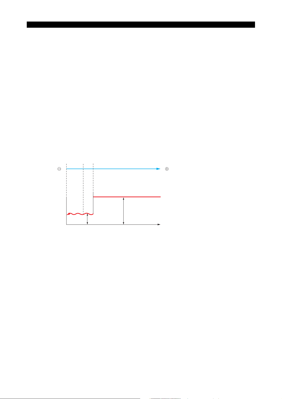
5-5. Program Example
This is a program example for transferring a workpiece to the sub spindle chuck.
:
:
G29 PW=30⋅⋅⋅⋅⋅⋅Limits the maximum torque of the sub spindle feed motor
(W-axis motor). (30 %)
G94 G22 W50 D5 L10 F1000 PW=25⋅⋅⋅⋅⋅⋅Pushes the sub spindle chuck against
the workpiece end face by torque skip
G29 PW=5⋅⋅⋅⋅⋅⋅Lowers the W-axis motor torque.
M248⋅⋅⋅⋅⋅⋅Sub spindle chuck close
M84⋅⋅⋅⋅⋅⋅Main spindle chuck open
G28⋅⋅⋅⋅⋅⋅Cancels W-axis torque limit.
G90 G00 W300⋅⋅⋅⋅⋅⋅Returns the W-axis to the retract position at the rapid feedrate.
:
:
5238-E P-39
SECTION 3 MATH FUNCTIONS
W
Feedrate
60 50 45
W
1000 mm/mim
200 mm/mim
t
LE33013R0300500130001
Page 53

5238-E P-40
SECTION 4 PREPARATORY FUNCTIONS
SECTION 4 PREPARATORY FUNCTIONS
G codes are used to specify particular functions which are to be executed in individual blocks. Every G code
consists of the address "G" plus a 3-digit number (00 to 399)
• Effective G Code Ranges
One-shot : A one-shot G code is effective only in a specified block
and is automatically canceled when program execution
moves to the next block.
Modal : A modal G code is effective until it is changed to another
G code in the same group.
LE33013R0300600010001
• Special G Codes
The mnemonic codes of subprogram calls (G101 through GI 10, for instance) and branch instructions are
called special G codes. Every special G code must be specified at the beginning of a block, not part way
through a block. Note, however, that a "/" (block delete) and a sequence name may be placed before a
special G code.
1. Dwell (G04)
[Function]
If dwell is specified, execution of the next block is suspended for the specified length of time after the
completion of the preceding block.
[Programming format]
G04 F__
F : Specify the length of time for which the execution of a program is suspended.
The unit of command values is determined by the selected programming unit system.
For details, refer to the optional parameter (unit system).
The maximum allowable length of a dwell period is 9999.99 seconds.
Page 54

SECTION 4 PREPARATORY FUNCTIONS
2. Zero Shift/Max. Spindle Speed Set (G50)
2-1. Zero Shift
[Function]
With the G50 code, zero offset value is automatically calculated and zero setting is carried out
according to the calculated value.
This feature is effective when cutting a workpiece on which the same contour is repeated.
[Programming format]
G50 X__ Z__ C__
X/Z/C : Specify the coordinate value to be taken as the actual position data after zero shift.
[Details]
For the present X- and Z-axis position, the coordinate value specified following G50 are assigned.
[Program]
N004
G00
X0
Z0
N005
G50
X1
Z1
N006
G00
X2
Z2
5238-E P-41
LE33013R0300600030001
With the program above, the axes are positioned to the coordinate point (X0, Z0) by the commands
in block N004 first. When the commands in N005 are executed, the coordinate system is reestablished so that (X0, Z0), where the axes have been positioned, now has the coordinate values
(X1, Z1) which are specified following G50.
This program shifts the origin of the coordinate system:
X = X0 - X1
Z = Z0 - Z1
Provided X0 = 100 mm and X1 = 200 mm, zero offset amount is calculated as;
100 - 200 = -100 mm
This amount can be checked on the screen.
Dimension words in sequences N006 and after that are all referenced to the origin newly
established by the commands in N005.
[Supplement]
1) Axes not specified in the block containing G50 are not subject to zero offset.
2) G50 is non-modal and active only in the programmed block. (Zero offset is calculated only in
the G50 block. All dimension words after that block are referenced to the shifted new origin.)
3) When the control is reset, all zero set data are cleared and the initial zero offset data become
effective.
4) No tool offset number entry is allowed in the block containing the G50 code.
Page 55
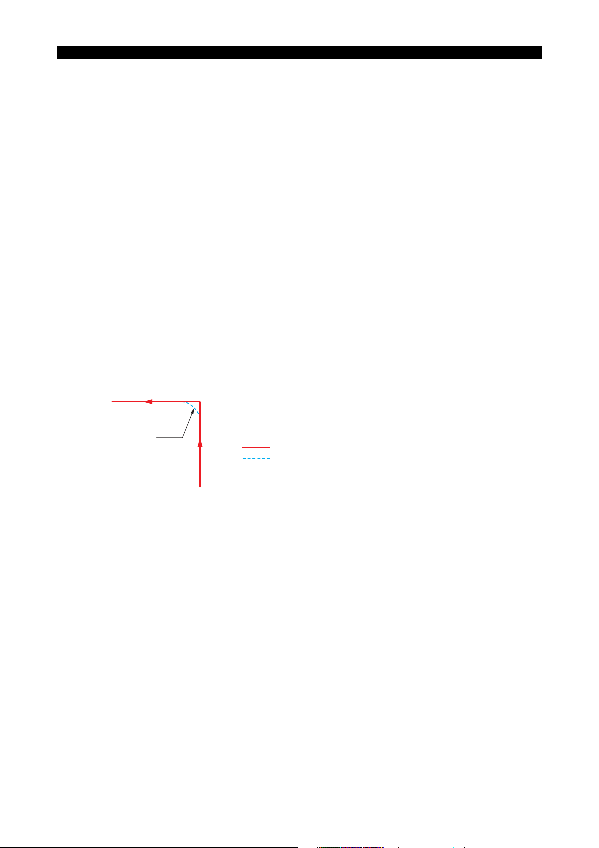
2-2. Max. Spindle Speed Set
[Function]
Sometimes the spindle speed must be clamped at a certain speed due to the restrictions on the
allowable speed of a chuck, influence of centrifugal force on workpiece gripping force, imbalance of
a workpiece, or other factors. This feature allows a maximum spindle speed to be set in such cases.
[Programming format]
G50 S__
S : Specify the maximum spindle speed.
[Details]
Once set, the specified speed remains effective until another spindle speed is specified.
3. Droop Control (G64, G65)
[Function]
The axis movements of the machine are controlled by a servo system in which the axis moves to
eliminate the lag (termed DIFF or droop) between the actual tool position and the commanded
coordinate.
Due to existence of DIFF (servo error), the actual path does not precisely agree with the
commanded tool path when cutting a sharp corner, as illustrated below:
The Droop Corner Control Function is provided to eliminate or reduce such path tracing error to
acceptable amounts by stopping the generation of functions (pulses) at the corner until the DIFF
reaches the preset permissible droop amount.
5238-E P-42
SECTION 4 PREPARATORY FUNCTIONS
Droop
Programmed tool path
Actual tool path
LE33013R0300600050001
[Programming format]
• Droop corner control OFF command
G64
(The control is placed in the G64 mode when G64 is turned ON.)
• Droop corner control ON command
G65
[Details]
• With G65 presented, axis movement commands in G00, G01, G02, G03, G31, G32, G33, G34,
and G35 mode are completed after the DIFF amount becomes smaller than the permissible
droop amount.
• The permissible droop amount can be set within a range from 0 to 1.000 mm for a user
parameter at the NC operation panel.
Page 56

4. Feed Per Revolution (G95)
[Function]
Specify G95 to control tool movement (feedrate) in terms of "distance per spindle revolution" for
turning operations.
[Programming format]
G95 F__
F : Specify movement distance per spindle revolution.
The unit of setting is determined according to the setting for the optional parameter (UNIT)
[Details]
• The allowable maximum feedrate depends on the machine specifications.
• On turning on the power, and after reset, the feed per revolution mode is selected.
5. Feed Per Minute (G94)
[Function]
Specify G94 to control tool movement (feedrate) in terms of "distance per minute" for turning
operations.
[Programming format]
G94 F__
F : Specify tool movement distance per minute.
The unit of setting is determined according to the setting for the optional parameter (UNIT)
5238-E P-43
SECTION 4 PREPARATORY FUNCTIONS
[Details]
• The allowable maximum feedrate depends on the machine specifications.
Page 57

SECTION 4 PREPARATORY FUNCTIONS
6. Constant Speed Control (G96/G97)
[Function]
When the constant speed cutting function is selected, cutting at a constant cutting speed is possible.
This feature can reduce cutting time and also assure stable finish in end face cutting operations.
Constant Speed Cutting Command
[Programming format]
G96 S__
S : Set the cutting speed (setting unit: m/min)
Canceling Constant Speed Cutting
[Programming format]
G97 S__
S : Set the spindle speed to be used after canceling the constant speed cutting mode.
[Program Example]
5238-E P-44
N ΟΟΟ G96 S100⋅⋅⋅⋅⋅⋅⋅All cutting following this block is executed at a cutting speed of 100 m/min.
-1
N ΟΟΟ G97 S500⋅⋅⋅⋅⋅⋅⋅After this block, cutting is carried out at a spindle speed of 500 min
.
LE33013R0300600080001
[Supplement]
1) If the spindle speed exceeds the maximum or minimum speed allowed within the range
selected by an M code while in the constant speed cutting mode, it is fixed at the allowed
maximum or minimum speed automatically; the LIMIT indication light on the operation panel
goes on.
2) If the X-axis is moved a large distance at the rapid traverse rate while in the constant speed
cutting mode, for example from the turret indexing position toward the workpiece or vice versa,
there will be sudden changes in the rotational speed which, depending on the chucking method,
could be dangerous.
Therefore, the constant speed cutting mode must be cancelled before commanding positioning
of the cutting tool near the workpiece, return of the tool to the turret indexing position, or any
other operation that causes large X-axis travel.
3) A block containing G96 or G97 must contain an S word.
4) Thread cutting programs cannot be executed in the G96 constant speed cutting mode.
5) To activate the constant speed cutting mode on turret B, specify G111 with G96. To restore
the constant speed cutting mode to turret A, specify G110.
6) To execute the commands over two blocks continuously with control in the constant speed
cutting mode without waiting for the spindle speed arrived signal, specify M61. To cancel this,
specify M60.
Page 58

5238-E P-45
SECTION 5 S, T, AND M FUNCTIONS
SECTION 5 S, T, AND M FUNCTIONS
This section describes the S, SB, T, and M codes that specify the necessary machine operations other than
axis movement commands.
S : Spindle speed
SB : Spindle speed of M-tool spindle
T : Tool number, tool offset number, tool nose radius compensation number
M : Miscellaneous function to control machine operation
One block can contain: one S code, one T code, and eight M codes.
1. S Functions (Spindle Functions)
[Function]
By specifying number following address S, spindle speed can be specified.
[Programming format]
S__
[Details]
• S command range: 0 to 65535
• If there is an S command and an axis move command in the same block, the S command is
executed first and then the axis move command is executed.
• The S command will not be canceled when the NC is reset, however, it will be set to 0 when the
power supply is turned off.
• To rotate the spindle, the S command must be specified in a block that precedes the block
containing the spindle start command or in the same block.
[Supplement]
1) For a machine equipped with the transmission gears, the required gear range should be
selected with the corresponding M code.
2) Spindle rotation (forward, reverse) and stop are specified by M codes.
2. SB Code Function
[Function]
M-tool spindle speed is specified using address SB.
[Programming format]
SB = __
f an address consisting of two or more characters is used, an equal symbol must be entered before
a numeric value.
• SB command range: 0 to 65535
• M-tool spindle rotation (forward, reverse) and stop are specified by M codes.
• The SB command will not be canceled when the NC is reset, however, it will be set to 0 when
the power supply is turned off.
Page 59

• To rotate the M-tool spindle, the SB command must be specified in a block that precedes the
block containing the M-tool spindle start command or in the same block.
[Supplement]
1) For the machine equipped with the transmission gears for driving the M-tool spindle, the
required gear range should be selected by a corresponding M code.
2) M-tool spindle rotation (forward, reverse) and stop are specified by M codes.
3. T Functions (Tool Functions)
[Function]
By specifying a 4-digit number (NC without tool nose radius compensation function) or a 6-digit
number (NC with tool nose radius compensation function) following address T, tool number, tool
offset number, and tool nose radius compensation number are indicated.
[Programming format]
TΟΟ∆∆
ΟΟ : Tool nose radius compensation number
∆∆ : Tool number (00 to 99, assuming maximum number of turret stations)
: Tool offset number
5238-E P-46
SECTION 5 S, T, AND M FUNCTIONS
LE33013R0300700040001
The setting ranges for nose radius compensation numbers and tool compensation numbers are as
follows:
(1) For offset 32-set specification
• Tool offset number: 00 to 32
• Tool nose radius compensation number: 00 to 32
(if tool nose radius compensation function is supported.)
(2) For offset 64-set specification
• Tool offset number: 00 to 64
• Tool nose radius compensation number: 00 to 64
(if tool nose radius compensation function is supported.)
(3) For offset 96-set specification
• Tool offset number: 00 to 96
• Tool nose radius compensation number: 00 to 96
(if tool nose radius compensation function is supported.)
[Details]
If there is a T command and an axis move command in the same block, the T command is executed
first and then the axis move command is executed.
[Supplement]
The construction of the turret and its direction of rotation (forward, reverse, shorter-path) vary
according to the machine specifications.
Page 60

4. M Functions (Auxiliary Functions)
[Function]
The M codes are used for miscellaneous ON/OFF control and sequence control of the machine
operation such as spindle start/stop and operation stop at the end of program. The programmable
range for M codes is from 0 to 511.
[Examples of M codes]
The M codes listed below are processed as special functions.
For details on those M codes not listed here, refer to APPENDIX 3. "List of M Codes".
(1) M00 (program stop)
After the execution of M00, the program stops. If the NC is started in this program stop state,
the program restarts.
(2) M01 (optional stop)
When M01 is executed when the optional stop switch on the machine operation panel is ON,
the program stops. If the NC is started in this optional stop state, the program restarts.
(3) M02, M30 (end of program)
These M codes indicate the end of a program.
When M02 or M30 is executed, the main program ends and reset processing is executed. The
program is rewound its start. (In the case of a schedule program, execution of M02 or M30 in
the main program does not reset the NC.)
5238-E P-47
SECTION 5 S, T, AND M FUNCTIONS
(4) M03, M04, M05 (spindle CW, CCW, stop)
These M codes control spindle rotation and stop; spindle CW (M03), spindle CCW (M04), and
spindle stop (M05).
(5) M12, M13, M14 (rotary tool CW, CCW, stop)
These M codes control rotary tool rotation and stop for the turning center; rotary tool stop (M12),
rotary tool CW (M13), rotary tool CCW (M14).
(6) M15, M16 (C-axis positioning direction)
These M codes control the C-axis rotation direction for positioning for the turning center; C-axis
positioning in the positive direction (M15), C-axis positioning in the negative direction (M16).
(7) M19 (spindle orientation)
This controls spindle orientation.
(8) M20, M21 (tailstock barrier ON, OFF)
These M codes set and cancel the tailstock barrier which generates an alarm if the tool enters
the area defined by the barrier; tailstock barrier ON (M21), tailstock barrier OFF (M20).
(9) M22, M23 (chamfering ON, OFF for thread cutting)
These M codes set and cancel chamfering for thread cutting; chamfering ON (M23), chamfering
OFF (M22).
(10) M24, M25 (chuck barrier ON, OFF)
These M codes set and cancel the chuck barrier which generates an alarm if the tool enters the
area defined by the barrier; chuck barrier ON (M25), chuck barrier OFF (M24).
(11) M26, M27 (thread pitch axis X-axis, Z-axis)
These M codes specify the effective thread pitch axis for conventional thread cutting cycles; Xaxis pitch command (M27), Z-axis pitch command (M26).
Page 61

5238-E P-48
SECTION 5 S, T, AND M FUNCTIONS
(12) M32, M33, M34 (thread cutting mode; straight, zigzag, straight (reversed))
These M codes are used to specify the thread cutting mode in the compound fixed cycle and
LAP; M32 for infeed along one side of the thread face to be cut (straight), M33 for zigzag infeed,
and M34 for straight infeed along the opposite thread face from the one in the M32 mode
(straight (reversed)).
(13) M40, M41, M42, M43, M44 (spindle drive gear range; neutral, gear 1, gear 2, gear 3, gear 4)
These M codes are used to select the spindle drive gear range; neutral (M40), gear 1 (M41),
gear 2 (M42), gear 3 (M43), and gear 4 (M44).
(14) M48, M49 (spindle speed override ignore)
When the spindle speed override ignore function is valid, the spindle speed override rate is
fixed at 100% regardless of the setting of the spindle override switch. The spindle speed
override ignore function is canceled by specifying the cancel M code, resetting the CNC, or
changing the operation mode.
< M codes >
Spindle speed override ignore⋅⋅⋅⋅⋅⋅⋅⋅⋅⋅⋅⋅⋅⋅⋅⋅⋅⋅⋅⋅⋅⋅⋅⋅⋅⋅⋅⋅⋅ M49
Spindle speed override ignore cancel⋅⋅⋅⋅⋅⋅⋅⋅⋅⋅⋅⋅⋅⋅⋅⋅⋅M48
LE33013R0300700050001
(15) M55, M56 (tailstock spindle retract, advance)
These M codes specify tailstock retract/advance operation.
(16) M60, M61 (fixed surface speed arrival ignore OFF, ON)
These M codes are used to specify whether or not a program with constant surface speed
control is executed continuously without waiting for attainment of the specified surface speed;
M61 specifies advance to the next block without waiting for attainment of the specified surface
speed, and M60 specifies advance to the next block only after attainment of the specified
surface speed.
(17) M63 (spindle rotation answer signal ignore)
The M codes relating to spindle control (M03, M04, M05, M19, M40 - M44) and S command are
executed at the same time with axis move commands specified in the same block.
(18) M73, M74, M75 (thread cutting pattern 1, 2, 3)
In multi-machining fixed cycle and thread cutting cycle in LAP, the cutting pattern (infeed
pattern) is specified by these M codes. M73 for pattern 1, M74 for pattern 2, and M75 for
pattern 3.
(19) M83, M84 (chuck clamp, unclamp)
Regardless of the chuck clamp direction (I.D. or O.D.), the M code used to specify the clamping
of a workpiece is always M83.
(20) M85 (no return to the start point after the completion of LAP roughing cycle)
In LAP4, a roughing cycle is called by G85 or G86. When this M code is specified, the cutting
tool does not return to the reference point of the cycle after the completion of the called
roughing cycle, and the next block is executed continuously.
(21) M86, M87 (turret clockwise rotation ON, OFF)
These M codes are used to specify whether or not the turret rotation direction is fixed in the
clockwise direction; M86 specifies turret clockwise rotation ON, and M87 specifies turret
clockwise rotation OFF.
Page 62

5238-E P-49
SECTION 5 S, T, AND M FUNCTIONS
(22) M109, M110 (C-axis connection ON, OFF)
These M codes are used to select the spindle control mode for the multiple-process machining
specification models. By specifying M110, the spindle is controlled in the C-axis control mode
and by specifying M109, the control mode is returned to the spindle control mode. Note that
M110 must be specified in a block without other commands.
(23) M124, M125 (STM time-over check ON, OFF)
These M codes are used to determine whether or not an alarm is generated if the counted STM
execution cycle time exceeds the parameter-set time; M124 specifies that the alarm is
generated, and M125 specifies that the alarm is not generated.
(24) M136 (shape definition for compound fixed cycle)
This M code is used to specify the shape for the compound fixed cycles provided for the
multiple-process specification models. After the execution of the compound fixed cycle, the
cutting tool returns to the start point of rapid traverse.
(25) M140 (tapping cycle rotary tool fixed speed arrived answer signal ignore)
This M code is used to ignore the tapping cycle rotary tool fixed speed arrived answer signal; by
specifying this M code, the timing difference between the output of rotary tool fixed speed
arrived answer signal and the start of cutting feed can be zeroed. Note that this M code is
available with the multiple-process specification models.
(26) M141, M146, M147 (C-axis clamp used/not-used selection, C-axis unclamp, C-axis clamp)
For a compound fixed cycle carried out under light load on multiple-process specification
models, it is not necessary to clamp the C-axis to carry out cutting. In such a case, M141 is
used to select the "C-axis clamp is not used" state, thereby reducing cutting time.
M146 and M147 are used to control C-axis clamping and unclamping; M146 for C-axis clamp
and M147 for C-axis unclamp.
(27) M156, M157 (center work interlock ON, OFF)
When center work is selected, operation is possible only when the tailstock spindle is at the
predetermined position. For chuck work, the tailstock spindle must be at the retract end
position. These M codes are used to cancel the interlock function.
[Supplement]
• When the power supply is turned off or after the NC is reset, the NC is in the M156 state.
• The state selected by these M codes is effective only for MDI and automatic operation modes.
(28) M160, M161 (feedrate override fixed at 100% OFF, ON)
These M codes are used to specify whether or not the setting of the feedrate override dial,
when other than 100%, is valid; in the M161 mode, if the setting of the feedrate override dial on
the machine operation panel is in other than 100%, the setting is ignored and the feedrate
commands are executed assuming a setting of 100%, and in the M160 mode, the setting of the
feedrate override dial is valid.
(29) M162, M163 (rotary tool spindle override fixed at 100% OFF, ON)
These M codes are used to specify whether or not the setting of the rotary tool spindle speed
override dial, when other than 100%, is valid; in the M163 mode, if the setting of the rotary tool
spindle speed override dial on the machine operation panel is in other than 100%, the setting is
ignored and the rotary tool spindle speed commands are executed assuming the setting of
100%, and in the M162 mode, the setting of the rotary tool spindle speed override dial is valid.
Page 63

5238-E P-50
SECTION 5 S, T, AND M FUNCTIONS
(30) M164, M165 (slide hold and single block ignore OFF, ON)
These M codes are used to specify whether or not the slide hold ON and single block ON
statuses, set by the switches on the machine operation panel, are valid; in the M165 mode, if
the slide hold or single block function is set ON with the corresponding switch on the machine
operation panel, these functions are made invalid, and in the M166 mode, if the slide hold or
single block function is set ON by the corresponding switch on the machine operation panel,
these functions are made valid.
(31) M166, M167 (tailstock spindle advance/retract interlock during spindle rotation ON, OFF)
To ensure safety, the tailstock spindle cannot normally be advanced or retracted while the
spindle is rotating. However, tailstock spindle operation is permitted even while the spindle is
rotating by turning OFF the interlock.
[Supplement]
• When the power supply is turned off or after the NC is reset, the NC is in the M166 state.
• The state selected by these M codes is effective only for MDI and automatic operation modes.
(32) M184, M185 (chuck open/close interlock ON, OFF)
To ensure safety, the chuck cannot normally be opened or closed while the spindle is rotating.
However, chuck open/close operation is permitted even while the spindle is rotating by turning
OFF the interlock.
[Supplement]
• When the power supply is turned off or after the NC is reset, the NC is in the M184 state.
• The state selected by these M codes is effective only for MDI and automatic operation modes.
• The state selected by these M codes is effective only when the door is closed.
• The chuck interlock OFF state is effective for chuck clamp/unclamp operation specified by M
codes or external commands and it is not effective for the operation using the foot pedal and
pushbutton switches.
(33) M193, M194 (thread cutting phase matching control OFF, ON)
In the M194 mode, the phase offset amount at the thread cutting start point is calculated and
compensation is carried out at the start and end points. After the completion of the thread
cutting cycle, the M194 mode must be canceled by specifying M193 in a block without other
commands.
(34) M195, M196 (thread cutting phase matching move amount valid OFF, ON)
By specifying M196 in the block preceding the block which contains the commands to stop a
program for thread cutting phase matching, the amount of manual axis movement done in
phase matching is stored. M196 must be specified in a block without other commands.
After the completion of manual axis movement for phase matching, the M196 mode must be
canceled by specifying M195 in a block without other commands.
(35) M197 (clearing thread cutting phase matching amount)
This M code is used to clear the amount which is stored as the manual axis movement amount
for phase matching.
(36) M211, M212, M213, M214 (key-way cycle cutting mode; uni-directional, zigzag, specified
cutting amount, equally-divided cutting amount)
M211 and M212 are used to specify the cutting direction in the key-way cutting cycle; unidirectional cutting (M211) and zigzag cutting (M212).
M213 and M214 are used to specify the infeed pattern; M213 specifies the specified cutting
amount and M214 specifies the equally-divided cutting amount.
Page 64

(37) M241, M242 (rotary tool spindle speed range, LOW, HIGH)
These M codes are used to select the spindle speed range of the rotary tool spindle for the
multiple-process specification models; low-speed range (M241), high-speed range (M242).
5. M-tool Spindle Commands
5-1. Programming Format
%
N001
N002
N003
N004
G00
G094
G01
X1000
X∆∆∆
X(Z)∆∆∆
Program block for rotary tool maching
Z1000
Z∆∆∆
F∆
C∆∆∆
5238-E P-51
SECTION 5 S, T, AND M FUNCTIONS
T∆∆
M110
M15(M16)
M147 M13 (M14)
SB=∆∆∆∆
N100
N101
N102
N103
G00
X(Z)∆∆∆
X1000 Z1000 M146
M109
M02
LE33013R0300700060001
[Details]
• M110 must be programmed in a block without other commands.
• It is advisable to limit the direction of rotation of the C-axis to either of the two directions, M15 or
M16, for better positioning accuracy.
• M110 and M147 cannot be reset or canceled even when the control system is reset. To cancel
them, specify M109 and M146, respectively.
• If commands relating to M-tools are specified while the C-axis is not engaged, an alarm occurs.
An alarm does not occur if the M-tool spindle interlock (optional) is designated.
Page 65

5-2. M Codes Used for C-axis Operation
The following codes are necessary for programming C-axis movements.
Code Details
Used to designate the spindle to be controlled in the C-axis control mode.
M110
M109 Used for switchover from the C-axis control mode to the spindle control mode.
M147 Used to clamp the C-axis.
M146
M141 C-axis clamp ineffective (compound fixed cycle mode)
M15
M16
QA =
When programming C-axis commands, first specify M110 in a block without other
commands.
Used to unclamp the C-axis.
The control system automatically selects the M146 mode when the power is
turned on.
Program M146 before starting C-axis rotation.
Used to rotate the C-axis in the positive
direction.
Used to rotate the C-axis in the negative
direction.
Used to specify the number of C-axis revolutions.
For example, QA=5 rotates C-axis five times.
5238-E P-52
SECTION 5 S, T, AND M FUNCTIONS
M16 M15
Chuck end face
* When the NC is reset, it is placed in the M15 mode.
[Example of Program]
C90
120φ
C180
Program
zero
80
C270
100
ø15 mm hole
C0
Tool No. : T0101
Tool : ø15 mm drill
Command
point
SB = 400min
-1
LE33013R0300700070002
Page 66
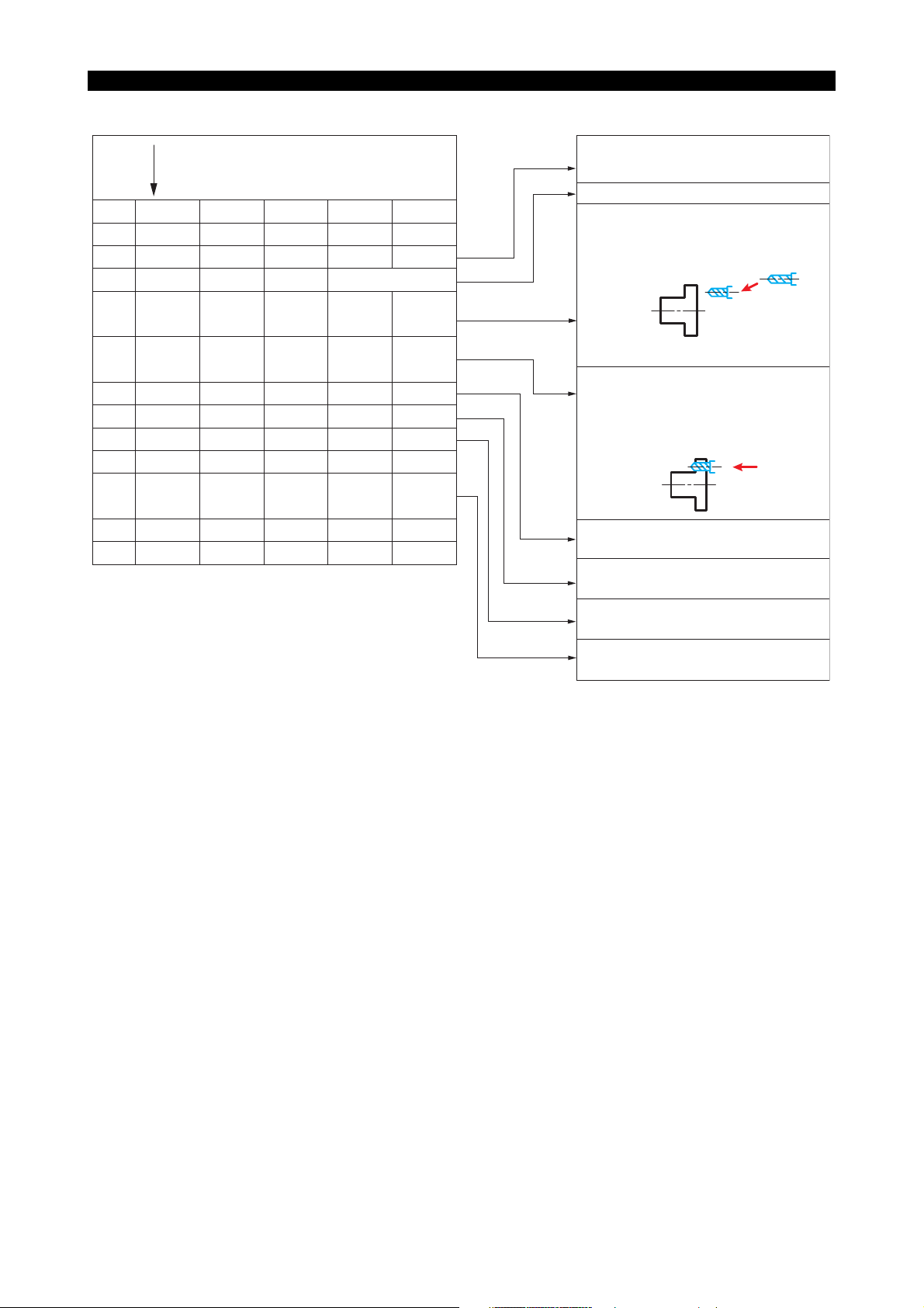
SECTION 5 S, T, AND M FUNCTIONS
To drill two 15 mm dia. holes, create a program as indicated below:
5238-E P-53
N099
N100
N101
N102
N103
N104
N105
N106
N107
N108
N109
N110
N111
Continued from turning operation program
G00
G94
G01
G00
G01
G00
G095
X1000
X120
X1000
Z1000
Z102
Z75
Z102
Z75
Z102
Z1000
M15
C90
F40
C270
M05
M01
M110
T0101
SB=400
M13
M147
M146
M147
M12
M146
M109
M02
Designates the spindle as the C-axis.
Indexes C-axis in the positive direction.
The spindle indexes at the 90° position
in positive direction and the drill is
positioned near the workpiece surface
at the rapid feedrate.
(G00)
Feedrate in mm/min mode is selected.
The drill starts rotation at 400 min-1{rpm}
in the leftward direction.
After thespindle is clamped, 15 mm dia.
hole is drilled at a feedrate of
40 mm/min.
(G01)
The drill returns to the commanded
point at the rapid feedrate.
The spindle is indexed at the 270
position after it is unclamped.
The second hole is drilled after the
spindle is clamped.
The M-tool stops and the turret returns to
the turret index position.
°
LE33013R0300700070003
• Calculate the feedrate (mm/min) for drilling with the equation below:
Feedrate (mm/min) = Tool speed (rpm) x Feedrate (mm/rev)
Therefore, when the tool speed is 400 min-1{rpm} and the feedrate is 0.1 mm/rev, the feedrate
(mm/min) is calculated as:
F = 400 x 0.1 = 40 mm/min
• When an end mill is used, its feedrate (mm/min) is calculated with the following equation:
Feedrate (mm/min) = Tool speed (rpm)
Feed (mm/blade)
Number of end mill blades
• Assuming an end mill with four blades (flutes) is used at 300 min-1{rpm} and a feedrate of 0.05
mm/blade, the feedrate (mm/min) is
F = 300 x 0.05 x 4 = 60 mm/min
Page 67

6. STM Time Over Check Function
The duration of S, T, M cycle time is measured and if the measured time exceeds the parameter-set
cycle time, an alarm occurs.
6-1. Check ON Conditions
• The check function is set effective or ineffective according to the setting for a machine
parameter.
• The check function is turned on and off using the following M codes.
M124 : STM time over check start
M125 : STM time over check end
6-2. S, T, M Cycle Time Setting
Set, for the machine parameter, the allowable limit of cycle time when executing an S, T, and M
codes.
5238-E P-54
SECTION 5 S, T, AND M FUNCTIONS
• Parameter setting
Units : 0.1 seconds
Maximum
setting
: 600 seconds
Page 68

6-3. Timing Chart Example
(1) Parameter setting
Parameter: ON STM time over check start
Parameter: OFF STM time over check end
STM operation in progress
Parameter
Time over check
5238-E P-55
SECTION 5 S, T, AND M FUNCTIONS
Parameter-set
cycle time
(2) M Codes
M124 : STM time over check start
M125 : STM time over check end
Part program in progress
M124
M125
Alarm B
LE33013R0300700110001
Parameter-set
cycle time
Time over check
Alarm B
LE33013R0300700110002
Page 69

5238-E P-56
p
SECTION 6 OFFSET FUNCTION
SECTION 6 OFFSET FUNCTION
1. Tool Nose Radius Compensation Function (G40, G41, G42)
1-1. General Description
The tool tip point radius of most cutting tools used in turning operation is the cause of
inconsistencies between the designated tool paths and the actually finished workpiece contour.
With the tool radius compensation function, such geometric error is automatically compensated for
by simple programming.
1-2. Tool Nose Radius Compensation for Turning Operations
Tool Offset and Nose Radius Compensation
In turning operations, various types and different shapes of tools are used to finish one workpiece.
ID cutting tools, OD cutting tools, rough cut tools, finish cut tools, drills, etc. Accordingly, the tool
nose radius compensation function has to be activated simultaneously with the tool offset function.
Nose radius
compensation
Position
com
ensation
LE33013R0300800020001
Tool Nose Radius Compensation at Discontinuous Point
B'
B
A'
A
Point A in the figure above constitutes a discontinuous point and an angle less than 180°. By using
the tool nose radius compensation function, the tool path shown above can be generated by simply
entering the coordinates of points A and B.
LE33013R0300800020002
Page 70

1-3. Compensation Operation
Geometrical Cutting Error due to Tool Nose Radius
If cutting along paths A-B-C-D-E in the figure below is intended but the tool nose radius
compensation function is not activated, the shaded portions will remain uncut and cause
geometrical errors. This is because the tool setting is made to locate the imaginary cutting point P
at the datum point and trace the programmed path as controlled by NC commands. However, the
actual cutting tip point is not precisely located on that datum point because of the tool nose radius
and this produces geometrical errors.
The tool nose radius compensation function automatically compensates for the inconsistency
between the designated and actual tool paths caused by the tool nose radius (see the figure below).
Nose radius
Point P
5238-E P-57
SECTION 6 OFFSET FUNCTION
Tool Setting Point
E
D
Tool Path and Resulting Error Without Tool Nose Radius Compensation
C
BA
LE33013R0300800030001
Page 71

5238-E P-58
e
SECTION 6 OFFSET FUNCTION
Compensation Movement
With the tool nose radius compensation function activated, the error in the tool path described in (1)
is compensated for as shown below to finish the workpiece to the dimensions specified in a
program.
F
E
D
C
B'
B
Tool Path with Tool Nose Radius Compensation
A
LE33013R0300800030002
Nose radius compensation during LAP mode
To use the tool nose radius compensation function in the LAP mode, programs for the respective
turrets must contain the tool nose radius compensation programs independently as shown below.
LAP shape designation
Nose radius
compensation
G81
G42
G40
G80
Possible
G42
G81
G40
G80
Not possible
LAP cycle call
G42
Possible
G40
G85
G42
Not possibl
G85
G40
LE33013R0300800030003
Page 72
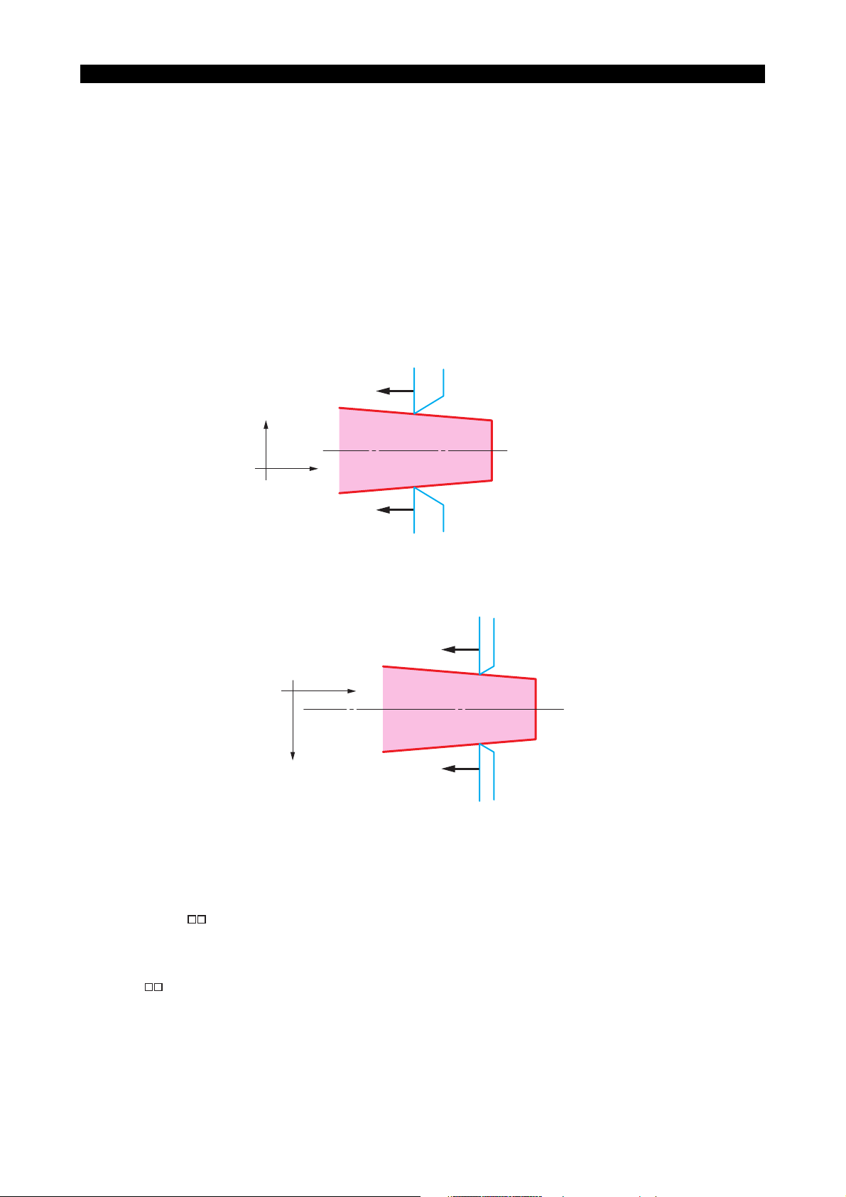
SECTION 6 OFFSET FUNCTION
1-4. Nose Radius Compensation Commands (G, T Codes)
The programming commands - G and T codes, used to activate the tool nose radius compensation
function, are detailed in this section.
G Codes
G40 : Used to cancel the tool nose radius compensation mode.
G41 : Tool nose radius compensation - Left
Used when the tool moves on the left side of the workpiece.
G42 : Tool nose radius compensation - Right
Used when the tool moves on the right side of the workpiece.
The term indicating the side of the workpiece, right or left, is determined according to the direction in
which the tool is advancing.
G42 : Right of workpiece
X+
5238-E P-59
Z+
G41 : Left of workpiece
LE33013R0300800040001
Since G41 and G42 codes are selected to agree with the coordinate system (right-hand system) the
machine employs, they should be selected as below for lathes which have a coordinate system in
which the positive direction of the X-axis is directed toward the operator.
G41
Z+
X+
G42
LE33013R0300800040002
T Codes
Six numerical characters following address character "T" specify the nose radius compensation
number, tool number, and tool offset number.
TΟΟ∆∆
ΟΟ: Tool nose radius compensation number
∆∆: Tool number
: Tool offset number
LE33013R0300800040003
Page 73

5238-E P-60
SECTION 6 OFFSET FUNCTION
[Supplement]
To change the tool offset during the execution of tool nose radius compensation, designate the tool
nose radius compensation number and the tool number.
Example:
G01
G03
G01
G03
Xa Za T010101
Xb Zb
Zd T110111
Xd Zd KI
Entry of only the tool offset No. (T01 or T11) in G code command (1) or (2) will cancel the nose
radius compensation amount.
1-5. Data Display
The screen display during nose radius compensation is described here.
(1) Actual Position
Actual position data is displayed on the screen as with the conventional control system.
However, the data displayed on the screen may be different from the programmed data
because of the tool nose radius compensation.
......
1)
......
2)
LE33013R0300800040004
C
B′ B
Command point
Point indicated on display unit
A
LE33013R0300800050001
(2) Alarm Display
If an alarm relating to the tool nose radius compensation function occurs, the ALARM light
under STATUS DISPLAY goes on and the screen displays the message indicating the alarm
contents.
Page 74

1-6. Buffer Operation
The NC usually operates in the 3-buffer mode. While the positioning command from point A to point
B is being executed, the positioning point data of points C, D and E are read and stored in the buffer.
This is called the 3-buffer function.
When the tool nose radius function is activated, the target point E is calculated from straight lines
DE and EF. This means that the data in the block four blocks ahead the current target point are read
if the tool nose radius compensation function is active.
Fourth positioning point
F
5238-E P-61
SECTION 6 OFFSET FUNCTION
Reading point
(four blocks ahead)
E
Second positioning point
D
Third positioning point
Data in Buffer
C
B
Immediate target point
Present tool position
A
LE33013R0300800060001
1-7. Path of Tool Nose "R" Center in Tool Nose Radius Compensation
Mode
To execute the motion shown below in the following program in the tool nose radius compensation
mode, the path of the tool nose R center is obtained as follows:
N1
G42
X1
Z1
N2
N3
N4
G41
X2
X3
X4
Z2
Z3
Z4
N5
N5′ N4′
X+
X5
Z+
Z5
N4
N3′ N2′
N3 N2
N1
N1′
LE33013R0300800070001
Page 75

5238-E P-62
SECTION 6 OFFSET FUNCTION
(1) To obtain point N2’ when the center of the tool nose R is at point N1’, proceed as follows:
• Draw a straight line parallel to the direction of tool advance, N1 - N2, offset in the specified
direction, (to the right since G42 is specified), by the tool nose radius compensation
amount. This yields the straight line passing N1’ and N2’.
• Draw a straight line parallel to the direction of tool advance, N2 - N3, offset in the specified
direction, (to the right of or above N2 - N3 since G42 dominates the compensation mode)
by the tool nose radius compensation amount. This yields the straight line passing N2’ and
N3’.
• The nose R center for the commanded point N2’ is the point of intersection of these two
straight lines.
The center of the tool nose radius advances from point N1’ to N2’.
(2) To obtain point N3’:
• Draw a straight line parallel to the direction of tool advance, N2 - N3, offset in the specified
direction, (to the right of or above N2 - N3 since G42 dominates the compensation mode),
by the tool nose radius compensation amount. This yields the straight line passing N2’ and
N3’.
• Draw a straight line parallel to the direction of tool advance, N3 - N4, offset in the specified
direction, (to the left since G41 is specified), by the tool nose radius compensation amount.
This yields the straight line passing N3’ and N4’.
• The nose R center for commanded point N3 is the point of intersection of these two straight
lines.
The center of the tool nose radius advances from point N2’ to point N3’.
(3) To obtain point N4’:
Follow the same procedure indicated above using points N3, N4 and N5.
1-8. Tool Nose Radius Compensation Programming
1-8-1. G41 and G42
The G41 and G42 codes are used to call out the tool nose radius compensation mode. Since the
uses of these G codes are often confused in programming a part, this section deals with their
particular differences.
G41 : This tool nose radius compensation code is used when the cutting tool moves on the left
side of the workpiece in relation to its direction of advance.
G42 : This tool nose radius compensation code is used when the cutting tool moves on the right
side of the workpiece in terms of its direction of advance.
Page 76

SECTION 6 OFFSET FUNCTION
1-8-2. Behavior on Entering Tool Nose Radius Compensation Mode
5238-E P-63
N0
N1
N2 G01 X2
G00 X0
G42 X1 TΟΟΟΟΟΟ
Z0
Z1
Z2
LE33013R0300800090001
The following example uses the program above to perform OD cuts with an OD turning tool.
( Z0c, X0c )
Starting point N0 ( Z0, X0 )
( Z2c, X2c )
( Z1c, X2c )
N1 ( Z1, X1 )
N2 ( Z2, X2 ) Workpiece
LE33013R0300800090002
Without the tool nose radius compensation function, positioning is performed so that the tool tip
reference point is located exactly at the programmed coordinates. At the start up of the tool nose
radius compensation mode activated by either G41 or G42, positioning is carried out so that the tool
tip circle contacts the segment passing the programmed coordinates in the block containing G41 or
G42 and those in the next block. This motion of the axes is called "Start-Up".
• At the start up of the tool nose radius compensation mode, both X- and Z-axis may move even
if the block contains only one dimension word, either X or Z.
N1
G00
X100
Z100
N2
G42
X80
N3
G01
Z50
X+
Z+
Although the programmer might expect the axis movement indicated by broken lines because
the N2 block contains only an X word, the actual tool path generated at the start up of the tool
nose radius compensation mode is as shown by solid lines.
S1000 T010101 M3
F0.2
N1
N3
N2
LE33013R0300800090003
Page 77

SECTION 6 OFFSET FUNCTION
• Example of an ideal program for entry into the compensation mode:
N1
G00
X100
N2
N3
Z100
X80
G42
::
Z90
S1000 T010101 M3
F0.2N4 Z50G01
N1
5238-E P-64
N4
N3 N2
LE33013R0300800090004
In this program, the G42 block contains only a Z word, and points N2, N3 and N4 are all
positioned on the same straight line.
• Either G00 or G01 must dominate the operation mode when entering into the tool nose radius
compensation mode. Otherwise, an alarm will occur.
• When neither an X nor Z word is presented at the start up of the tool nose radius compensation
mode, or when the point where the axes are presently located is specified in the start-up block,
positioning is executed so that tool tip circle comes in contact with the segment passing through
the designated coordinates and the coordinates in the next sequence. The tool nose radius
compensation motion is activated from the following sequence.
N4
X+
Z+
N3
( Z3c, X3c )
Workpiece
( Z1c, X1c )
( Z2c, X2c )
N2,N1
N1
G00
N2
G42
N3
N4 Z50
X100
X60
X100
Z100 F0.2
Z80
S1000 T010101 M3
LE33013R0300800090005
With the program above, the tool tip circle is positioned so that it comes into contact with
segments N2N3 and N3N4. That is, the blocks of commands after N3 sequence are all
executed in the tool nose radius compensation mode.
Page 78

5238-E P-65
SECTION 6 OFFSET FUNCTION
• If the same point as in the start-up block is specified in the succeeding block, an alarm will result
if the successive two blocks after that do not have dimension words, X and Z.
Faulty program example 1:
N1
G01
X50
Z100 F0.2
N2
G42
N3
N4 Z80
X50
Z100
X60
X100N5 Z50
Since sequence N3 designates a point identical to the one designated in the start-up sequence
N2, an alarm occurs.
Faulty program example 2:
N1
G01
X50 Z100 F0.2 S500
N2
G42
N3
N4
X50N5 Z100
X60N6 Z80
S1000 T010101 M3
LE33013R0300800090006
T010101 M3
S1000
M08
LE33013R0300800090007
Since sequences N3 and N4, the successive two sequences after the start-up of the tool nose
radius compensation mode, do not contain X and Z axis movement commands, an alarm
occurs.
Page 79
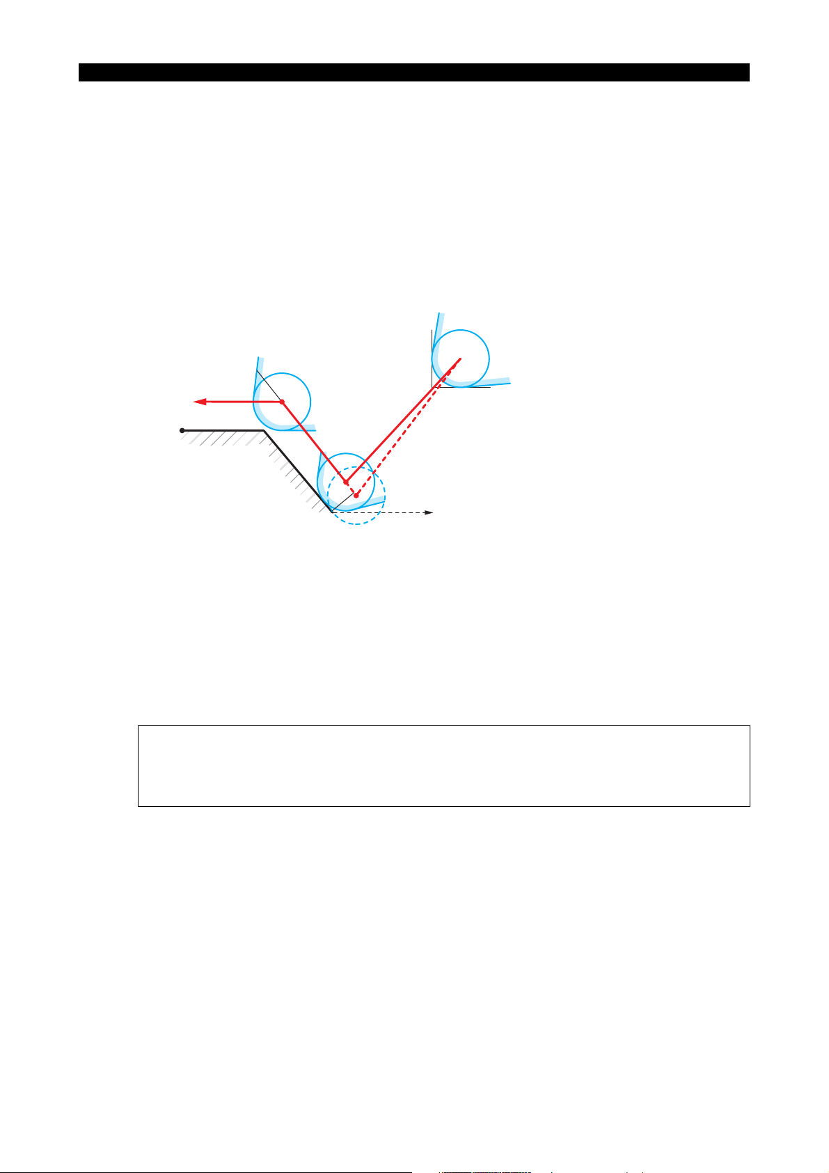
5238-E P-66
SECTION 6 OFFSET FUNCTION
• I and K command with G41 and G42
In the block containing G41 and G42, by entering I and K words that specify the imaginary
point, along with X and Z words that specify the nose radius compensation start-up,
unnecessary axis motion required in conventional start-up program is eliminated.
N1
G00
X100
Z100
F0.2
S1000 T010101 M3
N2
G42
X60
Z80
K20
N3
G01
X80
Z65
N4
Z50
N1
N4
N3
Imaginary point for positioning
N2′ (I,K)
N2
LE33013R0300800090008
If block N2 containing G42 had no I and K words, positioning of the cutting tool by the
commands in block N2 would be executed so that the tool nose radius comes into contact with
line N2-N3 at designated point N2 and then moves to N3.
Addition of I and K words in block N2 positions the cutting tool to the point where the tool nose
R is brought into contact with straight line N2-N3 and imaginary straight line N2-N2’ when the
commands in block N2 are executed. Execution of the commands in block N3 brings the
cutting tool to the programmed point N3 where the tool nose radius compensation is not active.
[Supplement]
• I and K words should be commanded in incremental values. In this case the dimensions are
referenced to point N2.
• When only either I or K is provided without the other, the control interprets the word to have the
value "0". Therefore, KO in the above program can be omitted.
Page 80

1-8-3. Behavior in Tool Nose Radius Compensation Mode
The tool nose radius compensation function provides the means to automatically compensate for
the tool nose radius in continuous cutting.
Since such compensation is performed automatically, there are some restrictions in programming
when the tool nose radius compensation function is used.
Straight line to straight line cutting
Midpoint on a straight line
•
When specifying a midpoint on a straight line, the point should be commanded carefully.
When point N2 in the figure below is located on line N1 - N3, the cutting tool is positioned so
that the tool tip circle comes into contact with line N1 - N3 at point N2.
• Returning along a straight line
Such axis movement causes no problem when the program is written without using the tool
nose radius compensation function.
However, when this function is used the axis movements must be programmed carefully.
Program Example:
5238-E P-67
SECTION 6 OFFSET FUNCTION
N1
N2
N3
X+
X+
G42
G41
N3
N2
Z+
N1
Z+
N2 N3 N1
G01 X1
X2
X3
Z1
Z2
Z3
Cutting tool stops at this point in single
block mode of operation
LE33013R0300800100001
In this example points N2 and N3 are commanded while the cutting tool is at point N1.
When the cutting tool advances from point N1 to point N2, G42 is designated since the cutting
tool moves on the right side of the workpiece with respect to the direction of tool advance.
However, in the return motion of the tool from point N2 to point N3, the cutting tool is on the left
side of the workpiece with respect to the direction of tool advance. Therefore, G41 is specified
instead of G42.
Page 81
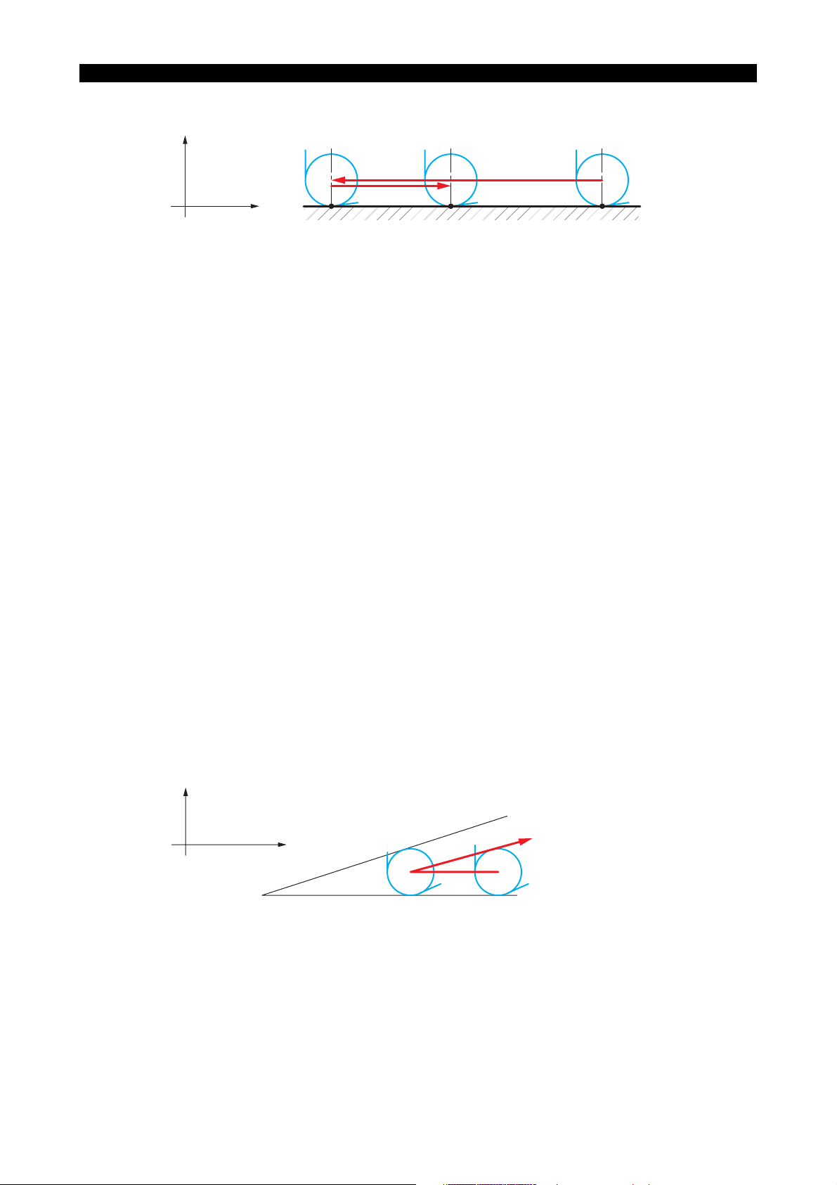
X+
5238-E P-68
SECTION 6 OFFSET FUNCTION
N2′ N3′
Z+
N2 N3
N1′
N1
LE33013R0300800100002
The axis movements above are possible by the special processing for the tool nose radius
compensation function. Let’s consider the operation in this program in the light of section 1-7.
"Path of Tool Nose "R" Center in Tool Nose Radius Compensation Mode."
a. The center of the tool nose R (N2’) at point N2 is obtained as follows:
• The line parallel to the straight line N1 - N2 is obtained, with an upward offset (G42) by
the tool nose radius amount effective at N1.
• The line parallel to the straight line N2 - N3 is obtained, with an upward offset (G41) by
the tool nose radius amount effective at N2.
• The center of the tool nose R is obtained as the point of intersection of the two straight
lines obtained in steps in 1) and 2). However, since those two lines are parallel to each
other, no point of intersection is obtained in this case. For such case, the control has a
special processing feature in which the positioning is carried out so that the tool nose
R comes into contact with point N2. Therefore, the path of the tool nose R center,
when the cutting tool advances from point N1 to point N2, is obtained as N1’ - N2’.
b. The center of the tool nose R (N3’) at point N3 is obtained in the same manner as in 1).
In this way, the program on the previous page can return the cutting tool along the same
straight line with the tool nose radius compensation function active.
If any of these three points is not precisely located on the same straight line, the tool path
will be shifted considerably from the expected path.
• Two lines making an acute angle
In the figure below, although positioning from N1 to N2 is intended, the cutting tool cannot reach
point N2. This is because it can move only up to the point where the tool nose R comes into
contact with line N2 - N3.
X+
N3
Z+
N2 N1
LE33013R0300800100003
This example illustrates a case where programmers are apt to be confused. Another example
is provided below.
Page 82

Example of faulty program 1 (completion of cutting):
N1
N2
N3
X+
G42 G01
G00
X100 Z100 F0.2
Z50
Z300 M05X300
Z+
S1000 T010101 M3
Portion left uncut
N2 N1
5238-E P-69
SECTION 6 OFFSET FUNCTION
N3
LE33013R0300800100004
With the program above, the programmer expected to cut up to point N2, (i.e., up to Z50)
allowing a slight uncut portion on the sharp corner due to tool nose R. Contrary to this intention,
however, the cutting tool leaves a considerable uncut section since it stops before reaching the
desired point.
To improve such a program, enter one more point in the program as shown below:
Example of improved program 1:
N1
G42 G01 X100 Z100 F0.2
N2
N21
Z50
....................................
X104
N3 G00 X300 Z300 M05
X+
S1000 T010101 M3
[ > 100 + 4 x (nose R) ]
N3
N 2 1
Z+
N2 N1
Uncut (due to tool nose radius)
LE33013R0300800100005
The improved program generates the tool path shown above, and almost all the cutting can be
accomplished as expected except for a slight uncut section due to the tool nose R.
To relieve the tool along X-axis in the positive direction in the N21 block, an X word must have a
value larger than four times the nose R. This is because a distance twice the nose R is
Page 83

5238-E P-70
SECTION 6 OFFSET FUNCTION
necessary for the tool tip circle to fit in. In addition, because X words are expressed as
diameters, the X word data has to be doubled. That is, the numerical value in such an X word
must be larger than four times the tool nose R.
If a value smaller than the required amount is used, it might cause the cutting tool to move in
the opposite direction toward point N21 and cut into the N1 - N2 surface.
Example of improved program 2 (using G40):
N1
G42
G01
N2
N3
G40 G00
X100 Z100
X300
Z50
Z300
F0.2
I10
S1000 T010101 M03
M05
X+
Z+
I 10
N 2
N 3
N 1
LE33013R0300800100006
The G40 command in N3 cancels the tool nose radius function. At point N2, the cutting tool
moves so that the tool nose R contacts the line N1 - N2 and the vector I10 extending from point
N2.
• Two lines making an obtuse angle
Consider the case where the cutting tool is fed along the path N0 - N1 - N2 - N3 - N4 in the
figure below.
Angle N2N3N4 is an acute angle and the cutting tool moves along the line outside of that angle.
Therefore, the cutting tool is moved to a point some distance from the workpiece at point N3.
When preparing a program in which cutting similar to this contour is required, it is necessary to
check the safety of tool motion and ensure that the tool does not strike against obstacles when
moving to such a distant point.
N 4
N 2
N 1
N 3
X +
Z +
N 0
LE33013R0300800100007
Page 84

5238-E P-71
SECTION 6 OFFSET FUNCTION
Example program for the path above:
N0 G42 G00 X100 Z300 S1500 T010101 M03
N1
G01 Z100 F0.2
N2
N3
G00
N4 G01
....................................
X104
X200
Z300
Z50 S1000
[ > 100 + 4 × (nose R) ]
LE33013R0300800100008
It is advantageous to improve the program and eliminate a positioning sequence to a distant
point through commands in the N3 block.
If N2N3N4 were not a sharp angle, such a problem would not occur. To eliminate sharp angles
from the required contour, one possible solution is to interpose a short straight line N3 - N31.
X +
N 4
Z +
N 2
N 3
N 31
LE33013R0300800100009
In some cases, such a modification is not possible. In these cases, to cut a sharp angle without
positioning the cutting tool at a distant point, follow the steps detailed below.
Example of Improved Program:
Imaginary shape
N 6
N 7
N 2
N0 G42 G00 X100 Z300 S1500
N1
G01 Z100 F0.2
N2
N3
G00
N4 X198.48
X104
X200.48
Z301
Z301.24 F1
N5 X198 Z300.24
G01
N6 X200 Z300
N7 Z50
F0.2
S1000
N 5
N 3
X+
N 4
Z+
T010101 M03
LE33013R0300800100010
In this improved program, the cutting tool moves along the imaginary square N3N4N5N6. This
permits the operator to estimate the departure of the cutting tool from the programmed contour.
Note that one side of the imaginary square must be longer than twice the nose radius.
Page 85

• Two lines forming a right angle
X+
N 4
5238-E P-72
SECTION 6 OFFSET FUNCTION
N 3
N1 G42 G01 X100
N2
N3
X150
N4
Z+
Z100 F0.2
Z60
Z20
N 2
S1000 T010101 M03
N 1
LE33013R0300800100011
There are no particular problems in this case.
• Command of identical point
a. If a block without axis movement commands is programmed during the tool nose radius
compensation mode, the path of the tool nose R is the same as the one generated when
there is no such block.
N1 G42 G01 X50
N2
N3
N4
X60 Z70
Z100 F0.2
Z80
S1000 T010101 M03
M08
X+
N 4
Z+
N 1
N 3, N2
LE33013R0300800100012
b. When two or more blocks without axis movement commands are programmed, or when the
same point as commanded in the preceding sequence is repeatedly commanded during
the tool nose radius compensation mode:
In this case, an axis motion that brings the tool nose R into contact with the programmed
contour at the programmed coordinate point takes place. When the block of commands
containing dimension words, X and/or Z, is read, the cutting tool returns to the correct
compensated position.
Page 86

SECTION 6 OFFSET FUNCTION
Program 1:
S1000 T010101 M04
Z80
Z80
F0.2
M08
N1 G42 G01 X50 Z100
N2
N3
N4
X60 Z70
A program like this might cause overcutting as shown below:
5238-E P-73
LE33013R0300800100013
X+
N 4
Z+
Overcut portion
N 1
N 3, N2
LE33013R0300800100014
Depending on the contour to be cut, the unexpected motion may not result in overcut, as in
program 2.
Program 2:
N1 G42 G01 X50
N2
N3
N4
X+
X40 Z70
Z100 F0.2
Z80
Z80
S1000 T010101 M04
M08
Z+
N3, N2
N1
N4
LE33013R0300800100015
Page 87

5238-E P-74
SECTION 6 OFFSET FUNCTION
Straight line to arc cutting (arc to straight line cutting)
Arc within one quadrant
•
In a program where the cutting tool moves continuously from a straight line to an arc, the
movement of the cutting tool is handled in the same way as in a case where the movement is
from a straight line to a straight line.
X+
N1 G42
N2
N3
G03
G01
N4
N4
G01 X100
X140
Z+
Z100 F0.2
Z80
Z60
Z40
N3
N2 N1
S1000 T010101 M04
K − 20
LE33013R0300800100016
The tool position at point N2 is determined so that the tool nose R comes into contact with both
line N1 - N2 and arc N2 - N3. At point N3, the cutting tool is positioned in a similar way - the tool
nose R makes contact at point N3.
When the cutting tool moves from point N3 to point N4, the cutting mode changes from circular
interpolation to linear interpolation. If discontinuity at point N3 results during the tool path
calculation, an alarm is displayed and machine operation is stopped.
Page 88

• Arc in two quadrants
a. Case where the arc radius is greater than "2 x nose R":
5238-E P-75
SECTION 6 OFFSET FUNCTION
X+
N4
N3
N1 G42
N2
N3
G02
N4
G01
G01 X100
X140
N2
Z100 F0.2
Z80
Z60
I20
Z40
N1
S1000 T010101 M04
LE33013R0300800100017
The tool position determined by the commands in the N2 block is the point where the tool
nose R comes into contact with line N1 - N2 at point N2. In the N3 sequence, the cutting
tool is positioned so that it comes into contact with both the extension of straight line N2 N3 and the extension of arc N3 - N4.
b. Case where the arc radius is equal to "2 x nose R":
Z+
X+
N1 G42
N2
N3
G02
N4
G01
Z+
G01 X100
X103.2
N4 N3
Z100 F0.2
Z80
Z78.4
I1.6
Z40
N2
Tool nose R = 0.8 mm
S1000 T010101 M04
N1
LE33013R0300800100018
Page 89
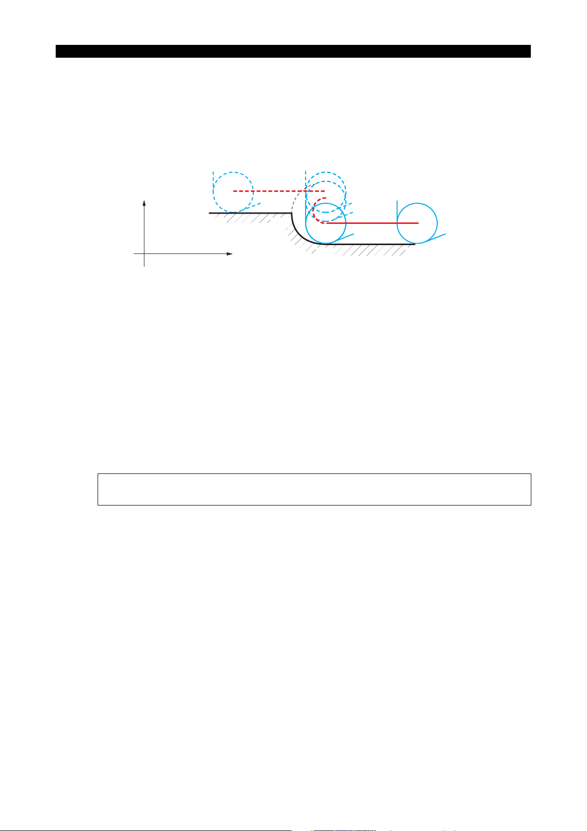
5238-E P-76
SECTION 6 OFFSET FUNCTION
When the radius of the programmed arc equals twice the tool nose R, the cutting tool is
located at the point where the tool nose R comes into contact with both the extension of arc
N2 - N3 and the extension of straight line N3 - N4, after the execution of the commands in
N3 block (see the figure in "1)" above). That is, the cutting tool is positioned right above
point N2, as shown in the figure directly above.
c. Case where the arc radius is less than "2 x nose R" (impossible):
X+
N4 N3
N2 N1
S1000 T010101 M04
N1 G42
N2
G02
N3
G01
N4
G01 X100
X102
Z+
Z100 F0.2
Z80
Z79
Z40
I1
The commands in block N3 specify positioning of the cutting tool at the point where the tool
nose R comes into contact with both the extension of arc N2-N3 and the extension of
straight line N3-N4; however, such a point cannot be obtained. Therefore, when the control
executes the commands in block N3, an alarm occurs and the machine stops.
In this kind of case, cutting using the tool nose radius compensation function is not
possible.
[Supplement]
When cutting inside an arc, the programming must satisfy the following condition:
R 2 x R
(where R: arc radius, RN: nose R)
N
LE33013R0300800100019
Page 90
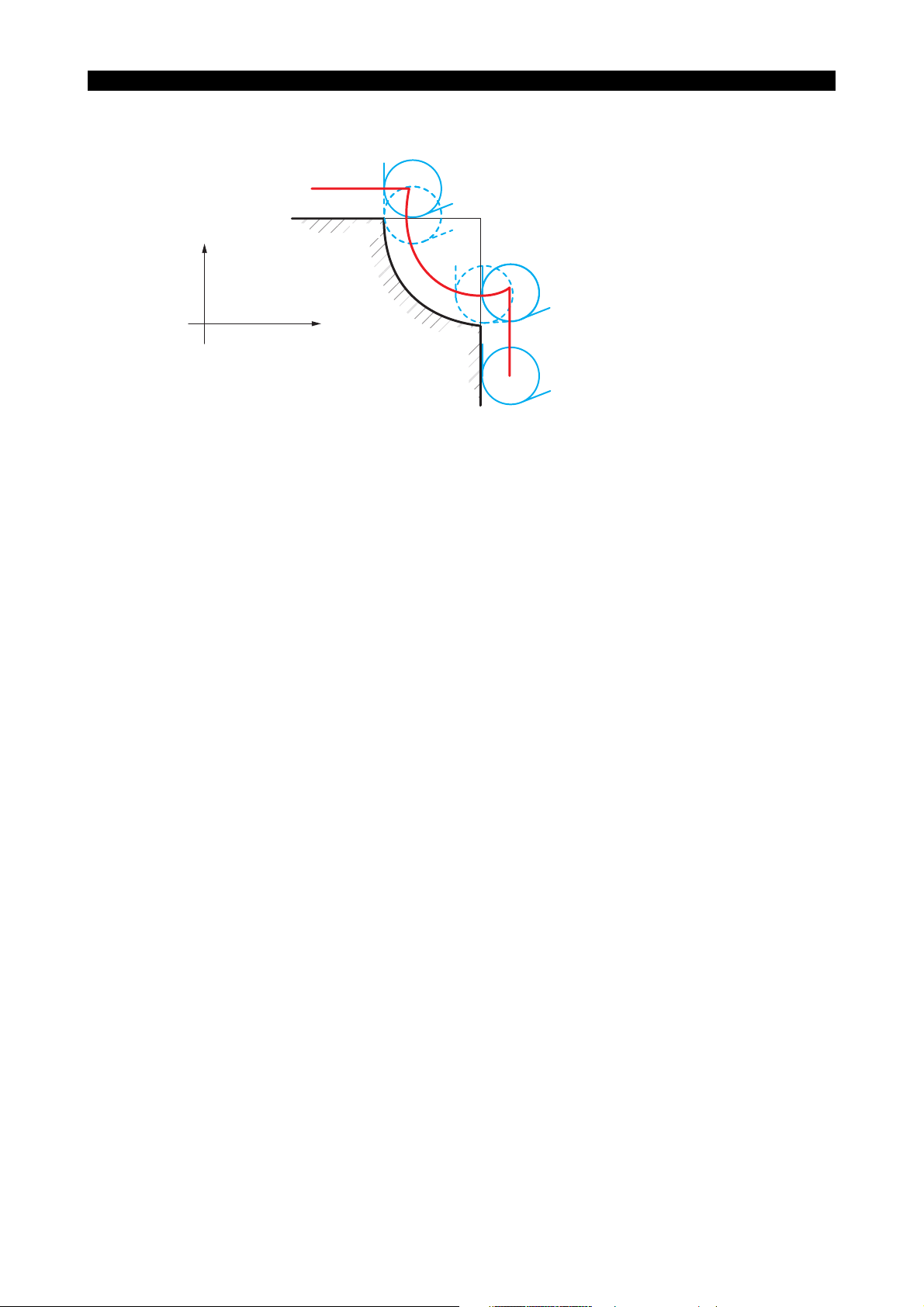
• Arc in three quadrants
5238-E P-77
SECTION 6 OFFSET FUNCTION
X+
N1 G42
N2
N3
G02
N4
G01
N4 N3
Z+
G01 X100
X120
X160 Z80
Z100 F0.2
I20
Z60
N2
N1
S1000 T010101 M04
LE33013R0300800100020
Positioning by the commands in block N2 is to the point where the tool nose R comes into
contact with both the extension of straight line N1 - N2 and the extension of arc N2 - N3.
Other axis motions of the cutting tool are identical to those for cutting an arc in two quadrants.
Page 91
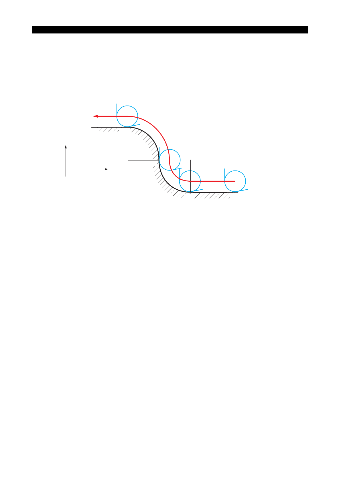
5238-E P-78
SECTION 6 OFFSET FUNCTION
Arc to arc cutting
Arc to arc cutting can be programmed in the same manner as straight line to arc cutting.
The tool path is generated so that the tool nose R is brought into contact with each arc or its
extension.
If the tool path becomes discontinuous in the process of path calculation due to an error, the
machine stops with an alarm displayed on the screen.
Other motions of the cutting tool are as explained in (2), "Straight line to arc cutting".
N4N5
X+
N3
Z+
N1 G42
N2
N3
G02
N4
G03
N5
G01
G01 X100
X140
X180
Z100 F0.2
Z80
I20
Z60
K − 20Z40
Z20
N2
S1000 T010101 M04
N1
LE33013R0300800100021
Page 92

5238-E P-79
SECTION 6 OFFSET FUNCTION
Switching from G41 to G42 or from G42 to G41
Before switching the tool nose radius compensation mode from G41 to G42 or from G42 to G41, it is
advisable to cancel the compensation mode by specifying G40.
If a switch-over is to be done with the compensation mode active, carefully check the movement of
the cutting tool resulting from the switch-over.
• Switch-over in straight line to straight line cutting
Program Example:
N3
Expected tool position
N1
LE33013R0300800100022
X+
N1 G42
N2
N3
G01
G41
G00
G00
N4 X
N4
Z+
A
N2
Z
X
1
X
2
X
3
4
T
1
Z
F
2
Z
3
Z
4
The motion of the cutting tool generated by the above program is as follows:
Commands in blocks, N1 and N2 are governed by G42 and those in blocks N3 and later are
governed by G41. To position the cutting tool at point N2, the tool nose R center lies to the right
side of straight line N1 - N2 since block N2 is in the G42 mode. As for block N3, the tool nose R
center lies to the left side of straight line N2 - N3 since block N3 is in the G41 mode. As a result,
the cutting tool is positioned at point A as shown above.
Positioning in block N2 is carried out at the left side of straight line N2 - N3.
• Switch-over in straight line to arc cutting
The concept is the same as for straight line to straight line cutting.
F
I
3
G41
T
1
K
3
G42
N2
N1 G42
N2
N3
G41
X+
G01
G03
Z+
X
Z
1
1
Z
X
X
2
2
Z
3
3
N3
N1
LE33013R0300800100023
Page 93

SECTION 6 OFFSET FUNCTION
• Switch-over in arc to straight line cutting
Again, the concept is the same as for straight line to straight line cutting.
F
N1 G42
G03
N2
G41
N3
X+
G01
G01
X
Z
1
1
Z
X
X
2
2
Z
3
3
N3 N2
T
1
K
I
2
2
5238-E P-80
Z+
N1
• Switch-over in arc to arc cutting
Once again, the concept is the same as for straight line to straight line cutting.
N1 G42
G02
N2
G41
N3
X+
G01 X
Z
1
1
Z
X
X
N3
2
2
Z
3
3
Z+
F
1
I
2
I
3
N2
T
Z
2
Z
3
N1
LE33013R0300800100024
LE33013R0300800100025
Page 94
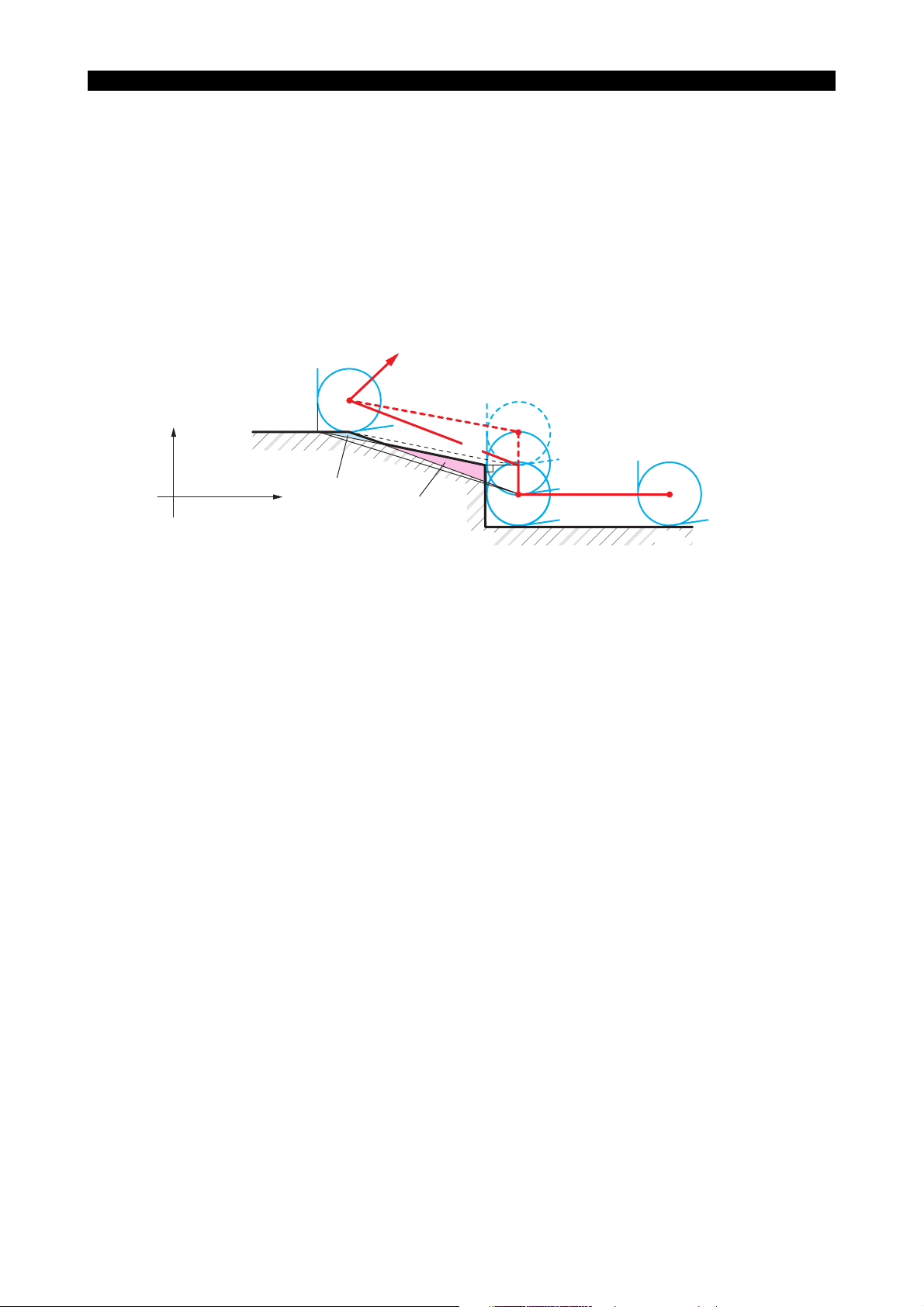
5238-E P-81
SECTION 6 OFFSET FUNCTION
1-8-4. Behavior on Cancelation of the Tool Nose Radius Compensation Mode
G40 given with X- or Z-axis motion command
To cancel the tool nose radius compensation mode, the G40 code is used. It is essential to
understand the cutting tool movements that result from the cancelation of the compensation mode in
order to avoid unexpected trouble.
In the tool nose radius compensation mode, the tool path is generated so that the tool nose R is
always in contact with the programmed contour, but the axis position is controlled so that the tool tip
reference point traces the programmed contour when the tool nose radius compensation mode is
not active. Therefore, under- or over-cut often results when entering into or when canceling the tool
nose radius compensation mode.
O4
X+
N4
Position left uncut
Z+
Overcut portion
N3
O3
O2
O1
N2 N1
LE33013R0300800110001
Cutting a contour comprising straight line segments as illustrated above is programmed as shown
below if the tool nose radius compensation mode is not active.
N1 G01
N2
N3
N4
N5 X300 Z300G00
X100
X120
X130 Z20
F0.2
Z100 S1000 T010101 M03
Z60
LE33013R0300800110002
With the commands above, the cutting tool moves along the path indicated by broken lines. That is,
for designated point N3 the tool center is positioned at point O3, and at point O4 for designated
point N4.
The uncut part parallel to straight line N3 - N4 is left. Therefore the tool nose radius compensation
function can be effectively used to cut such a contour accurately. See the programs on the following
pages.
• When the tool nose R compensation cancel command is designated:
N1 G42 G01
N2
N3
N4
G40
N5 X300 Z300G00
X100
X120
X130 Z20
F0.2
Z100 S1000 T010101 M03
Z60
LE33013R0300800110003
Page 95

5238-E P-82
SECTION 6 OFFSET FUNCTION
The tool path generated in the above program is shown by solid lines.
Positioning fort programmed point N3 is carried out at the point where the tool nose R comes
into contact with point N3, and that for programmed point N4 is carried out at point O4; the
same point reached by the program in which the tool nose radius compensation function is not
activated.
Therefore, the uncut part will be near point N4 while the section near point N3 is overcut.
Improved program:
N5
X+
N4
Z+
N1 G42 G01
N2
N3
N4
N5 X300
G40 G00
X100
X120
X130 Z20
F0.2
Z100 S1000 T010101 M03
Z60
Z300
N3
N2 N1
LE33013R0300800110004
To cut the exact contour up to Point N4, the G40 command which cancels the tool nose radius
compensation mode is specified in block N5.
Although the program yields almost the expected contour, the tool nose R goes beyond the
designated point N4 along Z-axis since it comes into contact with line N3 - N4 at point N4.
When this kind of overtravel causes no interference or overcutting, there are no problems.
Page 96

SECTION 6 OFFSET FUNCTION
• Eliminating possible overcutting along Z-axis, see the program below:
5238-E P-83
F0.2
I10
N5
N3
N2
N1
LE33013R0300800110005
X+
N1 G42 G01
N2
N3
N4
N5 X300 Z300G40 G00
Z+
X100
X120
X130
N5
N4
Portion left uncut
due to round tip
Z100 S1000 T010101 M03
Z60
Z20
I and K words specified in the G40 block allow the tool to move to the point where the tool nose
R is brought into contact with both line N3 - N4 and line N4 - N5.
I and K command with G40
In the block containing G40, by entering I and K words that specify the imaginary point along with X
and Z words that specify the point where nose radius compensation is canceled, unnecessary axis
motion required in conventional canceling program is eliminated.
N1 G42 G01
N2
N3
N4
N5 X300 Z300 I10 K0G40 G00
X+
X100
X120
X130 Z20
Imaginary point for
positioning N5' (I, K)
Z+
F0.2
Z100 S1000 T010101 M03
Z60
N5
O4
O4
N4
Portion left uncut
due to round tip
N3
O3
O2
N2
O1
N1
LE33013R0300800110006
Page 97

5238-E P-84
SECTION 6 OFFSET FUNCTION
If block N5 containing G40 has no I and K words, positioning of the cutting tool by the commands in
block N4 is executed so that the tool nose R comes into contact with line N3 - N4 at designated point
N4 and then moves along the path indicated by broken lines toward point N5.
Addition of I and K words in block N5 positions the cutting tool to the point where the tool nose R is
brought into contact with straight line N3 - N4 and imaginary straight line N4 - N5’ when the
commands in block N4 are executed. Execution of the commands in block N5 brings the cutting tool
to the programmed point N5 where tool nose radius compensation is not active.
[Supplement]
• I and K words should be commanded as incremental values. In this case the dimensions are
referenced to point N4.
• When either I or K only is specified without the other, the control interprets the word to have the
value "0". Therefore, K0 in the above program can be omitted.
Independent G40
When the G40 code is programmed without other commands in the same block, positioning is
carried out at the point where the tool nose R comes into contact with the point specified in the
previous block since the G40 block has no X and Z words which call for axis movement.
N1 G42 G01
N2
N3
N4
N5 G40
N6 X300 Z300G00
X+
X100
Z60
X120
X130 Z20
N4, N5
Z+
F0.2
Z100 S1000 T010101 M03
N6
N3
N2
N1
LE33013R0300800110007
When the tool nose radius compensation mode is canceled (G40), the mode of operation must be
either G00 or G01. If not, an alarm occurs.
1-8-5. Relieving Tool to Change "S" or "M" Code during Cutting
The tool nose radius compensation function is designed to automatically compensate the tool nose
radius in a continuous cutting program; with the dimensions of the workpiece programmed,
compensation is automatically applied to finish the part to the programmed dimensions. However,
such a powerful function requires careful programming when continuous cutting is interrupted to
change S and/or M commands.
This section deals with some programming examples in which the programmer experienced
unexpected results by relieving the cutting tool during cutting on a continuous path.
Page 98

Original contour and associated program (program 1):
5238-E P-85
SECTION 6 OFFSET FUNCTION
X+
N4
N4
Z+
N3
N2
N1
LE33013R0300800120001
Program 1:
N1 G42 G01 X100
N2
N3
X120
N4
F0.2
Z100 S1500
Z80
Z40
S1000
Z20
T010101 M03
LE33013R0300800120002
The original contour comprises: straight line - slope - straight line.
Program 2
The contour is the same as in program 1, but the cutting tool is relieved at point N3 in the +X
direction to change the spindle speed, then continuous cutting is intended.
S" code change
N31
X+
N4
N4
N3
Z+
N32
Uncut portion is left
N2
N1
LE33013R0300800120003
Program 2:
N1
G42
N2
N3
N31
N32
N4
G00
G01
G01 X100
X120
X124
X120
Z100
Z80
Z40
Z20
F0.2 S1500
S1000
T010101 M03
LE33013R0300800120004
In program 2, the cutting tool is positioned at a point where the tool nose R is in contact with line N3
- N31 at point N31 when the commands in block N31 are executed since the three designated points
Page 99

5238-E P-86
SECTION 6 OFFSET FUNCTION
N3, N31 and N32 lie on the same straight line. From N3 to N31, the positioning is on the right hand
side of the line. Commands in block N32 position the cutting tool at the point where the tool nose R
is brought into contact with straight lines N31 - N32 and N3 - N4 on the right side of the direction of
tool advance. This causes the cutting tool to move not only in the X-axis direction but also in the Zaxis direction although block N32 contains only an X word.
Such cutting tool movements leave an uncut portion as shown above.
Program 3
In this program, an attempt is made to eliminate the uncut portion caused by program 2.
Imaginary shape
N32
N2
N1
LE33013R0300800120005
X+
N31
N4
N3
Z+
Overcut portion
Program 3:
N1
G42
G01
N2
N3
N31
N32
N4
G00
X100
X120
X124
X120
G01
Z100
Z80
Z40
Z42
Z20
F0.2 S1500
S1000
T010101 M03
LE33013R0300800120006
When the control feeds the cutting tool from point N2 to point N3, it reads the position data of point
N31 as well as those of point N3. This permits the tool nose R to be positioned at the point where it
is in contact with the two straight lines N2 - N3 and N3 - N31.
After that, positioning is carried out at the point where the tool nose R comes into contact with the
two straight lines N3 - N31 and N31 - N32, when positioning is performed with the commands in
block N31. This moves the cutting tool in the -X direction although the commands in that block
specify tool movement in the +X direction. This is due to the positioning in block N3, where the tool
nose R goes beyond side N31 - N32.
Similarly, positioning of the cutting tool in block N32 is carried out at the point where the tool nose R
comes into contact with both straight lines N31 - N32 and N32 - N4. This also causes the cutting
tool to move in the direction opposite to the programmed direction. The result is overcutting.
Page 100
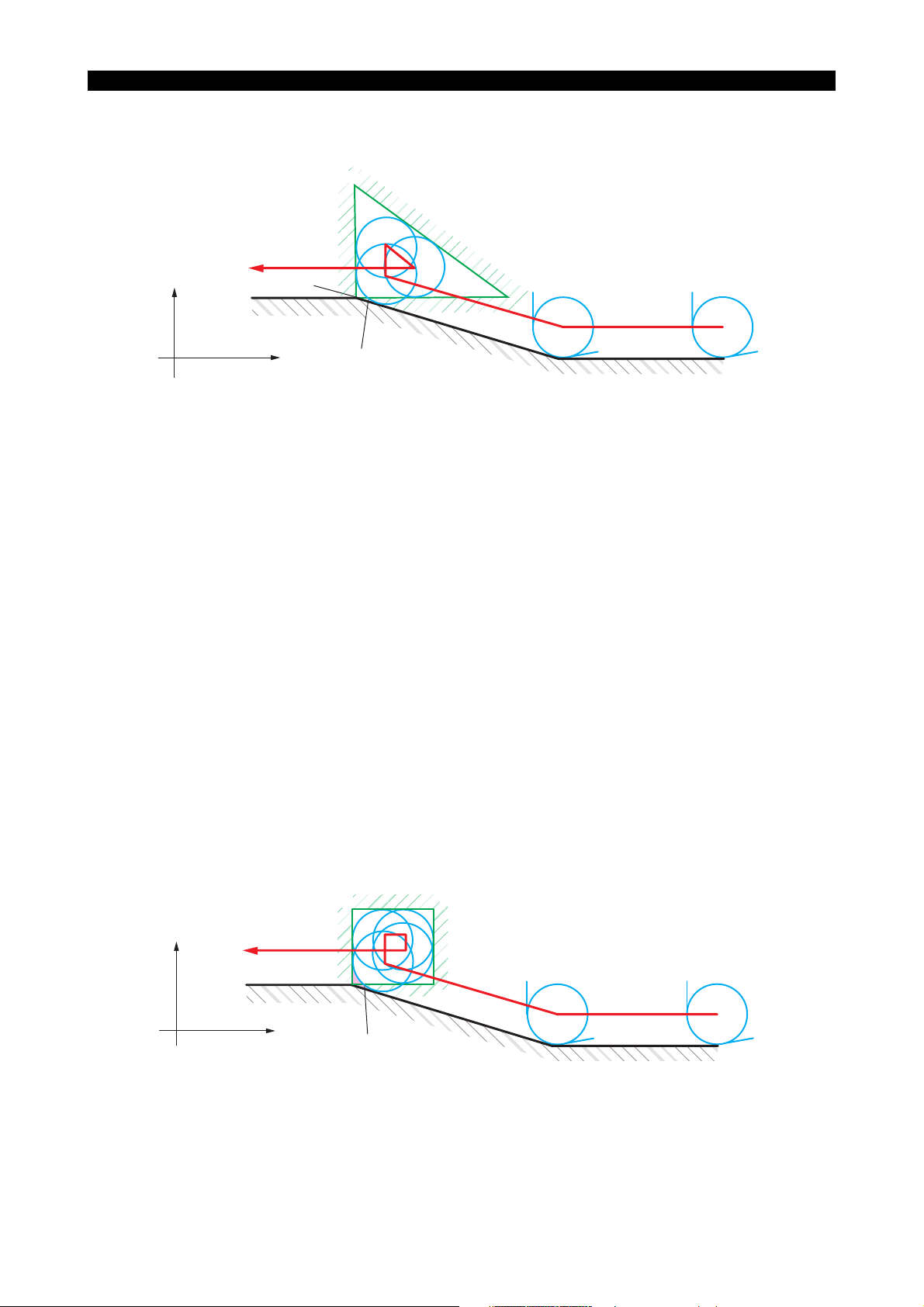
5238-E P-87
SECTION 6 OFFSET FUNCTION
Program 4
N31
Imaginary shape
X+
N4
N3
Z+
Program 4:
In this program, a tool looping similar to that performed in program 3 is executed with the numeral
values modified to avoid overcutting.
N32
N2
N1
LE33013R0300800120007
N1
G42
N2
N3
N31
N32
N4
G00
G01
G01 X100
X120
X126
X120
Z100
Z80
Z40
Z43
Z20
F0.2 S1500
S1000
T010101 M03
LE33013R0300800120008
This program almost yields the expected finish. However, there are still latent problems, such as:
• overcutting is caused depending on the size of the tool nose R
• the length of side N31 - N32 cannot be readily found.
These problems are solved by looping the tool path along a square as explained next.
Program 5
Program 5 solves the problems encountered with program 4.
N31
X+
N32
Imaginary shape
N4
Z+
Portion left uncut
N3
N33
N2
N1
LE33013R0300800120009
 Loading...