

Page 1

CNC SYSTEM
OSP-E100M
OSP-E10M
OPERATION MANUAL
(6th Edition)
Pub No. 4290-E-R4 (ME32-083-R6) Aug. 2002
Page 2

SAFETY PRECAUTIONS
4290-E P-(i)
SAFETY PRECAUTIONS
The machine is equipped with safety devices which serve to protect personnel and the machine
itself from hazards arising from unforeseen accidents. However, operators must not rely exclusively
on these safety devices: they must also become fully familiar with the safety guidelines presented
below to ensure accident-free operation.
This instruction manual and the warning signs attached to the machine cover only those hazards
which Okuma can predict. Be aware that they do not cover all possible hazards.
1. Precautions Relating to Machine Installation
(1) Install the machine at a site where the following conditions (the conditions for achievement of
the guaranteed accuracy) apply.
• Ambient temperature:17 to 25°C
• Ambient humidity:40% to 75% at 20°C (no condensation)
• Site not subject to direct sunlight or excessive vibration; environment as free of dust, acid,
corrosive gases, and salt spray as possible.
(2) Prepare a primary power supply that complies with the following requirements.
• Voltage: 200 V
• Voltage fluctuation: ±10% max.
• Power supply frequency: 50/60 Hz
• Do not draw the primary power supply from a distribution panel that also supplies a major
noise source (for example, an electric welder or electric discharge machine) since this could
cause malfunction of the CNC unit.
Eeoemm1pl001
Eeoemm1pl002
• If possible, connect the machine to a ground not used by any other equipment. If there is no
choice but to use a common ground, the other equipment must not generate a large amount
of noise (such as an electric welder or electric discharge machine).
(3) Installation Environment
Observe the following points when installing the control enclosure.
• Make sure that the CNC unit will not be subject to direct sunlight.
• Make sure that the control enclosure will not be splashed with chips, water, or oil.
• Make sure that the control enclosure and operation panel are not subject to excessive vibra-
tions or shock.
• The permissible ambient temperature range for the control enclosure is 0 to 40°C.
• The permissible ambient humidity range for the control enclosure is 30 to 95% (no conden-
sation).
• The maximum altitude at which the control enclosure can be used is 1000 m (3281ft.).
Page 3

SAFETY PRECAUTIONS
2. Points to Check before Turning on the Power
4290-E P-(ii)
(1) Close all the doors of the control enclosure and operation panel to prevent the entry of water,
chips, and dust.
(2) Make absolutely sure that there is nobody near the moving parts of the machine, and that there
are no obstacles around the machine, before starting machine operation.
(3) When turning on the power, turn on the main power disconnect switch first, then the CONTROL
ON switch on the operation panel.
3. Precautions Relating to Operation
(1) After turning on the power, carry out inspection and adjustment in accordance with the daily
inspection procedure described in this instruction manual.
(2) Use tools whose dimensions and type are appropriate for the work undertaken and the machine
specifications. Do not use badly worn tools since they can cause accidents.
(3) Do not, for any reason, touch the spindle or tool while spindle indexing is in progress since the
spindle could rotate: this is dangerous.
(4) Check that the workpiece and tool are properly secured.
(5) Never touch a workpiece or tool while it is rotating: this is extremely dangerous.
(6) Do not remove chips by hand while machining is in progress since this is dangerous. Always
stop the machine first, then remove the chips with a brush or broom.
(7) Do not operate the machine with any of the safety devices removed. Do not operate the
machine with any of the covers removed unless it is necessary to do so.
Eeoemm1pl003
Eeoemm1pl004
(8) Always stop the machine before mounting or removing a tool.
(9) Do not approach or touch any moving part of the machine while it is operating.
(10) Do not touch any switch or button with wet hands. This is extremely dangerous.
(11) Before using any switch or button on the operation panel, check that it is the one intended.
4. Precautions Relating to the ATC
(1) The tool clamps of the magazine, spindle, etc., are designed for reliability, but it is possible that
a tool could be released and fall in the event of an unforeseen accident, exposing you to danger:
do not touch or approach the ATC mechanism during ATC operation.
(2) Always inspect and change tools in the magazine in the manual magazine interrupt mode.
(3) Remove chips adhering to the magazine at appropriate intervals since they can cause misoper-
ation. Do not use compressed air to remove these chips since it will only push the chips further
in.
(4) If the ATC stops during operation for some reason and it has to be inspected without turning the
power off, do not touch the ATC since it may start moving suddenly.
Eeoemm1pl005
Page 4

5. On Finishing Work
4290-E P-(iii)
SAFETY PRECAUTIONS
(1) On finishing work, clean the vicinity of the machine.
(2) Return the ATC, APC and other equipment to the predetermined retraction position.
(3) Always turn off the power to the machine before leaving it.
(4) To turn off the power, turn off the CONTROL ON switch on the operation panel first, then the
main power disconnect switch.
Eeoemm1pl006
6. Precautions during Maintenance Inspection and When Trouble Occurs
In order to prevent unforeseen accidents, damage to the machine, etc., it is essential to observe the
following points when performing maintenance inspections or during checking when trouble has
occurred.
(1) When trouble occurs, press the emergency stop button on the operation panel to stop the
machine.
(2) Consult the person responsible for maintenance to determine what corrective measures need
to be taken.
(3) If two or more persons must work together, establish signals so that they can communicate to
confirm safety before proceeding to each new step.
(4) Use only the specified replacement parts and fuses.
Eeoemm1pl007
(5) Always turn the power off before starting inspection or changing parts.
(6) When parts are removed during inspection or repair work, always replace them as they were
and secure them properly with their screws, etc.
(7) When carrying out inspections in which measuring instruments are used - for example voltage
checks - make sure the instrument is properly calibrated.
(8) Do not keep combustible materials or metals inside the control enclosure or terminal box.
(9) Check that cables and wires are free of damage: damaged cables and wires will cause current
leakage and electric shocks.
(10) Maintenance inside the Control Enclosure
a) Switch the main power disconnect switch OFF before opening the control enclosure door.
b) Even when the main power disconnect switch is OFF, there may some residual charge in
the MCS drive unit (servo/spindle), and for this reason only service personnel are permitted
to perform any work on this unit. Even then, they must observe the following precautions.
• MCS drive unit (servo/spindle)
The residual voltage discharges two minutes after the main switch is turned OFF.
c) The control enclosure contains the NC unit, and the NC unit has a printed circuit board
whose memory stores the machining programs, parameters, etc. In order to ensure that the
contents of this memory will be retained even when the power is switched off, the memory is
supplied with power by a battery. Depending on how the printed circuit boards are handled,
the contents of the memory may be destroyed and for this reason only service personnel
should handle these boards.
Page 5

(11) Periodic Inspection of the Control Enclosure
a) Cleaning the cooling unit
The cooling unit in the door of the control enclosure serves to prevent excessive temperature rise inside the control enclosure and increase the reliability of the NC unit. Inspect the
following points every three months.
• Is the fan motor inside the cooling unit working?
The motor is normal if there is a strong draft from the unit.
• Is the external air inlet blocked?
If it is blocked, clean it with compressed air.
7. General Precautions
4290-E P-(iv)
SAFETY PRECAUTIONS
(1) Keep the vicinity of the machine clean and tidy.
(2) Wear appropriate clothing while working, and follow the instructions of someone with sufficient
training.
(3) Make sure that your clothes and hair cannot become entangled in the machine. Machine opera-
tors must wear safety equipment such as safety shoes and goggles.
(4) Machine operators must read the instruction manual carefully and make sure of the correct pro-
cedure before operating the machine.
(5) Memorize the position of the emergency stop button so that you can press it immediately at any
time and from any position.
(6) Do not access the inside of the control panel, transformer, motor, etc., since they contain high-
voltage terminals and other components which are extremely dangerous.
(7) If two or more persons must work together, establish signals so that they can communicate to
confirm safety before proceeding to each new step.
8. Symbols Used in This Manual
The following warning indications are used in this manual to draw attention to information of particular importance. Read the instructions marked with these symbols carefully and follow them.
Indicates an imminent hazard which, if not avoided, will result in death or serious
DANGER
injury.
Eeoemm1pl008
Eeoemm1pl009
WARNING
CAUTION
NOTICE
Indicates hazards which, if not avoided, could result in death or serious injury.
Indicates hazards which, if not avoided, could result in minor injuries or damage to
devices or equipment.
Indicates precautions relating to operation or use.
Page 6

INTRODUCTION
4290-E P-(i)
INTRODUCTION
Thank you very much for choosing our CNC system. This numerical control system is a expandable
CNC with various features including a multi-main CPU system. Major features of the CNC system
are described below.
(1) Expandable CNC with a multi-main CPU system
A multi-main CPU system on which up to seven engines (main CPUs) can be mounted is used.
An excellent performance and cost effectiveness have been realized as a leader of increasingly
rapid and accurate machine tools. The CNC system can be adapted to any models and variations by changing the construction of the main CPUs. The machine is controlled by a built-in
PLC.
(2) Compact and highly reliable
The CNC system has become compact and highly reliable because of advanced hardware
technology, including UCMB (Universal Compact Main Board), I/O link, and servo link. The
'variable software' as a technical philosophy of the OSPs supported by a flash memory. Functions may be added to the CNC system as required after delivery.
(3) NC operation panels
The following types of NC operation panels are offered to improve the user-friendliness.
• Color CRT operation panels
• Thin color operation panels (horizontal)
• Thin color operation panels (vertical)
One or more of the above types may not be used for some models.
(4) Machining management functions
These functions contribute to the efficient operation of the CNC system and improve the profitability from small quantity production of multiple items and variable quantity production of variations. Major control functions are described below.
Eeoemm1an001
a) Reduction of setup time
With increase in small-volume production, machining data setting is more frequently
needed. The simplified file operation facilitates such troublesome operation. The documents
necessary for setup, such as work instructions, are displayed on the CNC system to eliminate the necessity of controlling drawings and further reduce the setup time.
b) Production Status Monitor
The progress and operation status can be checked on a real-time basis on the screen of the
CNC system.
c) Reduction of troubleshooting time
Correct information is quickly available for troubleshooting.
(5) Help functions
When an alarm is raised, press the help key to view the content of the alarm.
This helps take quick action against the alarm.
To operate the CNC system to its maximum performance, thoroughly read and understand this
instruction manual before use.
Keep this instruction manual at hand so that it will be available when you need a help.
Screens
Different screens are used for different models. Therefore, the
screens used on your CNC system may differ from those shown
in this manual.
Page 7

CONSTRUCTION OF THIS MANUAL
4290-E P-(i)
CONSTRUCTION OF THIS MANUAL
This instruction manual consists of five chapters.
Eeoemm1i1001
FUNDAMENTALS
This chapter describes the specifications, part names, and functions. Description of the part names
and functions includes explanation of switches on the NC operation panels, screen transition, and
basic operations on each screen.
OPERATION
This chapter describes how to operate the machine from the NC operation panel for different operation modes (manual, MDI, and automatic). The on-screen operating procedures are described in
each operation mode.
DATA OPERATION
This chapter describes file operations, programming operations, parameter and data setting and
other data related operations.
Just like the chapter of Operation, descriptions are given by data setting mode (zero setting, tool
data setting, parameter setting, and programming).
APPENDIX
Appendix includes view of operation panels, tables of EIA/ISO codes, and lists of G codes, M codes,
and system variables.
SPECIAL FUNCTIONS (separate manual)
Some of the functions of the machine and CNC system are described. A description of the concept
necessary for functional operations is added for your further understanding.
Page 8

4290-E P-(i)
TABLE OF CONTENTS
TABLE OF CONTENTS
FUNDAMENTALS
SECTION 1 PART NAMES AND FUNCTION..................................................................1
1. Operation Panels .......................................................................................................................... 1
1-1. Basic Construction of Operation Panels ................................................................................ 1
1-2. Guide to Controls on Operation Panels ................................................................................. 2
2. SCREENS .................................................................................................................................. 12
2-1. Mode Transition Charts ....................................................................................................... 12
2-2. Screen Operations............................................................................................................... 22
3. One-touch Window Close Operation .......................................................................................... 25
OPERATION
SECTION 1 TURNING THE POWER ON AND OFF.....................................................26
1. Turning the Power ON ................................................................................................................ 26
2. Turning the Power OFF .............................................................................................................. 26
3. Emergency Stop ......................................................................................................................... 26
SECTION 2 OPERATION MODES................................................................................27
1. Operation Mode Basic Screen .................................................................................................... 27
1-1. Screen Display .................................................................................................................... 27
1-2. Pop-up Windows ................................................................................................................. 28
SECTION 3 MANUAL OPERATION..............................................................................30
1. Axis Feed Operations ................................................................................................................. 30
1-1. Manual Rapid Traverse Operation ...................................................................................... 30
1-2. Manual Cutting Feed Operation .......................................................................................... 31
1-3. Pulse Handle Feed .............................................................................................................. 32
2. Spindle Operation ....................................................................................................................... 33
2-1. Starting the Spindle ............................................................................................................. 33
2-2. Stopping the Spindle ........................................................................................................... 33
2-3. Releasing the Spindle.......................................................................................................... 33
2-4. Spindle Orientation .............................................................................................................. 33
3. Indexing the Swivel Head and the Attachment ........................................................................... 34
4. ATC............................................................................................................................................. 35
4-1. ATC Operation..................................................................................................................... 35
4-2. Manual Tool Change Operation .......................................................................................... 43
Page 9

4290-E P-(ii)
TABLE OF CONTENTS
4-3. Manual Magazine Operation ............................................................................................... 45
4-4. Manual Tool Change during Automatic Operation .............................................................. 46
5. APC ............................................................................................................................................ 47
5-1. APC Operation .................................................................................................................... 47
5-2. Automatic APC Operations.................................................................................................. 49
5-3. Manual APC Operation........................................................................................................50
6. Others ......................................................................................................................................... 51
SECTION 4 MDI OPERATION ......................................................................................52
1. Procedure for MDI Operation...................................................................................................... 52
2. Automatic Operation and MDI Operation.................................................................................... 53
3. Subprogram Call in MDI Operation............................................................................................. 54
SECTION 5 AUTOMATIC OPERATION........................................................................55
1. Program Files ............................................................................................................................. 55
2. Program Selection ...................................................................................................................... 57
2-1. Selection of Main/Subprogram ............................................................................................ 57
2-2. Schedule Program Function ................................................................................................ 60
3. Cycle Start and Slide Hold .......................................................................................................... 62
3-1. Cycle Start ........................................................................................................................... 62
3-2. Slide Hold ............................................................................................................................ 63
4. Resetting the NC ........................................................................................................................ 65
5. Sequence Number Search and Mid-Cycle Start ......................................................................... 66
5-1. Sequence Number Search .................................................................................................. 66
5-2. Mid-Cycle Start (Start after Sequence Number Search) ..................................................... 69
6. Return Search and Sequence Restart ....................................................................................... 70
6-1. Return Search ..................................................................................................................... 70
6-2. Sequence Restart ................................................................................................................ 73
7. Sequence Stop (Option) ............................................................................................................. 74
8. Single Block ................................................................................................................................ 76
9. Optional Block Skip..................................................................................................................... 77
10.Program Branch.......................................................................................................................... 77
11.Optional Stop .............................................................................................................................. 77
12.Mirror Image Function................................................................................................................. 78
12-1.Mirror Image (Local Coordinate System)............................................................................ 78
12-2.Mirror Image Function in Work Coordinate System............................................................ 81
13.Override ...................................................................................................................................... 84
13-1.Feedrate Override .............................................................................................................. 84
13-2.Spindle Override ................................................................................................................ 84
14.Manual Intervention and Restart................................................................................................. 85
Page 10

4290-E P-(iii)
TABLE OF CONTENTS
15.Pulse Handle Shift Operation ..................................................................................................... 88
16.Lock Functions............................................................................................................................ 89
16-1.Machine Lock ..................................................................................................................... 89
16-2.Axis Command Cancel ....................................................................................................... 89
16-3.Auxiliary (S.T.M) Function Lock.......................................................................................... 89
17.Dry Run....................................................................................................................................... 90
18.Library Program Registration ...................................................................................................... 91
18-1.Registering a library program ............................................................................................. 92
18-2.Erasing a library program ................................................................................................... 93
18-3.Initializing library program storage buffer area ................................................................... 93
18-4.Specifying the library program storage buffer area size ..................................................... 93
19.Editing Selected Program ........................................................................................................... 94
19-1.Quick Edit Function ............................................................................................................ 94
19-2.Editing the Main Program ...................................................................................................96
20.Operation End Lamp (Option)..................................................................................................... 97
21.Operation End Buzzer (Option) .................................................................................................. 97
22.Alarm Lamp (Option) .................................................................................................................. 97
23.Automatic Power OFF (Option) .................................................................................................. 97
24.Work Counter (Option)................................................................................................................ 98
25.Hour Meter (Option).................................................................................................................... 99
25-1.POWER ON TIME Hour Meter .......................................................................................... 99
25-2.NC RUNNING TIME Hour Meter ....................................................................................... 99
25-3.CUTTING TIME Hour Meter ............................................................................................... 99
25-4.SPINDLE REVOLUTION TIME Hour Meter ...................................................................... 99
SECTION 6 NC OPERATION PANEL/SCREEN DISPLAY.........................................100
1. Actual Position Display ............................................................................................................. 100
1-1. ACTUAL POSITION display screen 1/4 (normal display screen) ...................................... 100
1-2. ACTUAL POSITION display screen 2/4
(RELATIVE ACTUAL POSITION display screen) ............................................................. 103
1-3. ACTUAL POSITION display screen 3/4 (Detail display screen)........................................ 106
1-4. ACTUAL POSITION display screen 4/4 ............................................................................ 107
2. Main Program Display .............................................................................................................. 108
2-1. Main program display screen with machine conditions ..................................................... 108
2-2. Main program display screen with subprogram ................................................................. 109
2-3. Main program display screen with valid G/M code ............................................................ 110
3. Schedule Program Display ....................................................................................................... 111
3-1. Schedule program display screen with machine conditions .............................................. 111
3-2. Schedule program display screen with main program....................................................... 112
4. MDI Program Display................................................................................................................ 113
Page 11

4290-E P-(iv)
TABLE OF CONTENTS
5. Block Data Display.................................................................................................................... 114
SECTION 7 HELP FUNCTION ....................................................................................116
1. Help Screen .............................................................................................................................. 117
1-1. Operation with the function menu...................................................................................... 118
1-2. Selecting Operation from the CONTENTS Screen............................................................ 118
2. The Head CONTENTS Screen of POCKETMANUAL .............................................................. 119
3. Search ...................................................................................................................................... 120
4. Terminating the HELP Screen .................................................................................................. 121
5. Supplement............................................................................................................................... 121
DATA OPERATION
SECTION 1 DATA SETTING MODES.........................................................................122
1. Guide to Modes ........................................................................................................................ 122
SECTION 2 ZERO SETTING.......................................................................................123
1. Work Coordinate System Zero Point ........................................................................................ 123
2. Zero Offset Setting.................................................................................................................... 123
2-1. Basic Procedure for Setting Zero Offset Data ................................................................... 123
2-2. Other Operations ............................................................................................................... 125
SECTION 3 TOOL DATA SETTING ............................................................................126
1. Tool Data Setting Operation ..................................................................................................... 126
1-1. Basic Tool Data Setting Operation .................................................................................... 126
1-2. Other Operations ............................................................................................................... 129
2. Tool Shape ............................................................................................................................... 130
3. ATC Pot Number/Tool Number Correspondence ..................................................................... 133
3-1. Memory Random ATC ....................................................................................................... 133
3-2. ATC with Fixed Addresses (Including Multi-magazine) ..................................................... 137
3-3. Collective clear (TOOL CANCEL) and collective setting (TOOL SET) .............................. 141
SECTION 4 PARAMETER SETTING ..........................................................................142
1. Types of Parameter .................................................................................................................. 142
2. Basic Parameter Setting Operations ........................................................................................ 143
2-1. Parameter Setting Screens ............................................................................................... 143
2-2. Setting Parameters ............................................................................................................ 144
2-3. Other Operations ............................................................................................................... 146
3. SETTING THE PARAMETERS ................................................................................................ 149
3-1. General Parameters ..........................................................................................................149
Page 12

4290-E P-(v)
TABLE OF CONTENTS
3-2. NC Optional Parameters ................................................................................................... 163
3-3. Machine User Parameter................................................................................................... 194
3-4. Machine System Parameter .............................................................................................. 223
SECTION 5 PARAMETER I/O FUNCTION .................................................................231
1. Parameter Input/Output Operations.......................................................................................... 231
1-1. Input................................................................................................................................... 232
1-2. Output................................................................................................................................ 233
1-3. Verify ................................................................................................................................. 238
1-4. Correspondence between Q Numbers and Parameters ................................................... 241
1-5. Tape Format ...................................................................................................................... 244
1-6. Supplementary Explanation of Parameter Input/Output Function ..................................... 245
SECTION 6 PROGRAM OPERATIONS......................................................................247
1. Basic Screen in the Program Operation Mode ......................................................................... 247
1-1. DIRECTORY Screen ......................................................................................................... 247
1-2. PROGRAM EDITING Screen ............................................................................................ 248
2. Program File Operations........................................................................................................... 252
2-1. Changing the Directory Display ......................................................................................... 252
2-2. Creating a New File ........................................................................................................... 257
2-3. Displaying a Program Source............................................................................................ 258
2-4. Copying a File.................................................................................................................... 259
2-5. Renaming a File ................................................................................................................ 261
2-6. Deleting a File.................................................................................................................... 262
2-7. Protecting a File................................................................................................................. 263
2-8. File Operations .................................................................................................................. 264
3. Program Editing Operations ..................................................................................................... 277
3-1. Copy .................................................................................................................................. 279
3-2. Delete ................................................................................................................................ 280
3-3. Paste ................................................................................................................................. 281
3-4. 1 Line Insert ....................................................................................................................... 281
3-5. 1 Character Delete ............................................................................................................ 282
3-6. Overwr/Insert ..................................................................................................................... 282
3-7. Another File ....................................................................................................................... 283
3-8. Find.................................................................................................................................... 286
3-9. Replace ............................................................................................................................. 288
3-10.Line Jump ......................................................................................................................... 290
3-11.Sequence No. Arrange ..................................................................................................... 292
3-12.File Insert .......................................................................................................................... 294
3-13.Save ................................................................................................................................. 296
Page 13

4290-E P-(vi)
TABLE OF CONTENTS
3-14.Quit / Stop......................................................................................................................... 297
3-15.Select & Quit..................................................................................................................... 298
3-16.Power Failure Measures in Direct Editing Mode .............................................................. 299
4. Device Information Operations .................................................................................................300
5. Initialization ............................................................................................................................... 301
6. RS232C .................................................................................................................................... 303
6-1. Input/Output Operation ......................................................................................................304
6-2. Tape Format ...................................................................................................................... 310
6-3. Specifications for RS232C Interface.................................................................................. 312
6-4. Connection with External Device....................................................................................... 314
7. Preference Setting Operations .................................................................................................322
7-1. Date/Time .......................................................................................................................... 323
7-2. File Pattern ........................................................................................................................ 324
7-3. File Format ........................................................................................................................ 325
7-4. Sort .................................................................................................................................... 326
7-5. % Code Operation ............................................................................................................. 327
7-6. Edit Mode Property ............................................................................................................ 328
7-7. Display Property ................................................................................................................ 329
APPENDIX
SECTION 1 APPENDED FIGURES ............................................................................330
1. Optional Parameter................................................................................................................... 330
Page 14

FUNDAMENTALS
Page 15

SECTION 1 PART NAMES AND FUNCTION
SECTION 1 PART NAMES AND FUNCTION
1. Operation Panels
1-1. Basic Construction of Operation Panels
4290-E P-1
The machine has eight human-machine interfaces with different applications:
(1) NC Operation Panel
Used for operations other than those in the manual mode, such as file operations and data setting.
(2) Machine Operation Panel
Features the switches and keys used mainly for manual operation.
(3) Option Panel
Used with special machine specifications that require additional switches and indicating lamps.
The arrangement of the switches and indicating lamps differs depending on the selected
optional specification.
(4) Manual Tool Change Panel
Used for changing tools manually.
The arrangement of the switches differs depending on the machine model.
(5) Manual Magazine Operation Panel
Used for operating the magazine manually.
The arrangement of the switches differs depending on the machine model.
(6) APC Operation Panel (for Parallel Type 2-Pallet APC)
Used for operating the pallet changer manually.
The arrangement of the switches differs depending on the machine model.
(7) AAC Operation Panel
Used for changing attachments manually.
(8) Manual Attachment Tool Change Panel
Used for changing tools manually for attachment.
Eeoemm1b2001
Page 16

SECTION 1 PART NAMES AND FUNCTION
1-2. Guide to Controls on Operation Panels
1-2-1. Operation Mode Selection Keys
4290-E P-2
(1) AUTO Key
Pressed to select the automatic operation mode, in which a part program stored in the memory disk (MD) is read to the working memory
of the NC and executed.
(2) MDI Key
Pressed to select the MDI operation mode, in which a program is
written one block at a time from the keyboard of the NC operation
panel and executed in the same way as in automatic operation.
(3) MANUAL Key
Pressed to select the manual operation mode, in which the manual
operation switches on the machine operation panel, pulse handle
operation box, etc., are used to operate the machine.
1-2-2. Data Setting Mode Selection Keys
(1) EDIT AUX. Key
Pressed to select the program operation mode, in which program
files and data files can be edited, punched, printed, displayed, and
deleted.
(2) PARAMETER Key
Pressed to select the parameter mode, in which the following
parameters are set: system parameter, user parameter, common
variables, NC optional parameter, machine system parameter and
machine user parameter.
Eeoemm1b2002
Eeoemm1b2003
P
(3) ZERO SET Key
Pressed to select the zero set mode, in which the zero offset data is
set.
(4) TOOL DATA Key
Pressed to select the tool data mode, in which the tool length offset
data, cutter radius compensation data, ATC tool data, and tool management data can be set, changed, or displayed.
(5) MacMan Key
Pressed to select the MacMan mode, in which the machining management function can be used.
MacMan
Page 17

1-2-3. NC Status Indicating Lamps
4290-E P-3
SECTION 1 PART NAMES AND FUNCTION
S.T.M
Eeoemm1b2004
?
(1) RUN Lamp
This lamp is lit while the machine is actually operating in the automatic or MDI mode.
(2) S.T.M Lamp
This lamp is lit while S (spindle), T (tool), or M (miscellaneous) operation is being executed.
(3) SLIDE HOLD Lamp
This lamp goes on when the [SLIDE HOLD] button is pressed.
(4) PROGRAM STOP Lamp
This lamp is lit during a program stop (M00) or optional stop (M01) in the automatic or MDI
mode.
It blinks during dwell (G04).
(5) LIMIT Lamp
This lamp goes on when an axis reaches the variable limit position.
(6) ALARM Lamp
This lamp goes at the occurrence of an alarm.
Note that it does not light when a warning message is displayed due to erroneous operation.
Page 18

SECTION 1 PART NAMES AND FUNCTION
1-2-4. Other Controls on the NC Operation Panel
4290-E P-4
(1) Function Keys: F1 to F8
When the operator selects an operation mode, the functions (operations) available in the
selected mode are displayed on the bottom line of the screen. The function keys (F1 to F8) correspond to the displays for individual functions, and the functions are executed by pressing the
corresponding function key.
Only those functions that are valid in the current step of an operation and the currently selected
mode are displayed.
F1 F2 F3 F4 F5 F6
(2) Help Key
This key is located to the left of function key [F1].
It is used to display descriptions of alarms which occur during
machine operation, and the alarm history.
(3) Extend key
This key is located to the right of function key [F8].
It is functional only when a triangular mark is displayed at the right
end of the function menu. It is used when all of the accessible items
in a function menu cannot be displayed at one time; pressing the
[Extend] key changes the function menu.
(4) WRITE Key
Press this key to select an operation, and to confirm data after inputting it.
F7 F8
Eeoemm1b2005
(5) BS (Backspace) Key
Used when you have made a mistake in inputting data. Pressing this
key deletes the character input last.
(6) CANCEL Key
Used when you have made a mistake in inputting data. Pressing this
key deletes a line of data that has not been confirmed.
(7) Cursor Keys
These keys move the screen cursor in the directions indicated on
the keys.
(8) Page Keys
If the information called out is displayed in more than one page, the
page keys are used to change the display page.
(9) Operator Keys
These keys are used when multiple data have to be input with operators during program editing or when setting data.
BS
+
P
-
P
/
*
Page 19

SECTION 1 PART NAMES AND FUNCTION
(10) Character Keys
Character keys are used to input characters for data input, program
operation, and file editing operations.
To input the character shown at the upper right corner of a key top,
press the key while holding down the [UPPER CASE] key.
While the [CAPS LOCK] key is pressed (indicating lamp at the upper
left corner of the key lit), these input upper case letters of the alphabet (A to Z). When the [CAPS LOCK] key is not pressed, lower case
letters (a to z) are input.
(11) Ten Keys
The ten keys are used to input numbers for data input, program
operations, and file editing operations.
!
A
SHIFT
7
4
1
0
4290-E P-5
to
+
CAPS
LOCK
8
5
2
.
;
Z
!
A
9
6
3
=
Page 20

1-2-5. Controls on the Machine Operation Panel
4290-E P-6
SECTION 1 PART NAMES AND FUNCTION
The flat keys on the machine operation panel have the features indicated below depending on
whether or not they have indicating lamps.
< Flat keys with an indicating lamp >
The indicating lamp in a key indicates if the function of the key is valid or not.
• Indicating lamp lit: Key function is valid.
• Indicating lamp unlit: Key function is invalid.
< Flat keys without an indicating lamp >
The function of the key is in effect only while the key is held down. While the key is not being
pressed, the function is not in effect.
(1) CONTROL ON Switch
It operates only after the main switch of the machine has been
turned on.
The pilot lamp in this switch lights when the control power is turned
on.
If the [EMERGENCY STOP] button is pressed, the pilot lamp in this
switch goes off. To recover from the emergency stop state, press
the [CONTROL ON] switch again.
(2) CONTROL OFF Switch
When shutting off the power, turn off the control power first by pressing the [CONTROL OFF] switch before turning off the main switch of
the machine.
Eeoemm1b2006
(3) RESTART Switch
This switch is used, for example, to restart the operation which has
been interrupted due to the door interlock function. To restart the
suspended operation, press the [RESTART] switch and then the
[CYCLE START] button.
(4) RESET Switch
Used to recover normal operation when the machine is in the
stopped state due, for example, to an alarm.
(5) NC PANEL Switch
When the UNLOCK position is selected, all operations at the NC
and machine operation panels are enabled.
When the EDIT LOCK position is selected, operations in the program operation (EDIT AUX) mode and (PARAMETER) mode are
disabled.
When the LOCK position is selected, all operations at the NC operation panel are disabled.
(6) CYCLE START Button
The [CYCLE START] button is used to start machine operation as
directed by the commands that have been given.
The CYCLE START signal is output when this button is released
after being pressed.
RESTART
RESET
NC PANEL
EDIT
UNLOCK LOCK
LOCK
CYCLE START
Page 21

SECTION 1 PART NAMES AND FUNCTION
(7) SLIDE HOLD Button
Pressing this button stops motion on the X-, Y-, and Z-axis immediately. To resume axis movements, press the [CYCLE START] button.
If none of the X-, Y-, and Z-axes is moving when this button is
pressed, the slide hold state is established when the current
sequence is completed, or when the next axis motion starts.
4290-E P-7
SLIDE HOLD
(8) EMERGENCY STOP Button
This shuts off the power supply to the machine with the NC power
kept active.
To release the emergency stop state, unlock the [EMERGENCY
STOP] button and press the [CONTROL ON] button.
(9) AXIS SELECT Keys
These keys are used to select the axis to be moved manually (rapid
feed, cutting feed).
To move an axis using the pulse handle, select [PULSE HANDLE].
(10) RAPID Keys
These keys are used to move the axis selected by the [AXIS
SELECT] key at a rapid traverse rate in the direction indicated in a
key.
The selected axis moves at a rapid traverse rate only while the
[RAPID] key is held pressed.
[Supplement]
Rapid traverse rate differs depending on the machine model and specifications.
EMG. STOP
RAPID
+
(11) JOG Keys
These keys are used to move the axis selected by the [AXIS
SELECT] key at a cutting feedrate in the direction indicated in a key.
Once a key is pressed, the axis keeps moving even if it is released.
To stop axis feed, press the [STOP] key.
[Supplement]
Cutting feedrate differs depending on the machine model and specifications.
(12) SPINDLE STOP Key
Used to stop the spindle manually.
(13) SPINDLE CW Key
Used to start the spindle in the forward (CW) direction.
(14) SPINDLE CCW Key
Used to start the spindle in the reverse (CCW) direction.
(15) SPINDLE ORIENTATION Key
Used to stop the spindle at the preset angular position.
To execute spindle orientation, press the [SPINDLE ORIENTATION] key while pressing the [INTERLOCK RELEASE] button.
JOG
+
ORIENTATION
SPINDLE
CW CCW
RELEASE
STOP
Page 22

SECTION 1 PART NAMES AND FUNCTION
(16) SPINDLE RELEASE Key
Used to set the spindle free (neutral position).
[Supplement]
Spindle speeds differ depending on the machine model and specifications.
4290-E P-8
(17) RAPID OVERRIDE Dial
Used to set the desired override value to be applied to the rapid
traverse rate.
(18) FEEDRATE Override Dial
Used to set the desired override value to be applied to the feedrate
specified in a program.
(19) SPINDLE OVERRIDE Dial
Used to set the desired override value to be applied to the spindle
speed specified in a program.
(20) JOG SPEED Dial
The [JOG SPEED] dial is used to set jog feedrate (cutting feedrate).
(21) COOLANT Key
Used to turn on coolant supply.
RAPID
OVERRIDE
%
5030
10
5
1
0
70
60
50
40
30
20
10
%
100
90
80
70
50
500
20
8
200
100
4
50
2
0.04
FEEDRATE
%
95
90
80
5
0
SPINDLE
120
110
(inch/min)
(mm/min)
1000
1
70
80
100
105
110
170
180
200
OVERRIDE
130
140
JOG
SPEED
40
2000
10000
90
120
130
150
160
150
200
80
4000
6000
400
100
140
160
180
160
240
(22) A.B NOZ. Key
(23) A.B ADAPT. Key
(24) OIL MIST Key
(25) OIL HOLE Key
COOLANT
NOZB.A
.
ADAPTB
.
.A
MISTOIL
OIL HOLE
Page 23

(26) OIL HOLE HIGH Key
(27) SHOWER Key
(28) LIGHT Key
(29) LUB. Key
(30) CHIP CON. Reverse Key
Used to operate the chip conveyor in the reverse direction.
The chip conveyor operates only while the key is pressed.
(31) CHIP CON. Forward Key
Used to operate the chip conveyor in the forward direction.
4290-E P-9
SECTION 1 PART NAMES AND FUNCTION
OIL HOLE
HIGH
SHOWER
LIGHT
LUB.
CHIP CON
.
(32) DISPLAY OFF Key
While this function is in effect, the indicating lamp at the upper left
corner of the key is lit.
(33) Door Interlock Mode Selector Switch
For details of the door interlock function, refer to the Instruction
Manual for Safety Door Interlock Function separately issued.
CONCHIP
DISPLAY
OFF
PRODUCTION
SETTING
.
TEST
Page 24

1-2-6. Mode Selection Keys
4290-E P-10
SECTION 1 PART NAMES AND FUNCTION
These switches are used to select the operation mode for program operation.
Eeoemm1b2007
(1) SINGLE BLOCK Key
Used to execute a program block by block.
When this key is valid, the indicating lamp at the upper left corner
lights.
The [CYCLE START] button has to be pressed to execute each successive block.
SINGLE
BLOCK
When the [SINGLE BLOCK] key is invalid (indicating lamp at the
upper left corner unlit), program blocks are executed continuously.
(2) BLOCK SKIP Key
Used to ignore the commands between a slash (/) code and “CR”
code.
When this key is valid, the indicating lamp at the upper left corner
lights.
BLOCK
SKIP
When the [BLOCK SKIP] key is invalid (indicating lamp at the upper
left corner unlit), commands entered after a slash code (/) are executed.
[Supplement]
A slash code (/) must be placed at the start of a program block or immediately after the
sequence number (or sequence name) of a block.
(3) PROGRAM BRANCH Key
Used to execute a program branch instruction in a part program.
The indicating lamp at the upper left corner of the key is lit when the
program branch function is valid.
When the [PROGRAM BRANCH] key is invalid (indicating lamp at
the upper left corner of the key unlit), a program branch instruction in
PROGRAM
BRANCH
1
a part program is not executed.
(4) OPTIONAL STOP Key
Used to stop program operations including spindle rotation and coolant supply.
When this key is valid, the indicating lamp at the upper left corner
lights.
Pressing the [CYCLE START] button in this condition recovers the
OPTIONAL
STOP
state before the stop and starts continuous program execution.
When the [OPTIONAL STOP] key is invalid (indicating lamp at the
upper left corner unlit), program execution proceeds even if a block
containing M01 is executed.
PROGRAM
BRANCH
2
(5) CYCLE STOP Key
Used to stop the operation after the completion of a main program
while the operation is controlled by a schedule program.
When this key is valid, the indicating lamp at the upper left corner
lights.
When the [CYCLE STOP] key is invalid (indicating lamp at the upper
left corner unlit), the operation continues even after the completion
of a main program while the operation is controlled by a schedule
program.
CYCLE
STOP
Page 25

4290-E P-11
SECTION 1 PART NAMES AND FUNCTION
(6) AXIS COM. CANCEL Key
Used to cancel the operation of the specified axis. Designation of an
axis made using a parameter.
When the [AXIS COM. CANCEL] key is valid, the indicating lamp at
AXIS
COM.
CANCEL
the upper left corner lights.
(7) S.T.M LOCK Key
Used to lock miscellaneous functions and enable only axis movements.
S
LOCK
(8) DRY RUN Key
Used to execute axis feed commands (commands in G01, G02, G03
mode, etc.) at the feedrate set with the JOG SPEED dial. The feedrate commands specified in a program are disregarded.
When the [DRY RUN] key is valid, the indicating lamp at the upper
left corner lights.
DRY
RUN
When the [DRY RUN] key is invalid (indicating lamp at the upper left
corner unlit), the axes are fed at the feedrates specified in the program.
[Supplement]
To change the dry run function ON/OFF state, press the [DRY RUN] key while holding down
the [INTERLOCK RELEASE] key.
MT
...
(9) MACHINE LOCK Key
Used to execute a program without actual machine operations.
When the [MACHINE LOCK] key is valid, the indicating lamp at the
upper left corner lights.
If a program is executed with the machine lock function ON, the
actual position display is updated according to the commands as the
program is run. The block data display is also updated. Resetting
MACHINE
LOCK
the CNC restores the display prior to the machine lock.
When the [MACHINE LOCK] key is invalid (indicating lamp at the
upper left corner unlit), commands specifying machine operations
are actually executed.
[Supplement]
To change the machine lock function ON/OFF state, press the [MACHINE LOCK] key while
holding down the [INTERLOCK RELEASE] key.
(10) MIRROR IMAGE Keys
Used to reverse the sign of the coordinate value.
When the [MIRROR IMAGE] key is valid, the indicating
lamp at the upper left corner lights.
When the [MIRROR IMAGE] key is invalid (indicating
MIRROR
IMAGE
X
MIRROR
IMAGE
Y
MIRROR
IMAGE
Z
lamp at the upper left corner unlit), the sign of the specified coordinate value is not reversed.
MIRROR
IMAGE
4
[Supplement]
To change the mirror image function ON/OFF state, press the [MIRROR IMAGE] key while
holding down the [INTERLOCK] key.
Page 26

SECTION 1 PART NAMES AND FUNCTION
(11) INTERLOCK RELEASE Key
This key must be held down when the corresponding mode key is
pressed in order to establish or cancel the dry run mode, machine
lock mode or mirror image mode.
The indicating lamp at the upper left corner of the key is lit, and the
key function is valid, only while the key is pressed.
(12) SEQUENCE RESTART Key
Used during program operation to start a part program from part
way through.
When performing manual operation by interrupting an automatic
operation by pressing the [MID AUTO MANUAL] key, the axes can
be returned to the position where automatic operation was interrupted by pressing the [SEQUENCE RESTART] key.
(13) MID AUTO MANUAL Key
Used to interrupt automatic or MDI mode operation to perform manual operation.
(14) PULSE HANDLE SHIFT Key
Used to add axis movements performed by turning the pulse handle
to the operation executed according to the commands in a part program.
4290-E P-12
INTER
LOCK
RELEASE
SEQUENCE
RESTART
MID.
AUTO
MANUAL
PULSE
HANDLE
SHIFT
2. SCREENS
2-1. Mode Transition Charts
Note that the screens displayed depend on the machine specifications.
Eeoemm1b2008
Page 27
SECTION 1 PART NAMES AND FUNCTION
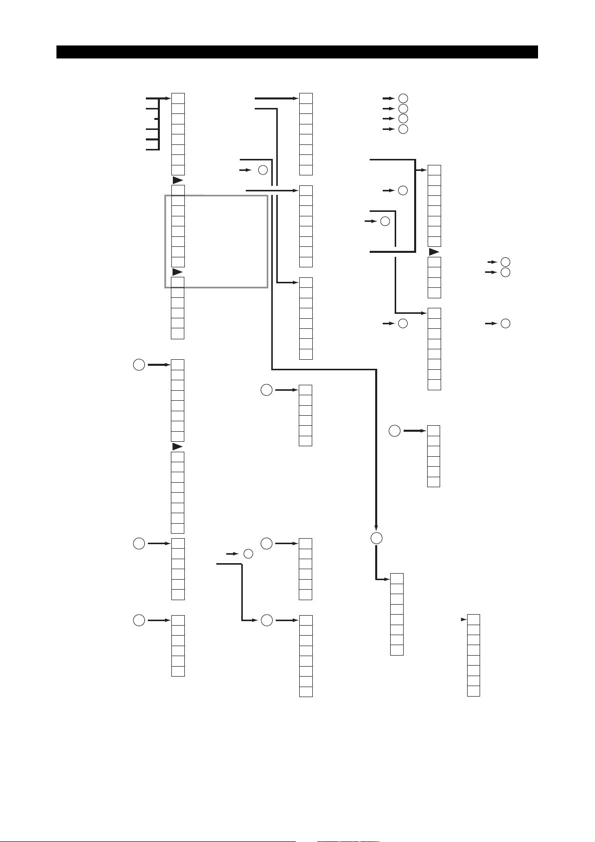
2-1-1. Operation Modes (Automatic / MDI / Manual)
4290-E P-13
ACTUAL POSITION
MAIN PROGRAM
SCHEDULE PROGRAM
MDI PROGRAM
FEED AXIS DATA
BLOCK DATA
1
2
3
F1
MAIN PRG_OPER
F2
ACT_POSI ENLARGE
F3
LOAD ON/OFF
F4
ANIMATE ON/OFF
F5
PROGRAM ON/OFF
F6
QUICK EDIT
F7
NC OPR MONITOR
F8
DISPLAY CHANGE
F1
SCHEDULE PRG_OPR
F2
LIBRARY PROGRAM
F3
F4
PROGRAM MESSAGE
F5
TOOL ON/OFF
F6
TOOL LIST DISPLAY
F7
F8
DISPLAY CHANGE
F1
PARAM.F1 SET
F2
F3
:
F7
F8
F1
F2
F3
F4
F5
F6
F7
F8
F1
F2
F3
F4
F5
F6
F7
F8
F1
F2
F3
:
F7
F8
F1
F2
F3
:
F7
F8
* Refer to next page.
ACTUAL POSITION
MAIN PROGRAM
SCHEDULE PROGRAM
MDI PROGRAM
ANIMATED SIMULATE
CLOSE
MENU CHANGE
DISPLAY PROPERTY
CLOSE
FILE NAME
SORT
OK
CANCEL
OK
CANCEL
F1
PROGRAM SELECT
F2
RESTART
F3
NUMBER STOP
F4
NUMBER SEARCH
F5
EXEC/READ
F6
QUICK EDIT
F7
MAIN PRG_EDIT
F8
1
* Displayed only when [F4] (RELATIVE ACT. POSI) is selected.
4
5
3
6
CLOSE
F1
PROGRAM SELECT
F2
F3
PROGRAM ENTRY
F4
NUMBER SEARCH
F5
SCHEDULE PRG_EDIT
F6
QUICK EDIT
F7
MAIN PRG_EDIT
F8
CLOSE
F1
ACT. POSI (WORK)
F2
ACT. POSI (LOCAL)
F3
MACHINE ACT. POSI
F4
RELATIVE ACT. POSI
F5
POSI SET RELATIVE*
F6
SHIFT ON/OFF
F7
F8
CLOSE
F1
F2
:
F6
ENTRY
F7
ENTRY CANCEL
F8
CLOSE
F1
F2
:
F6
LAST
F7
OK
F8
CLOSE
F1
FILE NAME
F2
SIZE
F3
DATE (UP)
F4
DATE (DOWN)
F5
EXT.
F6
F7
UNSORT
F8
CLOSE
18
3
7
F1
F2
F3
F4
F5
F6
F7
F8
2
Eeoemm1b2020
5
4
3
F1
F2
F3
2
F4
F5
F6
F7
F8
F1
F2
:
F8
F1
F2
7
F3
F4
F5
F6
F7
F8
F1
F2
F3
:
F7
F8
SET
ADD
RELATION PARA.
BACKUP
CLOSE
COPY
DELETE
PASTE
1 LINE INSERT
1-CHAR DELETE
OVER WR/INSERT
PROGRAM SELECT
QUIT
FIND/REPLACE
JUMP
FILE NAME
SORT
ENTRY
ENTRY CANCEL
CLOSE
CLOSE
F1
MENU
F2
F3
:
:
:
F7
BACKUP
F8
CLOSE
EIOEMM1B2025R01
10
11
3
Page 28
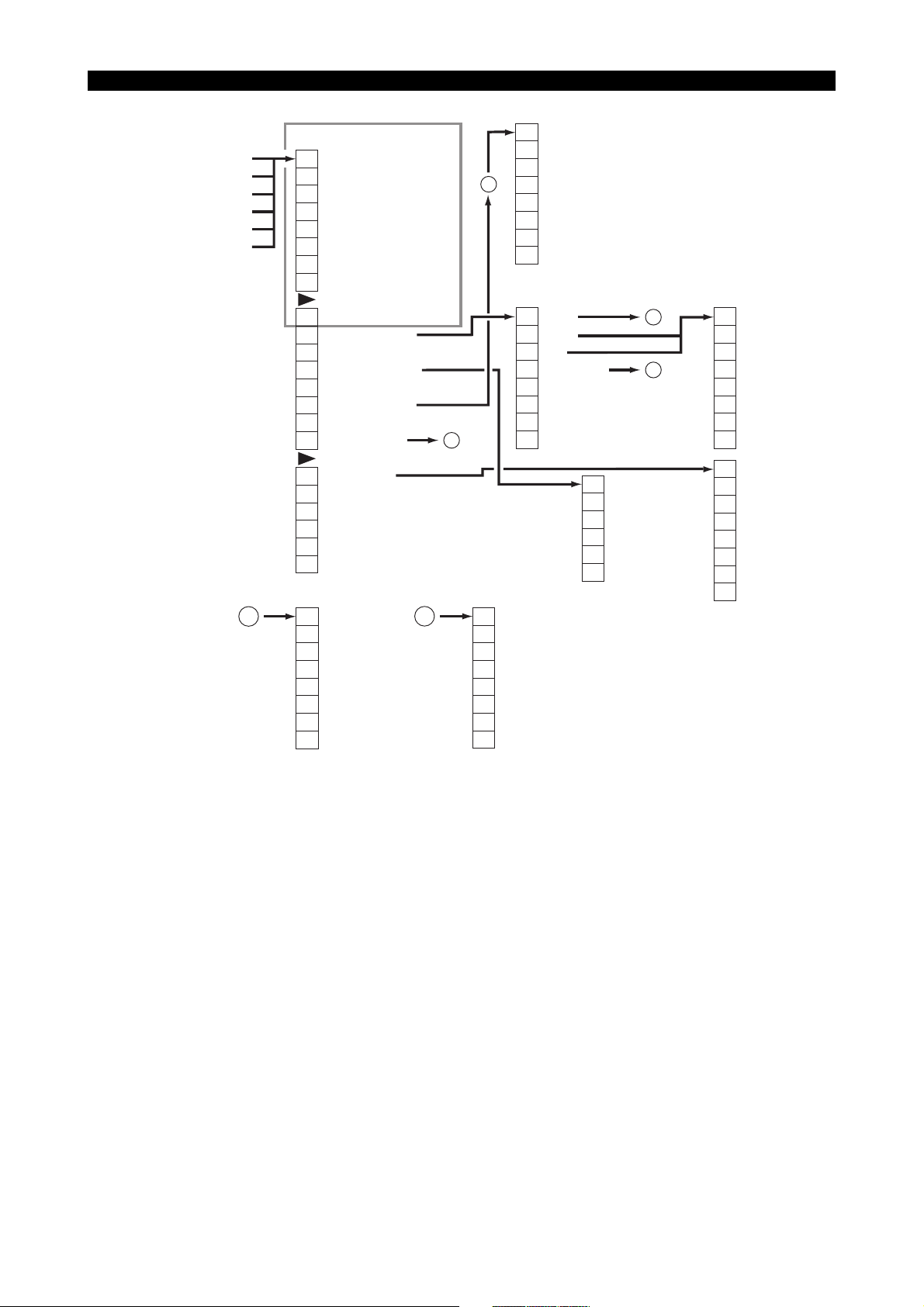
ACTUAL POSITION
MAIN PROGRAM
SCHEDULE
MDI PROGRAM
FEED AXIS DATA
BLOCK DATA
* Refer to previous page.
F1
MAIN PRG_OPER
F2
ACT_POSI ENLARGE
F3
LOAD ON/OFF
F4
ANIMATE ON/OFF
F5
PROGRAM ON/OFF
F6
QUICK EDIT
F7
NC OPR MONITOR
F8
DISPLAY CHANGE
4290-E P-14
SECTION 1 PART NAMES AND FUNCTION
F1
TOOL LIST SELECT
F2
LACK & DISUSED
F3
16
F4
F5
DATA CHANGE
F6
F7
F8
CLOSE
10
F1
SCHEDULE PRG_OPER
F2
LIBRARY PROGRAM
F3
F4
PROGRAM MESSAGE
F5
TOOL ON/OFF
F6
TOOL LIST DISPLAY
F7
F8
DISPLAY CHANGE
F1
PARAM. F1 SET
F2
F3
:
F7
F8
F1
F2
F3
F4
F5
F6
FIND
F7
REPLACE
F8
CLOSE
11
F1
REGIS.
F2
ERASE
F3
INIT
F4
BUFFER SIZE
F5
F6
F7
F8
1
F1
F2
F3
F4
F5
F6
F7
F8
CLOSE
F1
F2
:
F6
F7
F8
TOP PAGE
LAST PAGE
FORWARD
BACK
TOP
CANCEL
2
3
CLOSE
F1
F2
F3
F4
F5
F6
F7
F8
F1
F2
F3
F4
F5
F6
F7
F8
YES
NO
SET
ADD
ACCEL
DECEL
BACKUP
CLOSE
EIOEMM1B2026R01
Page 29
4290-E P-15
SECTION 1 PART NAMES AND FUNCTION
ANIMATED SIMULATION
< > : 3D MODE
F1
MAIN PRG_OPER
F2
TRACE/ANIMATE <TRACE/MATERIAL>
F3
MATERIAL DRAWING
F4
ERASE
F5
PROGRAM ON/OFF
F6
QUICK EDIT
F7
HIGH DRAW
F8
DISPLAY CHANGE
F1
SCHEDULE PRG_OPER
F2
ACT_POSI ENLARGE
F3
LOAD ON/OFF
F4
TOOL ON/OFF
F5
SPLIT/SOLID <SECTION ON/OFF>
F6
<TRNSPRNT ON/OFF>
F7
AUTO SCALE
F8
DISPLAY CHANGE
F1
2D/3D CHANGE
F2
RESTART
F3
GRAPHIC DATA
F4
AREA CHANGE
F5
<ANGLE CHANGE>*
F6
<SECTION CHANGE>
F7
NC OPR MONITOR
F8
DISPLAY CHANGE
Displayed only when a solid
*
drawing is selected with
SPLIT/SOLID in 2D mode.
1
5
8
1
F1
PROGRAM SELECT
F2
RESTART
F3
NUMBER STOP
F4
NUMBER SEARCH
F5
EXEC/READ
F6
QUICK EDIT
F7
MAIN PRG_EDIT
F8
CLOSE
F1
PROGRAM SELECT
F2
F3
PROGRAM ENTRY
F4
NUMBER SEARCH
F5
SCHEDULE PRG EDIT
F6
QUICK EDIT
F7
MAIN PRG_EDIT
F8
CLOSE
F1
ACT. POSI (WORK)
F2
ACT. POSI (LOCAL)
F3
MACHIN ACT. POSI
F4
RELATIVE ACT. POSI
F5
POSI SET RELATIVE*
F6
SHIFT ON/OFF
F7
F8
CLOSE
* Displayed only when [F4] (RELATIVE ACT. POSI)
is selected.
F1
MAGNI.
F2
REDUCE
F3
F4
PLANE/SIDE <NONE>
F5
F6
F7
F8
CLOSE
5
4
3
3
7
2
F1
COPY
F2
DELETE
F3
PASTE
F4
1 LINE INSERT
F5
1-CHAR DELETE
F6
OVER WR/INSERT
F7
PROGRAM SELECT
F8
QUIT
F1
FIND/REPLACE
F2
JUMP
:
F8
F1
F2
FILE NAME
F3
SORT
F4
F5
F6
ENTRY
F7
ENTRY CANCEL
F8
CLOSE
10
11
3
6
F1
DOWN ROTARY
F2
UP ROTARY
F3
RIGHT ROTARY
F4
LEFT ROTARY
F5
F6
F7
F8
CLOSE
F1
Y-Z PL.
F2
Z-X PL.
F3
X-Y PL.
F4
F5
F6
F7
F8
CLOSE
EIOEMM1B2027R01
Page 30
4290-E P-16
SECTION 1 PART NAMES AND FUNCTION
GAUGING RESULTS
F1
MAIN PRG_OPER
F2
ACT_POSI ENLARGE
F3
LOAD ON/OFF
F4
ANIMATE ON/OFF
F5
PROGRAM ON/OFF
F6
QUICK EDIT
F7
F8
DISPLAY CHANGE
F1
SCHEDULE PRG_OPER
F2
TOOL/ZERO
F3
TOOL
ON/OFF
F4
MSB ZERO ON/OFF
F5
MSB TOOL ON/OFF
F6
SENSstat ON/OFF
F7
VARIOUS ON/OFF
F8
DISPLAY CHANGE
F1
PROGRAM SELECT
F2
RESTART
F3
NUMBER STOP
F4
NUMBER SEARCH
F5
EXEC/READ
F6
QUICK EDIT
F7
MAIN PRG_EDIT
F8
1
7
1
CLOSE
F1
PROGRAM SELECT
F2
F3
PROGRAM ENTRY
F4
NUMBER SEARCH
F5
SCHEDULE PRG_OPER
F6
QUICK EDIT
F7
MAIN PRG_EDIT
F8
CLOSE
F1
ACT. POSI (WORK)
F2
ACT. POSI (LOCAL)
F3
MACHINE ACT. POSI
F4
RELATIVE ACT. POSI
F5
POSI SET RELATIVE*
F6
SHIFT ON/OFF
F7
F8
CLOSE
* Displayed only when [F4] (RELATIVE ACT. POSI)
is selected.
2
5
4
3
F1
COPY
F2
DELETE
F3
2
3
7
PASTE
F4
1 LINE INSERT
F5
1-CHAR DELETE
F6
OVER WR/INSERT
F7
PROGRAM SELECT
F8
QUIT
F1
FIND/REPLACE
F2
JUMP
:
F8
F1
F2
FILE NAME
F3
SORT
F4
F5
F6
ENTRY
F7
ENTRY CANCEL
F8
CLOSE
10
11
3
6
NC AXIS DATA
DIAGNOSIS
PLC DATA DISPLAY
F1
STANDARD
F2
MAGNI.
F3
F4
F5
F6
F7
F8
DISPLAY CHANGE
F1
REFER/CHANGE
F2
F3
F4
F5
F6
F7
F8
DISPLAY CHANGE
F1
(BIT ON)
F2
(BIT OFF)
F3
(FORCED ON/OFF)
F4
SEARCH
F5
F6
ID CHANGE
F7
F8
DISPLAY CHANGE
MEMORY DATA
1
M CODE DISPLAY
1
PLC MODULE SKIP
F1
F2
:
F6
F7
OK
F8
1
CANCEL
F1
REFER/CHANGE
F2
ADDRESS UP
F3
ADDRESS DOWN
F4
F5
F6
F7
F8
DISPLAY CHANGE
F1
F2
F3
F4
SEARCH
F5
F6
F7
F8
DISPLAY CHANGE
F1
F2
F3
F4
LABEL/PROGRAM
F5
F6
F7
F8
DISPLAY CHANGE
1
1
1
EIOEMM1B2028R01
Page 31

4290-E P-17
SECTION 1 PART NAMES AND FUNCTION
SPEC CODE
I/O CHECK
PLC DATA DISPLAY
ATC/APC CONDITION
MACHIN DIAGNOSIS
Hi-CUT GUIDE
RS232C CHECK
(CONTROL+D)
CHANGE MODE
(PLC CONTROL MODE)
F1
F2
F3
F4
F5
F6
F7
F8
DISPLAY CHANGE
F1
SEND BUFFER (or RECEIVE BUFFER)
F2
F3
F4
F5
F6
F7
F8
DISPLAY CHANGE
F1
SET
F2
F3
F4
F5
F6
F7
F8
DISPLAY CHANGE
1 1
1
1
PLC DATA TRACE
ATC TOOL SET/DISPLAY
(Memory random)
F1
TRACE START
F2
TRACE QUIT
F3
TRACE SELECT*
F4
DISPLAY POSITION
F5
DATA1/DATA8
F6
CHANGE COND
F7
F8
DISPLAY CHANGE
*Displayed only when
DATA8 is selected with [F5] (DATA/DATA8).
F1
SET (or MENU)
F2
F3
LABEL/IDENT
:
F7
F8
CLOSE
F1
F2
F3
F4
POT SEARCH
F5
TOOL SEARCH
F6
F7
F8
DISPLAY CHANGE
3
1
PLC LADDER MONITOR
F1
MODULE CALL
F2
PAGE SELECT
F3
DISPLAY OPTION
F4
SEARCH
F5
ROLE UP
F6
ROLE DOWN
F7
F8
DISPLAY CHANGE
F1
BIT ON
F2
BIT OFF
F3
F4
F5
F6
F7
F8
SYSTEM VARIABLE
1
F1
AXIS DATA
F2
ZERO OFFSET
F3
TOOL OFFSET
F4
SYSTEM PARA.
F5
HOME POSITION
F6
VNCOM
F7
F8
DISPLAY CHANGE
F1
MSB ZERO OFFSET
F2
MSB TOOL OFFSET
F3
F4
F5
F6
VARIOUS DATA
F7
F8
DISPLAY CHANGE
1
1
EIOEMM1B2006r01
Page 32

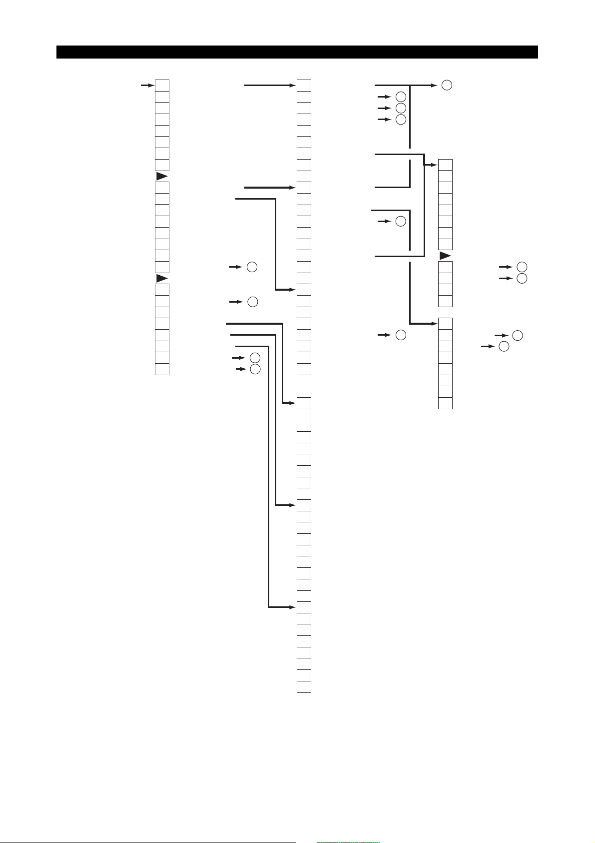
2-1-2. Zero Set Mode
4290-E P-18
SECTION 1 PART NAMES AND FUNCTION
F1
SET
F2
ADD
F3
CAL
F4
FIND
F5
BACK UP
F6
F7
F8
F1
F2
F3
:
F7
DATA IN/OUT
F8
F1
F2
F3
F4
F5
F6
F7
F8
Eeoemm1b2010
OK
CANCEL
12
EIOEMM1B2007R01
Page 33

2-1-3. Tool Data Setting Mode
4290-E P-19
SECTION 1 PART NAMES AND FUNCTION
TOOL OFFSET
/ COMPENSATION
TOOL MANAGEMENT
F1
SET
F2
ADD
F3
CAL
F4
FIND
F5
BACK UP
F6
ITEM ↑
F7
ITEM ↓
F8
DISPLAY CHANGE
:
F6
TOOL LIST
F7
DATA IN/OUT
F8
DISPLAY CHANGE
F1
SET (or MENU)
F2
F3
H/D COMP NO. 2, 3 (or LIFE SETTING)
F4
FIND
F5
BACK UP
F6
ITEM ↑
F7
ITEM ↓
F8
DISPLAY CHANGE
:
F4
SORT
F5
F6
TOOL LIST
F7
DATA IN/OUT
F8
DISPLAY CHANGE
17
16
12
16
12
TOOL SHAPE
DEFINITION
3
9
9
POT NO./TOOL NO.
TABLE (MEMORY-
3
RANDOM)
9
9
F1
SET
F2
F3
F4
F5
BACK UP
F6
ITEM ↑
F7
ITEM ↓
F8
DISPLAY CHANGE
F1
F2
:
F7
DATA IN/OUT
F8
F1
SET
F2
F3
F4
POT SEARCH
F5
TOOL SEARCH
F6
ITEM ↑
F7
ITEM ↓
F8
DISPLAY CHANGE
F1
TOOL CANCEL
F2
TOOL SET
:
F6
F7
F8
DISPLAY CHANGE
Eeoemm1b2021
9
F1
F2
F3
F4
DUMMY TOOL SET
F5
12
TOOL NO. CLEAR
F6
F7
OK
F8
CANCEL
3
3
9
13
9
Window that appears
during command
execution
9
17
F1
F2
F3
F4
F5
F6
F7
F8
CANCEL
F1
F2
:
F8
CLOSE
F1
MENU CHANGE
:
F8
CLOSE
F1
TOOL NO.
F2
GROUP NO.
:
F8
CLOSE
F1
(CHECK MARK)
F2
:
F6
F7
OK
F8
CANCEL
12
13
F1
F2
F3
F4
F5
F6
F7
F8
F1
F2
F3
F4
F5
F6
F7
F8
INPUT
OUTPUT
VERIFY
CLOSE
YES
NO
F1
F2
F3
F4
F5
F6
F7
F8
MENU
NEXT
OK
CANCEL
EIOEMM1B2029R01
Page 34

2-1-4. Parameter Setting Mode
4290-E P-20
SECTION 1 PART NAMES AND FUNCTION
COMMON VARIABLES
USER PARAMETER
G/M CODE MACRO
NC OPTIONAL PARAMETER (INPUT UNIT SYSTEM)
NC OPTIONAL PARAMETER (UNI-DIRECTIONAL POSITION)
NC OPTIONAL PARAMETER (FIXED CYCLE)
NC OPTIONAL PARAMETER (CUTTER R COMPENSATION)
NC OPTIONAL PARAMETER (CIRCULAR INTERPOLATION)
NC OPTIONAL PARAMETER (AUTO SET AT NC RESET/POWER ON)
NC OPTIONAL PARAMETER (
NC OPTIONAL PARAMETER (AXIS COMMAND CANCEL)
NC OPTIONAL PARAMETER (TAPE PUNCH IF)
NC OPTIONAL PARAMETER (BACKUP)
NC OPTIONAL PARAMETER (SYNCHRONIZED TAPPING)
NC OPTIONAL PARAMETER (OPERATING RELATION PARAMETER)
NC OPTIONAL PARAMETER (DISPLAY RELATION PARAMETER)
NC OPTIONAL PARAMETER (MIRROR IMAGE)
NC OPTIONAL PARAMETER (AREA MACHINING)
NC OPTIONAL PARAMETER (LONG, WORD, BIT)
SYSTEM PARAMETER
HOME POSITION
HOME POSITION MOVEMET ORDER
MC AXIS PARAMETER
PITCH ERROR COMPENSATION
ROTARY AXIS PARAMETER
SPINDLE LOAD MONITOR PARAMETER
TAPPING TORQUE MONITOR PARAMETER
DNC-B COMMUNICATION PARAMETER
ONLINE SERVO TUNE-UP (SVTUN)
HI-CUT CONTROL PARAMETER
MC USER PARAMETER (COOLANT)
MC USER PARAMETER (POWER SAVE/SHUTDOWN)
MC USER PARAMETER (TIMER)
MC USER PARAMETER (INDICATING LAMP)
MC USER PARAMETER (BUZZER)
MC USER PARAMETER (SPINDLE)
MC USER PARAMETER (ATC/TOOL EXCHANGE)
MC USER PARAMETER (MAGAZINE)
MC USER PARAMETER (EXTERNAL M COMMAND)
MC USER PARAMETER (EXTERNAL HOUR METER)
MC USER PARAMETER (DOOR INTER LOCK)
MC USER PARAMETER (AXIS LUBE)
MC USER PARAMETER (SYSTEM CHECK MODE)
MC USER PARAMETER (EXTERNAL PROGRAM SELECT)
MC USER PARAMETER (CHUCK, SIT CONFIRMATION, TAILSTOCK)
MC USER PARAMETER (NC AXIS INTERLOCK)
MC USER PARAMETER (APC)
MC USER PARAMETER (ADDITIONAL AXIS)
MC USER PARAMETER (CROSS RAIL)
MC USER PARAMETER (ROBOT/LOADER IF)
MC USER PARAMETER (SPECAIL SPECIFICATIONS)
MC SYSTEM PARAMETER (SPINDLE)
MC SYSTEM PARAMETER (ATC)
MC SYSTEM PARAMETER (APC)
MC SYSTEM PARAMETER (AAC)
MC SYSTEM PARAMETER (HOME POSITION)
MC SYSTEM PARAMETER (MCS)
MC SYSTEM PARAMETER (POWER SEQUENCE)
MC SYSTEM PARAMETER (AXIS EXCHANGE)
MC SYSTEM PARAMETER (ATC ARM PARAMETER)
MC SYSTEM PARAMETER (ATC ARM TORQUE LIMITER)
MC SYSTEM PARAMETER (MC AXIS POSITIONING POINT)
MC SYSTEM PARAMETER (DOOR)
GEOMETRY ENLARGEMENT/REDUCTION
)
F1
∗
F2
∗
F3
∗
F4
∗
F5
∗
F6
ITEM ↑
F7
ITEM ↓
F8
DISPLAY CHANGE
F1
∗
F2
∗
F3
∗
F4
∗
F5
∗
F6
∗
F7
DATA IN/OUT
F8
DISPLAY CHANGE
12
∗
: Depends on the parameter
selected for data setting.
F1
COMMON VAR.
F2
USER PARA
F3
F4
F5
F6
F7
F8
CLOSE
F1
MENU CHANGE
F2
F3
F4
F5
F6
F7
F8
CLOSE
Eeoemm1b2019
F1
(CHECK MARK)
F2
F3
F4
MENU INIT
F5
F6
F7
OK
F8
CANCEL
EIOEMM1B2023R01
Page 35

2-1-5. Program Operation Mode
4290-E P-21
SECTION 1 PART NAMES AND FUNCTION
F1
DIR DISPLAY
F2
EDIT
F3
NEW FILE
F4
LIST
F5
COPY
F6
RENAME
F7
DELETE
F8
PROTECT/UNPROTECT
F1
FILE OPERATE
F2
DEVICE
F3
INIT
F4
RS232C
F5
F6
RUN GUIDE
F7
PREF SETTING
F8
F1
NC PROGRAM
F2
ONETOUCH IGF
:
F8
CLOSE
F1
F2
3
F3
18
F4
F5
F6
F7
F8
22
12
F1
:
F8
3
MD1 COPY
FD0 COPY
ANOTHER COPY
ALL FILE
CANCEL
19
CLOSE
F1
COPY
F2
DELETE
F3
PASTE
F4
1 LINE INSERT
F5
1-CHAR DELETE
F6
OVERWR/INSERT
F7
ANOTHER FILE
F8
QUIT/STOP
F1
FIND/REPLACE
F2
JUMP
F3
SEQ NO. ARRANGE
F4
F5
F6
ADD
F7
SAVE
F8
SELECT & QUIT
F1
COPY
F2
RENAME
F3
DELETE
F4
PROTECT/UNPROT.
F5
VERIFY
F6
F7
F8
CLOSE
Eeoemm1b2022
F1
MD1
F1
DIR DISPLAY
F2
EDIT
F3
NEW FILE
F4
LIST
F5
F6
F7
F8
20
10
11
21
3
CANCEL
F1
DEVICE
F2
FILE NAME
F3
SORT
F4
F5
F6
F7
OK
F8
CANCEL
F1
INDEX SELECT
F2
F3
:
F7
OK
F8
CANCEL
F1
F2
F3
6
F4
F5
F6
F7
F8
F1
F2
F3
:
F7
F8
F1
F2
:
F7
F8
F2
F3
F4
F5
F6
F7
F8
F1
MD1
F2
FD0
F3
F4
F5
F6
F7
OK
F8
CANCEL
FILE NAME
SORT
OK
CANCEL
MENU
NEXT
OK
CANCEL
FD0
MD1 & FD0
ANOTHER DISPLAY
NEW DIR DISPLAY
CLOSE
FILE NAME
SORT
CLOSE
14
6
F1
F2
F3
F4
:
CANCEL
MD1
FD0
OTHERS
1522
14
6
18
F1
DATE/TIME
F2
FILE PATTERN
F3
FILE FORMAT
F4
SORT
F5
% CODE OPERATE
F6
EDIT PROPERTY
F7
DISPLAY PROPERTY
F8
CLOSE
ALL FILE
YES
NO
19
F1
:
F8
CLOSE
F1
:
F7
OK
F8
CANCEL
F1
MENU
F2
NEXT
:
F7
OK
F8
CANCEL
ALL FILE
PROTECT
UNPROTECT
CANCEL
F1
F2
F3
F4
F5
F6
F7
F8
MENU
NEXT
SORT
REDRAW
CLOSE
20
15
14
ONCE STOP
YES
NO
CANCEL
F1
ALL FILE
F2
MAIN PROGRAM
F3
SCHEDULE PROGRAM
F4
SUB PROGRAM
F5
IGF FILE
F6
JOB FILE
F7
MEMO FILE
F8
CLOSE
21
YES
NO
CANCEL
EIOEMM1B2030R01
Page 36

2-2. Screen Operations
4290-E P-22
SECTION 1 PART NAMES AND FUNCTION
There are three methods for moving between screens, as described below.
(1) Menu based screen selection
Screen selection from the menu is used in automatic, MDI, and manual operation modes and
parameter, zero point, and tool data setting modes.
Select the [DISPLAY CHANGE] function menu item on the initial screen of each mode to display the DISPLAY CHANGE pop-up window.
Eeoemm1b2023
Fig.1-1 DISPLAY CHANGE Pop-up Window
EIOEMM1B2031R01
Use the up/down cursor keys to select the screen to be displayed, then select [CLOSE] from the
function menu to switch to that screen.
Pressing the (WRITE) key when the cursor is located on [CLOSE] in the DISPLAY
CHANGE pop-up window has the same effect as selecting [CLOSE] from the function menu.
[Supplement]
In the parameter setting, zero point setting, and tool data setting modes, the current screen
can be reversed to the previous one or advanced to the next one by depression of F6]
(ITEM↑) [or [F7] (ITEM↓). This is just the same as you select the screen before or after the
current screen from the menu.
[F6] (ITEM↑): The screen reverses to the one displayed before the current screen.
[F7] (ITEM↓): The screen advances to the one displayed after the current screen.
Page 37

4290-E P-23
SECTION 1 PART NAMES AND FUNCTION
(2) Transition between functions (short-cut operation)
This method is available only in the operation modes (automatic operation mode, MDI operation
mode, manual operation mode).
Select [DISPLAY CHANGE] from the function menu on the initial screen for any operation mode
to display a pop-up menu with the names of the screens that can be displayed indicated in it.
Fig.1-2 Pop-up Function Menu
Selecting the required screen from this pop-up menu gives short-cut access to it.
(3) Screen transitions with the page keys
The page keys are used when the currently displayed screen has more than one page, and for
switching between enlarged and batch displays on the ACTUAL POSITION display screen.
a) Switching among multiple pages
Whether or not the currently displayed screen has multiple pages can be determined from
the page label at the top right of the screen. If there is only one page there is no page label;
if there are multiple pages the label shows an expression indicating the page number and
total number of pages, for example “1/4.”
If there are multiple pages, the other pages can be viewed by pressing the page keys.
EIOEMM1B2032R01
b) Switching actual position screen between normal display and detail display
The ACTUAL POSITION display screen has four forms: two normal display screens and two
detail display screens. The detail display screen displays more or less all of the required
information on one screen. It is possible to switch the display screens by pressing the page
keys.
The ACTUAL POSITION display screen can enlarge only the X-, Y- and, Z-axis data.
When you select [F2] (ACT POSI ENLARGE) from the function menu on the actual position
display screen, the actual position pop-up window appears.
Select a required coordinate system (or relative actual position) from the pop-up function
menu, and the actual position data in the selected coordinate system appears.
Page 38

2-2-1. Function Menu
4290-E P-24
SECTION 1 PART NAMES AND FUNCTION
(1) Function menu selection
In cases where it is not possible to display all the function menu items corresponding to function
keys F1 through F8 on one screen, a black triangular symbol is displayed at the right end of the
function menu.
When this symbol is displayed, the function menu items not currently displayed can be displayed by pressing the [Extend] key located to the right of the [F8] key.
Fig.1-3 Function Menu Selection
(2) Pop-up Function Menus
If a function displayed in the function menu has a sub menu, selecting that function menu item
causes the sub menu to be displayed superimposed on the existing function menu. This kind of
menu is called a “pop-up function menu”. This menu is closed by selecting [CLOSE] from the
function menu. (With some functions, the menu automatically closes on completion of command execution.)
[Supplement]
If the pop-up window contains a [CLOSE] or [OK] button, pressing the (WRITE) key
while this button is selected has the same effect as selecting [CLOSE] (or [OK]) in the pop-up
function menu.
Eeoemm1b2015
EIOEMM1B2035R01
2-2-2. Pop-up Windows
In addition to the basic screen and menu function displays, the screen displays also include pop-up
windows that are displayed when specific functions are selected.
Some pop-up menus are alternately displayed and not displayed by repeated selection of a function
menu item, while others automatically close on completion of execution of the corresponding command.
Fig.1-4 Pop-up Function Menu
EIOEMM1B2032R01
Eeoemm1b2016
Page 39

SECTION 1 PART NAMES AND FUNCTION
3. One-touch Window Close Operation
4290-E P-25
If the mode selection key that corresponds to the currently selected mode is pressed when the popup window is open, the current processing is aborted and the screen returns to the initial state. This
operation is called one-touch close operation.
The processing for closing the window varies depending on the case where one-touch close operation is used. The following is the processing in each case:
(1) During program editing
a) Normal editing mode
The message “ALL WINDOW CLOSE. DATA SAVE OK?” appears in the message window.
• Select [F6] (YES) to save the file data, close all the pop-up windows, and initialize the
DIRECTORY screen display.
• Select [F7] (NO) to close all the pop-up windows without saving data and initialize the
DIRECTORY screen display. In this case, note that all the data being edited is lost.
• Select [F8] (CANCEL) to abort one-touch window close processing.
b) Direct editing mode (large volume)
The message “ALL WINDOW CLOSE OK?” appears in the message window.
• Select [F6] (YES) to renew the file, close all the pop-up windows, and initialize the
DIRECTORY screen display.
• Select [F7] (NO) to abort one-touch window close processing.
Eeoemm1b2024
Page 40

OPERATION
Page 41

SECTION 1 TURNING THE POWER ON AND OFF
SECTION 1 TURNING THE POWER ON AND OFF
1. Turning the Power ON
4290-E P-26
Turn ON the main switch in the control cabinet.
To turn on the power, press the [CONTROL ON] switch on the machine
operation panel.
An alarm or error is generated, refer to the ALARM & ERROR LIST
separately issued.
2. Turning the Power OFF
Before turning the power off, make sure that the machine has stopped
with all command execution completed.
If there is a peripheral device (printer, punch, etc.) connected to the NC,
switch it off.
Press the [CONTROL OFF] switch on the machine operation panel.
Turn OFF the main switch in the control cabinet.
CAUTION
Data such as tool length offset data, cutter radius compensation data, zero point of work coordinate systems, parameters (excluding system parameters), etc., are backed up in the backup
memory at preset intervals only; this means that if the power is turned OFF immediately after
making a change to the data, the changed data may not be backed up. Before turning off the
power immediately after changing data, back up the data. For details on the back up operation,
see the explanation of back up operation in each of data setting operations.
Eeoemm1o1001
Eeoemm1o1002
3. Emergency Stop
Press the [EMERGENCY STOP] button.
This stops the machine immediately.
To unlock the button, turn it in the direction indicated by the arrows.
After unlocking the [EMERGENCY STOP] button, press the [CONTROL
ON] switch on the machine operation panel to recover from the emergency stop state.
Eeoemm1o1003
EMG. STOP
Page 42

SECTION 2 OPERATION MODES
1. Operation Mode Basic Screen
4290-E P-27
SECTION 2 OPERATION MODES
The following is a general description of the basic screen and pop-up window displayed for operation modes.
1-1. Screen Display
(1) Information at top of screen
Information is provided at two locations at the top of operation mode screens: the status display
and the title bar.
The information usually displayed is shown below (the items in the left-hand column of the table
are examples):
(Symbol at left) Symbol indicating the operation mode
AUTO OPERATION Indicates the current mode.
OSP-E100M.MIN Indicates the selected main program file name.
A-MTD Indicates the selected operation method.
2002/05/23 Indicates the date.
9 : 13 : 05 Indicates the current time.
(Left-hand symbol at bottom right) Displayed when editing is in progress.
(Right-hand symbol at bottom
right)
Eeoemm1o2002
Eeoemm1o2003
Fig.2-1 Status Display
EIOEMM1O2001r01
Displayed when the help window is opened.
Fig.2-2 Screen Title Bar
ACTUAL POSITION This is the title of the screen.
1mm (PROGRAM) Indicates the unit system used to run the program.
0 Indicates the currently selected main program name.
N0100
19 Indicates the block counter.
(2) Function Menu
There is a number of patterns for the function menu which is displayed in the operation modes.
The pattern differs according to the operation mode and the screen displayed.
For details on the function menu items displayed, refer to SECTION 2 PART NAMES AND
FUNCTIONS, 2-1 “Mode Transition Charts” in FUNDAMENTALS.
Indicates the sequence name executed last in the
main program.
EIOEMM1O2002r01
Page 43

1-2. Pop-up Windows
4290-E P-28
SECTION 2 OPERATION MODES
When any of the function menu items is selected, the corresponding pop-up window is displayed.
Apart from pop-up windows in which data can be set, there are also DISPLAY CHANGE pop-up
windows that are used to change the screen contents.
(1) About DISPLAY CHANGE pop-up windows
To change the screen contents in an operation mode, first display the DISPLAY CHANGE popup window, then select the required screen.
The DISPLAY CHANGE pop-up window is displayed by selecting [F8] (DISPLAY CHANGE)
from the function menu on the initial screen of any mode.
Eeoemm1o2004
Fig.2-3 DISPLAY CHANGE Pop-up Window
EIOEMM1O2006R01
The pop-up function menu displayed while the DISPLAY CHANGE pop-up window is on the
screen contains the items MENU CHANGE and DISPLAY PROPERTY in addition to short-cuts
used to select various screens.
In each menu screen, the following settings can be made.
Page 44

SECTION 2 OPERATION MODES
MENU CHANGE
Used to set the menu displayed in the DISPLAY CHANGE pop-up window.
4290-E P-29
Fig.2-4 MENU CHANGE Pop-up Window
EIOEMM1O2007R01
DISPLAY PROPERTY
Used to choose between negative and positive for the ACTUAL POSITION window, for program display, and for the text editor.
Fig.2-5 DISPLAY CHANGE Pop-up Window
EIOEMM1O2008R01
Page 45

SECTION 3 MANUAL OPERATION
4290-E P-30
SECTION 3 MANUAL OPERATION
The following operations are possible when the manual operation mode is selected. In the automatic
operation mode and MDI operation mode, these operations are also possible if the manual intervention mode is selected.
• Axis feed operations (rapid traverse, cutting feed, pulse handle feed)
• Spindle operations (rotation, stop, release, orientation)
1. Axis Feed Operations
1-1. Manual Rapid Traverse Operation
Select the desired axis by the [AXIS SELECT] keys on the machine operation panel, and press
either of the [RAPID] keys. The selected axis moves at a preset rapid traverse rate.
The rapid traverse rate can be changed by setting the RAPID OVERRIDE dial on the machine operation panel.
To feed an axis at a rapid traverse rate follow the procedure indicated below.
Procedure :
1 Select the desired axis by the [AXIS SELECT] keys.
Eeoemm1o3001
Eeoemm1o3002
2 Set the desired override rate (%) by the RAPID OVERRIDE dial.
Setting of the RAPID OVERRIDE dial may be changed even if an
axis is moving.
3 Press either of the [RAPID] keys.
To feed the selected axis in the positive direction, press the [+] key
and press the [–] key to feed the axis in the negative direction. The
selected axis moves at a rapid traverse rate only while a [RAPID]
key is held pressed.
RAPID
OVERRIDE
%
5030
10
5
1
0
70
80
90
100
RAPID
+
Page 46

1-2. Manual Cutting Feed Operation
4290-E P-31
SECTION 3 MANUAL OPERATION
Select the desired axis by the [AXIS SELECT] keys on the machine operation panel, and press
Eeoemm1o3003
either of the [JOG] keys. The selected axis moves at a feedrate set with the [JOG SPEED] switch.
To feed an axis at a cutting feedrate follow the procedure indicated below.
Procedure :
1 Select the desired axis by the [AXIS SELECT] keys.
2 Select the desired feedrate by the [JOG FEED] switch.
Setting of the [JOG SPEED] switch may be changed even if an axis
is moving.
For this operation, the [FEEDRATE] override dial can be used to
change the selected cutting feedrate.
3 Press either of the [JOG] keys.
To feed the selected axis in the positive direction, press the [+] key
(inch/min)
(mm/min)
500
20
8
200
100
4
50
2
0.04
1
1000
40
10000
JOG
SPEED
2000
80
4000
6000
400
160
240
JOG
and press the [–] key to feed the axis in the negative direction.
Once the key is pressed, the key remains valid until the [OFF] key
+
is pressed.
4 Press the [OFF] key to stop the axis.
Page 47

1-3. Pulse Handle Feed
4290-E P-32
SECTION 3 MANUAL OPERATION
On the machine operation panel, select the [PULSE HANDLE] key in the [AXIS SELECT] keys and
select the desired axis by the pulse handle axis selection switch. Turn the pulse handle and the
selected axis moves as the pulse handle is rotated.
The magnification selection switch is provided to select the axis feed distance per pulse.
To feed an axis using the pulse handle, follow the procedure indicated below.
Procedure :
1 Select the [PULSE HANDLE] key in the [AXIS SELECT] keys.
2 Select the axis feed distance per pulse by the magnification selec-
tion switch.
x1 Moves an axis 0.001 mm per pulse.
x10 Moves an axis 0.01 mm per pulse.
x50 Moves an axis 0.05 mm per pulse.
3 Select the desired axis by the pulse handle axis selection
switch.
Eeoemm1o3004
MAGNIFICATION
4 Turn the pulse handle.
Turning the pulse handle clockwise moves the axis in the positive
direction.
Turning the pulse handle counterclockwise moves the axis in the
negative direction.
[Supplement]
If you turn the pulse handle quickly by selecting a large pulse multiplication ratio, the axis may
move at a feedrate close to rapid traverse rate. This could cause an alarm.
OKUMA
Page 48

2. Spindle Operation
4290-E P-33
SECTION 3 MANUAL OPERATION
If the [SPINDLE CW] or [SPINDLE CCW] key on the machine operation panel is pressed in the state
a spindle speed is set using an S command in such as the MDI operation mode, the spindle starts
rotating at the specified speed. Pressing the [SPINDLE STOP] key stops the spindle. The spindle
speed can be changed by using the [SPINDLE OVERRIDE] dial.
2-1. Starting the Spindle
Before attempting to start the spindle, set the spindle speed using an S
command in the MDI operation mode. This selects the gear range automatically. Note that an S command cannot be specified manually.
Next, select the manual operation mode and press either of the [SPINDLE CW] and [SPINDLE CCW] switches while pressing the [INTERLOCK RELEASE] key.
The spindle starts rotating at the speed calculated by multiplying the
specified spindle speed by the set override value.
2-2. Stopping the Spindle
Press the [SPINDLE STOP] key to stop the spindle.
2-3. Releasing the Spindle
Eeoemm1o3006
Eeoemm1o3007
Eeoemm1o3005
ORIENTATION
SPINDLE
CW CCW
%
SPINDLE
110
100
90
80
70
50
STOP
120
RELEASE
OVERRIDE
130
140
150
200
160
180
Press the [SPINDLE RELEASE] key to set the spindle drive gears in the neutral (released) position.
This operation becomes valid only after the spindle has stopped.
Once the spindle is released, the spindle can be rotated manually.
If you start the spindle in the state the spindle is released, the previously selected spindle drive gear
is selected and the spindle rotates at the speed specified by the previous S command.
The spindle released state can be canceled only by spindle start operation.
2-4. Spindle Orientation
Press the [SPINDLE ORIENTATION] key while pressing the [INTERLOCK RELEASE] key to stop
the spindle in the predetermined fixed position. This operation is allowed even while the spindle is
rotating.
The spindle starts orientation and the lamp in the [SPINDLE ORIENTATION] key blinks. The lamp is
lit on completion of spindle orientation.
Spindle orientation state is canceled when the spindle is started.
The spindle orientation position and the spindle speed for orientation operation are set for machine
system parameters.
Eeoemm1o3008
Eeoemm1o3009
Page 49

SECTION 3 MANUAL OPERATION
3. Indexing the Swivel Head and the Attachment
4290-E P-34
The swivel head (attachment) can be indexed by pressing the swivel head (attachment) indexing
Eeoemm1o3010
start button after selecting the desired position (front / left / rear / right) by the index position selecting switch.
For the swivel head (attachment) indexing operation, the following conditions must be satisfied.
Swivel Range
Right
Left
Front
Swive Head
(or Attachment)
Back
Spindle Index
Fig.3-1 Swivel Head Selection Switch and Start Button
EIOEMM1O3001r01
Conditions necessary for indexing the swivel head (attachment)
• The spindle is stopped.
• The tool is clamped (both for vertical and horizontal spindles).
• The tool change arm is retracted.
• The swivel head indexable range indicating lamp is lit.
• The swivel head index pin is not extracted. (Only for MCM)
• The spindle orientation pin is not extracted. (The pin extraction signal is output when the swivel
head index command is executed.)
• Not in alarm A state
• ATC operation sequence number is within 1 to 19 or 50 to 66. (Only for MCM)
[Supplement]
1) In automatic operation using the ATC, the swivel head is indexed only for the horizontal
spindle when the Z-axis moves up to the tool change position for tool change operation. For
changing a tool for the vertical spindle, the swivel head is not indexed. (Only for MCM)
2) Usually, the swivel head (attachment) is indexed in the clockwise rotation. Indexing in the
counterclockwise direction is possible, however, by specifying M17.
Page 50

4. ATC
4-1. ATC Operation
4290-E P-35
SECTION 3 MANUAL OPERATION
The ATC is classified into the memory-random type and the fixed-address type.
The subsection 4-1-1 explains the operations needed only for the memory-random ATC.
The subsection 4-1-2 describes the operations applied to both memory-random and fixed-address
ATCs.
Eeoemm1o3022
4-1-1. Setting Tool Numbers to Pot Numbers on Memory-random ATC
In the memory-random ATC system, the tool in the spindle is returned to the tool pot where the tool
to be set in the spindle next was held. Therefore, the correspondence between the tool pot numbers
and the tool numbers changes each time an automatic tool change cycle is carried out. This means
that the initial correspondence between the tool numbers and the tool pot numbers must be set
before starting the ATC.
For setting this correspondence, there are two methods as shown below.
(a) Make the table listing the correspondence between the tool numbers and tool pot numbers
beforehand and set the correspondence at the ATC TOOL SET (POT REF) screen. At the magazine, set the tools to the tool pots according to the set correspondence.
(b) After mounting a tool in the spindle, return it to the specified tool pot or to an empty pot selected
automatically by manual tool change operation.
For method a), refer to ATC Pot Number/Tool Number Correspondence in SECTION 3 TOOL DATA
SETTING of DATA OPERATION.
This section deals with method b). The procedure for the setting of the correspondence is described
below.
Eeoemm1o3023
(1) Press the (MANUAL) mode selection key.
The indicating lamp at the upper left corner of the key lights and the
manual operation mode is selected.
(2) Select [F8] (DISPLAY CHANGE) in the function menu.
The DISPLAY CHANGE pop-up window is displayed.
Page 51

4290-E P-36
SECTION 3 MANUAL OPERATION
(3) In the DISPLAY CHANGE pop-up window, select ATC TOOL SET/DISPLAY (MEMORY RAN-
DOM).
The ATC TOOL SET (MEMORY-RANDOM) screen is displayed.
Fig.3-2 ATC TOOL SET (MEMORY-RANDOM) Screen
(4) Set the data for POT NO., ATC TOOL and NXT TOOL.
The data to be set for these items are described below.
• POT NO.
Specify the pot number where the tool presently set in the spindle is returned.
To set a pot number, select [F1] (SET) in the function menu and input the desired pot number.
[Supplement]
1) The allowable maximum number is the maximum number of pots.
2) An error occurs if a tool number has already been set for the specified pot number.
3) When a large-diameter tool designation has been made for the tool to be returned to a pot,
an error occurs unless the preceding and the next pots are set for a dummy tool or empty
(no tool).
EIOEMM1O3013R01
Page 52

4290-E P-37
SECTION 3 MANUAL OPERATION
• ATC TOOL
Specify the tool number of the tool presently set in the spindle.
Move the cursor to the input area of ATC TOOL and select [F1] (SET) in the function menu.
This displays the SET pop-up window.
The information on the ATC TOOL may be set using this pop-up window.
Fig.3-3 SET Pop-up Window
EIOEMM1O3014R01
[Supplement]
1) The allowable maximum number is the number of offset pairs (“100” for the standard specifications).
2) An error occurs if a pot number has already been set for the specified tool number.
3) If large-diameter tool designation is made for the tool for which a pot number has already
been set for POT NO., an alarm occurs unless the preceding and the next pots are set for a
dummy tool (D) or empty (no tool).
4) If large-diameter tool designation is made in the state a pot number has not been set for the
ATC TOOL, an error occurs unless the pots at both sides of the specified pot are set for a
dummy tool (D) or empty (no tool).
• NXT TOOL
Specify the tool number of the tool to be set in the spindle next.
When setting tools to the pots for the first time, this box should be left blank.
For setting the data on the NXT TOOL, the SET pop-up window is also used as setting the
data on the ATC TOOL.
[Supplement]
1) The allowable maximum tool number is the same as that of ATC TOOL.
2) An error occurs if the specified tool number has not been registered for a pot number.
3) Designation of a large-diameter tool (L) and a dummy tool (D) is not allowed.
4) An error occurs if a pot command is specified when a pot number is set at POT NO. in ATC
TOOL SET (POT REF) screen.
Page 53

Storing tools to magazine pots
4290-E P-38
SECTION 3 MANUAL OPERATION
When storing a tool to a magazine pot, there are two methods available as indicated below.
• Storing a tool by specifying a pot
• Storing a tool by using the function to search an empty pot automatically
The procedure for storing tools to magazine pots is explained below for each of these methods.
For the procedure for setting a tool to the spindle by manual operation, refer to the item describing
manual tool change operation.
Eeoemm1o3012
Storing a tool by specifying a pot
Procedure :
1 Move the cursor to POT NO. using the cursor keys.
2 Input the pot number and press the (WRITE) key.
3 Set a tool to the spindle.
4 Move the cursor to ATC TOOL using the cursor keys.
5 Select SET from the function menu, input the tool number for ATC TOOL and press the
(WRITE) key.
In this case, NXT TOOL setting must be “NA”. If a next tool number is set for NXT TOOL, the
set number must be cleared. To clear the set number, move the cursor to NXT TOOL and display the SET pop-up window by selecting [F1] (SET) from the function menu. In the SET popup window, check the “TOOL NO SET” item. After that select [F7] (OK) in the function menu,
and the next tool number is cleared.
6 Press the [1 CYCLE START] button on the machine operation panel.
The tool set in the spindle is returned to the specified pot and, at the same time, the correspondence between the tool number and the tool pot number is set. If a tool number is set at POT
NO. in ATC TOOL SET (POT REF), an error occurs and tool return cycle is not executed.
Page 54

4290-E P-39
SECTION 3 MANUAL OPERATION
Storing a tool by using the function to search an empty pot automatically
Procedure :
1 Clear the POT NO. setting by inputting “*”.
2 Set a tool in the spindle.
3 Input the tool number of the tool presently set in the spindle to ATC TOOL.
Setting for NXT TOOL must be “NA”.
4 Press the [1 CYCLE START] button on the machine operation panel.
An empty pot closest to the presently indexed pot is automatically selected and the tool is
returned to this pot.
[Supplement]
1) If a tool number is already set for NXT TOOL when the [1 CYCLE START] button is
pressed, normal tool change cycle is executed.
2) The setting for POT NO. is automatically cleared after the execution of tool return cycle
called by pressing the [1 CYCLE START] button.
3) The setting for POT NO. is used for returning a tool from the spindle. Therefore, if the [1
CYCLE START] button is pressed with both POT NO. and NXT TOOL set, an error occurs.
4) In the selection of an empty pot, search is made in the clockwise direction starting from the
presently indexed pot and the one found first (closest empty pot) is selected. If there is no
empty pot, an alarm occurs and the spindle tool is not returned to a pot.
Page 55

4-1-2. Operation at the ATC Operation Panel
Status indication and operation keys
4290-E P-40
SECTION 3 MANUAL OPERATION
(1) ATC / APC display
In the function menu displayed in the automatic, MDI, or manual operation mode, select[F8]
(DISPLAY CHANGE) and select [ATC/APC CONDITION] in the DISPLAY CHANGE pop-up
window. Then, the ATC/APC CONDITION screen is displayed.
Next, press the ATC key under ATC OPERATION on the machine panel, and the ATC condition
appears on the ATC/APC CONDITION display screen.
Eeoemm1o3013
Fig.3-4 ATC/APC CONDITION Screen
EIOEMM1O3004r01
This screen displays the following items.
ATC Indicates that the screen displays the ATC information.
ATC TOOL Indicates the tool number of the tool presently set in the spindle.
NEXT TOOL Indicates the next tool number.
MAGAZINE ATC POT Indicates the pot number of the presently indexed pot.
ATC SEQUENCE NO. Indicates the ATC sequence number.
CONDITION
READY: Indicates that the ATC may be started.
RUN: Indicates that the ATC is operating.
Page 56

(2) Operation keys
SECTION 3 MANUAL OPERATION
Press the INTERLOCK RELEASE key.
ATC OPERATION
INTER
ATC APC
LOCK
RELEASE
4290-E P-41
Selects ATC operation.
1CYCLE
START
Executes one ATC cycle.
RETURN
CYCLE
START
Executes a return cycle.
1STEP
ADVANCE
Advances ATC operation one step.
1STEP
REVERSE
Returns ATC operation one step.
Fig.3-5 ATC Operation
• <ATC key>
Selects the ATC operation mode.
• <1 CYCLE START key>
Operable if READY is displayed on the ATC/APC CONDITION screen or if “1” is displayed for
ATC SEQUENCE NO.
• <RETURN CYCLE START key>
Operable disregarding the ATC sequence number.
Tool change arm operation called by pressing the [RETURN CYCLE START] key depends
on the tool change arm position, before or after the 180° rotation of the tool change arm.
In a return cycle called before the tool change arm rotation, tool change is not executed and
a tool return operation is executed from the position where the [RETURN CYCLE START]
key is pressed. If a return cycle is called after the tool change arm rotation, the ATC cycle
continues.
• <1 STEP ADVANCE key>
Advances a tool change cycle step by step.
If the cycle does not advance even if the [1 STEP ADVANCE] key is pressed due to interlock
(tool change position and the completion of spindle orientation), press this key while pressing the [INTERLOCK RELEASE] key. Interlock is disregarded and the cycle advances.
If RUN is displayed although the ATC is not actually moving, pressing of the [1 STEP
ADVANCE] key is disregarded.
In this case, clear the RUN message by resetting the NC. After that press the [1 STEP
ADVANCE] key.
If mechanical conditions are not satisfied, such conditions are not disregarded even if the
[INTERLOCK RELEASE] key is pressed. Therefore, if the [1 STEP ADVANCE] key is
pressed with the [INTERLOCK RELEASE] key in the state the mechanical condition is not
satisfied, ATC cycle does not advance with the RUN message remaining displayed.
• <1 STEP REVERSE key>
Causes the ATC cycle in the reverse order step by step in the similar manner as if the [1
STEP ADVANCE] key is pressed. Excepting for the order of cycle execution, operation and
conditions are identical to those for 1-step advance operation.
EIOEMM1O3005r01
Page 57

• <INTERLOCK RELEASE key>
Used to disregard the interlock conditions (completion of spindle orientation and tool change
position) while the [INTERLOCK RELEASE] key is pressed. Other mechanical conditions
are not disregarded even if this key is pressed.
• For actual ATC operation, refer to the maintenance manual for your machine.
Recovering ATC operation
4290-E P-42
SECTION 3 MANUAL OPERATION
• If the ATC stops during the cycle, discover the unsatisfied condition by displaying the machine
diagnosis message and, after restoring the condition, reset the ATC sequence number to “1” in
1-step advance operation.
For machine diagnosis messages, refer to the maintenance manual for your machine.
• If the power is interrupted during ATC cycle, the interlock conditions (completion of spindle ori-
entation and tool change position) are lost. To recover the ATC, operate the ATC using the [1
STEP ADVANCE] and [INTERLOCK RELEASE] keys to reset the ATC sequence number to “1”.
• If the NC is reset during ATC cycle, recover the ATC using the [1 STEP ADVANCE], [1 STEP
RETURN] and [RETURN CYCLE START] keys.
• If you reset the NC while a tool return cycle is executed, the next tool number is not reset to “0”
even if the ATC sequence number is returned to “1” using the [RETURN CYCLE START] key.
However, the next tool number is reset to “0” before execution of a tool return cycle. This is
because, if the return cycle was interrupted near the end of the cycle and the next tool number
is written with ATC sequence number set to 1 using [1 STEP ADVANCE] key, a tool return cycle
will be executed in most cases.
To set “0” for the next tool number, select the MDI mode, input “T00”, then press the [CYCLE
START] button while pressing the WRITE key.
It is not possible to set “0” for the next tool number in the tool data setting operation. To set a
number other than “0” for the next tool number, set a desired number using the tool data setting
operation.
Eeoemm1o3014
Page 58

4-2. Manual Tool Change Operation
4290-E P-43
SECTION 3 MANUAL OPERATION
To change a tool manually, follow the procedure indicated below.
Eeoemm1o3015
Procedure :
1 Press the [TOOL CHANGE CYCLE] button.
The X-, Y- and Z-axis return to the tool change position. Note that the order of axis operation
and details of this movements differ depending on the machine specifications.
2 Hold the tool in the spindle by hand and press the [TOOL UNCLAMP] button to remove the tool
from the spindle.
3 Set a new tool in the spindle and press the [TOOL CLAMP] button.
This completes tool change operation.
The lamps above the individual buttons light when the corresponding button is pressed to indicate the status of tool change operation.
1
MANUAL TOOL CHANGE
TOOL CHANGE CYCLE TOOL CLAMP TOOL UNCLAMP
Press the [TOOL CHANGE CYCLE] button.
3
Press the [TOOL CLAMP] button.
2
Press the [TOOL UNCLAMP] button.
(Arrangement of the switches differs depending on the machine models.)
Fig.3-6 Manual Tool Change Operation
EIOEMM1O3006r01
CAUTION
If a tool is changed manually, the tool number of the tool presently set in the spindle and the
tool number displayed for ATC TOOL on the ATC/APC CONDITION screen do not agree with
each other. Change the ATC TOOL number by the tool data setting operation so that the tool
will not be returned to an incorrect magazine pot.
Page 59

MCM
Manual tool change operation for MCM is indicated below.
Fig.3-7 Manual Tool Change Buttons for MCM
4290-E P-44
SECTION 3 MANUAL OPERATION
EIOEMM1O3007R01
Procedure :
1 Press the tool change cycle button.
The indicating lamp above the tool change cycle button lights indicating that manual tool
change operation is enabled.
2 Hold the tool presently set in the spindle by hand or using an appropriate block and press the
tool unclamp (horizontal spindle or vertical spindle) button. The indicating lamp above the
pressed button lights. Then, remove the tool from the spindle.
3 Set a new tool in the spindle and press the tool clamp (horizontal spindle or vertical spindle)
button. The indicating lamps above the tool change cycle button and the tool unclamp button
go off and the lamp above the tool clamp button lights. This ends manual tool change operation.
CAUTION
1) If you want to cancel manual tool change operation after pressing the tool change cycle
button, press the [TOOL CHANGE FINISH] button on the pendant operation panel.
2) If a tool is changed manually, the tool number of the tool presently set in the spindle and
the tool number displayed for ATC TOOL on the ATC/APC CONDITION screen do not
agree with each other. Change the ATC TOOL number by the tool data setting operation
so that the tool will not be returned to an incorrect magazine pot.
Page 60

4-3. Manual Magazine Operation
4290-E P-45
SECTION 3 MANUAL OPERATION
To operate the magazine manually, turn the [MANUAL INT.] switch on the magazine operation panel
in the “ON” position.
Switch Name Function
MANUAL INT. Even if the ATC is operating, ATC operation is suspended when the [MAN-
UAL INT.] switch is turned to the “ON” position. The indicating lamp above
the switch lights and enables manual magazine operation. If the switch is
operated in the state magazine operation could cause danger, magazine
operation is not enabled.
Returning the switch back to the “OFF” position allows the ATC to restart
the suspended operation automatically and complete the cycle to the end.
CONSTANT
INDEX
INDEX START CW: Rotates the magazine in the clockwise direction.
INDEX STOP Stops the magazine rotation. If this button is pressed while the magazine is
EMG. STOP Places the NC and the ATC in the emergency stop state.
To operate the magazine manually, follow the procedure indicated below.
Rotates the magazine continuously without stopping at each pot.
CCW: Rotates the magazine in the counterclockwise direction.
rotating continuously, the magazine stops rotating by indexing the nearest
pot position in the magazine rotating direction.
(Refer to SECTION 1 “Emergency Stop”.)
Eeoemm1o3016
Fig.3-8 Manual Magazine Rotation Operation
EIOEMM1O3008r01
Page 61

4290-E P-46
SECTION 3 MANUAL OPERATION
(1) Turn the [MANUAL INT.] switch to the “I (ON)” position. The indicating lamp lights and manual
magazine operation is enabled.
(2) Turn the [CONSTANT INDEX] switch to the “I (ON)” or “O (OFF)” position.
I (ON)------The magazine rotates continuously.
O (OFF)---The magazine stops at each pot.
(3) Press the [INDEX START] button after turning it to either the “CW” or “CCW” position.
How the magazine operates is shown below.
CON-
STANT
INDEX
I
(ON)
O
(OFF)
• If the [CONSTANT INDEX] switch is set in the “O (OFF)” position, the magazine keeps rotat-
ing while the [INDEX START] button is held down. In this state, if the [INDEX START] button
is released, the magazine stops rotating by indexing the nearest pot in the rotating direction.
(4) The magazine keeps rotating continuously if the [CONSTANT INDEX] switch is set in the “I
(ON)” position. To stop magazine rotation, press the [INDEX STOP] button and the magazine
stops rotating by indexing the nearest pot in the rotating direction.
INDEX
START
CW
CCW
CW
CCW
Magazine Operation
Rotates the magazine continuously in the clockwise direction.
Magazine stops rotating when the [INDEX STOP] button is
pressed.
Rotates the magazine continuously in the counterclockwise direction. Magazine stops rotating when the [INDEX STOP] button is
pressed.
Rotates the magazine in the clockwise direction. Magazine stops
at each pot.
Rotates the magazine in the counterclockwise direction. Magazine stops at each pot.
4-4. Manual Tool Change during Automatic Operation
(1) MDB
The machine enters the tool change mode when M06 is executed.
After the machine has entered the tool change mode, change the tool manually in the manner
explained in 4-2. “Manual Tool Change Operation”.
After changing the tool manually, press the [TOOL CHANGE FINISH] button on the pendant
operation panel.
(2) MCV, MCR, MCM
The machine enters the tool change mode when M70 is executed.
After the machine has entered the tool change mode, change the tool manually in the manner
explained in 4-2. “Manual Tool Change Operation”.
After changing the tool manually, press the [TOOL CHANGE FINISH] button on the pendant
operation panel.
Eeoemm1o3017
Page 62

5. APC
5-1. APC Operation
5-1-1. Status Display and Operation Key
4290-E P-47
SECTION 3 MANUAL OPERATION
(1) ATC/APC Display
Select [F8] (DISPLAY CHANGE) from the function menu displayed in the automatic, MDI, or
manual operation mode, and select [ATC/APC CONDITION] in the DISPLAY CHANGE pop-up
window. Then, ATC/APC CONDITION screen is displayed.
Next, press the APC key under the ATC OPERATION on the machine panel, and the APC condition appears on the ATC/APC CONDITION display screen.
Eeoemm1o3018
Fig.3-9 ATC/APC CONDITION Screen
This screen displays the following items.
APC Indicates that the screen displays APC information.
APC SEQUENCE NO. Indicates the APC sequence number
CONDITION
• The screen items may differ from the above when a multi-pallet APC is selected.
READY: Indicates that the APC may be started.
CYCLE RUN: Indicates that the APC cycle operation is in progress.
EIOEMM1O3009r01
Page 63

(2) Operation Keys
ATC OPERATION
ATC APC
4290-E P-48
SECTION 3 MANUAL OPERATION
INTER
LOCK
RELEASE
Selects APC operation.
1CYCLE
START
Executes one APC cycle.
RETURN
CYCLE
START
Executes an APC return cycle.
1STEP
ADVANCE
Advances APC operation one step.
1STEP
REVERSE
Returns APC operation one step.
Fig.3-10 APC Operation
• <APC key>
Selects the APC operation mode.
• <1 CYCLE START key>
Operable if READY is displayed on the ATC/APC CONDITION screen. Press this key to execute all the APC operation.
• <RETURN CYCLE START key>
Performs APC operation in reverse order to the operation executed by depression of 1
CYCLE START key.
• <1 STEP ADVANCE key>
Advances a pallet change cycle step by step.
This key is invalid while the CYCLE RUN message is displayed on the APC CONDITION
screen. If the message does not disappear after a cycle operation, some mechanical condition may be missing. In such a case, reset the NC to clear the CYCLE RUN message and
press the 1 STEP ADVANCE key.
EIOEMM1O3010r01
• <1STEP REVERSE key>
Carries out the APC operation in reverse order step by step.
The operation manner and conditions are the same with those needed for the operation by
the [1 STEP ADVANCE] key.
• For the APC operation, refer to the maintenance manual for the selected APC.
Page 64

5-2. Automatic APC Operations
4290-E P-49
SECTION 3 MANUAL OPERATION
(1) Pallet Change
Automatic pallet change cycle is carried out by execution of M60 command.
(2) Workpiece Setup Completion
On receiving automatic pallet change (M code) command, the NC confirms that the workpiece
setup has been completed before executing the APC cycle. The workpiece setup completion
signal is sent when the W. LOAD FINISHED button is pressed.
The APC does not operate if the workpiece setup completion is not confirmed (lamp OFF) even
when the automatic pallet change M code command is specified. In this case, the diagnosis
message tells that the workpiece setup is not confirmed. Make sure that the workpiece has
been set on the pallet and press the W. LOAD FINISHED button.
In the manual mode, the NC always judges that the W. LOAD FINISHED button is pressed.
When automatic pallet change is completed by M command, the NC automatically releases the
work ready completion state (and turns off the work ready completion lamp.)
Note that the RESET button is not effective in releasing the work ready completion state.
(3) WORK LOAD RESET Pushbutton Switch
When you want to release the work ready completion state in such a case where the W. LOAD
FINISHED button is pressed by mistake, press the W. LOAD RESET (or WORK READY CANCEL) button if such a button is provided. If not provided, set the MANUAL INT. switch on the
APC operation panel to ON and OFF to release the work ready completion state. When
released, the work ready indicating lamp goes off.
Eeoemm1o3019
Page 65

5-3. Manual APC Operation
4290-E P-50
SECTION 3 MANUAL OPERATION
Pallets can be changed manually by setting the MANUAL INT. switch on the APC operation panel to
Eeoemm1o3020
ON.
(1) Parallel or Rotary Type 2-Pallet APC (for Vertical and Horizontal Machining Centers)
APC OPERATION
CYCLE START
SLIDE HOLD
MANUAL INT.
OFF ON
DOOR
OPEN
CLOSE
SETUP COMPLETION
EMG. STOP
E
S
T
E
R
Fig.3-11 APC Operation Panel
EIOEMM1O3011r01
(The above switch layout varies with the machine model.)
Switch Name Function
If this switch is set to ON during APC operation, the automatic pallet
change cycle is temporarily interrupted, enabling manual pallet change. At
MANUAL
INT. ON/OFF
this time, the lamp above the switch comes ON. If the manual pallet change
is expected to cause accidents, the manual pallet change mode will not be
established.To resume automatic pallet change cycle, set this switch to
OFF and press the W. LOAD FINISHED button. The APC unit automatically
restarts APC operation from the interrupted sequence to the cycle end.
W. LOAD
FINISHED
After setting up a workpiece on the pallet, press this button. The button
lamp lights when the NC acknowledges setup completion.
OPEN: the APC door opens.
CLOSE: the APC door closes.
DOOR OPEN/
CLOSE
This toggle switch is valid even when the MANUAL INI. switch is set at OFF.
However, the switch CLOSE command is invalid during automatic pallet
change cycle. If the switch is turned to CLOSE, the door will be closed after
completion of the automatic pallet change cycle.
CYCLE START Starts the NC.
SLIDE HOLD Stops the NC in the slide-hold mode.
EMG. STOP
Shuts off the control power to the NC. (Refer to SECTION 1 “Emergency
Stop”.)
PALLET IN
POSITION lamp
(MC-H parallel
Lights when the pallet comes to the specified position.
2-pallet APC)
SAFETY GUARD
INTERLOCK
lamp (Rotary-
shuttle 2-pallet
Lights while the guard is open, disabling APC operation.
Goes off when the guard is closed, enabling APC operation.
APC)
Page 66

6. Others
4290-E P-51
SECTION 3 MANUAL OPERATION
Manual operation includes operations for coolant, oil mist, air blow, oil-hole, chip conveyor, display
off, etc. in addition to axis feed operation, spindle operation, swivel head/attachment indexing operation, tool change operation, and pallet change operation.
For these operations, manual operation keys as shown below are provided. These keys have a LED
lamp at the upper left corner in them. The LED lamp lights when the key is pressed indicating that
the key is turned ON and pressing the same key again causes the key to go OFF and the lamp is
turned off.
Fig.3-12 Manual Operation Keys
The functions of these keys are described below.
(1) [COOLANT], [OIL MIST], [A.B NOZ.], [OIL HOLE]
The [COOLANT] key is always valid disregarding the operation modes (manual, MDI, automatic). M08 and M09 are processed in the same manner as when the [COOLANT] key is
pressed. This means that the one given last is valid for coolant control.
The same applies to the [OIL MIST], [A.B NOZ.] and [OIL HOLE] keys.
Eeoemm1o3021
EIOEMM1O3012r01
(2) [LUB.]
This key is used to lubricate the slideways.
(3) [CRT OFF]
This key is used to turn on/off the display screen.
Turn on this key if screen display is not necessary. By turning off the screen while display is not
necessary, the life of the screen can be prolonged.
NOTICE
Clamping the Y-axis, Z-axis, and crossrail
For the spindle head (Y-axis), the spindle ram (Z-axis), and the crossrail (W-axis), if the
clamp/unclamp switch is turned up, the indicating lamp of the switch lights and the axis is
clamped. Turning down the switch causes the indicating lamp to go off and the axis is
unclamped.
If the axis is clamped during manual feed, the axis stops moving and is clamped.
Note that the axis is clamped against the slideway surface and clamping the axis during axis
feed will accelerate abrasion of the slideway surface. Therefore, do not clamp the axis while
it is moving.
When the power is turned off, the Y-axis, the Z-axis, and the crossrail are all unclamped.
Page 67

SECTION 4 MDI OPERATION
4290-E P-52
SECTION 4 MDI OPERATION
MDI is the abbreviation for “manual data input”. This function allows a program to be written one
block at a time by inputting commands at the keyboard, and executed in the same way as in automatic operation.
[Preparation before MDI operation]
Press the operation mode selection key [MDI] to establish the MDI operation mode.
1. Procedure for MDI Operation
To perform MDI operation, follow the procedure below:
Procedure :
1 Input one block of commands.
The data is displayed in the “INPUT” field.
2 Press the [WRITE] key.
The input data is transferred to the BUFFER field. Note that RTMDI (Return from MDI) is automatically inserted in addition to the data input in the “BUFFER” display area.
It is not possible to input more than one block of data to the BUFFER field or BUFFER display
area.
If a block of data is input to the BUFFER field although it already contains a block, this existing
input data is cleared.
Eeoemm1o4001
Eeoemm1o4002
3 Press the [CYCLE START] button.
The data in the BUFFER display area is transferred to the CURRENT display area and the
commands are executed.
4 Repeat steps 3, 4 and 5.
Page 68

SECTION 4 MDI OPERATION
2. Automatic Operation and MDI Operation
4290-E P-53
• It is possible to interrupt automatic operation to execute MDI operation.
• When the operation mode is changed from automatic to MDI, the blocks having been read to
buffer area (“〉〉” symbol indicates the last block in the buffer area) are executed and then the
operation stops. Operation mode is changed to MDI after that.
If the NC is operating with the single block function ON, the operation mode changes to MDI
after the completion of the block that was executed when the MDI mode was selected.
Fig.4-1 Changing Operation Mode between Automatic and MDI
• If operation mode is changed to MDI during the execution of N110 block while the NC is operat-
ing in the automatic mode (single block function OFF), the program is executed up to N113
block then the NC stops. MDI operation may be executed in this state. After executing several
blocks in the MDI mode, return the operation mode to automatic and the execution of the program restarts from N114.
• The commands entered in the MDI mode are executed in the same manner as if they were
specified in a program. Therefore, the modal information executed in the MDI mode operation
remains valid when the operation mode is changed to automatic. Similarly, the modal information valid at the time the mode was changed from automatic to MDI applies to the commands
executed in the MDI mode.
Eeoemm1o4003
EIOEMM1O4002r01
• If the mode is changed from automatic to MDI in the cutter radius compensation mode, the
compensation mode is valid for the axis feed commands executed in the MDI mode.
• If the mode is changed to MDI during automatic operation (single block function OFF), it is pos-
sible to input commands while the present block is executed. This allows the input commands
to be executed immediately after the completion of the present block.
Whether this operation is enabled or not is set at PROGRAM BUFFERING of NC optional
parameter (OPERATING RELATION PARAMETER).
Page 69

3. Subprogram Call in MDI Operation
4290-E P-54
SECTION 4 MDI OPERATION
• In MDI operation, although the “call after axis move” (MODIN) command cannot be used, sim-
ple call command (CALL) may be used. To call a subprogram, however, it is necessary to select
a main program that contains the command to call the desired subprogram before calling it in
MDI operation.
• During the execution of a subprogram, ON/OFF setting of the single block function is valid. If a
subprogram is called with the single block function OFF, the called subprogram is executed to
the end before the operation stops. If the single block function is ON, the operation stops after
the execution of one block in the subprogram. The subprogram is then executed block by block
as the [CYCLE START] button is pressed.
It is not allowed to input new data until the execution of subprogram ends.
[Supplement]
1) Commands not executable in MDI operation
• Branch commands (GOTO, IF)
• Schedule program commands (VSET, PSELECT, etc.)
2) MDI operation is permitted even during the execution of a schedule program if a main program is not executed.
3) The [CYCLE START] button becomes valid when it is released.
Eeoemm1o4004
Page 70

SECTION 5 AUTOMATIC OPERATION
SECTION 5 AUTOMATIC OPERATION
4290-E P-55
“Automatic operation” means operation of the machine according to the operation commands in a
program.
1. Program Files
There are the following four types of files:
• Main program files
• Subprogram files
• System subprogram files
• Schedule program files
Part programs are managed by classifying them according to the type of part (for example gear,
shaft or flange), and this is achieved by assigning both a “main file name” and “extension”.
Main file name: Consists of a character-string of 16 characters beginning with an alphabetic character.
Extension: Consists of a character-string of 3 characters beginning with an alphabetic character.
The following characters can be used for file names: alphabetic characters, numerals and “-”
(hyphen).
A program is assigned a “main file name” first, then an “extension”. A period must be entered as a
delimiter between the main file name and the extension.
Normally, a program file comprises one or more programs: programs within a program file are delimited by program names and program numbers and are handled as different programs.
Program names and program numbers are constituted as follows:
Eeoemm1o5001
Eeoemm1o5002
• Program name: Address character “O” and four alphanumerics beginning with an alphabetic
character.
• Program number: Address character “O” and four numerals.
Programs begin and end in four different ways depending on the type of program file, as follows.
• Main program
Begins with “program number” and ends with “M02” or “M30”.
• Subprogram
Begins with “program number” and ends with “RTS”.
• System subprogram
Same as subprograms.
• Schedule program
All the data in a schedule program file is the schedule program itself.
Page 71

4290-E P-56
SECTION 5 AUTOMATIC OPERATION
(1) Main Program Files
Format for file name: Main file name.MIN
A file comprising one or more main programs, with the main file name followed by the extension
“MIN”.
There are two methods for making a main program file:
• Classifying programs according to type of workpiece, such as “gear”, “shaft”, or “flange”.
• Assigning programs for each workpiece one file name.
(2) Subprogram Files
Format for file name: Main file name.SUB
Patterns often repeated when cutting parts are filed in a subprogram file when preparing part
programs.
A subprogram file comprises one or more subprograms, with “SUB” used as the extension.
When selecting a main program that calls subprograms, the subprogram file for the relevant
subprogram(s) must also be called.
(3) System Subprogram Files
Format for file name: Main file name.SSB
Basically, system subprogram files are the same as the subprogram files explained above.
However, whereas subprogram files are called at any time as required, system subprogram
files are stored in the operation memory as frequently used machining patterns.
A system subprogram file comprises one or more system subprograms, and the file name consists of the main file name and the extension “SSB”.
Once stored in the operation memory, programs can be accessed from the main program as
required.
(4) Schedule Program File
Format for file name: Main file name.SDF
Schedule programs are used when controlling several part programs prepared in accordance
with a production schedule.
A schedule program file consists of one schedule program, and its file name is suffixed by
“SDF”.
[Preparation before automatic operation]
Press the operation mode selection key [AUTO] to establish the automatic operation mode.
Page 72

2. Program Selection
2-1. Selection of Main/Subprogram
4290-E P-57
SECTION 5 AUTOMATIC OPERATION
To execute a part program in the automatic operation mode, the program to be executed must be
selected.
All programs stored in memory have file names. The required main program is selected from the
stored part programs, then the subprograms called by this main program are selected and the programs are stored in the operation memory of the NC.
To select a part program, follow the procedure below:
(1) Select [F1] (MAIN PRG_OPER) from the function menu.
(2) Select [F1] (PROGRAM SELECT) from the pop-up function menu.
The MAIN PROGRAM SELECT pop-up window is displayed.
Eeoemm1o5054
Fig.5-1 MAIN PROGRAM SELECT Pop-up Window
EIOEMM1O5043R01
(3) Designate the desired main program file in the main program file list.
The list can be scrolled using the page keys or the up/down cursor keys.
To change the display pattern of the list, select [F2] (FILE NAME) or [F3] (SORT) from the popup function menu.
The respective changes to the list contents are as follows.
• FILE NAME: The file name pattern for list display is changed.
• SORT: The order of file names is changed on the basis of the file names, size or date.
(4) From the subprogram file list, designate the subprogram file called in the main program. Use
the left/right cursor keys to select the input area.
If not designating a subprogram file, specify “NOT SELECT”.
(5) Input the main program name in the program name input area.
Page 73

4290-E P-58
SECTION 5 AUTOMATIC OPERATION
(6) Select the running method, program size, whether subprogram/branch is included, whether
auto scale is used for animation, and whether the material is drawn in animation.
The RUNNING METHOD, PROGRAM SIZE, and SUB PROGRAM/BRANCH selection buttons
allow you to set the required parameters by a method other than the usual parameter setting
method as shown below. For details, refer to the table on the next page.
Running method Program size Sub program/branch
Method A = Normal - (Not selectable)
Method B = Large Included
Method S = Large Not included
(7) With the AUTO SCALE (ANIM) button, select whether the animation drawing range is automat-
ically adjusted to the material size (EFFECT) or not (INEFFECT) when the NC reads the material data to be animated.
With the MATERIAL DRAW (ANIM) button, select whether the material is automatically drawn
(EFFECT) or not (INEFFECT) on the animation screen when a program is selected and the animation material data is read.
The table below shows the relationship between the running method and the program size.
Item
Running Method Method A Method B Method S
Main program
Subprogram
Restrictions
on program
size
Subprogram function Available Available
Branch function Available Available
Designation
of jump destination
(branch
command)
Limits of sequence labels in main
program
Program select command execution time
Library program Total size of the
Schedule program
Main program
Subprogram
Library program
Schedule program
Program Size =
Normal
Total size of the
programs is limited by the size of
the operation
buffer area. *1
Sequence label
Sequence number
No limit 30 labels No limit
*2 *2 Ends immediately
Program Size = Large Volume
Limited by the total size of the stored
main programs
Total size of the
programs differs
according to the
selected size of
operation buffer
area. *1
Sequence label
only
Sequence label or
sequence number
-
programs differs
according to the
selected size of
operation buffer
area. *1
Not available
(alarm)
Not available
(alarm)
-
*1 Can be expanded by the operation buffer expansion specification.
*2 Execution time depends on the size of a program.
Page 74

4290-E P-59
SECTION 5 AUTOMATIC OPERATION
(8) Select [F7] (OK) from the pop-up function menu.
The designated main/subprogram file and main program is read to the operation memory and
the MAIN PROGRAM SELECT pop-up window closes.
(9) Press the [CYCLE START] button.
This starts operation in accordance with the main program.
[Supplement]
1) An error occurs if the designated main program does not exist.
2) Once a program has been selected, it remains valid until the next program selection is
made. However, selection of a schedule program will make the selected program invalid.
3) On the program display screen, the TAB code is indicated by z (reversed space).
Page 75

2-2. Schedule Program Function
4290-E P-60
SECTION 5 AUTOMATIC OPERATION
The schedule program function allows continuous automatic machining of different types of workpiece using such as a pallet changer.
The procedure for selecting and executing schedule programs is as follows:
For details on programming for the schedule program function, refer to SECTION 13, SCHEDULE
PROGRAMS in PROGRAMMING MANUAL.
Procedure :
1 Select [F1] (SCHEDULE PRG_OPER) from the function menu.
2 Select [F1] (PROGRAM SELECT) from the function menu.
The SCHEDULE PROGRAM SELECT pop-up window is displayed.
Eeoemm1o5004
Fig.5-2 SCHEDULE PROGRAM SELECT Pop-up Window
EIOEMM1O5045R01
3 Designate the required program file in the schedule program list.
The list can be scrolled using the page keys or the up/down cursor keys. To move the cursor
between the program list area and the UPDATE setting areas, use the right/left cursor keys.
To change the display pattern of the list, select [F2] (FILE NAME), or [F3] (SORT) from the
pop-up function menu.
The respective changes to list contents are as follows.
• FILE NAME: The file pattern for list display is changed.
• SORT: The order of file names is changed on the basis of the file names, size or date.
4 Select [F7] (OK) from the pop-up function menu.
The designated schedule program file is read to the operation memory and the SCHEDULE
PROGRAM SELECT pop-up window closes.
Page 76

4290-E P-61
SECTION 5 AUTOMATIC OPERATION
5 Press the [CYCLE START] button.
This starts operation in accordance with the schedule program.
If the [CYCLE STOP] key is provided on the machine operation
panel, it can be used to select cycle operation. That is, if schedule
operation is started after turning on this key, operation stops after
completing one main program. To execute the next main program,
press the [CYCLE START] button.
[Supplement]
1) Always reset the NC before selecting a schedule program. If a schedule program is
selected while the NC is running, an error occurs.
2) To carry out normal operation (automatic operation by selecting a program) after selecting
a schedule program, select the program again.
3) When schedule program operation is started by pressing the [CYCLE START] button with
the single block function on, a main program is selected by the schedule program first, then
the NC waits for a cycle start. Pressing the [CYCLE START] button causes the NC to run in
the normal single block mode.
Note that operation does not stop at a block of VSET, IF, and GOTO.
4) When the [RESET] switch is pressed during schedule program operation (due to occurrence of an alarm, for example), and then the interrupted program is restarted, the part program selected at the time the [RESET] switch was pressed is executed from the beginning,
and the scheduled operation is continued.
If the number of times the part program is to be repeated is specified in the program selection block of the schedule program, the interrupted cycle is not counted (if operation is
reset during the third cycle, the operation on starting up again is still regarded as the third
cycle).
5) When the [CYCLE START] button is pressed after selecting a schedule program, a main
program is selected and operation starts after the selection of a main program. If the NC is
reset while a main program is selected, a main program is not selected.
6) The main program executed according to the execution of a schedule program is cleared
from the operation buffer after the completion of it.
CYCLE START
Page 77

3. Cycle Start and Slide Hold
3-1. Cycle Start
4290-E P-62
SECTION 5 AUTOMATIC OPERATION
Pressing the [CYCLE START] button on the machine operation panel starts NC operation in accordance with the part program already selected. It also starts NC operation according to the one block
of a program input by the MDI operation.
When cycle start is executed after the NC has been reset, NC operation starts from the beginning of
a part program.
When cycle start is executed after a stop - for example a single block stop or program stop - program execution starts from the next block. If the program is displayed, the step being executed is
indicated with an arrow “→”.
Pressing the [CYCLE START] button during slide hold restarts the interrupted function generation.
Eeoemm1o5005
NOTICE
1) Execution of a selected program starts at the point when the [CYCLE START] button is
released after being pressed. However, during the slide hold state, program operation is
started at the moment the [CYCLE START] button is pressed.
2) During program selection, sequence number search, and sequence restart search, pressing
the [CYCLE START] button has no effect.
3) While the [SLIDE HOLD] button is pressed, pressing the [CYCLE START] button has no
effect.
4) While the NC is operating, the [RUN] indicating lamp on the NC operation panel is lit, except
when the machine is stopped in the slide hold state.
5) Even in the data setting mode, cycle start is possible if the previously selected mode is automatic or MDI and POSSIBLE is selected at CYCLE START AT THE SETTING of NC optional
parameter (OPERATING RELATION PARAMETER).
6) While the operation is interrupted due to the occurrence of an alarm (alarm P, A, B, C), cycle
start by pressing the [CYCLE START] button is impossible.
7) An error occurs if the [CYCLE START] button is pressed after a sequence restart search has
been executed. To start operation after the completion of a sequence restart search, press the
[SEQUENCE RESTART] key.
Page 78

3-2. Slide Hold
4290-E P-63
SECTION 5 AUTOMATIC OPERATION
Axis feed or program execution started by pressing the [CYCLE START] button can be suspended
by pressing the [SLIDE HOLD] button.
“Slide hold” means a stop during axis feed, while “start-up hold” means a stop either before or after
execution of axis motion commands.
“Slide hold” and “start-up hold” can be classified as follows:
(1) Stop during function generation
If the [SLIDE HOLD] button is pressed during rapid traverse or cutting feed, this axis motion is
stopped, with deceleration if necessary. If the axis stops before it reaches the target point, the
machine is placed in the slide hold state. If the axis has already reached the target point before
the operation is stopped by pressing the [SLIDE HOLD] button, all other machine operations
specified in the same block are completed before the machine enters the start-up hold state
(the same state as a stop in the single block mode, or program stop).
The machine also enters the slide hold state if a dwell operation is aborted due to the pressing
of the [SLIDE HOLD] button.
(2) Stop during operations other than function generation (during miscellaneous function opera-
tions)
If the [SLIDE HOLD] button is pressed during the execution of a miscellaneous function, the
[SLIDE HOLD] indicating lamp lights although the miscellaneous function operation does not
stop. Since the machine stops after the completion of the miscellaneous function operation, the
machine enters the start-up hold state.
[Supplement]
If a miscellaneous function command is specified with an axis motion command in the same
block, these commands are executed in the following manner.
With: Execution of a miscellaneous function command and an axis motion command start
simultaneously.
After: Execution of a miscellaneous function command starts after the completion of an axis
motion command.
In either case, operation is suspended by the pressing of the [SLIDE HOLD] button as indicated below.
Pressing the [SLIDE HOLD] button during axis feed (including dwelling: Slide hold Pressing
the [SLIDE HOLD] button during operations other than axis feed: Start-up stop
Eeoemm1o5006
NOTICE
1) While the machine is in the slide hold state (this does not include the start-up hold state),
the [SLIDE HOLD] indicating lamp on the NC operation panel is lit. Although the machine
is still operating during the slide hold state, the [RUN] indicating lamp is unlit.
2) When the machine is placed in the start-up hold state by pressing the [SLIDE HOLD] button, both the [SLIDE HOLD] and [RUN] indicating lamps go off.
Page 79

4290-E P-64
SECTION 5 AUTOMATIC OPERATION
[Supplement]
1) During tapping in G84 (tapping cycle) or G74 (reverse tapping cycle) fixed cycle, axis feed
does not stop immediately even if the [SLIDE HOLD] button is pressed but the operation
stops in the slide hold state after the completion of axis feed for tapping. Note this does not
apply to a synchronized tapping cycle that is called by G284 and G274. For details, refer to
SECTION 3, SYNCHRONIZED TAPPING FUNCTION in SPECIAL FUNCTIONS MANUAL.
Fig.5-3 Slide Hold Operation during Tapping
EIOEMM1O5007R01
2) If whether or not slide hold is valid is specified by M140 (slide hold invalid) and M141 (slide
hold valid) in a program, the [SLIDE HOLD] button is disabled while a block containing
M140 or M141 is executed. When the NC is reset, M141 is valid.
Page 80

4. Resetting the NC
4290-E P-65
SECTION 5 AUTOMATIC OPERATION
“Resetting” the NC means initializing the internal state of the NC unit.
The NC is reset in the following cases:
• When the [RESET] switch on the NC operation panel is pressed.
• When the [MACHINE LOCK] key on the machine operation panel is turned on or off.
• When the NC operation mode is changed from manual to MDI or automatic by pressing the
(MDI) or (AUTO) mode selection key on the NC operation panel.
• When the NC operation mode is changed from automatic or MDI to manual by pressing the
(MANUAL) mode selection key on the NC operation panel.
• When the operation mode is changed from manual to a data setting mode with the mode selec-
tion keys on the NC operation panel, the NC is not reset; however, the NC is reset when the
mode is next changed to automatic or MDI.
When the NC is reset, the machine stops immediately and the internal state of the NC unit is initialized.
Eeoemm1o5007
NOTICE
If the [RESET] switch is pressed while an axis is moving, the axis motion stops after deceleration.
The NC is actually initialized after the axis has stopped. Note that even if the [RESET] switch is
held down, the NC is reset only once.
Page 81

SECTION 5 AUTOMATIC OPERATION
5. Sequence Number Search and Mid-Cycle Start
4290-E P-66
To start a main program part way through, search the desired sequence either by specifying the
sequence name or by using the cursor keys and press the [CYCLE START] button. The main program starts from the located sequence.
Eeoemm1o5008
5-1. Sequence Number Search
To execute a sequence number search, follow the procedure below:
5-1-1. Sequence number search by a sequence name or sequence number
In the automatic operation mode, check that the main program has been correctly selected (that it
has been read to the operation memory), then follow the procedure below:
Procedure :
1 Select [F1] (MAIN PRG_OPER) from the function menu.
2 Select [F4] (NUMBER SEARCH) from the function menu.
The SEQUENCE NUMBER SEARCH pop-up window is displayed.
Eeoemm1o5009
Eeoemm1o5010
Fig.5-4 SEQUENCE NUMBER SEARCH Pop-up Window
EIOEMM1O5047R01
Page 82

4290-E P-67
SECTION 5 AUTOMATIC OPERATION
3 Input the desired sequence name.
4 Select [F7] (OK) from the pop-up function menu.
The designated sequence name is searched for from the start of the main program, and the
pointer moves to the position where a match is found.
On completion of the sequence search, the SEQUENCE NUMBER SEARCH pop-up window
closes.
An error is displayed in the following cases:
• When the designated sequence name does not exist in the program.
• When a schedule program file is being executed (from schedule cycle start to END).
• Whether or not sequence number search is permitted during the execution of a schedule pro-
gram is set at SEQUENCE NUMBER SEARCH AFTER NC START of NC optional parameter
(OPERATING RELATION PARAMETER).
• When the main program has not been selected correctly.
[Supplement]
1) It is possible to execute a sequence number search during execution of a schedule program or main program, provided that the NC is reset immediately beforehand.
2) It is also possible to carry out a sequence number search in the same manner as in a normal part program.
Page 83

5-1-2. Sequence search by cursors
4290-E P-68
SECTION 5 AUTOMATIC OPERATION
In the automatic operation mode, check that the main program has been correctly selected (that it
has been read to the operation memory), then follow the procedure below:
Procedure :
1 Select [F1] (MAIN PRG_OPER) from the function menu.
The CURRENT MAIN/SUB PROGRAM window is displayed.
Eeoemm1o5011
Fig.5-5 CURRENT MAIN/SUB PROGRAM Window
EIOEMM1O5046R01
2 Move the pointer to a desired sequence by pressing the cursor keys.
[Supplement]
This method of sequence search (using cursor keys) is also usable on the screen showing a
main program.
Page 84

SECTION 5 AUTOMATIC OPERATION
5-2. Mid-Cycle Start (Start after Sequence Number Search)
4290-E P-69
When the [CYCLE START] button is pressed after a sequence number search, the program is executed from the present pointer position.
Since the program part skipped due to sequence number search is all invalid, achieve the status
that would result from executing the skipped part of the program before pressing the [CYCLE
START] button.
[Supplement]
1) The sequence number search operation just moves the pointer; modal command values and
coordinate command values are all disregarded.
Instructions relating to subprograms such as CALL and GOTO are also disregarded.
2) A sequence number search is used when restarting operation from the division between one
machining process and the next. For details on restarting at a block part way through machining, refer to “Return Search”.
3) In a sequence number search, it is not possible to specify the number of times a sequence
should be repeated.
4) The presence of “/” (block delete) has no effect on a sequence number search.
Eeoemm1o5012
Page 85

SECTION 5 AUTOMATIC OPERATION
6. Return Search and Sequence Restart
4290-E P-70
The return search and sequence restart functions are used to restart automatic operation after taking necessary measures like changing a tool if automatic operation is interrupted due to problems
such as tool breakage.
The procedure for restarting an interrupted automatic operation using these functions is indicated
below. The return search function processes the program up to the specified sequence while moving the pointer. After that the sequence restart function moves the axes to the final target point of the
program having been processed at a cutting feedrate when the [SEQUENCE RESTART] key is
pressed. Then, the automatic operation restarts from the specified sequence when the [CYCLE
START] button is pressed.
6-1. Return Search
In the automatic operation mode, check that the main program has been correctly selected (that it
has been read to the operation memory), then follow the procedure below:
Procedure :
1 Select [F1] (MAIN PRG_OPER) from the function menu.
2 Select [F2] (RESTART) from the function menu.
The RESTART pop-up window is displayed.
Eeoemm1o5013
Eeoemm1o5014
Fig.5-6 RESTART Pop-up Window
EIOEMM1O5048R01
Page 86

4290-E P-71
SECTION 5 AUTOMATIC OPERATION
3 Specify the return search method - input a sequence name or block counter, or select [F6]
(LAST) from the pop-up function menu.
When you input the sequence name, the screen shows the relative number of blocks from
sequence name to the return point (SEQ. NAME/BLK COUNTER) and the number of repetitions (REPEAT NUMBER) in addition to the current display.
Each of these input items is explained below. (For more details, refer to “SPECIAL FUNCTIONS MANUAL SECTION 4 UPGADED SEQUENCE RESTART FUNCTION, Sequence
Restart command”)
• SEQ. NAME/BLK COUNTER
Input the number of relative blocks from the sequence name to the return point.
• REPEAT NUMBER
Input the number of times the specified sequence should be repeated. Setting is possible for up to “9999” and if entry is omitted, it is regarded as “1”.
• AXIS MOVEMENT ORDER
Select from “NONE”, “+X”, “+Y”, “+Z”, “-X”, “-Y” and “-Z”.
Positive and negative signs (+, -) before the axis name means “move to the first” and
“move to the last”, respectively.
• MID-BLOCK RESTART (only when the mid-block restart function is selected)
Select from NONE, MC POSIT and SLIDE HOLD.
• RETURN AXIS
Input is required for this item only when “MC POSIT” is selected for “MID-BLOCK
START”.
Input any of “X”, “Y” and “Z”.
• REAL 3D GRAPHIC DRAW DURING RESTART
Choose whether the animation drawing (real 3D) is effective or ineffective during restart
operation.
To specify the sequence blocks to the end of program, select [F6] (LAST) from the popup function menu. If [F6] (LAST) is selected, the data set at the RESTART pop-up window is ignored.
[Supplement]
The sequence name or block counter input field can accept the input of asterisk “*”.
The asterisk “*” means the previously executed block counter value (displayed on the title bar
of the screen). Further, + or – sign can be used for addition or subtraction of the block counter
value.
Page 87

4290-E P-72
SECTION 5 AUTOMATIC OPERATION
Ex. If you input “*–2” when the previous counter value is 415, the program return to the
block No. 413.
If a block counter is input instead of a sequence name, the RESTART pop-up window
does not display the relative number of blocks from the sequence name to the return
point or the number of repetitions.
Set the other items in the same manner as the items displayed by the input of a
sequence name.
Fig.5-7 RESTART Pop-up Windows
EIOEMM1O5013r01
4 Select [F7] (OK).
The return operation is performed up to the specified sequence.
The return operation is performed in the same manner as normal operation excluding that function generation and external output of S, T and M codes are not executed. Subprogram call,
return from a subprogram and coordinate system shift are all executed.
The term “block count” means the counted number of executed sequences beginning with the
start of program after resetting. Control statement such as GOTO and CALL is not counted.
Since the block count data and the sequence name are not cleared by the NC reset operation
or turning on/off of the power, they can be used effectively for restoring the operation after
resetting the NC. They are cleared at the start-up of the NC.
[Supplement]
1) An error occurs if return search is executed during the execution of a schedule or main program.
2) If [F6] (LAST) is selected for the return search method, [F2] restart operation is possible up
to M02 (or M30) in a program. In this case, the NC is not reset by M02 (or M30).
Page 88

6-2. Sequence Restart
4290-E P-73
SECTION 5 AUTOMATIC OPERATION
The sequence restart operation is possible only after the completion of return search operation.
(For return search, refer to “Return Search”.)
The status of the NC that should be after the execution of the program up to the specified sequence
is restored automatically in the order indicated below when the [SEQUENCE RESTART] key is
pressed.
6-2-1. Automatic restoration of miscellaneous functions
• Restoring the last S code
If there is an S command, the S code of that command is executed unconditionally.
• T code is not restored automatically.
Since a T code (next tool command) is not restored automatically, it is necessary to set the correct tool number in the tool data setting mode if the presently displayed next tool number is
incorrect. If the next tool number is “0”, input it in the MDI operation before executing search.
• Only M codes related to spindle operation can be restored.
Since M codes are processed in groups, the last modal state of the individual M code groups is
restored.
• M03, M04, M05 and M19 are regarded as M codes in the same group, and the last state of
them is restored.
• M codes related to ATC operation (M06, M63, M64 and M65) and those related to APC
operation (M60, etc.) are not restored automatically. The operator must select a tool.
• One-shot M codes (M00, M01, etc.) are not restored automatically.
• The axes move to the point to be reached at the execution of the return sequence at a manual
cutting feedrate.
Eeoemm1o5015
Eeoemm1o5016
• When the axes reach the return point in the sequence restart operation, the operation stops at
that point independent of the on/off state of the single block function.
To restart the operation, press the [CYCLE START] button.
(1) Execute by inputting sequence name “N100”.
The NC prepares for the restoration of the last state after the execution of N100.
Fig.5-8 Sequence Return Search
EIOEMM1O5014r01
(2) Press the [SEQUENCE RESTART] key. The auxiliary commands such as S, T and M are out-
put to the PLC and after the confirmation of the answer signals for these commands, the axes
move to the target point in the restart sequence at a manual cutting feedrate.
(3) The axes stop at the return point independent of the on/off state of the single block function.
To restart the operation, press the [CYCLE START] button.
Page 89

7. Sequence Stop (Option)
4290-E P-74
SECTION 5 AUTOMATIC OPERATION
The sequence stop function allows the operation to be stopped at a specified sequence. It is possible to specify the desired sequence during automatic operation. Note that the sequence specified
for this operation must be the one having been not executed.
The operation stops in the same manner as in the single block stop.
After the stop, pressing the [CYCLE START] button can restart the operation.
The sequence stop operation procedure is indicated below.
Procedure :
1 Select [F1] (MAIN PRG_OPER) from the function menu.
2 Select [F3] (NUMBER STOP) from the pop-up function menu.
The NUMBER STOP pop-up window is displayed.
Eeoemm1o5017
Fig.5-9 NUMBER STOP Pop-up Window
EIOEMM1O5049R01
Page 90

4290-E P-75
SECTION 5 AUTOMATIC OPERATION
3 Input the desired sequence name.
4 Select [F6] (ENTRY).
When the block of the specified sequence name is read during automatic operation, operation
stops after the execution of the specified sequence.
Execution by sequence name N112
After the execution of N112, operation stops before executing N113.
Fig.5-10 Sequence Stop
EIOEMM1O5017r01
In the state a sequence name has been set for sequence stop, it is possible to specify a new
sequence name to change the present setting. Selection of [F7] (ENTRY CANCEL) cancels
the specified sequence stop.
[Supplement]
1) Setting of a sequence stop is cleared when the NC is reset.
2) Sequence names are treated as character string and comparison of numbers is not executed.
3) An error occurs if sequence stop is set during schedule operation.
4) Setting of sequence stop is possible both before and during the execution of a main program as long as the main program is selected correctly.
5) If a sequence name of the sequence already executed is set as the sequence name for
sequence stop, the set sequence name is disregarded.
Page 91

8. Single Block
4290-E P-76
SECTION 5 AUTOMATIC OPERATION
When the [SINGLE BLOCK] key on the machine operation panel is turned on, the single block function is turned on and the program stops after executing one block.
The single block function has two modes as indicated below.
Eeoemm1o5018
Execute single block
In this mode, the program stops at the block that contains a command calling for axis movement,
miscellaneous function operation, coordinate system setting, etc.
The program does not stop at a block that contains a control statement (CALL, IF, GOTO, etc.),
macro call, return, or NOEX statement.
Read single block
In this mode, the program stops at all blocks.
[Supplement]
1) The “execute single block” mode is usually selected. To check the program including control
statements, select the “read single block” mode.
2) The “read single block” mode is selected by the setting at STOP IN THE PARTICULAR CONTROL SINGLE BLOCK of NC optional parameter (OPERATING RELATION PARAMETER).
3) In the “execute single block” mode, whether or not the single block function is turned on is
determined according to the status of the [SINGLE BLOCK] key after the execution of a block.
In the “read single block” mode, whether or not the single block function is turned on is determined according to the status of the [SINGLE BLOCK] key at the time a block of commands is
read.
4) If the single block function is turned on during automatic operation, the program stops after the
execution of the block being executed when the function is turned on. If blocks of commands
having been read into the buffer area, these blocks are executed one by one each time the
[CYCLE START] button is pressed. When the buffer area is emptied, a new block is read and
executed when the [CYCLE START] button is pressed.
5) The “read single block” mode can be used to stop a schedule program at a control statement,
IF, GOTO, VSET etc.
6) During the execution of a program called using the CALL command in the MDI mode, the on/off
setting of the single block function is valid.
7) How the single block function is executed during the execution of a fixed cycle is described in
SECTION 8, FIXED CYCLES in PROGRAMMING MANUAL.
8) If area machining is executed with the single block function turned on, operation stops at each
movement.
Page 92

9. Optional Block Skip
4290-E P-77
SECTION 5 AUTOMATIC OPERATION
When the [BLOCK SKIP] switch on the machine operation panel is turned on, the block skip function
is turned on and the blocks preceded by a slash code (/) are skipped.
For details, refer to SECTION 1, PROGRAM CONFIGURATIONS, 6 “Optional Block Skip” in PROGRAMMING MANUAL.
10. Program Branch
When the [PROGRAM BRANCH] key on the machine operation panel is turned on, the program
branch function is turned on and the program branch commands specified in a program are executed.
Two [PROGRAM BRANCH] keys are provided so that two program
branch commands can be used.
For details, refer to SECTION 1, PROGRAM CONFIGURATIONS, 7
“Program Branch Function” in PROGRAMMING MANUAL.
11. Optional Stop
When the [OPTIONAL STOP] key on the machine operation panel is turned on, the optional stop
function is turned on and the execution of a program is suspended when a block containing M01 is
executed.
For restarting the suspended program, press the [CYCLE START] button. The program stop state is
canceled and the program is restarted.
If the [OPTIONAL STOP] key is off, M01 is disregarded and the program is continuously executed
even if M01 block is executed.
Eeoemm1o5019
Eeoemm1o5020
PROGRAM
BRANCH
1
PROGRAM
BRANCH
2
Eeoemm1o5021
Page 93

SECTION 5 AUTOMATIC OPERATION
12. Mirror Image Function
12-1. Mirror Image (Local Coordinate System)
4290-E P-78
When a [MIRROR IMAGE] key on the machine operation panel is turned on, the mirror image function is turned on for the selected axis. For the axes for which mirror image function is on, the sign of
the coordinate value data is reversed to be executed.
To turn on the mirror image function, press the [MIRROR IMAGE]
key (X, Y, Z) while pressing the [INTERLOCK RELEASE] key.
• The mirror image function may also be turned on by specifying
a G code (G62) in a program. This is called the programmable
mirror image function. The relationship between the mirror
image function controlled by the setting of keys and the programmable mirror image function is indicated below.
Mirror Image Function Con-
trolled by [MIRROR IMAGE] Key
OFF OFF Not reversed
OFF ON Reversed
ON OFF Reversed
ON ON Not reversed
• This relationship is determined for the individual axes.
For details of the programmable mirror image function, refer to SECTION 4 PREPARATORY
FUNCTIONS, 3 “Programmable Mirror Image” in PROGRAMMING MANUAL.
Mirror Image Function Con-
trolled by G Code
Eeoemm1o5022
MIRROR
IMAGE
X
INTERLOCK
RELEASE
MIRROR
IMAGE
Y
Mirror Image Status
MIRROR
IMAGE
Z
Page 94

Example:
−
− −
4290-E P-79
SECTION 5 AUTOMATIC OPERATION
−
Fig.5-11 Relationship between MIRROR IMAGE key Setting and Programmable Mirror Image
Function
EIOEMM1O5020r01
When the mirror image function is turned on by pressing a [MIRROR IMAGE] key, the sign of programmed commands is reversed.
Page 95

4290-E P-80
SECTION 5 AUTOMATIC OPERATION
[Supplement]
1) If a [MIRROR IMAGE] key is turned on during automatic operation, the mirror image function
becomes valid from the block newly read. If several blocks have already been read into the
buffer area when the key is turned on, these blocks are executed as programmed.
2) While the program is executed with the single block function on, switching the mirror image
state on and off after the execution of a block causes the new mirror image function state to
apply to the next block and on.
Example:
While the program is executed with the single
N100
N101
N102
Mirror image function ON
block function on, if the mirror image function
is turned on after the execution of N101 and
then the [CYCLE START] button is pressed,
program restarts in the state the mirror image
function is on from N102.
Fig.5-12 Mirror Image Function during Single Block Mode Operation
EIOEMM1O5021R01
3) The mirror image function is valid for the setting of a work coordinate system (G92 IP__).
4) The mirror image function is valid for the command that specifies the center of scaling (G51
IP__).
5) The mirror image function is invalid for the coordinate shift command (G11 IP__).
6) G codes specifying the direction and I, J, and K commands are changed if necessary.
Circular interpolation (G02, G03)
Cutter radius compensation (G41, G42, etc.)
7) Positioning direction determined for uni-directional positioning operation (G60) is not affected
by the setting for the mirror image function.
Example:
Fig.5-13 Direction of Positioning in Mirror Image ON / OFF State
EIOEMM1O5022R01
8) On the screen, the “–” sign is displayed preceding address characters of the axes for which the
mirror image function is on.
Page 96

SECTION 5 AUTOMATIC OPERATION
12-2. Mirror Image Function in Work Coordinate System
4290-E P-81
If a program is executed in a local coordinate system, the mirror image function operates in that
local coordinate system.
It is possible to have the mirror image function operate in the presently selected work coordinate
system by changing the parameter setting.
12-2-1. Parameter Setting
The following parameter is used to select a coordinate system in which the mirror image function
operates.
LOCAL
WORK
CAUTION
1) Initial setting for this parameter is LOCAL.
2) If you have changed the setting for this parameter, press function key [F7] (BACKUP). After
completing backup, you may turn off and back on the power.
Note that the new setting is not recognized even if the setting is simply changed.
Eeoemm1o5023
Eeoemm1o5024
NC Optional Parameter (MIRROR IMAGE)
The mirror image function operates in a local coordinate system.
The mirror image function operates in a work coordinate system.
12-2-2. Mirror Image Effects in Different Coordinate Systems
Assuming that the local coordinate system X'-Y' is set in a work coordinate system X-Y, which is set
in the X-Y plane with machining area A defined as shown in Fig. 1, the mirror image function influences machining area A as shown below.
Fig.5-14 Effects of Mirror Image Function in Different Coordinate Systems
Eeoemm1o5025
EIOEMM1O5023r01
Page 97

Absolute Programming <G90>
4290-E P-82
SECTION 5 AUTOMATIC OPERATION
<Mirror image in local coordinate system>
Fig.5-15 Mirror Image in Local Coordinate System in Absolute Programming
<Mirror image in work coordinate system>
Eeoemm1o5026
EIOEMM1O5024r01
Fig.5-16 Mirror Image in Work Coordinate System in Absolute Programming
EIOEMM1O5025r01
Page 98

Incremental Programming <G91>
4290-E P-83
SECTION 5 AUTOMATIC OPERATION
<Mirror image in local coordinate system>
Y
Y’
c’
b’
b"
c"
0
Fig.5-17 Mirror Image in Local Coordinate System in Incremental Programming
<Mirror image in work coordinate system>
AX
AXY
Eeoemm1o5027
c
d
d’ ’
A
b
AY
b"’
X’
c"’
X
EIOEMM1O5026r01
a
a’
a"’
a"
d"’
d"
Fig.5-18 Mirror Image in Work Coordinate System in Incremental Programming
EIOEMM1O5027r01
• In incremental programming, if a local coordinate system is set without rotation, there are no dif-
ferences between the areas defined by the mirror image function in a local coordinate system
and a work coordinate system.
<Explanation for drawings>
→ → →
EIOEMM1O5028r01
Page 99

13. Override
4290-E P-84
SECTION 5 AUTOMATIC OPERATION
The override function changes feedrates and spindle speeds within a certain range during machine
operation.
13-1. Feedrate Override
The feedrate override function changes axis feedrates during machining operation.
The feedrate override function provides the following two types of override capability.
• Rapid traverse override
• Cutting feed override
13-1-1. Rapid Traverse Override
This function is valid for manual rapid traverse operation and rapid
traverse of an axis specified in a program (G00, G60, etc.).
Actual rapid traverse rate will be “rapid traverse rate” x “override value”.
If you select “100%”, the axes traverse at the rapid traverse rate determined by the machine specification.
13-1-2. Cutting Feed Override
This function is valid for cutting feed of an axis specified in a program
(G01, G02, G03, etc.).
Actual cutting feedrate will be “F value” x “override value”.
[Supplement]
1) The override setting is disregarded during tapping cycle (G74, G84) and synchronized tapping
operation (G274, G284).
2) After the execution of M136 (cutting feed override invalid), axis feed commands are executed at
the feed override setting of 100% until this mode is canceled by M137.
3) Axes do not move if the override is 0%.
Eeoemm1o5030
Eeoemm1o5031
Eeoemm1o5028
Eeoemm1o5029
RAPID
OVERRIDE
%
5030
10
5
1
0
70
60
50
40
30
20
10
80
5
FEEDRATE
%
90
0
70
80
90
100
100
95
105
110
120
130
140
150
160
170
180
200
13-2. Spindle Override
The spindle override function changes the spindle speed.
The NC unit operates according to the spindle speed command output
from the PLC.
Actual spindle speed is displayed on the screen.
Eeoemm1o5032
%
SPINDLE
OVERRIDE
120
130
110
100
90
80
70
50
140
150
160
180
200
Page 100

14. Manual Intervention and Restart
4290-E P-85
SECTION 5 AUTOMATIC OPERATION
The manual intervention function allows a program to be suspended at a desired point enabling
manual operation.
The procedure for manual intervention is indicated below.
Procedure :
1 During automatic or MDI mode operation, stop the operation by pressing the [SLIDE HOLD]
button or turning on the single block function.
2 Select [F2] (ACT POSI ENLARGE) from the function menu.
The ACTUAL POSITION pop-up window is displayed.
[Supplement]
Step 3) below is an operation to display the manually operated axis movement distance on the
screen. Manual intervention is possible without performing step 3).
Eeoemm1o5033
Fig.5-19 ACTUAL POSITION Pop-up Window
EIOEMM1O5050R01
 Loading...