

Page 1

CNC SYSTEM
OSP-E100M
OSP-E10M
SPECIAL FUNCTIONS MANUAL
(7th Edition)
Pub No. 4291-E-R5 (ME32-084-R7) Aug. 2002
Page 2

SAFETY PRECAUTIONS
4291-E P-(i)
SAFETY PRECAUTIONS
The machine is equipped with safety devices which serve to protect personnel and the machine
itself from hazards arising from unforeseen accidents. However, operators must not rely exclusively
on these safety devices: they must also become fully familiar with the safety guidelines presented
below to ensure accident-free operation.
This instruction manual and the warning signs attached to the machine cover only those hazards
which Okuma can predict. Be aware that they do not cover all possible hazards.
1. Precautions Relating to Machine Installation
(1) Install the machine at a site where the following conditions (the conditions for achievement of
the guaranteed accuracy) apply.
• Ambient temperature:17 to 25°C
• Ambient humidity:40% to 75% at 20°C (no condensation)
• Site not subject to direct sunlight or excessive vibration; environment as free of dust, acid,
corrosive gases, and salt spray as possible.
(2) Prepare a primary power supply that complies with the following requirements.
• Voltage: 200 V
• Voltage fluctuation: ±10% max.
• Power supply frequency: 50/60 Hz
• Do not draw the primary power supply from a distribution panel that also supplies a major
noise source (for example, an electric welder or electric discharge machine) since this could
cause malfunction of the CNC unit.
Eeoemm6pl001
Eeoemm6pl002
• If possible, connect the machine to a ground not used by any other equipment. If there is no
choice but to use a common ground, the other equipment must not generate a large amount
of noise (such as an electric welder or electric discharge machine).
(3) Installation Environment
Observe the following points when installing the control enclosure.
• Make sure that the CNC unit will not be subject to direct sunlight.
• Make sure that the control enclosure will not be splashed with chips, water, or oil.
• Make sure that the control enclosure and operation panel are not subject to excessive vibra-
tions or shock.
• The permissible ambient temperature range for the control enclosure is 0 to 40°C.
• The permissible ambient humidity range for the control enclosure is 30 to 95% (no conden-
sation).
• The maximum altitude at which the control enclosure can be used is 1000 m (3281ft.).
2. Points to Check before Turning on the Power
(1) Close all the doors of the control enclosure and operation panel to prevent the entry of water,
chips, and dust.
(2) Make absolutely sure that there is nobody near the moving parts of the machine, and that there
are no obstacles around the machine, before starting machine operation.
Eeoemm6pl003
(3) When turning on the power, turn on the main power disconnect switch first, then the CONTROL
ON switch on the operation panel.
Page 3

3. Precautions Relating to Operation
4291-E P-(ii)
SAFETY PRECAUTIONS
(1) After turning on the power, carry out inspection and adjustment in accordance with the daily
inspection procedure described in this instruction manual.
(2) Use tools whose dimensions and type are appropriate for the work undertaken and the machine
specifications. Do not use badly worn tools since they can cause accidents.
(3) Do not, for any reason, touch the spindle or tool while spindle indexing is in progress since the
spindle could rotate: this is dangerous.
(4) Check that the workpiece and tool are properly secured.
(5) Never touch a workpiece or tool while it is rotating: this is extremely dangerous.
(6) Do not remove chips by hand while machining is in progress since this is dangerous. Always
stop the machine first, then remove the chips with a brush or broom.
(7) Do not operate the machine with any of the safety devices removed. Do not operate the
machine with any of the covers removed unless it is necessary to do so.
(8) Always stop the machine before mounting or removing a tool.
(9) Do not approach or touch any moving part of the machine while it is operating.
(10) Do not touch any switch or button with wet hands. This is extremely dangerous.
(11) Before using any switch or button on the operation panel, check that it is the one intended.
4. Precautions Relating to the ATC
(1) The tool clamps of the magazine, spindle, etc., are designed for reliability, but it is possible that
a tool could be released and fall in the event of an unforeseen accident, exposing you to danger:
do not touch or approach the ATC mechanism during ATC operation.
(2) Always inspect and change tools in the magazine in the manual magazine interrupt mode.
Eeoemm6pl004
Eeoemm6pl005
(3) Remove chips adhering to the magazine at appropriate intervals since they can cause misoper-
ation. Do not use compressed air to remove these chips since it will only push the chips further
in.
(4) If the ATC stops during operation for some reason and it has to be inspected without turning the
power off, do not touch the ATC since it may start moving suddenly.
5. On Finishing Work
(1) On finishing work, clean the vicinity of the machine.
(2) Return the ATC, APC and other equipment to the predetermined retraction position.
(3) Always turn off the power to the machine before leaving it.
(4) To turn off the power, turn off the CONTROL ON switch on the operation panel first, then the
main power disconnect switch.
Eeoemm6pl006
Page 4

4291-E P-(iii)
SAFETY PRECAUTIONS
6. Precautions during Maintenance Inspection and When Trouble Occurs
In order to prevent unforeseen accidents, damage to the machine, etc., it is essential to observe the
following points when performing maintenance inspections or during checking when trouble has
occurred.
(1) When trouble occurs, press the emergency stop button on the operation panel to stop the
machine.
(2) Consult the person responsible for maintenance to determine what corrective measures need to
be taken.
(3) If two or more persons must work together, establish signals so that they can communicate to
confirm safety before proceeding to each new step.
(4) Use only the specified replacement parts and fuses.
(5) Always turn the power off before starting inspection or changing parts.
(6) When parts are removed during inspection or repair work, always replace them as they were
and secure them properly with their screws, etc.
(7) When carrying out inspections in which measuring instruments are used - for example voltage
checks - make sure the instrument is properly calibrated.
(8) Do not keep combustible materials or metals inside the control enclosure or terminal box.
(9) Check that cables and wires are free of damage: damaged cables and wires will cause current
leakage and electric shocks.
(10) Maintenance inside the Control Enclosure
a) Switch the main power disconnect switch OFF before opening the control enclosure door.
Eeoemm6pl007
b) Even when the main power disconnect switch is OFF, there may some residual charge in the
MCS drive unit (servo/spindle), and for this reason only service personnel are permitted to
perform any work on this unit. Even then, they must observe the following precautions.
• MCS drive unit (servo/spindle)
The residual voltage discharges two minutes after the main switch is turned OFF.
c) The control enclosure contains the NC unit, and the NC unit has a printed circuit board
whose memory stores the machining programs, parameters, etc. In order to ensure that the
contents of this memory will be retained even when the power is switched off, the memory is
supplied with power by a battery. Depending on how the printed circuit boards are handled,
the contents of the memory may be destroyed and for this reason only service personnel
should handle these boards.
(11) Periodic Inspection of the Control Enclosure
a) Cleaning the cooling unit
The cooling unit in the door of the control enclosure serves to prevent excessive temperature
rise inside the control enclosure and increase the reliability of the NC unit. Inspect the following points every three months.
• Is the fan motor inside the cooling unit working?
The motor is normal if there is a strong draft from the unit.
• Is the external air inlet blocked?
If it is blocked, clean it with compressed air.
Page 5

7. General Precautions
4291-E P-(iv)
SAFETY PRECAUTIONS
(1) Keep the vicinity of the machine clean and tidy.
(2) Wear appropriate clothing while working, and follow the instructions of someone with sufficient
training.
(3) Make sure that your clothes and hair cannot become entangled in the machine. Machine opera-
tors must wear safety equipment such as safety shoes and goggles.
(4) Machine operators must read the instruction manual carefully and make sure of the correct pro-
cedure before operating the machine.
(5) Memorize the position of the emergency stop button so that you can press it immediately at any
time and from any position.
(6) Do not access the inside of the control panel, transformer, motor, etc., since they contain high-
voltage terminals and other components which are extremely dangerous.
(7) If two or more persons must work together, establish signals so that they can communicate to
confirm safety before proceeding to each new step.
8. Symbols Used in This Manual
The following warning indications are used in this manual to draw attention to information of particular importance. Read the instructions marked with these symbols carefully and follow them.
DANGER
Indicates an imminent hazard which, if not avoided, will result in death or serious injury.
Eeoemm6pl008
Eeoemm6pl009
WARNING
CAUTION
NOTICE
Indicates hazards which, if not avoided, could result in death or serious injury.
Indicates hazards which, if not avoided, could result in minor injuries or damage to devices
or equipment.
Indicates precautions relating to operation or use.
Page 6

INTRODUCTION
4291-E P-(i)
INTRODUCTION
Thank you very much for choosing our CNC system. This numerical control system is a expandable
CNC with various features including a multi-main CPU system. Major features of the CNC system
are described below.
(1) Expandable CNC with a multi-main CPU system
A multi-main CPU system on which up to seven engines (main CPUs) can be mounted is used.
An excellent performance and cost effectiveness have been realized as a leader of increasingly
rapid and accurate machine tools. The CNC system can be adapted to any models and variations by changing the construction of the main CPUs. The machine is controlled by a built-in
PLC.
(2) Compact and highly reliable
The CNC system has become compact and highly reliable because of advanced hardware
technology, including UCMB (Universal Compact Main Board), I/O link, and servo link. The
'variable software' as a technical philosophy of the OSPs supported by a flash memory. Functions may be added to the CNC system as required after delivery.
(3) NC operation panels
The following types of NC operation panels are offered to improve the user-friendliness.
• Color CRT operation panels
• Thin color operation panels (horizontal)
• Thin color operation panels (vertical)
One or more of the above types may not be used for some models.
(4) Machining management functions
These functions contribute to the efficient operation of the CNC system and improve the profitability from small quantity production of multiple items and variable quantity production of variations. Major control functions are described below.
Eeoemm6an001
a) Reduction of setup time
With increase in small-volume production, machining data setting is more frequently
needed. The simplified file operation facilitates such troublesome operation. The documents
necessary for setup, such as work instructions, are displayed on the CNC system to eliminate the necessity of controlling drawings and further reduce the setup time.
b) Production Status Monitor
The progress and operation status can be checked on a real-time basis on the screen of the
CNC system.
c) Reduction of troubleshooting time
Correct information is quickly available for troubleshooting.
(5) Help functions
When an alarm is raised, press the help key to view the content of the alarm.
This helps take quick action against the alarm.
To operate the CNC system to its maximum performance, thoroughly read and understand this
instruction manual before use.
Keep this instruction manual at hand so that it will be available when you need a help.
Screens
Different screens are used for different models. Therefore, the
screens used on your CNC system may differ from those shown
in this manual.
Page 7

4291-E P-(i)
TABLE OF CONTENTS
TABLE OF CONTENTS
SPECIAL FUNCTIONS
SECTION 1 REAL 3D ANIMATED SIMULATION..........................................................1
1. 3D Animated Simulation ............................................................................................................... 1
1-1. ANIMATED SIMULATION Screen......................................................................................... 1
2. ANIMATED SIMULATION (2D) .................................................................................................... 7
2-1. Features and Main Functions ................................................................................................ 7
2-2. Animated Simulation Screen ............................................................................................... 10
2-3. Coordinate Systems for Graphic Display............................................................................. 17
2-4. Function Menus ................................................................................................................... 20
2-5. NC Program Related to Animated Drawing ......................................................................... 40
2-6. Graphic Display ................................................................................................................... 50
SECTION 2 NC OPERATION MONITOR....................................................................51
1. NC Hour Meter............................................................................................................................ 52
1-1. Setting the Count and Set Data........................................................................................... 52
2. NC Work Counter ....................................................................................................................... 53
2-1. Setting the Count and Set Data........................................................................................... 53
SECTION 3 SYNCHRONIZED TAPPING / TORQUE MONITORING FUNCTIONS...54
1. Synchronized Tapping Function .................................................................................................54
1-1. Commands .......................................................................................................................... 54
1-2. Details of Synchronized Tapping Operation ........................................................................ 57
1-3. Notes on Synchronized Tapping Operation......................................................................... 59
2. Torque Monitoring Function for Synchronized Tapping.............................................................. 60
2-1. Turning ON/OFF Torque Monitoring.................................................................................... 60
2-2. Parameters .......................................................................................................................... 60
2-3. Setting the Immune Period .................................................................................................. 61
2-4. Torque Monitoring Method .................................................................................................. 62
2-5. Display................................................................................................................................. 62
2-6. System Variables................................................................................................................. 63
3. Parameter ................................................................................................................................... 64
SECTION 4 UPGRADED SEQUENCE RESTART FUNCTION
(MID-BLOCK RESTART FUNCTION)......................................................66
1. Sequence Restart Command ..................................................................................................... 67
2. Sequence Restart Operation ...................................................................................................... 71
Page 8

4291-E P-(ii)
TABLE OF CONTENTS
SECTION 5 WARM-UP FUNCTION ............................................................................74
1. Storing Warm-up Program.......................................................................................................... 74
1-1. Program Format .................................................................................................................. 74
2. Operation .................................................................................................................................... 75
2-1. Outline of Operation ............................................................................................................ 75
2-2. Timing Chart ........................................................................................................................ 75
2-3. Supplements........................................................................................................................ 76
3. Parameter ................................................................................................................................... 76
SECTION 6 SIMPLIFIED LOAD MONITOR FUNCTION.............................................77
1. Setting for the Simplified Load Monitor Function ........................................................................ 77
2. Screen Display............................................................................................................................ 79
3. Parameters ................................................................................................................................. 80
4. System Variables........................................................................................................................ 80
SECTION 7 EXTERNAL PROGRAM SELECTION FUNCTION..................................81
1. External Program Selection A (Pushbutton Type) ...................................................................... 81
1-1. Program Type (Main or Schedule Program) Selection........................................................ 81
1-2. Disabling the Selection of the Same Program ..................................................................... 81
1-3. Program selection................................................................................................................ 81
1-4. Supplements........................................................................................................................ 81
2. External Program Selection B (Rotary Switch Type) .................................................................. 82
2-1. Program Type (Main or Schedule Program) Selection........................................................ 82
2-2. Disabling the Selection of the Same Program ..................................................................... 82
2-3. Program Selection ............................................................................................................... 82
2-4. Supplements........................................................................................................................ 82
3. External Program Selection C (BCD Type) ................................................................................ 83
3-1. Selectable Programs ........................................................................................................... 83
3-2. Program Type (Main or Schedule Program) Selection........................................................ 83
3-3. Disabling the Selection of the Same Program ..................................................................... 83
3-4. Supplements........................................................................................................................ 84
3-5. Timing Chart ........................................................................................................................ 84
3-6. Parity Check ........................................................................................................................ 85
SECTION 8 EXTERNAL M SIGNAL OUTPUT FUNCTION.........................................86
1. External M Codes ....................................................................................................................... 86
2. Timing Chart ............................................................................................................................... 86
SECTION 9 CYCLE TIME REDUCTION FUNCTION..................................................87
1. Ignoring Spindle Rotation Answer M300 (1 Block) ..................................................................... 87
Page 9

4291-E P-(iii)
TABLE OF CONTENTS
2. Ignoring / Confirming Answer Signal for Other than Spindle Rotation M301, M302 (1 Block).... 87
SECTION 10 F1-DIGIT FEED COMMAND FUNCTION ................................................88
1. Setting Method............................................................................................................................ 88
2. Parameter Method ...................................................................................................................... 88
2-1. Screen Display .................................................................................................................... 88
2-2. Setting Unit System ............................................................................................................. 89
2-3. Function Commands ...........................................................................................................90
2-4. Updating the Data................................................................................................................ 90
2-5. Maximum and Minimum Setting Data.................................................................................. 90
2-6. Others.................................................................................................................................. 91
3. Feed Switch Method ................................................................................................................... 92
4. Supplements............................................................................................................................... 92
SECTION 11 ANY-ANGLE CHAMFERING FUNCTION................................................93
1. Programming Format.................................................................................................................. 93
2. Example Program ....................................................................................................................... 94
3. Supplements............................................................................................................................... 96
SECTION 12 THREE-DIMENSIONAL CIRCULAR INTERPOLATION FUNCTION ......97
1. Programming Format.................................................................................................................. 98
2. 3-D Arc Rotating Direction ........................................................................................................ 100
3. Shorter Arc and Longer Arc ...................................................................................................... 105
4. Supplements............................................................................................................................. 105
5. Parameters ............................................................................................................................... 106
SECTION 13 AXIS NAME DESIGNATION FUNCTION ..............................................107
1. Axis Name Designation ............................................................................................................ 108
1-1. Renaming the machine axes ............................................................................................. 108
2. Applicable Range...................................................................................................................... 111
3. Screen Display.......................................................................................................................... 112
4. Example Program (for MCM) .................................................................................................... 113
5. Supplements............................................................................................................................. 114
SECTION 14 MULTIPLE-POINT SPINDLE ORIENTATION FUNCTION....................116
1. Setting the Spindle Orientation Direction.................................................................................. 117
2. Tool Breakage Detection and Automatic Tool Length Offset.................................................... 118
SECTION 15 EXTERNAL MANUAL INDEX TABLE OPERATION FUNCTION ..........119
1. Manual Operation Panel ........................................................................................................... 120
Page 10

4291-E P-(iv)
TABLE OF CONTENTS
2. Supplements............................................................................................................................. 121
SECTION 16 AUTOMATIC SCHEDULE PROGRAM UPDATING FUNCTION...........122
1. Schedule Program .................................................................................................................... 122
1-1. Restrictions on Schedule Program .................................................................................... 122
1-2. Designation of Automatic Updating of a Schedule Program ............................................. 123
1-3. Editing a Schedule Program.............................................................................................. 124
1-4. Entering the Updating Schedule Program ......................................................................... 125
2. Screen Display.......................................................................................................................... 126
SECTION 17 ADDITIONAL AXIS (ROTARY AXIS).....................................................127
1. Normal Operation Specification ................................................................................................127
1-1. Axis Names ....................................................................................................................... 127
1-2. Removing the Additional Axis............................................................................................ 127
1-3. Programming Format......................................................................................................... 127
2. Multi-turn Specification ............................................................................................................. 138
2-1. Programming Format......................................................................................................... 138
2-2. Outline of Operations......................................................................................................... 139
2-3. Parameters ........................................................................................................................ 141
2-4. Actual Position Display ...................................................................................................... 142
2-5. Turning the Power ON/OFF and Resetting the NC ........................................................... 143
2-6. Sequence Restart and Home Position Return................................................................... 143
2-7. Work Zero Offset ............................................................................................................... 145
2-8. Limit Check........................................................................................................................ 145
2-9. Installation of Multi-turn NC Rotary Table.......................................................................... 146
SECTION 18 CYLINDER SIDE-FACE MACHINING FUNCTION................................147
1. Programming Format................................................................................................................ 148
1-1. Cylinder Side-face Machining Mode.................................................................................. 148
1-2. Corresponding Basic Axis ................................................................................................. 150
1-3. Machining Commands ....................................................................................................... 151
2. Animation Function ................................................................................................................... 160
2-1. Drawing Data..................................................................................................................... 160
SECTION 19 PALLET IDENTIFICATION FUNCTION FOR 2-PALLET APC ..............162
1. System Variable for Pallet Identification ................................................................................... 163
2. Pallet Identification Command .................................................................................................. 164
2-1. Programming Format......................................................................................................... 164
2-2. Application Example (Example Program) .......................................................................... 164
SECTION 20 TOOL MANAGEMENT FUNCTION .......................................................165
Page 11

4291-E P-(v)
TABLE OF CONTENTS
1. Tool Management Screens and Information to be Managed.................................................... 166
2. TOOL MANAGEMENT DATA SETTING .................................................................................. 172
2-1. TOOL MANAGEMENT Screen Display and Data Setting ................................................. 172
2-2. Data Retrieval.................................................................................................................... 173
2-3. Tool Group......................................................................................................................... 174
2-4. Resetting Defective Tool Data........................................................................................... 175
3. Changeover of Spare Tool (optional)........................................................................................ 176
3-1. Selection of Spare Tool .....................................................................................................176
3-2. Changeover of Tool Offset Number................................................................................... 176
4. Management of Tools for Which ATC Is Not Used................................................................... 177
4-1. Command Format..............................................................................................................177
4-2. Tool Data Setting ............................................................................................................... 177
4-3. Supplements...................................................................................................................... 177
SECTION 21 TOOL LIFE MANAGEMENT FUNCTION...............................................178
1. SETTING Tool Life Management Data ..................................................................................... 178
2. Command for Activating Tool Life Management....................................................................... 179
3. Resetting Tool Life Data ........................................................................................................... 180
4. Program Examples ................................................................................................................... 182
4-1. Tool Life Management by Tool Used Time Data ............................................................... 182
4-2. Tool Life Management by Count Data of Machining Cycles.............................................. 183
SECTION 22 READ/WRITE AND GET/PUT FUNCTIONS
(WITH FILE INPUT/OUTPUT FUNCTION)............................................184
1. System Configuration ............................................................................................................... 184
2. Function I .................................................................................................................................. 186
2-1. READ Function.................................................................................................................. 186
2-2. WRITE Function ................................................................................................................ 187
2-3. GET Function .................................................................................................................... 188
2-4. PUT Function..................................................................................................................... 189
3. Function II (File Input/Output Function) .................................................................................... 190
3-1. FOPENA (FOPENB) Function ........................................................................................... 190
3-2. FWRITC Function.............................................................................................................. 190
3-3. READ Function.................................................................................................................. 191
3-4. WRITE Function ................................................................................................................ 191
3-5. GET Function .................................................................................................................... 191
3-6. PUT Function..................................................................................................................... 192
3-7. CLOSE Function................................................................................................................ 192
3-8. Supplements...................................................................................................................... 192
4. GET/PUT of Variables .............................................................................................................. 193
Page 12

4291-E P-(vi)
TABLE OF CONTENTS
5. EXAMPLE PROGRAM ............................................................................................................. 194
5-1. Example Program I ............................................................................................................ 194
5-2. Example Program II (File Input/Output Function) .............................................................. 195
6. Parameters ............................................................................................................................... 196
7. APPENDIX (Alphabetc and Katakana Character & Symbol Table).......................................... 197
SECTION 23 Hi-CUT CONTROL FUNCTION .............................................................198
1. Designating Hi-Cut Control Mode ............................................................................................. 198
2. Hi-Cut Control Parameters ....................................................................................................... 199
3. Hi-Cut Control Mode Designation ............................................................................................. 200
3-1. Hi-Cut Control Mode Designation by Parameters ............................................................. 200
3-2. Hi-Cut Control Mode Designation by Program .................................................................. 201
4. Hi-Cut Control Guide ................................................................................................................ 202
SECTION 24 SPINDLE THERMAL DEVIATION COMPENSATION SYSTEM V2......203
1. Overview ................................................................................................................................... 203
2. Compensation System Configuration ....................................................................................... 203
3. Screen for Checking Thermal Deviation Compensation Data .................................................. 204
4. Thermal Deviation Compensation Parameters......................................................................... 206
4-1. Screen Transition .............................................................................................................. 206
4-2. Basic Screen for Thermal Deviation Compensation V2 .................................................... 207
4-3. Common Parameter A ....................................................................................................... 208
4-4. Common Parameter B ....................................................................................................... 210
4-5. Parameter X, Y, Z .............................................................................................................. 213
4-6. Conversion Table .............................................................................................................. 215
SECTION 25 Hi-NURBS ..............................................................................................216
1. Super Hi-NC ............................................................................................................................. 216
1-1. Overview............................................................................................................................ 216
1-2. Features ............................................................................................................................ 217
1-3. Super Hi-NC ...................................................................................................................... 218
2. NURBS Command.................................................................................................................... 235
2-1. Overview............................................................................................................................ 235
2-2. Terminology....................................................................................................................... 236
2-3. NURBS Command Format ................................................................................................ 239
2-4. Programming ..................................................................................................................... 242
2-5. Operation of NURBS Program .......................................................................................... 244
2-6. Display Function ................................................................................................................ 249
SECTION 26 DNC-B HIGH-SPEED RM BUFFER METHOD......................................250
Page 13

4291-E P-(vii)
TABLE OF CONTENTS
1. Overview ................................................................................................................................... 250
2. DNC Operation Panel ............................................................................................................... 251
3. Buffer Operation ....................................................................................................................... 252
3-1. Buffer Operation of NC Programs ..................................................................................... 253
3-2. Scheduled Operation by Schedule Program (Possible only when
"file name used" state is selected.).................................................................................... 255
3-3. Memory Mode Operation Using a Program Stored in Memory ......................................... 256
3-4. Supplements...................................................................................................................... 257
4. Batch Transfer of NC Programs ............................................................................................... 259
4-1. Operation Procedure .........................................................................................................259
4-2. Supplements...................................................................................................................... 265
5. Parameters ............................................................................................................................... 266
6. Protocol A ................................................................................................................................. 272
6-1. Communication Format ..................................................................................................... 272
6-2. Message Format................................................................................................................ 274
6-3. Command List ................................................................................................................... 275
6-4. Data Reception.................................................................................................................. 276
6-5. Data Transmission............................................................................................................. 276
7. Protocol B ................................................................................................................................. 277
7-1. Communication Format ..................................................................................................... 277
7-2. DC (Device Control) Codes ............................................................................................... 277
7-3. Data Reception.................................................................................................................. 278
7-4. Data Transmission............................................................................................................. 279
8. Data Format .............................................................................................................................. 280
8-1. Input Format ...................................................................................................................... 280
8-2. Output Format ................................................................................................................... 281
9. Specifications............................................................................................................................ 282
9-1. RS232C Interface .............................................................................................................. 282
9-2. Connector .......................................................................................................................... 284
10.Screen Display.......................................................................................................................... 285
10-1.Check Screens ................................................................................................................. 285
10-2.Run Guide Screens ..........................................................................................................290
11.Appendix ................................................................................................................................... 291
11-1.DNC HISTORY Contents Code Tables ............................................................................ 291
11-2.Programming Supplementary Information ........................................................................ 295
SECTION 27 Hi-CUT Pro.............................................................................................296
1. Outline ...................................................................................................................................... 296
2. Features.................................................................................................................................... 296
3. Hi-CUT Pro ............................................................................................................................... 297
Page 14

4291-E P-(viii)
TABLE OF CONTENTS
3-1. Operating the Hi-CUT Pro ................................................................................................. 297
3-2. Explanation of Hi-CUT Pro control parameter ................................................................... 297
3-3. Control Parameter List....................................................................................................... 299
3-4. Hi-CUT Pro control designation method ............................................................................ 299
3-5. Supplement ....................................................................................................................... 304
SECTION 28 TOOL LIST FILE FUNCTION.................................................................307
1. Automatic Selection of Animation Data File and Tool List File ................................................. 307
1-1. Overview of Animation Data File and Tool List File........................................................... 307
1-2. Automatic Selection Operation .......................................................................................... 310
1-3. Relationship between Program Selection Method and Operation Method ........................ 313
2. Tool List Display Function......................................................................................................... 314
2-1. Selecting the Tool List Display Function............................................................................ 315
2-2. Selecting the Tool List File ................................................................................................318
2-3. Selection of Tool List Display Screens and Display Contents ........................................... 324
3. Parameter Setting..................................................................................................................... 336
SECTION 29 PALLET POOL LINE CONTROL FOR
MX/MX-H/MA-H/MD-H SERIES.............................................................337
1. Introduction ............................................................................................................................... 337
2. PPC Cycle Operation Procedures ............................................................................................ 338
3. Creating the Machining Program for PPC Cycle Operation...................................................... 338
3-1. Creating the Pallet Exchange Machining Program............................................................ 338
3-2. Creating the PPC Cycle Operation Machining Program.................................................... 338
4. PPC Panel Operation ............................................................................................................... 339
4-1. Touch Panel ...................................................................................................................... 340
4-2. PPC Mode Switch.............................................................................................................. 350
4-3. Schedule Switch ................................................................................................................ 350
4-4. EMPTY PALLET Carry-in Switch ...................................................................................... 351
4-5. IN Switch ........................................................................................................................... 351
4-6. OUT Switch ....................................................................................................................... 351
4-7. PPC CYCLE START Switch/CYCLE START Switch ........................................................ 352
4-8. EMG. STOP Switch ........................................................................................................... 353
4-9. RESTART Switch ..............................................................................................................353
5. Carrying in Pallets..................................................................................................................... 354
5-1. Carry-in Operation by the Automatic or Waiting Schedule ................................................ 355
5-2. Carry-in by the Interrupt Schedule..................................................................................... 357
5-3. Carrying in the Empty Pallet .............................................................................................. 361
5-4. Carry-in While the PPC is Off ............................................................................................ 363
6. Carrying Out Pallets.................................................................................................................. 365
Page 15

4291-E P-(ix)
TABLE OF CONTENTS
6-1. Carry-out while the PPC is On or Off................................................................................. 365
6-2. Automatic Carrying-out of Finished Workpiece Pallet when Only Two Pallets Are Used.. 367
7. Assigning PPC Cycle Operation Machining Programs to Pallet Numbers ............................... 368
7-1. Assigning Procedures........................................................................................................368
8. Editing Machining Schedule ..................................................................................................... 371
8-1. Moving Machining Schedules ............................................................................................ 372
8-2. Adding Machining Schedules ............................................................................................ 373
8-3. Searching for Machining Schedules .................................................................................. 374
8-4. Deleting Machining Schedules .......................................................................................... 374
8-5. Changing the Schedule Attribute....................................................................................... 375
9. Machining Program and System Variables............................................................................... 376
9-1. VPLDT [1]~VPLDT [12]/VPPCP ........................................................................................ 376
9-2. VPLNO .............................................................................................................................. 379
10.Setting System Maintenance Parameters ................................................................................ 380
10-1.Setting Data on the [SETUP, WAITING ST/MAC. CIR PNO. SET Screen] ..................... 381
10-2.Setting Data on the [Pallet Station No.-Pallet No. Table Screen] ..................................... 383
10-3.Communication Interface between the Touch Panel and NC
(RS232C Communication Parameters) ............................................................................. 384
11.Checking the PPC System Condition ....................................................................................... 385
12.Changing Pallets with the PPC Function OFF.......................................................................... 386
13.DNC-B/DNC-DT Operation .......................................................................................................387
13-1.Parameter Setting Screen ................................................................................................ 387
13-2.DNC-B Operation from PPC............................................................................................. 388
13-3.DNC-DT Operation from PPC .......................................................................................... 389
14.Errors Displayed on the PPC Panel.......................................................................................... 390
14-1.Error at Carry-in Operation ............................................................................................... 390
14-2.Errors at Carry-out Operation ........................................................................................... 390
14-3.Other Errors...................................................................................................................... 390
14-4.Errors Related with APC Interlock .................................................................................... 391
15.Parameter List .......................................................................................................................... 392
SECTION 30 AUTOMATIC ATTACHMENT INDEXING FUNCTION...........................394
1. Overview ................................................................................................................................... 394
2. Index Commands...................................................................................................................... 394
3. Angle Commands ..................................................................................................................... 394
4. Command Format..................................................................................................................... 394
SECTION 31 SLOPE MACHINING FUNCTION ..........................................................395
1. Outline ...................................................................................................................................... 395
2. Coordinate Conversion in Automatic, MDI Operation Mode ..................................................... 396
Page 16

4291-E P-(x)
TABLE OF CONTENTS
2-1. Setting Slope Coordinate System...................................................................................... 396
2-2. G codes that can be used in the converted coordinate system......................................... 398
2-3. Mnemonic Codes Usable during Coordinate Conversion.................................................. 401
2-4. Upper Limit Return (M52) .................................................................................................. 401
2-5. Axis Command Cancel ...................................................................................................... 401
2-6. Pulse Handle Override ...................................................................................................... 402
3. Coordinate Conversion in Manual Operation Mode.................................................................. 404
3-1. Setting Coordinate Conversion Parameters ...................................................................... 404
3-2. Transferring Coordinate Conversion Parameters on Selection of Manual Mode .............. 406
3-3. Executing Coordinate Conversion ..................................................................................... 407
4. Displaying the Actual Position .................................................................................................. 408
5. Parameter Setting..................................................................................................................... 410
SECTION 32 TAS-S/TAS-C FUNCTION .....................................................................411
1. Outline ...................................................................................................................................... 411
2. System Configuration and Features ......................................................................................... 411
3. Thermal Deformation Compensation Data Check Screen........................................................ 413
3-1. Thermal Deformation Compensation Monitor 1................................................................. 413
3-2. Thermal Deformation Compensation Monitor 2................................................................. 415
4. Parameter Setting Screen ........................................................................................................ 416
4-1. Thermal Deformation Compensation Parameter P1 ......................................................... 417
4-2. Thermal Deformation Compensation Parameter P2 ......................................................... 421
SECTION 33 TOOL WEAR COMPENSATING FUNCTION........................................424
1. Outline ...................................................................................................................................... 424
2. Detailed Specifications ............................................................................................................. 425
2-1. Tool Offset Amount............................................................................................................ 425
2-2. Setting the Tool Length Offset/Cutter Radius Compensation Amounts ............................ 426
2-3. System Variables (Optional).............................................................................................. 428
2-4. Parameter Read/Punch Function ...................................................................................... 432
2-5. Interactive Gauging Function (Optional) ............................................................................ 432
2-6. Manual Gauging Function (Optional)................................................................................. 433
2-7. Automated Function (Optional).......................................................................................... 433
2-8. DNC-C Function (Optional) ............................................................................................... 434
2-9. Parameters ........................................................................................................................ 434
Page 17

SPECIAL FUNCTIONS
Page 18

SECTION 1 REAL 3D ANIMATED SIMULATION
SECTION 1 REAL 3D ANIMATED SIMULATION
4291-E P-1
The real 3D simulation function provides animated simulation (3D), which graphically displays realistic, three-dimensional images, and animated simulation (2D), which graphically displays two-dimensional images.
1. 3D Animated Simulation
1-1. ANIMATED SIMULATION Screen
To display the ANIMATED SIMULATION screen, select [F8] (DISPLAY CHANGE) from the automatic operation MDI operation or manual operation function menu to display the DISPLAY
CHANGE pop-up window.
Select ANIMATED SIMULATION from this pop-up menu, then select [F7] (2D/3D CHANGE) from
the function menu.
Eeoemm6f1001
Eeoemm6f1002
Fig.1-1 ANIMATED SIMULATION Screen
EIOEMM6F1001R01
Page 19

1-1-1. Function Menus
4291-E P-2
SECTION 1 REAL 3D ANIMATED SIMULATION
The items in the function menus displayed on the ANIMATED SIMULATION screen are described
below.
[Supplement]
If the required function menu is not displayed, press the [EXTEND] key.
According to the pressing of the [EXTEND] key, the following function menu is displayed one by
one.
(1) [F2] (TRACE/MATERIAL)
Selects whether or not the tool path and material are displayed on the ANIMATED SIMULATION
screen.
Eeoemm6f1003
EIOEMM6F1002R01
TRACE/ANIMATE
The tool path, material, and tool are displayed, and stock removal is also shown.
TRACE
Only the tool path is displayed.
ANIMATE
The material and tool are displayed, and stock removal is also shown.
The tool path is not displayed.
(2) [F3] (MATERIAL DRAWING)
Displays the material provided its display is also selected with [TRACE/MATERIAL].
(3) [F4] (ERASE)
Erases the tool path and material shape displayed in the graphic screen.
(4) [F1] (2D / 3D CHANGE)
Selects the mode of display between 3D and 2D animation.
(5) [F5] (SECTION ON/OFF)
Switches the sectional display of the material in the animation display area on and off.
[Supplement]
Section of the material is displayed according to the setting at the SECTION CHANGE window
or that for PLANE and SECTION POS at page 3 of the GRAPHIC DATA screen.
(6) [F6] (TRANSPRNT ON/OFF)
Switches transparent display of the material shown in the animation display area on and off.
Page 20

4291-E P-3
SECTION 1 REAL 3D ANIMATED SIMULATION
(7) [F7] (AUTO SCALE)
Searches the material for which the same spindle position and rotary axis as set at the
GRAPHIC DATA window among the registered materials, and automatically calculates and set
the animation display area based on the data of the found material.
[Supplement]
1) It is possible to provide margin around the material. This margin is set in percent in reference to the material display area at page 6 of GRAPHIC DATA window.
2) If the material assigned the same conditions is not found, error message of “No blank data”
is displayed.
(8) [F3] (GRAPHIC DATA)
The following parameters can be set in the pop-up window displayed by selecting this menu
item (the pop-up window has 6 pages).
Page 1/6
Graphic data: Set the conditions used for selecting the material from the registered materials.
Page 2/6
Projection angle: Set the angle of view for display in three dimensions.
Page 3/6
Settings for sectional display: Set the position of the section for sectional display.
Page 4/6
Graphic area settings: Set the graphic area for 3D display. At the PAGE LIMIT field, set whether
or not the fourth and subsequent pages of the GRAPHIC DATA pop-up window are displayed.
Page 5/6
Drawing color settings: Set the color of the material and section color for 3D display.
Page 6/6
Graphic data: Set the parameters for 3D display.
Page 21

4291-E P-4
SECTION 1 REAL 3D ANIMATED SIMULATION
(9) The data set on each page of the GRAPHIC DATA pop-up window are indicated in the table
below.
Page Data Setting Range
SPINDLE DIRECTION V, HF, HL, HB, HR
1
2
3
4
5
6
ROTARY AXIS NO SETTING, A, B, C
ROTARY AXIS ANGLE 0 ~ 359 (deg)
GRAPHIC COORDINATE NUMBER 0 ~ specified maximum value
PAN 0 ~ 359 (deg)
TILT -89 ~ 89 (deg)
SECTION PLANE X-Y, Y-Z, Z-X
SECTION POS. XYZ -99999.999 ~ 99999.999 (mm)
AREA DATA (CENTER) -9999.999 ~ 9999.999 (mm)
AREA DATA (WIDTH) 4.000 ~ 9999.999 (mm)
PAGE LIMIT EXIST, NONE
MANUAL FEED TRACE Black, blue, green, cyan, red, magenta,
RAPID FEED TRACE
CUTTING FEED TRACE
BLANK
SECTION
FRAME MOVING UNIT CHANGE 1 ~ 16 (dot)
RATIO OF ROOM AREA IN AUTO
SCALE
ANGLE CHANGE PITCH (PAN) 1 ~ 30 (deg)
ANGLE CHANGE PITCH (TILT) 1 ~ 30 (deg)
SECTION MOVING INTERVAL 0 ~ 99999.999 (mm)
yellow, gray
0 ~ 100 (%)
(10) [F4] (AREA CHANGE)
Set the area in which the material is to be displayed in the pop-up window displayed by selecting this menu item.
While viewing the material and the frame indicating the drawing range in the window, use the
up/down/left/right cursor keys, the page keys and the [F1] (MAGNI) and [F2] (REDUCE) function keys to change the position and size of the frame.
Pressing a cursor key causes the center of the graphic to shift by the number of dots set for
“FRAME MOVING UNIT” on page 6/6 of the GRAPHIC DATA pop-up window.
The frame indicating the drawing range is enlarged or reduced according to the pressing of the
page keys and the [F1] (MAGNI) and [F2] (REDUCE) function keys.
(11) [F5] (ANGLE CHANGE)
Set the angle from which the material is to be viewed (projection angle) in the pop-up window
displayed by selecting this menu item.
The cube displayed in the pop-up window can be rotated by using the up/down/left/right cursor
keys function keys ([F1] (DOWN ROTARY), [F2] (UP ROTARY), [F3] (RIGHT ROTARY), [F4]
(LEFT ROTARY)) to set the projection angle.
Use the up/down cursor keys or function keys ([F1] (DOWN ROTARY), [F2] (UP ROTARY)) to
rotate the graphic in the up/down direction and the right/left cursor keys or function keys ([F3]
RIGHT ROTARY, [F4] (LEFT ROTARY)) to rotate the graphic in the left/right direction.
Each time a key is pressed, the graphic is rotated by the angular increment set for “ANGLE
CHANGE PITCH” on page 6/6 of the GRAPHIC DATA pop-up window.
Page 22

(12) [F6] (SECTION CHANGE)
Set the position of the displayed section through the material in the pop-up window displayed by
selecting this menu item.
In the “SECTION CHANGE” window to the right of the pop-up window, you can choose to set
the section to be displayed by moving the cursor on the screen, or to select the position of the
section in each plane.
To set the plane of the section to be displayed, select [F1] (Y-Z), [F2] (Z-X), or [F3] (X-Y).
The position of the selected section can be shifted by pressing the up/down page keys. The shift
increment is set for SECTION MOVING INTERVAL on page 6/6 of the GRAPHIC DATA pop-up
window.
To set the position of the section in each plane, use the SET and ADD functions to alter the
position values in the setting fields.
[Supplement]
The center of graphic and graphic area in the lower part of the window only serve as a guide
for positioning the section (they cannot be set).
1-1-2. General Points Relating to Animation
4291-E P-5
SECTION 1 REAL 3D ANIMATED SIMULATION
(1) Animation speed
There is a limit on the feedrate that can be displayed by the animation function.
If the feedrate exceeds this limit during animation, the message “ANIM SPEED OVER” is displayed, and removal of stock and the tool path are not shown.
To clear the “ANIM SPEED OVER” error, perform one of the following:
• Select ERASE.
• Reset the NC.
• Change the range or angle.
1-1-3. High-speed Drawing
Programmed tool paths can be drawn at a high speed when the machine lock mode is set. ON/OFF
setting for the single block function is valid during high-speed drawing.
1-1-4. Cutting Time Display
The execution time of a program differs depending on whether or not the machine lock function is
set.
(1) Machine lock function ON
Length of timer required for axis movements is calculated at the completion of each block and
added. In this calculation, the time spent for the execution of S, T, M commands and G04 is disregarded.
Cutting time is calculated based on the feedrates that are obtained by “programmed F value x
override value (the value valid at the start of a block)”. For rapid feed operation, time is calculated assuming override setting of 100%.
Eeoemm6f1004
Eeoemm6f1005
Eeoemm6f1006
(2) Machine lock function OFF
Total machine operating time is calculated.
Page 23

SECTION 1 REAL 3D ANIMATED SIMULATION
1-1-5. Selection of Material Shape and Tool Shape
4291-E P-6
The material shape and tool shape used for the 3D animated simulation function are included in all
programs created using the IGF function, so they are automatically set when a program created
using the IGF function is called.
[Supplement]
When the tool shape has to be changed, refer to ANIMATED SIMULATION (2D), Tool Shape Definition.
1-1-6. System Variables
The following system variables can be referred to and updated from an NC program.
Application of System Variable System Variable Name Possible Settings
Section designation VSCTA 0 (Non-sectional display)
Section position designation VSCTX
Transparent display designation
Eeoemm6f1007
Eeoemm6f1008
1 Y-Z plane
2 Z-X plane
3 X-Y plane
-99999.999 ~ 99999.999
VSCTY
VSCTZ
VTRSP 0 Standard display
-99999.999 ~ 99999.999
-99999.999 ~ 99999.999
1 Transparent display
1-1-7. Return Search
It is possible to designate if tool path during return search is drawn in 3D animation by selecting [F2]
(RESTART) or by the procedure for selecting return search from the MAIN PRG_OPER.
[Supplement]
If return search tool path is drawn, it will take a longer time than the time required for return search
without 3D animation drawing.
1-1-8. Processing at the Selection of NC Program
It is possible to set whether or not “automatic scaling” and “material drawing” are automatically executed after reading the NC program. This setting is made when selecting NC program.
1-1-9. Other Considerations
(1) On switching between 2D and 3D animation during execution of a main program, the screen is
temporarily cleared, then drawing starts again. Drawing starts from the point where the switchover was made, with no trace of the cutting up to that point remaining.
(2) When the graphic display is displayed in a pop-up window by selecting the ANIMATE ON/OFF
function key on screens other than the ANIMATED SIMULATION screen, such as the ACTUAL
POSITION screen and program display screens, the type of display (2D or 3D) is determined by
the mode selected on the ANIMATED SIMULATION screen.
Eeoemm6f1009
Eeoemm6f1010
Eeoemm6f1011
Page 24
SECTION 1 REAL 3D ANIMATED SIMULATION
2. ANIMATED SIMULATION (2D)
2-1. Features and Main Functions
4291-E P-7
The animated simulation (2D) function displays the tool paths and the portion being machined in
graduated painting patterns according to the machined depth, thus simulates the removal of stock
from the material.
The animated simulation (2D) function makes the following possible.
• Display of both split view and solid view.
In the display of split view, display in two planes (split display) is possible.
Switchover between these two modes of display is possible at any time.
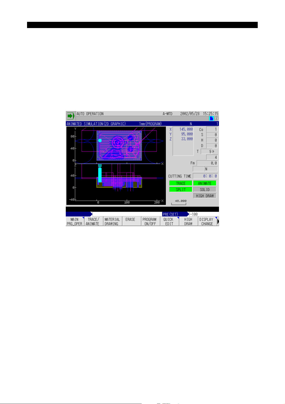
Eeoemm6f1012
Fig.1-2 Development Display
EIOEMM6F1003R01
Page 25
SECTION 1 REAL 3D ANIMATED SIMULATION
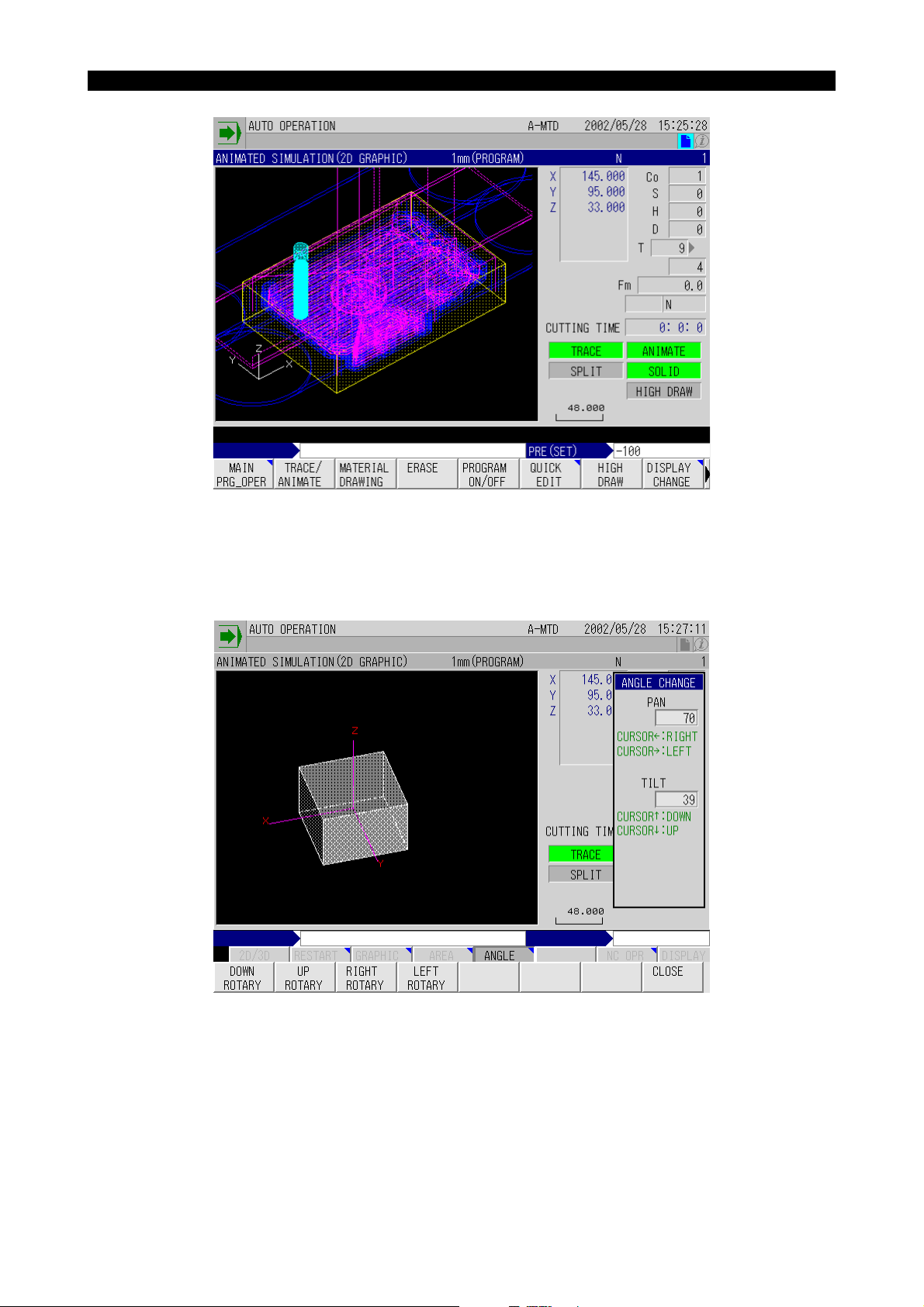
Fig.1-3 Solid View Display
4291-E P-8
EIOEMM6F1004R01
• In the display of solid figure, you can change the tilting angle and direction angle (pan) as
desired while viewing the displayed workpiece. This function enables checking for the progress
of machining in the desired direction.
Fig.1-4 Angle Change
EIOEMM6F1005R01
Page 26
SECTION 1 REAL 3D ANIMATED SIMULATION
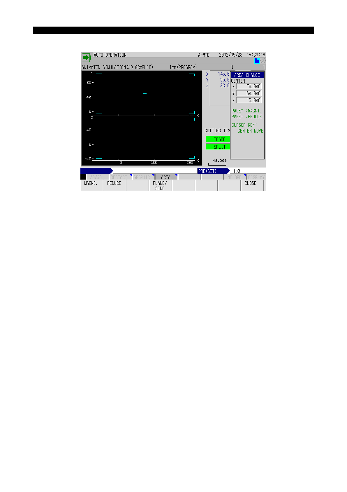
• Display range can be set as desired for both split view and solid view display.
4291-E P-9
Fig.1-5 Area Change
EIOEMM6F1006R01
• Pattern of painting differs depending on the depth of cut for the portion being machined.
• The function automatically determines the appropriate range of display according to the size of
the material.
• It is possible to set the shape of a cutting tool.
• Animation display is made at the actual cutting feedrate. By turning on the machine lock func-
tion, high-speed drawing is possible.
• The function to calculate the cutting time is provided.
• Simulation is also possible for operations including a rotary axis and five-face machining.
• Zero offset, cutter radius compensation, and 3D offset data are automatically calculated and
graphic is displayed including them.
• Operation intervention for return search and sequence restart operation.
Page 27
2-2. Animated Simulation Screen
2-2-1. Screen Configuration
4291-E P-10
SECTION 1 REAL 3D ANIMATED SIMULATION
The animated simulation screen configuration is shown below.
Fig.1-6 Graphic Display Screen Configuration
Eeoemm6f1013
EIOEMM6F1007R01
On this screen, tool paths and workpiece shape are displayed in the graphic display area. If graphic
display and text display overlap, display of text is given priority.
Page 28

SECTION 1 REAL 3D ANIMATED SIMULATION
2-2-2. Items Displayed on the Animated Simulation Screen
4291-E P-11
Eeoemm6f1014
Fig.1-7 Animated Simulation Screen
EIOEMM6F1008R01
X, Y, Z
Indicate the actual value of the individual axes in the work coordinate system.
Symbol of “-” is displayed for the axis for which the mirror image is ON.
S, Co, H, D
Indicate the spindle speed (S), the work coordinate system number (Co), the tool length offset number (H) and the cutter radius compensation number (D).
T
Indicates the actual tool number and the next tool number.
Fm
Indicates the feedrate.
CUTTING TIME
Indicates the cutting time.
Cutting time varies depending on whether or not the machine lock function is on.
Machine lock function ON: Length of timer required for axis movements is calculated at the completion of each block and added. In this calculation, the time spent for the execution of S, T, M commands and G04 is disregarded. Cutting time is calculated based on the feedrates that are obtained
by “programmed F value x override value (the value valid at the start of a block)”. For rapid feed
operation, time is calculated assuming override setting of 100%.
Machine lock function OFF: Total machine operating time is counted. Note that the cutting time data
is not cleared until the cycle start switch is pressed at the start of a program.
Page 29

4291-E P-12
SECTION 1 REAL 3D ANIMATED SIMULATION
TRACE/ANIMATE
Indicate the present mode of the graphic display screen.
• Both TRACE and ANIMATED highlighted
The tool path, material, and tool are displayed, and stock removal is also shown.
• Only TRACE highlighted
Only the tool path is displayed.
• Only ANIMATE highlighted
The material and tool are displayed, and stock removal is also shown.
The tool path is not displayed.
SPLIT/SOLID
Either SPLIT or SOLID is highlighted indicating the present display mode.
(scale)
The line segment and a number shown at the bottom of the graphic data display area indicate the
scale. The number shows the length, in the graphic coordinate system, of the displayed line segment.
Page 30
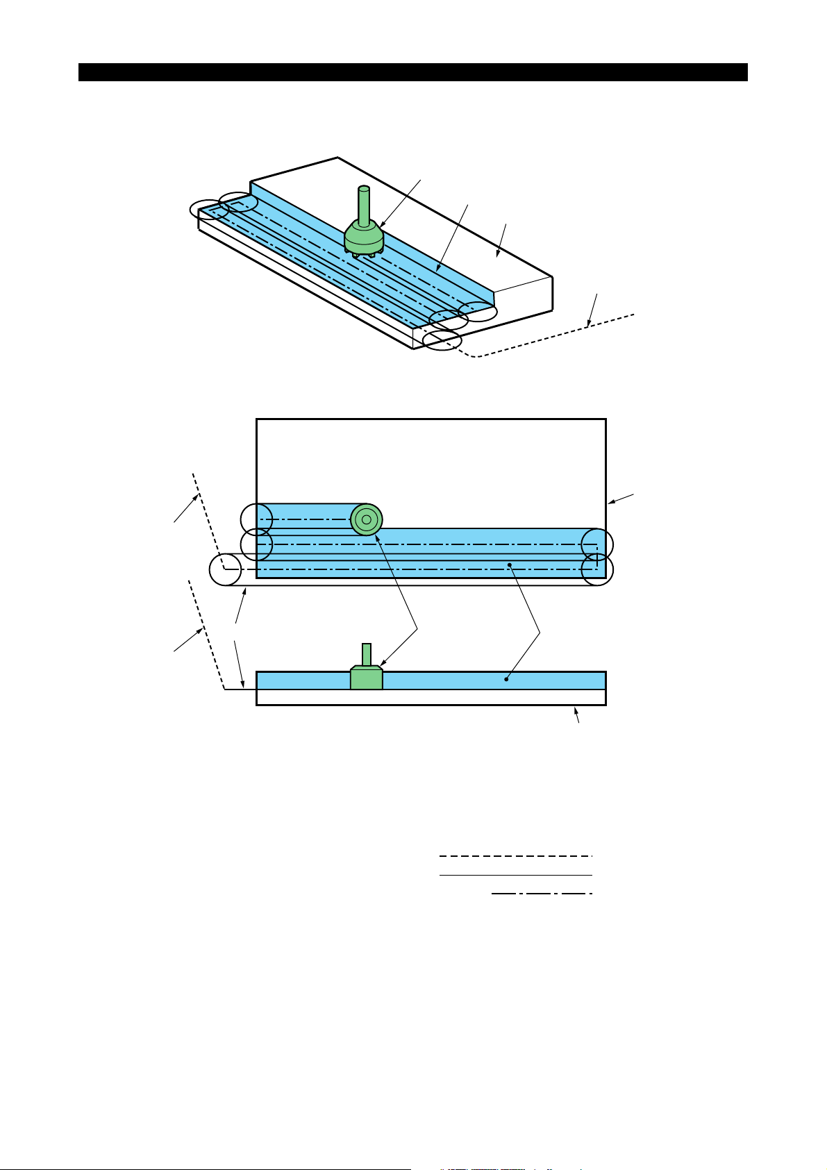
2-2-3. Graphic Display
4291-E P-13
SECTION 1 REAL 3D ANIMATED SIMULATION
Animation consists of tool path, envelope, enveloped figure, material, and position tool.
Position tool (2)
Envelope (3)
Material
Tool path (1)
Eeoemm6f1015
Fig.1-8 Graphic Display in Solid View Mode
(Top View)
Material
Tool path (1)
EIOEMM6F1009R01
Envelope (3) Enveloped figure (4)
Tool path (1)
Position tool (2)
(Side View)
Material
Fig.1-9 Graphic Display in Split View Mode
(1) Tool path
Shows the tool path.
Tool path is shown in the following three line types according to the mode of axis feed.
Rapid feed
Cutting feed
Jog feed
Short dash line
Solid line
Alternate short and long dash line
• Color designation for tool path is made at the GRAPHIC DATA window. Using different color
for tool paths of different axis feed modes is not allowed.
• Whether or not the tool paths of the individual feed modes (rapid feed for positioning, cutting
feed and jog feed) are drawn can be set at the GRAPHIC DATA window.
EIOEMM6F1010R01
EIOEMM6F1011R01
Page 31

4291-E P-14
SECTION 1 REAL 3D ANIMATED SIMULATION
(2) Position tool
Tool position is indicated by the symbol of tool which resembles the actual tool.
• The position tool is determined by the graphic system variable and the tool number of the
tool to be used.
• Color designation is possible for the position tool at the GRAPHIC DATA window.
• Whether or not the position tool is drawn can be set at the GRAPHIC DATA window.
• If animation is drawn with high enlarging ratio, or when a large-diameter tool is drawn, the
position tool could be displayed in incomplete form.
This portion is lost
Fig.1-10 Display of Position Tool
• Since the display priority of a position tool is higher than that of a material, it is always drawn
at the front side of the material although it is actually behind the material. See the illustration
below.
EIOEMM6F1012R01
Fig.1-11 Display of Position Tool (with Higher Display Priority)
EIOEMM6F1013R01
Page 32
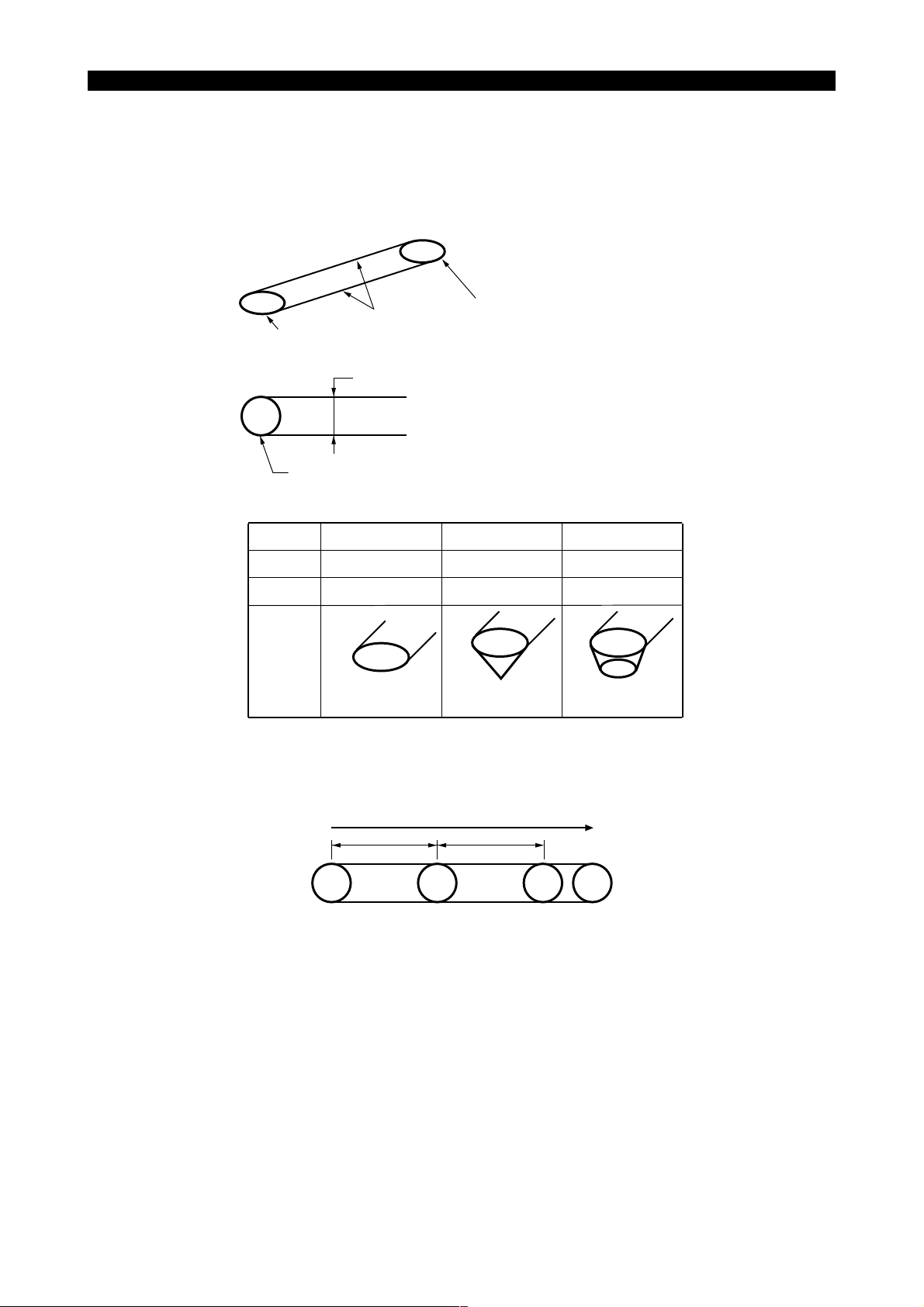
4291-E P-15
SECTION 1 REAL 3D ANIMATED SIMULATION
(3) Envelope
Shows the tool moving space that is defined by one block of commands using lines. Envelope is
displayed only in the cutting mode (cutting feed, jog feed).
• Envelope consists of width lines that indicate the tool moving width and tool circles that indicate the start/end of a block. Width and tool circle shape are determined according to the
graphic system variables of the tool number of the tool to be used.
Width lines
Tool circle
Determined by the graphic system tool diameter.
Determined by the graphic system variables
(tool diameter, nose angle, edge diameter).
Tool
Diameter
Nose Angle
edge diameter
Shape
0 0 0
180
free 0 0
Circle Cone Truncated cone
Fig.1-12 Determination of Envelope
Tool circle
0 < θ < 180 0 < θ < 180
EIOEMM6F1014R01
• In jog feed operation, a tool circle is drawn in preset intervals of time.
S
Jog feed
S
Fig.1-13 Drawing Tool Circles
EIOEMM6F1015R01
• The color used for drawing a tool circle and whether or not a tool circle is drawn are designated at the GRAPHIC DATA screen.
[Supplement]
Graphic system variables can be set as desired in the designated range and not restricted by
the tool classification code numbers. In tool shape selection, however, tool shape may be automatically determined according to a tool classification code number.
For graphic system variables, refer to “NC Program Related to Animated Drawing” in this section.
Page 33

SECTION 1 REAL 3D ANIMATED SIMULATION
• The plane where an envelope is drawn is defined in the following manner.
a. A tool circle is drawn in the plane where the tool axis is normal. Width lines are drawn in
the plane that is designated by a G code (G17, G18, G19) for circular interpolation.
b. For other than circular interpolation, the width lines are drawn in the same plane as the
tool circle drawing plane. See the illustration below.
Width
E
Tool circle
S
lines
Tool circles
Fig.1-14 Envelope Drawing Plane
(4) Enveloped Figure
Shows the portion of material having been machined.
4291-E P-16
EIOEMM6F1016R01
• You can choose the desired pattern corresponding to the machining level from 42 kinds of
graduated painting patterns to identify the portions of the material. This is drawn only in the
cutting mode (cutting feed, jog feed) and not drawn in the solid view mode or if only side view
is displayed in the split view mode. In the split-display mode, it is not displayed if a tool is
moving within the drawing range of a top view.
• Side view is drawn in a fixed pattern independent of the machining level.
• The shape of enveloped figure is determined by the graphic system variables of the tool to
be used.
(same as an envelope)
• Enveloped figure is not drawn if three or more axes move simultaneously.
Page 34

SECTION 1 REAL 3D ANIMATED SIMULATION
2-3. Coordinate Systems for Graphic Display
4291-E P-17
The coordinate system used for graphic display depends on the machine type, H type or V type.
Eeoemm6f1016
• Coordinate system for V type machines
The coordinate system where the Z-axis is taken as the vertical axis is assumed.
• Coordinate system for H type machines
The coordinate system where the Y-axis is taken as the vertical axis is assumed.
Coordinate system for V type machines
The coordinate system where the Z-axis
is taken as the vertical axis is assumed.
Spindle head
Z-axis
Z-axis table
Y-axis
Z-axis
Saddle
Coordinate system for H type machines
The coordinate system where the Y-axis
is taken as the vertical axis is assumed.
Spindle head
Rotary table
Y-axis
Z-axis
Table
X-axis
Saddle
Z
X
Y
X
Z
X
Y
Possible selection of planes
Y
Z
Y
: Split display planes
Z
Z
Y
X
X
Z
X
Y
Fig.1-15 Coordinate Systems for Graphic Display
EIOEMM6F1017R01
Page 35

4291-E P-18
SECTION 1 REAL 3D ANIMATED SIMULATION
Possible planes for graphic display are indicated on the following pages. These planes are grouped
by the tool axis, which is indicated by the arrow symbol (←).
A pair of planes shown in the corner enclosed by short dash lines is for split display.
Type V Type H
Y
Y
X
Y
Y
Z
Vertical axis (V)Horizontal axis (front) (HF)
Y
Z
Y
Z
X
Z
X
Y
Z
X
Z
X
ZZ
X
Z
X
X
X
X
Y
X
Y
X
Y
Y
Z
Y
Z
Z
X
Y
Z
Z
Z
Y
Y
YY
Z
X
Z
X
X
Y
EIOEMM6F1018R01
X
Page 36

SECTION 1 REAL 3D ANIMATED SIMULATION
Type V Type H
4291-E P-19
Z
Horizontal axis (left) (HL)Horizontal axis (back) (HB)
Y
Z
Y
Y
Z
X
Y
X
X
Z
X
X
X
X
Z
Y
Z
Y
Y
X
Z
X
Y
Z
Z
Y
Y
Z
X
Z
Z
Z
X
Y
Z
YY
X
X
Z
Z
YY
Z
Y
ZZ
Y
X
Z
EIOEMM6F1019R01
X
Z
Y
Horizontal axis (left) (HR)
Type V Type H
Y
X
XY
Z
ZZ
Y
XXY
Z
X
X
Z
X
Y
Z
YY
Z
Z
Z
X
EIOEMM6F1020R01
Page 37

2-4. Function Menus
4291-E P-20
SECTION 1 REAL 3D ANIMATED SIMULATION
The items in the function menus displayed on the ANIMATED SIMULATION screen are shown
below.
[Supplement]
To call the desired function menu, press the [EXTEND] key to the right of the [F8] key.
The following describes the function menu items.
TRACE/ANIMATE
MATERIAL DRAWING
ERASE Erases the tool path and the material shape drawn on the graphic screen.
HIGH DRAW Switches ON or OFF the high-speed drawing.
PROGRAM ON/
OFF
2D/3D CHANGE Switches the graphic display mode to 3D animation.
LOAD ON/OFF Displays the load during cutting.
TOOL ON/OFF Displays the shape and status of the tool being used.
SPLIT/SOLID
AUTO SCALE Executes automatic scaling processing.
GRAPHIC DATA Displays the pop-up window that is used for setting the graphic data.
AREA CHANGE Displays the pop-up window that is used for changing the display area.
ANGLE CHANGE
Selects the graphic display mode from among the following three modes
of display; TRACE/ANIMATE mode, TRACE mode, ANIMATE mode
Displays the registered material shape.
Displays the program source to be simulated.
Switches the mode of display between split view and solid view.
(2D animation only)
Displays the pop-up window that is used for changing the projection angle
(angle of view).
Eeoemm6f1017
EIOEMM6F1021R01
Page 38

2-4-1. Trace/Animate
4291-E P-21
SECTION 1 REAL 3D ANIMATED SIMULATION
The comment at the top of the graphic data display area changes cyclically as shown below each
Eeoemm6f1018
time function menu [F2] (TRACE/ANIMATE) is selected.
TRACE
AB
TRACE
TRACE
ANIMATEANIMATEANIMATE
C
Fig.1-16 Selection of Display Mode by TRACE/ANIMATE Function Menu
EIOEMM6F1022R01
A:Displays only tool path.
B:Displays only animation (material, enveloped figure, envelope, position tool)
C:Displays both tool path and animation.
This function menu is only used for selecting the display mode and not used for erasing or stopping
drawing.
This menu is valid in both solid view and split view display.
Fig.1-17 Screen Display by TRACE Selection
EIOEMM6F1023R01
Page 39

SECTION 1 REAL 3D ANIMATED SIMULATION
Fig.1-18 Screen Display by ANIMATE Selection
4291-E P-22
EIOEMM6F1024R01
Fig.1-19 Screen Display by TRACE/ANIMATE Selection
EIOEMM6F1025R01
Page 40

2-4-2. Tool Status
4291-E P-23
SECTION 1 REAL 3D ANIMATED SIMULATION
The tool status can be checked using the tool window called when [F4] (TOOL ON/OFF) is selected
from the function menu.
Fig.1-20 Tool Window
Eeoemm6f1019
EIOEMM6F1026R01
The tool window is displayed and cleared alternately each time [F4] (TOOL ON/OFF) is selected.
The contents displayed in the tool window are applicable in common to split view and solid view.
Page 41

2-4-3. Simulation Program
4291-E P-24
SECTION 1 REAL 3D ANIMATED SIMULATION
The program source to be simulated is displayed overlapping the graphic display when [F5] (PROGRAM ON/OFF) is selected from the function menu.
Fig.1-21 Display of Program Source
Eeoemm6f1020
EIOEMM6F1027R01
The program source is displayed and cleared alternately each time [F5] (PROGRAM ON/OFF) is
selected.
Sequence search is possible for the displayed program source using the cursor keys in the same
manner as using a program displayed in the program display screen.
Page 42

2-4-4. Material Drawing
4291-E P-25
SECTION 1 REAL 3D ANIMATED SIMULATION
When [F3] (MATERIAL DRAWING) is selected, the materials assigned the same conditions (spindle
Eeoemm6f1021
position and rotary axis) set at the GRAPHIC DATA window are searched from the registered materials in the ascending order of the registered numbers. The material found first is drawn after the
graphic screen is cleared.
GRAPHIC DATA
Spindle position
Rotary axis
HL
C0
Search
The material registered by No. 8 is drawn.
Registered Materials
Spindle position
No.
1
2
3
4
5
6
7
8
9
10
V
V
HR
HR
HF
HB
HL
HL
V
HL
Rotary axis
C 10
C 20
C 0
C 5
∗
C 25
C 90
C 0
C 0
C 0
No. 10 and No. 8 have the same
conditions, but drawing of No. 8
is not displayed because it has
a lower registration number.
EIOEMM6F1028R01
Material drawing processing is ignored in the following cases.
• Materials assigned the same conditions are not registered.
• Animation speed over state
• “Material drawing” is set for “NONE” in the setting of graphic data
This operation is common to split and solid view.
2-4-5. Erase
When [F4] (ERASE) is selected, path (tool path, material, envelope, enveloped figure) and material
shape are erased.
If it is selected in the animation speed over alarm state, the animation speed over state is cleared.
This operation is common to split view and solid view.
Eeoemm6f1022
Page 43

2-4-6. GRAPHIC DATA
4291-E P-26
SECTION 1 REAL 3D ANIMATED SIMULATION
When [F1] (GRAPHIC DATA) is selected, the GRAPHIC DATA pop-up window is displayed.
Environment for graphic drawing is set at the GRAPHIC DATA pop-up window.
The GRAPHIC DATA pop-up window may be called from the split view display and the solid view display. If it is called from the split view display, it shows the items to set the graphic drawing environment related only to the split view and those common to the split view and solid view. Similarly, if it is
called from the solid view display, it shows the items to set the graphic drawing environment related
only to the solid view and those common to the solid view and split view.
[Supplement]
The GRAPHIC DATA window consists of six data setting pages.
Page 4 and succeeding pages contain the items that are not used frequently. If “PAGE LIMIT” is set
for “EXIST” displayed in page 3, pages 4 and later are not displayed.
Data setting method is described below.
Eeoemm6f1023
Selection of input fields
To change the data setting pages, use the page keys.
To select the data input field within the same data setting page, use the cursor keys.
Inputting the data
For inputting the data, either the value to be set is selected or a numeric value is directly input.
• Input by selection
When the data item requires you to select the appropriate value, [F1] (MENU) is displayed in
the function menu.
Select [F1] (MENU) to display the selection items in the function menu. The item to be input
should be selected from the displayed selection items.
• Direct numeric value input
When the data item requires direct input of a numeric value, use the function menu ([F1] (SET)
and [F2] (ADD)) as needed.
Select the function menu first, input the numeric value and press the WRITE key.
The function menu items provide the following function.
[F1] (SET) The input value (the value displayed in the input buffer area) is directly used
as the setting value.
[F2] (ADD) The input value (the value displayed in the input buffer area) is added to the
presently set value to be set.
Page 44
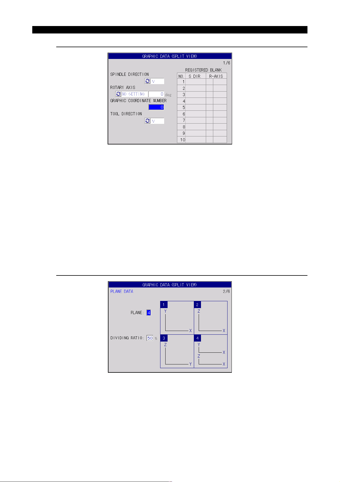
SECTION 1 REAL 3D ANIMATED SIMULATION
Graphic data window Page 1/6
Fig.1-22 GRAPHIC DATA Pop-up Window (Page 1/6)
SPINDLE DIRECTION
Select the spindle position from V, HF, HL, HB, and HR.
4291-E P-27
Eeoemm6f1024
EIOEMM6F1029R01
ROTARY AXIS
Select the rotary axis name and angle of the rotary axis for which simulation is executed.
GRAPHIC COORDINATE NUMBER
Specify the zero offset value of the graphic coordinate system by the work coordinate system offset
number.
TOOL DIRECTION
Select the tool direction from V, HF, HL, HB, and HR.
Graphic data window Page 2/6 (Split View)
Eeoemm6f1025
Fig.1-23 GRAPHIC DATA Pop-up Window (Page 2/6 - 1)
PAN
Specify the plane to be used for graphic display by a number (1 to 4).
Display is possible in a single plane (front, plan, side) and split display mode.
EIOEMM6F1030R01
Page 45

4291-E P-28
SECTION 1 REAL 3D ANIMATED SIMULATION
TILT
If split display is selected for PAN, specify the ratio of display area between the two planes. The set
value represents the display ratio of the plane vertical to the spindle to the entire display area.
[Supplement]
Two kinds of menu guide drawings are provided for PAN for H type and V type respectively. And five
kinds of menu guide drawing are available for each spindle position that is set in page 1/6.
Ten kinds of guide drawings are displayed in the following pages.
Type V Type H
Y
Y
X
Y
Y
Z
Vertical axis (V)Horizontal axis (front) (HF)
Y
Z
Y
Z
X
Z
X
Y
Z
X
Z
X
ZZ
X
Z
X
X
X
X
Y
Y
X
X
Y
Y
Z
Y
Z
Z
X
Y
Z
Z
Z
Y
Y
YY
Z
X
Z
X
X
Y
EIOEMM6F1031R01
X
Page 46

SECTION 1 REAL 3D ANIMATED SIMULATION
Type V Type H
4291-E P-29
Z
Horizontal axis (left) (HL)Horizontal axis (back) (HB)
Y
Z
Y
Y
Z
X
Y
X
X
Z
X
X
X
X
Z
Y
Z
Y
Y
X
Z
X
Y
Z
Z
Y
Y
Z
X
Z
Z
Z
X
Y
Z
YY
X
X
Z
Z
YY
Z
Y
ZZ
Y
X
Z
EIOEMM6F1032R01
X
Z
Y
Horizontal axis (right) (HR)
Type V Type H
Y
X
XY
Z
ZZ
Y
XXY
Z
X
X
Z
X
Y
Z
YY
Z
Z
Z
X
EIOEMM6F1033R01
Page 47

SECTION 1 REAL 3D ANIMATED SIMULATION
Graphic data window Page 2/6 (Solid View)
Fig.1-24 GRAPHIC DATA Pop-up Window (Page 2/6 - 2)
Set the direction of view for projection by PAN and TILT.
PAN
4291-E P-30
Eeoemm6f1026
EIOEMM6F1034R01
Indicates the angle in the horizontal plane, measured from the X-axis.
(0° to 359°)
TILT
Indicates the angle measured from the horizontal plane.
(-89° to 89°)
Graphic data window Page 3/6
Fig.1-25 GRAPHIC DATA Pop-up Window (Page 3/6)
Eeoemm6f1027
EIOEMM6F1035R01
The pop-up window is called from both the split view display and the solid view display. Although the
same pop-up window is displayed in either case, different values are displayed for the data setting
items.
CENTER
Specify the coordinate values of the center of the graphic drawing area by X, Y, and Z.
For X, Y, and Z, the values in the graphic coordinate system are used.
Page 48

4291-E P-31
SECTION 1 REAL 3D ANIMATED SIMULATION
WIDTH
Set the display area for graphic drawing in reference to the center of graphic drawing.
• Setting range of CENTER:
-9999.999 - 9999.999mm
• Setting range of WIDTH:
4.000 - 9999.999mm
UNIT EXEC RATE
The value set for this item is used for cylinder wall machining. By setting “;R” following a cylinder
radius, the value “2p x (set value) / 360∞ is calculated; this value is used as the factor to convert an
angular value [deg] into length [mm].
If the conversion coefficient set here does not agree with the conversion factor set in a program (the
value specified with address R in G175 block), precise graphic drawing is not obtained.
• Conversion coefficient setting range
0.010 ~ 99.999 (0.573R ~ 5729.577R) [mm/deg]
PAGE LIMI T
Select [F1] (MENU) and select the desired setting for this item.
• EXIST: Setting (display) is disabled for pages 4/6 to 6/6.
• NONE: Setting (display) is enabled for pages 4/6 to 6/6.
Graphic data window Page 4/6
Eeoemm6f1028
Fig.1-26 GRAPHIC DATA Pop-up Window (Page 4/6)
EIOEMM6F1036R01
Select [F1] (MENU) and set “EXIST” or “NONE” for each setting item by selecting the desired setting
from the function menu.
MANUAL FEED TRACE
Sets whether or not tool path for jog feed and manual rapid feed is drawn.
If “EXIST” is set, the path is drawn in alternate short and long dash line.
RAPID FEED TRACE
Sets whether or not tool path for rapid feed is drawn.
If “EXIST” is set, the path is drawn in short dash line.
Page 49

SECTION 1 REAL 3D ANIMATED SIMULATION
CUTTING FEED TRACE
Sets whether or not tool path for cutting feed is drawn.
If “EXIST” is set, the path is drawn in solid line.
ENVELOP LINE
4291-E P-32
Tool circle
Tool path
Tool circle
Envelope
Tool path
Envelope
Tool circle
Tool circle
Fig.1-27 Envelope Drawing
EIOEMM6F1037R01
If “EXIST” is set, the envelope is drawn in solid line.
BLANK
Sets whether or not the blank is drawn.
TOOL
If “EXIST” is set, position tool is drawn in the graphic animation drawing area and the tool kind in the
tool kind drawing area.
ENVELOP FIGURE
If “EXIST” is set, enveloped figure is drawn when the position tool passes through the area where
material is drawn. In the area where material is not drawn, envelope is drawn.
Fig.1-28 Enveloped Figure Drawing
EIOEMM6F1038R01
Page 50

4291-E P-33
SECTION 1 REAL 3D ANIMATED SIMULATION
Graphic data window Page 5/6
Eeoemm6f1029
Fig.1-29 GRAPHIC DATA Pop-up Window (Page 5/6)
EIOEMM6F1039R01
Specify the color for each drawing. After selecting [F1] (MENU), select the desired color from the
colors displayed in pop-up function menu.
Graphic data window Page 6/6
Eeoemm6f1030
Fig.1-30 GRAPHIC DATA Pop-up Window (Page 6/6)
EIOEMM6F1040R01
FRAME MOVING AREA CHANGE (dot)
Set the distance (dot unit) the scale frame moves at each pressing of the page key after selecting
[F2] (AREA CHANGE).
The frame moves by the set number of dots.
EIOEMM6F1041R01
ANIMATION COMMAND OUTPUT INTERVAL (dot)
Sets the distance (dot unit) the nose of the tool moves to determine the smoothness of simulation
drawing.
Page 51

RATIO OF ROOM AREA IN AUTO SCALE (%)
Set the margin of the drawing area that is obtained by the selection of [F7] (AUTO SCALE) as the
ratio to the material.
ANGLE CHANGE PITCH
Set the angle of rotation that corresponds to rotation by one pressing of a cursor key in the mode
selected by pressing [F3] (ANGLE CHANGE).
2-4-7. AUTO SCALE
4291-E P-34
SECTION 1 REAL 3D ANIMATED SIMULATION
When AUTO SCALE is selected, the material that is assigned the same spindle position and the
rotary axis set at the GRAPHIC DATA window is searched from the registered materials, the graphic
drawing area is automatically calculated and determined based on the material data.
If necessary, margin can be taken around the material. This area can be set by percent to the material drawing area at the GRAPHIC DATA window.
The auto scale function is valid only for the display given when automatic scaling is executed.
If the material assigned the same conditions is not registered, “No blank data” error occurs.
2-4-8. HIGH DRAW
The high-speed drawing executes animated simulation at high speed.
This function is valid when the machine lock function is ON in the automatic or MDI operation mode.
Each time [F7] (HIGH DRAW) is selected, high-speed drawing mode is turned on and off.
In the HIGH DRAW mode, animated drawing is executed for each block and path, envelope and
enveloped figure are drawn in this order. The position tool is not drawn.
The HIGH DRAW mode is cleared when the NC is reset or the program end command is executed.
[Supplement]
1) In the HIGH DRAW mode, G00 mode movement is executed in linear interpolation like G01.
Therefore, the drawn path differs from the actual tool path.
2) In the HIGH DRAW mode, drawing is given at the center of the screen.
3) The 3D arc (includes G02 and G03 in the 3D coordinate system) is expressed in a line that connects the start and end points of the arc if the NC is started in the HIGH DRAW mode or restart
search.
Eeoemm6f1031
Eeoemm6f1032
Page 52

2-4-9. AREA CHANGE
4291-E P-35
SECTION 1 REAL 3D ANIMATED SIMULATION
The area change function allows the drawing area where graphic is displayed to be set while viewing
graphic display. The AREA CHANGE pop-up window may be called from the split view display and
the solid view display. If it is called from the AREA CHANGE display, it shows the items to set the display area of the split view and if it is called from the solid view display, it shows the items to set the
display area of the solid view.
The results of area change processing are displayed on the AREA CHANGE pop-up window.
Eeoemm6f1033
Fig.1-31 AREA CHANGE Pop-up Window
(1) Area Change in Split View Display
Change the drawing area by moving the scale frame and the view point marker (+) using the
page keys and the cursor keys.
The scale frame is enlarged or reduced around the view point marker according to the selection
of function menu [F1] (MAGNI.) and [F2] (REDUCE) or the pressing of the page keys.
If a key is held pressed, the scale frame is continuously enlarged or reduced.
• [F1] (MAGNI.) or page key (p): Enlarge (object in narrower range is drawn.)
• [F2] (REDUCE) or page key (q): Reduction (object in wider range is drawn.)
[Supplement]
The drawing area may be enlarged up to 10 times the present range. However, it cannot be
enlarged exceeding the limit of drawing area of 4.000 mm.
The drawing area may be reduced up to 1/10 times the present range. However, it cannot be
reduced exceeding the limit of drawing area of 9999.999 mm.
The scale frame moves around the center according to the pressing of a cursor key. The
direction of movement is the same as the direction represented by the cursor keys. The
scale frame can be moved continuously by holding the cursor key.
(2) Area Change in Solid View Display
Basic operation procedure is the same as that for area change in split view display.
EIOEMM6F1042R01
Page 53

2-4-10. ANGLE CHANGE
4291-E P-36
SECTION 1 REAL 3D ANIMATED SIMULATION
This function allows the direction of view to be set for solid view display by using the display of a
Eeoemm6f1034
cube. Rotate the view angle model (cube) to set the solid view angle.
Fig.1-32 Rotating the View Angle Model by Cursor Keys
EIOEMM6F1043R01
This operation is invalid while a split view is drawn.
The results of view angle change are displayed in the ANGLE CHANGE pop-up window.
Fig.1-33 ANGLE CHANGE Pop-up Window
EIOEMM6F1044R01
Page 54

4291-E P-37
SECTION 1 REAL 3D ANIMATED SIMULATION
The operation to change the PAN, and TILT is indicated below.
Procedure :
1 Use the right and left cursor keys to change the PAN (angle measured from the positive direc-
tion of the X-axis).
+Z
+Z
+Y
+X
+X
X-Y-Z solid view Z-X-Y solid view
+Y
Fig.1-34 Changing the PAN
EIOEMM6F1045R01
2 Use the up and down cursor keys to change the TILT (angle measured from the horizontal
plane).
+Z +Y
+X
+Z
+Y
+X
Fig.1-35 Changing the TILT
EIOEMM6F1046R01
Page 55

2-4-11. Tool Shape Definition
4291-E P-38
SECTION 1 REAL 3D ANIMATED SIMULATION
The tool shape to be displayed in animated simulation is managed by the TOOL SHAPE DEFINITION screen that is accessible in the tool data setting mode.
To display and set the tool shape data at the TOOL SHAPE DEFINITION screen, follow the procedure below.
Procedure :
1 Press the tool data setting key in the mode selection key.
The indicator lamp at the upper left corner of the tool data setting key lights and the tool data
setting mode is established.
2 Select [F8] (DISPLAY CHANGE) from the function menu.
The DISPLAY CHANGE pop-up window is displayed.
3 Select TOOL SHAPE in the DISPLAY CHANGE pop-up window.
The TOOL SHAPE DEFINITION screen is displayed.
Eeoemm6f1035
Fig.1-36 TOOL SHAPE DEFINITION screen
EIOEMM6F1047R01
In addition to the tool shape data, the TOOL SHAPE DEFINITION screen manages the tool
length offset and cutter radius compensation data. These data are not used, however, for animated simulation.
It is not necessary to set the tool length offset and cutter radius compensation data for animated simulation.
The setting items related to animated simulation are indicated below.
TOOL NO. Tool number of the selected tool (Display only)
TOOL NAME Tool name of the selected tool (Input possible)
(Tool shape display) Approximate shape of the selected tool
TOOL DIMENSION / D Tool diameter (Not displayed for some tool shape)
TOOL DIMENSION / A Tool angle (Not displayed for some tool shape)
TOOL DIMENSION / ND Tool edge diameter (Not displayed for some tool shape)
Page 56

4291-E P-39
SECTION 1 REAL 3D ANIMATED SIMULATION
4 Follow the steps below to set the tool shape data.
5 Select [F1] (SET) and input the tool number.
Select [F1] (SET) from the function menu, input a tool number and press the WRITE key. This
displays the tool shape data of the tool registered to the input tool number.
If a tool number for which no tool data has been registered is input, the tool shape unregistered
screen is displayed.
Fig.1-37 TOOL DEFINITION (Unregistered) Screen
EIOEMM6F1048R01
New Registration of Tool Shape
To register the tool shape newly, input an unregistered tool number to display the unregistered TOOL
DEFINITION screen and perform the steps indicated below.
Procedure :
1 Move the cursor to TOOL NAME and select a required tool kind.
2 Input the dimensions for D, A, and ND.
This completes the registration of a new tool.
[Supplement]
For the setting of tool length offset data and the cutter radius compensation data, refer to OPERATION MANUAL / DATA OPERATION, “Tool Data setting Operation” and “Tool Shape”.
Deletion of Registered Tool Shape
To delete the registered tool shape, display the data of the tool number to be deleted at the TOOL
DEFINITION screen and select “NO SELECT” for TOOL NAME item.
Eeoemm6f1036
Eeoemm6f1037
Page 57

SECTION 1 REAL 3D ANIMATED SIMULATION
2-5. NC Program Related to Animated Drawing
4291-E P-40
NC Codes Related to Graphic Display
NC Code Function Comment
DEF WORK[n]
~ END
DELETE WORK
[n]
SAVE The material shape definition
DRAW The material is drawn after delet-
CLEAR The graphic screen is deleted.
Material definition “start” declaration
Material definition “end” declaration
The material that is defined by the
data between the “start” and
“end” is registered to the number
indicated by “n”. If the material
shape is already registered to the
specified number, delete the registered shape before registering
the new shape.
The material definition data of the
material specified by the number
“n” is deleted.
data is backed up to the PBU file.
ing the graphic screen.
(The material is not drawn if the
material has not been registered.)
Eeoemm6f1038
[n]: Integer (1 to 10)
Omission of [n] indicates “1”.
The NC codes that are valid in the
blocks between the start and end
declaration are:
CYLINDR, CYLINDRI, ORIGIN,
DIREC, INDEX
[n]: Integer (1 to 10)
Omission of [n] indicates “1”.
NC Codes Valid in Blocks between DEF WORK [n] and END
NC Code Function Comment
ORIGIN Hn The work coordinate system in
which the material is defined is
specified by “n”.
INDEX
Angle
DIREC V
CYLNDR Used for registering a cylinder, tri-
CYLNDRI Used for registering a cylinder, tri-
A
B
C
HL
HR
HB
HF
The name and angle of the rotary
axis used for cutting the material
to be defined are indicated.
The direction of the tool rotating
axis (direction of cutting) used for
cutting the material to be defined
is indicated.
angle pole, or square pole.
angle pole, or square pole.
n: Work coordinate system number
Input for this NC code is not necessary if the rotary axis specification is not supported.
Angle: Integer (0 to 359)
V:Vertical axis
HL:Horizontal axis [left]
HR:Horizontal axis [right]
HB:Horizontal axis [back]
HF:Horizontal axis [front]
Absolute coordinate system
Relative coordinate system
Page 58

2-5-1. DEF WORK[n] ~ END
4291-E P-41
SECTION 1 REAL 3D ANIMATED SIMULATION
(Format) DEF WORK [n] ~ END, 1 ≤ n ≤ 10
Eeoemm6f1039
<Explanation>
Registers the material shape.
Material definition consists of the start declaration, registration procedure statement (see the INDEX
and DIREC items), shape command string, and end declaration.
<Example>
To register cylindrical material, having the center at (250, 0), bottom radius of 226, bottom height of
0 and top face height of 81, to registration No. 1 under the conditions that the cutting direction is V
and there is no rotary axis specification. For the definition, coordinate system number 1 is used.
DEF WORK [1] ............................. Material definition start declaration
DIREC V ............................. Registration procedure statement
ORIGIN H1 ............................. Shape command string
CYLNDR 0P, [250, 0] 226, 0, 81 ............................. Shape command string
END ............................. Material definition end declaration
[Supplement]
1) When defining the material shape, the work coordinate system where NC program is written is
used with the unit system fixed at "mm" or "0.1 inch".
2) Up to 32 kinds of materials can be registered using CYLNDR and CYLNDRI.
3) Up to 32 sets of ORIGN can be registered.
2-5-2. CYLNDR and CYLNDRI
The coordinate system used for defining a material with CYLNDR and CYLNDRI is changed according to the spindle position.
HL (horizontal axis "left") and HR (horizontal axis "right"): X → Z, Y → X, Z → Y.
HF (horizontal axis "front") and HB (horizontal axis "back"): X → Y, Y → Z, Z → X.
For example, if the following is defined as the material:
Cylinder 0P [-250, 0], 226, 0, 81 Cylinder
[-250, 0]: Center, 226: Diameter, 0, 81: Bottom heights
Then, the axis that corresponds to the set value for the center and the height is determined as
shown in the table below according to the data of the registration procedure statement "DIREC".
DIREC\ Center [-250, 0] Height [0, 81]
VX, YZ
HF Y, Z X
HL Z, X Y
HB Y, Z X
HR Z, X Y
Explanation is given below for the spindle position V (vertical spindle) unless otherwise specified.
Eeoemm6f1040
Page 59

2-5-3. DELETE WORK
4291-E P-42
SECTION 1 REAL 3D ANIMATED SIMULATION
(Format) DELETE WORK, 1 ≤ n ≤ 10
<Explanation>
Deletes the material definition data of the registration number "*".
<Example>
DELETE WORK
DELETE WORK[1]
This deletes the material definition data of registration number 1.
2-5-4. ORIGIN
(Format) ORIGIN Hn n: Work coordinate system number
<Abbreviated format>
OR
<Explanation>
Specifies the coordinate system by number "n".
This remains valid until ORIGIN or END is specified next. "H0" is assumed if nothing is specified.
Note that the allowable maximum value for "n" depends on the specification.
Although LP (last reference point) is replaced with the value in the new coordinate system, absolute
values are not changed.
Eeoemm6f1041
DELETE WORK[n], 1 ≤ n ≤ 10
Eeoemm6f1042
2-5-5. DIREC
(Format) DIREC V
<Explanation>
Indicates the tool rotating direction (cutting direction) for cutting the material to be defined.
If the machine does not have the spindle head index specification, specify "DIREC V".
Specify the horizontal axis position by HL, HR, HB, or HF in reference to the spindle position of the
spindle head.
DIREC HL
DIREC HR
DIREC HB
DIREC HF
(HL) (HR)
Offset reference
point (V position)
Eeoemm6f1043
HL (horizontal axis "left")
HR (horizontal axis "right")
HB (horizontal axis "front")
HF (horizontal axis "back")
EIOEMM6F1049R01
Page 60

2-5-6. INDEX
4291-E P-43
SECTION 1 REAL 3D ANIMATED SIMULATION
(Format) INDEX A, angle
<Explanation>
Indicates the name and angle of the rotary axis used for cutting the material to be defined.
Rotary axis name is A, B, or C, and angle should be specified in the range from 0 to 359 (integer).
2-5-7. CYLNDR
(Format) CYLNDR 0, [center of bottom face (xc, yc)], bottom face diameter D → (A)
(A) → Bottom face height: z1, Top face height: z2
(B) → Same as above
(C) → Same as above
<Abbreviated format>
CY
<Explanation>
Defines the shape of a cylindrical pole or hole. (Absolute value)
Eeoemm6f1044
INDEX B, angle
INDEX C, angle
Eeoemm6f1045
CYLNDR 0P, Same as above → (B)
CYLNDR 0H, Same as above → (C)
• 0 or 0P: Cylindrical pole
• 0H: Cylindrical hole
z
x
y
D
Bottom face diameter
z
2 : Bottom face height
z
1 : Bottom face height
(xc, yc)
Center of bottom face
EIOEMM6F1050R01
Page 61

2-5-8. CYLNDR
4291-E P-44
SECTION 1 REAL 3D ANIMATED SIMULATION
(Format) CYLNDR 3,
[apex of bottom face (x1, y1)], [apex of bottom face (x2,
y2)]
CYLNDR 3P, Same as above → (B)
CYLNDR 3H, Same as above → (C)
(A) → [apex of bottom face (x3, y3)], bottom face height z1, top face height z2
(B) → Same as above
(C) → Same as above
<Abbreviated format>
CY
<Explanation>
Defines the shape of a triangle pole or hole. (Absolute value)
• 3 or 3P:Triangle pole
• 3H:Triangle hole
z
y
z
2 : Top face height z2
1, y1)
(x
Eeoemm6f1046
→ (A)
x
(x
2, y2)
(x
z1 : Bottom face height
3, y3)
EIOEMM6F1051R01
Page 62

2-5-9. CYLNDR
4291-E P-45
SECTION 1 REAL 3D ANIMATED SIMULATION
(Format) CYLNDR 4,
[apex of bottom face (x1, y1)], [apex of bottom face (x2,
y2)]
Eeoemm6f1047
→ (A)
CYLNDR 4P, Same as above → (B)
CYLNDR 4H, Same as above → (C)
(A) → [apex of bottom face (x3, y3)], [apex of bottom face (x4, y4)], bottom face height z1, top face
height z2
(B) → Same as above
(C) → Same as above
<Abbreviated format>
CY
<Explanation>
Defines the shape of a square pole or hole. (Absolute value)
• 4 or 4P: Square pole
• 4H: Square hole
z
z2 : Top face height
4, y4)
y
x
(x
z
1 : Bottom face height
3, y3)(x1, y1)(x2, y2)
(x
EIOEMM6F1052R01
The rectangle at the bottom of the square pole is defined by connecting (x1, y1), (x2, y2), (x3,
y3), and (x4, y4) in this order. If lines intersect with each other or a rectangle with concave is
defined, the commands are invalid.
Page 63

2-5-10. CYLNDRI
4291-E P-46
SECTION 1 REAL 3D ANIMATED SIMULATION
(Format) CYLNDRI 0,
CYLNDRI
0P,
CYLNDRI
0H,
[reference point x, y], [relative center of bottom face
Dxc],
Same as above → (B)
Same as above → (C)
Eeoemm6f1048
→ (A)
(A) → [relative center of bottom face Dyc], Bottom face diameter D, Reference point Z, Relative
height of bottom face Dz1, Relative height of top face Dz2
(B) → Same as above
(C) → Same as above
<Abbreviated format>
CYI
<Explanation>
Defines the shape of a cylindrical pole or hole. (Relative value)
• 0 or 0P: Cylindrical pole
• 0H: Cylindrical hole
D : Bottom face diameter
y
Reference point
(x, y, z)
c
y
x
x c
Relative center of bottom face
z 2
: Relative height of top face
z 1
: Relative height of bottom face
z
Reference point
(x, y, z)
x
EIOEMM6F1053R01
Page 64

2-5-11. CYLNDRI
4291-E P-47
SECTION 1 REAL 3D ANIMATED SIMULATION
(Format) CYLNDRI 3,
CYLNDRI
3P,
CYLNDRI
3H,
[reference point x, y], [relative apex of bottom face Dx1,
Dy1],
Same as above → (B)
Same as above → (C)
Eeoemm6f1049
→ (A)
(A) → [relative apex of bottom face Dx2, Dy2], [relative apex of bottom face Dx3, Dy3], Reference
point z, Relative height of bottom face Dz1, Relative height of top face Dz2
(B) → Same as above
(C) → Same as above
<Abbreviated format>
CY1
<Explanation>
Defines the shape of a triangle pole or hole. (Relative value)
• 3 or 3P: Triangle pole
• 3H: Triangle hole
1
y
x 1
y 2
y 3
y
x
z
x
Reference point
(x, y, z)
Reference point
(x, y, z)
x 2
x 3
z 2
z 1
EIOEMM6F1054R01
Page 65

2-5-12. CYLNDRI
4291-E P-48
SECTION 1 REAL 3D ANIMATED SIMULATION
(Format) CYLNDRI 4,
CYLNDRI
4P,
CYLNDRI
4H,
[reference point x, y], [relative apex of bottom face Dx1,
Dy1],
Same as above → (B)
Same as above → (C)
Eeoemm6f1050
→ (A)
(A) → [relative apex of bottom face Dx2, Dy2], [relative apex of bottom face Dx3, Dy3], [relative apex
of bottom face Dx4, Dy4], Reference point z, Relative height of bottom face Dz1, Relative height of
top face Dz2
(B) → Same as above
(C) → Same as above
<Abbreviated format>
CY1
<Explanation>
Defines the shape of a square pole or hole. (Relative value)
• 4 or 4P: Square pole
• 4H: Square hole
y 3
x 3
y
x 4
x 2
y 1
y 2
y
4
x
Reference point
(x, y, z)
z
Reference point
x
x 1
z 2
z 1
EIOEMM6F1055R01
The rectangle at the bottom of the square pole is defined by connecting (x + Dx1, y + Dy1), (x +
Dx2, y + Dy2), (x + Dx3, y + Dy3), and (x + Dx4, y + Dy4) in this order. If lines intersect with
each other or a rectangle with concave is defined, the commands are invalid.
Page 66

2-5-13. System variables
4291-E P-49
SECTION 1 REAL 3D ANIMATED SIMULATION
In NC program, tool diameter, tool nose angle, tool edge diameter, and tool classification code num-
Eeoemm6f1051
bers are expressed as indicated below.
Variable Name Description Setting Range Comment
VTLTD [I] Tool diameter 0.000 ≤ * ≤ 9999.999
VTLNA [I] Tool nose angle 0.000 ≤ * ≤ 180.000
See Supplement 2.
VTLND [I] Tool edge diameter 0.000 ≤ * ≤ 9999.999
VTLIN [I]
Tool classification code number
1 ≤ * ≤ 7 See Supplement 3 and 4.
[Supplement]
1) Direct setting is possible for the system variables indicated above using the TOOL DIMENSION
screen in the tool data setting mode.
2) These system variables are used for drawing the position tool, envelope, and enveloped figure.
3) Total of 16 tool classification code numbers is provided. However, the maximum setting value is
"7" since tools are registered in the range of 1 to 7 presently. The relationship between the tool
classification numbers and tool names and the correspondence of the position tool and tool kind
are shown below.
Tool
Classification No.
Tool Mame Drill Tap Reamer Boring bar End mill Face millCenter drill
1234567
Tool Kind
Position Tool
4) System variables can be set by tool life management groups.
In this case, setting is made in "VGR** [G]" instead of "VTL** [I]".
EIOEMM6F1056R01
Page 67

2-6. Graphic Display
2-6-1. Display Operation
4291-E P-50
SECTION 1 REAL 3D ANIMATED SIMULATION
Graphic display of animated simulation is possible by calling the ANIMATED SIMULATION screen
Eeoemm6f1052
in each operation mode.
Start a program at this screen, and graphic display starts.
[Supplement]
1) If axis feedrate is too fast, or when animated simulation is executed with enlarged graphics, simulation processing may fail to catch up program execution speed. In this case, "Drawing speed
over" is displayed at the upper left of the screen and simulation processing stops in the three
steps.
Enveloped
Figure
×
−
−
−
Position Tool
×
×
−
−
EIOEMM6F1057R01
Normal
Speed over 1
Speed over 2
Speed over 3
Tool Path
×
×
×
−
Envelope
×
×
−
−
¥: Drawn
-: Not drawn
Material drawing stops if the drawing speed over error occurs. This state can be cleared by
selecting [F4] (ERASE) from the function menu.
2) To execute only animated simulation without performing actual machining, start the program in
the machine lock state or dry run state.
2-6-2. Return Search and Sequence Restart
The animated simulation function allows operation intervention for return search and sequence
restart.
Graphic display for these operations is indicated below.
(1) Return search
If return search is executed, tool path is drawn to the specified sequence at a high speed.
The point that corresponds to the actual position blinks.
(2) Sequence restart
When the [SEQUENCE RESTART] key is pressed, axes move to the restart point at a jog feedrate.
The blink point moves from the actual position to the restart point.
• Operation after sequence restart
Press the [CYCLE START] key and the program after the specified sequence is executed.
[Supplement]
Blink point is cleared when the NC is reset, M02 (M30) is executed, tool path is erased or
graphic data is changed.
Eeoemm6f1053
Page 68

SECTION 2 NC OPERATION MONITOR
SECTION 2 NC OPERATION MONITOR
4291-E P-51
The NC operation monitor function has two sub functions -NC HOUR METER function and WORK
COUNTER function.
The NC HOUR METER function counts and displays count and set data for the individual timers POWER ON TIME, NC RUNNING TIME, SPINDLE REVOLUTION TIME, CUTTING TIME and
EXTERNAL INPUT TIME.
The WORK COUNTER function has four work counters and displays the count and set data for the
individual counters - WORK COUNTER A, WORK COUNTER B, WORK COUNTER C and WORK
COUNTER D. Each of these counters may be used as desired.
The preset function is available for both the NC hour meters and work counters so that an alarm signal is output when the count data reaches or exceeds the preset data.
At the operation mode monitor screen, select [F7] (NC OPR MONITOR) from the function menu,
and the NC OPR MONITOR pop-up function window is displayed.
If the NC OPR MONITOR is not displayed in the function menu, press the ([EXTEND]) key to the
right of [F8] key.
The NC OPE MONITOR pop-function window consists of two pages (NC HOUR METER table and
WORK COUNTER table) and you can select the desired page by pressing the page keys.
Eeoemm6f2001
Page 69

1. NC Hour Meter
The NC HOUR METER table displays the following items.
POWER ON TIME Displays the total NC power ON time.
NC RUNNING TIME
SPINDLE REVOLUTION
TIME
CUTTING TIME
EXTERNAL INPUT TIME Displays the total time an external input signal has been on.
4291-E P-52
SECTION 2 NC OPERATION MONITOR
Eeoemm6f2002
Fig.2-1 NC OPR MONITOR Pop-up Window (2/2)
EIOEMM6F2001R01
Displays the total NC running time. Length of time the machine
operated in the machine lock state is not included.
Displays the total time the spindle has rotated.
Displays the total axis feed time controlled in the cutting mode.
Length of time the machine operated in the machine lock state is
not included.
Data is displayed in the unit of “hours : minutes : seconds”.
1-1. Setting the Count and Set Data
In the table, you can set a desired value for COUNT (counted) and SET (not counted).
To set the count and/or set value, select the desired input area by pressing the cursor keys.
It is possible to output an alarm signal by setting a desired value for SET; the alarm signal is turned
on when the COUNT data reaches or exceeds the preset value.
Set “0 : 0 : 0" for SET if output of an alarm signal is not necessary.
The maximum value that can be set for COUNT and SET is 9999 : 59 : 59.
The setting format is “hours : minutes : seconds”.
Example
0 : 28 : 59 (Always enter a colon as a delimiter.)
Eeoemm6f2003
Page 70

2. NC Work Counter
4291-E P-53
SECTION 2 NC OPERATION MONITOR
The NC OPE MONITOR pop-function window consists of two pages (NC HOUR METER table and
WORK COUNTER table) and you can select the desired page by pressing the page keys.
Fig.2-2 NC OPR MONITOR Pop-up Window (1/2)
The work counter table displays the count and set data of the individual work counters.
• WORK COUNTER A, B, C and D count at each execution of M02 or M30 to count the number
of finished workpieces.
• The conditions for the work counters to increase the count data are identical for all of the
counters. In machine lock state operation, the counters do not count.
• You can use the four counters as desired. Counting the finished workpieces by work counter A
and counting the total number of finished workpieces from the time the NC started operating, for
example.
Eeoemm6f2005
EIOEMM6F2002R01
2-1. Setting the Count and Set Data
In the table, you can set a desired value for COUNT (counted) and SET (not counted).
To set the count and/or set value, select the desired input area by pressing the cursor keys.
It is possible to output an alarm signal by setting a desired value for SET; the alarm signal is turned
on when the COUNT data reaches or exceeds the preset value.
Set “0” for SET if output of an alarm signal is not necessary.
The maximum value that can be set for COUNT and SET is 99999999.
Eeoemm6f2006
Page 71

4291-E P-54
SECTION 3 SYNCHRONIZED TAPPING / TORQUE MONITORING FUNCTIONS
SECTION 3 SYNCHRONIZED TAPPING / TORQUE
MONITORING FUNCTIONS
1. Synchronized Tapping Function
The synchronized tapping function controls the spindle and feed axis operations in synchronization
using the MCS drive unit to perform tapping.
1-1. Commands
1-1-1. Programming Format
GXYZRE
G : G84 / G284 for tapping operation
G74 / G274 for reverse tapping operation
G84 and G74 are also used to call a tapping cycle that uses a floating tapper. Whether
these G codes call a conventional tapping cycle or a synchronized tapping cycle is
determined by parameter setting.
X,Y : Tapping position
Z : Bottom level of tapping cycle
R:Point R level
E : Spindle start position at point R level (angle designation)
P : Dwell period at the bottom level
Q : Dwell period at the point R level in return cycle
F : Feedrate
S : Spindle speed
Eeoemm6f3001
P
F
Q
SM
Eeoemm6f3002
EIOEMM6F3001R01
Page 72

SECTION 3 SYNCHRONIZED TAPPING / TORQUE MONITORING FUNCTIONS
1-1-2. Details of Commands
4291-E P-55
(1) G Codes Calling a Tapping Cycle (G84, G284)
Whether G84 calls a conventional float tapping cycle or a synchronized tapping cycle is determined by the setting for NC OPTIONAL PARAMETER (SYNCHRONIZED TAPPING) “G84 /
G74 TAP MODE”. Even if the setting is made for synchronized tapping, it calls a float tapping
cycle if the synchronized tapping specification is not selected.
[Supplement]
This parameter is provided to allow a tapping cycle having been programmed using G84 / G74
to be used in the synchronized tapping mode without modifying the existing program. Accordingly, it is recommended to specify a tapping cycle in the conventional mode if you program it
using G84 / G74. Note that the setting for this parameter is disregarded if the synchronized
tapping specification is not selected and G84 / G74 tapping cycle commands are executed in
the conventional float tapping mode.
G284 is always executed in the synchronized tapping mode independent of the setting for NC
OPTIONAL PARAMETER (SYNCHRONIZED TAPPING) “G84 / G74 TAP MODE”.
(2) G Codes Calling a Reverse Tapping Cycle (G74, G274)
The tapping cycle mode called by G74 is determined according to the setting for NC OPTIONAL
PARAMETER (SYNCHRONIZED TAPPING) “G84 / G74 TAP MODE” as with G84.
G274 is always executed in the synchronized tapping mode independent of the setting for NC
OPTIONAL PARAMETER (SYNCHRONIZED TAPPING) “G84 / G74 TAP MODE” as with G284.
Float Tapping Synchronized Tapping
G84, G74 Usable Usable
G284, G274 Not usable Usable
Eeoemm6f3003
(3) Tapping Position (X, Y)
The X and Y coordinate values determine the tapping position.
If X and/or Y is omitted, the coordinate value(s) valid in the previous block are used.
(4) Bottom Level of Tapping Cycle (Z)
In the G90 mode, the command specifies the level in the selected coordinate system. In the
G91 mode, however, the bottom level must be specified by the distance from the point R level.
Designation of the bottom level may be omitted. If you omit the command, the bottom level is
determined according to the general rule for fixed cycles. (For the general rule for fixed cycles,
refer to the Programming Manual.)
(5) Point R Level (R)
The command specifies the level of point R.
Designation of the point R level may be omitted. If you omit the command, the point R level is
determined according to the general rule for fixed cycles.
(6) Spindle Start Position at Point R Level (E)
This specifies the cut-in start position at the start of a tapping cycle by the spindle angular position (absolute value). This command is valid only for a synchronized tapping cycle and disregarded for a float tapping cycle (designation of this command for a float tapping cycle does not
cause an alarm).
Designation of the spindle position data may be omitted. If you omit the command, the spindle
position is determined according to the general rule for hole machining data.
The command is treated as a modal command in a fixed cycle mode. If the command is omitted
and none of the spindle start position command has been designated after the entry to a fixed
cycle mode, the cutting start position is not controlled and the cutting starts from the actual
spindle position.
Page 73

4291-E P-56
SECTION 3 SYNCHRONIZED TAPPING / TORQUE MONITORING FUNCTIONS
(7) Dwell Period at the Bottom Level (P)
The command specifies the length of time the tool dwells at the bottom level. You may specify
the desired dwell period in the same manner as in the G04 mode operation.
Designation of the dwell period may be omitted. If you omit this command, the dwell period is
determined according to the general rule for a fixed cycle.
(8) Dwell Period at the Point R Level in Return Cycle (Q)
The command specifies the length of time the tool dwells at the point R level. The length of time
may be specified in the same manner as a P command explained in item (7) above.
Designation of the dwell period may be omitted. If you omit this command, the dwell period is
determined according to the general rule for a fixed cycle.
(9) Feedrate (F)
Specify axis feedrate to be applied to axis feed within the cutting feed areas in a cycle operation.
Determine the value so that Z-axis feed distance per revolution of the spindle equals the tap
thread pitch.
Feedrate may be calculated from the thread pitch of the tap (P) and the spindle speed (S). In
the feed per minute mode (G94), F = P * S and in the feed per revolution mode (G95), F = P.
Designation of the dwell period may be omitted. If you omit this command, the dwell period is
determined according to the general rule for a fixed cycle.
Designation of an F1-digit feed command will cause an alarm.
(10) Spindle Speed (S)
The command specifies the spindle speed (synchronized feed speed of the spindle) during tapping.
Designation of a spindle speed may be omitted. If you omit this command, the spindle speed is
determined according to the general rule for a fixed cycle. The gears for driving the spindle are
automatically determined according to the specified S value. When the fixed cycle mode is canceled, the gears for normal operation are selected depending on the S value.
[Supplement]
M40 to M43 are disregarded during a synchronized tapping fixed cycle operation.
(11) Spindle Gear Selection (M)
During a synchronized tapping operation, spindle drive gear range is automatically selected
meeting the spindle speed command value.
If the gear range selected automatically does not meet actual tapping operation, you can select
the desired gear range by specifying an M code.
M234:Selects the gear range meeting the specified spindle speed.
M235:Selects the second gear range for the spindle speed that is usually executed in the first
gear range.
M236:Selects the third gear range for the spindle speed that is usually executed in the first or
second gear range.
M237:Selects the fourth gear range for the spindle speed that is usually executed in the first,
second or third gear range.
[Supplement]
During synchronized tapping operation, gear range selection M codes (M40 to M43) are disregarded. They become valid when the synchronized tapping mode is canceled.
Page 74

SECTION 3 SYNCHRONIZED TAPPING / TORQUE MONITORING FUNCTIONS
1-2. Details of Synchronized Tapping Operation
4291-E P-57
Point R level
Point Z level
Operation 1) 2)
Return point level
Operation 3) 4)
Operation 5)
Operation 6)
Operation 9)
Operation 8)
Operation 7)
Fig.3-1 Synchronized Tapping Operation
Eeoemm6f3004
Rapid feed
Cutting feed
(synchronized
tapping feed)
EIOEMM6F3002R01
(1) Tapping Cycle Command (G84, G284)
1), 2) Positioning is executed at (X, Y) at a rapid feedrate.
At the same time, spindle drive gears are selected meeting the specified spindle speed
(S command), then the spindle stops.
If an M code is specified in the same block, gear range selection and spindle stop control
are executed after the completion of positioning and specified M code operations.
3), 4) Positioning is executed at the point R level at a rapid feed rate.
If the block includes an E command, spindle orientation is executed at point E in the
specified spindle rotating direction (in the direction of tapping).
5) With the spindle rotating in the CW direction, Z-axis feed is controlled in synchronization
with spindle rotation up to the point Z level.
6) At the point Z level, the Z-axis dwells for P seconds if a P command is designated.
7) With the spindle rotating in the CCW direction, Z-axis feed is controlled in synchronization with spindle rotation up to point R level.
8) At the point R level, the Z-axis dwells for Q seconds if a Q command is designated.
9) Positioning is executed at the return point level at a rapid feedrate.
In operation steps 5), 6) and 7), settings of feed override and spindle override are disregarded
and axis feed and spindle rotation are controlled assuming 100% for both of them.
In operation steps 5), 6) and 7), dry run operation is always disabled.
Page 75

4291-E P-58
SECTION 3 SYNCHRONIZED TAPPING / TORQUE MONITORING FUNCTIONS
(2) Reverse Tapping Cycle Command (G74, G274)
In comparison to the tapping cycle explained in item (1) above, operations are same as those in
the tapping cycle with an exception the spindle rotating direction in operations 4), 5) and 6) is
reversed.
[Supplement]
1) Although the spindle remains rotating at the completion of a tapping cycle that uses a float-
ing tapper, the spindle stops at the end of a synchronized tapping cycle.
2) If the NC is reset during a synchronized tapping cycle, the gears selected for the execution
of the synchronized tapping cycle remain selected. The gear range is automatically
selected meeting the spindle speed with M40 to M43 taken into account when the spindle
is started next by a spindle start command (M03, M04), a spindle orientation command
(M19, M118, M119), an S command, or manual spindle operation.
(3) Slide Hold
If the [SLIDE HOLD] button is pressed during the execution of operation 5), the spindle stops
immediately, the spindle rotation is reversed to CCW and the Z-axis moves up to the point R
level in the synchronized operation. The spindle stops when the Z-axis reaches the point R
level.
If the [SLIDE HOLD] button is pressed during the execution of operation 5), the Z-axis decelerates. If the distance for the Z-axis to decelerate before it stops is larger than the remaining distance to the point Z level, pressing of the [SLIDE HOLD] button is disregarded. The Z-axis
keeps moving to the point R level and it stops there.
If the [SLIDE HOLD] button is pressed during the execution of operation 6), 7), the Z-axis stops
after it has reached the R-point level.
If the start button is pressed in the above state (where the spindle stops at point R level), the
spindle and Z-axis perform synchronized feed again to the point Z level.
[Supplement]
The manual intervention key is invalid while the spindle stops at point R level in the SLIDE
HOLD mode.
Page 76

SECTION 3 SYNCHRONIZED TAPPING / TORQUE MONITORING FUNCTIONS
1-3. Notes on Synchronized Tapping Operation
4291-E P-59
(1) G284 and G274 call the fixed cycle mode and G80 is used to cancel the fixed cycle mode.
Besides G80, G00, G01, G02 and G03 also cancel the fixed cycle mode.
(2) Specify an F command when designating G284 or G274 after turning on the power, resetting
the NC or canceling a fixed cycle. The fixed cycle mode is not canceled if other fixed cycle is
called.
(3) Specify an S command when designating G284 or G274 after turning on the power or resetting
the NC. An S command must be specified in a preceding or the same block that contains G284
or G274.
Eeoemm6f3005
<Example>
S320
:
:
G284
(4) The feed override and spindle override functions are disabled while spindle rotation and axis
feed are synchronized.
(5) Whether or not the cycle stops at point R level in the single block state is determined according
to the setting (DOES, DOES NOT) for “SINGLE BLOCK STOP AT POINT R LEVEL” of NC
OPTIONAL PARAMETER (FIXED CYCLE).
(6) Since the gear range for synchronized tapping is used during the synchronized tapping mode,
the gear range is changed at the entry to the synchronized tapping mode.
(7) Mid-block sequence restart operation does not allow you to restart the program from the opera-
tion synchronized between the spindle and the Z-axis feed. Internal processing for sequence
restart cannot be stopped until the point R level is reached.
(8) In the STM lock or machine lock state, Z-axis feed is executed at the specified feedrate. In this
state, Z-axis commands are executed assuming that the spindle is rotating.
NOTICE
1) To restart the sequence from a block specified in the synchronized tapping mode, specify
a block that does not contain synchronized axis feed operation. If sequence restart is
made from such a block, the gear range may not be selected appropriately disabling synchronized feed.
2) Do not change the ON/OFF state of the STM lock in the synchronized tapping mode. Otherwise, gear range may not be executed appropriately or the spindle control may be
incorrect.
Page 77
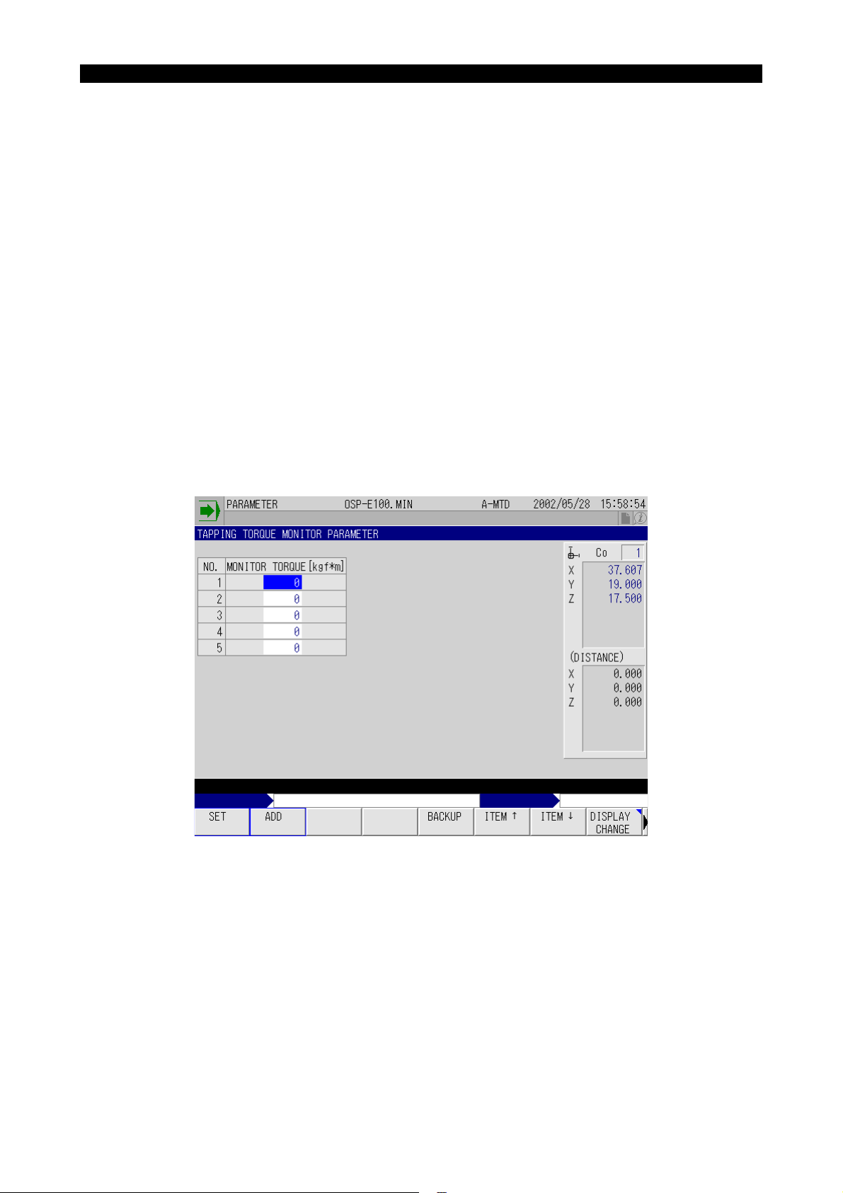
4291-E P-60
SECTION 3 SYNCHRONIZED TAPPING / TORQUE MONITORING FUNCTIONS
2. Torque Monitoring Function for Synchronized Tapping
This function monitors spindle load torque during synchronized tapping operation and causes alarm
B if the monitored torque exceeds the preset level.
2-1. Turning ON/OFF Torque Monitoring
M326:Torque monitoring OFF
M327:Torque monitoring ON
[Supplement]
The NC is in the M326 state when it is reset.
2-2. Parameters
The TAPPING TORQUE MONITOR PARAMETER screen is used to set the threshold level for monitoring the tapping torque. Setting is made in unit of “kgf·m”.
Five sets of parameters are provided and the parameter to be used for monitoring should be specified by its number using system variable VTMNO.
The parameter presently selected is displayed in yellow.
Eeoemm6f3006
Eeoemm6f3007
Eeoemm6f3008
Fig.3-2 TAPPING TORQUE MONITOR PARAMETER Screen
EIOEMM6F3003R01
Set a torque within the range recommended by the tool manufacturer (torque range in which a tap
can be used).
[Supplement]
1) From the standpoint of avoiding breakage of a tap, a smaller value will be effective. This, however, lowers cutting performance.
2) The selected parameter number is held even when the power is turned off.
3) If a parameter number for which “0” is set is selected, tapping torque is not monitored
Page 78
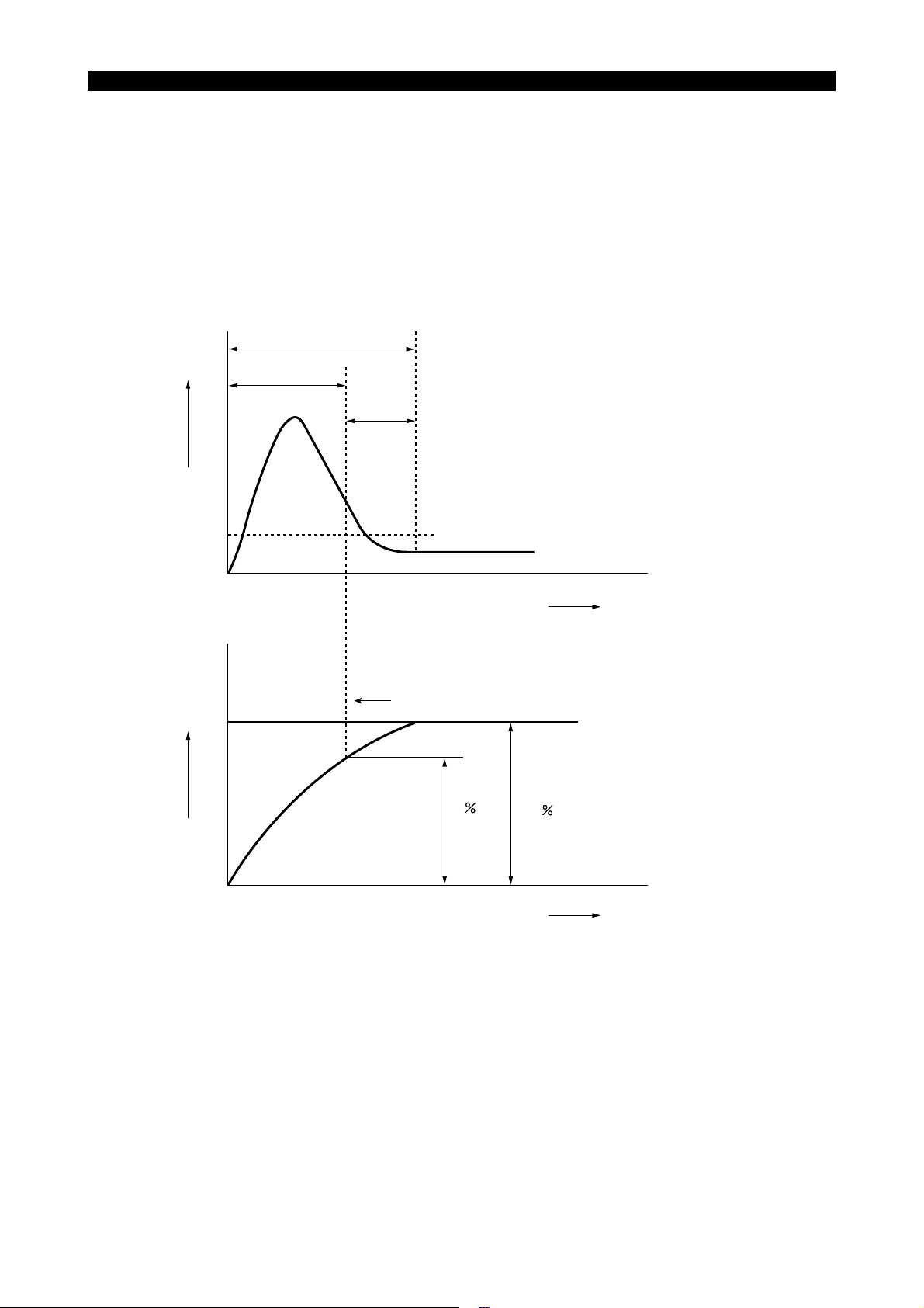
SECTION 3 SYNCHRONIZED TAPPING / TORQUE MONITORING FUNCTIONS
2-3. Setting the Immune Period
4291-E P-61
When starting the spindle from the state it is stopped, starting current flows the spindle motor that
Eeoemm6f3009
could cause the spindle torque to exceed the maximum allowable load. The overload state caused
by the motor start current is ignored in the two stages of processing indicated below.
• Overload state is ignored until the actual spindle speed reaches A% of the spindle speed specified by an S command.
• After the actual spindle speed has reached A% of the specified speed, the function further stays
immune for “t” [100 msec] to allow the spindle to rotate in the stabilized state. Torque monitoring
starts after the end of these two stages.
Start current
The function is immune to the overload state
T:
since the spindle rotation is unstable.
T
Spindle loadSpindle speed
t
t:
Spindle overload state is not checked within
this parameter-set period.
Threshold level for monitoring spindle torque
Stable spindle state
Time
Spindle is judged to be operating at a constant speed.
S command
A
100
Time
Fig.3-3 Overload at the Start-up of Spindle
EIOEMM6F3004R01
“A” and “t” are set for NC optional parameter (SYNCHRONIZED TAPPING).
TORQUE MONITOR START REVO. RATIO A Recommended value: 90%
TORQUE MONITOR DELAY TIME t Recommended value: 2 [100 msec] (200 msec)
Page 79
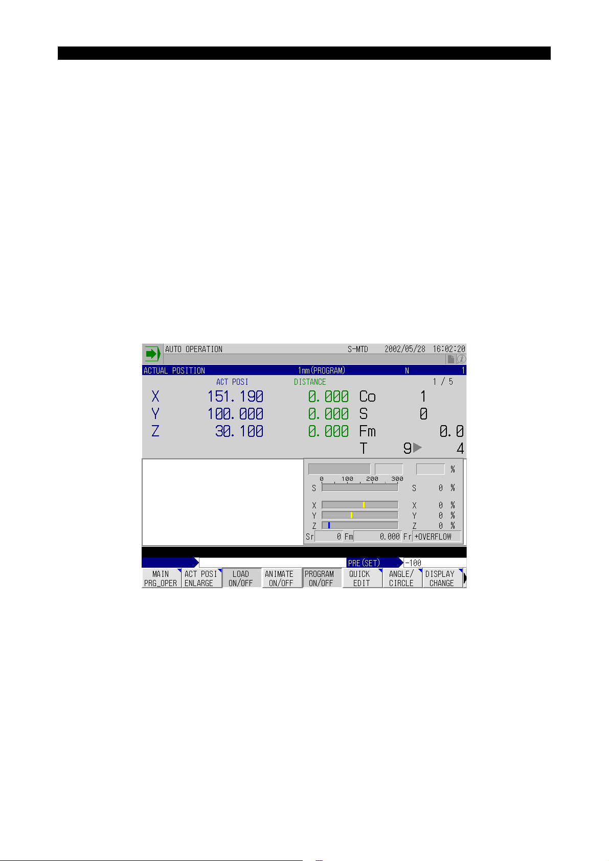
SECTION 3 SYNCHRONIZED TAPPING / TORQUE MONITORING FUNCTIONS
2-4. Torque Monitoring Method
4291-E P-62
If spindle torque exceeds the set value continuously for approximately “10 * n” [msec] continuously,
an alarm occurs and the following alarm message is displayed: Alarm B 2447 Synchronous tap's
torque low.
At the occurrence of the alarm, the Z-axis returns back to the point R level at the synchronized feed
mode and stops there.
Torque is continuously monitored until deceleration starts.
Value “n” above is set for NC optional parameter (SYNCHRONIZED TAPPING).
TORQUE LOW FOR SYNCHRONIZED TAPPING, NUMBER OF TORQUE OVER TIME
n Recommended value: 4 [times]
[Supplement]
If “0” is set for “n”, torque monitoring is not executed.
2-5. Display
The state of torque monitoring can be displayed on the LOAD MONITOR window that appears by
selecting [F3] (LOAD ON/OFF) from the function menu in each operation mode. The window can
also be displayed on the MAIN PROGRAM and SCHEDULE PROGRAM screens.
Eeoemm6f3010
Eeoemm6f3011
Fig.3-4 LOAD MONITOR Screen
EIOEMM6F3005R01
(a) The LOAD MONITOR meter displays the load in three colors: blue (load up to the continuous
rating of the spindle motor); yellow (over the continuous rating of the spindle motor and up to the
short-time rating); red (over the short-time rating of the spindle motor). The peak state will be
maintained. The LOAD MONITOR meter is reset each time the LOAD MONITOR window
appears.
(b) “TORQUE MONITOR” is displayed as torque monitoring begins, indicating that the torque is
being monitored. If the spindle load ratio exceeds the maximum load ratio of the torque, the
background color of the “TORQUE MONITOR” frame changes from green to yellow.
(c) The value displayed on the right side of “TORQUE MONITOR” is the tapping torque monitor
parameter number currently selected.
Page 80

SECTION 3 SYNCHRONIZED TAPPING / TORQUE MONITORING FUNCTIONS
(d) The maximum load ratio of the torque (%) on the right side of the parameter number described
in c) above is calculated by converting the set value of the “tapping torque monitor parameter”
based on the spindles continuous rating. The continuous rating of the spindle must therefore be
set with the parameter. For the set value, see the final specifications.
NC optional parameter (SYNCHRONIZED TAPPING)
SPINDLE RATED VALUE (SYNC. TAP)
<Example>
If the final specification document indicates the following, set “11000” for the parameter.
Spindle drive motor
VAC 11/15 kW (cont./30 min.)
• For the parameter, set the continuous rating after converting it into “W”.
[Supplement]
1) If no value is set for the parameter, torque is not monitored.
2) Spindle overload monitoring is not executed while synchronized tapping torque is moni-
tored. Note spindle overload monitoring using a meter relay is executed. Attachment load
monitoring is executed normally.
2-6. System Variables
4291-E P-63
(1) Synchronized Tapping Torque Monitor Parameter No.
[VTMNO]
• Read/write
• Setting range:
• Since VTMNO is backed up, the value specified before is valid if no value is specified newly.
Initial setting is “1”.
(2) Synchronized Tapping Torque Monitor Parameter
[VTMDT[n]]
• n: Parameter No. (1 to 5)
• Read only
Eeoemm6f3012
Page 81

SECTION 3 SYNCHRONIZED TAPPING / TORQUE MONITORING FUNCTIONS
3. Parameter
4291-E P-64
The parameters related to the synchronized tapping function are set using the NC OPTIONAL
PARAMETER (SYNCHRONIZED TAPPING) screen.
The screen displays the following parameters.
G84/G74 TAP MODE
(NC optional parameter (bit) No. 17, bit 7)
Sets whether G84 / G74 cycle is controlled in the float tapping mode or the synchronized tapping
mode.
FLOAT TAP:G84 / G74 cycle is controlled in the float tapping mode.
SYNC TAP:G84 / G74 cycle is controlled in the synchronized tapping mode.
Eeoemm6f3013
SPINDLE ORIENT ZERO OFFSET
(NC optional parameter (long word) No. 19)
Sets the offset data for spindle orientation controlled by the MCS drive unit.
Initial Setting Value Setting Range Setting Unit
0 0 ~ 359999 1/1000 [deg]
SPINDLE INDEX ANGLE AT RAPID FEEDRATE
(NC optional parameter (long word) No. 17)
Sets the position reduction rate with the E command when synchronized tapping is commanded.
Initial Setting Value Setting Range Setting Unit
Machine-dependent 0 ~ 359999 1/1000 [deg]
SPINDLE INDEX POSITION CHECK RANGE
(NC optional parameter (long word) No. 20)
Sets the range that causes an alarm if the spindle is out of it after spindle indexing.
Initial Setting Value Setting Range Setting Unit
0 0 ~ 20000 1/1000 [deg]
ZERO OFFSET(SYNC.TAP)
(NC optional parameter (long word) No. 15)
Sets the machine zero for spindle orientation executed according to an E command.
Initial Setting Value Setting Range Setting Unit
Machine-dependent 0 ~ 359999 1/1000 [deg]
For normal spindle orientation operation called by an RS command, the zero point of a position sensor is used as the reference for the control.
IN-POSITION CHECK VALUE(SYNC. TAP)
(NC optional parameter (long word) No. 16)
Sets the in-position check width for the positioning of the spindle in synchronized tapping operation.
Initial Setting Value Setting Range Setting Unit
Machine-dependent 0 ~ 359999 1/1000 [deg]
Page 82

SECTION 3 SYNCHRONIZED TAPPING / TORQUE MONITORING FUNCTIONS
SPINDLE RATED VALUE(SYNC. TAP)
(NC optional parameter (long word) No. 23)
Initial Setting Value Setting Range Setting Unit
0 110 ~ 99999999 W (watt)
RETURN SPEED OVERRIDE(SYNC. TAP)
(NC optional parameter (long word) No. 113)
Initial Setting Value Setting Range Setting Unit
01 ~ 200%
* “0” is regarded as 100%.
NUMBER OF TORQUE OVERTIME
(NC optional parameter (word) No. 21)
4291-E P-65
Initial Setting Value Setting Range Setting Unit
0 0 ~ 32 times 4
TORQUE MONITOR START REVO. RATIO
(NC optional parameter (word) No. 61)
Initial Setting Value Setting Range Setting Unit
0 0 ~ 100 % 90
TORQUE MONITOR DELAY TIME
(NC optional parameter (word) No. 62)
Initial Setting Value Setting Range Setting Unit
0 0 ~ 1000 100 msec 2 [msec] (200 msec)
Recommended
Value
Recommended
Value
Recommended
Value
Page 83

4291-E P-66
SECTION 4 UPGRADED SEQUENCE RESTART FUNCTION (MID-BLOCK RESTART FUNCTION)
SECTION 4 UPGRADED SEQUENCE RESTART FUNC-
TION (MID-BLOCK RESTART FUNCTION)
Eeoemm6f4001
NOTICE
This specification is closely related to the standard sequence restart function.
Before reading this chapter, you are required to thoroughly understand the “return search and
sequence restart” operation described in the Operation Manual.
If automatic operation is interrupted during the execution of a block, the standard sequence restart
function allows the cutting tool to return to the end point of the block immediately preceding the interrupted block. This mid-block restart function enables sequence restart from the point where the
operation was interrupted. In addition, the order of axis movements to return to the sequence restart
point can be set by assigning the priority to the axes.
Tool
3
5
2
4
Processed internally
Programmed path
Restart point
Designated restart block
Fig.4-1 Mid-block Sequence Restart Operation
EIOEMM6F4001R01
(1) Interruption of operation (halfway during the execution of a block)
(2) Manually retract the tool from the operation interrupted point.
(3) Manually return the tool near the operation interrupted point (restart point).
(4) Start the NC by pressing the [CYCLE START] button after return search operation. The com-
mands in the located block are internally processed up to the restart point.
(5) Press the [SEQUENCE RESTART] switch. The tool is positioned at the restart point at a jog fee-
drate.
(6) Press the [CYCLE START] button. The interrupted operation is resumed from the restart point.
In the internal processing of the located block, commands are processed without actual machine
operations like the operation in the machine lock state.
[Supplement]
If manual shift amount differs before and after operation interruption, the tool returns to the point
that is displaced from the operation interrupted point by this difference.
Page 84

SECTION 4 UPGRADED SEQUENCE RESTART FUNCTION (MID-BLOCK RESTART FUNCTION)
1. Sequence Restart Command
4291-E P-67
The RESTART pop-up window is used to set the command necessary for sequence restart operation.
Set the commands by following the procedure below.
Procedure :
1 Make sure that the automatic operation mode is selected with a main program selected cor-
rectly (main program has been read into the operation memory).
2 Press the [AUTO] mode selection key.
3 Select [F1] (MAIN PRG_OPER) from the function menu.
4 Select [F2] (RESTART) from the pop-up function menu.
The RESTART pop-up window is displayed.
Eeoemm6f4002
Fig.4-2 RESTART Pop-up Window
EIOEMM6F4002R01
Page 85

4291-E P-68
SECTION 4 UPGRADED SEQUENCE RESTART FUNCTION (MID-BLOCK RESTART FUNCTION)
5 Specify the return search method. Either input the sequence name or the block counter, or
select [F6] (LAST) from the pop-up function menu.
Restart by designating the restart sequence
In response to the input of a sequence name, optional designation items, A NUMBER OF
BLOCK BEYOND SEQUENCE NAME, REPEAT NUMBER, AXIS MOVEMENT ORDER, MIDBLOCK RESTART, and RETURN AXIS, are displayed for the input items.
If no options are desired, press the [SEQUENCE RESTART] key and the three axes simultaneously return to the start point of the sequence or block designated for sequence restart at a
jog feedrate.
Z
XY
Actual position
Sequence restart point
Fig.4-3 Axis Movements without Option Designation
EIOEMM6F4003R01
The optional designation items are described below.
• NUMBER OF RELATIVE BLOCKS BETWEEN SEQUENCE NAME AND RETURN
POINT
Enter the number of relative blocks between the sequence name and the return point.
• REPEAT NUMBER
Sets the number of times the specified sequence should be repeated. The maximum
allowable value is 9999.
If no value is set for this item, “1” is regarded.
• AXIS MOVEMENT ORDER
Sets the order of axis movements to return to the restart point.
Select one from “NONE”, “+X (X first move)”, “+Y (Y first move)”, “+Z (Z first move)”, “-X
(X last move)”, “-Y (Y last move)” and “-Z (Z last move)”. The axis moved returns to the
restart point in two steps.
“+X (X first move)”
“+Y (Y first move)”
“+Z (Z first move)”
“-X (X last move)”
“-Y (X last move)”
“-Z (X last move)”
The specified axis moves in the first pressing of the [SEQUENCE
RESTART] key. Other axes move in the second pressing of the
[SEQUENCE RESTART] key.
The specified axis moves in the second pressing of the
[SEQUENCE RESTART] key. Other axes move in the first pressing of the [SEQUENCE RESTART] key.
Page 86

4291-E P-69
SECTION 4 UPGRADED SEQUENCE RESTART FUNCTION (MID-BLOCK RESTART FUNCTION)
Z
“+Z” (Z first move)
XY
Return movement stops
here and the RUN lamp
blinks, waiting for the
pressing of the
[SEQUENCE RESTART] key.
“–Z” (Z last move)
Actual position
Sequence restart point
Return movement stops here and the
RUN lamp blinks, waiting for the pressing
of the [SEQUENCE RESTART] key.
Actual
position
Sequence restart point
Axis movement called by the first pressing
of the [SEQUENCE RESTART] key.
Axis movement called by the second pressing
of the [SEQUENCE RESTART] key.
Fig.4-4 Axis Movement Order Designation
EIOEMM6F4004R01
<Example>
SEQ. NAME: N100 AXIS MOVEMENT ORDER: -Z (Z last move)
Return search is executed for sequence name “N100” and, after the first pressing of the
[SEQUENCE RESTART] key, the axes other than the Z-axis return to the sequence
restart point. Pressing the [SEQUENCE RESTART] key again moves the Z-axis to the
sequence restart point.
BLOCK COUNTER: 127 AXIS MOVEMENT ORDER: +Z (Z first move)
Return search is executed for the 127th block sequence and, after the first pressing of
the [SEQUENCE RESTART] key, the Z-axis returns to the sequence restart point. Pressing the [SEQUENCE RESTART] key again moves the axes other than the Z-axis to the
sequence restart point.
• MID-BLOCK RESTART
Selection should be made from “NOTHING”, “MC POSIT” and “SLIDE HOLD”.
• RETURN AXIS
Input for this option designation is necessary only when you select “MC POSIT” for “MID-
BLOCK RESTART”.
Input any of “X”, “Y” and “Z”.
With this option designation, internal processing is executed from the block one block
ahead the specified sequence or block. The point where the actual position data of the
specified axis reaches the present machine position is taken as the restart point.
Page 87

4291-E P-70
SECTION 4 UPGRADED SEQUENCE RESTART FUNCTION (MID-BLOCK RESTART FUNCTION)
<Example>
Mid-block sequence restart operation by the following setting
AXIS MOVEMENT ORDER: +Z (Z first move), MID-BLOCK RESTART: MC POSIT,
RETURN AXIS: Y
Actual position
Z
Machine position
Designated return block
XY
<Internal processing> for these movements by [CYCLE START]
Fig.4-5 Designating the Restart Point
Restart by designating the block counter
In response to the input of a block counter, optional designation items, AXIS MOVEMENT ORDER, MID-BLOCK RESTART, and RETURN AXIS, are displayed for the input
items. Selection for these items are identical to those when a sequence name is used to
designate the sequence restart point selection.
Fig.4-6 RESTART Pop-up Window
6 Select [F7] (OK).
Return operation is executed up to the designated sequence.
Block preceding the designated
return block
EIOEMM6F4005R01
EIOEMM6F4006R01
In “return operation”, all programmed commands are executed as in normal operation with exceptions that function generation and external outputs for S, T, and M commands are not executed. Calling a subprogram, return from a subprogram, coordinate system shift, etc. are all executed.
The term “block count” indicates the count data of the sequences having been executed since the
program was started after the resetting of the NC. Control statements such as GOTO and CALL are
not counted. Since the block count data and the sequence name are not cleared by resetting the or
turning ON/OFF the power, they can be used for restoring the operation after resetting the NC, etc.
They are cleared at the first starting up of the operation.
[Supplement]
An attempt to execute mid-block sequence restart operation while a schedule program or a main
program is executed causes an error.
Page 88

SECTION 4 UPGRADED SEQUENCE RESTART FUNCTION (MID-BLOCK RESTART FUNCTION)
2. Sequence Restart Operation
4291-E P-71
Sequence restart from the designated sequence
Procedure :
1 Execute return operation to the designated sequence by refer to “Sequence Restart Com-
mand”.
2 Press the [SEQUENCE RESTART] key on the machine operation panel.
The axes move to the end point of the designated block at a jog feedrate.
3 Press the [CYCLE START] button and the programmed operation restarts.
Eeoemm6f4003
Sequence restart from the tool located position
Procedure :
1 Move any of X-, Y- and Z-axis to the desired restart position.
2 Execute return operation to the designated sequence by refer to “Sequence Restart Com-
mand”.
Set “MC POSIT” for MID-BLOCK RESTART and the name of the axis you have moved to the
desired restart position for RETURN AXIS.
3 Press the [CYCLE START] button.
Internal processing is executed from the designated position of the block one block ahead the
designated sequence. When the actual position data of the designated axis agrees with the
position data of the machine presently located, the SLIDE HOLD indicating lamp lights and the
internal processing ends.
The position defined by the actual tool position data is taken as the restart point.
4 Press the [SEQUENCE RESTART] key on the machine operation panel.
The axes move to the sequence restart point at a jog feedrate.
On completion of positioning the NC enters the slide hold state.
5 Press the [CYCLE START] button and the programmed operation restarts.
[Supplement]
The restart point is slightly shifted in the tool advancing direction from the desired restart point.
Page 89

4291-E P-72
SECTION 4 UPGRADED SEQUENCE RESTART FUNCTION (MID-BLOCK RESTART FUNCTION)
<Example 1>
N01 G00 X100. Y50. S300
N02 G56 Z -30. F200
N03 G01 G41 Y100. D08
(D08 = 10 mm)
N04 Y300.
N05 X300.
N06 Y100.
N07 X100.
N08 G40 X50.
N09 G00 G53 Z100. M05
N10 M02
X
300
200
100
Y
N04
N03
N08
N07
N01
0
Restart point
N05
N06
300200100
Fig.4-7 Example of Restart Operation and Program
EIOEMM6F4007R01
To return the axes to X130., Y310., Z-30. in the program above, follow the procedure indicated
below. Actually, the axes return to the position slightly shifted in the tool moving direction from
the desired position.
(a) Move the X-axis to X130.0 position.
(Y- and Z-axis may be located at any position.)
(b) At the RESTART pop-up window, set the items as shown below and execute the return
search operation by pressing the WRITE key.
Fig.4-8 Setting Example
EIOEMM6F4008R01
(c) Press the [CYCLE START] button. Internal processing is executed for the end point
(X90. Y100. Z-30.) in the N03 sequence. Internal processing ends at a point slightly
shifted from the end point (X90. Y100. Z-30.) in the tool advancing direction with the
SLIDE HOLD indicating lamp lit.
The position defined by the actual tool position data is taken as the restart point.
(d) Press the [SEQUENCE RESTART] key and the Z-axis moves to the restart point at a jog
feedrate. The RUN lamp starts blinking after the completion of positioning.
Page 90

4291-E P-73
SECTION 4 UPGRADED SEQUENCE RESTART FUNCTION (MID-BLOCK RESTART FUNCTION)
(e) Press the [SEQUENCE RESTART] key again. The X- and Y-axis move to the restart
point at a jog feedrate and, on completion of positioning, the SLIDE HOLD indicating
lamp lights.
(f) Press the [CYCLE START] button to restart the programmed operation.
Sequence restart from a desired position in a program
Procedure :
1 Execute return operation to the designated sequence by refer to “Sequence Restart Com-
mand”.
Select “SLIDE HOLD” for MID-BLOCK RESTART item.
2 Press the [CYCLE START] button.
Internal processing is executed from the end point of the sequence one block ahead the designated sequence.
3 After the internal processing has advanced to the desired restart point, press the [SLIDE
HOLD] button.
The position defined by the actual tool position data is taken as the restart point.
4 To change the restart point, press the [CYCLE START] button. Since internal processing
restarts when the [CYCLE START] button is pressed, you can change the restart point as necessary. Press the [SLID HOLD] button after the internal processing has progressed to the
desired restart point.
5 If necessary, you can change the restart point as desired by repeating the cycle start and slide
hold operation.
6 Press the [SEQUENCE RESTART] key and the axes return to the restart point at a jog fee-
drate. When the axes reach the restart point, the NC enters the slide hold state.
7 Press the [CYCLE START] button and the programmed operation restarts.
Page 91

SECTION 5 WARM-UP FUNCTION
4291-E P-74
SECTION 5 WARM-UP FUNCTION
The warm-up function is provided to execute warm-up automatically. It automatically turns on the
power according to the calendar timer setting and executes the specially prepared warm-up program.
NOTICE
For details of a calendar timer, read the instruction manual of the calendar timer supplied with the
product. Note that setting and handling of the calendar timer will vary depending on the manufacturer and the type. Before reading the instruction manual, make sure that the manual supplied
with the machine is the one for the calendar timer used in the machine.
1. Storing Warm-up Program
To use the warm-up function, the warm-up program must be stored in the user are of memory
(MD1:) by the file name of “W.WAF”. For storing the warm-up program use the normal program storing procedure.
1-1. Program Format
The program format of the warm-up program is identical to the main program format; it begins with a
program name preceded by address character O and ends with M02 or M30.
<Example>
Eeoemm6f5001
Eeoemm6f5002
Eeoemm6f5003
O9999
S200 M3
VC128=50
G0 Z500
NA1
X-200 Y-200
X200
G4 F5
VC128=VC128-1
IF [VC128 GT 0] NA1
M5
M2
Y200
EIOEMM6F5001R01
Page 92

2. Operation
2-1. Outline of Operation
4291-E P-75
SECTION 5 WARM-UP FUNCTION
Set the cycle on and off time on the calendar timer according to the operation schedule.
(After turning on the cycle, allow at least three minutes before turning it off. For cycle off, refer to
items (2) and (3) in “Supplements”.)
The power is automatically turned on to the NC according to the calendar timer setting.
Approximately 90 seconds after the power on, the end buzzer sounds for the parameter set time.
When the buzzer stops sounding, the NC enters the automatic operation mode, and selects and
starts the warm-up program (file name: W.WAF, program name: as desired).
After the completion of the warm-up program (execution of M02 or M30, or pressing the reset button
on the operation panel), the NC automatically selects the program having been selected before
shutting the power off. (Whether or not the previously selected program is selected after the completion of the warm-up program is determined by parameter setting.)
2-2. Timing Chart
Calendar timer output
Control power
Operation end buzzer
Eeoemm6f5004
Eeoemm6f5005
Automatic selection
of warm-up program
Automatic selection
of warm-up program
Reset by M02 / M30,
or by pressing the
reset button
Automatic selection of
the program selected
before power shutting off
Timing Chart for Automatic Power ON by Calendar Timer
EIOEMM6F5002R01
Page 93

2-3. Supplements
4291-E P-76
SECTION 5 WARM-UP FUNCTION
(1) After the completion of the warm-up program, the program selected last by the operation at the
operation panel is automatically selected. Therefore, if the warm-up program (file name:
W.WAF) was selected at the operation panel before shutting off the power, W.WAF is selected
again after the completion of the warm-up program.
(2) Even if the calendar timer output is turned off during the execution of the warm-up program, the
warm-up program is continuously executed.
(3) An alarm occurs if the W.WAF file does not exist in the memory when the power is automati-
cally turned on according to the setting on the calendar timer. For details, refer to “Alarm”.
(4) After the power is turned on, keys on the operation panel (mode selection keys, function keys
and alphanumeric keys), cycle start button and external cycle start button are all disabled until
the warm-up program starts automatically. These keys and buttons are operative, however, if
the warm-up program file selection is impossible.
(5) If the [RESET] button is pressed during warming up, the program having been selected before
shutting off of the power is automatically selected. Note that this automatic selection is not possible if “NOT SELECT” is selected for THE PROGRAM SELECTED BEFORE THE POWER
OFF of NC optional parameter (AUTO SET AT NC RESET/POWER ON).
(6) If the calendar timer goes on after the position data is displayed on the screen with the power
turned on by an operator, the warm-up function does not operate.
(7) Completion of the warm-up program does not cause power shutoff if the automatic power shut-
off function is selected.
(8) While the warm-up program is running after the power was turned ON, “WARM-UP PROGRAM
RUNNING” is displayed.
Eeoemm6f5006
CAUTION
If the operator turns off the power once while the calendar timer output is on and then turns it
on, the warm-up program is executed again.
3. Parameter
In relation to the warm-up function, setting is required for the following parameter.
MC USER PARAMETER OPERATION END BUZZER TIMER
Set the buzzer sounding time using [F1] (SET) or [F2] (ADD).
Eeoemm6f5008
Page 94

4291-E P-77
SECTION 6 SIMPLIFIED LOAD MONITOR FUNCTION
SECTION 6 SIMPLIFIED LOAD MONITOR FUNCTION
The simplified load monitor function monitors the spindle load ratio and outputs the alarm signal if
the detected load ratio exceeds the parameter set value.
A total of five sets of parameters are used for this function and system variable VSLNO selects the
desired parameter set. M142/M143 turns the simplified load monitor function on/off.
Eeoemm6f7001
1. Setting for the Simplified Load Monitor Function
(1) Turning ON/OFF the Function
M142...Turns the simplified load monitor function ON
M143...Turns the simplified load monitor function OFF
(2) Selecting the Spindle Load Monitor Parameter Number
For monitoring the spindle load, “maximum load (LOAD MAX)”, “continuous load time (LOAD
TIMER)” and “monitor mode (MONIT. MODE)” are set for parameters and five sets of parameters are provided. To execute monitoring, one set of parameters must be selected in advance.
VSLNO... Monitor parameter number selection system variable
Since VSLNO is backed up, previous setting for this variable is used if VSLNO is not set for the
monitoring. If no value has ever been set for this variable, “1” is assumed.
(3) Ignoring Spindle Motor Start-up Current
At the start up of the spindle motor, the start-up current flows the motor drive circuit causing the
detected spindle load to exceed the set maximum load. To prevent the occurrence of an alarm
in this situation, the NC ignores the start-up current of the spindle motor by the two steps of processing indicated below.
Eeoemm6f7002
a) The function ignores the spindle overload state until the actual spindle speed falls within the
range 75% to 125% of the specified spindle speed (S command).
Page 95

4291-E P-78
SECTION 6 SIMPLIFIED LOAD MONITOR FUNCTION
b) After the spindle speed reaches the range 75% to 125% of the specified spindle speed (S
command), the function stays immune to the spindle load for the parameter-set length of
time to allow the spindle to rotate in the stable state.
Start-up current
The function is immune to
T1:
the overload state since the
T1
T2
spindle rotation is unstable.
Spindle overload state is
T2;
not checked within this
parameter-set period.
Spindle load meter pointerSpindle speed
Set value
Stable spindle state
Time
Spindle is judged to be operating
at a constant speed.
100%75%
S command
Time
Fig.6-1 Ignoring Start-up Current of Spindle Motor
EIOEMM6F7001R01
(4) Overload Monitoring Method
When the spindle reaches the constant speed and rotates in the stable state, with the monitor
parameter set by VSLNO and the monitor function turned on by M143, spindle overload monitor
begins.
If the actual spindle load exceeds the parameter set maximum load for the length of parameter
set time, the spindle overload alarm occurs.
Page 96

2. Screen Display
4291-E P-79
SECTION 6 SIMPLIFIED LOAD MONITOR FUNCTION
From the function menu of the initial display screen in any operation mode, select [F3] (LOAD ON/
OFF) to display the LOAD window, monitor the spindle load in the LOAD window.
The LOAD MONITOR window can also be displayed on the “MAIN PROGRAM” and “SCHEDULE
PROGRAM” screens in each operation mode.
Eeoemm6f7003
Fig.6-2 LOAD Window
EIOEMM6F7002R01
(a) The LOAD MONITOR meter displays the load in three colors: blue (load up to the continuous
rating of the spindle motor); yellow (over the continuous rating of the spindle motor and up to the
short-time rating); red (over the short-time rating of the spindle motor). The peak state will be
maintained. The LOAD MONITOR meter is reset each time the LOAD MONITOR window
appears.
(b) “LOAD MONITOR” appears after the immune period to ignore the start-up current is terminated
during monitoring (M143), indicating overload is being monitored. If the spindle load exceeds
the maximum load, the background color of the OVERLOAD MONITOR frame changes from
green to yellow.
(c) The value displayed on the right side of “LOAD MONITOR” is the spindle overload monitor
parameter number currently selected.
(d) The value displayed on the right side of the parameter number described in c) above is the max-
imum load of the spindle overload monitor parameter currently selected.
Page 97

3. Parameters
4291-E P-80
SECTION 6 SIMPLIFIED LOAD MONITOR FUNCTION
(1) Machine User Parameter (Spindle)
The parameter related to the simplified load monitor function is indicated below.
SPINDLE OVERLOAD ALLOWABLE TIME
Sets the time for the function to wait for the spindle stabilized state.
(Refer to “Setting for the Simplified Load Monitor Function”, item “Ignoring Spindle Motor Startup Current”.)
Initial Setting Value Setting Range
Machine dependent
value
(2) Spindle Overload Monitor Parameter
Here, “maximum load (LOAD MAX)”, “continuous load time (LOAD TIMER)” and “monitor mode
(MONIT. MODE)” are set.
0 ~ 6000 [0.01sec]
Eeoemm6f7004
No.
Selects one of five parameter sets by VSLNO. The selected parameter is displayed in yellow.
LOAD MAX
Sets the allowable maximum load ratio (%).
Initial Setting Value Setting Range
0 0 ~ 280[%]
LOAD TIMER
Sets the allowable length of time the spindle load may exceed the set maximum load. Setting is
made in unit of seconds.
Initial Setting Value Setting Range
0 0 ~ 120[sec]
MONIT. MODE
Sets the alarm level for the overload alarm.
Initial Setting Value ALARM-A
4. System Variables
(1) Spindle Overload Monitor Parameter No.
VSLNO
• Read/write
• Data value range: 1 to 5
• Since VSLNO is backed up, previous setting for this variable is used if VSLNO is not set for
the monitoring. If no value has ever been set for this variable, “1” is assumed.
(2) Spindle Overload Monitor Parameter
VSLDT[i, j]
i:Parameter No. (1 to 5)
j:1 = Maximum load, 2 = Allowable continuous load time, 3 = Monitor mode
* Read only
Eeoemm6f7005
Page 98

4291-E P-81
SECTION 7 EXTERNAL PROGRAM SELECTION FUNCTION
SECTION 7 EXTERNAL PROGRAM SELECTION FUNC-
TION
1. External Program Selection A (Pushbutton Type)
The external program selection function / external program selection A (pushbutton type) selects a
main or a schedule program using a pushbutton switch. When a pushbutton is pressed, the corresponding program is selected.
Eeoemm6f8001
1-1. Program Type (Main or Schedule Program) Selection
Which type of the program (main program or schedule program) should be selected may be determined by the setting for the parameter.
NC optional parameter (bit) No. 17, bit 5
Check box (checked):Schedule program
Check box (not checked):Main program
Eeoemm6f8002
1-2. Disabling the Selection of the Same Program
It is possible to disable the loading of the selected program if the program already existing in the
memory is selected.
This can save the program loading time.
NC optional parameter (bit) No. 17, bit 6
Check box (checked):Disables the loading of the same program.
Check box (not checked):Enables the loading of the same program.
Eeoemm6f8003
1-3. Program selection
Press the pushbutton switch corresponding to the desired program to select it.
Selection of a program is possible in the range from P1.MIN (or SDF) to P16.MIN (or SDF).
(Note that the number of selectable programs differs depending on the specification.)
On completion of program selection, the lamp lights corresponding to the selected program. The
lamp, if lit, indicates that the corresponding program is in the selected state.
1-4. Supplements
• Program selection is possible only in the automatic mode.
• Program selection buttons are inoperative when a program is being selected.
• Program selection is impossible if the NC is in an alarm state.
• An alarm occurs if the selected program is not found.
• An alarm occurs if program selection is attempted during machining.
• Program selection, if attempted during program editing or copying, is suspended until editing or
copying is completed.
Eeoemm6f8004
Eeoemm6f8005
Page 99

SECTION 7 EXTERNAL PROGRAM SELECTION FUNCTION
2. External Program Selection B (Rotary Switch Type)
4291-E P-82
The external program selection function / external program selection B (rotary switch type) selects a
main or a schedule program using a rotary switch. Select the desired program by turning the rotary
switch.
Eeoemm6f8006
2-1. Program Type (Main or Schedule Program) Selection
Which type of the program (main program or schedule program) should be selected may be determined by the setting for the parameter.
NC optional parameter (bit) No. 17, bit 5
Check box (checked):Schedule program
Check box (not checked):Main program
Eeoemm6f8007
2-2. Disabling the Selection of the Same Program
It is possible to disable the loading of the selected program if the program already existing in the
memory is selected.
This can save the program loading time.
NC optional parameter (bit) No. 17, bit 6
Check box (checked):Disables the loading of the same program.
Check box (not checked):Enables the loading of the same program.
Eeoemm6f8008
2-3. Program Selection
Turn the rotary switch to select the desired program.
Selection of a program is possible in the range from P1.MIN (or SDF) to P16.MIN (or SDF).
(Note that the number of selectable programs differs depending on the specification.)
On completion of program selection, the program selection lamp lights. The lamp lights if the
selected program agrees with the one set by the rotary switch.
2-4. Supplements
• Program selection is possible only in the automatic mode.
• Program selection rotary switch is inoperative when a program is being selected.
• Program selection is impossible if the NC is in an alarm state.
• An alarm occurs if the selected program is not found.
• An alarm occurs if program selection is attempted during machining.
• Program selection, if attempted during program editing or copying, is suspended until editing or
copying is completed.
Eeoemm6f8009
Eeoemm6f8010
Page 100

SECTION 7 EXTERNAL PROGRAM SELECTION FUNCTION
3. External Program Selection C (BCD Type)
4291-E P-83
The external program selection function / external program selection C (BCD type) selects a main or
a schedule program in response to the program number designated by the BCD input signals, given
from an external device.
3-1. Selectable Programs
4-digit BCD numbers
P ∗ ∗ ∗ ∗ . MIN (Main program)
P ∗ ∗ ∗ ∗ . SDF (schedule program)
2-digit BCD numbers
P ∗ ∗ . MIN
P ∗ ∗ . SDF
Eeoemm6f8011
Eeoemm6f8012
BCD 1st digit: 0 to 9, A to F
BCD 2nd digit: 0 to 9, A to F
BCD 3rd digit: 0 to 9, A to F
BCD 4th digit: 0 to 9, A to F
EIOEMM6F8001R01
BCD 1st digit: 0 to 9, A to F
BCD 1st digit: 0 to 9, A to F
[Supplement]
Designation of “P0000.MIN” and “P00.MIN” is not allowed.
Program selection is possible in the range from P0001.MIN to PFFFF.MIN or from P01.MIN to
PFF.MIN.
3-2. Program Type (Main or Schedule Program) Selection
Which type of the program (main program or schedule program) should be selected may be determined by the setting for the parameter.
NC optional parameter (bit) No. 17, bit 5
Check box (checked):Schedule program
Check box (not checked):Main program
Eeoemm6f8013
3-3. Disabling the Selection of the Same Program
It is possible to disable the loading of the selected program if the program already existing in the
memory is selected.
This can save the program loading time.
Eeoemm6f8014
EIOEMM6F8002R01
NC optional parameter (bit) No. 17, bit 6
Check box (checked):Disables the loading of the same program.
Check box (not checked):Enables the loading of the same program.
 Loading...