

Okuma LVT300 Technical Information

LVT300
CNC LATHE
TECHNICAL INFORMATION
Information No.2059-LVT300
(Revised by OEG)
(January 2001)
OKUMA Corporation
For Internal Use Only
OEG TECHNICAL INFORMATION
OEG Doc. G-L0022-03

OEG Doc. No G-L0022-03
OEG Technical Information
Date: 23.01.2001
Any technical information is subject to change without notice.
Okuma Europe GmbH
Original Written by:
Original Doc. No.: L-0022-03-Revision Reference.doc
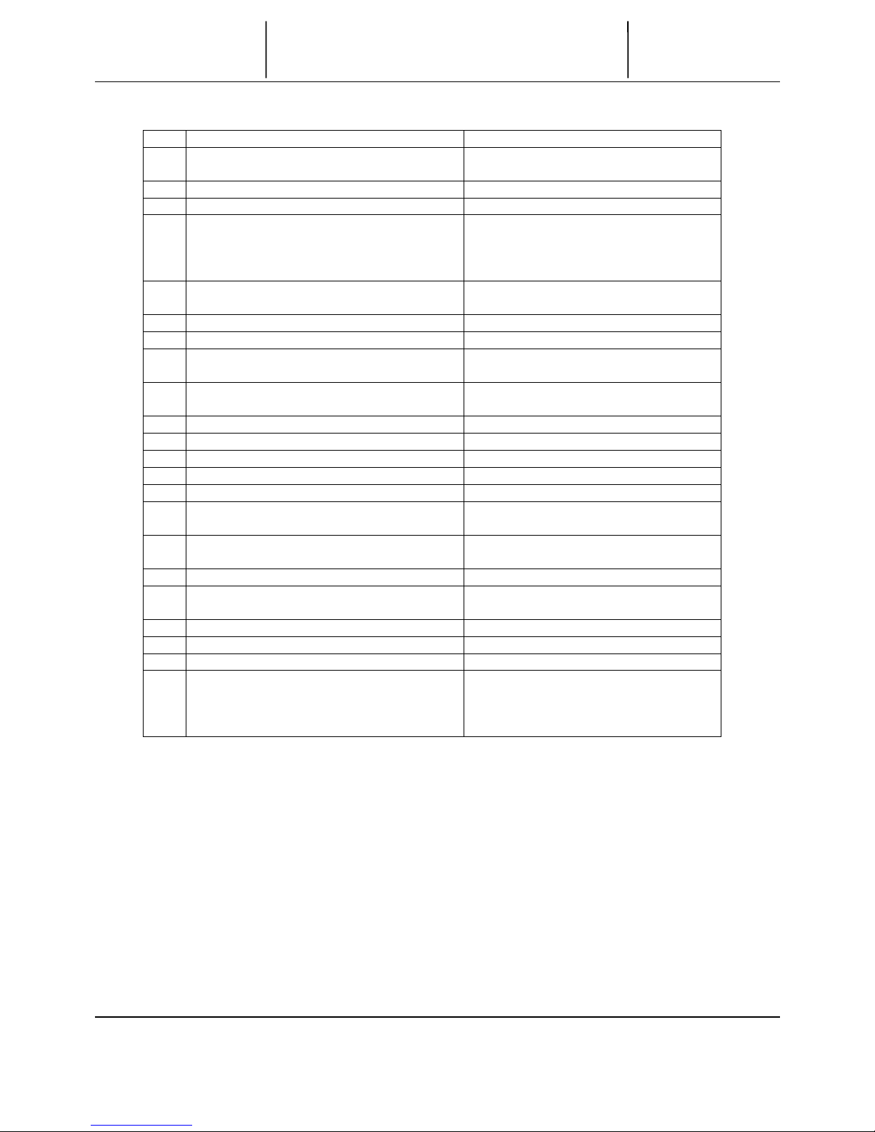
REVISION REFERENCE (G-L0022-01 G-L0022-02)
NEW PAGE PAGE TITLE REVISED ITEMS
1-2 LVT300-Vertical CNC Lathe 1. Addition: Note
1-4 Spec. Comparison Between
Dynamic Turn LVT300/300M and ist Competitors
1. Revision: Table
2-2 Machine Specifications 1. Revision: Swing over cross-slide
(∅280 to ∅320)
2. Revision: Z-axis travel (310 to
360mm)
3. Revision: ID tool shank dia. indexing
time (0.1 to 0.15 sec)
4. Revision: Weight (5,500 to 6,000kg)
3-2 Kit Specifications 1. Revision: Table
4-1-1 Layout-Chip Side Disposal 1. Addition: New Page
9-2 Servo System Mechanism 1. Revision: Drawing
11-1 Table of Machine Constants 2. Revision: Start up time
12-1 Machining Capacity and
Accuracy
1. Addition: New Page
13-1 Machine Operation Time
Tab le
1 Revision: Feed axis starting time
2. Revision: Turret index time
14-1 Working Range Diagram 1. Revision: Drawing
14-2 Working Range Diagram 1. Revision: Drawing
14-3 Working Range Diagram 1. Revision: Drawing
14-4/14-5 Notes for Work Length
Range
1. Addition: New Pages
21-1-2 LVT300 System Layout
Example
1. Revision: Note
21-2-2 Work Changing Time Chart 1. Revision: Time Chart
21-3 – 21-9 2. Elimination: Pages
REVISION REFERENCE (G-L0022-02 G-L0022-03)
NEW PAGE PAGE TITLE REVISED ITEMS
4-2 Foundation Plan 1. Revision: Drawing
000-2 LT9910T.doc
No. Item Content
1 Technical Information for Sales Promotion - Features
- Spec Comparison with Competitors
2 Machine Specifications - Specification Table
3 Specifications - Specifications for Machine
4 Dimensional Drawings - Dimensional Drawings (Standard)
- Chip Side Disposal
- Foundation Plan
- CE *
5 Spindle Dimensions - Standard Spindle
- Spindle Rear End Dimensions
6 Bed Dimensions
7 Turret Dimensions - V12VDI Turret
8 Spindle Power/Torque Transmission
Diagram
- Standard Spindle
9 Mechanical Drawings - Turret
- Servo System Mechanism
10 Hydraulic Circuit Diagram
11 Machine Constants Table
12 Machining Capacity/Accuracy *
13 Operation Time Table *
14 Working Range Diagrams
15 Tooling (VDI) - Tooling System
- Tool Interference Diagram
16 Hydraulic Chuck Installation Drawing - Chuck Installation Drawing
17 Touch Setter *
18 Lubrication Chart - Lubrication list
- Oil Specifications
19 Chip Conveyor *
21 System Layout Example
22 Power Requirements
The final drawings or optional
specifications indicated with * will be
delivered later, because they are
under preparation.
Any technical information is subject to change without notice.
OKUMA Corporation
TTTTechnical SSSSheet
TABLE OF CONTENTS
TABLE OF CONTENTSTABLE OF CONTENTS
TABLE OF CONTENTS
INFORMATION NO.
2059-LVT300
P-(i)
* Vertical CNC lathe equipped with the spindle loading function provides
flexibility in your line construction.
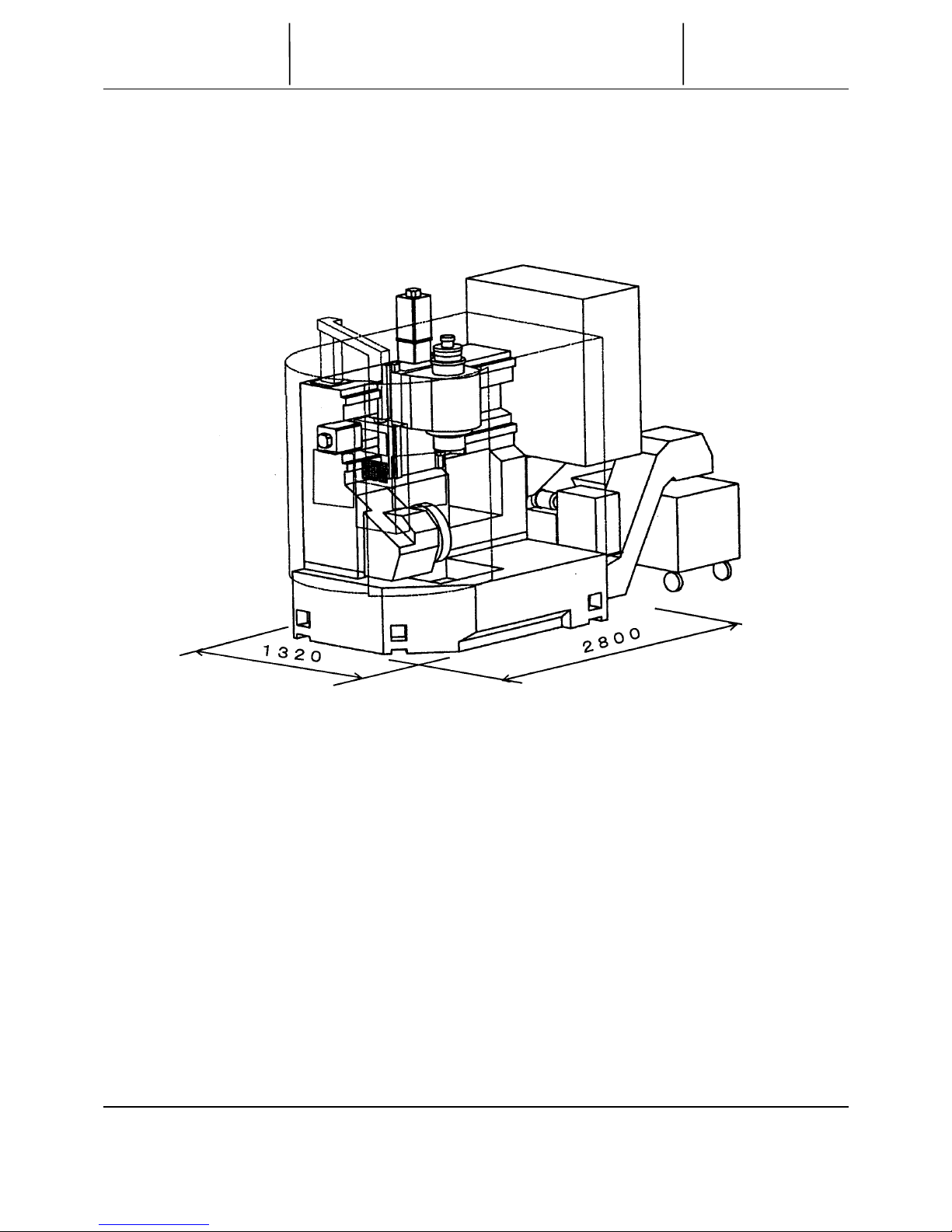
* Having a smaller machine width, this next-generation machine ensures
easy workpiece change.
●Applicable to line construction
* Vertical spindle capable of loading workpieces
* Minimum machine width:
Only 1.3 m though the machine is equipped with an 8-inch chuck.
●High productivity
* High feedrate by linear guides employed for all the feed axes Rapid feedrate:
X: 60 m/min (197 fpm), Z: 30 m/min (98 fpm)
* High-speed integral motor/spindle:
4,000 min
-1
, 22/15 kW (30/20 hp)
* V12 NC turret indexed at high speed: 0.15 sec/stat.
●High accuracy
* Thermally stabilized bed with box construction
* Coolant and chip discharged directly under the machine
* Gearless headstock and high-precision servo
* Thermal deviation compensation function
●Minimum cost
* Loading system not needed
TTTTechnical SSSSheet
LVT 300
LVT 300LVT 300
LVT 300
VERTICAL CNC LATHE
VERTICAL CNC LATHEVERTICAL CNC LATHE
VERTICAL CNC LATHE
INFORMATION NO.
2059-LVT300
1-2
Any technical information is subject to change without notice.
OKUMA Corporation
(51.97)
(110.24)

SPEC COMPARISON BETWEEN DYNAMIC TURN LVT300/300-M AND ITS COMPETITORS
Manufacturer OKUMA HITACHI SEIKI EMAG INDEX
Model LVT300 LVT300-M CS20 VSC200 VSC250 V200
Outside view
Standard chuck 8” ∅210 (8.27) (8”) ∅200 (7.87) ∅200/250 (7.87/9.84) ∅200 (7.87)
Swing over saddle mm (in.) ∅320 (12.6) (Limited by Z-axis cover) ∅400 (15.75)
Max. turning dia. mm (in.) ∅280 (11.02) ∅400 (15.75) ∅ 200 ∅200 ∅420 × 180 (16.54 )
Max. workpiece length mm (in.) 200 (11.02 × 7.87) 0 (15.75 × 5.91) 180 200 180 (7.09)
Capacity
Max. loading capacity kg (lb) 20 (44) 20 (44)
X-axis mm (in.) 210 (8.27) (machining travel) +
845 (33.27) (loading/unloading travel)
190 (7.48) (machining travel)
+1,120 (44.09)
(loading/unloading travel)
550 (21.65) 685 (26.97) 520 (20.47)
Z-axis mm (in.) 360 370 (14.57) 200 (7.87) 200 (7.87) 200 (7.87)
Travels
Work changing time sec 5.5 15 5 to 7 5 to 7
Spindle speed min
-1
4,000 5,000 6,500 6,000 5,000 (7,500)
Speed range (2 auto ranges) First gear
Spindle nose JIS A2-6 JIS A2-6 DIN55026 A5 DIN55026 A6 ISO 702/1 type 5(4)
Front bearing dia. ∅100 (3.94) ∅100 (3.94) ∅100 (3.94) ∅100 (3.94) ∅100 (∅75) {3.94 (2.95)}
Spindle bore mm (in.) ∅62 (2.44) ∅59 (2.32)
Spindle drive motor Output: kW (hp) Built-in motor: VAC 22/15 (20 min: cont.) AC11/7.5 AC34 AC39 Built-in motor: 29/20 (21/13)
Torque: Nm (lbf-ft) 412 208 153 460 140
Type V12VDI NC non-lift turret
V12 multi-function NC non-lift turret
12-angle base holder V12 V12 14
No. of tools 12 12 (for L and M) 12 12 12 14
Tool shank height/boring bar shank dia.
o25/∅40 (VDI holder shank dia.) ∅40) o25/∅32 ∅40 (DIN69880) ∅40 (DIN69880) o25
Turret
Indexing time sec 0.15 (1 index) 0.2 (1 index)
Spindle speed min
-1
-
4,500 3,000 6,000
Rotary tool
spindle
Rotary tool spindle drive motor kW (hp)
-
5.5/3.3 (7.5/4.4) 3.7 (5) 12.5 (16.67) 9.5 (12.67)
X-axis mm/min (fpm) 60 (2.36) 30 (1.18) 60 (2.36) 45 (1.77) 30 (1.18)Feedrate
Z-axis mm/min (fpm) 30 (1.18) 30 (1.18) 30 (1.18) 30 (1.18) 30 (1.18)
Motor Coolant pump kW (hp) 0.25 (0.333) 1.1 (1.5)
Height mm (in.) 2,500 (98.43) 2,743 (107.99) 2,800 (110.24) 2,650 (104.33)
Floor space mm × mm
(in. × in.)
1,320 × 2800
(51.97 × 110.06)
2,838 × 2,587
(111.73 × 101.85)
1,350 × 2,890
(53.15 × 113.78)
1,350 × 3,100
(53.15 × 122.05)
2,080 × 1,900
(81.89 × 74.80)
Machin e
size
Weight kg (lb) 5,500 (12,100) 6,000 (13,200) 5,000 (11,000) 6,500 (14,300) 6,500 (14,300)
Remarks
Indications in ( ) are for optional specifications.
Any technical information is subject to change without notice.
OKUMA Corporation
TTT
T
echnical
SSS
S
heet
SPEC COMPARISON BETWEEN DYNAMIC TURN
SPEC COMPARISON BETWEEN DYNAMIC TURN
SPEC COMPARISON BETWEEN DYNAMIC TURN
SPEC COMPARISON BETWEEN DYNAMIC TURN
LVT300/300-M AND ITS COMPETITORS
LVT300/300-M AND ITS COMPETITORS
LVT300/300-M AND ITS COMPETITORS
LVT300/300-M AND ITS COMPETITORS
INFORMATION NO.
2059-LVT300
1-4

002-2 LT9910E.doc
Model
LVT300
Swing over cross-slide
mm (in.)
∅320 (12.60)
Max. turning dia.
mm (in.)
∅280 (11.02)
Max. turning length
mm (in.)
200 (7.87)
Capacity
Recommended work weight
kg (lb)
20 (44)
*
X-axis
mm (in.)
210 (8.27) (for machining) + 845 (33.27) (for loading/unloading)
Z-axis
mm (in.)
360 (330 up to #0074)
Travels
Spindle speed
min
-1
40 to 4,000, [60 to 6,000]
Speed range Auto 2 ranges
Spindle nose JIS A2-6
Spindle bore
mm (in.)
∅62 (2.44)
Spindle
Front bearing ID
mm (in.)
∅100 (3.94)
Type V12 VDI NC non-lift
No. of tools 12
OD tool shank
mm (in.)
o25 × 25 (0.98 × 0.98) (VDI toolholder shank dia.: 40
(1.57))
ID tool shank dia.
mm (in.)
∅40 (1.57) (VDI toolholder shank dia.: ∅40 (1.57))
Turret
ID tool shank dia.
sec
0.15 Indexing time (per station)
Rapid traverse m/min (fpm) X: 60 (197), Z: 30 (98)
Spindle drive
kW (hp)
VAC22/15 (30/20) (20 min/cont.) [37/25 (50/33.3)]
Axis drive
kW (hp)
X-axis: 4, Z-axis: 6
Motors
Coolant pump
kW (hp)
0.25 (0.333)
Height
mm (in.)
2,500 (98.43)
Required floor space
mm × mm
(in. × in.)
1,320 × 3,200
(51.97 × 125.98) (Control panel included)
Machine
Specs
Weight
kg (lb)
5,500 (12,100)
NC
OSP-U100L
Values in [ ] are for high-speed and power-up specifications (optional).
*The max. load of the head stock is 70kg
(= Chuck + Cylinder + Draw Bar + Jaws •••• washers + workpiece)
OKUMA
OKUMA OKUMA
OKUMA Corporation
TTTTechnical SSSSheet
MACHINE SPECIFICATIONS
MACHINE SPECIFICATIONSMACHINE SPECIFICATIONS
MACHINE SPECIFICATIONS
INFORMATION NO.
2059-LVT300
2-2

003-2 LT9910.doc
SPECIFICATION FOR LVT300 CNC LATHE
o Estimated Spec
o Delivery Spec
Date
・ ・
Company
name
NC OSP-U100L
Standard specifications
T
Model
∅280 (110.24)
×
200 (7.87)
8-inch solid chuck
(N-08A601A)
with standard soft jaws (1 set)
Solid hydraulic cylinder
Spindle motor
VAC 22/15 kW (30/20 hp)
(20 min/cont.)
¡
Chucking
(RNKP120-25)
A
Spindle speed
40 to 4000 min
-1
¡ OD toolholder
C
Turret
V12 NC turret (VDI)
¡ ID toolholder base
H40
Hydraulic unit
¡
10-H40
Coolant supply system
¡
12-H40
Chip shield
¡
16-H40
Chip pan (rear discharge)
¡
20-H40
Standard
e
q
ui
p
ment
Work lamp (fluorescent)
¡
25-H40
Boring bar sleeve
32-H40
MT.No.1
MT.No.2
Machine-related equipment
Standard
accessories
Foundation washers
Leveling jack screws
Machine lifting hooks
Hand tools
¡
Drill sleeve
MT.No.3
NC OSP-U100L ¡
Tooling
Plug tool
Optional specifications Qty Optional accessories
Qty
Specifications for high speed/power-up spindle (A2-6)
Speed range to 6,000 min
-1
[37/25 kW (50/33.3 hp)]
Chip conveyor o Side disposal o Rear disposal
o L-type o H-type o Special
Chip bucket o L-type o H-type
o Special
TTTTechnical SSSSheet
SPECIFICATIONS
SPECIFICATIONSSPECIFICATIONS
SPECIFICATIONS
INFORMATION NO.
2059-LVT300
3-2
Any technical information is subject to change without notice.
OKUMA Corporation

OSP-U100L CNC Standard Specifications
Axis Control X,Z simultaneous 2-axis turning, simultaneous 3-axis multi-processing
Position feedback Full-range absolute positioning (zero point return is not required)
Tape format N4, G2, X+53, Z+53, I+53, K+53, F+53, S4, T4, M2
Reader/puncher interface RS-232C
Floppy disk input/output
3.5” floppy disk drive (internal), input and output a program via OSP formatted floppy disk
auto ISO/EIA code recognition; absolute, incremental or both
Programming Auto ISO/EIA code recognition: absolute, Incremental or both
Min command units X-axis: 1 µm (0.00004 in) [dia], Z-axis: 1 µm (0.00004 in)
Max command units 8-digit decimal, ±99999.999 mm(±3937 in)
Programmable units 1 µm (0.00004 in), 10 µm (0.00004 in), 1mm (0.04 in) [freely selectable]
Decimal point data 1 µm (0.00004 in), 10 µm (0.00004 in), 1mm (0.04 in) increments
Feed Feedrates are listed in the machine space, override: 0~200%, dwell: 0.01~99999.99 sec
Tooling Tool selection: 12 sets, tool offset (compensation): 32 sets, max compensation value:
±99999.999 mm (±3937 in)
Auto tool compensation: calculated from manually input wear and tear measurement values
Spindle VAC motor operation Direct spindle speed commands (S4), fixed cutting speed
Spindle speed override (50~200%), optimum turning speed designation
M-spindle motor operation (multimachining)
Direct input of the motor speed
Display NOTE 1) Color display panel, six LED for display of operation conditions
Manual operation
Spindle (inching: clockwise or counter-clockwise turning), tool rotation, pulse handle,
X-Z-axis manual feed
Multitasking Program writing, editing during work
Self-diagnostics
Automatic diagnostics and display of program, operation, machine, and NC system
Problems
Door interlock Safety function to interlock machine movement when door is opened or closed
NC torque limiter Instant detection of machine collision to reduce machine damage
Hi-G Control Calculation of the speed-control and torque properties of a motor for high-speed, high
stability positioning
Features
Other Buffer resister, zero offset, tool interference, software limit, chuck barrier, tailstock barrier,
droop control, single block, machine lock, block delete, optional stop, dry-run, stroke
end-limit cancel, etc.
Program selection 1 program from the registered list of programs
Sequence number search Advance to an appointed sequence number in a selected program
Sequence restart Restart from an Interrupted sequence
Manual interrupt/auto return Manual operation during automatic operation: return to interrupt point
Threading slide hold Slide hold during threading (optional for [G34/G35] non-fixed cycles)
Programming Editing, tape read verify, listing, etc. via the screen editor
Memory operation Tape less operation: Tape storage capacity: 160m (525 ft), max program length: 320m
(1050 ft)
Useful Help Alarm help, display of G, M-code contents
Useful PLC Display of PLC ladder drawings and PLC data
Operation
Data management
Output of tool offset, zero offset, measurement data to tape or floppy disk (tape readers
and punchers are optional)
Nose R compensation (2B) Automatic compensation for nose R dimension errors Including arbitrary shapes and arcs
Arc radius designation Circular interpolation by ordering the radius L and end points X, and Z
Arbitrary angle chamfering Simple programming of arbitrary angle chamfers (C, R)
Taper angle designation Taper interpolation by designating either the X-, or Z-axis and the starting point angle
mm/min (ipm)Programming Both mm/rev (ipr) and mm/min (ipm) feedrate units usable
Schedule program Non-stop operation possible by setting the sequence order of several work programs
Zero offsets via G-codes Program zero point offsets are possible
Threading Thread feed: 0.001~1000.000mm(0.00004~39.37in): possible to set the threading lead pitch
Chamfering ON/OFF, fixed cycle threading, non-fixed threading cycle
(the thread lead indicates the CNC limit value, the max thread lead differs per machine
specification)
Custom fixed cycle Threading cycle, grooving cycle, drilling cycle
User task 1 GOTO, IF statements, arithmetic, common variable, local variable
(system operation variables)
Programming Function
Control In/Out Comments can be added into programs
Note 1: The display screen varies with machine model. LU series, LT15, LT25 … 14” color CRT
Other models controlled by OSPU100L… 10.4” color TFT
Any technical information is subject to change without notice.
OKUMA Corporation
TTTTechnical SSSSheet
CNC
CNCCNC
CNC STANDARD SPECIFICATIONS
STANDARD SPECIFICATIONSSTANDARD SPECIFICATIONS
STANDARD SPECIFICATIONS
INFORMATION NO.
2059-LVT300
3-4

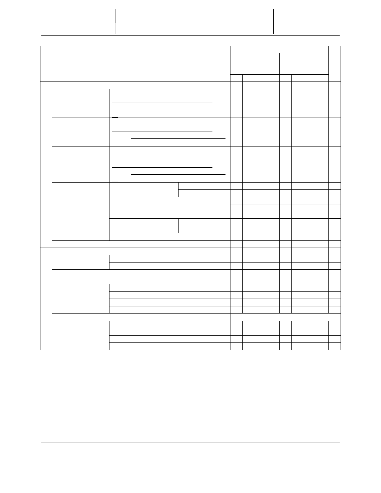
Specifications
NML ANM
Onetouch
IGF
Onetouch
IGF-M
OSP-U100L Optional specifications
EDEDEDED
Single
Auto programming function LAP4
●●●●●●●●
Arc threading
●●●●
Inch/metric switching
●●●●
User Task 2
Sub-programming, calculation, function
operations
●●●●●●●●
I/O variables: 8 variables each (incl. the
above functions)
64 sets
Tool offset function
(std. 32 sets)
96 sets
Common variables: 1000 (std. 200)
Threading phase matching (spindle orientation separately
selected)
Slide hold during thread cutting (G34, G35)
Multifunction lathe Coordinate conversion
▲▲▲▲ ●●
spec Contour generation
▲▲▲▲ ●●
Flat turning
Programming
One-touch IGF (incl. LAP4, animation)
●
One-touch IGF with IGF convert function
●
One-touch IGF multifunction spec
●
One-touch IGF multifunction spec with IGF convert function
●
IGF-L3 (incl. LAP4, animation)
IGF-L3 with IGF convert function
IGF-L3 multifunction spec
Interactive functions
IGF-L3 multifunction spec with IGF convert function
Program store capacity 640 m
●●●
Standard 320 m 1280 m
●●●●
2560 m
●
5120 m
10240 m
Operation buffer capacity 640 m
Standard 320 m 1280 m
Program capacity
Any technical information is subject to change without notice.
OKUMA Corporation
TTTTechnical SSSSheet
OPTIONAL SPECIFICATIONS
OPTIONAL SPECIFICATIONSOPTIONAL SPECIFICATIONS
OPTIONAL SPECIFICATIONS
INFORMATION NO.
2059-LVT300
3-6-1

Specifications
NML ANM
Onetouch
IGF
Onetouch
IGF-M
OSP-U100L Optional specifications
EDEDEDED
Single
Animated simulation (incl. cycle time calculation function)
●●●●●●
Cycle time over check
●●●●●●●●
Load monitor function (spindle, feed axis)
●●●●●●
Tool life management function
●●●●
Operation end buzzer
Chucking error detection Included in machine specifications
Work counter Counting only ( pc)
Cycle stop ( pc)
Start disabling ( pc)
Hourmeter Power ON time
Spindle rotating time
NC running time
NC operation monitor (incl. counter, integrating function)
●●●●●●●●
NC work counter (alarm stop at count-up)
Operation end lamp (yellow rotating beacon)
Alarm lamp (red rotating beacon)
Monitoring function
3-step status indicator lamp type A (type B)
●●●●●●●●
In-process work gauging Included in machine specifications
Z-axis auto zero offset by touch sensor
C-axis auto zero offset by touch sensor
Measurement data Standard channel
printout
RS232C
Additional channel
Printer ( )
Post-process work
Quantitative compensation system [5 steps,
7 steps]
gauging interface BDC system
CEJ MATIC (for export)
RS232C (incl. dedicated channel)
Touch setter gauging [M, A] Included in machine specifications
Size catcher A (without calipers)
B (with 150 mm calipers)
Gauging function
Any technical information is subject to change without notice.
OKUMA Corporation
TTTTechnical SSSSheet
OPTIONAL SPECIFICATIONS
OPTIONAL SPECIFICATIONSOPTIONAL SPECIFICATIONS
OPTIONAL SPECIFICATIONS
INFORMATION NO.
2059-LVT300
3-6-2
Specifications
NML ANM
Onetouch
IGF
Onetouch
IGF-M
OSP-U100L Optional specifications
EDEDEDED
Single
Additional RS232C channel (std. 1 channel)
RS232C
Maker
connection cable
Type
Printer
Maker
Type
Printer cable RS232C interface cable
Maker
Type
DNC-A
Standard channel
●●●●
Channel added
DNC-B (incl. dedicated channel)
DNC-C [C1, C2, C3] (incl. dedicated
channel)
DNC-[P1,P2,P3]
Standard channel
* Channel added
Connection with
DNC
(User is requested
to prepare cables
and connect the
system.)
DNC-[T1,T2,T3] *
External input/output, communication function
Spindle orientation (electrical control)
●●●●
Auto power shutoff M02, alarm
function
Warm-up function (Warm-up operation by calendar timer)
Tool retraction cycle
External program A (pushbutton) 8 kinds
select B (rotary switch) 8 kinds
C1 (digital switch) BCD2 digits
C2 (digital switch) BCD4 digits
Interface with Okuma loader (OGL) Included in loader specifications
Interface with other Type B (machine-mastered)
maker’s Type C (robot/loader-mastered)
robot/loader Type D
Automation, untended operation
Type E
Any technical information is subject to change without notice.
OKUMA Corporation
TTTTechnical SSSSheet
OPTIONAL SPECIFICATIONS
OPTIONAL SPECIFICATIONSOPTIONAL SPECIFICATIONS
OPTIONAL SPECIFICATIONS
INFORMATION NO.
2059-LVT300
3-6-3

Specifications
NML ANM
Onetouch
IGF
Onetouch
IGF-M
OSP-U100L Optional specifications
EDEDEDED
Single
Bar feeder Bar feeder unit Included in machine specifications
Interface only
Maker
Type
Cycle time Operation time reducing function
●●●●●●●●
reducing Chuck open/close during spindle rotation
function *
Tailstock auto advance/retract during spindle
rotation
Automation, untended operation
Position feedback by ABSO SCALE (XA, ZA, XB, ZB) *
1/10 µm control *
Pitch error compensation (XA, ZA, XB, ZB)
High speed, high
accu
r
acy
Thin-type monochromatic operation panel (not selectable for some
machine models)
Earth leakage breaker
External M code signal [2 sets, 4 sets, 8 sets ( )]
Others
Note 1: NML, ANM, E, and D are abbreviation of NORMAL, ANIMATION, ECONOMY, and DELUX.
Note 2: When selecting a kit specification, encircle E or D of the required kit. To add a function or specification to
the selected kit, put a circle in the corresponding kit column. W hen selecting a function or specification
without selecting a kit, put a circle in the corresponding “Single” column.
Note 3: Installation of the items indicated with * requires technical consultation including review of the machine
specifications.
Note 4: For the specifications given in [ ], select a required specification by encircling.
Note 5: The functions indicated with ▲ are provided only for the multifunction model.
Note 6: When you need the 3-step status indicator lamp type B, encircle “Type B”.
Any technical information is subject to change without notice.
OKUMA Corporation
TTTTechnical SSSSheet
OPTIONAL SPECIFICATIONS
OPTIONAL SPECIFICATIONSOPTIONAL SPECIFICATIONS
OPTIONAL SPECIFICATIONS
INFORMATION NO.
2059-LVT300
3-6-4

TTTTechnical SSSSheet
DIMENSIONAL DRAWINGS
DIMENSIONAL DRAWINGSDIMENSIONAL DRAWINGS
DIMENSIONAL DRAWINGS
(MACHINE WITH L-TYPE TURRET)
(MACHINE WITH L-TYPE TURRET)(MACHINE WITH L-TYPE TURRET)
(MACHINE WITH L-TYPE TURRET)
INFORMATION NO.
2059-LVT300
4-1
10-547-700-002
Any technical information is subject to change without notice.
OKUMA Corporation
Any technical information is subject to change without notice.
OKUMA Corporation
TTTTechnical SSSSheet
LAYOUT
LAYOUTLAYOUT
LAYOUT
CHIP SIDE DISPOSAL
CHIP SIDE DISPOSALCHIP SIDE DISPOSAL
CHIP SIDE DISPOSAL
INFORMATION NO.
2059-LVT300
4-1-1
10-547-700-028

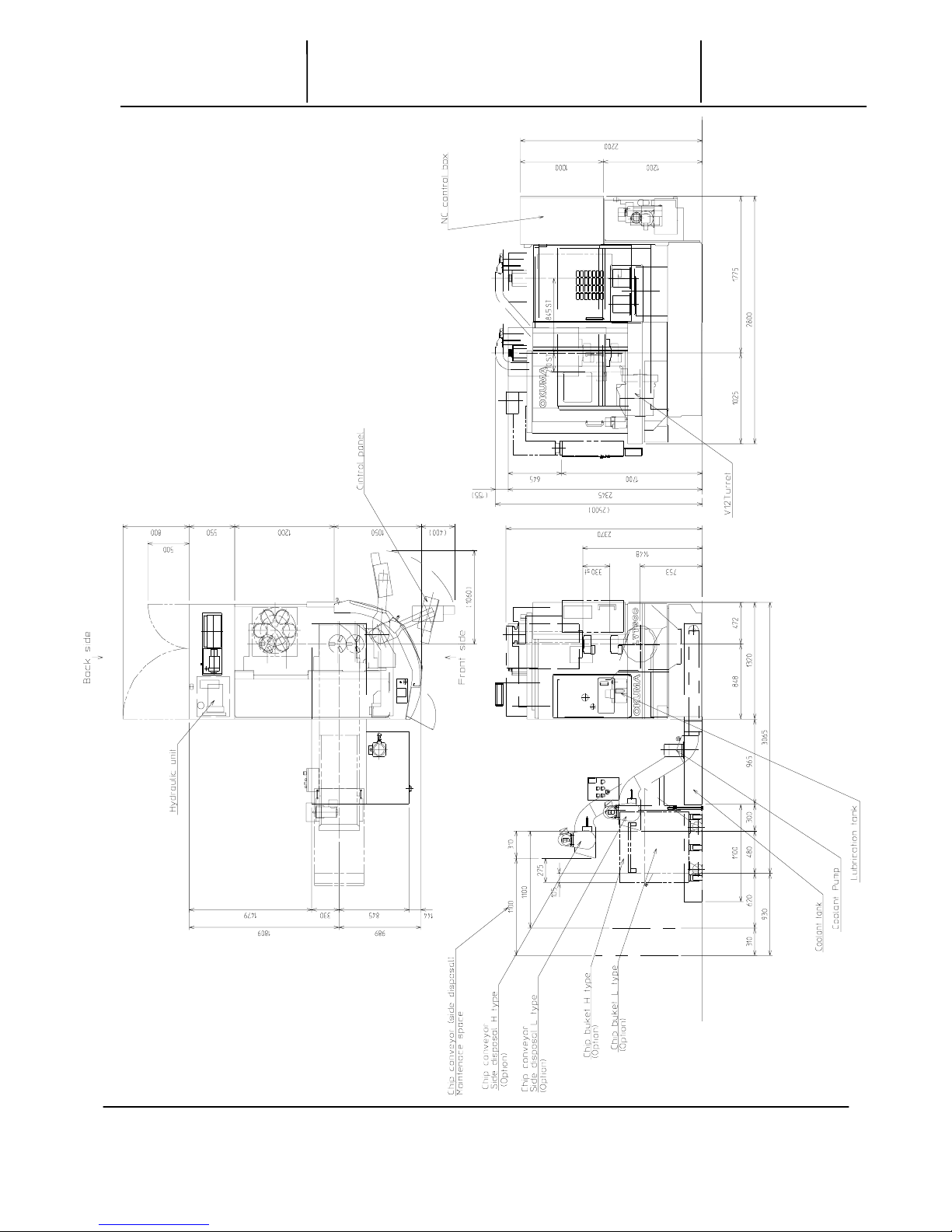
TTTTechnical SSSSheet
FOUNDATION PLAN
FOUNDATION PLANFOUNDATION PLAN
FOUNDATION PLAN
INFORMATION NO.
2059-LVT300
4-2
Any technical information is subject to change without notice.
OKUMA Corporation
13-547-720-001

005-1 LT9910q.doc
φ100主軸(標準主軸)
φ100 standard spindle
LB300、LU15と主軸は共通。(参考図 00-535.010.004-3,-011-3)
This spindle is also used in LB300 and LU15.
(Refer to the drawings in 00-535.010, 004-3 and -011-3.)
(
00-547-010-004
)
TTTTechnical SSSSheet
主主主主 軸軸軸軸 寸寸寸寸 法法法法 図図図図
SPINDLE DIMENSIONS
SPINDLE DIMENSIONSSPINDLE DIMENSIONS
SPINDLE DIMENSIONS
INFORMATION NO.
2059-LVT300
5-1
Any technical information is subject to change without notice.
OKUMA Corporation
 Loading...