


AM/FM
RADIO/CD PLAYER
INTERCOM SYSTEM
MODEL: IMA-4406 SERIES MASTER STATION
To register this product, visit www.nutone.com
INSTALLATION
INSTRUCTIONS
This booklet contains information for installing the master station. All system wiring and rough-in frames should be installed before mounting and wiring the master station.
Refer to the installation instructions packaged with the rough-in frames for detailed wiring information. For more detailed information on wiring and mounting other system components (i.e., speaker, remote control, etc.), refer to the installation instructions packaged with each separate component.
IMA-4406 SERIES REPRESENTATIVE WIRING ILLUSTRATION
PUSHBUTTON |
NUTONE CHIME |
|
14/2 WITH GROUND |
|
|
Use this diagram for reference only. |
||||||
TRANSFORMER |
|
|
|
|||||||||
|
|
|
|
|||||||||
|
120V 60HZ |
(OBSERVE LOCAL CODES) |
|
|
See IR-105 Rough-in frame instructions |
|||||||
|
|
|
|
|||||||||
|
|
(CLASS 1) |
120V 60HZ (CLASS 1) |
|
|
for detailed wiring. |
|
|||||
|
|
(OBSERVE |
|
|
|
|
|
|
|
|
|
|
|
|
LOCAL CODE) |
|
|
|
|
|
NUTONE |
|
|
|
|
|
S-143) |
|
|
|
|
|
|
OUTSIDE |
|
|
||
|
|
|
|
|
|
|
IW-6 |
|
IW-2 |
OUTSIDE |
||
|
|
|
|
(2) 801T |
|
|
REMOTE |
|||||
|
PUSHBUTTON FOR |
|
|
|
|
|
|
SPEAKER |
||||
|
|
|
|
|
|
CONTROL |
|
|||||
|
(NUTONE |
OPTIONAL CHIME |
|
TRANSFORMERS |
|
|
|
|
||||
|
|
|
|
|
|
|
||||||
|
MODULE |
|
SECONDARY: |
|
|
|
|
|
|
|||
|
|
|
|
|
|
|
|
|
||||
|
|
|
|
|
18V, 72VA |
|
|
|
|
|
|
|
|
18/2 |
INSIDE |
|
|
|
|
|
|
INSIDE |
IW-2 |
INSIDE |
|
|
ANTENNA |
|
|
|
|
|
|
REMOTE |
|
|||
|
|
|
|
|
|
|
|
SPEAKER |
||||
|
|
|
|
|
|
EARTH |
|
|
CONTROL |
|
||
|
|
|
|
|
|
|
|
|
|
|||
OPTIONAL |
ATTIC |
|
|
|
GROUND |
|
IW-6 |
|
|
|
||
|
|
|
|
|
|
|
|
|
|
|||
ELECTRONIC |
|
|
|
|
|
|
|
|
|
|
||
|
|
|
|
|
|
|
NUTONE |
|
|
SPEAKERS |
||
DOOR CHIME |
|
|
|
|
|
|
|
|
|
|||
|
|
|
|
|
|
|
|
|
|
INSIDE |
||
|
|
300´ MAX |
|
|
|
|
14 GA |
|
|
|
|
|
|
|
|
|
|
|
|
|
|
|
|
|
|
200´ MAX |
NUTONE IW-2 |
|
|
|
|
|
|
IW-6 |
|
W/CONTROLS |
||
|
|
|
|
|
|
|
|
|
||||
NUTONE |
|
|
|
|
|
|
|
|
|
|
|
|
IW-2 |
|
|
|
|
|
|
|
|
|
|
|
|
|
|
|
|
|
|
|
|
|
|
TRANSFORMER |
|
|
|
|
|
|
|
|
|
|
|
|
|
|
120V 60HZ |
|
|
|
|
IMA-4406 |
|
|
|
301T |
(CLASS 1) |
|||
|
|
|
|
|
|
|
|
(OBSERVE |
||||
|
|
|
MASTER STATION |
100´ MAX S-143 |
|
LOCAL CODE) |
||||||
14 GA |
|
|
|
|
||||||||
|
|
|
|
|
|
|
|
|
|
|
|
|
GROUND |
|
|
|
|
|
|
100´ MAX S-143 |
|
|
|||
|
|
|
|
|
|
|
|
|
|
|||
|
|
IW-2 |
|
|
|
|
|
|
|
OPTIONAL WIRING |
|
|
|
|
|
|
|
|
|
|
|
|
|
||
|
|
|
|
|
|
NUTONE |
|
|
|
FOR DOOR |
DR-1/DR-2 |
|
CABLES |
VOLUME |
NUTONE 2-IW |
|
|
6-IW |
|
|
RELEASE |
||||
|
|
|
|
DOOR RELEASE |
||||||||
|
|
|
|
|
|
|
|
|
|
|||
SHIELDED |
MUSIC |
|
|
|
|
|
|
|
|
|
||
|
|
|
|
|
|
|
|
|
|
|||
AUDIO |
|
DISTRIBUTION |
|
|
|
|
|
|
|
|
|
|
|
|
CONTROL |
|
|
|
|
|
|
IA-6C |
|
|
DESKTOP |
|
|
|
|
|
|
|
|
|
|
|
||
|
OPTIONAL |
IW-2 |
|
|
|
|
5˝ PATIO |
|
RECEPTACLE |
|
||
|
DOOR |
|
|
|
|
FRAME WITH 5˝ |
||||||
|
MUSIC |
|
|
|
|
|
|
|||||
|
|
SPEAKER |
|
|
|
|
REMOTE |
|||||
|
SOURCE |
|
SPEAKER |
|
|
|
IA-6 |
|||||
|
|
W/CONTROLS |
|
|
|
|||||||
|
|
|
|
|
|
|
|
|||||
|
|
|
|
|
|
|
|
PLUG |
|
|||
|
|
|
|
|
|
|
|
|
|
|
|
|
|
|
|
MUSIC |
|
|
|
|
|
|
|
|
|
|
|
|
|
|||||
|
|
|
DISTRIBUTION |
|
|
|
|
DOOR SPEAKER MODELS WITH CHIME |
||
|
|
|
SPEAKER |
|
|
|
|
|||
|
|
|
|
|
|
|
PUSHBUTTON ALSO REQUIRE 18/2 (S-143) |
|||
|
|
|
|
|
|
|
|
|
|
|
120V. 60HZ (CLASS 1) |
|
|
300´ MAX |
TO CHIME LOCATION OR IW-2 TO MASTER |
||||||
(OBSERVE LOCAL CODE) |
|
|
IF CHIME MODULE IS USED. |
|||||||
|
|
|
|
|||||||

INSTALLATION |
|
TABLE OF CONTENTS |
|
INSTALLATION |
PAGE |
Contents of Carton . . . . . . . . . . . . . . . . . . . . . . . . . . . . . . . . . . . . . . . . . . . . . . . . . . . . . . . . . . . . . . . . . . . . . . . |
. . . . . .3 |
Precautions and Guidelines . . . . . . . . . . . . . . . . . . . . . . . . . . . . . . . . . . . . . . . . . . . . . . . . . . . . . . . . . . . . . . . . . |
. . . . .3 |
Wiring Specifications . . . . . . . . . . . . . . . . . . . . . . . . . . . . . . . . . . . . . . . . . . . . . . . . . . . . . . . . . . . . . . . . . . . . . . |
. . . . .3 |
Remote Station Wiring . . . . . . . . . . . . . . . . . . . . . . . . . . . . . . . . . . . . . . . . . . . . . . . . . . . . . . . . . . . . . . . . . . . . . |
. . . . .3 |
Maximum Number of Remote Stations . . . . . . . . . . . . . . . . . . . . . . . . . . . . . . . . . . . . . . . . . . . . . . . . . . . . . . . . . |
. . . . .3 |
Mounting the Terminal Board . . . . . . . . . . . . . . . . . . . . . . . . . . . . . . . . . . . . . . . . . . . . . . . . . . . . . . . . . . . . . . . . |
. . . . .4 |
Connecting the Remote Wiring . . . . . . . . . . . . . . . . . . . . . . . . . . . . . . . . . . . . . . . . . . . . . . . . . . . . . . . . . . . . . . . |
. . . . .4 |
Connecting Volume Control Wiring . . . . . . . . . . . . . . . . . . . . . . . . . . . . . . . . . . . . . . . . . . . . . . . . . . . . . . . . . . . |
. . . . .5 |
Connecting Door Speaker Wiring . . . . . . . . . . . . . . . . . . . . . . . . . . . . . . . . . . . . . . . . . . . . . . . . . . . . . . . . . . . . . |
. . . . .5 |
Preparing Master Station Panel for Optional Door Release Pushbutton . . . . . . . . . . . . . . . . . . . . . . . . . . . . . . . |
. . . . .5 |
Mounting the Optional Chime Module in the Master Station Panel . . . . . . . . . . . . . . . . . . . . . . . . . . . . . . . . . . . |
. . .5, 6 |
Mounting the Master Station . . . . . . . . . . . . . . . . . . . . . . . . . . . . . . . . . . . . . . . . . . . . . . . . . . . . . . . . . . . . . . . . . |
. . . . .6 |
Connecting the Power Transformers . . . . . . . . . . . . . . . . . . . . . . . . . . . . . . . . . . . . . . . . . . . . . . . . . . . . . . . . . . |
. . . . .7 |
Mounting the Transformer Cover . . . . . . . . . . . . . . . . . . . . . . . . . . . . . . . . . . . . . . . . . . . . . . . . . . . . . . . . . . . . . |
. . . . .7 |
Connecting the Master Station to the Terminal Board . . . . . . . . . . . . . . . . . . . . . . . . . . . . . . . . . . . . . . . . . . . . . |
. . . . .8 |
Connecting the Radio Antenna . . . . . . . . . . . . . . . . . . . . . . . . . . . . . . . . . . . . . . . . . . . . . . . . . . . . . . . . . . . . . . . |
. . . . .9 |
Connecting the Optional Chime Module . . . . . . . . . . . . . . . . . . . . . . . . . . . . . . . . . . . . . . . . . . . . . . . . . . . . . . . . |
. . . . .9 |
Connecting Optional Electronic Chime . . . . . . . . . . . . . . . . . . . . . . . . . . . . . . . . . . . . . . . . . . . . . . . . . . . . . . . . . |
. . . . .9 |
Connecting Optional Accessories . . . . . . . . . . . . . . . . . . . . . . . . . . . . . . . . . . . . . . . . . . . . . . . . . . . . . . . . . . . . . |
. . . .10 |
Connecting Power to the Optional CP-95 Cassette Player . . . . . . . . . . . . . . . . . . . . . . . . . . . . . . . . . . . . . . . . . |
. . . .10 |
Mounting and Connecting Optional Door Release Pushbutton . . . . . . . . . . . . . . . . . . . . . . . . . . . . . . . . . . . . . . |
. . . .11 |
Connecting the Memory Back Up Battery . . . . . . . . . . . . . . . . . . . . . . . . . . . . . . . . . . . . . . . . . . . . . . . . . . . . . . |
. . . .11 |
Securing the Master Panel . . . . . . . . . . . . . . . . . . . . . . . . . . . . . . . . . . . . . . . . . . . . . . . . . . . . . . . . . . . . . . . . . . |
. . . .11 |
Powering Up the System . . . . . . . . . . . . . . . . . . . . . . . . . . . . . . . . . . . . . . . . . . . . . . . . . . . . . . . . . . . . . . . . . . . |
. . . .11 |
OPERATIONAL CHECKOUT
System Operating Controls . . . . . . . . . . . . . . . . . . . . . . . . . . . . . . . . . . . . . . . . . . . . . . . . . . . . . . . . . . . . . . . . . . . . .12
Digital Clock . . . . . . . . . . . . . . . . . . . . . . . . . . . . . . . . . . . . . . . . . . . . . . . . . . . . . . . . . . . . . . . . . . . . . . . . . . . . . . . . .13
System Checkout . . . . . . . . . . . . . . . . . . . . . . . . . . . . . . . . . . . . . . . . . . . . . . . . . . . . . . . . . . . . . . . . . . . . . . . . . . . . .13
Setting Program Audio Controls . . . . . . . . . . . . . . . . . . . . . . . . . . . . . . . . . . . . . . . . . . . . . . . . . . . . . . . . . . . . . . .13, 14
Setting Intercom Volume . . . . . . . . . . . . . . . . . . . . . . . . . . . . . . . . . . . . . . . . . . . . . . . . . . . . . . . . . . . . . . . . . . . . . . .14
Setting Internal Intercom Volume Control . . . . . . . . . . . . . . . . . . . . . . . . . . . . . . . . . . . . . . . . . . . . . . . . . . . . . . . . . . .14
Setting the BEEP Tone Level . . . . . . . . . . . . . . . . . . . . . . . . . . . . . . . . . . . . . . . . . . . . . . . . . . . . . . . . . . . . . . . . . . . .14
Setting the External Audio Source Level . . . . . . . . . . . . . . . . . . . . . . . . . . . . . . . . . . . . . . . . . . . . . . . . . . . . . . . . . . .14
Diagnostic Tests . . . . . . . . . . . . . . . . . . . . . . . . . . . . . . . . . . . . . . . . . . . . . . . . . . . . . . . . . . . . . . . . . . . . . . . . . . . . . .15
Resetting the Microprocessor . . . . . . . . . . . . . . . . . . . . . . . . . . . . . . . . . . . . . . . . . . . . . . . . . . . . . . . . . . . . . . . . . . . .15
INSTALLER’S TROUBLESHOOTNG GUIDE . . . . . . . . . . . . . . . . . . . . . . . . . . . . . . . . . . . . . . . . . . . . . .16, 17, 18
WARRANTY . . . . . . . . . . . . . . . . . . . . . . . . . . . . . . . . . . . . . . . . . . . . . . . . . . . . . . . . . . . . . . . . . . . . . . . . . . . . . . . . . . .20
2

INSTALLATION
CONTENTS OF CARTON
Check ( ) for the following IMA-4406 carton contents.
IMA-4406 master station
Terminal board
Transformer cover
Hardware bag assembly containing: 2 - shoulder screws
12 - No. 6 x 3/8 screws
4 - colored panel mounting screws
4 - ‘L’ panel mounting brackets
Homeowner’s manual with room labels
Installation instructions
Product Registration Warranty Card
NOTE TO INSTALLER: Do not discard these installation instructions. Please transfer all installation instructions, warranty registration and homeowner’s manual to the homeowner.
PRECAUTIONS AND GUIDELINES
The NuTone IMA-4406 master station has been designed for ease of installation. Please read and follow ALL installation instructions, guidelines and precautions. Any deviation from these instructions or miswiring combinations may result in unit failure and void of warranty.
WARNING!
120 Volt AC Power to Transformers in the IR-105 Rough-in MUST Remain OFF until ALL System Wiring at the Master and Remote Stations is Complete.
•Observe all local building regulatory codes in your area.
•All screw terminals at the master and remote stations must be secure.
•Observe all color code connections of wires when connecting the remote stations to the master.
•The IMA-4406 is designed to be installed with only NuTone specified wire. No other wire should be used. The use of wire other than NuTone wire will void all NuTone warranties and may result in faulty installation and improper operation.
IMPORTANT WARNING!
THE POWER TRANSFORMER CONTAINS AN INTERNAL FUSE.
DO NOT SHORT THE LOW VOLTAGE CONNECTING SCREWS OF THE TRANSFORMER OR THE TRANSFORMER WILL BE DESTROYED!
WIRING SPECIFICATIONS
See the IR-105 master rough-in frame installation instructions for detailed wiring information.
Use NuTone IW-6, 3 twisted pair for connecting:
•Remote controls to master
•Remote stations to master
Use NuTone IW-2, 22 ga. twisted pair for connecting:
•Door speakers to master
•Remote controls to speakers
•Speaker volume control (IC901) to master
•Speaker volume control (IC901) to speakers
•Electronic chime audio output to master
•Pushbutton to chime module
Use NuTone S-143, 18 ga. twisted pair for connecting:
•Pushbutton to electronic chime
•Electronic chime to chime transformer
Use Nº14/2 power cable with ground, Class 1 UL Listed (Observe local codes) for connecting:
• Transformers to 120v AC
Use shielded audio cable for connecting external audio sources to the master station.
REMOTE STATION WIRING
An individual 6-wire cable (IW-6) must be connected from each remote station or remote control location to the master station’s terminal board.
Maximum station wire length: 750 ft.
IMPORTANT! NuTone cannot be responsible for improper system operation that results from interference generated by light dimmers, fluorescent lighting fixtures, and similar electrical products. Such interference must be corrected at the source. TO HELP REDUCE THIS INTERFERENCE, ALL WIRING CONNECTIONS TO THE MASTER MUST BE PLACED AT LEAST 12 INCHES FROM ANY AC POWER WIRING. AVOID RUNNING INTERCOM WIRES PARALLEL TO AC POWER WIRING.
Maximum total length of IW-6 cable per system: 4,000 ft.
MAXIMUM NUMBER OF REMOTE STATIONS
The master station will accommodate up to 9 connections at the terminal board. These connections can be any combination of remote stations, remote controls or volume
NOTE: NEVER connect more than one remote station to a set of screw terminals.
controls. It will also accommodate 3 door speaker connections.
If more than 9 stations are required, use the optional
Model Nº IAA-440 expansion kit. This will allow an additional 6 connections at the master.
3
INSTALLATION (Continued)
WARNING! NEVER EXCEED A TOTAL OF 15 NUTONE 25 OHM SPEAKERS ON THIS SYSTEM.
WARNING! NEVER USE STANDARD 8 OHM STEREO SPEAKERS ON THIS SYSTEM. USE ONLY NUTONE SPECIFIED SPEAKERS ON THIS MASTER.
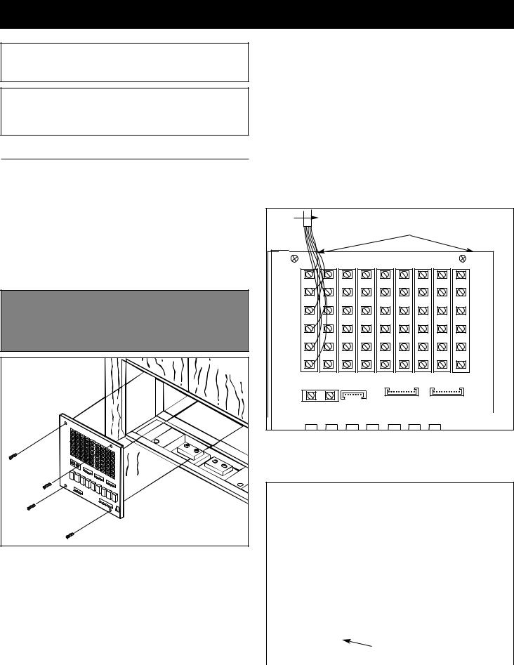
MOUNTING THE TERMINAL BOARD
1.Remove and clean any drywall debris or dust from the rough-in before beginning installation.
2.Refer to Figure 1. Locate the terminal board in the left rear section of the rough-in frame.
3.Use four (4) Nº 6 x 3⁄8“ screws supplied to secure the terminal board to the rough-in frame.
4.Make certain the lower right-hand screw is secure and snug against the ground lug which covers the mounting hole in the terminal board. Do not bend ground lug.
Make sure it is positioned between the screw and terminal board.
IMPORTANT |
|
▲ |
▲ |
DO NOT APPLY POWER TO THE SYSTEM UNTIL ALL CONNECTIONS ARE COMPLETE AT THE MASTER AND REMOTE STATIONS.
FIGURE 1 |
2.Refer to Figure 2. Connect the IW-6 cable from each remote to the appropriate set of terminal screws at the master station’s terminal board. When connecting the cable to the terminal board, be sure to observe the matching of all color codes.
Connect: RED to RED RED/WHT to RED/WHT BLK to BLK
BLK/WHT to BLK/WHT ORN to ORN ORN/WHT to ORN/WHT
Only connect one remote to each set of screw terminals. After completing all connections, check for any shorted wires. Dress cables flat against the terminal board to allow space for the master station to be properly secured.
IW-6
MOUNTING HOLES
RED |
RED/WHT |
BLK |
BLK/WHT |
ORN |
ORN/WHT |
FIGURE 2
3.Refer to installation instructions packaged with the remote stations and remote controls for wiring these units.
4.Refer to Figure 3. Use the Wire Matching Chart if you are retro-fitting a system with the previously used IW-6R cable.
IMPORTANT – WHEN NUTONE MODEL IW-6R WIRING IS USED:
CONNECT TO THE
SCREW TERMINALS
ON THE TERMINAL
BOARD MARKED:
|
|
|
|
|
1 |
ORN |
||
All Remote Stations, Remote Controls, Speaker |
|
|
|
|
||||
|
|
|
|
|
2 |
BLK |
||
|
|
|
|
|
||||
Volume Controls, and Door Speaker Wiring MUST |
|
|
|
|
|
3 |
BLK/WHITE |
|
|
|
|
|
|
||||
Return Directly to the Master Station. DO NOT |
|
|
|
|
|
4 |
ORN/WHITE |
|
|
|
|
|
|
||||
CONNECT WIRING FROM SPEAKER TO SPEAKER! |
|
|
|
|
|
5 |
RED |
|
|
|
|
|
|
||||
|
|
|
|
|||||
|
|
|
|
|
6 |
RED/WHITE |
||
|
|
|
|
|
||||
CONNECTING THE REMOTE WIRING |
||||||||
|
|
|
BLUE STRIPE |
|
||||
1. Dress all remote wiring through the rectangular holes |
|
|
|
FIGURE 3 |
||||
|
|
|
|
|
|
|||
in the upper right and left sides of the rough-in frame. |
|
|
|
|
|
|
|
|
|
|
CONNECTING VOLUME CONTROL WIRING |
||||||
All wiring connections are made to the master station’s |
4 |
|
||||||
terminal board. |
|
|
|
|
|
|
||

INSTALLATION (Continued)
Refer to Figure 4. If a NuTone Volume Control is installed in the system, connect the control’s IW-2 wiring to the ORN and ORN/WHT screw terminals at the master station. Only ONE
NuTone speaker may be connected to each volume control. Each volume control/speaker counts as a remote station. Remember: The maximum remote connections to the Master Station is 9. Adding the optional IAA-440 expansion module will increase the system remote capability to 15 stations.
Refer to the installation instructions packed with the speaker
ORN |
ORN/WHT |
FIGURE 4
NEVER USE 8 OHM STEREO SPEAKERS
WITH THIS SYSTEM!
volume control for wiring this unit.
CONNECTING DOOR SPEAKER WIRING
The Door Speakers connect to the Master Station Terminal Board with twisted pair IW-2 wire.
1.Refer to Figure 5. Connect the two wires from the Door Speaker(s) to the 2 screw terminals marked DOOR SPEAKER on the master station terminal board.
DOOR |
FIGURE 5 |
SPEAKER |
PREPARING MASTER STATION PANEL FOR OPTIONAL DOOR RELEASE PUSHBUTTON
To remove the pushbutton cover, position the master station face up. Be careful not to damage the cables on the back of the unit.
1.Refer to Figure 6. Open the left-hand door on the master station panel.
FIGURE 6 |
2.Cut the 4 retainer webs from the pushbutton cover.
3.Remove cover. The door release pushbutton will be installed and connected after the master panel has been mounted to the rough-in frame.
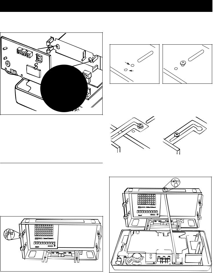
MOUNTING THE OPTIONAL CHIME MODULE IN THE MASTER STATION PANEL
1.Position the master station panel face down on a soft cloth.
2.Refer to Figure 7. Align the optional NuTone IA-28 or IA-29 chime module onto the mounting bracket located in the master station.
|
SNAP IN PLACE |
RED |
|
WIRE |
|
IA-29 ONLY |
FIGURE 7 |
3.Apply firm, but even pressure to each side of the chime module until it snaps into place.
4.Plug the 4 pin connector on the module into the connector located on the master. When properly installed, the ribbon cable will point away from the master station’s circuit boards, as illustrated.
5.Connection from the pushbuttons to the master will be made after the master panel has been mounted.
5
INSTALLATION (Continued)
Model IA-29 Only
1.Refer to Figure 8. Locate the chime selector switch mounting bracket in the master unit.
FIGURE 8 |
2.Remove and set aside the chime selector switch retaining screw located in the master unit.
3.Remove and discard the square foam pads on the chime selector switch PC board connected to the chime module.
4.Slide the PC board into the mounting bracket on the master station.
5.Fasten the chime selector switch PC board with the retaining screw (earlier removed).
MOUNTING THE MASTER STATION
NOTE: If an optional IAA-440 expansion module is to be installed into the IMA-4406 master station, it should be installed before mounting the master station. Refer the installation instruction provided with the expansion module before performing the following mounting steps.
1.Refer to Figure 9. Use two (2) #6x3⁄8˝ screws per bracket to attach each of the four (4) mounting brackets to the rough-in frame. Before tightening, slide the bracket so it is flush with the wall surface (flush with rough-in frame if the rough-in is installed after the wall board). Tighten all eight
(8) screws.
FIGURE 9 |
6 |
2.Refer to Figure 10A and 10B. For rough-in frames which are recessed into the wall opening, insert two (2) shoulder screws (provided) into the front two holes in the rough-in frame. For rough-in frames which are mounted flush with the wall, insert two (2) shoulder screws into the back two holes in the rough-in frame.
BACK HOLE – FOR
FLUSH MOUNTED
ROUGH-INS
FRONT HOLE –
FOR RECESSED
ROUGH-IN
FIGURE 10A
FIGURE 10B |
3.Refer to Figure 11. Attach master panel to rough-in frame by placing mounting hinge keyhole slots over shoulder screw heads in the rough-in frame.
4.Refer to Figure 12. Slide master station panel to the right, then forward until it is flush with the wall surface.
5.Align master panel with rough-in frame.
FIGURE 11 |
|
FIGURE 12 |
6.Refer to Figure 13. Attach support strap to rough-in frame by attaching metal hook into hole in top of rough-in frame. Using pliers, squeeze hook closed. Hook must not come loose when master is later secured.
FIGURE 13 |
 Loading...