NuTone HS-93 User Manual

®
READ AND SAVE THESE INSTALLATION INSTRUCTIONS!
Accessory Switch
MODEL: HS-93 |
|
|
|
|
|
|
|
|
LIGHT VENT HEAT |
|
|||
INSTALLATION |
|
|
|
|||
Used with Heat–Vent–Light |
|
|
COMMON |
|||
Combination. |
|
|
||||
|
|
|
|
|
||
1. |
Install a double–gang box. |
|
|
|
|
|
2. |
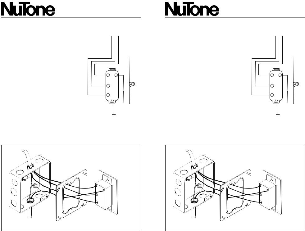
Refer to Figure 1. Run power wiring |
|
|
|
|
|
|
from fuse box or circuit breaker and |
|
|
|
|
|
|
wiring from heat–vent–light wires to |
|
|
LIGHT |
|
|
|
outlet box. |
|
|
|
|
|
3. |
Secure all wires to outlet box with an |
|
|
|
|
|
|
approved box connector. |
|
|
VENT |
|
|
4. |
Dress all leads, leaving |
|
|
|
BLACK |
WHITE |
|
approximately 1/2" of bare wire for |
|
|
HEAT |
||
|
|
|
|
|
||
|
making connections. |
|
|
|
|
|
5. |
Refer to Figure 1. Make wire |
|
|
|
|
|
|
connections. Observe cover plate |
TO |
120vAC, 60Hz |
|
|
|
|
markings (Heat–Vent–Light) when |
|
|
|||
|
HOUSE POWER |
|
FIGURE 1 |
|||
|
making connections. Make sure that |
|
||||
|
|
|
|
|||
the switch and the unit it controls are properly grounded.
6.Refer to Figure 2. Using two supplied screws, secure switch bracket assembly to outlet box adapter plate.
7.Position wall plate over switch assembly and secure with supplied screws.
TO UNIT
2 GANG
BOX
ADAPTER PLATE
USE A SINGLE-GANG BOX ADAPTER PLATE TO COVER DOUBLE GANG BOX. ADAPTER PLATE NOT SUPPLIED WITH SWITCH.
TO 120vAC, |
|
60Hz HOUSE POWER |
FIGURE 2 |
|
 Loading...