


BUILT-IN CENTRAL CLEANING SYSTEM
MODEL: CV-352
GENERAL INFORMATION |
..............2 |
LAYOUT AND PLANNING............... |
2 |
Examples ........................................ |
2 |
Locating the Power Unit.................. |
3 |
Locating the Wall Inlets................... |
3 |
Tubing ............................................. |
3 |
INSTALLATION IN |
|
NEW CONSTRUCTION.................... |
4 |
Wall Inlet Rough-In ......................... |
4 |
Installing the Tubing........................ |
4 |
Installation Hints............................ |
4 |
Tubing Installation......................... |
5 |
Wall Inlet Installation ....................... |
6 |
Model 360 Wall Inlet ..................... |
6 |
Model 330 Wall Inlet ..................... |
6 |
Power Unit Installation .................... |
7 |
Dimensional Chart ........................ |
7 |
Mounting ....................................... |
7 |
Tubing connections....................... |
7 |
Wiring............................................ |
7 |
INSTALLATION IN |
|
EXISTING CONSTRUCTION ........... |
8 |
Layout and Planning ....................... |
8 |
Locating Access Keys..................... |
8 |
Wall Inlet Installation ....................... |
8 |
Model 330 Wall Inlet ................... |
10 |
FLOOR INLET INSTALLATION..... |
10 |
FINAL SYSTEM CHECK................ |
11 |
GENERAL INFORMATION
The NuTone Central Cleaning System consists of a Central Power Unit, PVC Tubing, PVC Fittings, automatic switch operated Wall Inlets, a flexible hose and various cleaning attachments.
The Power Unit is designed to be wall mounted away from the living area of the home and connected to the living area by means of permanently installed In-Wall tubing and fittings.
LAYOUT AND PLANNING EXAMPLES
As an aid in planning the installation, look at the following examples.
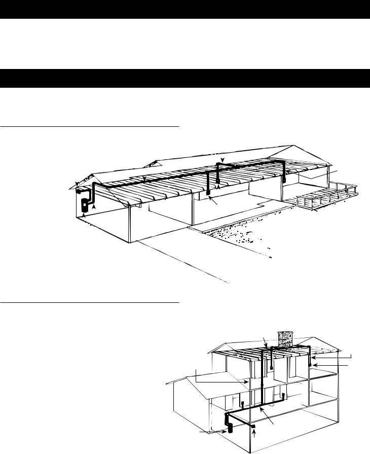
THE RANCH STYLE HOUSE
Here the power unit is mounted in the
garage. The intake and exhaust tubing, |
TRUNK LINE |
|
|||||||
the only exposed |
|
|
|
|
|
|
|
|
|
tubing in the |
EXHAUST |
|
|
|
|
||||
|
|
|
|
||||||
installation, runs up |
|
|
|
|
|
|
|
|
INLET LINE |
the garage wall and |
|
|
|
|
|
|
|
|
|
|
|
|
|
|
|
|
|
|
|
into the attic. |
|
|
|
|
|
|
|
|
|
|
|
|
|
|
|
|
|
|
|
The trunk line runs |
|
|
|
|
|
|
|
|
|
|
|
|
|
|
|
|
|
|
|
horizontally through |
|
|
|
|
|
|
|
|
|
the attic from the |
|
|
|
|
|
|
|
|
|
|
|
|
|
|
|
INLETS |
|||
power unit to the |
|
|
|
|
|
|
|||
|
|
|
|
|
|
|
|
FIGURE 1 |
|
farthest inlet location. |
|
|
|
|
|
|
|
|
|
|
|
|
|
|
|
|
|
||
Branch lines spread |
|
|
|
|
|
|
|
|
|
throughout the attic, |
|
POWER |
|
|
|
|
|
||
connecting the trunk line |
UNIT |
|
|
|
|
|
|||
|
|
INTAKE |
|
|
|
|
|||
to the inlet tubing. Each inlet tube is threaded
vertically through an inside wall. Located in hallways,
and in large rooms, the inlets are placed to provide maximum access to all cleaning areas. See Figure 1.
THE TWO-STORY HOUSE
In this installation, the power unit is mounted in the basement, conveniently located for shop use and messy cleaning jobs. The intake tubing runs up the basement wall and connects to the main trunk line, which runs along the unfinished basement ceiling. Two first-floor inlets are connected to the trunk line vertical inlet lines run through interior walls. In the center of house, a vertical branch
line runs from the basement trunk line, through stacked closets, up into the attic. A second trunk line runs
across the attic and two branch lines connect to inlet lines which are dropped down through upstairs interior walls.
See Figure 2.
The double-trunk line system is commonly used in two-story houses. Finding the “key” to an accessible vertical area is the most important step in this kind of installation.
VERTICAL
BRANCH
LINE
INTAKE

POWER
UNIT
ATTIC
TRUNK
LINE
INLET
LINE
INLET
BASEMENT
TRUNK LINE
EXHAUST
FIGURE 2
2
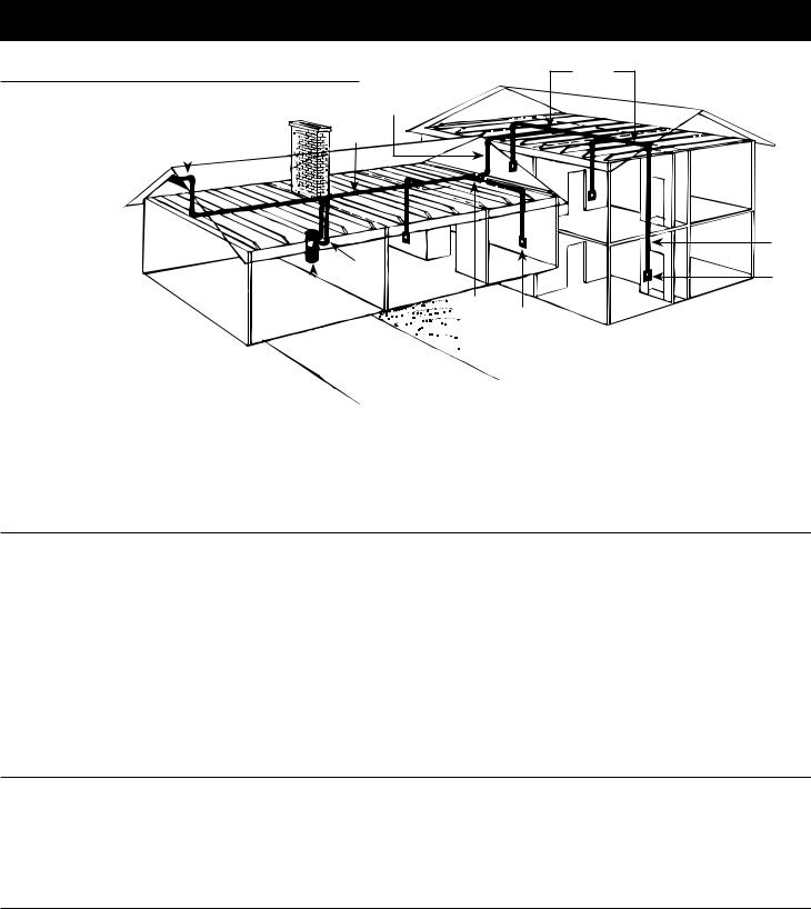
THE SPLIT-LEVEL HOUSE
Like the two-story commonly calls for a
Here, the power unit |
|
|
|
TRUNK |
EXHAUST |
|
LINE |
||
located in the garage |
|
|
||
|
|
|
|
|
The intake tubing runs |
|
|
|
|
|
|
|
|
|
exposed up the |
|
|
|
|
garage wall and |
|
|
|
|
into the ground level |
|
|
|
|
section's attic. |
|
|
|
|
Two branch lines |
|
|
|
|
connect this part |
|
|
|
INTAKE |
|
|
|
||
of the trunk line to |
|
|
|
|
|
|
POWER |
||
lines which |
|
|
||
|
|
UNIT |
||
are dropped |
|
|
|
|
inside interior walls. |
|
|
|
|
branch line runs to |
|
|
|
|
where the trunk line |
|
|
|
|
branches into a T- |
|
|
|
|
This trunk line connects |
|
|
|
|
upstairs inlet lines and to one inlet line which drops through an upstairs wall and down into
the third-level utility room. This last inlet services
both the utility room and a large L-shaped recreation room.
See Figure 3.
BRANCH |
LINES |
INLET
LINE
INLET
BRANCH
LINE INLET
LOCATING THE POWER UNIT
•Locate the power unit away from the general living area.
•The power unit is equipped with an inlet. When planning, remember the power unit has an inlet for a garage, basement, utility room, etc.
•Locate the power unit in an accessible area for changing the soil bag and periodically cleaning the secondary filter.
•Locate the power unit within six feet of a grounded electrical outlet. The power unit requires a 120 vAC power source.
•Do not locate the power unit close to a source of extreme heat (i.e., water heater) or in an area with an ambient high temperature (i.e., attic, furnace room).
•If the power unit is located in a closet or a small utility room, make sure the area is well-ventilated (i.e., with door louvers).
•The power unit should be exhausted to the outside. The
exhaust should not be vented into a wall, a ceiling or a concealed space in the house. The exhaust line should be terminated outside the home, using Model 393 Wall Cap or a roof vent.
WARNING
Power unit must not be mounted in a high ambient temperature area such as attic, furnace room, etc.
LOCATING THE WALL INLETS
•Locate inlets on interior walls.
•Choose central locations which allow several rooms to be cleaned from a single inlet.
•Locate inlets centrally so that a maximum area can be cleaned with the 30' hose.
•Locate inlet within six feet of an electrical outlet to allow use of optional current-carrying hose.
•Be sure tubing will not obstruct electrical, plumbing or other mechanical installation.
•Be sure inlets will not be blocked by doors or furniture.
TUBING
•The installation should consist of a main trunk line running from the farthest wall inlet to the power unit location, with branch lines running to each additional inlet. Beginning at the area farthest from the power unit, choose a tentative inlet location. measure (30 feet for 30 foot hose) from the proposed inlet location to the farthest corner of the rooms to be cleaned by that inlet to determine if inlet location is proper.
•Move tentative inlet location if necessary. Use the same
procedure to determine each additional inlet location, always working toward the power unit.
•Generally, an installation will require 3 to 4 inlets and 16 to 20 feet of tubing per inlet. It is suggested that a floor plan be used to more accurately determine the quantity of materials needed.
NOTE: Conventional metal or plastic strapping should support the exhaust tubing when a muffler is used, or at the joints of long runs of tubing where another means of support is not available.
3

INSTALLATION IN NEW CONSTRUCTION
WALL INLET ROUGH-IN
1.Once the locations for wall inlets have been determined, mount all inlet brackets.
2.To locate bracket on wall stud, measure approximately 18" up from finished floor level. (Height may vary according to individual preference.)
3.Refer to Figure 4. Model 361 for using 360 inlet. Nail bracket to side of stud so that front edge of bracket is flush to front of stud. (The bracket may also be nailed to the front edge of the stud. For front stud mounting, use locating tabs on bracket for proper alignment.)
4.Refer to Figure 5. Model 329 for use with 330 inlets. Remove cardboard from plaster guard frame. Using four (4) provided screws, attach the appropriate flanged fitting and inlet seal to back of inlet.
5.Replace cardboard in plaster guard frame.
6.When using Model 329 glue elbow to mounting plate.
NOTE: Configuration of spacer may vary depending upon installation.
NOTE: When using the Model 361 inlet bracket on walls thinner than 1⁄2", use a 1⁄4" spacer (not furnished) between the wall and the inlet bracket. See Figure 5A.
Spacer may be made from plywood, masonite, etc. Contact cement may be used to hold spacer in place during assembly.
FIGURE 5 |
|
|
MODEL 361 |
MODEL 329 |
SIDE |
FACE |
|
||
|
MOUNTING |
MOUNTING |
FIGURE 4 |
2 3/8" |
1 13/16" |
|
|
INLET MOUNTING |
SPACER |
WALL LESS THAN |
|
|
|||
1/4" |
1/2" THICK. |
||
BRACKET |
|||
|
|
31/4" PLASTER
21/4" 
 GUARD
GUARD
HOLE
FIGURE 5A
INSTALLING THE TUBING
INSTALLATION HINTS
Use the following installation guidelines when installing the tubing.
1.Start tubing installation at farthest inlet and work toward the power unit.
2.Tubing run to the power unit should be as straight as possible.
3.When assembling sections with elbows and tees, make sure the curve in the fitting is aligned so that the air flows toward the power unit.
4.Branch lines should always join the trunk line from above or from the same level. Never join a branch line from an angle below the trunk line.
5.Secure tubing to joists or studs.
6.Refer to Figure 20 on page 7. Run low voltage wiring and secure wiring to tubing. Leave approximately 6" of wire for connection to each inlet.
|
MODEL 361 MOUNTING |
|
|
|
21/2" DIA. HOLE |
|
|
|
THROUGH SOLE PLATE |
|
|
23/8" |
|
|
113/16" |
|
113/16" |
|
113/16" |
SIDE |
|
|
FACE |
MOUNTING |
|
|
MOUNTING |
|
MODEL 329 MOUNTING |
|
|
|
2" |
21/2" DIA. HOLE |
|
|
THROUGH SOLE PLATE |
||
|
|
|
2"-382s |
|
113/16" |
25/8-382 |
|
FIGURE 6 |
FACE |
|
|
MOUNTING |
|
|
|
4
 Loading...