


INSTALLATION
INSTRUCTIONS
Built-In Central Cleaning System
MODELS: CV554, CV556, and CV570
SYSTEM PLANNING AND LAYOUT . . . . . . . . . . . . . . . . . . . . |
. .2 |
Examples . . . . . . . . . . . . . . . . . . . . . . . . . . . . . . . . . . . . . . . . . . |
. .2 |
Locating the Power Unit . . . . . . . . . . . . . . . . . . . . . . . . . . . . . . . |
. .3 |
Tubing and Wall Inlet Location . . . . . . . . . . . . . . . . . . . . . . . . . |
. .3 |
Locating Access Keys in Existing Construction . . . . . . . . . . . . . |
. .3 |
INSTALLATION IN NEW CONSTRUCTION . . . . . . . . . . . . . . . . |
4-8 |
Wall Inlet Rough-In . . . . . . . . . . . . . . . . . . . . . . . . . . . . . . . . . . |
. .4 |
Installing the Tubing . . . . . . . . . . . . . . . . . . . . . . . . . . . . . . . . . . |
. .5 |
Wall Inlet Installation |
|
Model 360 Wall Inlets . . . . . . . . . . . . . . . . . . . . . . . . . . . . . . |
. .6 |
Model 330 Wall Inlets . . . . . . . . . . . . . . . . . . . . . . . . . . . . . . |
. .6 |
Model CI390 Wall Inlet (Electrified Inlet) . . . . . . . . . . . . . . . . |
. .7 |
POWER UNIT INSTALLATION . . . . . . . . . . . . . . . . . . . . . . . . . . .8
Dimensional Chart . . . . . . . . . . . . . . . . . . . . . . . . . . . . . . . . . . . .8
Mounting . . . . . . . . . . . . . . . . . . . . . . . . . . . . . . . . . . . . . . . . . . .8
Tubing Connections at Power Unit . . . . . . . . . . . . . . . . . . . . . . .8
Wiring . . . . . . . . . . . . . . . . . . . . . . . . . . . . . . . . . . . . . . . . . . . . . .8
INSTALLATION IN EXISTING CONSTRUCTION . . . . . . . . . . . |
9-10 |
Wall Inlet Installation |
|
Model 360 Wall Inlets . . . . . . . . . . . . . . . . . . . . . . . . . . . . . |
. . .9 |
Model 330 Wall Inlets . . . . . . . . . . . . . . . . . . . . . . . . . . . . . |
. .10 |
FLOOR INLET INSTALLATION . . . . . . . . . . . . . . . . . . . . . . .10-11
FINAL SYSTEM CHECK . . . . . . . . . . . . . . . . . . . . . . . . . . . . . . . .11
WARRANTY . . . . . . . . . . . . . . . . . . . . . . . . . . . . . . . . . . . . . . . . .12

SYSTEM PLANNING AND LAYOUT
The NuTone Central Cleaning System consists of a Power Unit, PVC Tubing and Fittings, Wall Inlets, a flexible Hose and various cleaning Attachments.
The Power Unit is designed to be wall-mounted away from the living area of the home and connected to the living area by means of permanently installed in-wall tubing, fittings and inlets.
Generally, an installation will require 3 to 4 inlets and 16 to 20 feet of tubing per inlet. It is suggested that a floor plan be used to more accurately determine the quantity of materials needed.
As an aid in planning the installation in either new or existing construction, look at the following examples. You should be able to adapt the examples shown to your specific home layout.
THE RANCH STYLE HOUSE
Here the power unit is mounted EXHAUST in the garage. The intake and
exhaust tubing, the only exposed
tubing in the installation, runs up the garage wall and into the attic. The trunk line runs horizontally
through the attic from the power unit to the farthest inlet location. Branch lines spread throughout the
attic, connecting the trunk line to the
inlet tubing. Each inlet tube is
INTAKE
threaded vertically through an inside Located in hallways, and in large provide maximum access to all cleaning
ATTIC
TRUNK
LINE
VERTICAL
BRANCH
LINE
INTAKE
BASEMENT
TRUNK LINE
POWER
UNIT
EXHAUST
BRANCH LINE
TRUNK LINE
INLET LINE
INLETS
FIGURE 1
THE TWO-STORY HOUSE
A double-trunk line system is commonly used in two-story houses.
INLET
LINE In the installation shown at left, the power unit is mounted in the
basement. The intake tubing runs up the basement wall and INLET connects to the main trunk line, which runs along the unfinished
basement ceiling. Two first-floor inlets are connected to the basement trunk line by vertical inlet lines run through interior walls. In the center of the house, a vertical branch line runs from the basement trunk line,
through stacked closets, up into the attic. A second trunk line runs across the attic and two branch lines connect to inlet lines which are dropped down through upstairs interior walls. See Figure 2.
FIGURE 2
EXHAUST
FIGURE 3
THE SPLIT-LEVEL HOUSE
BRANCH
LINES
VERTICAL
BRANCH
LINE
TRUNK
LINE
|
|
INTAKE |
|
|
|
|
|
|
|
|
|
|
|
|
|
|
|
POWER |
|
|
|
|
|
BRANCH |
|
|
|||
UNIT |
|
|
|||
|
|||||
|
|
LINE INLET |
|||
Like the two-story house, the split level installation commonly calls for a two-level trunk line. Here, the power unit is located in the garage.
The intake tubing runs exposed up the garage wall and into the ground level section's attic. Two branch lines
|
connect this part of the trunk |
|
line to inlet lines which are |
|
dropped inside interior walls. A |
|
vertical branch line runs to the |
|
upstairs attic, where the trunk |
INLET |
line branches into a T-shape. |
LINE |
This trunk line connects to two |
|
|
INLET |
upstairs inlet lines and to one |
|
inlet line which drops through |
an upstairs wall and down into the third-level utility room to service this entire level. See Figure 3.
2
LOCATING THE POWER UNIT
•Locate the power unit away from the general living area in an accessible location for emptying the lower dirt cannister and periodically cleaning the filter.
•When planning, remember the power unit is equipped with an inlet to service a garage, basement, utility room, etc., wherever it is located.
•Locate the power unit within six feet of a grounded electrical outlet. The power unit requires a 120vAC power source.
•Do not locate the power unit close to a source of extreme heat (i.e., water heater) or in an area with a high ambient temperature (i.e., attic, furnace room).
•If the power unit is located in a closet or a small utility room, make sure the area is well-ventilated (i.e., with door louvers).
•Exhausting the power unit to the outside is recommended for optimal performance but is not required. The exhaust should not be vented into a wall, a ceiling or a concealed space in the house. If the exhaust line is vented outside the home, Model 393 Wall Cap or a roof vent are recommended.
WARNING: Power unit must not be mounted in a high ambient temperature area such as attic, furnace room, etc.
TUBING AND WALL INLET LOCATIONS
1.Locate inlets on interior walls, choosing central locations which allow several rooms to be cleaned from a single inlet using a 30 foot long hose.
2.The tubing installation should consist of a main trunk line running from the farthest wall inlet to the power unit location, with branch lines running to each additional inlet. Keep all tubing lines as straight as possible and use as few fittings as possible. Beginning at the area farthest from the power unit, choose a tentative inlet location. Measure 30 feet from the proposed inlet location to the farthest corner of the rooms to be cleaned by that inlet to determine if inlet location is proper.
3.If working from blueprints (or building plans drawn at 1⁄4" = 1 ft. scale), use a 71⁄2" chain as your guide to determine inlet locations.
4.Move tentative inlet location if necessary. Use the same procedure to determine each additional inlet location, always working toward the power unit.
5.Be sure tubing will not interfere with electrical, plumbing or other mechanical installations.
6.Locate inlets within six feet of an electrical receptacle to allow use of optional current-carrying hose.
7.Be sure inlets will not be blocked by doors or furniture.
LOCATING ACCESS KEYS IN
EXISTING CONSTRUCTION
Let's say, for example, you have a two-story house and you want to locate the power unit in the basement. If you can't find interior walls on both the first and second floors which line up and are free from obstacles. How do you get from the basement to the attic?
Unless your home is a ranch-style house where a single trunk line can run directly through the attic or basement, you should first investigate your house to find the key to running your tubing from level to level. Look for an accessible area free from obstructions that will accommodate the 2" tubing.
If you understand how your existing home is constructed, it can be relatively easy to find access routes to run the tubing. Refer again to the illustration on page 2 as you consider your home construction.
Some of the keys you might find in your home are illustrated here.
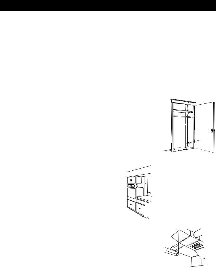
Stacked Closets or Laundry Chute. Many homes will have an upstairs closet located directly above a downstairs closet. It is easy to run the tubing from one floor level to another inside these stacked closets. In these installations the tubing is often left exposed inside the closets. See Figure 4. A laundry chute could also provide access from basement to upper floors.
TUBING
FIGURE 4
Built-In Appliances. You will often find a hollow space behind built-in kitchen appliances. If this space lines up with an obstruction-free interior wall above or a closet, this might be a key to your installation. See Figure 5.
You may also want to consider running exposed tubing through cabinets or cupboards.
FIGURE 5
Cold-Air Return. A cold-air return often provides a straight run from basement to other levels of the house. See Figure 6.
The ductwork is easily cut for access. Seal around the tube when completing the installation.
FIGURE 6
3
INSTALLATION IN NEW CONSTRUCTION
WALL INLET ROUGH-IN
Once the locations for wall inlets have been determined, mount all inlet brackets.
1.Choose the appropriate mounting bracket for the inlet being installed. (See chart.)
NuTone Inlet |
Rough-in |
330 Series |
329 |
360 Series |
361 |
CI390 Series Electrified Inlet |
CI390RK |
|
|
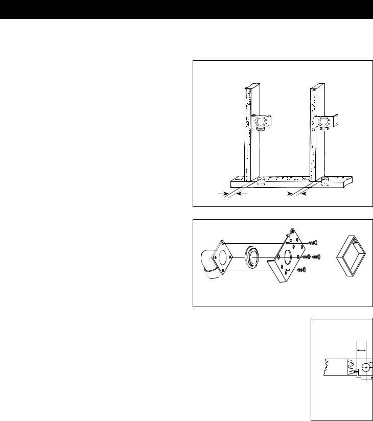
2.To locate bracket on wall stud, measure approximately 18" up from finished floor level. (Height may vary according to individual preference.)
MODEL 361 (FOR USE WITH 360 INLETS)
3.Refer to Figure 7. Nail bracket to side of stud so that front edge of bracket is flush to front of stud. (The bracket may also be nailed to the front edge of the stud. See face mounting illustrated. For face mounting, use locating tabs on bracket for proper alignment.)
4.Refer to Figure 8. Remove cardboard from plaster guard frame. Using four (4) provided screws, attach the appropriate flanged fitting and inlet seal to back of inlet.
5.Replace cardboard in plaster guard frame.
MODEL 329 (FOR USE WITH 330 INLETS)
6.When using Model 329, glue elbow to mounting plate. Attach to stud as shown in Figure 9.
|
MODEL 361 |
SIDE |
FACE |
MOUNTING |
MOUNTING |
23/8" |
|
|
|
113/16" |
|
|
FIGURE 7
FIGURE 8 |
M |
T |
23/8" |
SIDE |
MOUNTING |
M |
FIGURE 9
4
INSTALLATION IN NEW CONSTRUCTION (continued)
INSTALLING THE TUBING
Use the following installation guidelines when installing tubing.
1.Start tubing installation at farthest inlet and work toward the power unit.
2.Tubing run to the power unit should be as straight as possible.
3.When assembling sections with elbows and tees, make sure the curve in the fitting is aligned so that the air flows toward the power unit.
4.Branch lines should always join the trunk line from above or from the same level. Never join a branch line from an angle below the trunk line.
5.Refer to Figure 28 on page 8. Run low voltage wiring (Model 376-UL) and secure wiring to tubing as tubing is installed. Model CF-380 Pipe Support can be used to support long runs of tubing (position near joists) and to clip wire along tubing. Secure tubing to joists or studs. Leave approximately 6" of wire for connection to each inlet.
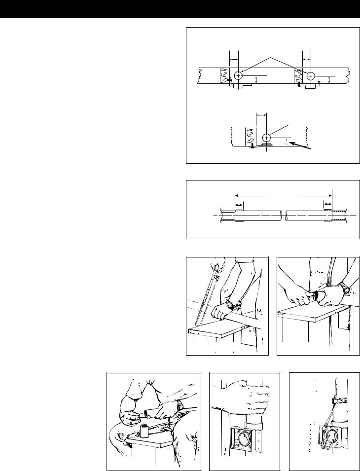
6.Cut a 21⁄2" diameter hole in sole plate, header or stud directly in line with opening of inlet bracket fitting.
Note Figure 6 for center line dimensions.
7.Refer to Figure 11. Measure length of tubing needed to connect inlet to trunk line. Allow approximately 3⁄4" of tubing for inserting into fittings.
8.Refer to Figure 12. Cut tubing, keeping cut square.
9.Refer to Figure 13. Remove burrs from both inside and outside of tubing.
10.Before cementing, pre-assemble section to inlet fitting, check for proper length.
|
MODEL 361 MOUNTING |
|
|
|
21/2" DIA. HOLE |
|
|
|
THROUGH SOLE PLATE |
|
|
23/8" |
|
|
113/16" |
|
113/16" |
|
113/16" |
SIDE |
|
|
FACE |
MOUNTING |
|
|
MOUNTING |
|
MODEL 329 MOUNTING |
|
|
|
2" |
21/2" DIA. HOLE |
|
|
THROUGH SOLE PLATE |
||
|
113/16" |
2" - 382S |
|
|
|
|
|
|
FACE |
|
25⁄8" - 382 |
FIGURE 10 |
MOUNTING |
|
|
|
INCLUDE FITTING |
|
|
RECESS IN |
|
|
MEASUREMENT |
3/4" |
3/4" |
TUBING MEASUREMENT |
|
|
|
|
FITTING |
PVC TUBING |
FITTING |
|
|
|
FIGURE 11 |
|
|
11.Refer to Figure 14. Apply PVC cement (Model 379) to outside of tubing. Coat tubing approximately 1" back. Take care to keep cement from inside of tube.
12.Refer to Figure 15. Insert tubing into fitting with a twisting motion to evenly spread cement. Be sure tubing is firmly seated in fitting.
13.If fittings have been attached to tubing at the end opposite the inlet bracket, be sure alignment is proper before cement sets.
14.Refer to Figure 16. Tape wire to tubing to hold in place and insert through hole in inlet bracket.
15.Connect each inlet line and branch line into main trunk line. Complete low voltage wiring as main trunk line is continued back to power unit.
FIGURE 12 |
FIGURE 13 |
Caution: When tubing is run through the wall stud, sole plate, headers - or anywhere that building materials will be attached - place a nail plate (Model 378) over that area
(on both sides if necessary) to prevent nails from piercing tubing.
FIGURE 14 |
FIGURE 15 |
FIGURE 16 |
5
INSTALLATION IN NEW CONSTRUCTION (continued) |
|
|||
WALL INLET INSTALLATION |
|
|
|
|
MODEL 360 WALL INLET (361 Rough-In) |
|
|
|
|
1. Remove the cardboard plaster guard. |
|
|
|
|
2. Refer to Figure 17. For some drywall or panel construction, the |
|
|
|
|
plaster frame will extend beyond the finished wall. In this case, |
|
|
|
|
remove plaster frame from mounting bracket by removing |
|
|
|
|
mounting screws. |
|
|
|
|
NOTE: When using the Model 361 inlet bracket on walls thinner |
|
|
|
|
than 1⁄2", use a 1⁄4" spacer (not furnished) between the wall and the |
FIGURE 17 |
|
FIGURE 18 |
|
inlet bracket. See Figure 20. Spacer may be made from plywood, |
|
|||
|
|
|
||
Masonite™, etc. Contact cement may be used to hold spacer in |
|
|
|
|
place during assembly. Configuration of spacer may vary |
|
|
|
|
depending upon installation. |
|
|
|
|
3. Refer to Figure 18. Connect 2-conductor low voltage wire to |
|
|
|
|
terminal screws on back of wall inlet. Cap off both wires using |
|
|
|
|
wire nut (supplied). |
|
|
|
|
4. Guide excess wire back through the hole in inlet bracket and |
|
|
|
|
flanged fitting |
|
|
|
|
5. Refer to Figure 19. Place inlet into mounting bracket and |
|
|
|
|
secure. |
|
|
|
|
NOTE: when wall inlets are installed in walls that are less |
|
|
|
|
than 1⁄2" thick or when inlets are installed back-to-back in a |
INLET MOUNTING |
SPACER |
WALL LESS THAN |
|
wall, the tube of the wall inlet may extend into elbow area of |
|
|||
1/4" |
1/2" THICK. |
|||
BRACKET |
||||
the flanged fitting and cause blockage. Shorten the wall inlet |
|
|
||
|
|
|
||
tube to prevent this condition. Refer to Figure 21. |
|
|
|
|
For extra thick walls, use Model 399 Extension Sleeve to connect inlet to the flanged fitting.
MODEL 330 WALL INLET (329 Rough-in) |
2 |
1 |
/4" |
31/4" |
PLASTER |
|
See Figure 23. |
|
|
GUARD |
|||
FIGURE 20 |
|
|
|
HOLE |
||
1. |
Connect 2-conductor low voltage wire to terminal screws on |
|
|
|
|
|
|
|
|
|
|
||
|
back of wall inlet. |
|
|
|
MODEL 365 |
|
2. |
Align inlet mounting holes with holes in mounting plate. |
|
|
|
|
|
|
|
|
DOUBLE FLANGED |
|||
3. |
Place inlet into mounting plate and secure with two provided |
|
|
|
TEE |
WALL |
|
|
|
|
|||
|
screws. |
|
|
|
|
INLET |
|
|
|
|
|
|
|
WALL |
SHORTEN |
MOUNTING |
FIGURE 21 |
|
BRACKET |
|
INLET |
MOUNTING |
|
|
|
|
|
PLATE |
6 |
|
FIGURE 22 |
|
|
INSTALLATION IN NEW CONSTRUCTION (continued)
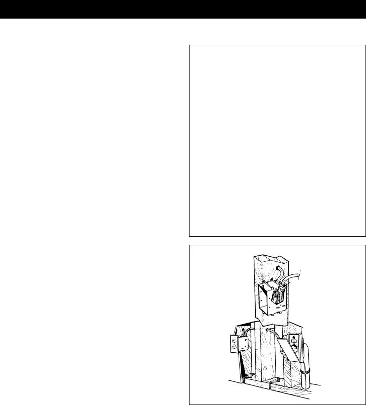
CI-390 ELECTRAVALVE™ ELECTRIFIED INLET INSTALLATION (CI-390RK Rough-In) (Not available in Canada)
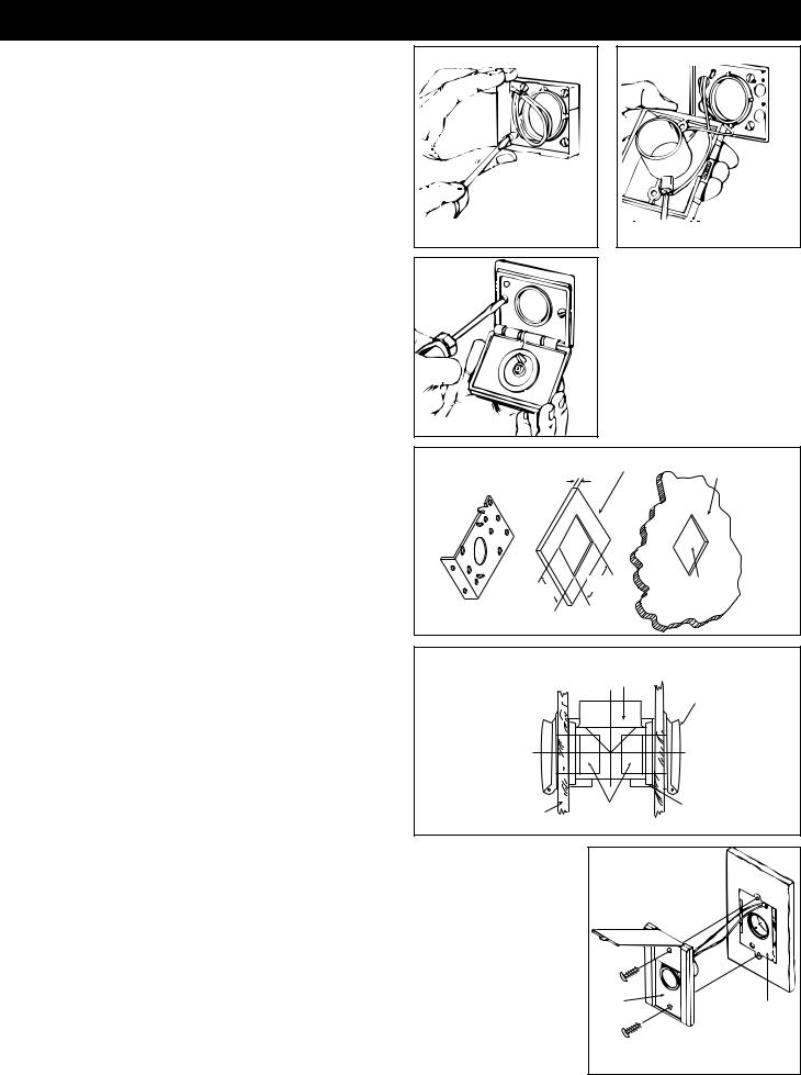
1.See Figure 23. Fasten the mounting plate to a stud within three studs (48") of an electrical outlet box. Measure and mark the wire 10" from the plug (A). Feed the wire through the top hole in the mounting plate (just above the circular opening). Snap the molded plug into the mounting plate as pictured (B). This will keep it secure and out of harm’s way during drywalling and finishing. Line up the wire at the previously measured 10" mark with the strain of relief channel on the back of the mounting plate. Secure it in place with the supplied wire tie (C).
2.Run the inlet wire to the adjacent electric box. If you must run wire through a stud, drill directly through the center of the stud (D).
3.See Figure 24. Place the exposed ends of the two wires into the electrical box through a strain relief channel (E). Tighten the strain relief channel (do not overtighten) on the white sheathing leaving 1/2" of this sheathing exposed inside of the outlet box.
Fold the 6" of black and white wire into the outlet box. Leave the wires to be connected by the electrician when plug receptacles are being installed. (Attention: Power tools such as routers are not recommended for use with the inlet installation, as removal of drywall with these devices may cause damage to the mounting plate and/or inlet plug).
4.Once drywall and finishing processes have been completed, remove molded plug from mounting plate (with the aid of a slot screwdriver) and snap it into the wing slot at the back of the inlet (F). (Please note: molded plug fits one way only, with the narrow opening at the top). Insert inlet into the mounting plate and secure inlet to mounting plate with screws provided.
NOTE: All electrical devices such as the electrified inlet should be reported to the construction electrician for listing on the inspection report for building inspection purposes.
NOTE: Plumb inlet to tubing using NuTone
Model 382-S 90° Ell fitting.
FIGURE 23
E
D
FIGURE 24
7
 Loading...