


765H110L
Page 1
MODEL 765H110L
VENTILATION FAN
WITH HEATER & LIGHT
READ AND SAVE THESE INSTRUCTIONS
IMPORTANT INSTRUCTIONS
READ ALL INSTRUCTIONS BEFORE INSTALLING OR
USING THIS HEATER.
To reduce the risk of fire, electric shock, or injury to persons, observe the
following:
1. Use this unit only in the manner intended by the manufacturer. If you have
questions, contact the manufacturer at the address or telephone number
listed in the warranty.
2. Before servicing or cleaning unit, switch power off at service panel and
lock the service disconnecting means to prevent power from being
switched on accidentally. When the service disconnecting means cannot
be locked, securely fasten a prominent warning device, such as a tag, to
the service panel.
3. Installation work and electrical wiring must be done by a qualified
person(s) in accordance with all applicable codes and standards, includ-
ing fire-rated construction codes and standards.
4. When cutting or drilling into wall or ceiling, do not damage electrical wiring
and other hidden utilities.
5. This heater is hot when in use. To avoid burns, do not let bare skin touch
hot surfaces. Keep combustible materials, such as furniture, pillows, bed-
ding, papers, clothes, etc. and curtains at least 3 feet (0.9 m) from the
front of the heater.
6. Extreme caution is necessary when any heater is used by or near chil-
dren or invalids and whenever the heater is left operating and unattended.
7. Do not operate any heater after it malfunctions. Disconnect power at ser-
vice panel and have heater inspected by a reputable electrician before
reusing.
8. Do not use outdoors.
9. To disconnect heater, turn controls to off, and turn off power to heater
circuit at main disconnect panel (or operate internal disconnect switch, if
provided).
10. Do not insert or allow foreign objects to enter any ventilation or exhaust
opening, as this may cause an electric shock or fire, or damage the heat-
er.
11. To prevent a possible fire, do not block air intakes or exhaust in any man-
ner.
12. A heater has hot and arcing or sparking parts inside. Do not use it in
areas where gasoline, paint, or flammable vapors or liquids are used or
stored.
13. Use this heater only as described in this manual. Any other use not rec-
ommended by the manufacturer may cause fire, electric shock, or injury
to persons.
14. This product must be grounded.
15. Do not install heater in a tub or shower enclosure.
16. THIS PRODUCT MUST BE MOUNTED IN A FLAT CEILING ONLY. In-
stallations in ceilings 9-feet high or less will provide maximum comfort.
DO NOT MOUNT THIS PRODUCT IN A WALL.
17. Install heater in ceiling only - at least 6 inches from any wall.
18. Do not connect heater to dimmer switch or speed control.
19. Provide a separate 20 AMP circuit. Use 12 GA. power cable of type which
meets code. Use supply wiring rated for at least 90
O
C.
20. For greatest efficiency, install heater so heat is directed toward tub or
shower area. Avoid directing toward walls or windows.
SAVE THESE INSTRUCTIONS
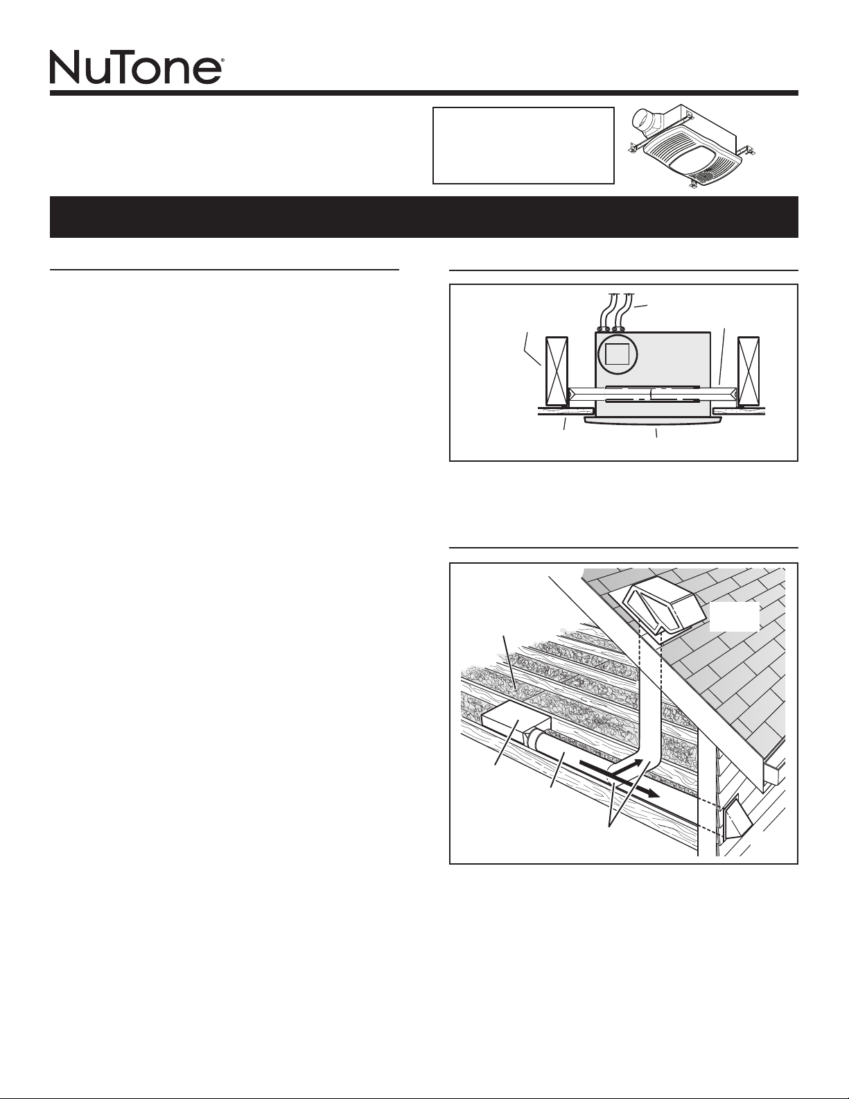
PLAN THE INSTALLATION
The unit will operate most quietly and efficiently when located
where the shortest possible duct run and minimum number of
elbows will be needed.
Use a roof cap or wall cap that has a built-in damper to reduce
backdrafts.
Plan to supply the unit with proper line voltage and appropriate
power cable.
ROOF
CAP
*
4-IN. ROUND
ELBOW(S) *
4-IN.
ROUND
DUCT *
WALL
CAP
*
*
Purchase
separately
INSULATION
(Can be placed
around and over
housing.)
HOUSING
TYPICAL INSTALLATION
HOUSING
CEILING
JOIST, TRUSS,
OR I-JOISTS
MOUNTING
CHANNELS
GRILLE
CEILING
MATERIAL
POWER
CABLES
Housing mounted to joists, trusses, or I-joists.
Up to 24-inches on-center.
For Warranty Statement, Service
Parts, Technical Support, or to
Register your product, please
visit our website or call:
NuTone.com 888-336-6151.

Page 2
MODEL 765H110L
INSTALLATION
2. Mount housing.
Extend hanger bars to the width of the framing. Hold fan
in place with the hanger bar tabs wrapping around the
bottom edge of the framing.
Nail fan to framing or fasten with screws (not provided)
through holes near nails.
* To ensure a noise-free mount: Secure hanger bars
together with screws or use a pliers to crimp mounting
channels tightly around hanger bars.
1. Insert hanger bars.
Four (4) sliding hanger bars are provided to allow for
accurate positioning of housing anywhere between
framing. They can be used on all types of framing (I-joist,
standard joist, and truss construction) and span up to 24”.
Slide hanger bars into channels on housing. Make sure
hanger bar tabs face “up” as shown.
3. Attach
damper
/ duct
connector to
housing.
Snap damper /
duct connector
onto housing.
Make sure
connector is flush
with top of housing
and damper flap
falls closed.
TAB
CHANNEL
HANGER
BARS
HANGER
BARS
CHANNEL
BOTTOM EDGE
OF FRAMING
* SCREW (2)
HOLE FOR OPTIONAL
SCREW MOUNTING (4)
NAIL (4)
WARNING: To reduce the risk of fire, do not store or use
gasoline or other flammable vapors and liquids in the vicinity
of the heater.
CAUTION: High temperature, risk of fire, keep electrical cords,
drapery, furnishings, and other combustibles at least 3 feet
(0.9 m) from the front of the heater and away from the side
and rear.
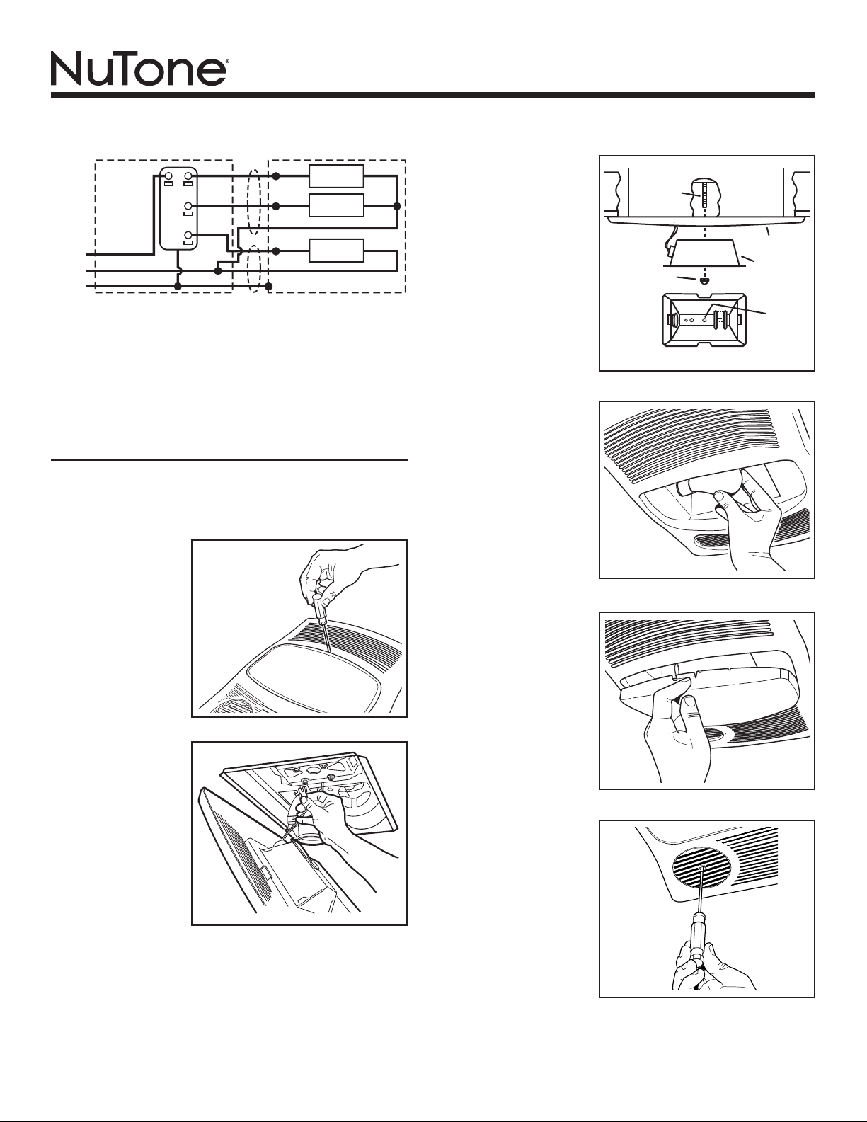
CONNECT WIRING
GREEN
WHITE
to
WHITE
HEAT
LIGHT
GROUND
120 VAC LINE IN
BLACK
BLACK
FAN
RED
WIRING PLATE
FROM VENTILATOR
VENTILATOR
HOUSING
LIGHT
&
FANHEAT
BLACK to BLACK
(Fan)
WHITE to WHITE
RED to BLUE
(Light)
BLACK to RED
(Heat)
WHITE to WHITE
BLACK
CAUTION
RATING
SPECIFICATIONS
Each two-position
rocker switch is rated 15
A @ 120VAC. The total
load on this control must
not exceed 20 A @ 120VAC.
4. Install
4-inch round
ductwork.
Connect 4-inch
round ductwork
to damper / duct
connector. Run
ductwork to a roof
cap or wall cap.
Tape all ductwork
connections to
make them secure
and air tight.
Installation work and electrical wiring must be done by a quali-
fied person(s) in accordance with all applicable codes and stan-
dards, including fire-rated construction codes and standards.
Page 3
MODEL 765H110L
8. Plug-in
light.
Hold grille
assembly up near
housing. Connect
light plug from
grille assembly to
receptacle inside
of housing.
9. Attach
grille.
Place grille/
reflector
combination
over protruding
screw and
fasten in place
using acorn nut
provided. HAND
TIGHTEN acorn
nut 1/4 turn after
it is snug.
10. Install
bulb.
The unit
accepts a
100-Watt
(maximum) E26
base bulb. (Bulb
not included.)
5. Connect electrical wiring.
Run 120 VAC house wiring to installation location. Use
proper UL approved connectors to secure house wiring to
wiring plate. Connect wires as shown in wiring diagram(s).
BLU
BLK
BLK
WHT
WHT
WHT
RED
WHT
GRD
UNIT
LIGHT
SWITCH
VENT
SWITCH
HEAT
SWITCH
LINE
IN
RED
BLK
WHT
BLK
WHT
GRD
SWITCH BOX
LIGHT
VENT
HEAT
INSTALL GRILLE & BULB
7. Remove
light lens
from grille.
Insert a small
flat-bladed
screwdriver into
the slot at one
end of the light
lens. Carefully pry
the lens out.
6. Finish ceiling.
Install ceiling material. Cut out ceiling material closely
around housing.
SCREW
GRILLE
ACORN NUT
LIGHT
REFLECTOR
BOTTOM VIEW
USE
THIS
HOLE
12. Rotate
heater
grille.
Use a flat-bladed
screwdriver to
rotate the round
heater grille to
provide heat
in the desired
direction.
11. Attach
light lens.
Hook the tabs
on one end of
the lens into the
slot in the grille.
Lift other end
of lens up and
snap into place.
Page 4
MODEL 765H110L
OPERATION
Before using heater, make sure heater has been properly installed
according to installation steps beginning with the "TYPICAL IN-
STALLATION" section on page 1.
Use a 3-Function Control to operate the heater, fan, and light
separately. See “Connect Wiring” for details.
 Loading...