


ELECTRICAL SYSTEM
GI
MA
CONTENTS
PRECAUTIONS ...............................................................4
Supplemental Restraint System (SRS) ″AIR
BAG″ and ″SEAT BELT PRE-TENSIONER″...............4
Wiring Diagrams and Trouble Diagnosis.....................4
HARNESS CONNECTOR................................................5
Description...................................................................5
STANDARDIZED RELAY................................................7
Description...................................................................7
POWER SUPPLY ROUTING...........................................9
Circuit Diagram............................................................9
Wiring Diagram - POWER - ......................................11
Inspection...................................................................16
GROUND........................................................................17
Ground Distribution....................................................17
COMBINATION SWITCH ..............................................31
Check.........................................................................31
Replacement..............................................................32
STEERING SWITCH......................................................33
Check.........................................................................33
HEADLAMP (FOR USA)...............................................34
System Description....................................................34
Wiring Diagram - H/LAMP -.......................................35
Trouble Diagnoses.....................................................36
Bulb Replacement .....................................................37
Aiming Adjustment.....................................................38
HEADLAMP (FOR CANADA) - DAYTIME LIGHT
SYSTEM - ......................................................................40
System Description (For Canada).............................40
Circuit Diagram..........................................................42
Wiring Diagram - DTRL -...........................................43
Trouble Diagnoses.....................................................46
Bulb Replacement .....................................................47
Aiming Adjustment.....................................................47
PARKING, LICENSE AND TAIL LAMPS .....................48
Wiring Diagram - TAIL/L -..........................................48
STOP LAMP ..................................................................49
Wiring Diagram - STOP/L - .......................................49
BACK-UP LAMP............................................................50
Wiring Diagram - BACK/L -.......................................50
SECTION
FRONT FOG LAMP.......................................................51
System Description....................................................51
Wiring Diagram - F/FOG -.........................................52
Aiming Adjustment.....................................................53
Removal and Installation...........................................54
Bulb and Lens Replacement.....................................54
TURN SIGNAL AND HAZARD WARNING LAMPS.....55
System Description....................................................55
Wiring Diagram - TURN -..........................................57
Trouble Diagnoses.....................................................59
Electrical Components Inspection.............................59
TRAILER TOW...............................................................60
System Description....................................................60
Wiring Diagram - T/TOW -.........................................61
Trouble Diagnoses.....................................................62
ILLUMINATION..............................................................63
System Description....................................................63
Wiring Diagram - ILL -...............................................64
INTERIOR ROOM LAMP...............................................66
Component Parts and Harness Connector
Location .....................................................................66
System Description....................................................67
Wiring Diagram - ROOM/L -......................................69
METERS AND GAUGES...............................................72
Component Parts and Harness Connector
Location .....................................................................72
System Description....................................................73
Combination Meter ....................................................75
Wiring Diagram - METER - .......................................77
Meter/Gauge Operation and Odo/Trip Meter
Segment Check in Diagnosis Mode..........................78
Trouble Diagnoses.....................................................79
Electrical Components Inspection.............................85
WARNING LAMPS........................................................87
Circuit Diagram..........................................................87
Wiring Diagram - WARN -.........................................88
Electrical Components Inspection.............................95
WARNING CHIME.........................................................96
EL
EM
LC
EC
FE
CL
MT
AT
TF
PD
AX
SU
BR
ST
RS
BT
HA
SC
IDX

CONTENTS (Cont’d)
Component Parts and Harness Connector
Location .....................................................................96
System Description....................................................97
Wiring Diagram - CHIME - ........................................99
Trouble Diagnoses...................................................101
FRONT WIPER AND WASHER..................................110
System Description..................................................110
Wiring Diagram - WIPER -......................................113
Trouble Diagnoses (With intermittent wipers).........115
Removal and Installation.........................................118
Washer Nozzle Adjustment .....................................119
Washer Tube Layout ...............................................120
REAR WIPER AND WASHER....................................121
System Description..................................................121
Wiring Diagram - WIP/R -........................................122
Removal and Installation.........................................123
Washer Nozzle Adjustment .....................................124
Washer Tube Layout ...............................................125
Check Valve.............................................................125
HORN...........................................................................126
Wiring Diagram - HORN - .......................................126
CIGARETTE LIGHTER................................................127
Wiring Diagram - CIGAR -.......................................127
AUDIO..........................................................................128
System Description..................................................128
Wiring Diagram - AUDIO -.......................................129
Trouble Diagnoses...................................................130
Inspection.................................................................130
AUDIO ANTENNA.......................................................132
Location of Antenna.................................................132
Fixed Antenna Rod Replacement............................132
REAR WINDOW DEFOGGER.....................................133
Component Parts and Harness Connector
Location ...................................................................133
System Description..................................................134
Wiring Diagram - DEF -...........................................136
Trouble Diagnoses...................................................137
Electrical Components Inspection...........................141
Filament Check........................................................142
Filament Repair .......................................................143
DOOR MIRROR...........................................................144
Wiring Diagram - MIRROR - ...................................144
AUTOMATIC SPEED CONTROL DEVICE (ASCD)...145
Component Parts and Harness Connector
Location ...................................................................145
System Description..................................................147
Circuit Diagram........................................................149
Wiring Diagram - ASCD - ........................................150
Fail-safe System......................................................154
Trouble Diagnoses...................................................155
Electrical Component Inspection.............................168
ASCD Wire Adjustment ...........................................170
POWER WINDOW.......................................................171
System Description..................................................171
Wiring Diagram - WINDOW -..................................173
Trouble Diagnoses...................................................177
POWER DOOR LOCK.................................................178
Component Parts and Harness Connector
Location ...................................................................178
System Description..................................................179
Circuit Diagram........................................................183
Wiring Diagram - D/LOCK -.....................................184
Trouble Diagnoses...................................................188
MULTI-REMOTE CONTROL SYSTEM.......................202
Component Parts and Harness Connector
Location ...................................................................202
System Description..................................................203
Circuit Diagram........................................................206
Wiring Diagram - MULTI - .......................................207
Trouble Diagnoses...................................................211
ID Code Entry Procedure........................................223
Remote Controller Battery Replacement.................224
THEFT WARNING SYSTEM.......................................225
Component Parts and Harness Connector
Location ...................................................................225
System Description..................................................227
Circuit Diagram........................................................230
Wiring Diagram - THEFT -.......................................231
Trouble Diagnoses...................................................235
SMART ENTRANCE CONTROL UNIT.......................254
Description...............................................................254
Circuit Diagram........................................................255
Smart Entrance Control Unit Inspection Table........257
ELECTRICAL UNITS LOCATION...............................259
Engine Compartment...............................................259
Passenger Compartment.........................................260
HARNESS LAYOUT....................................................262
How to Read Harness Layout.................................262
Outline......................................................................263
Main Harness...........................................................264
Engine Room Harness ............................................266
Engine Control Harness ..........................................272
Engine No. 2 Harness.............................................276
Body Harness..........................................................278
Body No. 2 and Chassis Harness...........................279
Room Lamp Harness...............................................280
Front Door Harness.................................................281
Rear Door Harness..................................................282
Back Door Harness .................................................283
Air Bag Harness ......................................................284
BULB SPECIFICATIONS............................................285
Headlamp.................................................................285
Exterior Lamp ..........................................................285
Interior Lamp............................................................285
EL-2

CONTENTS (Cont’d)
WIRING DIAGRAM CODES (CELL CODES).............286
GI
MA
EM
LC
EC
FE
CL
MT
AT
TF
PD
AX
SU
BR
ST
RS
BT
HA
EL-3
SC
IDX

PRECAUTIONS
Supplemental Restraint System (SRS) “AIR BAG” and “SEAT BELT PRE-TENSIONER”
Supplemental Restraint System (SRS) “AIR
BAG” and “SEAT BELT PRE-TENSIONER”
The Supplemental Restraint System “AIR BAG” and “SEAT BELT PRE-TENSIONER” used along with a seat
belt, helps to reduce the risk of severe injury to the driver and front passenger in certain types of collisions.
The Supplemental Restraint System consists of a driver air bag module (located in the center of the steering
wheel), a front passenger air bag module (located on the instrument panel on the passenger side), seat belt
pre-tensionsers, a diagnosis sensor unit, a crash zone sensor (4WD models), a warning lamp, wiring harness
and spiral cable.
Information necessary to service the system safely is included in the RS section of this Service Manual.
WARNING:
쐌 To avoid rendering the SRS inoperative, which could increase the risk of personal injury or death
in the event of a collision which would result in air bag inflation, all maintenance should be performed by an authorized NISSAN dealer.
쐌 Improper maintenance, including incorrect removal and installation of the SRS, can lead to per-
sonal injury caused by unintentional activation of the system. For removal of Spiral Cable and Air
Bag Module, see RS section.
쐌 Do not use electrical test equipment on any circuit related to the SRS unless instructed to in this
Service Manual. Spiral cable and wiring harnesses (except “SEAT BELT PRE-TENSIONER”) covered with yellow insulation, either just before the harness connectors or for the complete harness,
are related to the SRS.
NGEL0001
Wiring Diagrams and Trouble Diagnosis
When you read wiring diagrams, refer to the following:
쐌 GI-10, “HOW TO READ WIRING DIAGRAMS”
쐌 EL-9, “POWER SUPPLY ROUTING” for power distribution circuit.
When you perform trouble diagnosis, refer to the following:
쐌 GI-34, “HOW TO FOLLOW TEST GROUP IN TROUBLE DIAGNOSIS”.
쐌 GI-23, “HOW TO PERFORM EFFICIENT DIAGNOSIS FOR AN ELECTRICAL INCIDENT”.
Check for any Service bulletins before servicing the vehicle.
NGEL0002
EL-4
HARNESS CONNECTOR
Description
Description
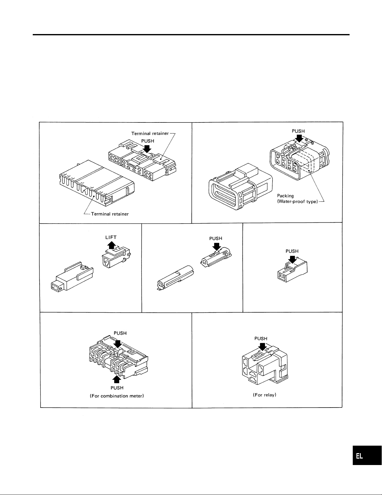
HARNESS CONNECTOR (TAB-LOCKING TYPE)
쐌 The tab-locking type connectors help prevent accidental looseness or disconnection.
쐌 The tab-locking type connectors are disconnected by pushing or lifting the locking tab(s). Refer to the
illustration below.
Refer to EL-6 for description of the slide-locking type connector.
CAUTION:
Do not pull the harness when disconnecting the connector.
[Example]
NGEL0003
NGEL0003S01
GI
MA
EM
LC
EC
FE
CL
MT
AT
TF
PD
AX
SU
BR
ST
RS
BT
EL-5
SEL769D
HA
SC
IDX
Description (Cont’d)
HARNESS CONNECTOR
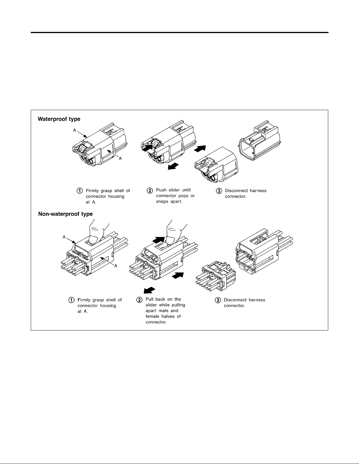
HARNESS CONNECTOR (SLIDE-LOCKING TYPE)
=NGEL0003S02
쐌 A new style slide-locking connector is used on certain systems and components, especially those related
to OBD>
쐌 The slide-locking type connectors help prevent incomplete locking and accidental looseness or disconnec-
tion.
쐌 The slide-locking type connectors are disconnected by pushing or pulling the slider. Refer to the illustra-
tion below.
CAUTION:
Do not pull the harness or wires when disconnecting the connector.
Be careful not to damage the connector support bracket when disconnecting the connector.
EL-6
AEL299C
STANDARDIZED RELAY
Description
Description
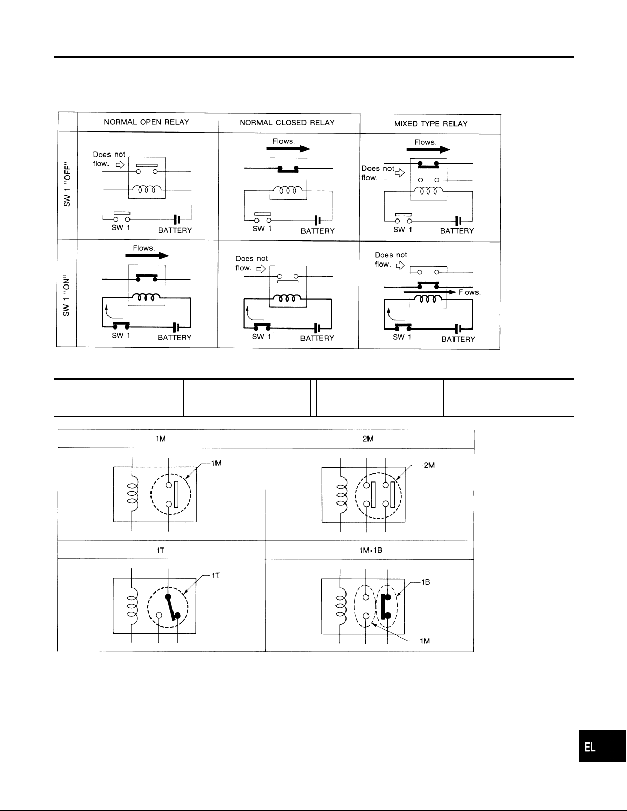
NORMAL OPEN, NORMAL CLOSED AND MIXED TYPE RELAYS
Relays can mainly be divided into three types: normal open, normal closed and mixed type relays.
NGEL0004
NGEL0004S01
SEL881H
GI
MA
EM
LC
EC
FE
CL
MT
TYPE OF STANDARDIZED RELAYS
1M 1 Make 2M 2 Make
1T 1 Transfer 1M·1B 1 Make 1 Break
NGEL0004S02
SEL882H
AT
TF
PD
AX
SU
BR
ST
RS
BT
EL-7
HA
SC
IDX
Description (Cont’d)
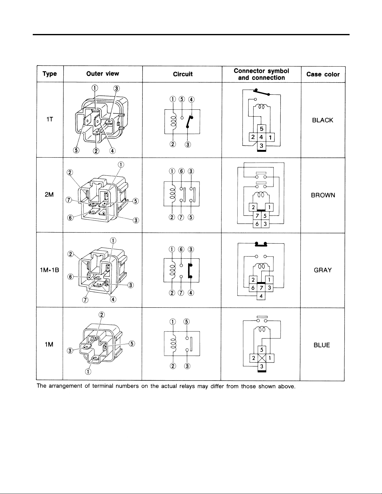
STANDARDIZED RELAY
EL-8
SEL661TA
POWER SUPPLY ROUTING
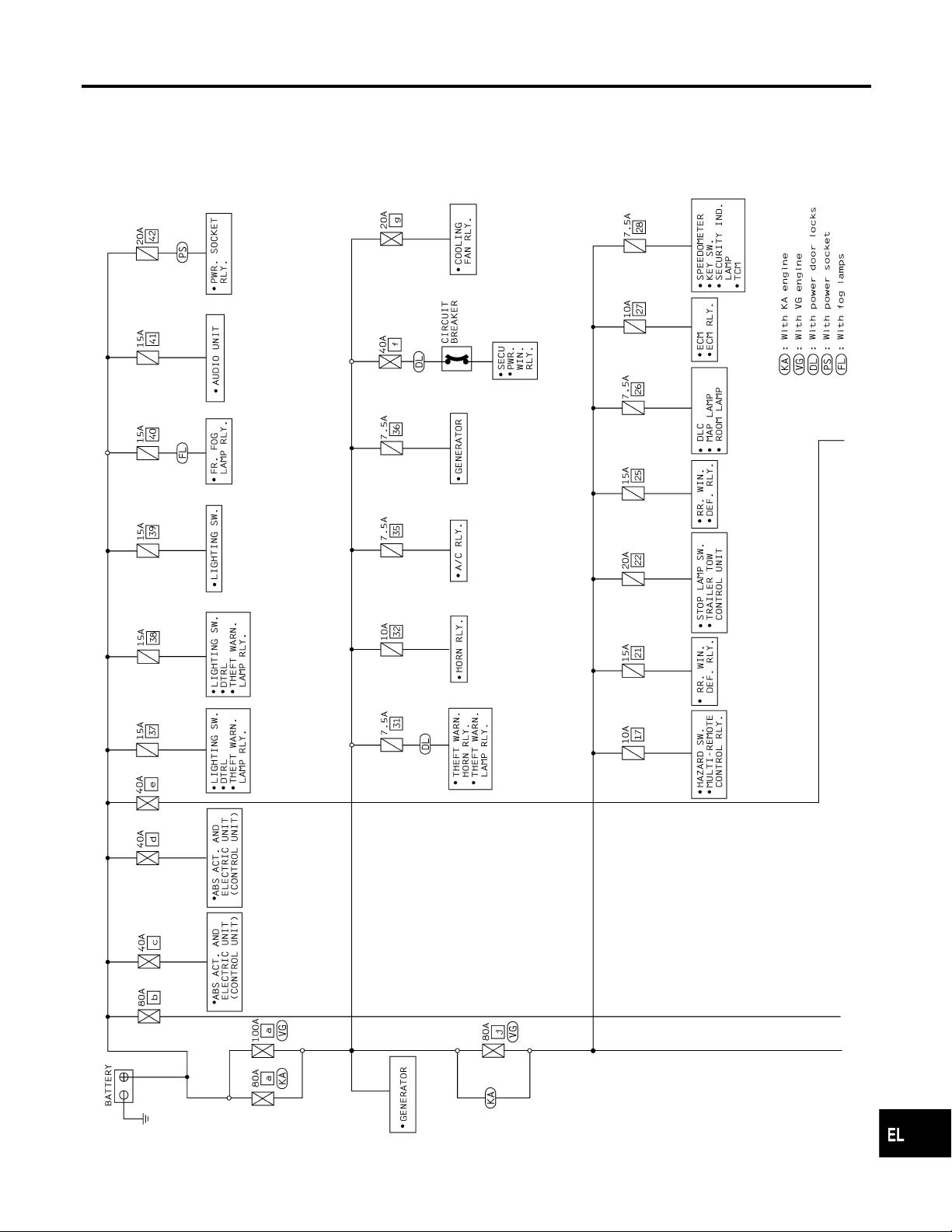
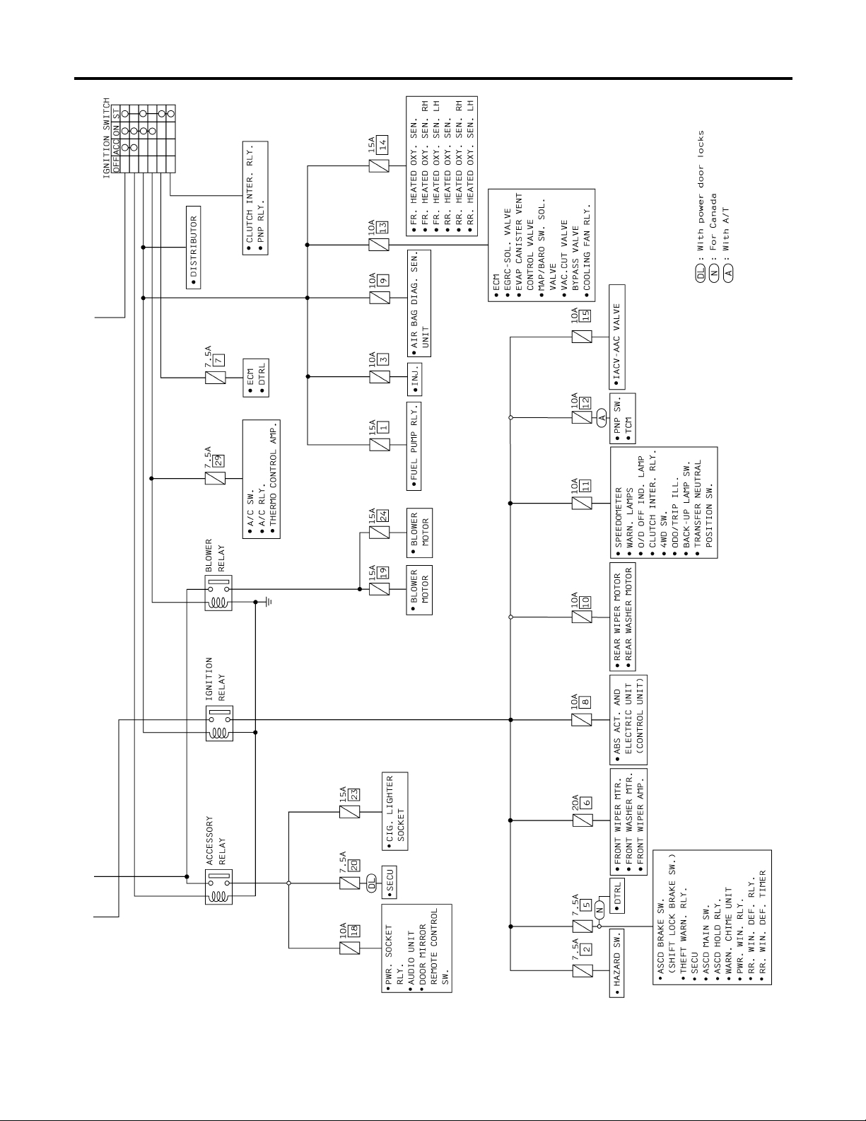
Circuit Diagram
Circuit Diagram
NOTE:
For detailed ground distribution information, refer to “GROUND DISTRIBUTION”, EL-17.
NGEL0005
GI
MA
EM
LC
EC
FE
CL
MT
AT
TF
PD
AX
SU
BR
ST
RS
BT
EL-9
AEL409C
HA
SC
IDX
Circuit Diagram (Cont’d)
POWER SUPPLY ROUTING
EL-10
AEL410C

POWER SUPPLY ROUTING
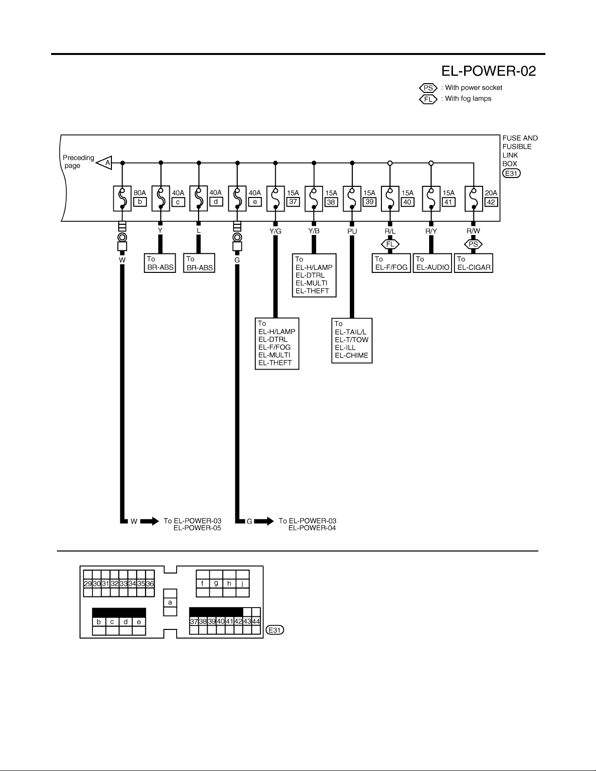
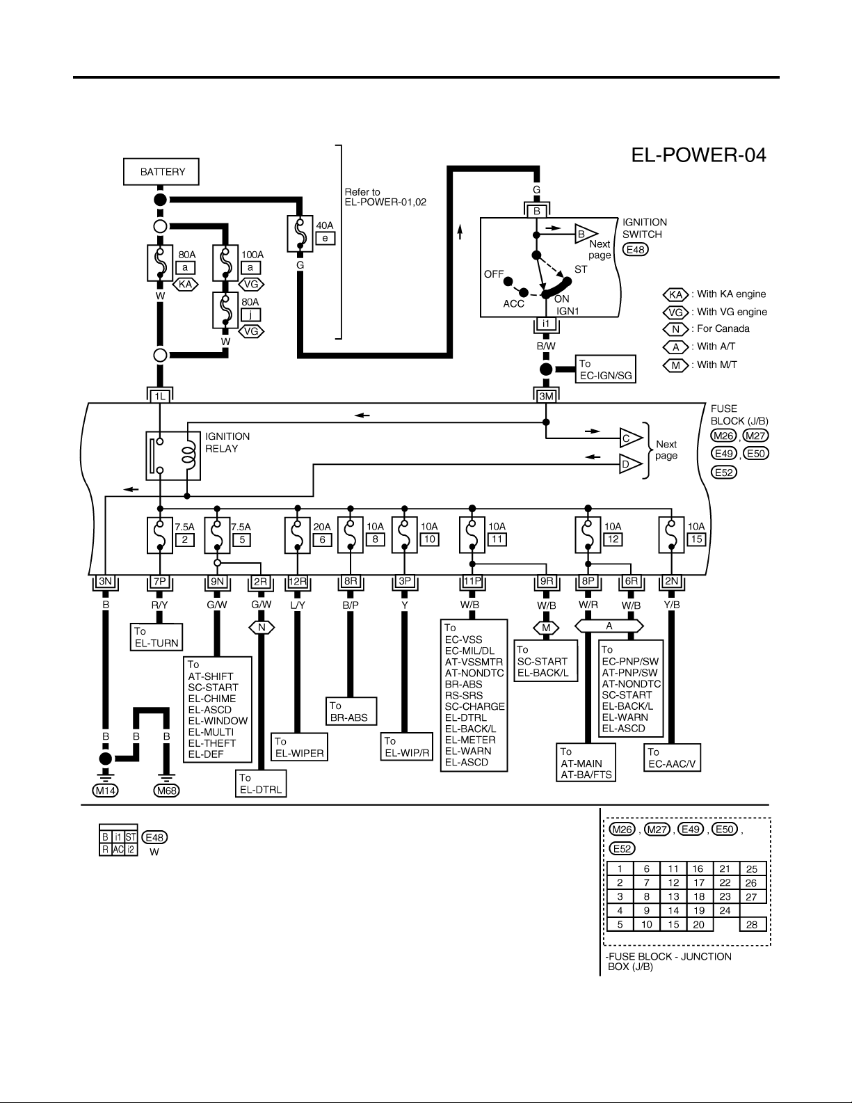
Wiring Diagram — POWER —
Wiring Diagram — POWER —
BATTERY POWER SUPPLY — IGNITION SW. IN ANY POSITION
NOTE:
For detailed ground distribution information, refer to “GROUND DISTRIBUTION”, EL-17.
=NGEL0006
NGEL0006S01
GI
MA
EM
LC
EC
FE
CL
MT
AT
TF
PD
AX
SU
BR
ST
RS
BT
EL-11
HA
SC
AEL411C
IDX
Wiring Diagram — POWER — (Cont’d)
POWER SUPPLY ROUTING
EL-12
AEL412C
POWER SUPPLY ROUTING
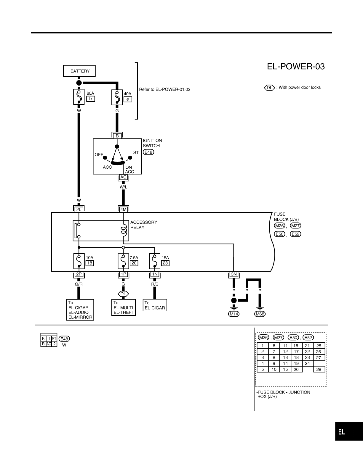
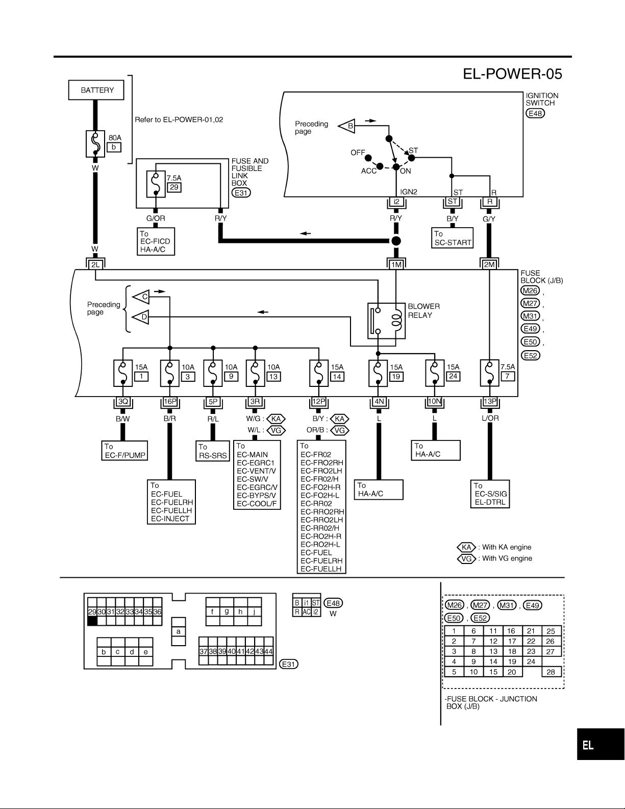
Wiring Diagram — POWER — (Cont’d)
ACCESSORY POWER SUPPLY — IGNITION SW. IN ACC OR ON
NOTE:
For detailed ground distribution information, refer to “GROUND DISTRIBUTION”, EL-17.
=NGEL0006S02
GI
MA
EM
LC
EC
FE
CL
MT
AT
TF
PD
AX
SU
BR
ST
RS
BT
EL-13
AEL413C
HA
SC
IDX
Wiring Diagram — POWER — (Cont’d)
POWER SUPPLY ROUTING
IGNITION POWER SUPPLY — IGNITION SW. IN ON AND/OR START
NOTE:
For detailed ground distribution information, refer to “GROUND DISTRIBUTION”, EL-17.
=NGEL0006S03
EL-14
AEL414C
POWER SUPPLY ROUTING
Wiring Diagram — POWER — (Cont’d)
GI
MA
EM
LC
EC
FE
CL
MT
AT
TF
PD
AX
SU
BR
ST
RS
EL-15
BT
HA
SC
AEL415C
IDX
Inspection
POWER SUPPLY ROUTING
CEL083
MEL944F
Inspection
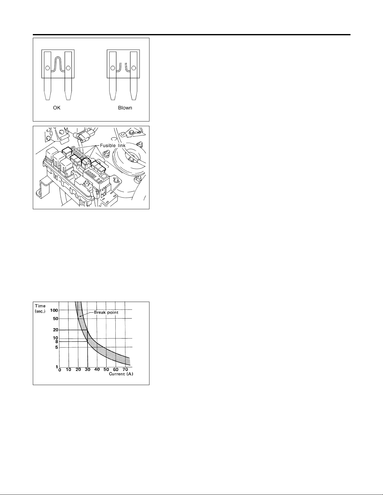
FUSE
NGEL0007
NGEL0007S01
쐌 If fuse is blown, be sure to eliminate cause of problem
before installing new fuse.
쐌 Use fuse of specified rating. Never use fuse of more than
specified rating.
쐌 Do not partially install fuse; always insert it into fuse
holder properly.
쐌 Remove fuse for “ELECTRICAL PARTS (BAT)” if vehicle is
not used for a long period of time.
FUSIBLE LINK
NGEL0007S02
A melted fusible link can be detected either by visual inspection or
by feeling with finger tip. If its condition is questionable, use circuit
tester or test lamp.
CAUTION:
쐌 If fusible link should melt, it is possible that critical circuit
(power supply or large current carrying circuit) is shorted.
In such a case, carefully check and eliminate cause of
problem.
쐌 Never wrap outside of fusible link with vinyl tape. Impor-
tant: Never let fusible link touch any other wiring harness,
vinyl or rubber parts.
SBF284E
CIRCUIT BREAKER
NGEL0007S03
For example, when current is 30A, the circuit is broken within 8 to
20 seconds.
Circuit breakers are used in the following systems.
EL-16
GROUND
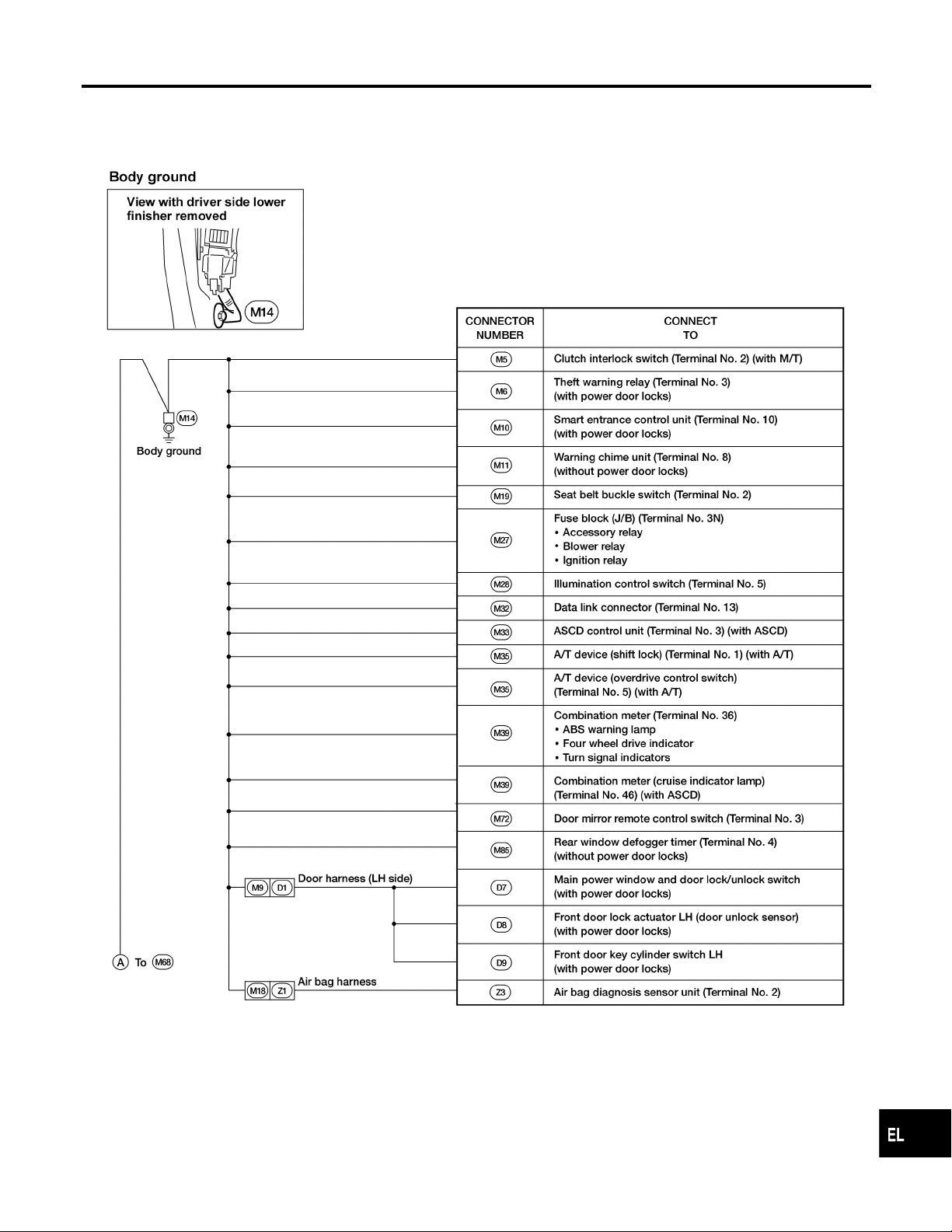
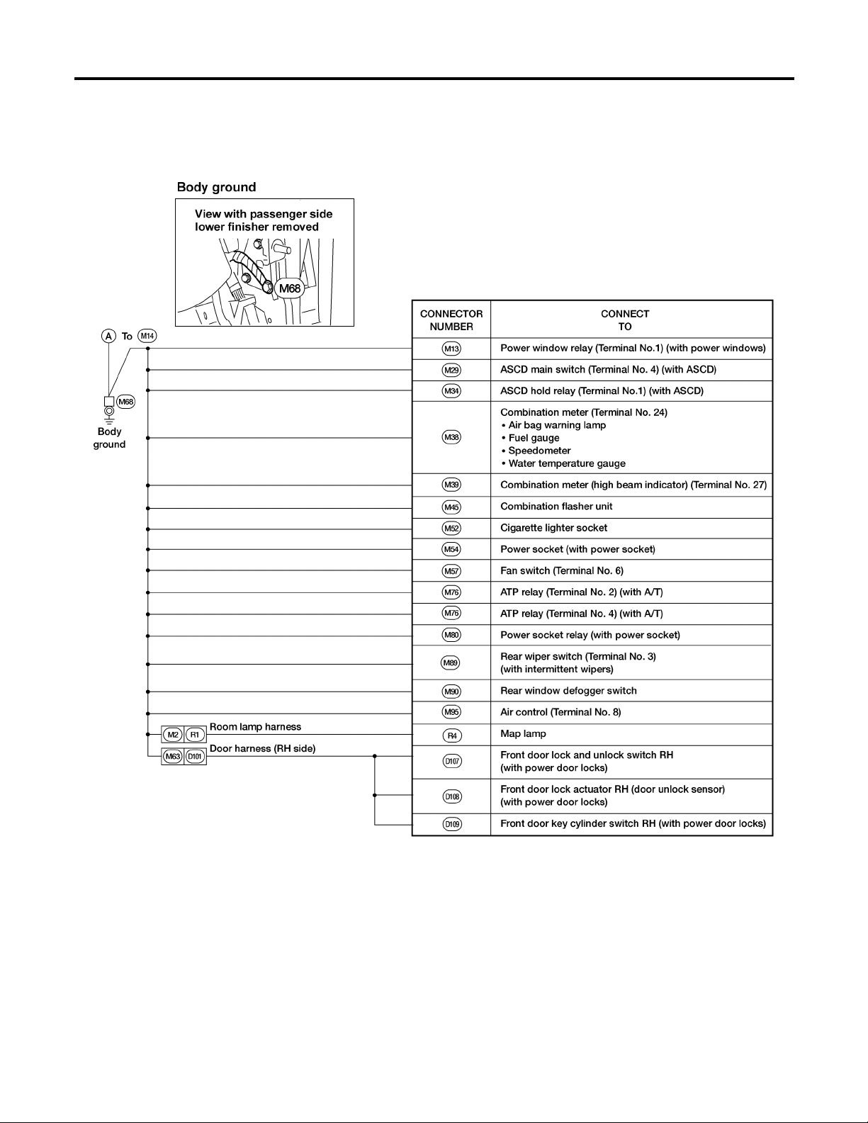
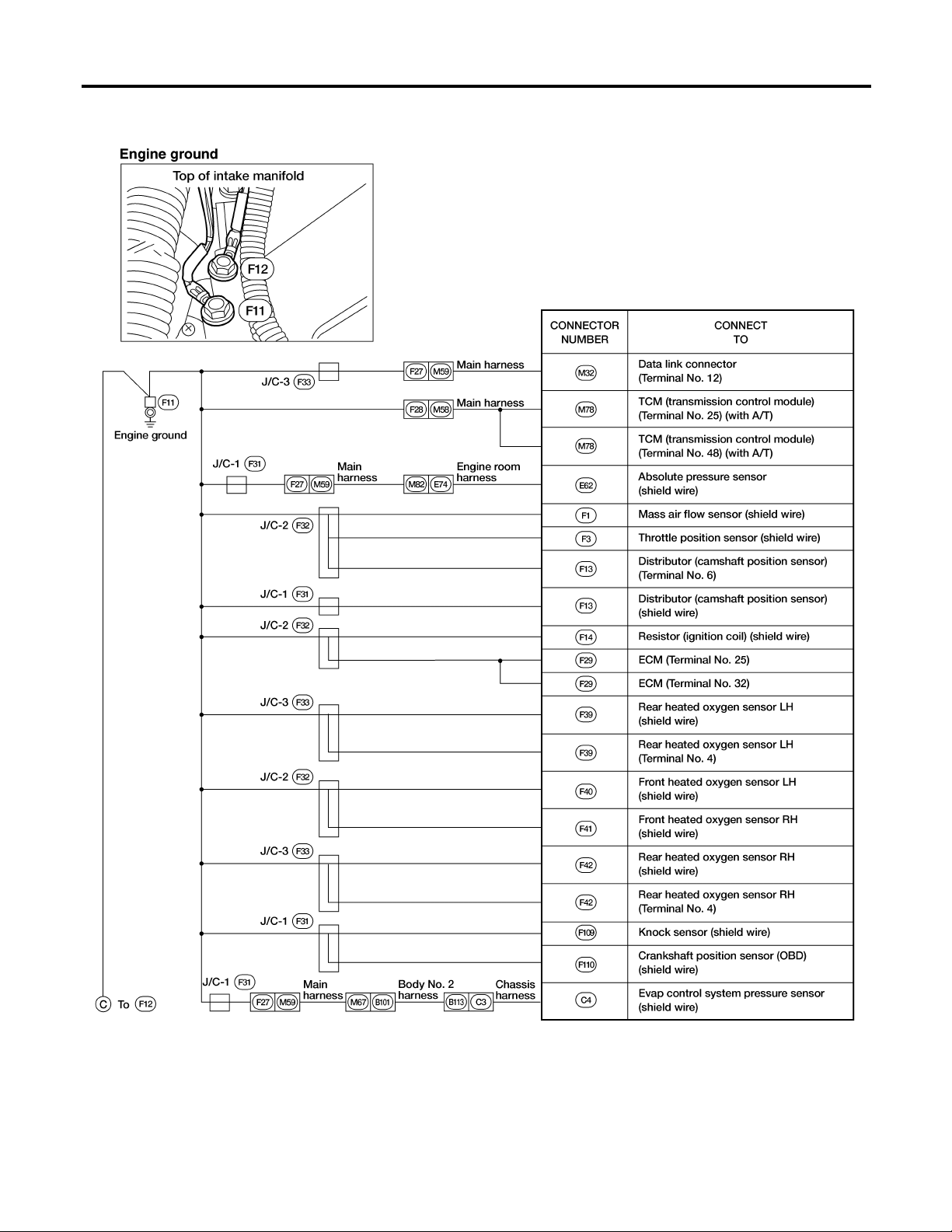
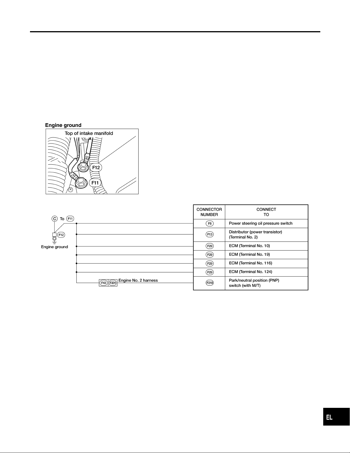
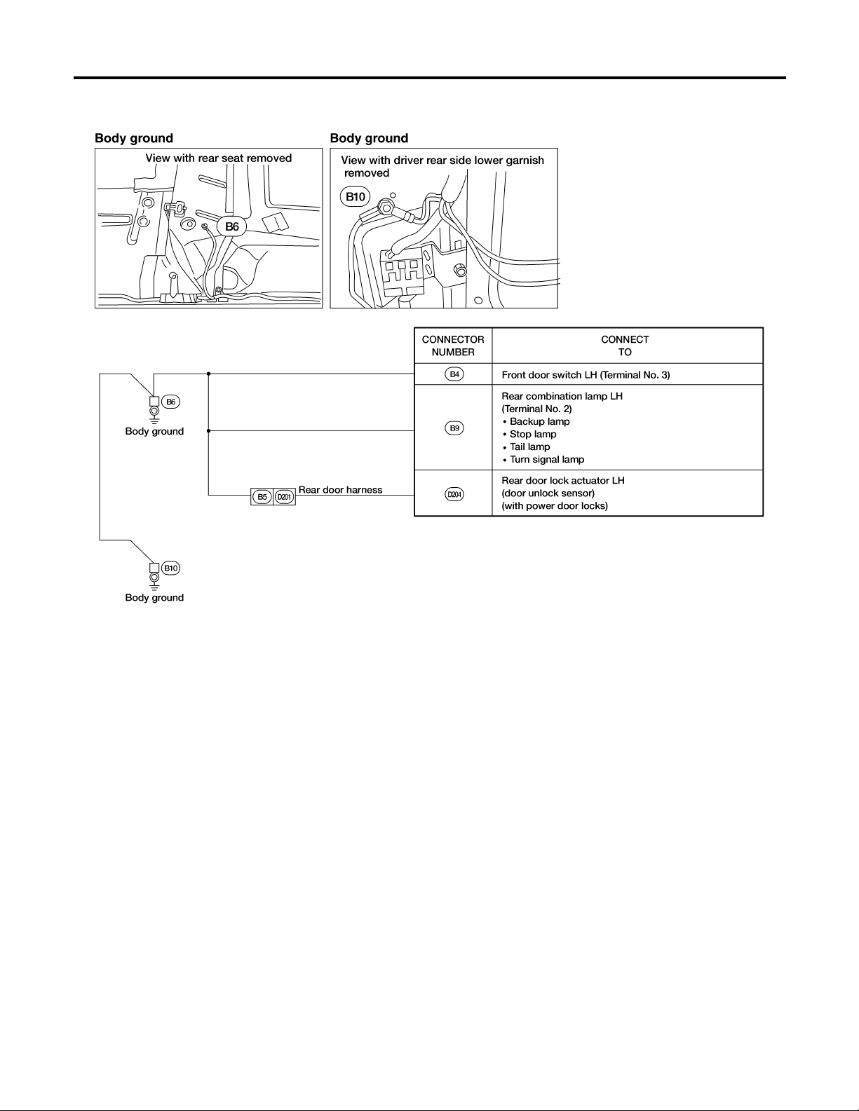
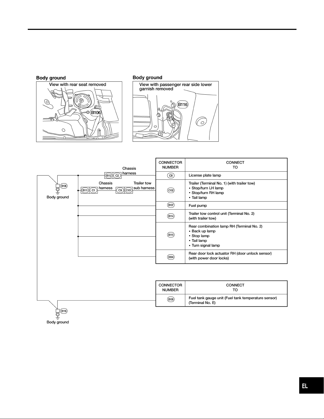
Ground Distribution
Ground Distribution
MAIN HARNESS
NGEL0171
NGEL0171S01
GI
MA
EM
LC
EC
FE
CL
MT
AT
TF
PD
AX
SU
BR
ST
RS
BT
EL-17
AEL706C
HA
SC
IDX
Ground Distribution (Cont’d)
GROUND
EL-18
AEL707C
GROUND
Ground Distribution (Cont’d)
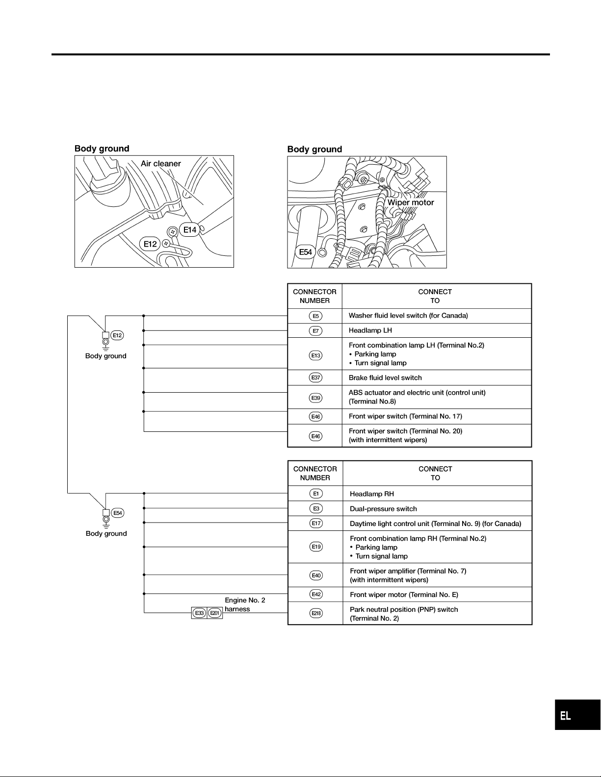
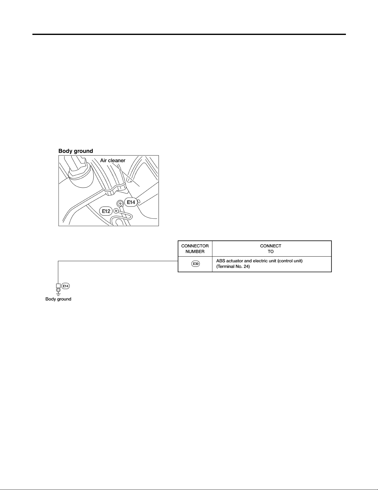
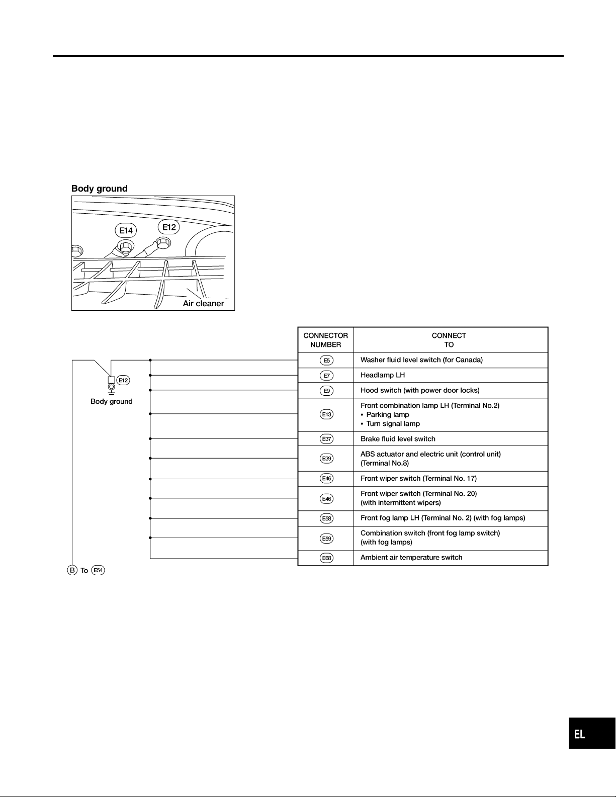
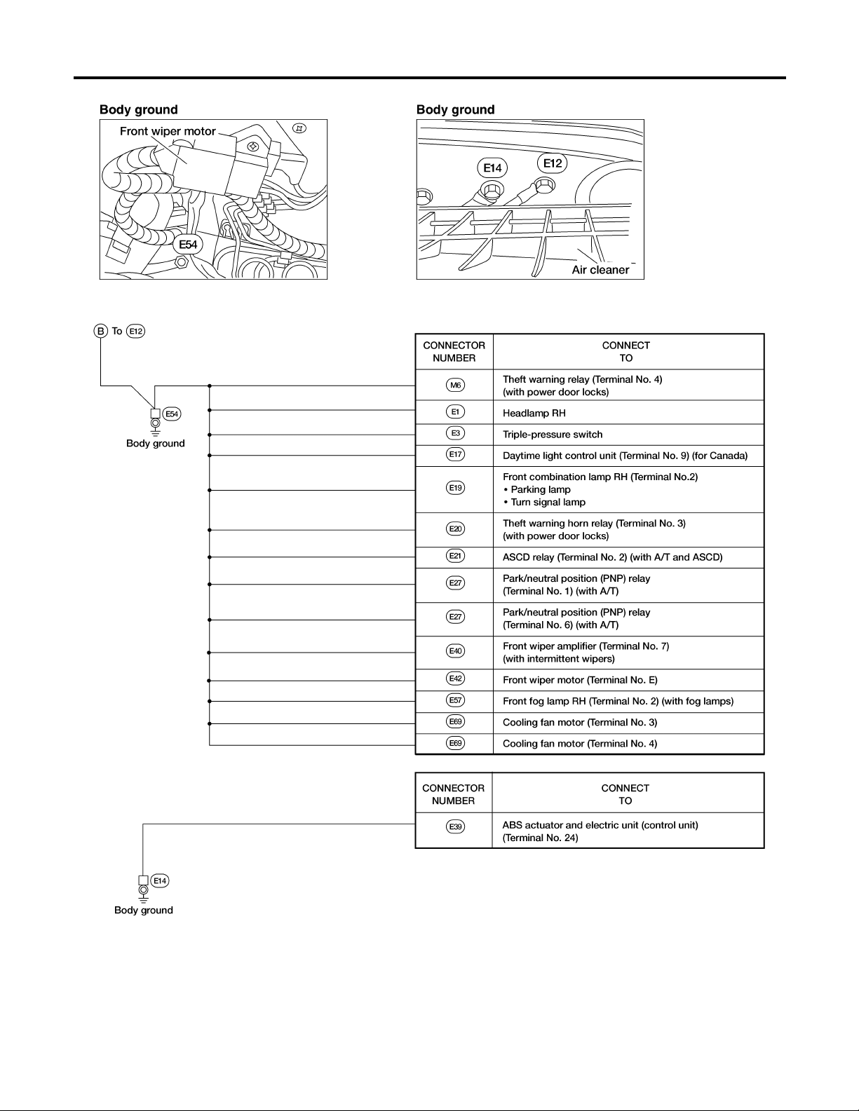
ENGINE ROOM HARNESS
KA24DE
NGEL0171S02
NGEL0171S0201
GI
MA
EM
LC
EC
FE
CL
MT
AT
TF
PD
AX
SU
BR
ST
RS
BT
EL-19
HA
AEL708C
SC
IDX
Ground Distribution (Cont’d)
GROUND
EL-20
AEL709C
GROUND
Ground Distribution (Cont’d)
VG33E
NGEL0171S0202
GI
MA
EM
LC
EC
FE
CL
MT
AT
TF
PD
AX
SU
BR
ST
RS
BT
EL-21
AEL711C
HA
SC
IDX
Ground Distribution (Cont’d)
GROUND
EL-22
AEL712C
GROUND
Ground Distribution (Cont’d)
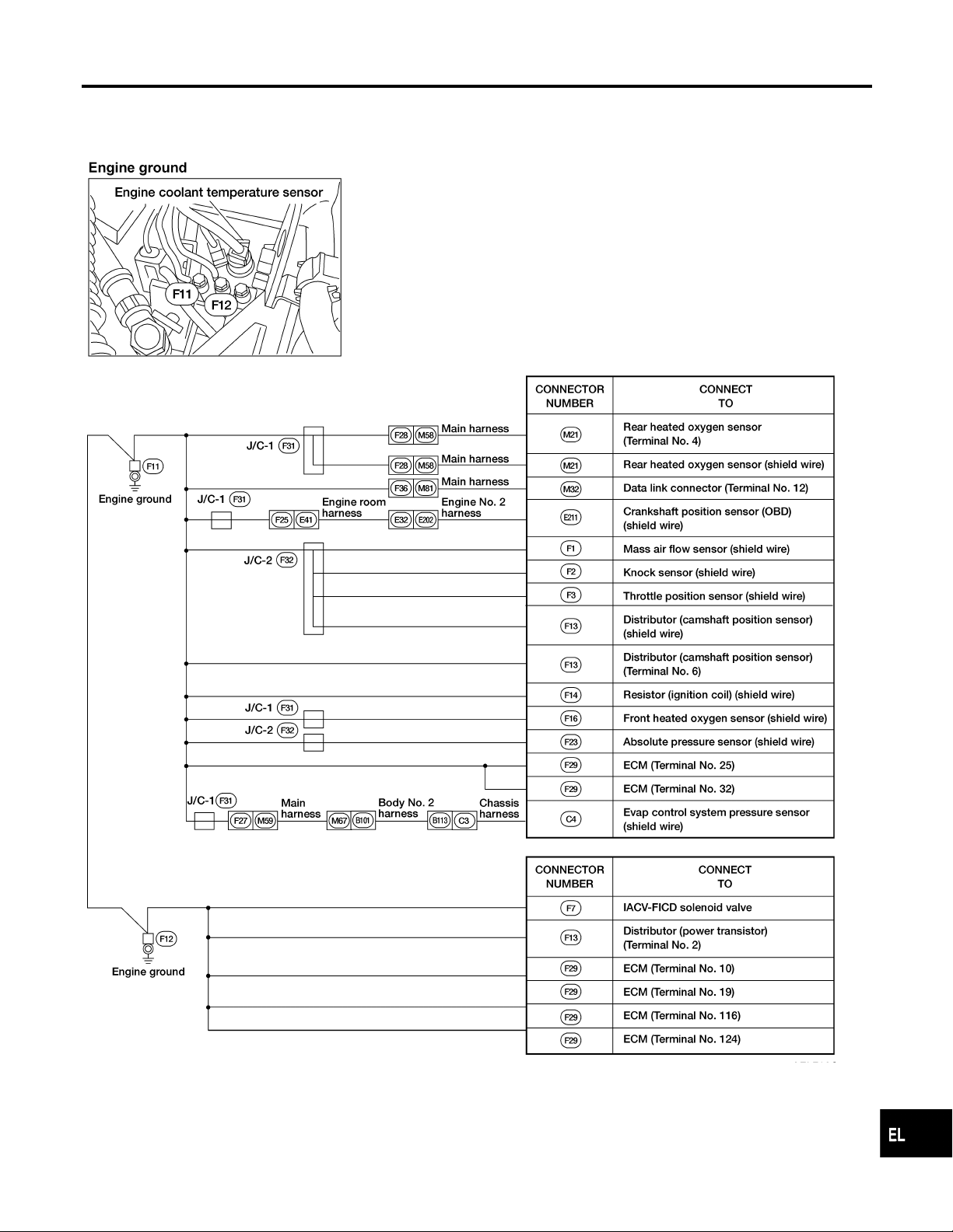
ENGINE NO. 2 HARNESS
KA24DE
NGEL0171S08
NGEL0171S0801
GI
MA
EM
LC
EC
FE
CL
MT
AEL710C
AT
TF
PD
AX
SU
BR
ST
RS
BT
EL-23
HA
SC
IDX
Ground Distribution (Cont’d)
GROUND
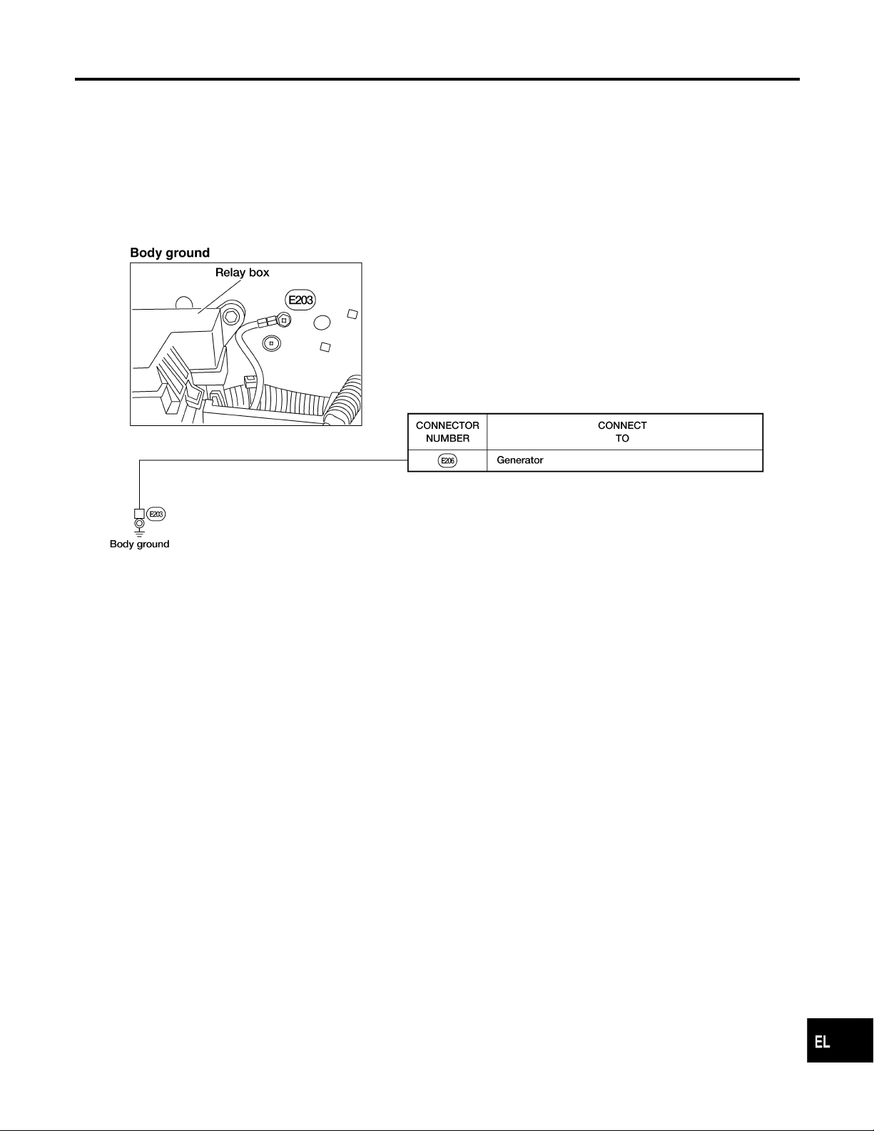
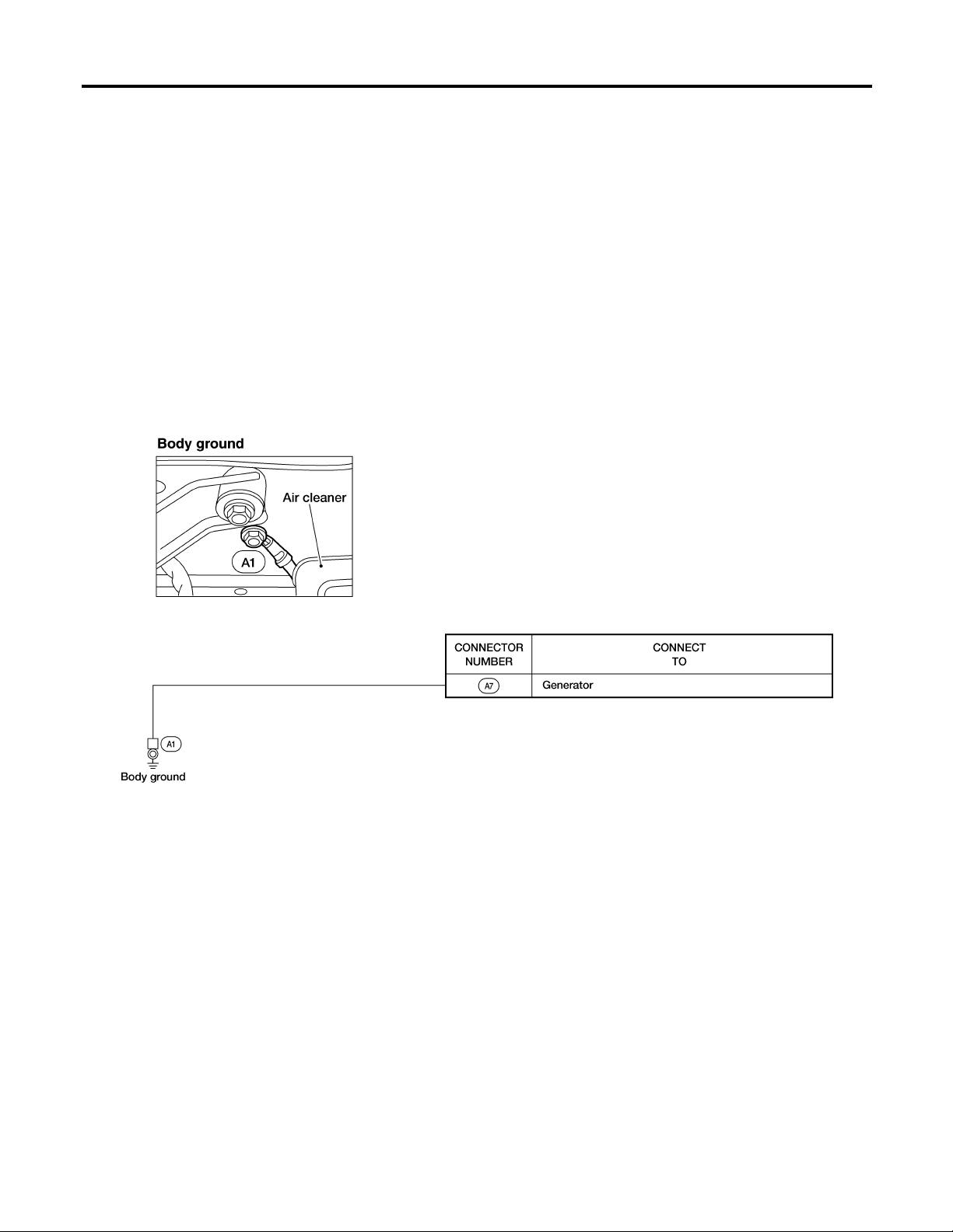
GENERATOR HARNESS
VG33E
NGEL0171S03
NGEL0171S0301
EL-24
AEL697C
GROUND
Ground Distribution (Cont’d)
ENGINE CONTROL HARNESS
KA24DE
NGEL0171S04
NGEL0171S0401
GI
MA
EM
LC
EC
FE
CL
MT
AT
TF
PD
AX
SU
BR
ST
RS
BT
EL-25
HA
AEL713C
SC
IDX
Ground Distribution (Cont’d)
GROUND
VG33E
NGEL0171S0402
EL-26
AEL714C
GROUND
Ground Distribution (Cont’d)
GI
MA
EM
LC
EC
FE
CL
MT
AT
TF
PD
AX
SU
BR
ST
RS
EL-27
AEL715C
BT
HA
SC
IDX
Ground Distribution (Cont’d)
GROUND
BODY HARNESS
NGEL0171S05
AEL716C
EL-28
GROUND
Ground Distribution (Cont’d)
BODY NO. 2 HARNESS
NGEL0171S06
GI
MA
EM
LC
EC
FE
CL
MT
AT
TF
PD
AX
SU
BR
ST
RS
BT
EL-29
AEL717C
HA
SC
IDX
Ground Distribution (Cont’d)
GROUND
BACK DOOR NO. 2 HARNESS
NGEL0171S07
AEL718C
EL-30

COMBINATION SWITCH
Check
Check
NGEL0009
GI
MA
EM
LC
EC
FE
CL
MT
AT
TF
PD
AX
SU
BR
ST
RS
BT
EL-31
HA
SC
AEL122C
IDX

Replacement
COMBINATION SWITCH
SEL865L
MEL205B
Replacement
NGEL0010
For removal and installation of spiral cable, refer to RS-16,
[“Driver Air Bag Module and Spiral Cable”, “SUPPLEMENTAL
RESTRAINT SYSTEM (SRS)”].
쐌 Each switch can be replaced without removing combination
switch base.
쐌 To remove combination switch base, remove base attaching
screws.
쐌 Before installing the steering wheel, align the turn signal can-
cel tab with the notch of the combination switch. Refer to RS
RS-16,[“Driver Air Bag Module and Spiral Cable”, “SUPPLE-
MENTAL RESTRAINT SYSTEM (SRS)”].
ARS152
EL-32

STEERING SWITCH
Check
Check
NGEL0011
GI
MA
EM
LC
EC
FE
CL
MT
AT
TF
PD
AX
SU
BR
ST
RS
BT
EL-33
HA
SC
AEL603B
IDX

System Description
HEADLAMP (FOR USA)
System Description
NGEL0012
The headlamps are controlled by the lighting switch which is built into the combination switch.
Power is supplied at all times
쐌 through 15A fuse (No. 37, located in the fuse and fusible link box)
쐌 to lighting switch terminal 5 and
쐌 through 15A fuse (No. 38, located in the fuse and fusible link box)
쐌 to lighting switch terminal 8.
LOW BEAM OPERATION
NGEL0012S01
With the lighting switch in the headlamp ON (2ND) position and LOW BEAM (B) position, power is supplied
쐌 from lighting switch terminal 10
쐌 to headlamp LH terminal D and
쐌 from lighting switch terminal 7
쐌 to headlamp RH terminal D.
Ground is supplied to headlamp LH/RH terminal E through body grounds E12 and E54.
With power and ground supplied, the low beams illuminate.
HIGH BEAM OPERATION/FLASH-TO-PASS OPERATION
NGEL0012S02
With the lighting switch in the FLASH TO PASS (C) position or the headlamp ON (2ND) position and HIGH
BEAM (A) position, power is supplied
쐌 from lighting switch terminal 6
쐌 to headlamp RH terminal M and
쐌 from lighting switch terminal 9
쐌 to headlamp LH terminal M and
쐌 to combination meter terminal 26 for the high beam indicator.
Ground is supplied to terminal 27 of the combination meter through body grounds M14 and M68.
Ground is supplied to headlamp LH/RH terminal E through body grounds E12 and E54.
With power and ground supplied, the high beams and the high beam indicator illuminate.
THEFT WARNING SYSTEM
NGEL0012S03
The theft warning system will flash the high beams if the system is triggered. Refer to “System Description”,
“THEFT WARNING SYSTEM”, EL-227.
EL-34

HEADLAMP (FOR USA)
Wiring Diagram — H/LAMP —
Wiring Diagram — H/LAMP —
NGEL0013
GI
MA
EM
LC
EC
FE
CL
MT
AT
TF
PD
AX
SU
BR
ST
RS
BT
EL-35
HA
SC
AEL347C
IDX

Trouble Diagnoses
HEADLAMP (FOR USA)
Symptom Possible cause Repair order
Neither headlamp LH nor headlamp
RH operate.
Headlamp LH does not operate,
but headlamp RH operates properly.
Headlamp RH does not operate,
but headlamp LH operates properly.
High beam LH does not operate,
but low beam LH operates.
Low beam LH does not operate,
but high beam LH operates.
Trouble Diagnoses
1. Lighting switch 1. Check lighting switch.
1. Bulb
2. Headlamp LH ground circuit
3. 15A fuse
4. Lighting switch
1. Bulb
2. Headlamp RH ground circuit
3. 15A fuse
4. Lighting switch
1. Bulb
2. Open in high beam LH circuit
3. Lighting switch
1. Bulb
2. Open in low beam LH circuit
3. Lighting switch
1. Check bulb.
2. Check continuity between headlamp LH terminal E
and grounds E12 and E54.
3. Check 15A fuse (No. 38, located in fuse and fusible
link box). Verify battery positive voltage is present at
terminal 8 of lighting switch.
4. Check lighting switch.
1. Check bulb.
2. Check continuity between headlamp RH terminal E
and grounds E12 and E54.
3. Check 15A fuse (No. 37, located in fuse and fusible
link box). Verify battery positive voltage is present at
terminal 5 of lighting switch.
4. Check lighting switch.
1. Check bulb.
2. Check R/G wire between lighting switch and headlamp LH for an open circuit.
3. Check lighting switch.
1. Check bulb.
2. Check R wire between lighting switch and headlamp LH for an open circuit.
3. Check lighting switch.
NGEL0014
High beam RH does not operate,
but low beam RH operates.
Low beam RH does not operate,
but high beam RH operates.
High beam indicator does not work. 1. Bulb
1. Bulb
2. Open in high beam RH circuit
3. Lighting switch
1. Bulb
2. Open in low beam RH circuit
3. Lighting switch
2. High beam indicator ground circuit
3. Open in high beam circuit
1. Check bulb.
2. Check R/W wire between lighting switch and headlamp RH for an open circuit.
3. Check lighting switch.
1. Check bulb.
2. Check R/B wire between lighting switch and headlamp RH for an open circuit.
3. Check lighting switch.
1. Check bulb in combination meter.
2. Check continuity between combination meter terminal 27 and grounds M14 and M68.
3. Check R/G wire between lighting switch and combination meter for an open circuit.
EL-36

HEADLAMP (FOR USA)
Bulb Replacement
AEL722C
Bulb Replacement
The headlamp is a semi-sealed beam type which uses a replaceable halogen bulb. The bulb can be replaced from the engine compartment side without removing the headlamp body.
쐌 Grasp only the plastic base when handling the bulb. Never
touch the glass envelope.
1. Disconnect the battery cable.
2. Disconnect the harness connector from the back side of the
bulb.
3. Unclip the bulb retaining clip, and then remove it.
4. Remove the headlamp bulb carefully. Do not shake or rotate
the bulb when removing it.
5. Install in the reverse order of removal.
CAUTION:
Do not leave headlamp reflector without bulb for a long period
of time. Dust, moisture, smoke, etc. entering headlamp body
may affect the performance of the headlamp. Remove headlamp bulb from the headlamp reflector just before a replacement bulb is installed.
=NGEL0015
GI
MA
EM
LC
EC
FE
CL
MT
AT
TF
PD
AX
SU
BR
ST
RS
BT
EL-37
HA
SC
IDX

Aiming Adjustment
HEADLAMP (FOR USA)
Aiming Adjustment
=NGEL0016
When performing headlamp aiming adjustment, use an aiming
machine, aiming wall screen or headlamp tester.Aimers should be
in good repair, calibrated and operated in accordance with respective operation manuals.
If any aimer is not available, aiming adjustment can be done as
follows:
For details, refer to the regulations in your own country.
1) Keep all tires inflated to correct pressures.
2) Place vehicle and tester on one and same flat surface.
3) See that there is no-load in vehicle (coolant, engine oil
filled up to correct level and full fuel tank) other than the
driver (or equivalent weight placed in driver’s position).
AIMER ADJUSTMENT MARK
NGEL0016S01
When using a mechanical aimer, adjust adapter legs to the data
marked on the headlamps.
Adjustment value for mechanical aimer
AEL615C
AEL671B
Mechanical aimer level
Horizontal side −4 to 4
Vertical side −4 to 4
LOW BEAM
NGEL0016S02
1. Turn headlamp low beam on.
2. Use a #2 cross-recessed screwdriver to adjust the aim of the
lamp.
쐌 Cover the opposite lamp.
EL-38

HEADLAMP (FOR USA)
Aiming Adjustment (Cont’d)
If the vehicle front body has been repaired and/or the headlamp
assembly has been replaced, check aiming. Use the aiming chart
shown in the figure.
쐌 Upper edge and left edge of high intensity zone should be
within the range shown at left. Adjust headlamps accordingly.
쐌 Dotted lines in illustration show center of headlamp.
“H”: Horizontal center line of headlamps
“W
”: Distance between each headlamp center
L
GI
MA
EM
LC
EC
FE
CL
SEL866L
MT
AT
TF
PD
AX
SU
BR
ST
RS
EL-39
BT
HA
SC
IDX

HEADLAMP (FOR CANADA) — DAYTIME LIGHT SYSTEM —
System Description (For Canada)
System Description (For Canada)
NGEL0017
The headlamp system for Canada vehicles contains a daytime light control unit that activates the high beam
headlamps at approximately half illumination whenever the engine is running. If the parking brake is applied
before the engine is started the daytime lights will not be illuminated. The daytime lights will illuminate once
the parking brake is released. Thereafter, the daytime lights will continue to operate when the parking brake
is applied. If the daytime light control unit receives a ground signal from the generator, the daytime lights will
not be illuminated. The daytime lights will illuminate once a battery positive voltage signal is sent to the daytime light control unit from the generator.
Power is supplied at all times
쐌 through 15A fuse (No. 38, located in the fuse and fusible link box)
쐌 to daytime light control unit terminal 3 and
쐌 to lighting switch terminal 8.
Power is also supplied at all times
쐌 through 15A fuse (No. 37, located in the fuse and fusible link box)
쐌 to daytime light control unit terminal 2 and
쐌 to lighting switch terminal 5.
With the ignition switch in the ON or START position, power is supplied
쐌 through 7.5A fuse [No. 5, located in the fuse block (J/B)]
쐌 to daytime light control unit terminal 12.
With the ignition switch in the START position, power is supplied
쐌 through 7.5A fuse [No. 7, located in the fuse block (J/B)]
쐌 to daytime light control unit terminal 1.
Ground is supplied to daytime light control unit terminal 9 through body grounds E12 and E54.
HEADLAMP OPERATION
Low Beam Operation
NGEL0017S01
NGEL0017S0101
When the lighting switch is turned to the headlamp ON (2ND) position, LOW BEAM (B), power is supplied
쐌 from lighting switch terminal 7
쐌 to headlamp RH terminal D and
쐌 to daytime light control unit terminal 4.
Ground is supplied to headlamp RH terminal E through body grounds E12 and E54.
Also, when the lighting switch is turned to the headlamp ON (2ND) position, LOW BEAM (B), power is supplied
쐌 from lighting switch terminal 10
쐌 to headlamp LH terminal D.
Ground is supplied
쐌 to headlamp LH terminal E
쐌 from daytime light control unit terminal 7
쐌 through daytime light control unit terminal 9
쐌 through body grounds E12 and E54.
With power and ground supplied, the low beam headlamps illuminate.
High Beam Operation/Flash-to-pass Operation
NGEL0017S0102
When the lighting switch is turned to the headlamp ON (2ND) position, HIGH BEAM (A) or FLASH TO PASS
(C) position, power is supplied
쐌 from lighting switch terminal 6
쐌 to headlamp RH terminal M and
쐌 to daytime light control unit terminal 8.
Also, when the lighting switch is turned to the headlamp ON (2ND) position, HIGH BEAM (A) or FLASH TO
PASS (C) position, power is supplied
쐌 from lighting switch terminal 9
쐌 to combination meter terminal 26 for the high beam indicator and
쐌 to daytime light control unit terminal 5
쐌 through daytime light control unit terminal 6
EL-40

HEADLAMP (FOR CANADA) — DAYTIME LIGHT SYSTEM —
System Description (For Canada) (Cont’d)
쐌 to headlamp LH terminal M.
Ground is supplied in the same manner as low beam operation.
Ground is supplied to combination meter terminal 27 through body grounds M14 and M68.
With power and ground supplied, the high beam headlamps and HI BEAM indicator illuminate.
GI
DAYTIME LIGHT OPERATION
With the engine running, the lighting switch in the OFF or 1ST position and parking brake released, power is
supplied
쐌 to daytime light control unit terminal 3
쐌 through daytime light control unit terminal 6
쐌 to headlamp LH terminal M
쐌 through headlamp LH terminal E
쐌 to daytime light control unit terminal 7
쐌 through daytime light control unit terminal 8
쐌 to headlamp RH terminal M.
Ground is supplied to headlamp RH terminal E through body grounds E12 and E54.
Because the high beam headlamps are now wired in series, they operate at half illumination.
OPERATION (FOR CANADA)
After starting the engine with the lighting switch in the OFF or parking lamp (1ST) position, the headlamp high
beams automatically turn on. Lighting switch operations other than the above are the same as conventional
light systems.
Engine With engine stopped With engine running
OFF 1ST 2ND OFF 1ST 2ND
Lighting switch
ABCABCABCABCABCABC
High beam X X O X X O O X O 왕* 왕*O왕* 왕*O O X O
Headlamp
Low beam XXXXXXXOXXXXXXXXOX
Clearance and tail lamp X X X OOOOOOXXXOOOOOO
NGEL0017S02
NGEL0017S03
MA
EM
LC
EC
FE
CL
MT
AT
TF
PD
License and instrument illumination
lamp
A: HIGH BEAM position
B: LOW BEAM position
C: FLASH TO PASS position
O : Lamp ON
X : Lamp OFF
왕 : Lamp dims. (Added functions)
*: When starting the engine with the parking brake released, the daytime lights will come ON.
When starting the engine with the parking brake pulled, the daytime lights won’t come ON.
XXXOOOOOOXXXOOOOOO
AX
SU
BR
ST
RS
BT
HA
SC
EL-41
IDX

Circuit Diagram
HEADLAMP (FOR CANADA) — DAYTIME LIGHT SYSTEM —
Circuit Diagram
NGEL0019
AEL348C
EL-42

HEADLAMP (FOR CANADA) — DAYTIME LIGHT SYSTEM —
Wiring Diagram — DTRL —
Wiring Diagram — DTRL —
NGEL0020
GI
MA
EM
LC
EC
FE
CL
MT
AT
TF
PD
AX
SU
BR
ST
RS
BT
EL-43
HA
SC
AEL349C
IDX

HEADLAMP (FOR CANADA) — DAYTIME LIGHT SYSTEM —
Wiring Diagram — DTRL — (Cont’d)
EL-44
AEL350C

HEADLAMP (FOR CANADA) — DAYTIME LIGHT SYSTEM —
Wiring Diagram — DTRL — (Cont’d)
GI
MA
EM
LC
EC
FE
CL
MT
AT
TF
PD
AX
SU
BR
ST
RS
EL-45
BT
HA
SC
AEL351C
IDX

HEADLAMP (FOR CANADA) — DAYTIME LIGHT SYSTEM —
Trouble Diagnoses
Trouble Diagnoses
DAYTIME LIGHT CONTROL UNIT INSPECTION TABLE
Terminal
No.
1 L/OR Ignition switch start signal Ignition switch in START position 12
2 Y/G Power source for head-
3 Y/B Power source for head-
4 R/B Lighting switch headlamp
5 R/G Lighting switch headlamp
6 R/Y Headlamp LH high beam Lighting switch in the FLASH TO PASS (C) position
Wire
color
Item Condition
lamp RH
lamp LH
RH low beam output
LH high beam output
(Approximate value)
All other conditions 0
— 12
— 12
Lighting switch in the headlamp ON (2ND) position
and LOW BEAM (B) position
All other conditions 0
Lighting switch in the FLASH TO PASS (C) position
or headlamp ON (2ND) position and HIGH BEAM (A)
position
All other conditions 0
or headlamp ON (2ND) position and HIGH BEAM (A)
position
NGEL0021
NGEL0021S01
Voltage
12
12
12
With parking brake released, engine running and
lighting switch in OFF or parking and tail lamp ON
(1ST) positions
CAUTION:
Block wheels and ensure selector lever is in P or
N position.
All other conditions 0
7 B/W Headlamp LH control
(ground)
8 R/W Lighting switch headlamp
RH high beam output
9 B Ground ——
Lighting switch in the FLASH TO PASS (C) position
or headlamp ON (2ND) position
All other conditions 6
Lighting switch in the FLASH TO PASS (C) position
or headlamp ON (2ND) position and HIGH BEAM (A)
position
With parking brake released, engine running and
lighting switch in OFF or parking and tail lamp ON
(1ST) positions
CAUTION:
Block wheels and ensure selector lever is in P or
N position.
All other conditions 0
12
0
12
6
10 Y Parking brake switch Parking brake released 12
Parking brake set 0
11 Y/B Generator
(L terminal)
When engine is running 12
All other conditions 0
EL-46

HEADLAMP (FOR CANADA) — DAYTIME LIGHT SYSTEM —
Trouble Diagnoses (Cont’d)
12 G/W Ignition switch on signal Ignition switch OFF, ACC positions 0
Ignition switch ON, START positions 12
Bulb Replacement
Refer to “HEADLAMP (FOR USA)”, EL-37.
Aiming Adjustment
Refer to “HEADLAMP (FOR USA)”, EL-38.
NGEL0022
NGEL0023
GI
MA
EM
LC
EC
FE
CL
MT
AT
TF
PD
AX
SU
BR
ST
RS
BT
HA
EL-47
SC
IDX

Wiring Diagram — TAIL/L —
PARKING, LICENSE AND TAIL LAMPS
Wiring Diagram — TAIL/L —
NGEL0024
EL-48
AEL352C

STOP LAMP
Wiring Diagram — STOP/L —
Wiring Diagram — STOP/L —
NGEL0025
GI
MA
EM
LC
EC
FE
CL
MT
AT
TF
PD
AX
SU
BR
ST
RS
BT
EL-49
HA
SC
AEL353C
IDX

Wiring Diagram — BACK/L —
BACK-UP LAMP
Wiring Diagram — BACK/L —
NGEL0026
EL-50
AEL354C

FRONT FOG LAMP
System Description
System Description
Power is supplied at all times
쐌 through 15A fuse (No. 40, located in the fuse and fusible link box)
쐌 to front fog lamp relay terminal 5 and
쐌 through 15A fuse (No. 37, located in the fuse and fusible link box)
쐌 to lighting switch terminal 5.
With the lighting switch in the headlamp ON (2ND) position and LOW BEAM (B) position, power is supplied
쐌 through lighting switch terminal 7
쐌 to front fog lamp relay terminal 2.
FRONT FOG LAMP OPERATION
The front fog lamp switch is built into the combination switch. The lighting switch must be in the headlamp ON
(2ND) position and LOW BEAM (B) position for front fog lamp operation.
With the front fog lamp switch in the ON position:
쐌 ground is supplied to front fog lamp relay terminal 1
쐌 through front fog lamp switch terminal 2
쐌 through front fog lamp switch terminal 1
쐌 through body grounds E12 and E54.
The front fog lamp relay is energized and power is supplied
쐌 through front fog lamp relay terminal 3
쐌 to front fog lamp LH/RH terminal 1.
Ground is supplied to front fog lamp LH/RH terminal 2 through body grounds E12 and E54.
With power and ground supplied, the front fog lamps illuminate.
NGEL0027
NGEL0027S01
GI
MA
EM
LC
EC
FE
CL
MT
AT
TF
PD
AX
SU
BR
ST
RS
BT
HA
EL-51
SC
IDX

Wiring Diagram — F/FOG —
FRONT FOG LAMP
Wiring Diagram — F/FOG —
NGEL0028
EL-52
AEL355C

FRONT FOG LAMP
Aiming Adjustment
AEL160C
MEL327G
Aiming Adjustment
Before performing aiming adjustment, make sure of the following.
1) Keep all tires inflated to correct pressure.
2) Place vehicle on level ground.
3) See that vehicle is unloaded (except for full levels of coolant,
engine oil and fuel, and spare tire, jack, and tools). Have the
driver or equivalent weight placed in driver’s seat.
Loosen front fog lamp adjusting nuts and adjust aiming by moving
front fog lamps.
1. Set the distance between the screen and the center of the front
fog lamp lens as shown at left.
2. Turn front fog lamps ON.
3. Adjust front fog lamps so that the top edge of the high intensity zone is 100 mm (4 in) below the height of the fog lamp
centers as shown at left.
쐌 When performing adjustment, if necessary, cover the
headlamps and opposite fog lamp.
4. Tighten the front fog lamp adjusting nuts.
NGEL0029
GI
MA
EM
LC
EC
FE
CL
MT
AT
TF
MEL328G
PD
AX
SU
BR
ST
RS
BT
HA
SC
EL-53
IDX

Removal and Installation
FRONT FOG LAMP
Removal and Installation
=NGEL0184
1. Disconnect front fog lamp harness connector and separate
front fog lamp connector from front fog lamp bracket.
AEL616C
2. remove mounting nut and remove lens and housing assembly
from front fog lamp bracket.
3. Install in reverse order of removal. Ensure top of lens faces up.
4. Tighten mounting nut.
:5-6N·m (0.51 - 0.61 kg-m, 44.3 - 53.1 in-lb)
AEL345C
AEL346C
Bulb and Lens Replacement
NGEL0185
1. Remove the two metal clips on sides of fog lamp.
2. Pull out and support fog lamp lens.
3. Disconnect fog lamp bulb connector.
4. Lift retaining spring.
5. Remove fog lamp bulb.
쐌 Fog lamp bulb cannot be separated from wire and is serviced
as an assembly.
6. For lens replacement, disconnect ground connector from bulb
retainer and remove lens.
7. Install in reverse order of removal. Ensure top of lens faces up.
DO NOT TOUCH BULB.
EL-54

TURN SIGNAL AND HAZARD WARNING LAMPS
System Description
System Description
TURN SIGNAL OPERATION
With the hazard switch in the OFF position and the ignition switch in the ON or START position, power is supplied
쐌 through 7.5A fuse [No. 2, located in the fuse block (J/B)]
쐌 to hazard switch terminal 2
쐌 through the hazard switch terminal 1
쐌 to combination flasher unit terminal B
쐌 through combination flasher unit terminal L
쐌 to turn signal switch terminal 1.
Ground is supplied to combination flasher unit terminal E through body grounds M14 and M68.
LH Turn
With the turn signal switch in the LH position, power is supplied from turn signal switch terminal 3 to
쐌 front combination lamp LH terminal 1
쐌 combination meter terminal 11 and
쐌 rear combination lamp LH terminal 3.
Ground is supplied to front combination lamp LH terminal 2 through body grounds E12 and E54.
Ground is supplied to rear combination lamp LH terminal 2 through body grounds B6 and B10.
Ground is supplied to combination meter terminal 36 through body grounds M14 and M68.
With power and ground supplied, the combination flasher unit controls the flashing of the LH turn signal lamps.
RH Turn
With the turn signal switch in the RH position, power is supplied from turn signal switch terminal 2 to
쐌 front combination lamp RH terminal 1
쐌 combination meter terminal 28 and
쐌 rear combination lamp RH terminal 3.
Ground is supplied to the front combination lamp RH terminal 2 through body grounds E12 and E54.
Ground is supplied to the rear combination lamp RH terminal 2 through body grounds B106 and B116.
Ground is supplied to combination meter terminal 36 through body grounds M14 and M68.
With power and ground supplied, the combination flasher unit controls the flashing of the RH turn signal lamps.
HAZARD LAMP OPERATION
Power is supplied at all times to hazard switch terminal 3 through:
쐌 10A fuse [No. 17, located in the fuse block (J/B)].
With the hazard switch in the ON position, power is supplied
쐌 through hazard switch terminal 1
쐌 to combination flasher unit terminal B
쐌 through combination flasher unit terminal L
쐌 to hazard switch terminal 4.
Ground is supplied to combination flasher unit terminal E through body grounds M14 and M68.
Power is supplied through hazard switch terminal 5 to
쐌 front combination lamp LH terminal 1
쐌 combination meter terminal 11 and
쐌 rear combination lamp LH terminal 3.
Power is supplied through hazard switch terminal 6 to
쐌 front combination lamp RH terminal 1
쐌 combination meter terminal 28 and
쐌 rear combination lamp RH terminal 3.
Ground is supplied to front combination lamp LH/RH terminal 2 through body grounds E12 and E54.
Ground is supplied to rear combination lamp LH terminal 2 through body grounds B6 and B10.
Ground is supplied to rear combination lamp RH terminal 2 through body grounds B106 and B116.
Ground is supplied to combination meter terminal 36 through body grounds M14 and M68.
With power and ground supplied, the combination flasher unit controls the flashing of the hazard warning
lamps.
NGEL0030
NGEL0030S01
NGEL0030S0101
NGEL0030S0102
NGEL0030S02
EL-55
GI
MA
EM
LC
EC
FE
CL
MT
AT
TF
PD
AX
SU
BR
ST
RS
BT
HA
SC
IDX

TURN SIGNAL AND HAZARD WARNING LAMPS
System Description (Cont’d)
MULTI-REMOTE CONTROL SYSTEM OPERATION
NGEL0030S03
Power is supplied at all times
쐌 through 10A fuse [No. 17, located in the fuse block (J/B)]
쐌 to multi-remote control relay terminals 2, 5 and 7.
Ground is supplied to multi-remote control relay terminal 1 through smart entrance control unit terminal 7, when
the multi-remote control system is triggered through the smart entrance control unit.
Refer to “MULTI-REMOTE CONTROL SYSTEM”, EL-202.
The multi-remote control relay is energized.
Power is supplied through multi-remote control relay terminal 3 to
쐌 front combination lamp LH terminal 1
쐌 combination meter terminal 11 and
쐌 rear combination lamp LH terminal 3.
Power is supplied through multi-remote control relay terminal 6 to
쐌 front combination lamp RH terminal 1
쐌 combination meter terminal 28 and
쐌 rear combination lamp RH terminal 3.
Ground is supplied to front combination lamp LH/RH terminal 2 through body grounds E12 and E54.
Ground is supplied to rear combination lamp LH terminal 2 through body grounds B6 and B10.
Ground is supplied to rear combination lamp RH terminal 2 through body grounds B106 and B116.
Ground is supplied to combination meter terminal 36 through body grounds M14 and M68.
With power and ground supplied, the smart entrance control unit controls the flashing of the hazard warning
lamps.
EL-56

TURN SIGNAL AND HAZARD WARNING LAMPS
Wiring Diagram — TURN —
Wiring Diagram — TURN —
NGEL0032
GI
MA
EM
LC
EC
FE
CL
MT
AT
TF
PD
AX
SU
BR
ST
RS
BT
EL-57
HA
SC
AEL356C
IDX

TURN SIGNAL AND HAZARD WARNING LAMPS
Wiring Diagram — TURN — (Cont’d)
EL-58
AEL357C

TURN SIGNAL AND HAZARD WARNING LAMPS
Trouble Diagnoses
Symptom Possible cause Repair order
Turn signal and hazard warning
lamps do not operate.
Turn signal lamps do not operate
but hazard warning lamps operate.
Hazard warning lamps do not operate but turn signal lamps operate.
Front turn signal lamp LH or RH
does not operate.
Rear turn signal lamp LH does not
operate.
Trouble Diagnoses
1. Hazard switch
2. Combination flasher unit
3. Open in combination flasher unit
circuit
1. 7.5A fuse
2. Hazard switch
3. Turn signal switch
4. Open in turn signal switch circuit
1. 10A fuse
2. Hazard switch
3. Open in hazard switch circuit
1. Bulb
2. Front turn signal lamp ground
circuit
1. Bulb
2. Rear turn signal lamp LH
ground circuit
NGEL0033
1. Check hazard switch.
2. Refer to combination flasher unit check.
3. Check wiring to combination flasher unit for open
circuit.
1. Check 7.5A fuse [No. 2, located in fuse block (J/B)].
Turn ignition switch ON and verify battery positive
voltage is present at terminal 2 of hazard switch.
2. Check hazard switch.
3. Check turn signal switch.
4. Check G wire between combination flasher unit and
turn signal switch for open circuit.
1. Check 10A fuse [No. 17, located in fuse block
(J/B)]. Verify battery positive voltage is present at
terminal 3 of hazard switch.
2. Check hazard switch.
3. Check G wire between combination flasher unit and
hazard switch for open circuit.
1. Check bulb.
2. Check front turn signal lamp ground circuit.
1. Check bulb.
2. Check rear turn signal lamp LH ground circuit.
GI
MA
EM
LC
EC
FE
CL
MT
AT
Rear turn signal lamp RH does not
operate.
LH and RH turn indicators do not
operate.
LH or RH turn indicator does not
operate.
1. Bulb
2. Rear turn signal lamp RH
ground circuit
1. Ground circuit 1. Check ground circuit.
1. Bulb 1. Check bulb in combination meter.
1. Check bulb.
2. Check rear turn signal lamp RH ground circuit.
Electrical Components Inspection
COMBINATION FLASHER UNIT CHECK
쐌 Before checking, ensure that bulbs meet specifications.
쐌 Connect a battery and test lamp to the combination flasher
unit, as shown. Combination flasher unit is properly functioning if it blinks when power is supplied to the circuit.
SEL122E
NGEL0034
NGEL0034S01
TF
PD
AX
SU
BR
ST
RS
BT
HA
EL-59
SC
IDX

System Description
TRAILER TOW
System Description
NGEL0161
Power is supplied at all times
쐌 through 15A fuse [No. 22, located in the fuse block (J/B)]
쐌 to trailer tow control unit terminals 3 and 4.
Ground is supplied
쐌 to trailer tow control unit terminal 2 and
쐌 to trailer harness connector terminal 1
쐌 through body grounds B106 and B116.
TRAILER TAIL LAMP OPERATION
NGEL0161S01
With the lighting switch in the parking and tail lamp ON (1ST) or
headlamp ON (2ND) position, power is supplied
쐌 from lighting switch terminal 12
쐌 to trailer harness connector terminal 2.
TRAILER STOP, TURN SIGNAL AND HAZARD LAMP
OPERATION
The trailer stop, turn signal and hazard lamps are all controlled by
the trailer tow control unit. The trailer tow control unit regulates the
amount of voltage supplied to the trailer lamps. If either turn signal
or the hazard lamps are turned on and the trailer tow control unit
gets a brake lamp input, the trailer tow control unit supplies more
voltage to the trailer lamps to make them illuminate brighter.
Power is supplied to trailer tow control unit terminals 3 and 4
through 15A fuse (No. 22, located in the fuse block) at all times.
Stop lamp input is supplied to trailer tow control unit terminal 1.
Left turn signal and hazard lamp input is supplied to trailer tow
control unit terminal 6.
Right turn signal and hazard lamp input is supplied to trailer tow
control unit terminal 5.
Based on the stop lamp, turn signal lamp and hazard lamp inputs
to the trailer tow control unit, power is supplied to trailer stop/turn
lamp LH
쐌 from trailer tow control unit terminal 7
쐌 to trailer harness connector terminal 3.
Power is also supplied to trailer stop/turn lamp RH
쐌 from trailer tow control unit terminal 8
쐌 to trailer harness connector terminal 4.
NGEL0161S02
EL-60

TRAILER TOW
Wiring Diagram — T/TOW —
Wiring Diagram — T/TOW —
NGEL0162
GI
MA
EM
LC
EC
FE
CL
MT
AT
TF
PD
AX
SU
BR
ST
RS
BT
EL-61
HA
SC
AEL358C
IDX

Trouble Diagnoses
TRAILER TOW
Trouble Diagnoses
TRAILER TOW CONTROL UNIT INSPECTION TABLE
Terminal
No.
1 BR/R Stop lamps signal
2 B Ground ——
3 R/B Power supply — 12
4 R/B Power supply — 12
5 G/R RH turn lamps
6 G/Y LH turn lamps
7 Y Stop/LH turn lamp (output)
Wire
color
Item Condition
When brake pedal is depressed 12
When brake pedal is released 0
When RH turn lamps or hazard lamps operate 12 (intermittently)
All other conditions 0
When LH turn lamps or hazard lamps operate 12 (intermittently)
All other conditions 0
When brake pedal is depressed 12
When LH turn lamps or hazard lamps operate 12 (intermittently)
All other conditions 0
When brake pedal is depressed 12
Voltage
(Approximate
value)
NGEL0163
NGEL0163S01
8 G Stop/RH turn lamp (output)
When RH turn lamps or hazard lamps operate 12 (intermittently)
All other conditions 0
EL-62

ILLUMINATION
System Description
System Description
Power is supplied at all times
쐌 through 15A fuse (No. 39, located in the fuse and fusible link box)
쐌 to lighting switch terminal 11.
The lighting switch must be in the parking and tail lamps ON (1ST) or headlamps ON (2ND) position for illumination.
The illumination control switch controls the amount of current to the illumination system. As the amount of
current increases, the illumination becomes brighter.
The following chart shows the power and ground connector terminals for the components included in the illumination system.
Component Connector No. Power terminal Ground terminal
Illumination control switch M28 1 5
Air control M56 2 1
Audio unit M51 8 7
Hazard switch M53 7 8
Rear wiper switch M89 4 5
Rear window defogger switch M90 5 6
Combination meter M39 40 41
Main power window and door lock/unlock
switch
ASCD main switch M29 5 6
D7 3 8
NGEL0035
GI
MA
EM
LC
EC
FE
CL
MT
AT
A/T device M35 4 3
The ground for all of the components are controlled through terminals 4 and 5 of the illumination control switch
and body grounds M14 and M68.
TF
PD
AX
SU
BR
ST
RS
BT
HA
EL-63
SC
IDX

Wiring Diagram — ILL —
ILLUMINATION
Wiring Diagram — ILL —
NGEL0037
EL-64
AEL359C

ILLUMINATION
Wiring Diagram — ILL — (Cont’d)
GI
MA
EM
LC
EC
FE
CL
MT
AT
TF
PD
AX
SU
BR
ST
RS
EL-65
BT
HA
SC
AEL360C
IDX

INTERIOR ROOM LAMP
Component Parts and Harness Connector Location
Component Parts and Harness Connector
Location
NGEL0194
EL-66
AEL428C

INTERIOR ROOM LAMP
System Description
System Description
MODELS WITHOUT POWER DOOR LOCKS
Room Lamp
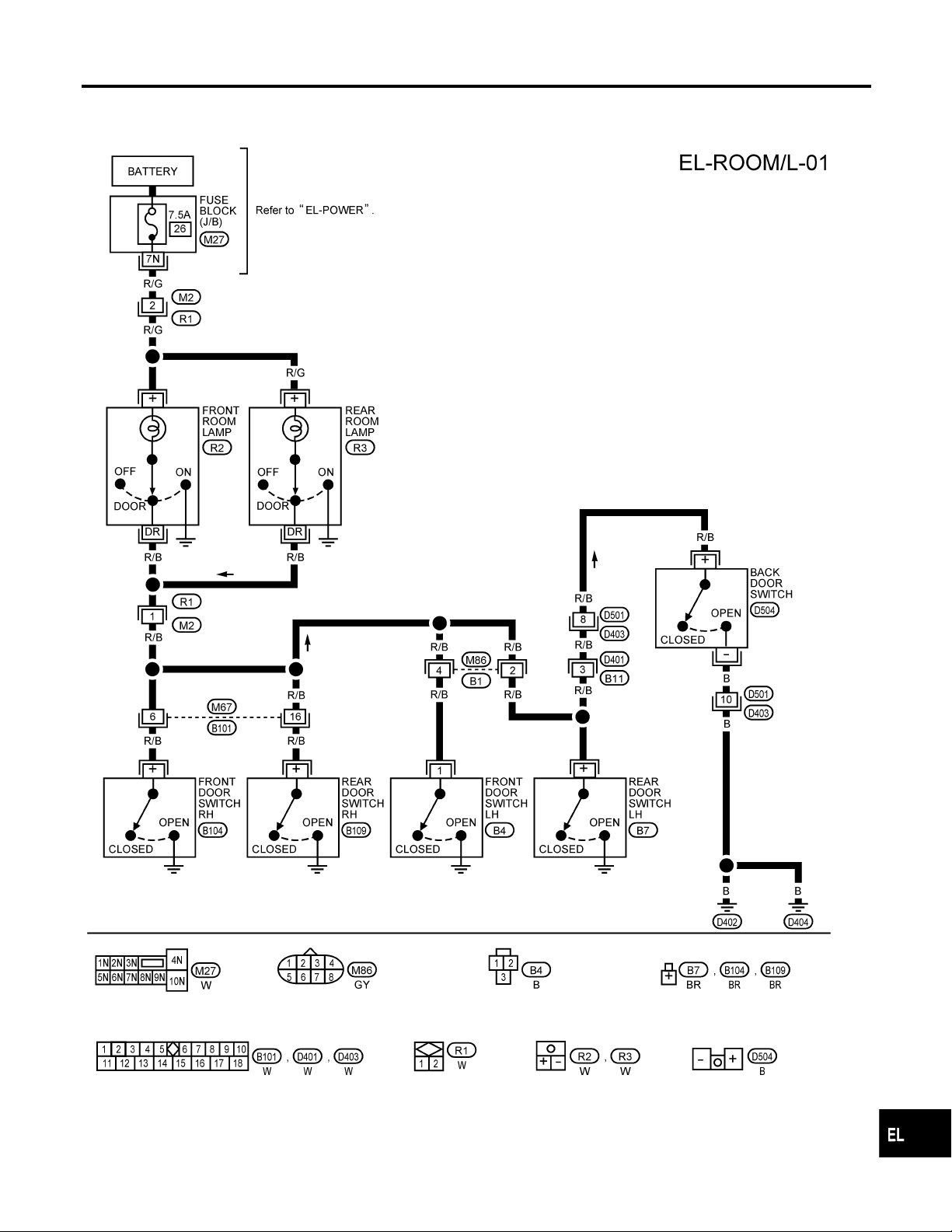
Power is supplied at all times
쐌 through 7.5A fuse [No. 26, located in the fuse block (J/B)]
쐌 to front room lamp terminal + and
쐌 to rear room lamp terminal +.
With the front/rear room lamp switch in the ON position, ground is supplied through the case of the front/rear
room lamp.
With one or more doors open, with the front/rear room lamp switch in the DOOR position, ground is supplied
쐌 to front/rear room lamp terminal DR
쐌 through front door switch LH terminal 1 and/or
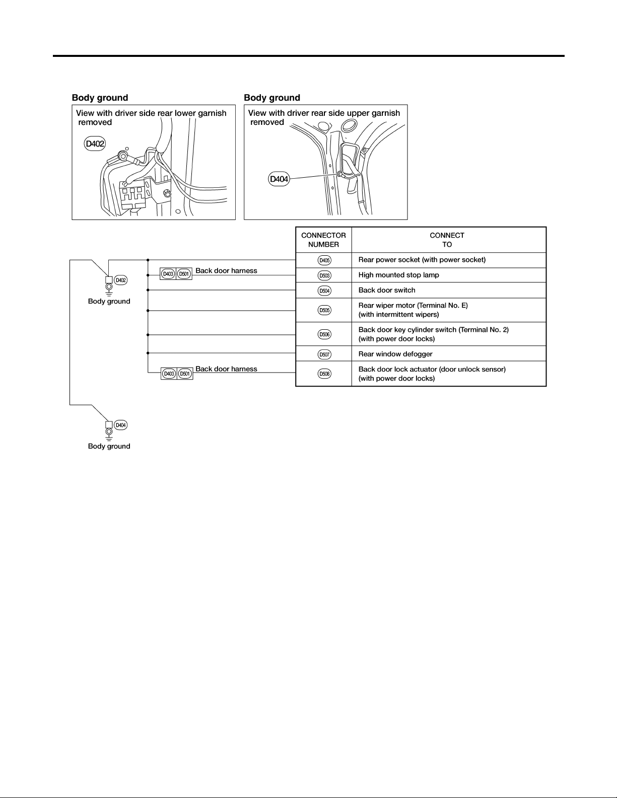
쐌 through front door switch RH, rear door switch LH/RH and/or back door switch terminal +.
Ground is supplied to back door switch terminal – through body grounds D402 and D404.
MODELS WITH POWER DOOR LOCKS
Room Lamp
Power is supplied at all times
쐌 through 7.5A fuse [No. 26, located in the fuse block (J/B)]
쐌 to front room lamp terminal + and
쐌 to rear room lamp terminal +.
With the front/rear room lamp switch in the ON position, ground is supplied through the case of the front/rear
room lamp.
With the front door LH open and the front/rear room lamp switch in the DOOR position, ground is supplied
쐌 to front/rear room lamp terminal DR
쐌 through front door switch LH terminal 1.
With the front door RH open and the front/rear room lamp switch in the DOOR position, ground is supplied
쐌 to smart entrance control unit terminal 35
쐌 through front door switch RH terminal + and
쐌 to front/rear room lamp terminal DR
쐌 through smart entrance control unit terminal 9
쐌 through smart entrance control unit terminal 10
쐌 through body grounds M14 and M68.
With rear door LH/RH and/or back door open and the front/rear room lamp switch in theDOOR position, ground
is supplied
쐌 to smart entrance control unit terminal 16
쐌 through rear door switch LH/RH and/or back door switch terminal + and
쐌 to front/rear room lamp terminal DR
쐌 through smart entrance control unit terminal 9
쐌 through smart entrance control unit terminal 10
쐌 through body grounds M14 and M68.
NGEL0038
NGEL0038S01
NGEL0038S0106
NGEL0038S06
NGEL0038S0601
GI
MA
EM
LC
EC
FE
CL
MT
AT
TF
PD
AX
SU
BR
ST
RS
Room Lamp Timer Operation
When the room lamp switch is in the DOOR position, the smart entrance control unit keeps the room lamp
illuminated for about 30 seconds when:
쐌 unlock signal is supplied from multi-remote controller
쐌 key is removed from ignition key cylinder while front door LH is closed
쐌 driver’s door is opened and then closed while ignition switch is not in the ON position.
The timer is canceled and room lamp turns off when:
쐌 front door LH is locked with multi-remote controller, or
쐌 ignition switch is turned ON.
The smart entrance control unit turns off the room lamp if it is left on for 30 minutes.
NGEL0038S0603
EL-67
BT
HA
SC
IDX

System Description (Cont’d)
INTERIOR ROOM LAMP
Map Lamp
Power is supplied at all times
쐌 through 7.5A fuse [No. 26, located in the fuse block (J/B)]
쐌 to map lamp terminal +
Ground is supplied
쐌 to map lamp terminal –
쐌 through body grounds M14 and M68.
With map lamp switch in ON position, lamp illuminates.
NGEL0038S0602
EL-68
INTERIOR ROOM LAMP
Wiring Diagram — ROOM/L —
Wiring Diagram — ROOM/L —
MODELS WITHOUT POWER DOOR LOCKS
NGEL0040
NGEL0040S01
GI
MA
EM
LC
EC
FE
CL
MT
AT
TF
PD
AX
SU
BR
ST
RS
BT
EL-69
HA
SC
AEL775C
IDX

Wiring Diagram — ROOM/L — (Cont’d)
INTERIOR ROOM LAMP
MODELS WITH POWER DOOR LOCKS
NGEL0040S02
EL-70
AEL386C

INTERIOR ROOM LAMP
Wiring Diagram — ROOM/L — (Cont’d)
GI
MA
EM
LC
EC
FE
CL
MT
AT
TF
PD
AX
SU
BR
ST
RS
EL-71
BT
HA
SC
AEL623C
IDX

METERS AND GAUGES
Component Parts and Harness Connector Location
Component Parts and Harness Connector
Location
NGEL0041
EL-72
AEL429C

METERS AND GAUGES
System Description
System Description
UNIFIED CONTROL METER
쐌 Speedometer, odo/trip meter, tachometer, fuel gauge and water temperature gauge are controlled totally
by unified meter control unit combined with speedometer and odo/trip meter.
쐌 Digital meter is adopted for odo/trip meter.*
*The record of the odo meter is kept even if the battery cable is disconnected. The record of the trip meter
is erased when the battery cable is disconnected.
쐌 Odo/trip meter segment can be checked in diagnosis mode.
쐌 Meter/gauge can be checked in diagnosis mode.
HOW TO CHANGE THE DISPLAY FOR ODO/TRIP METER
NGEL0042
NGEL0042S06
NGEL0042S07
GI
MA
EM
LC
EC
FE
CL
MT
SEL253V
NOTE:
Turn ignition switch ON to operate odo/trip meter.
POWER SUPPLY AND GROUND CIRCUIT
Power is supplied at all times
쐌 through 7.5A fuse [No. 28, located in the fuse block (J/B)]
쐌 to combination meter terminal 18.
With the ignition switch in the ON or START position, power is supplied
쐌 through 10A fuse [No. 11, located in the fuse block (J/B)]
쐌 to combination meter terminal 17.
Ground is supplied
쐌 to combination meter terminal 24
쐌 through body grounds M14 and M68.
FUEL GAUGE
The fuel gauge indicates the approximate fuel level in the fuel tank. The reading on the gauge is based on the
resistance of the fuel tank gauge unit.
The fuel gauge is regulated by a variable ground signal supplied
쐌 to combination meter terminal 20 for the fuel gauge
쐌 through fuel tank gauge unit terminal G
쐌 through fuel tank gauge unit terminal E
쐌 through body grounds B106 and B116.
NGEL0042S08
NGEL0042S03
AT
TF
PD
AX
SU
BR
ST
RS
BT
HA
SC
EL-73
IDX

System Description (Cont’d)
METERS AND GAUGES
WATER TEMPERATURE GAUGE
NGEL0042S01
The water temperature gauge indicates the engine coolant temperature. The reading on the gauge is based
on the resistance of the thermal transmitter.
The water temperature gauge is regulated by a variable ground signal supplied
쐌 to combination meter terminal 19
쐌 through thermal transmitter terminal 1.
As the temperature of the coolant increases, the resistance of the thermal transmitter decreases and the
needle on the gauge moves from C to H.
TACHOMETER
NGEL0042S02
The tachometer indicates engine speed in revolutions per minute (rpm).
The tachometer is regulated by a signal
쐌 to combination meter terminal 21 for the tachometer
쐌 from ECM terminal 3.
SPEEDOMETER
NGEL0042S04
The vehicle speed sensor provides a voltage signal to the combination meter for the speedometer.
The voltage is supplied
쐌 to combination meter terminals 22 and 23 for the speedometer
쐌 from vehicle speed sensor terminals 1 and 2.
The unified meter control unit converts the voltage to the vehicle speed and displays it on the speedometer.
EL-74

METERS AND GAUGES
Combination Meter
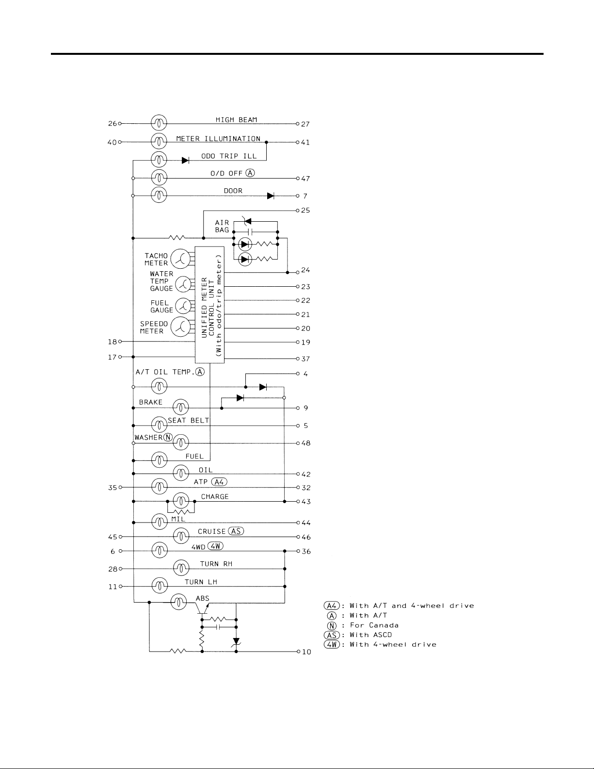
Combination Meter
NGEL0043
GI
MA
EM
LC
EC
FE
CL
MT
AT
TF
PD
AX
SU
BR
ST
RS
BT
EL-75
HA
SC
AEL773C
IDX
Combination Meter (Cont’d)
METERS AND GAUGES
EL-76
AEL774C

METERS AND GAUGES
Wiring Diagram — METER —
Wiring Diagram — METER —
NGEL0045
GI
MA
EM
LC
EC
FE
CL
MT
AT
TF
PD
AX
SU
BR
ST
RS
BT
EL-77
HA
SC
AEL362C
IDX

METERS AND GAUGES
Meter/Gauge Operation and Odo/Trip Meter Segment Check in Diagnosis Mode
Meter/Gauge Operation and Odo/Trip Meter
Segment Check in Diagnosis Mode
DIAGNOSIS FUNCTION
쐌 Odo/trip meter segment can be checked in diagnosis mode.
쐌 Meters/gauges can be checked in diagnosis mode.
NGEL0151
NGEL0151S01
HOW TO ALTERNATE DIAGNOSIS MODE
NGEL0151S02
1. Turn ignition switch ON and change odo/trip meter to TRIP A
or TRIP B.
2. Turn ignition switch OFF.
3. Turn ignition switch ON while pressing and holding odo/trip
meter switch.
4. Confirm that trip meter indicates “000.0”.
5. Push odo/trip meter switch more than 3 times within 5 seconds.
6. All odo/trip meter segments should be turned on.
NOTE:
If some segments are not turned on, speedometer (unified
meter control unit) with odo/trip meter should be replaced.
At this point,the unified metercontrol unit is in diagnosis mode.
SEL110V
SEL111V
7. Push odo/trip meter switch. Indication of each meter/gauge
should be as shown in figure at left while pushing odo/trip
meter switch if it is not malfunctioning.
NOTE:
It takes about 1 minute for indication of fuel gauge to become
stable.
EL-78

METERS AND GAUGES
Trouble Diagnoses
Trouble Diagnoses
PRELIMINARY CHECK
NGEL0046
NGEL0046S04
GI
MA
EM
LC
EC
FE
CL
MT
*1: Meter/Gauge Operation and Odo/
Trip Meter Segment Check in
Diagnosis Mode (EL-78)
*2: METER/GAUGE RESISTANCE
CHECK (EL-85)
*3: POWER SUPPLYAND GROUND
CIRCUIT CHECK (EL-81)
*4: Symptom Chart 1 (EL-80)
*5: Symptom Chart 2 (EL-80)
AT
TF
PD
AX
SU
BR
ST
RS
AEL533C
BT
HA
EL-79
SC
IDX

Trouble Diagnoses (Cont’d)
METERS AND GAUGES
Symptom Possible causes Repair order
Speedometer and/or odo/
trip meter indicate(s) malfunction in Diagnosis
mode.
Multiple meters/gauges
indicate malfunction in
Diagnosis mode.
Tachometer, fuel gauge or
water temp. gauge indicates malfunction in Diagnosis mode.
Symptom Possible causes Repair order
Speedometer and odo/trip
meter are malfunctioning.
SYMPTOM CHART
NGEL0046S05
Symptom Chart 1 (Malfunction is Indicated in
Diagnosis Mode)
쐌 Speedometer (unified meter control unit) 쐌 Replace speedometer (unified meter control unit).
쐌 Meter/Gauge
쐌 Speedometer (unified meter control unit)
1. Check resistance of meter/gauge indicating malfunction. If the resistance is NG, replace the meter/gauge.
Refer to “METER/GAUGE RESISTANCE CHECK”,
EL-85.
2. If the resistance is OK, replace speedometer (unified
meter control unit).
NGEL0046S0501
Symptom Chart 2 (No Malfunction is Indicated in
Diagnosis Mode)
쐌 Sensor
- Speedometer, Odo/Trip meter
쐌 Speedometer (unified meter control unit)
1. Check vehicle speed sensor.
Refer to INSPECTION/VEHICLE SPEED SENSOR,
EL-82.
2. Replace speedometer (unified meter control unit).
NGEL0046S0502
Multiple meters/gauges
are malfunctioning (except
speedometer, odo/trip
meter).
Tachometer, fuel gauge or
water temp. gauge is malfunctioning.
쐌 Speedometer (unified meter control unit) 쐌 Replace speedometer (unified meter control unit).
쐌 Sensor/Engine revolution signal
- Tachometer
- Fuel gauge
- Water temp. gauge
쐌 Speedometer (unified meter control unit)
1. Check the sensor for malfunctioning meter/gauge.
Refer to INSPECTION/ENGINE REVOLUTION
SIGNAL, EL-83.
Refer to INSPECTION/FUEL TANK GAUGE UNIT,
EL-84.
Refer to INSPECTION/THERMAL TRANSMITTER,
EL-85.
2. Replace speedometer (unified meter control unit).
Before starting trouble diagnoses above, perform PRELIMINARY
CHECK, EL-79.
EL-80

METERS AND GAUGES
Trouble Diagnoses (Cont’d)
AEL535C
POWER SUPPLY AND GROUND CIRCUIT CHECK
Power Supply Circuit Check
Terminals Ignition switch position
(+) (−) OFF ACC ON
18 Ground
17 Ground 0V 0V Battery voltage
If NG, check the following.
쐌 7.5A fuse [No. 28, located in fuse block (J/B)]
쐌 10A fuse [No. 11, located in fuse block (J/B)]
쐌 Harness for open or short between fuse and combination
meter
Battery volt-
age
Battery volt-
age
Ground Circuit Check
Terminals Continuity
=NGEL0046S07
NGEL0046S0701
Battery voltage
NGEL0046S0702
GI
MA
EM
LC
EC
FE
CL
MT
AT
AEL536C
24 - Ground Yes
TF
PD
AX
SU
BR
ST
RS
BT
HA
EL-81
SC
IDX

Trouble Diagnoses (Cont’d)
METERS AND GAUGES
INSPECTION/VEHICLE SPEED SENSOR
1 CHECK VEHICLE SPEED SENSOR OUTPUT
1. Remove vehicle speed sensor from transmission.
2. Check voltage between combination meter terminals 22 and 23 while quickly turning speed sensor pinion.
Voltage: Approx. 0.5V
OK or NG
OK 䊳 Vehicle speed sensor is OK.
NG 䊳 GO TO 2.
2 CHECK VEHICLE SPEED SENSOR
Check resistance between vehicle speed sensor terminals 1 and 2.
=NGEL0046S03
AEL537C
Resistance: Approx. 285Ω
OK or NG
OK 䊳 Check harness and connector between speedometer and vehicle speed sensor.
NG 䊳 Replace vehicle speed sensor.
AEL538C
EL-82

METERS AND GAUGES
Trouble Diagnoses (Cont’d)
INSPECTION/ENGINE REVOLUTION SIGNAL
1 CHECK ECM OUTPUT
1. Start engine.
2. Check voltage between combination meter terminals 21 and 24 at idle and 2,000 rpm.
Higher rpm = Higher voltage
Lower rpm = Lower voltage
Voltage should change with rpm.
OK or NG
OK 䊳 Engine revolution signal is OK.
NG 䊳 Harness for open or short between ECM and combination meter
NGEL0046S02
GI
MA
EM
LC
EC
AEL539C
FE
CL
MT
AT
TF
PD
AX
SU
BR
ST
RS
BT
EL-83
HA
SC
IDX

Trouble Diagnoses (Cont’d)
METERS AND GAUGES
INSPECTION/FUEL TANK GAUGE UNIT
1 CHECK GROUND CIRCUIT FOR FUEL TANK GAUGE UNIT
Check harness continuity between fuel tank gauge unit harness connector terminal E and ground.
Does continuity exist?
Yes 䊳 GO TO 2.
No 䊳 Repair harness or connector.
2 CHECK GAUGE UNITS
Refer to “FUEL TANK GAUGE UNIT CHECK”, EL-86.
OK or NG
OK 䊳 GO TO 3.
NG 䊳 Replace fuel tank gauge unit.
=NGEL0046S08
AEL625C
3 CHECK HARNESS FOR OPEN OR SHORT
1. Disconnect combination meter harness connector M38 and fuel tank gauge unit harness connector.
2. Check continuity between combination meter harness connector terminal 20 and fuel tank gauge unit harness connector terminal G.
Continuity should exist.
3. Check continuity between combination meter harness connector terminal 20 and ground.
Continuity should not exist.
AEL626C
OK or NG
OK 䊳 Fuel tank gauge unit is OK.
NG 䊳 Repair harness or connector.
EL-84

METERS AND GAUGES
Trouble Diagnoses (Cont’d)
INSPECTION/THERMAL TRANSMITTER
1 CHECK THERMAL TRANSMITTER
Refer to “THERMAL TRANSMITTER CHECK”, EL-86.
OK or NG
OK 䊳 GO TO 2.
NG 䊳 Replace thermal transmitter.
2 CHECK HARNESS FOR OPEN OR SHORT
1. Disconnect combination meter harness connector M38 and thermal transmitter harness connector.
2. Check continuity between combination meter harness connector terminal 19 and thermal transmitter harness connector
terminal 1.
Continuity should exist.
3. Check continuity between combination meter harness connector terminal 19 and ground.
Continuity should not exist.
NGEL0046S09
GI
MA
EM
LC
EC
FE
CL
MT
OK or NG
OK 䊳 Thermal transmitter is OK.
NG 䊳 Repair harness or connector.
Electrical Components Inspection
METER/GAUGE RESISTANCE CHECK
1. Check resistance between meter/gauge installation screws.
Tachometer Fuel/Temp. gauge
A - C A - C 190 - 260
B-D B-C 230-310
Screws
Resistance
(Approx.)
Ω
AEL542C
NGEL0047
NGEL0047S04
AT
TF
PD
AX
SU
BR
ST
RS
BT
EL-85
HA
SC
LEL006A
IDX

Electrical Components Inspection (Cont’d)
METERS AND GAUGES
MEL827F
FUEL TANK GAUGE UNIT CHECK
NGEL0047S01
쐌 For removal, refer to FE-4.
Check the resistance between fuel tank gauge unit terminals G and
E.
Ohmmeter
(+) (−)
*1 Full 96 (3.78) Approx.4-6
GE
*1 and *3: When float rod is in contact with stopper.
*2 1/2 188 (7.40) 30 - 34
*3 Empty 257 (10.12) 80 - 83
Float position mm (in)
THERMAL TRANSMITTER CHECK
Resistance
value (Ω)
NGEL0047S02
Check the resistance between thermal transmitter terminal 1 and
body ground.
MEL424F
Water temperature Resistance
60°C (140°F) Approx. 170 - 210Ω
100°C (212°F) Approx. 47 - 53Ω
VEHICLE SPEED SENSOR SIGNAL CHECK
NGEL0047S03
1. Remove vehicle speed sensor from transmission.
2. Turn vehicle speed sensor pinion quickly and measure voltage
across a and b.
MEL005H
EL-86

WARNING LAMPS
Circuit Diagram
Circuit Diagram
NGEL0049
GI
MA
EM
LC
EC
FE
CL
MT
AT
TF
PD
AX
SU
BR
ST
RS
BT
EL-87
HA
SC
AEL782C
IDX

Wiring Diagram — WARN —
WARNING LAMPS
Wiring Diagram — WARN —
NGEL0050
EL-88
AEL364C

WARNING LAMPS
Wiring Diagram — WARN — (Cont’d)
MODELS WITHOUT POWER DOOR LOCKS
NGEL0050S01
GI
MA
EM
LC
EC
FE
CL
MT
AT
TF
PD
AX
SU
BR
ST
RS
BT
EL-89
AEL776C
HA
SC
IDX

Wiring Diagram — WARN — (Cont’d)
WARNING LAMPS
MODELS WITH POWER DOOR LOCKS
NGEL0050S02
EL-90
AEL777C

WARNING LAMPS
Wiring Diagram — WARN — (Cont’d)
GI
MA
EM
LC
EC
FE
CL
MT
AT
TF
PD
AX
SU
BR
ST
RS
EL-91
BT
HA
SC
AEL778C
IDX

Wiring Diagram — WARN — (Cont’d)
WARNING LAMPS
EL-92
AEL779C

WARNING LAMPS
Wiring Diagram — WARN — (Cont’d)
GI
MA
EM
LC
EC
FE
CL
MT
AT
TF
PD
AX
SU
BR
ST
RS
EL-93
BT
HA
SC
AEL780C
IDX

Wiring Diagram — WARN — (Cont’d)
WARNING LAMPS
EL-94
AEL781C

WARNING LAMPS
Electrical Components Inspection
Electrical Components Inspection
FUEL WARNING LAMP SENSOR CHECK
NGEL0051
NGEL0051S01
1) Turn ignition switch OFF.
AEL627C
2) Disconnect fuel tank gauge unit harness connector B108.
3) Connect a resistor (80 Ω) between fuel tank gauge unit harness connector terminals G and E .
4) Turn ignition switch ON.
The fuel warning lamp should come on.
NOTE:
ECM might store the 1st tip DTC P0180 during this inspection. If
the DTC is stored in ECM memory, erase the DTC after reconnecting the fuel tank gauge unit harness connector.
Refer to EC-640, “HOW TO ERASE EMISSION-RELATED DIAGNOSTIC INFORMATION”, “Emission-related Diagnostic
Information”, “ON BOARD DIAGNOSTIC SYSTEM DESCRIPTION”.
GI
MA
EM
LC
EC
FE
CL
MT
AT
TF
MEL425F
SEL901F
OIL PRESSURE SWITCH CHECK
Engine start
Engine stop
Oil pressure
kPa (kg/cm
More than 10 - 20
(0.1-0.2,1-3)
Less than 10 - 20
(0.1-0.2,1-3)
2
, psi)
Continuity
NGEL0051S02
NO
YES
Check the continuity between oil pressure switch terminal 1 and
body ground.
DIODE CHECK
NGEL0051S03
쐌 Check continuity using an ohmmeter.
쐌 Diode is functioning properly if test results are as shown in the
figure at left.
쐌 Check diodes at the combination meter harness connector
instead of the combination meter assembly. Refer to “WARNING LAMP” wiring diagrams, EL-88.
NOTE:
Specification may vary depending on the type of tester. Before
performing this inspection, be sure to refer to the instruction
manual of the tester to be used.
EL-95
PD
AX
SU
BR
ST
RS
BT
HA
SC
IDX

WARNING CHIME
Component Parts and Harness Connector Location
Component Parts and Harness Connector
Location
NGEL0052
EL-96
LEL531A

WARNING CHIME
System Description
System Description
MODELS WITHOUT POWER DOOR LOCKS
The warning chime is integral with the warning chime unit, which controls its operation.
Power is supplied at all times
쐌 through 7.5A fuse [No. 28, located in the fuse block (J/B)]
쐌 to key switch terminal 1.
Power is supplied at all times
쐌 through 15A fuse (No. 39, located in the fuse and fusible link box)
쐌 to lighting switch terminal 11.
With the ignition switch in the ON or START position, power is supplied
쐌 through 7.5A fuse [No. 5, located in the fuse block (J/B)]
쐌 to warning chime unit terminal 1.
Ground is supplied to warning chime unit terminal 8 through body grounds M14 and M68.
When a signal, or combination of signals, is received by the warning chime unit, the warning chime will sound.
Ignition Key Warning Chime
With the key switch in the INSERTED (key is in the ignition key cylinder) position, the ignition switch in the
OFF or ACC position and the front door LH open, the warning chime will sound. A battery positive voltage is
supplied
쐌 from key switch terminal 2
쐌 to warning chime unit terminal 5.
Ground is supplied
쐌 to warning chime unit terminal 7
쐌 through front door switch LH terminal 2.
Front door switch LH terminal 3 is grounded through body grounds B6 and B10.
Light Warning Chime
With the ignition switch in the OFF or ACC position, front door LH open and lighting switch in the parking and
tail lamps ON (1ST) or headlamps ON (2ND) position, the warning chime will sound. A battery positive voltage is supplied
쐌 from lighting switch terminal 12
쐌 to warning chime unit terminal 4.
Ground is supplied
쐌 to warning chime unit terminal 7
쐌 through front door switch LH terminal 2.
Front door switch LH terminal 3 is grounded through body grounds B6 and B10.
Seat Belt Warning Chime
The warning chime will sound for approximately 6 seconds when the ignition switch is turned from OFF to ON
with the driver’s seat belt unfastened (seat belt buckle switch ON).
Ground is supplied
쐌 to warning chime unit terminal 2
쐌 through seat belt buckle switch terminal 1.
Seat belt buckle switch terminal 2 is grounded through body grounds M14 and M68.
MODELS WITH POWER DOOR LOCKS
The warning chime is controlled by the smart entrance control unit.
Power is supplied at all times
쐌 through 7.5A fuse [No. 28, located in the fuse block (J/B)]
쐌 to key switch terminal 1.
Power is supplied at all times
쐌 through 15A fuse (No. 39, located in the fuse and fusible link box)
쐌 to lighting switch terminal 11.
Power is supplied at all times
쐌 through 40A fusible link (letter f, located in the fuse and fusible link box).
NGEL0053
NGEL0053S04
NGEL0053S0401
NGEL0053S0402
NGEL0053S0403
NGEL0053S05
EL-97
GI
MA
EM
LC
EC
FE
CL
MT
AT
TF
PD
AX
SU
BR
ST
RS
BT
HA
SC
IDX

WARNING CHIME
System Description (Cont’d)
쐌 to circuit breaker terminal +
쐌 through circuit breaker terminal –
쐌 to smart entrance control unit terminal 1.
With the ignition switch in the ON or START position, power is supplied
쐌 through 7.5A fuse [No. 5, located in the fuse block (J/B)]
쐌 to smart entrance control unit terminal 11.
Ground is supplied to smart entrance control unit terminal 10 through body grounds M14 and M68.
When a signal, or combination of signals, is received by the smart entrance control unit, the warning chime
will sound.
Ignition Key Warning Chime
NGEL0053S0501
With the key switch in the INSERTED (key is in the ignition key cylinder) position, the ignition switch in the
OFF or ACC position and the front door LH open, the warning chime will sound. A battery positive voltage is
supplied
쐌 from key switch terminal 2
쐌 to smart entrance control unit terminal 24.
Ground is supplied
쐌 to smart entrance control unit terminal 15
쐌 through front door switch LH terminal 2.
Front door switch LH terminal 3 is grounded through body grounds B6 and B10.
Light Warning Chime
NGEL0053S0502
With the ignition switch the OFF or ACC position, front door LH open and lighting switch in parking and tail
lamps ON (1ST) or headlamps ON (2ND) position, the warning chime will sound.A battery positive voltage is
supplied
쐌 from lighting switch terminal 12
쐌 to smart entrance control unit terminal 25.
Ground is supplied
쐌 to smart entrance control unit terminal 15
쐌 through front door switch LH terminal 2.
Front door switch LH terminal 3 is grounded through body grounds B6 and B10.
Seat Belt Warning Chime
NGEL0053S0503
The warning chime will sound for approximately 6 seconds when the ignition switch is turned from OFF to ON
with the driver’s seat belt unfastened (seat belt buckle switch ON).
Ground is supplied
쐌 to smart entrance control unit terminal 21
쐌 through seat belt buckle switch terminal 1.
Seat belt buckle switch terminal 2 is grounded through body grounds B6 and B10.
EL-98

WARNING CHIME
Wiring Diagram — CHIME —
Wiring Diagram — CHIME —
MODELS WITHOUT POWER DOOR LOCKS
NGEL0054
NGEL0054S01
GI
MA
EM
LC
EC
FE
CL
MT
AT
TF
PD
AX
SU
BR
ST
RS
BT
EL-99
HA
SC
AEL387C
IDX

Wiring Diagram — CHIME — (Cont’d)
WARNING CHIME
MODELS WITH POWER DOOR LOCKS
NGEL0054S02
EL-100
AEL388C
 Loading...