


AUTOMATIC TRANSMISSION
GI
MA
CONTENTS
TROUBLE DIAGNOSIS - INDEX ....................................4
Alphabetical & P No. Index for DTC ...........................4
PRECAUTIONS ...............................................................6
Supplemental Restraint System (SRS) ″AIR
BAG″ and ″SEAT BELT PRE-TENSIONER″...............6
Precautions for On Board Diagnostic (OBD)
System of A/T and Engine...........................................6
Precautions..................................................................6
Service Notice or Precautions.....................................8
Wiring Diagrams and Trouble Diagnosis.....................9
PREPARATION .............................................................10
Special Service Tools................................................10
OVERALL SYSTEM ......................................................12
A/T Electrical Parts Location .....................................12
Circuit Diagram..........................................................13
Cross-sectional View .................................................14
Hydraulic Control Circuit............................................15
Shift Mechanism ........................................................16
Control System ..........................................................25
Control Mechanism....................................................26
Control Valve .............................................................31
ON BOARD DIAGNOSTIC SYSTEM
DESCRIPTION...............................................................33
Introduction................................................................33
OBD-II Function for A/T System................................33
One or Two Trip Detection Logic of OBD-II..............33
OBD-II Diagnostic Trouble Code (DTC)....................33
Malfunction Indicator Lamp (MIL)..............................37
CONSULT-II...............................................................37
Diagnostic Procedure Without CONSULT-II..............46
TROUBLE DIAGNOSIS - INTRODUCTION..................53
Introduction................................................................53
Work Flow..................................................................57
TROUBLE DIAGNOSIS - BASIC INSPECTION...........59
A/T Fluid Check.........................................................59
Stall Test....................................................................59
Line Pressure Test.....................................................62
Road Test...................................................................63
SECTION
TROUBLE DIAGNOSIS - GENERAL
DESCRIPTION...............................................................81
Symptom Chart..........................................................81
TCM Terminals and Reference Value........................92
TROUBLE DIAGNOSIS FOR POWER SUPPLY..........96
Wiring Diagram - AT - MAIN......................................96
DTC P0705 PARK/NEUTRAL POSITION (PNP)
SWITCH .........................................................................99
Description.................................................................99
Wiring Diagram - AT - PNP/SW...............................101
Diagnostic Procedure ..............................................102
Component Inspection.............................................104
DTC P0710 A/T FLUID TEMPERATURE SENSOR
CIRCUIT.......................................................................105
Description...............................................................105
Wiring Diagram - AT - FTS......................................107
Diagnostic Procedure ..............................................108
Component Inspection.............................................110
DTC P0720 VEHICLE SPEED SENSOR.A/T
(REVOLUTION SENSOR) ...........................................111
Description............................................................... 111
Wiring Diagram - AT - VSSA/T................................113
Diagnostic Procedure ..............................................114
Component Inspection.............................................115
DTC P0725 ENGINE SPEED SIGNAL .......................116
Description...............................................................116
Wiring Diagram - AT - ENGSS................................117
Diagnostic Procedure ..............................................118
DTC P0731 IMPROPER SHIFTING TO 1ST GEAR
POSITION ....................................................................120
Description...............................................................120
Wiring Diagram - AT - 1ST......................................123
Diagnostic Procedure ..............................................124
Component Inspection.............................................125
DTC P0732 IMPROPER SHIFTING TO 2ND GEAR
POSITION ....................................................................126
Description...............................................................126
Wiring Diagram - AT - 2ND......................................129
Diagnostic Procedure ..............................................130
AT
EM
LC
EC
FE
CL
MT
TF
PD
AX
SU
BR
ST
RS
BT
HA
SC
EL
IDX

CONTENTS (Cont’d)
Component Inspection.............................................130
DTC P0733 IMPROPER SHIFTING TO 3RD GEAR
POSITION ....................................................................132
Description...............................................................132
Wiring Diagram - AT - 3RD......................................135
Diagnostic Procedure ..............................................136
Component Inspection.............................................136
DTC P0734 IMPROPER SHIFTING TO 4TH GEAR
POSITION ....................................................................138
Description...............................................................138
Wiring Diagram - AT - 4TH......................................142
Diagnostic Procedure ..............................................143
Component Inspection.............................................146
DTC P0740 TORQUE CONVERTER CLUTCH
SOLENOID VALVE......................................................147
Description...............................................................147
Wiring Diagram - AT - TCV......................................149
Diagnostic Procedure ..............................................150
Component Inspection.............................................151
DTC P0744 IMPROPER LOCK-UP OPERATION......152
Description...............................................................152
Wiring Diagram - AT - TCCSIG...............................155
Diagnostic Procedure ..............................................156
Component Inspection.............................................159
DTC P0745 LINE PRESSURE SOLENOID VALVE...160
Description...............................................................160
Wiring Diagram - AT - LPSV....................................162
Diagnostic Procedure ..............................................163
Component Inspection.............................................164
DTC P0750 SHIFT SOLENOID VALVE A ..................165
Description...............................................................165
Wiring Diagram - AT - SSV/A..................................167
Diagnostic Procedure ..............................................168
Component Inspection.............................................169
DTC P0755 SHIFT SOLENOID VALVE B..................170
Description...............................................................170
Wiring Diagram - AT - SSV/B..................................172
Diagnostic Procedure ..............................................173
Component Inspection.............................................174
DTC P1705 THROTTLE POSITION SENSOR ...........175
Description...............................................................175
Wiring Diagram - AT - TPS......................................178
Diagnostic Procedure ..............................................179
Component Inspection.............................................183
DTC P1760 OVERRUN CLUTCH SOLENOID
VALVE..........................................................................184
Description...............................................................184
Wiring Diagram - AT - OVRCSV..............................186
Diagnostic Procedure ..............................................187
Component Inspection.............................................188
DTC BATT/FLUID TEMP SEN (A/T FLUID TEMP
SENSOR CIRCUIT AND TCM POWER SOURCE)....189
Description...............................................................189
Wiring Diagram - AT - BA/FTS................................191
Diagnostic Procedure ..............................................192
Component Inspection.............................................194
VEHICLE SPEED SENSOR.MTR................................195
Description...............................................................195
Wiring Diagram - AT - VSSMTR..............................197
Diagnostic Procedure ..............................................198
DTC CONTROL UNIT (RAM), CONTROL UNIT
(ROM)...........................................................................199
Description...............................................................199
Diagnostic Procedure ..............................................200
DTC CONTROL UNIT (EEPROM) ..............................201
Description...............................................................201
Diagnostic Procedure ..............................................202
TROUBLE DIAGNOSES FOR SYMPTOMS...............203
Wiring Diagram - AT - NONDTC.............................203
1. O/D OFF Indicator Lamp Does Not Come On....206
2. Engine Cannot Be Started In P and N Position..208
3. In ″P″ Position, Vehicle Moves Forward Or
Backward When Pushed.........................................209
4. In N Position, Vehicle Moves ..............................210
5. Large Shock. N -> R Position.............................212
6. Vehicle Does Not Creep Backward In R
Position....................................................................214
7. Vehicle Does Not Creep Forward In D, 2 Or 1
Position....................................................................217
8. Vehicle Cannot Be Started From D
9. A/T Does Not Shift: D
Kickdown: D
-> D2..................................................223
4
10. A/T Does Not Shift: D
11. A/T Does Not Shift: D
-> D2Or Does Not
1
-> D3.............................226
2
-> D4.............................229
3
...................220
1
12. A/T Does Not Perform Lock-up.........................232
13. A/T Does Not Hold Lock-up Condition..............234
14. Lock-up Is Not Released...................................236
15. Engine Speed Does Not Return To Idle (Light
Braking D
16. Vehicle Does Not Start From D
17. A/T Does Not Shift: D
-> D3).....................................................237
4
.......................239
1
-> D3, When
4
Overdrive Control Switch ON -> OFF .....................240
18. A/T Does Not Shift: D
-> 22, When Selector
3
Lever D -> 2 Position ..............................................241
19. A/T Does Not Shift: 2
-> 11, When Selector
2
Lever 2 -> 1 Position...............................................242
20. Vehicle Does Not Decelerate By Engine
Brake........................................................................243
21. TCM Self-diagnosis Does Not Activate (PNP,
Overdrive Control and Throttle Position Switches
Circuit Checks) ........................................................243
A/T SHIFT LOCK SYSTEM.........................................251
Description...............................................................251
Wiring Diagram - SHIFT -........................................252
AT-2

CONTENTS (Cont’d)
Diagnostic Procedure ..............................................253
Component Check...................................................255
KEY INTERLOCK CABLE ..........................................256
Components.............................................................256
Removal...................................................................256
Installation................................................................257
ON-VEHICLE SERVICE ..............................................258
Control Valve Assembly and Accumulators.............258
Revolution Sensor Replacement.............................259
Rear Oil Seal Replacement.....................................259
Parking Components Inspection..............................259
Park/Neutral Position (PNP) Switch Adjustment .....260
Manual Control Linkage Adjustment........................260
REMOVAL AND INSTALLATION...............................261
Removal...................................................................261
Installation................................................................263
OVERHAUL .................................................................264
Components.............................................................264
Oil Channel..............................................................266
Locations of Needle Bearings, Thrust Washers
and Snap Rings.......................................................267
DISASSEMBLY............................................................268
REPAIR FOR COMPONENT PARTS .........................279
Oil Pump..................................................................279
Control Valve Assembly...........................................283
Control Valve Upper Body.......................................289
Control Valve Lower Body.......................................294
Reverse Clutch ........................................................296
High Clutch ..............................................................300
Forward and Overrun Clutches ...............................302
Low & Reverse Brake..............................................306
Forward Clutch Drum Assembly..............................310
Rear Internal Gear and Forward Clutch Hub..........312
Band Servo Piston Assembly..................................315
Parking Pawl Components......................................319
ASSEMBLY..................................................................321
Assembly (1)............................................................321
Adjustment...............................................................329
Assembly (2)............................................................331
SERVICE DATA AND SPECIFICATIONS (SDS).......338
General Specifications.............................................338
Shift Schedule..........................................................338
Stall Revolution........................................................338
Line Pressure...........................................................338
Return Springs.........................................................339
Accumulator O-ring..................................................340
Clutches and Brakes ...............................................340
Oil Pump and Low One-way Clutch........................342
Total End Play..........................................................342
Reverse Clutch Drum End Play ..............................343
Removal and Installation.........................................343
GI
MA
EM
LC
EC
FE
CL
MT
TF
PD
AX
SU
BR
ST
RS
BT
HA
SC
AT-3
EL
IDX

Alphabetical & P No. Index for DTC
TROUBLE DIAGNOSIS — INDEX
Alphabetical & P No. Index for DTC
ALPHABETICAL INDEX FOR DTC
Items
(CONSULT-II screen terms)
A/T 1ST GR FNCTN 1103 P0731 AT-120
A/T 2ND GR FNCTN 1104 P0732 AT-126
A/T 3RD GR FNCTN 1105 P0733 AT-132
A/T 4TH GR FNCTN 1106 P0734 AT-138
A/T TCC S/V FNCTN 1107 P0744 AT-152
ATF TEMP SEN/CIRC 1208 P0710 AT-105
ENGINE SPEED SIG 1207 P0725 AT-116
L/PRESS SOL/CIRC 1205 P0745 AT-160
O/R CLTCH SOL/CIRC 1203 P1760 AT-184
PNP SW/CIRC 1101 P0705 AT-99
SFT SOL A/CIRC*3 1108 P0750 AT-165
SFT SOL B/CIRC*3 1201 P0755 AT-170
ECM*1
DTC
CONSULT-II
GST*2
Reference page
NGAT0179
NGAT0179S01
TCC SOLENOID/CIRC 1204 P0740 AT-147
TP SEN/CIRC A/T*3 1206 P1705 AT-175
VEH SPD SEN/CIR AT*4 1102 P0720 AT-111
*1: In Diagnostic Test Mode II (Self-diagnostic results), these numbers are controlled by NISSAN.
*2: These numbers are prescribed by SAE J2012.
*3: When the fail-safe operation occurs, the MIL illuminates.
*4: The MIL illuminates when both the “Revolution sensor signal” and the “Vehicle speed sensor signal” meet the fail-safe condition at
the same time.
AT-4

TROUBLE DIAGNOSIS — INDEX
Alphabetical & P No. Index for DTC (Cont’d)
P NO. INDEX FOR DTC
DTC
CONSULT-II
GST*2
P0705 1101 PNP SW/CIRC AT-99
P0710 1208 ATF TEMP SEN/CIRC AT-105
P0720 1102 VEH SPD SEN/CIR AT*4 AT-111
P0725 1207 ENGINE SPEED SIG AT-116
P0731 1103 A/T 1ST GR FNCTN AT-120
P0732 1104 A/T 2ND GR FNCTN AT-126
P0733 1105 A/T 3RD GR FNCTN AT-132
P0734 1106 A/T 4TH GR FNCTN AT-138
P0740 1204 TCC SOLENOID/CIRC AT-147
P0744 1107 A/T TCC S/V FNCTN AT-152
P0745 1205 L/PRESS SOL/CIRC AT-160
P0750 1108 SFT SOL A/CIRC*3 AT-165
P0755 1201 SFT SOL B/CIRC*3 AT-170
ECM*1
Items
(CONSULT-II screen terms)
=NGAT0179S02
GI
Reference page
MA
EM
LC
EC
FE
CL
MT
P1705 1206 TP SEN/CIRC A/T*3 AT-175
P1760 1203 O/R CLTCH SOL/CIRC AT-184
*1: In Diagnostic Test Mode II (Self-diagnostic results), these numbers are controlled by NISSAN.
*2: These numbers are prescribed by SAE J2012.
*3: When the fail-safe operation occurs, the MIL illuminates.
*4: The MIL illuminates when both the “Revolution sensor signal” and the “Vehicle speed sensor signal” meet the fail-safe condition at
the same time.
TF
PD
AX
SU
BR
ST
RS
BT
AT-5
HA
SC
EL
IDX

PRECAUTIONS
Supplemental Restraint System (SRS) “AIR BAG” and “SEAT BELT PRE-TENSIONER”
Supplemental Restraint System (SRS) “AIR
BAG” and “SEAT BELT PRE-TENSIONER”
The supplemental Restraint System such as “AIR BAG” and “SEAT BELTPRE-TENSIONER” used along with
a seat belt, helps to reduce the risk or severity of injury to the driver and front passenger for certain types of
collision. The Supplemental Restraint System consists of driver air bag module (located in the center of the
steering wheel), front passenger air bag module (located on the instrument panel on passenger side), seat
belt pre-tensioners, a diagnosis sensor unit, a crash zone sensor, warning lamp, wiring harness and spiral
cable.
Information necessary to service the system safely is included in the RS section of this Service Manual.
WARNING:
I To avoid rendering the SRS inoperative, which could increase the risk of personal injury or death
in the event of a collision which would result in air bag inflation, all maintenance must be performed
by an authorized NISSAN dealer.
I Improper maintenance, including incorrect removal and installation of the SRS, can lead to per-
sonal injury caused by unintentional activation of the system. For removal of Spiral Cable and Air
Bag Module, refer to
I Do not use electrical test equipment on any circuit related to the SRS unless instructed to in this
Service Manual. Spiral cable and wiring harnesses (except “SEAT BELT PRE-TENSIONER”) covered with yellow insulation either just before the harness connectors or for the complete harness
are related to the SRS.
RS-16
.
NGAT0001
Precautions for On Board Diagnostic (OBD) System of A/T and Engine
The ECM has an on board diagnostic system. It will light up the malfunction indicator lamp (MIL) to warn the
driver of a malfunction causing emission deterioration.
CAUTION:
I Be sure to turn the ignition switch OFF and disconnect the negative battery terminal before any
repair or inspection work. The open/short circuit of related switches, sensors, solenoid valves, etc.
will cause the MIL to light up.
I Be sure to connect and lock the connectors securely after work. A loose (unlocked) connector will
cause the MIL to light up due to an open circuit. (Be sure the connector is free from water, grease,
dirt, bent terminals, etc.)
I Be sure to route and secure the harnesses properly after work. Interference of the harness with a
bracket, etc. may cause the MIL to light up due to a short circuit.
I Be sure to connect rubber tubes properly after work. A misconnected or disconnected rubber tube
may cause the MIL to light up due to a malfunction of the EGR system or fuel injection system,
etc.
I Be sure to erase the unnecessary malfunction information (repairs completed) from the TCM and
ECM before returning the vehicle to the customer.
NGAT0002
SEF289H
Precautions
I Before connecting or disconnecting the TCM harness
connector, turn ignition switch OFF and disconnect negative battery terminal. Failure to do so may damage the
TCM. Because battery voltage is applied to TCM even if
ignition switch is turned off.
NGAT0003
AT-6
PRECAUTIONS
Precautions (Cont’d)
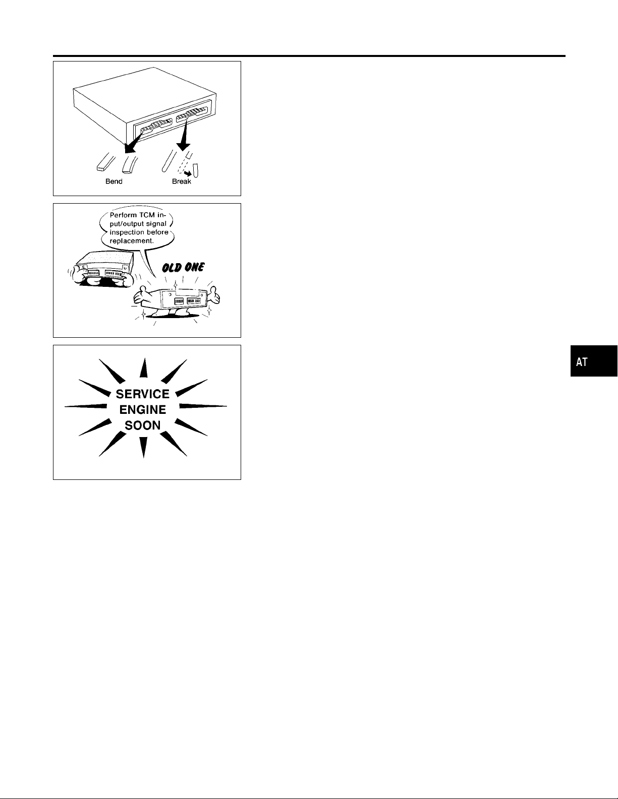
I When connecting or disconnecting pin connectors into or
from TCM, take care not to damage pin terminals (bend or
break).
Make sure that there are not any bends or breaks on TCM
pin terminal, when connecting pin connectors.
GI
MA
EM
AAT470A
MEF040DA
SAT964I
I Before replacing TCM, perform TCM input/output signal
inspection and make sure whether TCM functions properly or not. (See page AT-92.)
I After performing each TROUBLE DIAGNOSIS, perform
“DTC (Diagnostic Trouble Code) CONFIRMATION PROCEDURE”.
The DTC should not be displayed in the “DTC CONFIRMATION PROCEDURE” if the repair is completed.
I Before proceeding with disassembly, thoroughly clean the out-
side of the transmission. It is important to prevent the internal
parts from becoming contaminated by dirt or other foreign matter.
I Disassembly should be done in a clean work area.
I Use lint-free cloth or towels for wiping parts clean. Common
shop rags can leave fibers that could interfere with the operation of the transmission.
I Place disassembled parts in order for easier and proper
assembly.
I All parts should be carefully cleaned with a general purpose,
non-flammable solvent before inspection or reassembly.
I Gaskets, seals and O-rings should be replaced any time the
transmission is disassembled.
I It is very important to perform functional tests whenever they
are indicated.
I The valve body contains precision parts and requires extreme
care when parts are removed and serviced. Place disassembled valve body parts in order for easier and proper
assembly. Care will also prevent springs and small parts from
becoming scattered or lost.
I Properly installed valves, sleeves, plugs, etc. will slide along
bores in valve body under their own weight.
AT-7
LC
EC
FE
CL
MT
TF
PD
AX
SU
BR
ST
RS
BT
HA
SC
EL
IDX

Precautions (Cont’d)
PRECAUTIONS
I Before assembly, apply a coat of recommended ATF to all
parts. Apply petroleum jelly to protect O-rings and seals, or
hold bearings and washers in place during assembly. Do not
use grease.
I Extreme care should be taken to avoid damage to O-rings,
seals and gaskets when assembling.
I Replace ATF cooler if excessive foreign material is found in oil
pan or clogging strainer. Refer to “ATF COOLER SERVICE”
(Refer to AT-9).
I After overhaul, refill the transmission with new ATF.
I When the A/T drain plug is removed, only some of the fluid is
drained. Old A/T fluid will remain in torque converter and ATF
cooling system.
Always follow the procedures under “Changing A/T Fluid” refer
to
MA-37
whenchangingA/Tfluid.
Service Notice or Precautions
FAIL-SAFE
NGAT0004
NGAT0004S01
The TCM has an electronic Fail-Safe (limp home mode). This allows the vehicle to be driven even if a major
electrical input/output device circuit is damaged.
Under Fail-Safe, the vehicle always runs in third gear, even with a shift lever position of 1, 2 or D. The customer may complain of sluggish or poor acceleration.
When the ignition key is turned ON following Fail-Safe operation, O/D OFF indicator lamp blinks for about 8
seconds. (For “TCM SELF-DIAGNOSTIC PROCEDURE (No Tools)”, refer to AT-47.)
Fail-Safe may occur without electrical circuit damage if the vehicle is driven under extreme conditions (such
as excessive wheel spin followed by sudden braking). To recover normal shift pattern, turn the ignition key
OFF for 5 seconds, then ON.
The blinking of the O/D OFF indicator lamp for about 8 seconds will appear only once and be cleared. The
customer may resume normal driving conditions.
Always follow the “WORK FLOW” (Refer to AT-57).
The SELF-DIAGNOSIS results will be as follows:
The first SELF-DIAGNOSIS will indicate damage to the vehicle speed sensor or the revolution sensor.
During the next SELF-DIAGNOSIS, performed after checking the sensor, no damages will be indicated.
TORQUE CONVERTER SERVICE
NGAT0004S04
The torque converter should be replaced under any of the following conditions:
I External leaks in the hub weld area.
I Converter hub is scored or damaged.
I Converter pilot is broken, damaged or fits poorly into crankshaft.
I Steel particles are found after flushing the cooler and cooler lines.
I Pump is damaged or steel particles are found in the converter.
I Vehicle has TCC shudder and/or no TCC apply. Replace only after all hydraulic and electrical diagnoses
have been made. (Converter clutch material may be glazed.)
I Converter is contaminated with engine coolant containing antifreeze.
I Internal failure of stator roller clutch.
I Heavy clutch debris due to overheating (blue converter).
I Steel particles or clutch lining material found in fluid filter or on magnet when no internal parts in unit are
worn or damaged — indicates that lining material came from converter.
The torque converter should not be replaced if:
I The fluid has an odor, is discolored, and there is no evidence of metal or clutch facing particles.
AT-8

PRECAUTIONS
Service Notice or Precautions (Cont’d)
I The threads in one or more of the converter bolt holes are damaged.
I Transmission failure did not display evidence of damaged or worn internal parts, steel particles or clutch
plate lining material in unit and inside the fluid filter.
I Vehiclehas been exposed to high mileage (only). The exception may be where the torque converter clutch
dampener plate lining has seen excess wear by vehicles operated in heavy and/or constant traffic, such
as taxi, delivery or police use.
GI
MA
ATF COOLER SERVICE
Replace ATF cooler if excessive foreign material is found in oil pan or clogging strainer.
Replace radiator lower tank (which includes ATF cooler) with a new one and flush cooler line using cleaning
solvent and compressed air.
OBD-II SELF-DIAGNOSIS
I A/T self-diagnosis is performed by the TCM in combination with the ECM. The results can be read through
the blinking pattern of the O/D OFF indicator or the malfunction indicator lamp (MIL). Refer to the table on
AT-38 for the indicator used to display each self-diagnostic result.
I The self-diagnostic results indicated by the MIL are automatically stored in both the ECM and TCM
memories.
Always perform the procedure “HOW TO ERASE DTC” on AT-35 to complete the repair and avoid
unnecessary blinking of the MIL.
I The following self-diagnostic items can be detected using ECM self-diagnostic results mode* only when
the O/D OFF indicator lamp does not indicate any malfunctions.
− Park/neutral position (PNP) switch
− A/T 1st, 2nd, 3rd, or 4th gear function
− A/T TCC S/V function (lock-up)
*: For details of OBD-II, refer to
I Certain systems and components, especially those related to OBD, may use a new style slide-
locking type harness connector. For description and how to disconnect, refer to
“Description”, “HARNESS CONNECTOR”.
EC-627
(“ON BOARD DIAGNOSTIC SYSTEM DESCRIPTION”).
Wiring Diagrams and Trouble Diagnosis
When you read wiring diagrams, refer to the followings:
GI-10
I “HOW TO READ WIRING DIAGRAMS” refer to
I “POWER SUPPLY ROUTING” for power distribution circuit refer to
When you perform trouble diagnosis, refer to the followings:
I “HOW TO FOLLOW TEST GROUP IN TROUBLE DIAGNOSIS” refer to
I “HOW TO PERFORM EFFICIENT DIAGNOSIS FOR AN ELECTRICAL INCIDENT” refer to
.
EL-9
.
GI-34
.
GI-23
NGAT0004S02
NGAT0004S03
EL-5
NGAT0005
.
,
EM
LC
EC
FE
CL
MT
TF
PD
AX
SU
AT-9
BR
ST
RS
BT
HA
SC
EL
IDX
Special Service Tools
PREPARATION
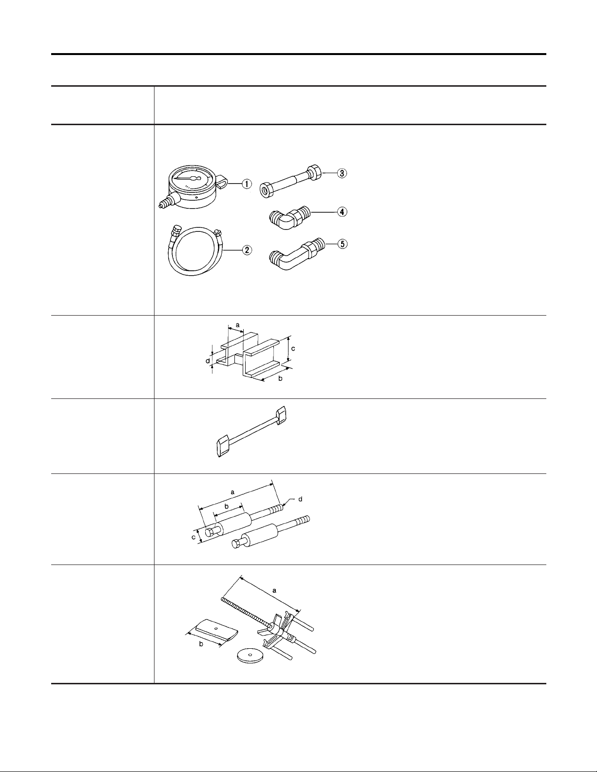
Special Service Tools
The actual shapes of Kent-Moore tools may differ from those of special service tools illustrated here.
Tool number
(Kent-Moore No.)
Tool name
ST2505S001
(J34301-C)
Oil pressure gauge set
1 ST25051001
(—)
Oil pressure gauge
2 ST25052000
(—)
Hose
3 ST25053000
(—)
Joint pipe
4 ST25054000
(—)
Adapter
5 ST25055000
(—)
Adapter
ST07870000
(J37068)
Transmission case stand
Description
Measuring line pressure
NT097
Disassembling and assembling A/T
a: 182 mm (7.17 in)
b: 282 mm (11.10 in)
c: 230 mm (9.06 in)
d: 100 mm (3.94 in)
NGAT0006
KV31102100
(J37065)
Torque converter oneway clutch check tool
ST25850000
(J25721-A)
Sliding hammer
KV31102400
(J34285 and J34285-87)
Clutch spring compressor
NT421
Checking one-way clutch in torque converter
NT098
Removing oil pump assembly
a: 179 mm (7.05 in)
b: 70 mm (2.76 in)
c: 40 mm (1.57 in) dia.
d: M12 x 1.75P
NT422
Removing and installing clutch return springs
a: 320 mm (12.60 in)
b: 174 mm (6.85 in)
NT423
AT-10
Tool number
(Kent-Moore No.)
Tool name
PREPARATION
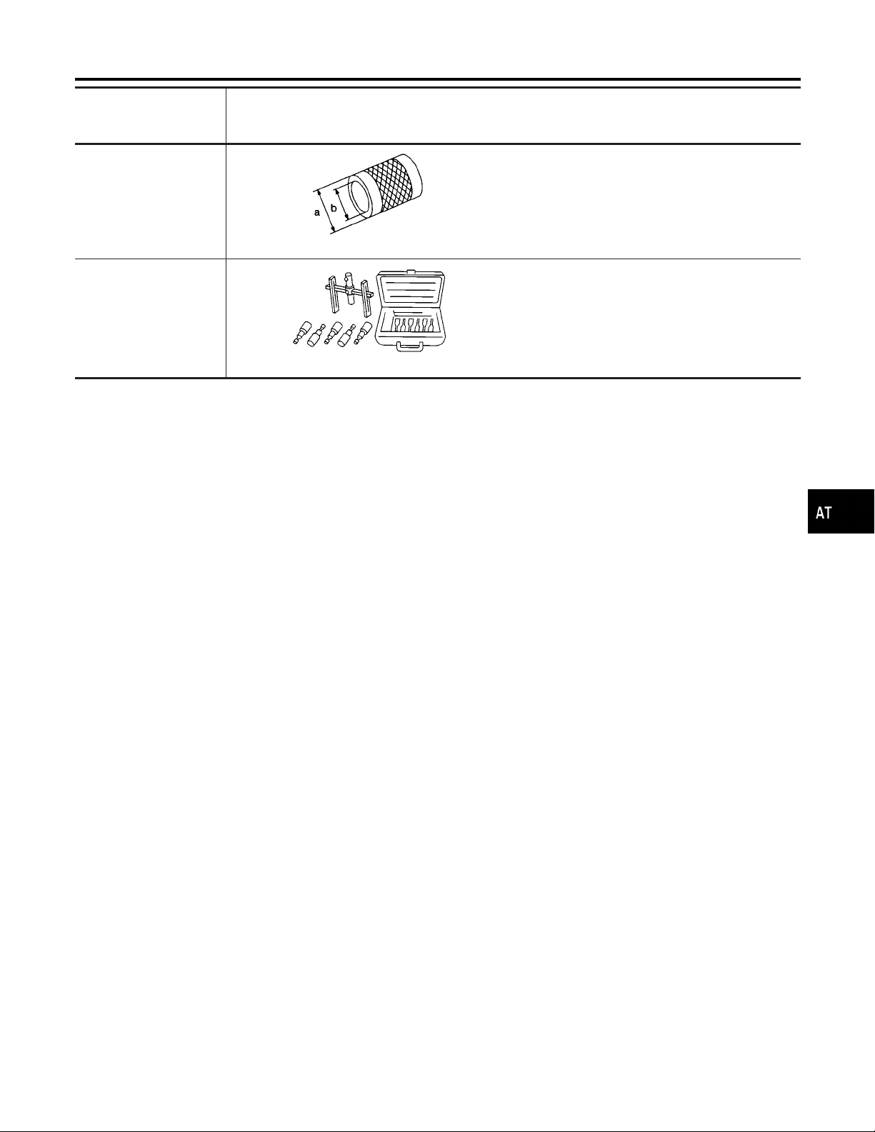
Special Service Tools (Cont’d)
Description
GI
ST33200000
(J26082)
Drift
(J34291)
Shim setting gauge set
NT091
NT101
Installing oil pump housing oil seal Installing rear
oil seal
a: 60 mm (2.36 in) dia.
b: 44.5 mm (1.752 in) dia.
Selecting oil pump cover bearing race and oil
pump thrust washer
MA
EM
LC
EC
FE
CL
MT
TF
PD
AX
SU
BR
ST
RS
BT
HA
SC
AT-11
EL
IDX
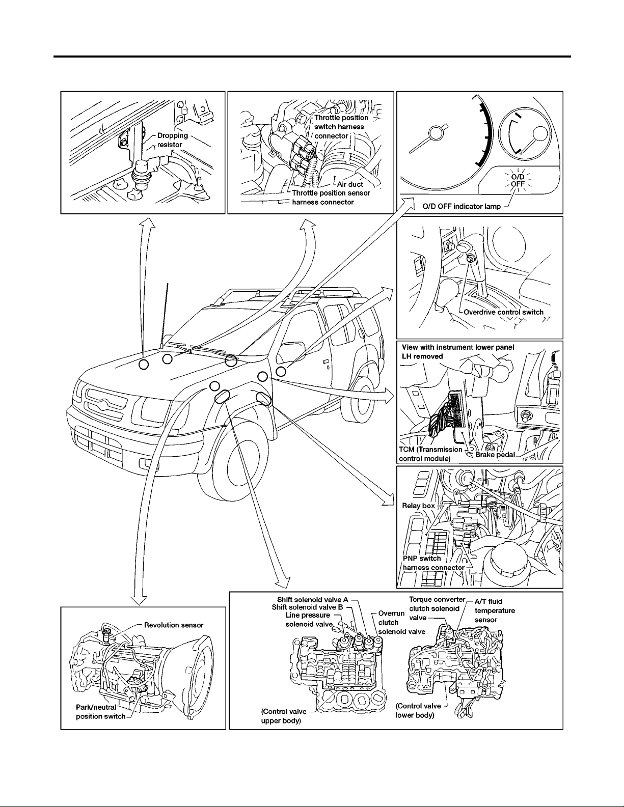
A/T Electrical Parts Location
OVERALL SYSTEM
A/T Electrical Parts Location
NGAT0007
AT-12
AAT622A
OVERALL SYSTEM
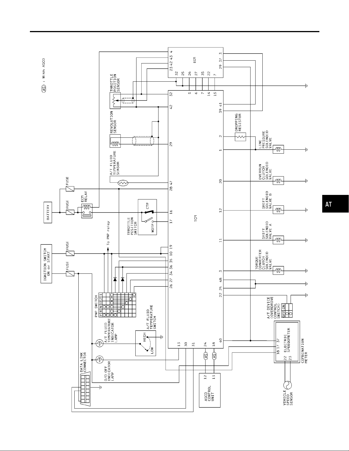
Circuit Diagram
Circuit Diagram
NGAT0008
GI
MA
EM
LC
EC
FE
CL
MT
TF
PD
AX
SU
BR
ST
RS
BT
HA
AT-13
AAT580A
SC
EL
IDX
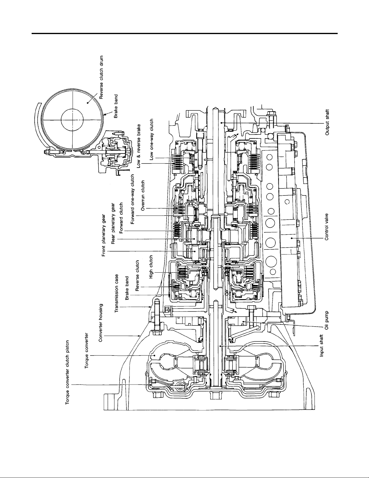
Cross-sectional View
OVERALL SYSTEM
Cross-sectional View
NGAT0010
AT-14
SAT125BA
OVERALL SYSTEM
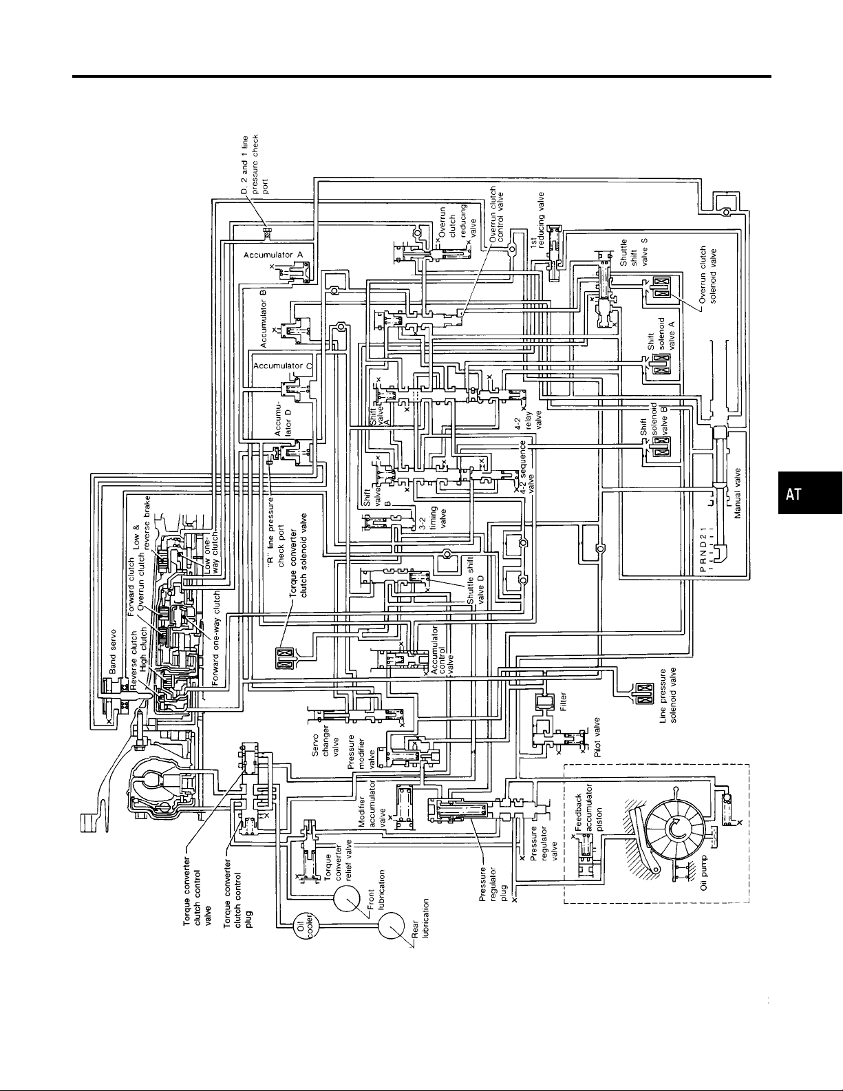
Hydraulic Control Circuit
Hydraulic Control Circuit
NGAT0011
GI
MA
EM
LC
EC
FE
CL
MT
TF
PD
AX
SU
BR
ST
RS
BT
HA
AT-15
SAT624GA
SC
EL
IDX
Shift Mechanism
OVERALL SYSTEM
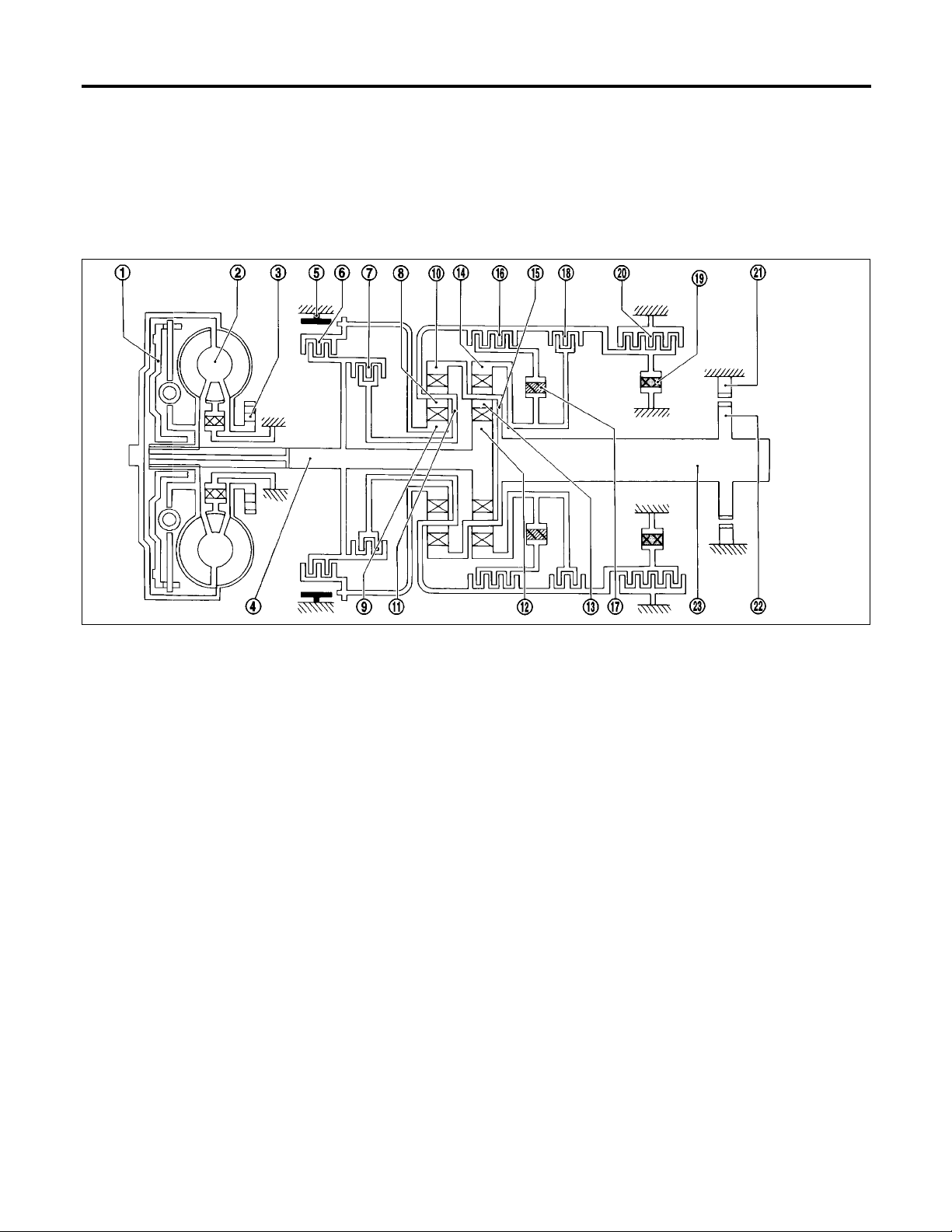
Shift Mechanism
NGAT0012
The automatic transmission uses compact, dual planetary gear systems to improve power-transmission
efficiency, simplify construction and reduce weight.
It also employs an optimum shift control and superwide gear ratios. They improve starting performance and
acceleration during medium and high-speed operation.
Two one-way clutches are also employed: one is used for the forward clutch and the other for the low clutch.
These one-way clutches, combined with four accumulators, reduce shifting shock to a minimum.
CONSTRUCTION
NGAT0012S01
1. Torque converter clutch piston
2. Torque converter
3. Oil pump
4. Input shaft
5. Brake band
6. Reverse clutch
7. High clutch
8. Front pinion gear
9. Front sun gear
10. Front internal gear
11. Front planetary carrier
12. Rear sun gear
13. Rear pinion gear
14. Rear internal gear
15. Rear planetary carrier
16. Forward clutch
SAT509I
17. Forward one-way clutch
18. Overrun clutch
19. Low one-way clutch
20. Low & reverse brake
21. Parking pawl
22. Parking gear
23. Output shaft
AT-16
OVERALL SYSTEM
Shift Mechanism (Cont’d)
FUNCTION OF CLUTCH AND BRAKE
Clutch and brake components Abbr. Function
Reverse clutch 6 R/C To transmit input power to front sun gear 9.
High clutch 7 H/C To transmit input power to front planetary carrier 11.
Forward clutch 16 F/C To connect front planetary carrier 11 with forward one-way
clutch 17.
Overrun clutch 18 O/C To connect front planetary carrier 11 with rear internal gear 14.
Brake band 5 B/B To lock front sun gear 9.
Forward one-way clutch 17 F/O.C When forward clutch 16 is engaged, to stop rear internal gear
14 from rotating in opposite direction against engine revolution.
Low one-way clutch 19 L/O.C To stop front planetary carrier 11 from rotating in opposite direc-
tion against engine revolution.
Low & reverse brake 20 L & R/B To lock front planetary carrier 11.
CLUTCH AND BAND CHART
For-
ward
one-
way
clutch
Low
one-
way
clutch
Low &
reverse
brake
Lock-up Remarks
Shift position
Reverse
clutch
High
clutch
For-
ward
clutch
Over-
run
clutch
2nd
apply
Band servo
3rd
release
4th
apply
=NGAT0012S02
NGAT0012S03
GI
MA
EM
LC
EC
FE
CL
MT
P
R q q
N
1st q *1D B B
2nd q *1A q B
D*4
3rd qq*1A *2C C B *5q
4th q C *3C C qq
1st qq BB
2
2nd qqq B
1st qq BBq
1
2nd qqq B
*1: Operates when overdrive control switch is being set in OFF position.
*2: Oil pressure is applied to both 2nd “apply” side and 3rd “release” side of band servo piston. However, brake band does not contract
because oil pressure area on the “release” side is greater than that on the “apply” side.
*3: Oil pressure is applied to 4th “apply” side in condition *2 above, and brake band contracts.
*4: A/T will not shift to 4th when overdrive control switch is set in OFF position.
*5: Operates when overdrive control switch is OFF.
q : Operates.
A: Operates when throttle opening is less than 3/16, activating engine brake.
B: Operates during “progressive” acceleration.
C: Operates but does not affect power transmission.
D: Operates when throttle opening is less than 3/16, but does not affect engine brake.
PARK
POSITION
REVERSE
POSITION
NEUTRAL
POSITION
Automatic
shift
1 k 2 k 3 k
4
Automatic
shift
1 k 2
Locks (held
stationary) in
1st speed
1 g 2
TF
PD
AX
SU
BR
ST
RS
BT
HA
SC
EL
AT-17
IDX
Shift Mechanism (Cont’d)
OVERALL SYSTEM
POWER TRANSMISSION
P and N Positions
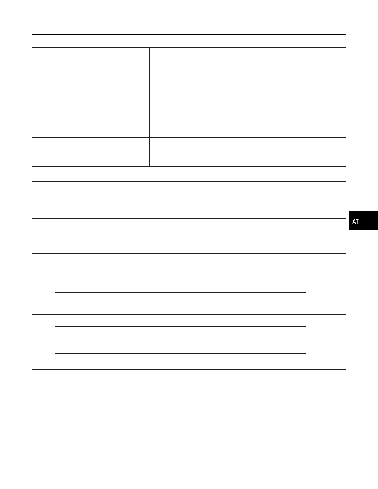
I P position
Similar to the N position, no control members operate. The parking pawl interconnected with the select
lever engages with the parking gear to mechanically hold the output shaft so that the power train is locked.
I N position
No control members operate. Power from the input shaft is not transmitted to the output shaft since the
clutch does not operate.
=NGAT0012S04
NGAT0012S0401
AT-18
SAT039J
OVERALL SYSTEM
Shift Mechanism (Cont’d)
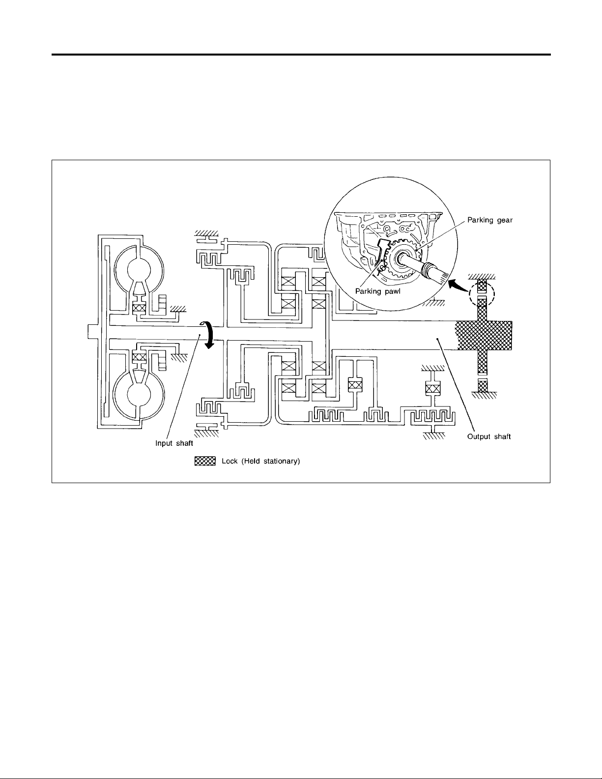
11Position
Forward clutch
Forward one-way clutch
Overrun clutch
Low and reverse brake
Engine brake Overrun clutch always engages, therefore engine brake can be obtained when decelerat-
As overrun clutch engages, rear internal gear is locked by the operation of low and
reverse brake.
This is different from that of D
ing.
and 21.
1
=NGAT0012S0406
GI
MA
EM
LC
EC
FE
CL
MT
SAT100J
TF
PD
AX
SU
BR
ST
RS
BT
HA
AT-19
SC
EL
IDX
Shift Mechanism (Cont’d)
OVERALL SYSTEM
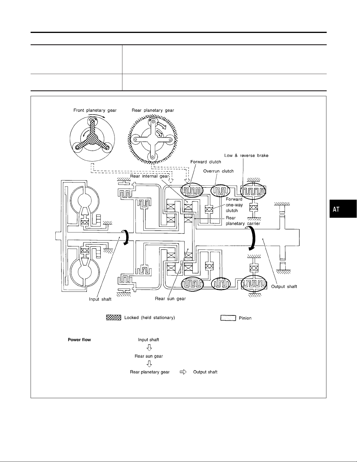
D1and 21Positions
Forward one-way clutch
Forward clutch
Low one-way clutch
Overrun clutch
engagement conditions
(Engine brake)
=NGAT0012S0402
Rear internal gear is locked to rotate counterclockwise because of the functioning of
these three clutches. (Start-up at D
D
: Overdrive control switch in OFF
1
)
1
Throttle opening less than 3/16
: Throttle opening less than 3/16
2
1
At D
and 21positions, engine brake is not activated due to free turning of low one-way
1
clutch.
AT-20
SAT096J
OVERALL SYSTEM
Shift Mechanism (Cont’d)
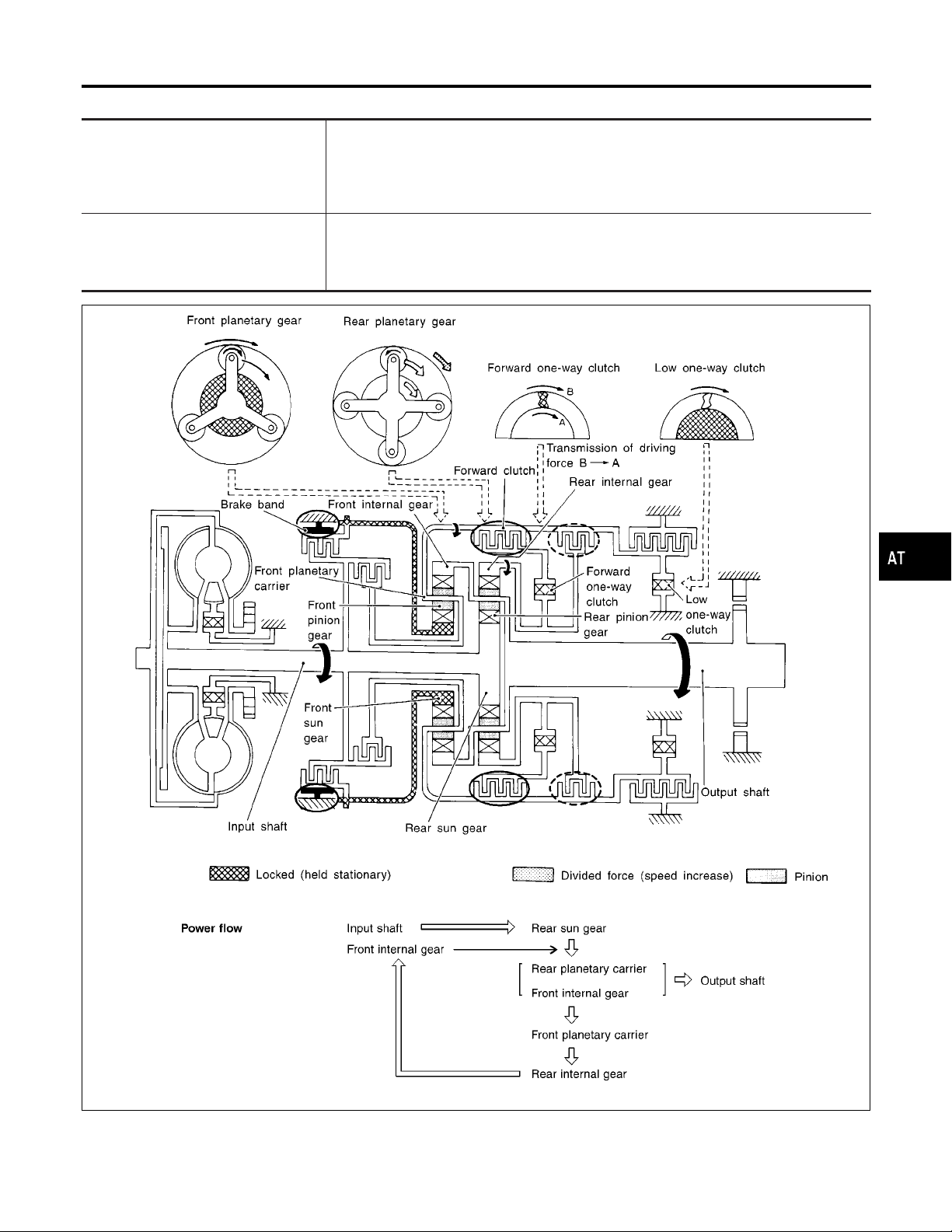
D2,22and 12Positions
Forward clutch
Forward one-way clutch
Brake band
Overrun clutch
engagement conditions
=NGAT0012S0403
Rear sun gear drives rear planetary carrier and combined front internal gear. Front internal gear now rotates around front sun gear accompanying front planetary carrier.
As front planetary carrier transfers the power to rear internal gear through forward clutch
and forward one-way clutch, this rotation of rear internal gear increases the speed of rear
planetary carrier compared with that of the 1st speed.
D
: Overdrive control switch in OFF
2
Throttle opening less than 3/16
2
: Throttle opening less than 3/16
2
1
: Always engaged
2
GI
MA
EM
LC
EC
FE
CL
MT
TF
PD
AX
SU
BR
ST
RS
BT
HA
AT-21
SC
SAT097J
EL
IDX
Shift Mechanism (Cont’d)
OVERALL SYSTEM
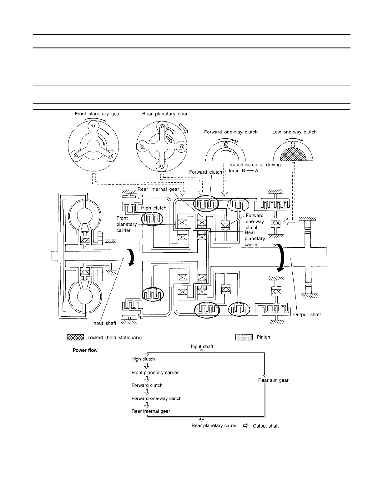
D3Position
High clutch
Forward clutch
Forward one-way clutch
Overrun clutch
engagement conditions
=NGAT0012S0404
Input power is transmitted to front planetary carrier through high clutch. And front planetary carrier is connected to rear internal gear by operation of forward clutch and forward
one-way clutch.
This rear internal gear rotation and another input (the rear sun gear) accompany rear
planetary carrier to turn at the same speed.
D
: Overdrive control switch in OFF
3
Throttle opening less than 3/16
AT-22
SAT098J
OVERALL SYSTEM
Shift Mechanism (Cont’d)
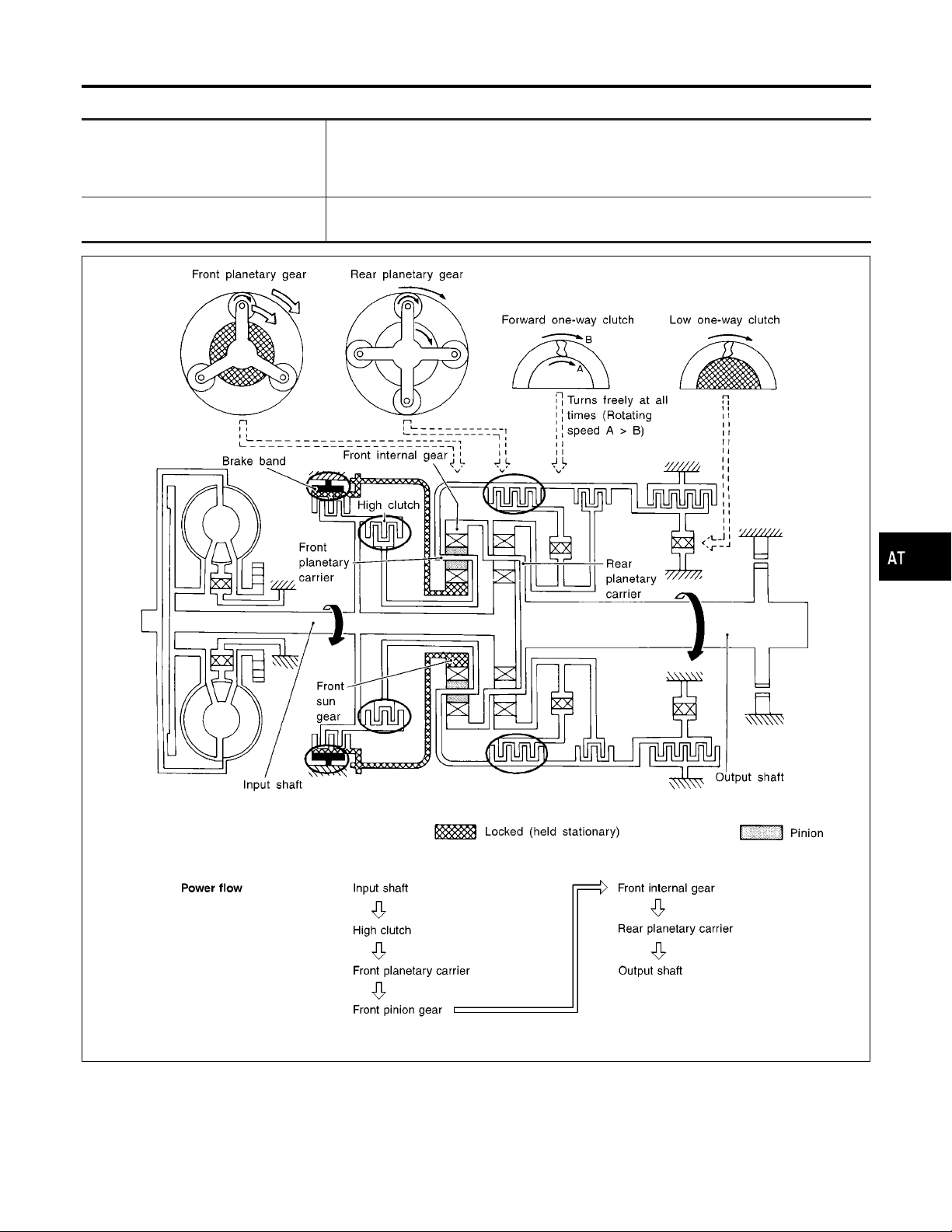
D4(O/D) Position
High clutch
Brake band
Forward clutch
(Does not affect power transmission)
Engine brake At D
=NGAT0012S0405
Input power is transmitted to front carrier through high clutch.
This front planetary carrier turns around the sun gear which is fixed by brake band and
makes front internal gear (output) turn faster.
position, there is no one-way clutch in the power transmission line and engine
4
brake can be obtained when decelerating.
GI
MA
EM
LC
EC
FE
CL
MT
SAT099J
TF
PD
AX
SU
BR
ST
RS
BT
HA
AT-23
SC
EL
IDX
Shift Mechanism (Cont’d)
OVERALL SYSTEM
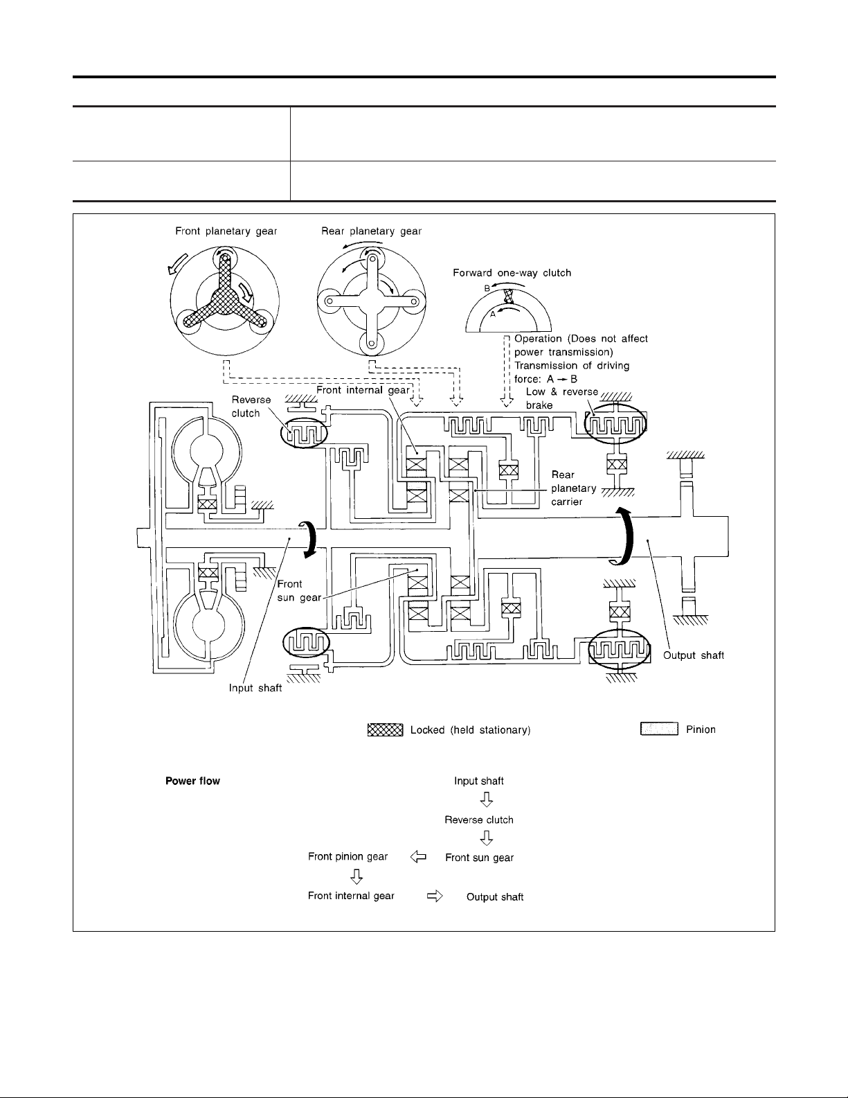
R Position
Reverse clutch
Low and reverse brake
Engine brake As there is no one-way clutch in the power transmission line, engine brake can be
Front planetary carrier is stationary because of the operation of low and reverse brake.
Input power is transmitted to front sun gear through reverse clutch, which drives front
internal gear in the opposite direction.
obtained when decelerating.
=NGAT0012S0407
AT-24
SAT101J
OVERALL SYSTEM
Control System
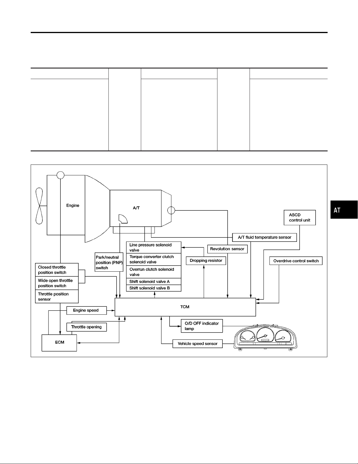
Control System
OUTLINE
=NGAT0013
NGAT0013S01
The automatic transmission senses vehicle operating conditions through various sensors. It always controls
the optimum shift position and reduces shifting and lock-up shocks.
SENSORS
PNP switch
Throttle position sensor
Closed throttle position switch
Wide open throttle position
switch
Engine speed signal
A/T fluid temperature sensor
Revolution sensor
Vehicle speed sensor
Overdrive control switch
ASCD control unit
CONTROL SYSTEM
Shift control
Line pressure control
Lock-up control
E
Overrun clutch control
Timing control
Fail-safe control
Self-diagnosis
CONSULT communication line
Duet-EU control
TCM
ACTUATORS
Shift solenoid valve A
Shift solenoid valve B
E
Overrun clutch solenoid valve
Torque converter clutch solenoid
valve
Line pressure solenoid valve
O/D OFF indicator lamp
NGAT0013S02
GI
MA
EM
LC
EC
FE
CL
MT
AAT471A
TF
PD
AX
SU
BR
ST
RS
BT
HA
AT-25
SC
EL
IDX

Control System (Cont’d)
OVERALL SYSTEM
TCM FUNCTION
The function of the TCM is to:
I Receive input signals sent from various switches and sensors.
I Determine required line pressure, shifting point, lock-up operation, and engine brake operation.
I Send required output signals to the respective solenoids.
INPUT/OUTPUT SIGNAL OF TCM
Sensors and solenoid valves Function
PNP switch Detects select lever position and sends a signal to TCM.
Throttle position sensor Detects throttle valve position and sends a signal to TCM.
Closed throttle position switch Detects throttle valve’s fully-closed position and sends a signal to TCM.
Detects a throttle valve position of greater than 1/2 of full throttle and sends
a signal to TCM.
Used as an auxiliary vehicle speed sensor. Sends a signal when revolution
sensor (installed on transmission) malfunctions.
Sends a signal, which prohibits a shift to “D
TCM.
” (overdrive) position, to the
4
Input
Wide open throttle position switch
Engine speed signal From ECM.
A/T fluid temperature sensor Detects transmission fluid temperature and sends a signal to TCM.
Revolution sensor Detects output shaft rpm and sends a signal to TCM.
Vehicle speed sensor
Overdrive control switch
=NGAT0013S03
NGAT0013S04
Output
ASCD control unit
Shift solenoid valve A/B
Line pressure solenoid valve
Torque converter clutch solenoid
valve
Overrun clutch solenoid valve
O/D OFF indicator lamp Shows TCM faults, when A/T control components malfunction.
Sends the cruise signal and “D
control unit to TCM.
Selects shifting point suited to driving conditions in relation to a signal sent
from TCM.
Regulates (or decreases) line pressure suited to driving conditions in relation
to a signal sent from TCM.
Regulates (or decreases) lock-up pressure suited to driving conditions in
relation to a signal sent from TCM.
Controls an “engine brake” effect suited to driving conditions in relation to a
signal sent from TCM.
” (overdrive) cancellation signal from ASCD
4
Control Mechanism
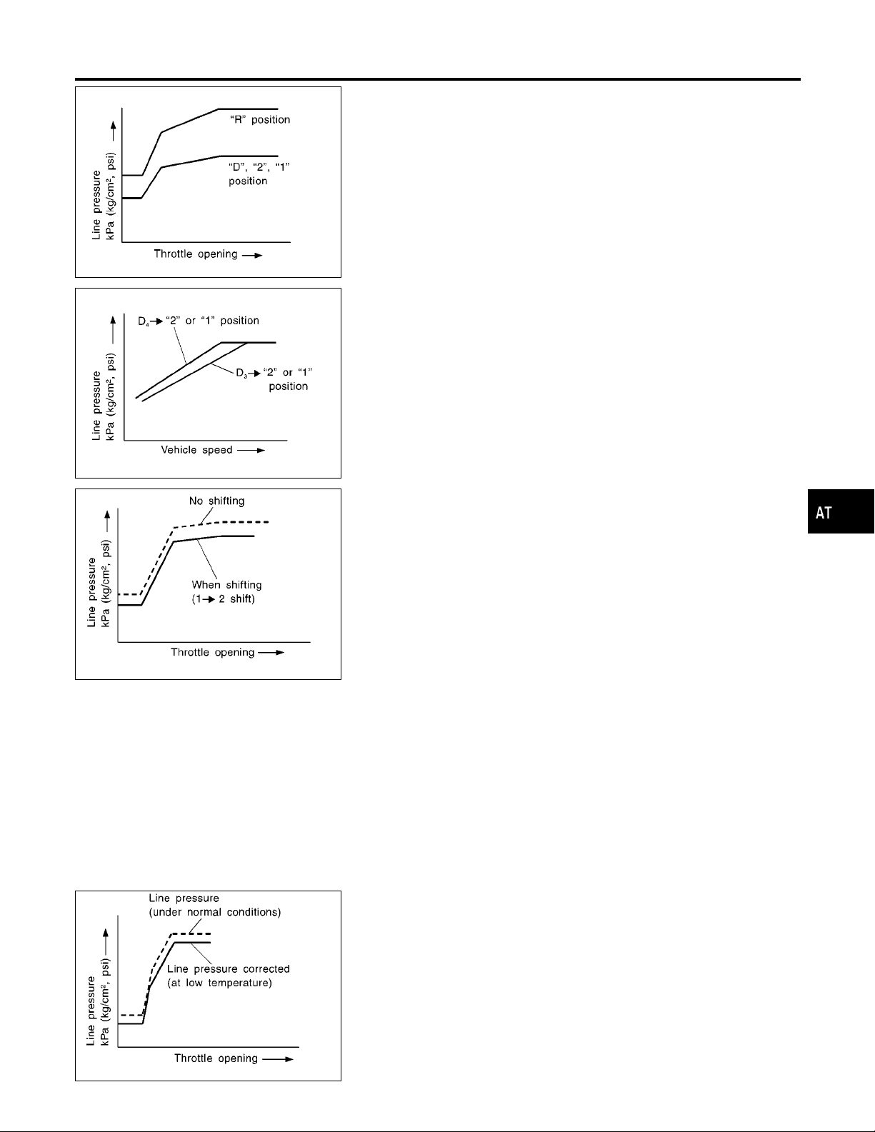
LINE PRESSURE CONTROL
TCM has the various line pressure control characteristics to meet
the driving conditions.
An ON-OFF duty signal is sent to the line pressure solenoid valve
based on TCM characteristics.
Hydraulic pressure on the clutch and brake is electronically controlled through the line pressure solenoid valve to accommodate
engine torque. This results in smooth shift operation.
NGAT0180
NGAT0180S01
AT-26
OVERALL SYSTEM
Control Mechanism (Cont’d)
SAT003J
SAT004J
Normal Control
The line pressure to throttle opening characteristics is set for suitable clutch operation.
Back-up Control (Engine brake)
If the selector lever is shifted to “2” position while driving in D4(OD)
, great driving force is applied to the clutch inside the trans-
or D
3
mission. Clutch operating pressure (line pressure) must be
increased to deal with this driving force.
During Shift Change
The line pressure is temporarily reduced corresponding to a
change in engine torque when shifting gears (that is, when the shift
solenoid valve is switched for clutch operation) to reduce shifting
shock.
NGAT0180S0101
NGAT0180S0102
NGAT0180S0103
GI
MA
EM
LC
EC
FE
CL
MT
TF
SAT005J
At Low Fluid Temperature
I Fluid viscosity and frictional characteristics of the clutch facing
change with fluid temperature. Clutch engaging or band-contacting pressure is compensated for, according to fluid
temperature, to stabilize shifting quality.
I The line pressure is reduced below 60°C (140°F) to prevent
shifting shock due to low viscosity of automatic transmission
fluid when temperature is low.
NGAT0180S0104
PD
AX
SU
BR
ST
RS
BT
HA
SC
SAT006J
EL
IDX
AT-27
Control Mechanism (Cont’d)
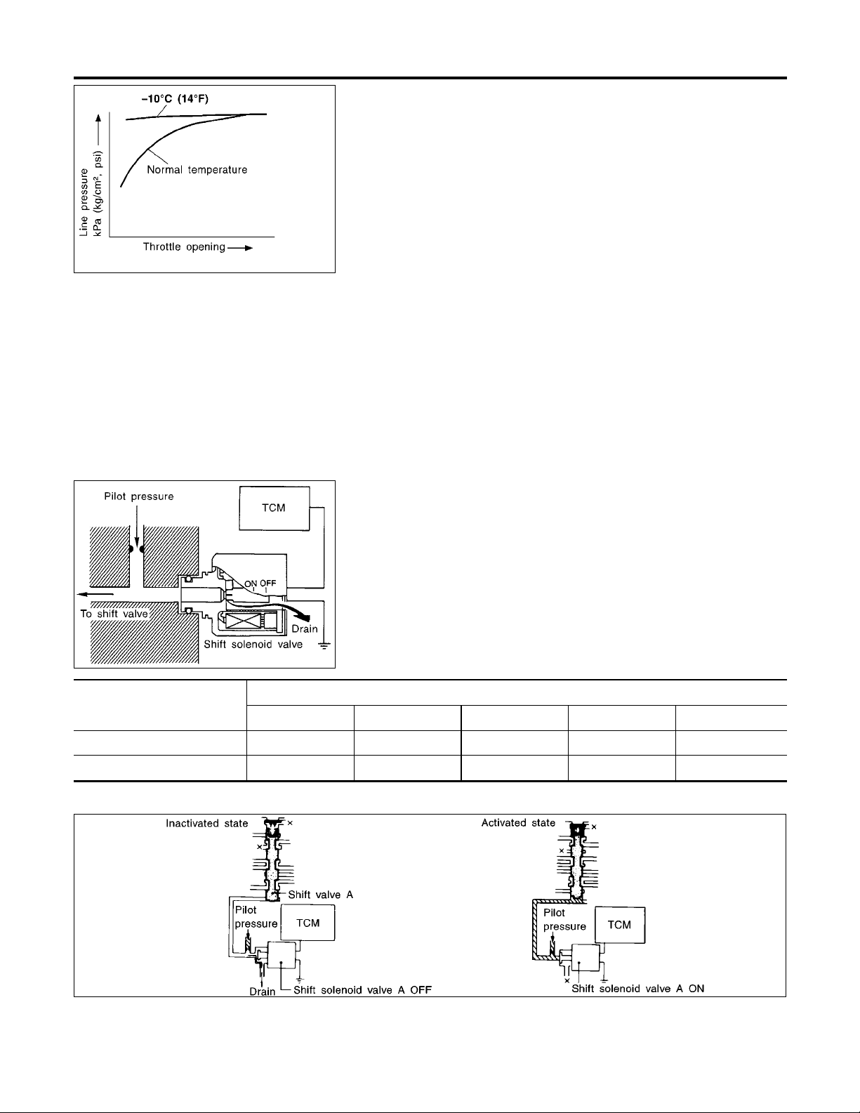
SAT007J
OVERALL SYSTEM
I Line pressure is increased to a maximum irrespective of the
throttle opening when fluid temperature drops to −10°C (14°F).
This pressure rise is adopted to prevent a delay in clutch and
brake operation due to extreme drop of fluid viscosity at low
temperature.
SHIFT CONTROL
The shift is regulated entirely by electronic control to accommodate
vehicle speed and varying engine operations. This is accomplished
by electrical signals transmitted by the revolution sensor and
throttle position sensor. This results in improved acceleration performance and fuel economy.
NGAT0180S02
Shift solenoid valve
A ON (Closed) OFF (Open) OFF (Open) ON (Closed) ON (Closed)
B ON (Closed) ON (Closed) OFF (Open) OFF (Open) ON (Closed)
SAT008J
D
1,21,11
Control of Shift Solenoid Valves A and B
NGAT0180S0201
The TCM activates shift solenoid valves A and B according to signals from the throttle position sensor and revolution sensor to
select the optimum gear position on the basis of the shift schedule
memorized in the TCM.
The shift solenoid valve performs simple ON-OFF operation. When
set to ON, the drain circuit closes and pilot pressure is applied to
the shift valve.
[Relation between shift solenoid valvesA and B and gear positions]
Gear position
D2,22,1
2
Control of Shift Valves A and B
D
3
D4(OD) N-P
NGAT0180S0202
AT-28
SAT047J
OVERALL SYSTEM
Control Mechanism (Cont’d)
Pilot pressure generated by the operation of shift solenoid valves
A and B is applied to the end face of shift valves A and B.
The drawing above shows the operation of shift valve B. When the
shift solenoid valve is “ON”, pilot pressure applied to the end face
of the shift valve overcomes spring force, moving the valve upward.
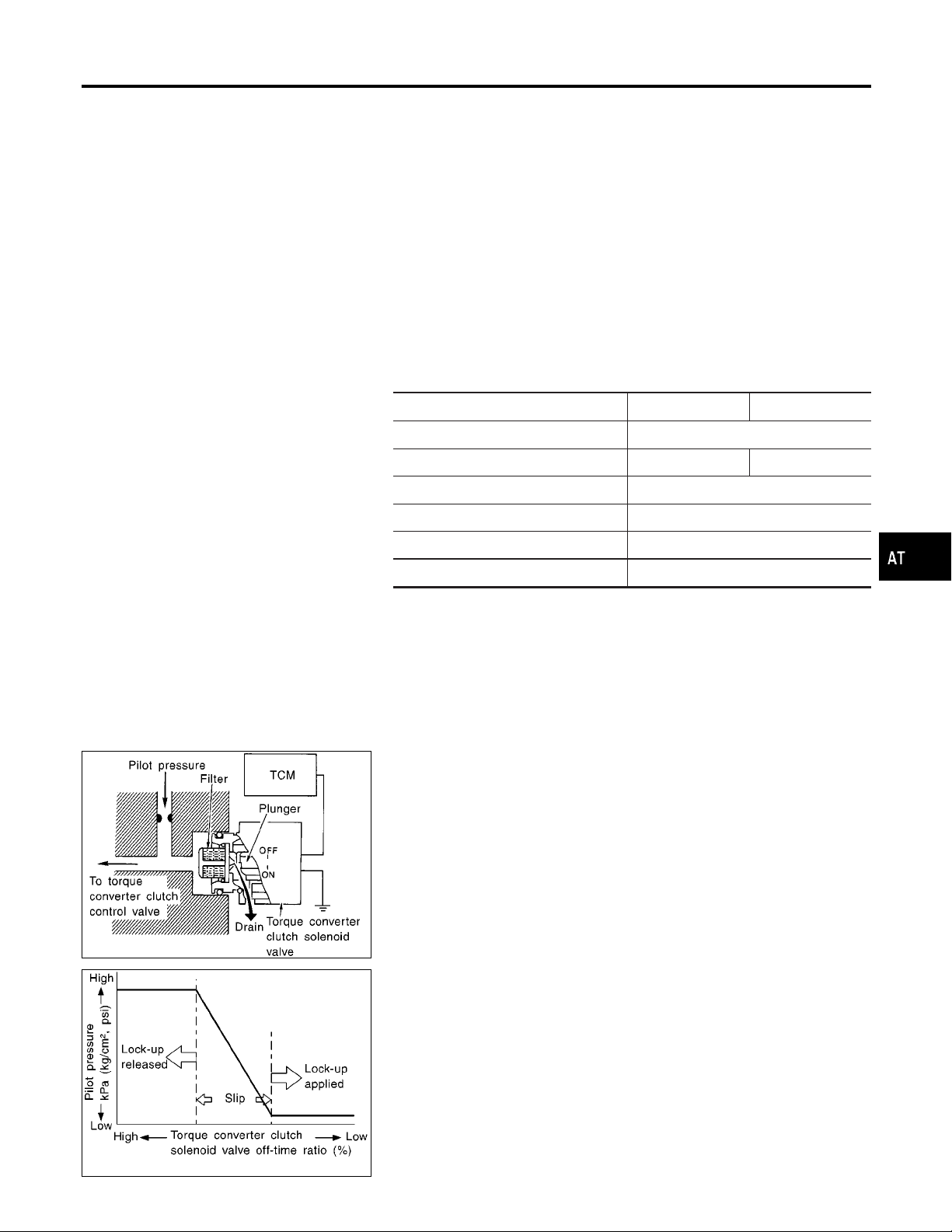
LOCK-UP CONTROL
The torque converter clutch piston in the torque converter is locked
to eliminate torque converter slip to increase power transmission
efficiency. The solenoid valve is controlled by an ON-OFF duty
signal sent from the TCM. The signal is converted to oil pressure
signal which controls the torque converter clutch piston.
Conditions for Lock-up Operation
When vehicle is driven in 4th gear position, vehicle speed and
throttle opening are detected. If the detected values fall within the
lock-up zone memorized in the TCM, lock-up is performed.
Overdrive control switch ON OFF
Selector lever “D” position
Gear position D
Vehicle speed sensor More than set value
Throttle position sensor Less than set opening
4
NGAT0180S03
NGAT0180S0301
D
3
GI
MA
EM
LC
EC
FE
CL
MT
SAT010J
Closed throttle position switch OFF
A/T fluid temperature sensor More than 40°C (104°F)
Torque Converter Clutch Solenoid Valve Control
The torque converter clutch solenoid valve is controlled by the
TCM. The plunger closes the drain circuit during the OFF period,
and opens the circuit during the ON period. If the percentage of
OFF-time increases in one cycle, the pilot pressure drain time is
reduced and pilot pressure remains high.
The torque converter clutch piston is designed to slip to adjust the
ratio of ON-OFF, thereby reducing lock-up shock.
OFF-time INCREASING
"
Amount of drain DECREASING
"
Pilot pressure HIGH
"
Lock-up RELEASING
NGAT0180S0302
TF
PD
AX
SU
BR
ST
RS
BT
HA
SC
SAT011J
EL
IDX
AT-29
Control Mechanism (Cont’d)
OVERALL SYSTEM
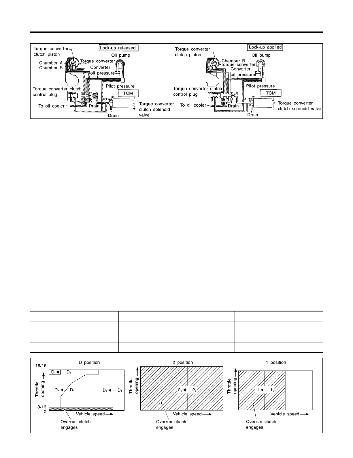
Torque Converter Clutch Control Valve Operation
NGAT0180S0303
SAT048J
Lock-up Released
The OFF-duration of the torque converter clutch solenoid valve is
long, and pilot pressure is high. The pilot pressure pushes the end
face of the torque converter clutch control valve in combination with
spring force to move the valve to the left. As a result, converter
pressure is applied to chamber A (torque converter clutch piston
release side). Accordingly, the torque converter clutch piston
remains unlocked.
Lock-up Applied
When the OFF-duration of the torque converter clutch solenoid
valve is short, pilot pressure drains and becomes low. Accordingly,
the control valve moves to the right by the pilot pressure of the
other circuit and converter pressure. As a result, converter pressure is applied to chamber B, keeping the torque converter clutch
piston applied.
Also smooth lock-up is provided by transient application and
release of the lock-up.
OVERRUN CLUTCH CONTROL (ENGINE BRAKE
CONTROL)
Forward one-way clutch is used to reduce shifting shocks in downshifting operations. This clutch transmits engine torque to the
wheels. However, drive force from the wheels is not transmitted to
the engine because the one-way clutch rotatesidle. This means the
engine brake is not effective.
The overrun clutch operates when the engine brake is needed.
Overrun Clutch Operating Conditions
D position D
2 position 2
1 position 1
Gear position Throttle opening
1,D2,D3
gear position
gear position
1,22
gear position At any position
1,12
Less than 3/16
NGAT0180S04
NGAT0180S0401
AT-30
SAT014J

OVERALL SYSTEM
Control Mechanism (Cont’d)
SAT015J
Overrun Clutch Solenoid Valve Control
NGAT0180S0402
The overrun clutch solenoid valve is operated by an ON-OFF signal transmitted by the TCM to provide overrun clutch control
(engine brake control).
When this solenoid valve is ON, the pilot pressure drain port
closes. When it is OFF, the drain port opens.
During the solenoid valve ON pilot pressure is applied to the end
face of the overrun clutch control valve.
Overrun Clutch Control Valve Operation
NGAT0180S0403
When the solenoid valve is ON, pilot pressure A is applied to the
overrun clutch control valve. This pushes up the overrun clutch
control valve. The line pressure is then shut off so that the clutch
does not engage.
When the solenoid valve is OFF, pilot pressure A is not generated.
At this point, the overrun clutch control valve moves downward by
spring force. As a result, overrun clutch operation pressure is provided by the overrun clutch reducing valve. This causes the overrun clutch to engage.
In the 1 position, the overrun clutch control valve remains pushed
down so that the overrun clutch is engaged at all times.
GI
MA
EM
LC
EC
FE
CL
MT
SAT049J
Control Valve
FUNCTION OF CONTROL VALVE
Valve name Function
I Pressure regulator valve
I Pressure regulator plug
I Pressure regulator sleeve plug
Pressure modifier valve Used as a signal supplementary valve to the pressure regulator valve. Regulates
Modifier accumulator piston Smooths hydraulic pressure regulated by the pressure modifier valve to prevent pul-
Pilot valve Regulates line pressure to maintain a constant pilot pressure level which controls
Accumulator control valve
Accumulator control sleeve
Manual valve Directs line pressure to oil circuits corresponding to select positions.
Regulate oil discharged from the oil pump to provide optimum line pressure for all
driving conditions.
pressure-modifier pressure (signal pressure) which controls optimum line pressure for
all driving conditions.
sations.
lock-up mechanism, overrun clutch, 3-2 timing required for shifting.
Regulate accumulator backpressure to pressure suited to driving conditions.
Hydraulic pressure drains when the shift lever is in Neutral.
NGAT0181S01
NGAT0181
TF
PD
AX
SU
BR
ST
RS
BT
HA
SC
EL
AT-31
IDX

OVERALL SYSTEM
Control Valve (Cont’d)
Valve name Function
Shift valve A Simultaneously switches three oil circuits using output pressure of shift solenoid valve
A to meet driving conditions (vehicle speed, throttle opening, etc.).
Provides automatic downshifting and up-shifting (1st , 2nd , 3rd , 4th gears/4th
, 3rd , 2nd , 1st gears) in combination with shift valve B.
Shift valve B Simultaneously switches three oil circuits using output pressure of shift solenoid valve
B in relation to driving conditions (vehicle speed, throttle opening, etc.).
Provides automatic downshifting and up-shifting (1st , 2nd , 3rd , 4th gears/4th
, 3rd , 2nd , 1st gears) in combination with shift valve A.
Shuttle shift valve S Switches hydraulic circuits to provide 3-2 timing control and overrun clutch control in
relation to the throttle opening.
Inactivates the overrun clutch to prevent interlocking in 4th gear when the throttle is
wide open.
Overrun clutch control valve Switches hydraulic circuits to prevent engagement of the overrun clutch simulta-
neously with application of the brake band in 4th gear. (Interlocking occurs if the
overrun clutch engages during D
4-2 relay valve Memorizes that the transmission is in 4th gear. Prevents the transmission from down-
shifting from 4th gear to 3rd and then to 2nd in combination with 4-2 sequence valve
and shift valves A and B when downshifting from 4th to 2nd gear.
4-2 sequence valve Prevents band servo pressure from draining before high clutch operating pressure
and band servo releasing pressure drain (from the same circuit) during downshifting
from 4th to 2nd gear.
gear operation.)
4
Servo charger valve An accumulator and a one-way orifice are used in the 2nd gear band servo oil circuit
to dampen shifting shock when shifting from 1st to 2nd gear.
To maintain adequate flowrate when downshifting from 4th or 3rd gear to 2nd gear,
the servo charger valve directs 2nd gear band servo hydraulic pressure to the circuit
without going through the one-way orifice when downshifting from 3rd or a higher
gear.
3-2 timing valve Prevents a late operation of the brake band when shifting selector lever from D to 1
or 2 position while driving in D
1 reducing valve Reduces low & reverse brake pressure to dampen engine-brake shock when down-
shifting from the 1 position 2nd gear to 1st gear.
Overrun clutch reducing valve Reduces oil pressure directed to the overrun clutch and prevents engine-brake shock.
In 1 and 2 positions, line pressure acts on the overrun clutch reducing valve to
increase the pressure-regulating point, with resultant engine brake capability.
Torque converter relief valve Prevents an excessive rise in torque converter pressure.
Torque converter clutch control valve,
torque converter clutch control plug and
torque converter clutch control sleeve
Shuttle shift valve D Switches hydraulic circuits so that output pressure of the torque converter clutch sole-
Activate or inactivate the lock-up function.
Also provide smooth lock-up through transient application and release of the lock-up
system.
noid valve acts on the lock-up valve in the D position of 2nd, 3rd and 4th gears. (In
the D position 1st gear, lock-up is inhibited.)
I Lock-up control is not affected in D position 2nd, 3rd or 4th gears, unless output
pressure of the torque converter clutch solenoid valve is generated by a signal
from the control unit.
.
3
AT-32

ON BOARD DIAGNOSTIC SYSTEM DESCRIPTION
Introduction
Introduction
The A/T system has two self-diagnostic systems.
The first is the emission-related on board diagnostic system (OBD-II) performed by the TCM in combination
with the ECM. The malfunction is indicated by the MIL (malfunction indicator lamp) and is stored as a DTC in
the ECM memory but not the TCM memory.
The second is the TCM original self-diagnosis indicated by the O/D OFF indicator lamp. The malfunction is
stored in the TCM memory. The detected items are overlapped with OBD-II self-diagnostic items. For detail,
refer to AT-46.
OBD-II Function for A/T System
The ECM provides emission-related on board diagnostic (OBD-II) functions for the A/T system. One function
is to receive a signal from the TCM used with OBD-related parts of the A/T system. The signal is sent to the
ECM when a malfunction occurs in the corresponding OBD-related part. The other function is to indicate a
diagnostic result by means of the MIL (malfunction indicator lamp) on the instrument panel. Sensors, switches
and solenoid valves are used as sensing elements.
The MIL automatically illuminates in One or Two Trip Detection Logic when a malfunction is sensed in relation to A/T system parts.
One or Two Trip Detection Logic of OBD-II
ONE TRIP DETECTION LOGIC
If a malfunction is sensed during the first test drive, the MIL will illuminate and the malfunction will be stored
in the ECM memory as a DTC. The TCM is not provided with such a memory function.
TWO TRIP DETECTION LOGIC
When a malfunction is sensed during the first test drive, it is stored in the ECM memory as a 1st trip DTC
(diagnostic trouble code) or 1st trip freeze frame data. At this point, the MIL will not illuminate. — First Trip
If the same malfunction as that experienced during the first test drive is sensed during the second test drive,
the MIL will illuminate. — Second Trip
A/T-related parts for which the MIL illuminates during the first or second test drive are listed below.
MIL
Items
One trip detection Two trip detection
NGAT0014
NGAT0182
NGAT0015
NGAT0015S01
NGAT0015S02
GI
MA
EM
LC
EC
FE
CL
MT
TF
PD
Shift solenoid valve A — DTC: P0750 (1108) X
Shift solenoid valve B — DTC: P0755 (1201) X
Throttle position sensor or switch — DTC: P1705 (1206) X
Except above X
The “trip” in the “One or Two Trip Detection Logic” means a driving mode in which self-diagnosis is performed
during vehicle operation.
OBD-II Diagnostic Trouble Code (DTC)
HOW TO READ DTC AND 1ST TRIP DTC
DTC and 1st trip DTC can be read by the following methods.
1. (
2. (
I 1st trip DTC No. is the same as DTC No.
I Output of the diagnostic trouble code indicates that the indicated circuit has a malfunction.
No Tools) The number of blinks of the malfunction indicator lamp in the Diagnostic Test Mode II
(Self-Diagnostic Results) Examples: 1101, 1102, 1103, 1104, etc. For details, refer to “Malfunction Indicator Lamp (MIL)”, “ON BOARD DIAGNOSTIC SYSTEM DESCRIPTION”,
These DTCs are controlled by NISSAN.
with CONSULT-II or GST) CONSULT-II or GST (Generic Scan Tool) Examples: P0705, P0710,
P0720, P0725, etc.
These DTCs are prescribed by SAE J2012.
(CONSULT-II also displays the malfunctioning component or system.)
However, in case of the Mode II and GST they do not indicate whether the malfunction is still
occurring or occurred in the past and returned to normal.
CONSULT-II can identify them as shown below. Therefore, using CONSULT-II (if available) is recommended.
EC-69
.
NGAT0016
NGAT0016S01
AT-33
AX
SU
BR
ST
RS
BT
HA
SC
EL
IDX

ON BOARD DIAGNOSTIC SYSTEM DESCRIPTION
OBD-II Diagnostic Trouble Code (DTC) (Cont’d)
A sample of CONSULT-II display for DTC is shown at left. DTC or 1st trip DTC of a malfunction is displayed
in SELF-DIAGNOSTIC RESULTS mode for “ENGINE” with CONSULT-II. Time data indicates how many times
the vehicle was driven after the last detection of a DTC.
SAT580J
If the DTC is being detected currently, the time data will be “0”.
SAT581J
If a 1st trip DTC is stored in the ECM, the time data will be “[245]”.
SAT582J
Freeze Frame Data and 1st Trip Freeze Frame Data
NGAT0016S0101
The ECM has a memory function, which stores the driving condition such as fuel system status, calculated
load value, engine coolant temperature, short term fuel trim, long term fuel trim, engine speed and vehicle
speed at the moment the ECM detects a malfunction.
Data which are stored in the ECM memory, along with the 1st trip DTC, are called 1st trip freeze frame data,
and the data, stored together with the DTC data, are called freeze frame data and displayed on CONSULT-II
or GST. The 1st trip freeze frame data can only be displayed on the CONSULT-II screen, not on the GST. For
detail, refer to “CONSULT-II”, “ON BOARD DIAGNOSTIC SYSTEM DESCRIPTION”,
EC-78
.
Only one set of freeze frame data (either 1st trip freeze frame data of freeze frame data) can be stored in the
ECM. 1st trip freeze frame data is stored in the ECM memory along with the 1st trip DTC. There is no priority for 1st trip freeze frame data and it is updated each time a different 1st trip DTC is detected. However, once
freeze frame data (2nd trip detection/MIL on) is stored in the ECM memory, 1st trip freeze frame data is no
longer stored. Remember, only one set of freeze frame data can be stored in the ECM. The ECM has the following priorities to update the data.
AT-34

ON BOARD DIAGNOSTIC SYSTEM DESCRIPTION
Priority Items
OBD-II Diagnostic Trouble Code (DTC) (Cont’d)
1 Freeze frame data Misfire — DTC: P0300 - P0306 (0701, 0603 - 0608)
Fuel Injection System Function — DTC: P0171 (0115), P0172 (0114), P0174 (0209), P0175
(0210)
2 Except the above items (Includes A/T related items)
3 1st trip freeze frame data
Both 1st trip freeze frame data and freeze frame data (along with the DTCs) are cleared when the ECM
memory is erased.
HOW TO ERASE DTC
The diagnostic trouble code can be erased by CONSULT-II, GST or ECM DIAGNOSTIC TEST MODE as
described following.
I If the battery terminal is disconnected, the diagnostic trouble code will be lost within 24 hours.
I When you erase the DTC, using CONSULT-II or GST is easier and quicker than switching the mode
selector on the ECM.
The following emission-related diagnostic information is cleared from the ECM memory when erasing DTC
related to OBD-II. For details, refer to “Emission-related Diagnostic Information”, “ON BOARD DIAGNOSTIC
SYSTEM DESCRIPTION”,
I Diagnostic trouble codes (DTC)
I 1st trip diagnostic trouble codes (1st trip DTC)
I Freeze frame data
I 1st trip freeze frame data
I System readiness test (SRT) codes
I Test values
EC-57
.
HOW TO ERASE DTC (WITH CONSULT-II)
I If a DTC is displayed for both ECM and TCM, it needs to be erased for both ECM and TCM.
1. If the ignition switch stays ON after repair work, be sure to turn ignition switch OFF once. Wait at least 5
seconds and then turn it ON (engine stopped) again.
2. Turn CONSULT-II ON and touch “A/T”.
3. Touch “SELF-DIAG RESULTS”.
4. Touch “ERASE”. (The DTC in the TCM will be erased.) Then touch “BACK” twice.
5. Touch “ENGINE”.
6. Touch “SELF-DIAG RESULTS”.
7. Touch “ERASE”. (The DTC in the ECM will be erased.)
NGAT0016S02
NGAT0016S03
GI
MA
EM
LC
EC
FE
CL
MT
TF
PD
AX
SU
BR
AT-35
ST
RS
BT
HA
SC
EL
IDX

ON BOARD DIAGNOSTIC SYSTEM DESCRIPTION
OBD-II Diagnostic Trouble Code (DTC) (Cont’d)
SAT583J
HOW TO ERASE DTC (WITH GST)
NGAT0016S04
1. If the ignition switch stays ON after repair work, be sure to turn ignition switch OFF once. Wait at least 5
seconds and then turn it ON (engine stopped) again.
2. Perform “OBD-II SELF-DIAGNOSTIC PROCEDURE (No Tools)”. Refer to AT-46. (The engine warm-up
step can be skipped when performing the diagnosis only to erase the DTC.)
3. Select Mode 4 with Generic Scan Tool (GST). For details, refer to “Generic ScanTool (GST)”, “ON BOARD
DIAGNOSTIC SYSTEM DESCRIPTION”,
HOW TO ERASE DTC (NO TOOLS)
EC-89
.
NGAT0016S05
1. If the ignition switch stays ON after repair work, be sure to turn ignition switch OFF once. Wait at least 5
seconds and then turn it ON (engine stopped) again.
2. Perform “TCM SELF-DIAGNOSTIC PROCEDURE (No Tools)”. Refer toAT-47. (The engine warm-up step
can be skipped when performing the diagnosis only to erase the DTC.)
3. Change the diagnostic test mode from Mode II to Mode I by turning the mode selector on the ECM.
Refer to “HOW TO SWITCH DIAGNOSTIC TEST MODES”, “Malfunction Indicator Lamp (MIL)”, “ON
BOARD DIAGNOSTIC SYSTEM DESCRIPTION”,
EC-71
.
AT-36

ON BOARD DIAGNOSTIC SYSTEM DESCRIPTION
Malfunction Indicator Lamp (MIL)
SAT964I
Malfunction Indicator Lamp (MIL)
1. The malfunction indicator lamp will light up when the ignition
switch is turned ON without the engine running. This is for
checking the lamp.
I If the malfunction indicator lamp does not light up, refer to
“System Description”, “WARNING LAMPS”,
(Or see MIL & Data link connector in EC section.)
2. When the engine is started, the malfunction indicator lamp
should go off.
If the lamp remains on, the on board diagnostic system has
detected an emission-related (OBD-II) malfunction. For detail,
refer to “ON BOARD DIAGNOSTIC SYSTEM DESCRIPTION”.
EL-73
CONSULT-II
After performing “SELF-DIAGNOSTIC PROCEDURE (WITH CONSULT-II)” (AT-38), place check marks for results on the “Diagnostic Worksheet”, AT-55. Reference pages are provided following the
items.
NOTICE:
1) The CONSULT-II electrically displays shift timing and lock-up
timing (that is, operation timing of each solenoid).
Check for time difference between actual shift timing and the
CONSULT-II display. If the difference is noticeable, mechanical parts (except solenoids, sensors, etc.) may be malfunctioning. Check mechanical parts using applicable diagnostic procedures.
2) Shift schedule (which implies gear position) displayed on
CONSULT-II and that indicated in Service Manual may differ
slightly. This occurs because of the following reasons:
I Actual shift schedule has more or less tolerance or allowance,
I Shift schedule indicated in Service Manual refers to the point
where shifts start, and
I Gear position displayed on CONSULT-II indicates the point
where shifts are completed.
3) Shift solenoid valve “A” or “B” is displayed on CONSULT-II at
the start of shifting. Gear position is displayed upon completion
of shifting (which is computed by TCM).
4) Additional CONSULT-II information can be found in the Operation Manual supplied with the CONSULT-II unit.
NGAT0183
.
NGAT0184
GI
MA
EM
LC
EC
FE
CL
MT
TF
PD
AX
SU
BR
ST
RS
BT
HA
AT-37
SC
EL
IDX

CONSULT-II (Cont’d)
ON BOARD DIAGNOSTIC SYSTEM DESCRIPTION
SAT580J
SAT584J
SELF-DIAGNOSTIC PROCEDURE (WITH CONSULT-II)
NGAT0184S01
1. Turn on CONSULT-II and touch “ENGINE” for OBD-II detected
items or touch “A/T” for TCM self-diagnosis.
If A/T is not displayed, check TCM power supply and ground
circuit. Refer to AT-92. If result is NG, refer to “POWER SUPPLY ROUTING”,
EL-9
.
2. Touch “SELF-DIAG RESULTS”.
Display shows malfunction experienced since the last erasing
operation.
CONSULT-II performs REAL-TIME SELF-DIAGNOSIS.
Also, any malfunction detected while in this mode will be displayed at real time.
SELF-DIAGNOSTIC RESULT TEST MODE
NGAT0184S02
Detected items
(Screen terms for CONSULT-II, “SELFDIAG RESULTS” test mode)
“A/T” “ENGINE”
PNP switch circuit I TCM does not receive the correct
—
Revolution sensor I TCM does not receive the proper
VHCL SPEED
SEN·A/T
Vehicle speed sensor (Meter) I TCM does not receive the proper
VHCL SPEED
SEN·MTR
A/T 1st gear function I A/T cannot be shifted to the 1st
—
A/T 2nd gear function I A/T cannot be shifted to the 2nd
—
PNP SW/CIRC
VEH SPD SEN/CIR
AT
—
A/T 1ST GR
FNCTN
A/T 2ND GR
FNCTN
Malfunction is detected when ...
voltage signal (based on the gear
position) from the switch.
voltage signal from the sensor.
voltage signal from the sensor.
gear position even if electrical circuit is good.
gear position even if electrical circuit is good.
TCM self-diagnosis OBD-II (DTC)
Available by
O/D OFF
indicator lamp or
“A/T” on CONSULT-II
— P0705
X P0720
X—
— P0731*1
— P0732*1
Available by
malfunction
indicator lamp*2,
“ENGINE” on CON-
SULT-II or GST
A/T 3rd gear function I A/T cannot be shifted to the 3rd
gear position even if electrical circuit is good.
—
A/T 3RD GR
FNCTN
AT-38
— P0733*1

ON BOARD DIAGNOSTIC SYSTEM DESCRIPTION
CONSULT-II (Cont’d)
Detected items
(Screen terms for CONSULT-II, “SELFDIAG RESULTS” test mode)
“A/T” “ENGINE”
A/T 4th gear function I A/T cannot be shifted to the 4th
—
A/T TCC S/V function (lock-up) I A/T cannot perform lock-up even
—
Shift solenoid valve A I TCM detects an improper voltage
SHIFT
SOLENOID/V A
Shift solenoid valve B I TCM detects an improper voltage
SHIFT
SOLENOID/V B
Overrun clutch solenoid valve I TCM detects an improper voltage
OVERRUN
CLUTCH S/V
T/C clutch solenoid valve I TCM detects an improper voltage
T/C CLUTCH
SOL/V
A/T 4TH GR
FNCTN
A/T TCC S/V
FNCTN
SFT SOL A/CIRC
SFT SOL B/CIRC
O/R CLUCH SOL/
CIRC
TCC SOLENOID/
CIRC
Malfunction is detected when ...
gear position even if electrical circuit is good.
if electrical circuit is good.
drop when it tries to operate the
solenoid valve.
drop when it tries to operate the
solenoid valve.
drop when it tries to operate the
solenoid valve.
drop when it tries to operate the
solenoid valve.
TCM self-diagnosis OBD-II (DTC)
Available by
O/D OFF
indicator lamp or
“A/T” on CONSULT-II
— P0734*1
— P0744*1
X P0750
X P0755
X P1760
X P0740
Available by
malfunction
indicator lamp*2,
“ENGINE” on CON-
SULT-II or GST
GI
MA
EM
LC
EC
FE
CL
MT
TF
PD
Line pressure solenoid valve I TCM detects an improper voltage
LINE PRESSURE
S/V
Throttle position sensor
Throttle position switch
THROTTLE POSI
SEN
Engine speed signal I TCM does not receive the proper
ENGINE SPEED SIG
A/T fluid temperature sensor I TCM receives an excessively low
BATT/FLUID TEMP
SEN
TCM (RAM) I TCM memory (RAM) is malfuncCONTROL UNIT
(RAM)
TCM (ROM) I TCM memory (ROM) is malfuncCONTROL UNIT
(ROM)
L/PRESS SOL/
CIRC
TP SEN/CIRC A/T
ATF TEMP SEN/
CIRC
—
—
drop when it tries to operate the
solenoid valve.
I TCM receives an excessively low
or high voltage from the sensor.
voltage signal from the ECM.
or high voltage from the sensor.
tioning.
tioning.
X P0745
AX
SU
X P1705
BR
X P0725
X P0710
ST
RS
BT
——
HA
——
SC
EL
AT-39
IDX

CONSULT-II (Cont’d)
ON BOARD DIAGNOSTIC SYSTEM DESCRIPTION
Detected items
(Screen terms for CONSULT-II, “SELFDIAG RESULTS” test mode)
“A/T” “ENGINE”
TCM EEPROM I TCM memory (EEPROM) is malCONTROL UNIT
(EEPROM
Initial start I This is not a malfunction message
INITIAL START
No failure
(NO SELF DIAGNOSTIC FAILURE INDICATED FURTHER TESTING MAY BE
REQUIRED**)
X: Applicable
—: Not applicable
*1: These malfunctions cannot be displayed by MIL
*2: Refer to “Malfunction Indicator Lamp (MIL)”, “ON BOARD DIAGNOSTIC SYSTEM DESCRIPTION”,
—
—
Malfunction is detected when ...
functioning.
(Whenever shutting off a power
supply to the control unit, this
message appears on the screen.)
I No failure has been detected.
if another malfunction is assigned to MIL.
TCM self-diagnosis OBD-II (DTC)
Available by
O/D OFF
indicator lamp or
“A/T” on CONSULT-II
——
X—
XX
indicator lamp*2,
“ENGINE” on CON-
SULT-II or GST
EC-69
.
Available by
malfunction
Item Display
Vehicle speed sensor 1
(A/T)
(Revolution sensor)
Vehicle speed sensor 2
(Meter)
Throttle position sensor THRTL POS
A/T fluid temperature sensor
VHCL/S SE·A/T
[km/h] or [mph]
VHCL/S SE·MTR
[km/h] or [mph]
SEN
[V]
FLUID TEMP SE
[V]
DATA MONITOR MODE (A/T)
Monitor item
ECU input
signals
X—
X—
X—
X—
Main sig-
nals
I Vehicle speed computed
I Vehicle speed computed
I Throttle position sensor
I A/T fluid temperature
I Signal voltage lowers as
Description Remarks
from signal of revolution
sensor is displayed.
from signal of vehicle
speed sensor is displayed.
signal voltage is displayed.
sensor signal voltage is
displayed.
fluid temperature rises.
NGAT0184S03
When racing engine in “N”
or “P” position with vehicle
stationary, CONSULT-II
data may not indicate 0
km/h (0 mph).
Vehicle speed display may
not be accurate under
approx. 10 km/h (6 mph). It
may not indicate 0 km/h (0
mph) when vehicle is stationary.
Battery voltage BATTERY VOLT
[V]
Engine speed ENGINE SPEED
[rpm]
X—
XX
I Source voltage of TCM is
I Engine speed, computed
AT-40
displayed.
from engine speed
signal, is displayed.
Engine speed display may
not be accurate under
approx. 800 rpm. It may not
indicate 0 rpm even when
engine is not running.

ON BOARD DIAGNOSTIC SYSTEM DESCRIPTION
Item Display
Monitor item
ECU input
signals
Main sig-
nals
CONSULT-II (Cont’d)
Description Remarks
GI
Overdrive control switch OVERDRIVE SW
[ON/OFF] X —
P/N position switch P/N POSI SW
[ON/OFF] X —
R position switch R POSITION SW
[ON/OFF] X —
D position switch D POSITION SW
[ON/OFF] X —
2 position switch 2 POSITION SW
[ON/OFF]
1 position switch 1 POSITION SW
[ON/OFF]
ASCD cruise signal ASCD·CRUISE
[ON/OFF]
ASCD O/D cut signal ASCD O/D CUT
[ON/OFF]
I ON/OFF state computed
I ON/OFF state computed
I ON/OFF state computed
I ON/OFF state computed
I ON/OFF status, com-
X—
I ON/OFF status, com-
X—
I Status of ASCD cruise
X—
I Status of ASCD O/D
X—
from signal of overdrive
control SW is displayed.
from signal of P/N position SW is displayed.
from signal of R position
SW is displayed.
from signal of D position
SW is displayed.
puted from signal of 2
position SW, is displayed.
puted from signal of 1
position SW, is displayed.
signal is displayed.
ON ... Cruising state
OFF ... Normal running
state
release signal is displayed.
ON ... O/D released
OFF ... O/D not released
I This is displayed even
when no ASCD is
mounted.
I This is displayed even
when no ASCD is
mounted.
MA
EM
LC
EC
FE
CL
MT
TF
PD
AX
Kickdown switch KICKDOWN SW
[ON/OFF] X —
Closed throttle position
switch
Wide open throttle position
switch
Gear position GEAR
Selector lever position SLCT LVR POSI
Vehicle speed VEHICLE
CLOSED
THL/SW
[ON/OFF]
W/O THRL/P-SW
[ON/OFF]
SPEED
[km/h] or [mph]
I ON/OFF status, com-
I ON/OFF status, com-
X—
I ON/OFF status, com-
X—
I Gear position data used
—X
I Selector lever position
—X
I Vehicle speed data, used
—X
AT-41
puted from signal of kickdown SW, is displayed.
puted from signal of
closed throttle position
SW, is displayed.
puted from signal of wide
open throttle position
SW, is displayed.
for computation by TCM,
is displayed.
data, used for computation by TCM, is displayed.
for computation by TCM,
is displayed.
I This is displayed even
when no kickdown switch
is equipped.
I A specific value used for
control is displayed if failsafe is activated due to
error.
SU
BR
ST
RS
BT
HA
SC
EL
IDX

CONSULT-II (Cont’d)
Item Display
ON BOARD DIAGNOSTIC SYSTEM DESCRIPTION
Monitor item
ECU input
signals
Main sig-
nals
Description Remarks
Throttle position THROTTLE
POSI
[/8]
Line pressure duty LINE PRES DTY
[%]
Torque converter clutch
solenoid valve duty
Shift solenoid valve A SHIFT S/V A
Shift solenoid valve B SHIFT S/V B
Overrun clutch solenoid
valve
TCC S/V DUTY
[%]
[ON/OFF]
[ON/OFF]
OVERRUN/C
S/V
[ON/OFF] — X
I Throttle position data,
—X
I Control value of line
—X
I Control value of torque
—X
I Control value of shift
—X
I Control value of shift
—X
I Control value of overrun
used for computation by
TCM, is displayed.
pressure solenoid valve,
computed by TCM from
each input signal, is displayed.
converter clutch solenoid
valve, computed by TCM
from each input signal, is
displayed.
solenoid valve A, computed by TCM from each
input signal, is displayed.
solenoid valve B, computed by TCM from each
input signal, is displayed.
clutch solenoid valve
computed by TCM from
each input signal is displayed.
I A specific value used for
control is displayed if failsafe is activated due to
error.
Control value of solenoid is
displayed even if solenoid
circuit is disconnected.
The “OFF” signal is displayed if solenoid circuit is
shorted.
Self-diagnosis display lamp
(O/D OFF indicator lamp)
X: Applicable
—: Not applicable
SELF-D DP LMP
[ON/OFF] — X
DTC WORK SUPPORT MODE WITH CONSULT-II
CONSULT-II Setting Procedure
1. Turn ignition switch OFF.
2. Connect CONSULT-II to Data link connector. Data link connector for CONSULT-II is located in the lower instrument panel on
driver side.
I Control status of O/D
OFF indicator lamp is
displayed.
NGAT0184S04
NGAT0184S0401
ABR847
AT-42

ON BOARD DIAGNOSTIC SYSTEM DESCRIPTION
3. Turn ignition switch ON
4. Touch “START”.
CONSULT-II (Cont’d)
GI
MA
EM
SAT586J
SAT580J
SAT587J
LC
5. Touch “A/T”.
EC
FE
CL
MT
6. Touch “DTC WORK SUPPORT”.
TF
PD
AX
7. Touch select item menu (1ST, 2ND, etc.).
SU
SAT588J
SAT589J
8. Touch “START”.
AT-43
BR
ST
RS
BT
HA
SC
EL
IDX

CONSULT-II (Cont’d)
ON BOARD DIAGNOSTIC SYSTEM DESCRIPTION
9. Perform driving test according to “DTC CONFIRMATION PROCEDURE” in “TROUBLE DIAGNOSIS FOR DTC”.
SAT590J
I When testing conditions are satisfied, CONSULT-II screen
changes from “OUT OF CONDITION” to “TESTING”.
SAT591J
SAT592J
SAT593J
10. Stop vehicle. If “NG” appears on the screen, malfunction may
exist. Go to “DIAGNOSTIC PROCEDURE”.
11. Perform test drive to check gear shift feeling in accordance
with instructions displayed.
SAT594J
AT-44

ON BOARD DIAGNOSTIC SYSTEM DESCRIPTION
12. Touch “YES” or “NO”.
CONSULT-II (Cont’d)
GI
MA
EM
SAT595J
13. CONSULT-II procedure ended.
If “NG” appears on the screen, a malfunction may exist. Go to
“DIAGNOSTIC PROCEDURE”.
SAT596J
SAT593J
DTC WORK SUPPORT MODE
DTC work support item Description Check item
NGAT0184S05
LC
EC
FE
CL
MT
TF
PD
AX
SU
1ST GR FNCTN P0731
2ND GR FNCTN P0732
3RD GR FNCTN P0733
Following items for “A/T 1st gear function (P0731)” can be confirmed.
I Self-diagnosis status (whether the diagnosis is being con-
ducted or not)
I Self-diagnosis result (OK or NG)
Following items for “A/T 2nd gear function (P0732)” can be
confirmed.
I Self-diagnosis status (whether the diagnosis is being con-
ducted or not)
I Self-diagnosis result (OK or NG)
Following items for “A/T 3rd gear function (P0733)” can be con-
firmed.
I Self-diagnosis status (whether the diagnosis is being con-
ducted or not)
I Self-diagnosis result (OK or NG)
AT-45
I Shift solenoid valve A
I Shift solenoid valve B
I Each clutch
I Hydraulic control circuit
I Shift solenoid valve B
I Each clutch
I Hydraulic control circuit
I Shift solenoid valve A
I Each clutch
I Hydraulic control circuit
BR
ST
RS
BT
HA
SC
EL
IDX

ON BOARD DIAGNOSTIC SYSTEM DESCRIPTION
CONSULT-II (Cont’d)
DTC work support item Description Check item
4TH GR FNCTN P0734
TCC S/V FNCTN P0744
Following items for “A/T 4th gear function (P0734)” can be confirmed.
I Self-diagnosis status (whether the diagnosis is being con-
ducted or not)
I Self-diagnosis result (OK or NG)
Following items for “A/T TCC S/V function (lock-up) (P0744)”
can be confirmed.
I Self-diagnosis status (whether the diagnosis is being con-
ducted or not)
I Self-diagnosis result (OK or NG)
Diagnostic Procedure Without CONSULT-II
OBD-II SELF-DIAGNOSTIC PROCEDURE (WITH GST)
Refer to “Generic Scan Tool (GST)”, “ON BOARD DIAGNOSTIC
SYSTEM DESCRIPTION”,
EC-89
.
I Shift solenoid valve A
I Shift solenoid valve B
I Overrun clutch solenoid valve
I Line pressure solenoid valve
I Each clutch
I Hydraulic control circuit
I Torque converter clutch sole-
noid valve
I Each clutch
I Hydraulic control circuit
NGAT0207
NGAT0207S01
OBD-II SELF-DIAGNOSTIC PROCEDURE (NO
TOOLS)
Refer to “Malfunction Indicator Lamp (MIL)”, “ON BOARD DIAGNOSTIC SYSTEM DESCRIPTION”,
EC-69
.
NGAT0207S02
AT-46

ON BOARD DIAGNOSTIC SYSTEM DESCRIPTION
Diagnostic Procedure Without CONSULT-II (Cont’d)
TCM SELF-DIAGNOSTIC PROCEDURE (NO TOOLS)
Preparation
1. Turn ignition switch to OFF position.
2. Connector the handy type vacuum pump to the throttle opener
and apply vacuum –25.3 kPa (–190 mmHg, –7.48 inHg).
3. Disconnect the throttle position switch harness connector.
4. Turn the ignition switch to ON position.
SEF793W
5. Check continuity of the closed throttle position switch.
Continuity should exist.
(If continuity does not exist, check throttle opener and
closed throttle position switch. Then increase vacuum
until closed throttle position switch shows continuity.)
6. Go to “TCM Self-diagnostic Procedure”, AT-47.
AAT498A
1 CHECK O/D OFF INDICATOR LAMP
1. Selector lever in P position. Start the engine. Warm engine to normal operating temperature.
2. Turn ignition switch to OFF position.
3. Wait at least 5 seconds.
NGAT0207S03
NGAT0207S0301
GI
MA
EM
LC
EC
FE
CL
MT
TF
4. Turn ignition switch to ON position.
(Do not start engine.)
5. Does O/D OFF indicator lamp come on for about 2 seconds?
YesorNo
Yes © GO TO 2.
No © Go to “1. O/D OFF Indicator Lamp Does Not Come On”, AT-206.
SAT967I
AAT612A
PD
AX
SU
BR
ST
RS
BT
HA
SC
EL
AT-47
IDX

ON BOARD DIAGNOSTIC SYSTEM DESCRIPTION
Diagnostic Procedure Without CONSULT-II (Cont’d)
2 JUDGEMENT PROCEDURE STEP 1
1. Turn ignition switch to OFF position.
2. Turn ignition switch to ACC position.
3. Move selector lever from P to D position.
4. Turn ignition switch to ON position. Do not start engine.
5. Depress and hold overdrive control switch in OFF position (the O/D OFF indicator lamp will be ON) until directed to
release the switch (If O/D OFF indicator lamp does not come on, go to step 3 on AT-243).
6. Turn ignition switch to OFF position.
7. Turn ignition switch to ON position (Do not start engine).
8. Release the overdrive control switch (the O/D OFF indicator lamp will be OFF).
I Wait for more than 2 seconds after ignition switch ON.
9. Move selector lever to 2 position.
10. Depress and release the overdrive control switch (the O/D OFF indicator lamp will be ON).
11. Depress and hold the overdrive control switch (the O/D OFF indicator lamp will be OFF) until directed to release the
switch.
SAT968I
© GO TO 3.
SAT969I
AT-48

ON BOARD DIAGNOSTIC SYSTEM DESCRIPTION
Diagnostic Procedure Without CONSULT-II (Cont’d)
3 JUDGEMENT PROCEDURE STEP 2
1. Move selector lever to 1 position.
2. Release the overdrive control switch.
3. Depress and release the overdrive control switch (the O/D OFF indicator lamp will be ON).
4. Depress and release the overdrive control switch (the O/D OFF indicator lamp will be OFF).
5. Depress and hold the overdrive control switch (the O/D OFF indicator lamp will be ON) until directed to release the
switch.
6. Depress accelerator pedal fully and release.
7. Release the overdrive control switch (the O/D OFF indicator lamp will begin to flash ON and OFF).
GI
MA
EM
LC
EC
FE
SAT970I
CL
© GO TO 4.
4 CHECK SELF-DIAGNOSIS CODE
Check O/D OFF indicator lamp.
Refer to JUDGEMENT OF SELF-DIAGNOSIS CODE, AT-50.
MT
TF
PD
SAT981F
AX
SU
BR
ST
RS
© DIAGNOSIS END
AT-49
AAT612A
BT
HA
SC
EL
IDX

ON BOARD DIAGNOSTIC SYSTEM DESCRIPTION
Diagnostic Procedure Without CONSULT-II (Cont’d)
JUDGEMENT OF SELF-DIAGNOSIS CODE
O/D OFF indicator lamp:
All judgement flickers are same.
All circuits that can be confirmed by self-diagnosis are OK.
2nd judgement flicker is longer than others.
SAT436F
NGAT0207S04
1st judgement flicker is longer than others.
SAT437F
Revolution sensor circuit is short-circuited or disconnected.
⇒ Go to VEHICLE SPEED SENSOR·A/T (REVOLUTION SENSOR) , AT-111.
3rd judgement flicker is longer than others.
SAT439F
Vehicle speed sensor circuit is short-circuited or disconnected.
⇒ Go to VEHICLE SPEED SENSOR·MTR, AT-195.
4th judgement flicker is longer than others.
SAT443F
Shift solenoid valve A circuit is short-circuited or disconnected.
⇒ Go to SHIFT SOLENOID VALVEA,AT-165.
SAT441F
Throttle position sensor circuit is short-circuited or disconnected.
⇒ Go to THROTTLE POSITION SENSOR , AT-175.
5th judgement flicker is longer than others.
SAT445F
Shift solenoid valve B circuit is short-circuited or disconnected.
⇒ Go to SHIFT SOLENOID VALVE B , AT-170.
AT-50

ON BOARD DIAGNOSTIC SYSTEM DESCRIPTION
Diagnostic Procedure Without CONSULT-II (Cont’d)
O/D OFF indicator lamp:
6th judgement flicker is longer than others.
SAT447F
Overrun clutch solenoid valve circuit is short-circuited or disconnected.
⇒ Go to OVERRUN CLUTCH SOLENOID VALVE (DTC:
1203), AT-184.
8th judgement flicker is longer than others.
7th judgement flicker is longer than others.
SAT449F
Torque converter clutch solenoid valve circuit is short-circuited
or disconnected.
⇒ Go to TORQUE CONVERTER CLUTCH SOLENOID VALVE
, AT-147.
9th judgement flicker is longer than others.
GI
MA
EM
LC
EC
FE
CL
MT
SAT451F
A/T fluid temperature sensor is disconnected or TCM power
source circuit is damaged.
⇒ Go to A/T FLUID TEMPERATURE SENSOR AND TCM
POWER SOURCE, AT-189.
10th judgement flicker is longer than others.
SAT455F
Line pressure solenoid valve circuit is short-circuited or disconnected.
⇒ Go to LINE PRESSURE SOLENOID VALVE , AT-160.
SAT453F
Engine speed signal circuit is short-circuited or disconnected.
⇒ Go to ENGINE SPEED SIGNAL AT-116.
Flickers as shown below.
SAT457F
Battery power is low.
Battery has been disconnected for a long time.
Battery is connected conversely.
(When reconnecting TCM connectors. — This is not a problem.)
TF
PD
AX
SU
BR
ST
RS
BT
HA
AT-51
SC
EL
IDX

ON BOARD DIAGNOSTIC SYSTEM DESCRIPTION
Diagnostic Procedure Without CONSULT-II (Cont’d)
O/D OFF indicator lamp:
Lamp comes on.
SAT367J
PNP switch, overdrive control switch or throttle position switch
circuit is disconnected or TCM is damaged.
⇒ Go to 21. TCM Self-diagnosis Does Not Activate PNP,
OVERDRIVE CONTROL AND THROTTLE POSITION
SWITCHES), AT-243.
t
= 2.5 seconds t2= 2.0 seconds t3= 1.0 second t4= 1.0 second
1
AT-52
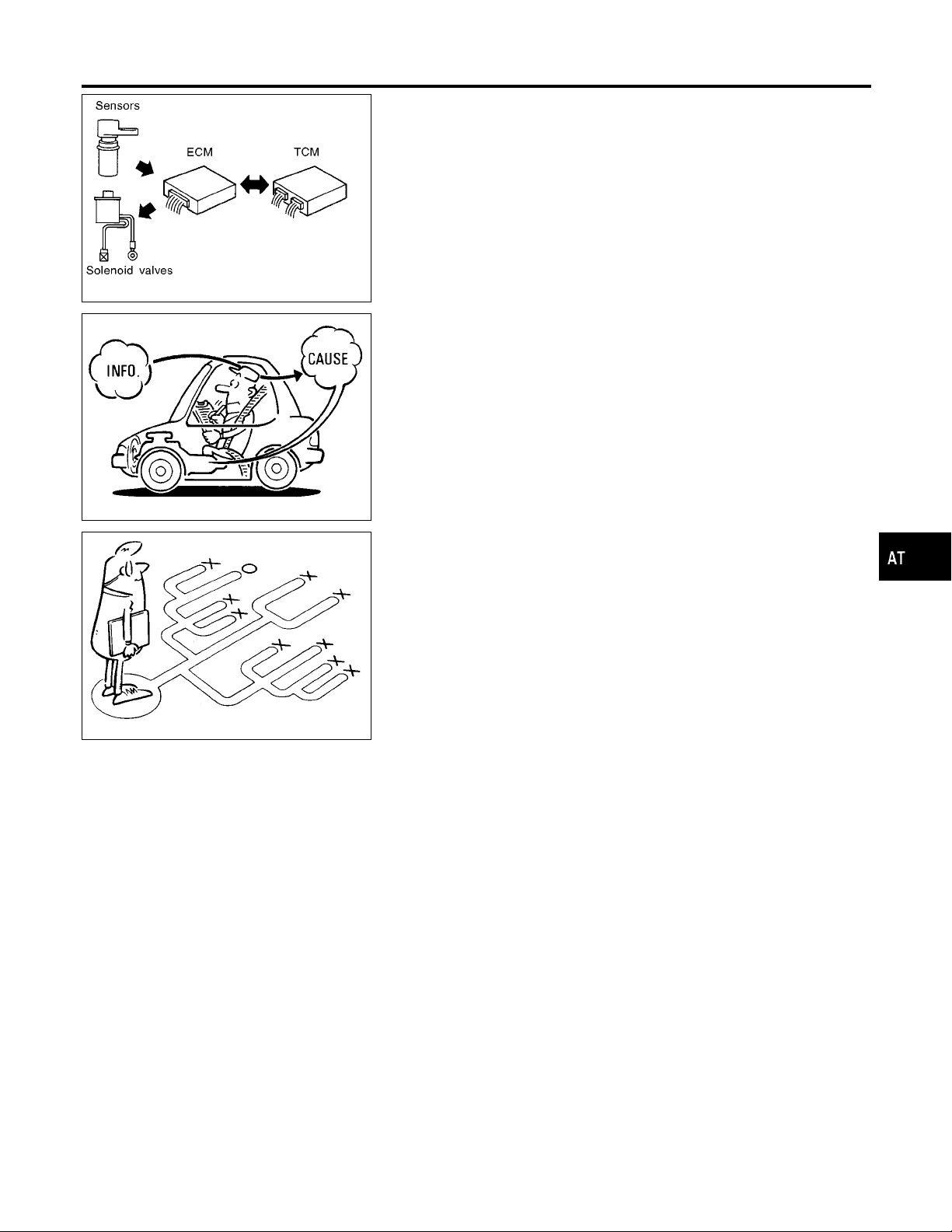
TROUBLE DIAGNOSIS — INTRODUCTION
AAT473A
SAT632I
Introduction
The TCM receives a signal from the vehicle speed sensor, throttle
position sensor or PNP switch and provides shift control or lock-up
control via A/T solenoid valves.
The TCM also communicates with the ECM by means of a signal
sent from sensing elements used with the OBD-related parts of the
A/T system for malfunction-diagnostic purposes. The TCM is
capable of diagnosing malfunctioning parts while the ECM can
store malfunctions in its memory.
Input and output signals must always be correct and stable in the
operation of the A/T system. The A/T system must be in good
operating condition and be free of valve seizure, solenoid valve
malfunction, etc.
It is much more difficult to diagnose a problem that occurs intermittently rather than continuously. Most intermittent problems are
caused by poor electric connections or improper wiring. In this
case, careful checking of suspected circuits may help prevent the
replacement of good parts.
A visual check only may not find the cause of the problems. A road
test with CONSULT-II (or GST) or a circuit tester connected should
be performed. Follow the “Work Flow”. Refer to AT-57.
Before undertaking actual checks, take a few minutes to talk with
a customer who approaches with a driveability complaint. The customer can supply good information about such problems, especially intermittent ones. Find out what symptoms are present and
under what conditions they occur.A“Diagnostic Worksheet” like the
example (AT-55) should be used.
Start your diagnosis by looking for “conventional” problems first.
This will help troubleshoot driveability problems on an electronically
controlled engine vehicle.
Also check related Service bulletins.
NGAT0019
GI
MA
EM
LC
EC
FE
CL
MT
TF
PD
SEF234G
AX
SU
BR
ST
RS
BT
HA
SC
EL
AT-53
IDX

Introduction (Cont’d)
TROUBLE DIAGNOSIS — INTRODUCTION
DIAGNOSTIC WORKSHEET
Information From Customer
KEY POINTS
WHAT ..... Vehicle & A/T model
WHEN..... Date, Frequencies
WHERE..... Road conditions
HOW..... Operating conditions, Symptoms
Customer name MR/MS Model & Year VIN
Trans. model Engine Mileage
Incident Date Manuf. Date In Service Date
Frequency l Continuous l Intermittent ( times a day)
Symptoms l Vehicle does not move. (l Any position l Particular position)
l No up-shift (l 1st , 2nd l 2nd , 3rd l 3rd , O/D)
l No down-shift (l O/D , 3rd l 3rd , 2nd l 2nd , 1st)
l Lockup malfunction
l Shift point too high or too low.
l Shift shock or slip (l N , D l Lockup l Any drive position)
l Noise or vibration
=NGAT0019S01
NGAT0019S0101
l No kickdown
l No pattern select
l Others
()
O/D OFF indicator lamp Blinks for about 8 seconds.
l Continuously lit l Not lit
Malfunction indicator lamp (MIL) l Continuously lit l Not lit
AT-54

TROUBLE DIAGNOSIS — INTRODUCTION
Introduction (Cont’d)
Diagnostic Worksheet
1. l Read the Fail-safe Remarks and listen to customer complaints. AT-8
2. l CHECK A/T FLUID AT-59
l Leakage (Follow specified procedure)
l Fluid condition
l Fluid level
3. Perform STALL TEST and LINE PRESSURE TEST. AT-59, AT-62
l Stall test — Mark possible damaged components/others.
l Torque converter one-way clutch
l Reverse clutch
l Forward clutch
l Overrun clutch
l Forward one-way clutch
l Line pressure test — Suspected parts:
4. l Perform all ROAD TEST and mark required procedures. AT-63
4-1. Check before engine is started. AT-64
l SELF-DIAGNOSTIC PROCEDURE - Mark detected items.
l PNP switch, AT-99.
l A/T fluid temperature sensor, AT-105.
l Vehicle speed sensor·A/T (Revolution sensor), AT-111.
l Engine speed signal, AT-116.
l Torque converter clutch solenoid valve, AT-147.
l Line pressure solenoid valve, AT-160.
l Shift solenoid valve A, AT-165.
l Shift solenoid valve B, AT-170.
l Throttle position sensor,AT-175.
l Overrun clutch solenoid valve, AT-184.
l A/T fluid temperature sensor and TCM power source, AT-189.
l PNP, overdrive control and throttle position switches, AT-243.
l Vehicle speed sensor·MTR, AT-195.
l Battery
l Others
4-2. Check at idle AT-66
l Low & reverse brake
l Low one-way clutch
l Engine
l Line pressure is low
l Clutches and brakes except high clutch and
brake band are OK
=NGAT0019S0102
GI
MA
EM
LC
EC
FE
CL
MT
TF
PD
AX
SU
l 1. O/D OFF Indicator Lamp Does Not Come On, AT-206.
l 2. Engine Cannot Be Started In P And N Position, AT-208.
l 3. In P Position, Vehicle Moves Forward Or Backward When Pushed, AT-209.
l 4. In N Position, Vehicle Moves, AT-210.
l 5. Large Shock. N , R Position, AT-212.
l 6. Vehicle Does Not Creep Backward In R Position, AT-214.
l 7. Vehicle Does Not Creep Forward In D, 2 Or 1 Position, AT-217.
AT-55
BR
ST
RS
BT
HA
SC
EL
IDX

TROUBLE DIAGNOSIS — INTRODUCTION
Introduction (Cont’d)
4. 4-3. Cruise test AT-67
Part-1
AT-71
l 8. Vehicle Cannot Be Started From D
l 9. A/T Does Not Shift: D
l 10. A/T Does Not Shift: D
l 11. A/T Does Not Shift: D
, D2Or Does Not Kickdown: D4, D2, AT-223.
1
2,D3
3,D4
1
, AT-226.
, AT-229.
, AT-220.
l 12. A/T Does Not Perform Lock-up, AT-232.
l 13. A/T Does Not Hold Lock-up Condition, AT-234.
l 14. Lock-up Is Not Released, AT-236.
l 15. Engine Speed Does Not Return To Idle (Light Braking D
, D3), AT-237.
4
Part-2 AT-75
l 9. A/T Does Not Shift: D
l 10. A/T Does Not Shift: D
l 11. A/T Does Not Shift: D
l 16. Vehicle Does Not Start From D
, D2Or Does Not Kickdown: D4, D2, AT-223.
1
, AT-226.
2,D3
, AT-229.
3,D4
, AT-239.
1
Part-3 AT-77
l 17. A/T Does Not Shift: D
l 15. Engine Speed Does Not Return To Idle (Engine Brake In D
l 18. A/T Does Not Shift: D
l 15. Engine Speed Does Not Return To Idle (Engine Brake In 2
l 19. A/T Does Not Shift: 2
When Overdrive Control Switch ON , OFF, AT-240
4,D3
, When Selector Lever D , 2 Position, AT-241.
3,22
, When Selector Lever 2 , 1 Position, AT-242.
2,11
), AT-237.
3
), AT-237.
2
l 20. Vehicle Does Not Decelerate By Engine Brake, AT-243.
l SELF-DIAGNOSTIC PROCEDURE — Mark detected items.
l PNP switch, AT-99.
l A/T fluid temperature sensor, AT-105.
l Vehicle speed sensor·A/T (Revolution sensor), AT-111.
l Engine speed signal, AT-116.
l Torque converter clutch solenoid valve, AT-147.
l Line pressure solenoid valve, AT-160.
l Shift solenoid valve A, AT-165.
l Shift solenoid valve B, AT-170.
l Throttle position sensor,AT-175.
l Overrun clutch solenoid valve, AT-184.
l A/T fluid temperature sensor and TCM power source, AT-189.
l PNP, overdrive control and throttle position switches, AT-243.
l Vehicle speed sensor·MTR, AT-195.
l Battery
l Others
5. l For self-diagnosis NG items, inspect each component. Repair or replace the damaged parts. AT-38
6. l Perform all ROAD TEST and re-mark required procedures. AT-63
7. l Perform DTC CONFIRMATION PROCEDURE for following MIL indicating items and check out NG items.
EC section
Refer to “Emission-related Diagnostic Information”, “ON BOARD DIAGNOSTIC SYSTEM DESCRIPTION”,
EC-66
.
l DTC (P0731, 1103) A/T 1st gear function, AT-120.
l DTC (P0732, 1104) A/T 2nd gear function, AT-126.
l DTC (P0733, 1105) A/T 3rd gear function, AT-132.
l DTC (P0734, 1106) A/T 4th gear function, AT-138.
l DTC (P0744, 1107) A/T TCC S/V function (lock-up), AT-152.
8. l Perform the Diagnostic Procedures for all remaining items marked NG. Repair or replace the damaged
parts.
AT-92
AT-81
Refer to the Symptom Chart when you perform the procedures. (The chart also shows some other possible
symptoms and the component inspection orders.)
9. l Erase DTC from TCM and ECM memories. AT-35
AT-56

TROUBLE DIAGNOSIS — INTRODUCTION
Work Flow
Work Flow
HOW TO PERFORM TROUBLE DIAGNOSES FOR QUICK AND ACCURATE REPAIR
A good understanding of the malfunction conditions can make troubleshooting faster and more accurate.
In general, each customer feels differently about a problem. It is important to fully understand the symptoms
or conditions for a customer complaint.
Make good use of the two sheets provided, “INFORMATION FROM CUSTOMER” (AT-54) and “DIAGNOSTIC WORKSHEET” (AT-55), to perform the best troubleshooting possible.
NGAT0020
NGAT0020S01
GI
MA
EM
LC
EC
FE
CL
MT
TF
PD
AX
SU
BR
ST
RS
BT
HA
AT-57
SC
EL
IDX

Work Flow (Cont’d)
TROUBLE DIAGNOSIS — INTRODUCTION
WORK FLOW CHART
NGAT0020S02
*1: AT-54
*2: AT-55
*3: AT-8
*4: AT-59
*5: AT-59, 62
*6: AT-63
*7: AT-37
*8: AT-33
*9: AT-50
*10: AT-99
*11: AT-195
*12: AT-203
AAT550A
*13: AT-243
*14: AT-81
*15: AT-35
*16: AT-100
*17: AT-195
AT-58

TROUBLE DIAGNOSIS — BASIC INSPECTION
A/T Fluid Check
SAT638A
A/T Fluid Check
FLUID LEAKAGE CHECK
1. Clean area suspected of leaking. — for example, mating surface of converter housing and transmission case.
2. Start engine, apply foot brake, place selector lever in D position and wait a few minutes.
3. Stop engine.
4. Check for fresh leakage.
FLUID CONDITION CHECK
Fluid color Suspected problem
Dark or black with burned odor Wear of frictional material
Milky pink
Varnished fluid, light to dark brown
and tacky
FLUID LEVEL CHECK
Refer to MA section (“Checking A/T Fluid”, “CHASSIS AND BODY
MAINTENANCE”).
Water contamination — Road water
entering through filler tube or breather
Oxidation — Over or under filling, —
Overheating
NGAT0021
NGAT0021S01
NGAT0021S02
NGAT0021S03
GI
MA
EM
LC
EC
FE
CL
MT
SAT647B
Stall Test
STALL TEST PROCEDURE
1. Check A/T fluid and engine oil levels. If necessary, add fluid
and oil.
2. Drive vehicle for approx. 10 minutes or until engine oil andATF
reach operating temperature.
ATF operating temperature:
50 - 80°C (122 - 176°F)
3. Set parking brake and block wheels.
4. Install a tachometer where it can be seen by driver during test.
I It is good practice to put a mark on point of specified
engine rpm on indicator.
NGAT0022
NGAT0022S01
TF
PD
AX
SU
BR
ST
RS
BT
HA
SAT513G
SC
EL
IDX
AT-59

Stall Test (Cont’d)
TROUBLE DIAGNOSIS — BASIC INSPECTION
5. Start engine, apply foot brake, and place selector lever in D
position.
6. Accelerate to wide open throttle gradually while applying foot
brake.
7. Quickly note the engine stall revolution and immediately
release throttle.
I During test, never hold throttle wide open for more than 5
seconds.
Stall revolution:
2,440 - 2,640 rpm
SAT514G
8. Move selector lever to N position.
9. Cool off ATF.
I Run engine at idle for at least one minute.
10. Repeat steps 5 through 9 with selector lever in 2, 1 and R
positions.
SAT771B
JUDGEMENT OF STALL TEST
NGAT0022S02
The test result and possible damaged components relating to each
result are shown in the illustration. In order to pinpoint the possible
damaged components, follow the WORK FLOW shown in AT-57.
NOTE:
Stall revolution is too high in D or 2 position:
I Slippage occurs in 1st gear but not in 2nd and 3rd gears. .....
Low one-way clutch slippage
I Slippage occurs at the following gears:
1st through 3rd gears in D position and engine brake functions.
1st and 2nd gears in 2 position and engine brake functions with
accelerator pedal released (fully closed throttle). ..... Forward
clutch or forward one-way clutch slippage
Stall revolution is too high in R position:
I Engine brake does not function in 1 position. ..... Low & reverse
brake slippage
I Engine brake functions in 1 position. ..... Reverse clutch slip-
page
Stall revolution within specifications:
I Vehicle does not achieve speed of more than 80 km/h (50
MPH). ..... One-way clutch seizure in torque converter housing
CAUTION:
Be careful since automatic fluid temperature increases abnormally.
I Slippage occurs in 3rd and 4th gears in D position. ..... High
clutch slippage
I Slippage occurs in 2nd and 4th gear in D position. ..... Brake
band slippage
Stall revolution less than specifications:
I Poor acceleration during starts. ..... One-way clutch seizure in
torque converter
AT-60

TROUBLE DIAGNOSIS — BASIC INSPECTION
Stall Test (Cont’d)
GI
MA
EM
LC
EC
FE
CL
MT
TF
PD
AX
SU
BR
ST
RS
AT-61
BT
HA
SC
SAT392H
EL
IDX

Line Pressure Test
TROUBLE DIAGNOSIS — BASIC INSPECTION
SAT209GA
SAT647B
Line Pressure Test
LINE PRESSURE TEST PORTS
NGAT0023
NGAT0023S03
I Location of line pressure test ports.
I Always replace line pressure plugs as they are self-seal-
ing bolts.
LINE PRESSURE TEST PROCEDURE
NGAT0023S01
1. Check A/T fluid and engine oil levels. If necessary, add fluid
and oil.
2. Drive vehicle for approx. 10 minutes or until engine oil andATF
reach operating temperature.
ATF operating temperature:
50 - 80°C (122 - 176°F)
3. Install pressure gauge to corresponding line pressure port.
SAT518GB
SAT519GB
SAT513G
4. Set parking brake and block wheels.
I Continue to depress brake pedal fully while line pressure
test is being performed at stall speed.
AT-62

TROUBLE DIAGNOSIS — BASIC INSPECTION
5. Start engine and measure line pressure at idle and stall speed.
I When measuring line pressure at stall speed, follow the
stall test procedure.
Line pressure:
Refer to SDS, AT-338.
Line Pressure Test (Cont’d)
GI
MA
EM
At idle
At stall speed
SAT493G
JUDGEMENT OF LINE PRESSURE TEST
Judgement Suspected parts
Line pressure is low in all positions.
Line pressure is low in particular
position.
Line pressure is high. I Maladjustment of throttle position sensor
Line pressure is low. I Maladjustment of throttle position sensor
I Oil pump wear
I Control piston damage
I Pressure regulator valve or plug sticking
I Spring for pressure regulator valve damaged
I Fluid pressure leakage between oil strainer and pressure regulator valve
I Clogged strainer
I Fluid pressure leakage between manual valve and particular clutch
I For example, line pressure is:
— Low in R and 1 positions, but
— Normal in D and 2 positions.
Then, fluid leakage exists at or around low and reverse brake circuit.
Refer to “CLUTCH AND BAND CHART”, AT-17.
I Fluid temperature sensor damaged
I Line pressure solenoid valve sticking
I Short circuit of line pressure solenoid valve circuit
I Pressure modifier valve sticking
I Pressure regulator valve or plug sticking
I Open in dropping resistor circuit
I Line pressure solenoid valve sticking
I Short circuit of line pressure solenoid valve circuit
I Pressure regulator valve or plug sticking
I Pressure modifier valve sticking
I Pilot valve sticking
LC
NGAT0023S02
EC
FE
CL
MT
TF
PD
AX
SU
BR
SAT786A
Road Test
DESCRIPTION
NGAT0024
NGAT0024S01
I The purpose of this test is to determine overall performance of
the A/T and analyze causes of problems.
I The road test consists of the following three parts:
a) Check before engine is started
b) Check at idle
c) Cruise test
AT-63
ST
RS
BT
HA
SC
EL
IDX

TROUBLE DIAGNOSIS — BASIC INSPECTION
Road Test (Cont’d)
SAT496G
1 CHECK O/D OFF INDICATOR LAMP
1. Park vehicle on flat surface.
2. Move selector lever to P position.
3. Turn ignition switch to OFF position.
Wait at least 5 seconds.
I Before road test, familiarize yourself with all test procedures
and items to check.
I Conduct tests on all items until specified symptom is found.
Troubleshoot items which check out No Good after road test.
Refer to “ON BOARD DIAGNOSTIC SYSTEM DESCRIPTION” and “TROUBLE DIAGNOSES FOR SYMPTOMS”,
AT-33 - AT-46 and AT-203 - AT-243.
1. CHECK BEFORE ENGINE IS STARTED
NGAT0024S02
4. Turn ignition switch to ON position. (Do not start engine.)
5. Does O/D OFF indicator lamp come on for about 2 seconds?
YesorNo
Yes © GO TO 2.
No © Go to “1. O/D OFF Indicator Lamp Does Not Come On”, AT-206.
SAT967I
AAT612A
AT-64

TROUBLE DIAGNOSIS — BASIC INSPECTION
2 CHECK O/D OFF INDICATOR LAMP
Does O/D OFF indicator lamp flicker for about 8 seconds?
Road Test (Cont’d)
GI
MA
EM
LC
YesorNo
Yes © Perform self-diagnosis. Refer to TCM Self-Diagnosis Procedure (No Tools), AT-47.
No © GO TO 3.
3 CHECK NG ITEM
1. Turn ignition switch to OFF position.
2. Perform self-diagnosis and note NG items.
Refer to TCM Self-Diagnosis Procedure (No Tools), AT-47.
© Go to “2. Check at idle”, AT-66.
AAT612A
EC
FE
CL
MT
TF
PD
AX
SU
AT-65
BR
ST
RS
BT
HA
SC
EL
IDX

Road Test (Cont’d)
TROUBLE DIAGNOSIS — BASIC INSPECTION
2. CHECK AT IDLE
1 CHECK ENGINE START
1. Park vehicle on flat surface.
2. Turn ignition switch to OFF position.
3. Move selector lever to P or N position.
4. Turn ignition switch to start position.
5. Is engine started?
YesorNo
Yes © GO TO 2.
No © Go to “2. Engine Cannot Be Started In P and N Position”, AT-208.
2 CHECK ENGINE START
1. Turn ignition switch to OFF position.
2. Move selector lever to D, 1, 2 or R position.
3. Turn ignition switch to start position.
4. Is engine started?
YesorNo
Yes © Go to “2. Engine Cannot Be Started In P and N Position”, AT-208.
No © GO TO 3.
3 CHECK VEHICLE MOVE
1. Turn ignition switch to OFF position.
2. Move selector lever to P position.
3. Release parking brake.
4. Push vehicle forward or backward.
5. Does vehicle move when it is pushed forward or backward?
=NGAT0024S03
SAT796A
YesorNo
Yes © Go to “3. In P Position, Vehicle Moves Forward Or Backward When Pushed”, AT-209.
No © GO TO 4.
4 CHECK VEHICLE MOVE
1. Apply parking brake.
2. Move selector lever to N position.
3. Turn ignition switch to START position and start engine.
4. Release parking brake.
5. Does vehicle move forward or backward?
YesorNo
Yes © Go to “4. In N Position, Vehicle Moves”, AT-210.
No © GO TO 5.
AT-66

TROUBLE DIAGNOSIS — BASIC INSPECTION
5 CHECK SHIFT SHOCK
1. Apply foot brake.
2. Move selector lever to R position.
3. Is there large shock when changing from N to R position?
YesorNo
Yes © Go to “5. Large Shock. N , R Position”, AT-212.
No © GO TO 6.
Road Test (Cont’d)
GI
MA
EM
LC
EC
SAT082J
FE
CL
6 CHECK VEHICLE MOVE
1. Release foot brake for several seconds.
2. Does vehicle creep backward when foot brake is released?
YesorNo
Yes © GO TO 7.
No © Go to “6. Vehicle Does Not Creep Backward In R Position”, AT-214.
7 CHECK VEHICLE MOVE
1. Move selector lever to D, 2 and 1 position and check if vehicle creeps forward.
2. Does vehicle creep forward in all three positions?
YesorNo
Yes © Go to “3. Cruise test”, AT-67.
No © Go to “7. Vehicle Does Not Creep Forward In D, 2 Or 1 Position”, AT-217.
MT
TF
PD
AX
SU
BR
ST
RS
SAT601J
3. CRUISE TEST
I Check all items listed in Parts 1 through 3.
With CONSULT-II
I Using CONSULT-II, conduct a cruise test and record the result.
I Print the result and ensure that shifts and lock-ups take place
as per “Shift Schedule”.
NGAT0024S04
NGAT0024S0401
AT-67
BT
HA
SC
EL
IDX

Road Test (Cont’d)
TROUBLE DIAGNOSIS — BASIC INSPECTION
ABR847
SAT586J
CONSULT-II Setting Procedure
1. Turn ignition switch OFF.
2. Connect “CONSULT-II” to Data Link Connector.
Data link connector is located in the lower instrument panel on
driver side.
3. Turn ignition switch ON.
4. Touch “START”.
5. Touch “A/T”.
NGAT0024S0402
SAT580J
SAT587J
SAT602J
6. Touch “DATA MONITOR”.
7. Touch “MAIN SIGNALS” to set recording condition.
8. See “Numerical Display”, “Barchart Display” or “Line Graph
Display”.
9. Touch “Start”.
AT-68

TROUBLE DIAGNOSIS — BASIC INSPECTION
10. When performing cruise test, touch “Store Data”.
Road Test (Cont’d)
GI
MA
EM
SAT603J
SAT604J
SAT605J
LC
EC
FE
CL
MT
TF
PD
AX
11. After finishing cruise test part 1, touch “STOP”.
SU
SAT606J
SAT607J
12. Touch “Display Data”.
AT-69
BR
ST
RS
BT
HA
SC
EL
IDX

Road Test (Cont’d)
TROUBLE DIAGNOSIS — BASIC INSPECTION
13. Touch “SAVE REC DATA”.
SAT608J
14. Touch “PRINT SCREEN” again.
SAT609J
SAT610J
AAT474A
15. Check the monitor data printed out.
16. Continue cruise test part 2 and 3.
Without CONSULT-II
NGAT0024S0403
I Throttle position sensor can be checked by measuring voltage
across terminals 41 and 42 of TCM.
AT-70

TROUBLE DIAGNOSIS — BASIC INSPECTION
Road Test (Cont’d)
Cruise Test — Part 1
1 CHECK STARTING GEAR (D1) POSITION
1. Drive vehicle for approx. 10 minutes to warm engine oil and ATF up to operating temperature.
ATF operating temperature:
50 - 80°C (122 - 176°F)
2. Park vehicle on flat surface.
3. Set overdrive control switch to ON position.
4. Move selector lever to P position.
5. Start engine.
6. Move selector lever to D position.
=NGAT0024S0404
SAT001J
GI
MA
EM
LC
EC
FE
CL
MT
7. Accelerate vehicle by constantly depressing accelerator pedal halfway.
8. Does vehicle start from D1?
Read gear position.
YesorNo
Yes © GO TO 2.
No © Go to “8. Vehicle Cannot Be Started From D
”, AT-220.
1
SAT952I
SAT953I
TF
PD
AX
SU
BR
ST
RS
BT
HA
AT-71
SC
EL
IDX

TROUBLE DIAGNOSIS — BASIC INSPECTION
Road Test (Cont’d)
2 CHECK SHIFT UP (D1TO D2)
Does A/T shift from D1to D2at the specified speed?
Read gear position, throttle opening and vehicle speed.
Specified speed when shifting from D
Refer to Shift schedule, AT-338.
Yes © GO TO 3.
No © Go to “9. A/T Does Not Shift: D
3 CHECK SHIFT UP (D2TO D3)
Does A/T shift from D2to D3at the specified speed?
Read gear position, throttle opening and vehicle speed.
Specified speed when shifting from D
Refer to Shift schedule, AT-338.
to D2:
1
to D3:
2
YesorNo
, D2or Does Not Kickdown: D4, D2”, AT-223.
1
SAT954I
YesorNo
Yes © GO TO 4.
No © Go to “10. A/T Does Not Shift: D
, D3”, AT-226.
2
SAT955I
AT-72
TROUBLE DIAGNOSIS — BASIC INSPECTION
4 CHECK SHIFT UP (D3TO D4)
Does A/T shift from D3to D4at the specified speed?
Read gear position, throttle opening and vehicle speed.
Specified speed when shifting from D
Refer to Shift schedule, AT-338.
Yes © GO TO 5.
No © Go to “11. A/T Does Not Shift: D
5 CHECK LOCK-UP (D4TO D4L/U)
Does A/T perform lock-up at the specified speed?
Read vehicle speed, throttle position when lock-up duty becomes 94%.
Specified speed when lock-up occurs:
Refer to Shift schedule, AT-338.
to D4:
3
YesorNo
, D4”, AT-229.
3
Road Test (Cont’d)
GI
MA
EM
LC
EC
SAT956I
FE
CL
MT
YesorNo
Yes © GO TO 6.
No © Go to “12. A/T Does Not Perform Lock-up”, AT-232.
6 CHECK HOLD LOCK-UP
Does A/T hold lock-up condition for more than 30 seconds?
YesorNo
Yes © GO TO 7.
No © Go to “13. A/T Does Not Hold Lock-up Condition”, AT-234.
TF
PD
AX
SAT957I
SU
BR
ST
RS
BT
HA
AT-73
SC
EL
IDX

TROUBLE DIAGNOSIS — BASIC INSPECTION
Road Test (Cont’d)
7 CHECK LOCK-UP OFF (D4L/U TO D4)
1. Release accelerator pedal.
2. Is lock-up released when accelerator pedal is released?
YesorNo
Yes © GO TO 8.
No © Go to “14. Lock-up Is Not Released”, AT-236.
8 CHECK SHIFT DOWN (D4TO D3)
1. Decelerate vehicle by applying foot brake lightly.
2. Does engine speed return to idle smoothly when A/T is shifted from D
Read gear position and engine speed.
4
SAT958I
to D3?
YesorNo
Yes © 1. Stop vehicle.
2. Go to “Cruise test — Part 2”, AT-75.
No © Go to “15. Engine Speed Does Not Return To Idle (Light Braking D
, D3)”, AT-237.
4
SAT959I
AT-74

TROUBLE DIAGNOSIS — BASIC INSPECTION
Road Test (Cont’d)
Cruise Test — Part 2
1 CHECK STARTING GEAR (D1) POSITION
1. Confirm overdrive control switch is in ON position.
2. Confirm selector lever is in D position.
3. Accelerate vehicle by half throttle again.
4. Does vehicle start from D
Read gear position.
Yes © GO TO 2.
No © Go to “16. Vehicle Does Not Start From D
?
1
YesorNo
”, AT-239.
1
=NGAT0024S0405
GI
MA
EM
LC
EC
FE
SAT495G
CL
MT
2 CHECK SHIFT UP AND SHIFT DOWN (D3TO D4TO D2)
1. Accelerate vehicle to 80 km/h (50 MPH) as shown in illustration.
2. Release accelerator pedal and then quickly depress it fully.
3. Does A/T shift from D
Read gear position and throttle position.
Yes © GO TO 3.
No © Go to “9. A/T Does Not Shift: D
to D2as soon as accelerator pedal is depressed fully?
4
YesorNo
, D4Or Does Not Kickdown: D4, D2”, AT-223.
3
TF
PD
AX
SU
BR
SAT404H
ST
RS
BT
AT-75
HA
SC
EL
IDX

TROUBLE DIAGNOSIS — BASIC INSPECTION
Road Test (Cont’d)
3 CHECK SHIFT UP (D2TO D3)
Does A/T shift from D2to D3at the specified speed?
Read gear position, throttle position and vehicle speed.
Specified speed when shifting from D
Refer to Shift schedule, AT-338.
Yes © GO TO 4.
No © Go to “10. A/T Does Not Shift: D
4 CHECK SHIFT UP (D3TO D4) AND ENGINE BRAKE
Release accelerator pedal after shifting from D2to D3.
Does A/T shift from D
to D4and does vehicle decelerate by engine brake?
3
Read gear position, throttle position and vehicle speed.
to D3:
2
YesorNo
, D3”, AT-226.
2
SAT960I
YesorNo
Yes © 1. Stop vehicle.
2. Go to “Cruise test — Part 3”, AT-77.
No © Go to “11. A/T Does Not Shift: D
AT-76
, D4”, AT-229.
3
SAT405H

TROUBLE DIAGNOSIS — BASIC INSPECTION
Road Test (Cont’d)
Cruise Test — Part 3
1 VEHICLE SPEED D4POSITION
1. Confirm overdrive control switch is in ON position.
2. Confirm selector lever is in D position.
3. Accelerate vehicle using half-throttle to D
© GO TO 2.
2 CHECK SHIFT DOWN (D4TO D3)
1. Release accelerator pedal.
2. Set overdrive control switch to OFF position while driving in D
3. Does A/T shift from D
Read gear position and vehicle speed.
to D3(O/D OFF)?
4
.
4
=NGAT0024S0406
GI
MA
EM
LC
EC
SAT812A
FE
CL
MT
.
4
YesorNo
Yes © GO TO 3.
No © Go to “17. A/T Does Not Shift: D
AT-240.
, D3, When Overdrive Control Switch ON , OFF,
4
TF
PD
AX
SU
SAT999I
BR
ST
RS
BT
HA
AT-77
SC
EL
IDX

TROUBLE DIAGNOSIS — BASIC INSPECTION
Road Test (Cont’d)
3 CHECK ENGINE BRAKE
Does vehicle decelerate by engine brake?
YesorNo
Yes © GO TO 4.
No © Go to “15. Engine Speed Does Not Return To Idle (Light Braking D
4 CHECK SHIFT DOWN (D3TO D2)
1. Move selector lever from D to 2 position while driving in D3(O/D OFF).
2. Does A/T shift from D
Read gear position.
(O/D OFF) to 22?
3
, D3)”, AT-237.
4
SAT999I
YesorNo
Yes © GO TO 5.
No © Go to “18. A/T Does Not Shift: D
AT-241.
, D2, When Selector Lever “D” , “2” Position”,
3
SAT791GA
AT-78

TROUBLE DIAGNOSIS — BASIC INSPECTION
5 CHECK ENGINE BRAKE
Does vehicle decelerate by engine brake?
Road Test (Cont’d)
GI
MA
EM
LC
YesorNo
Yes © GO TO 6.
No © Go to “15. Engine Speed Does Not Return To Idle (Light Braking D
6 CHECK SHIFT DOWN (22TO 11)
1. Move selector lever from 2 to 1 position while driving in 22.
2. Does A/T shift from 2
Yes © GO TO 7.
No © Go to “19. A/T Does Not Shift: 2
to 11position?
2
YesorNo
, 11, When Selector lever 2 , 1 Position”, AT-242.
2
, D3)”, AT-237.
4
SAT791GA
SAT778B
EC
FE
CL
MT
TF
PD
AX
SU
BR
AT-79
ST
RS
BT
HA
SC
EL
IDX

TROUBLE DIAGNOSIS — BASIC INSPECTION
Road Test (Cont’d)
7 CHECK ENGINE BRAKE
Does vehicle decelerate by engine brake?
YesorNo
Yes © 1. Stop vehicle.
2. Perform self-diagnosis. Refer to TCM Self-Diagnosis Procedure (No Tools), AT-47.
No © Go to “20. Vehicle Does Not Decelerate By Engine Brake”, AT-243.
SAT778B
AT-80

TROUBLE DIAGNOSIS — GENERAL DESCRIPTION
Symptom Chart
Symptom Chart
Numbers are arranged in the order of inspection.
Perform inspections starting with number one and work up.
Diagnostic item Nos. in OFF vehicle indicate that the transmission must be removed for the inspection.
Symptom Condition Diagnostic Item Reference Page
Engine does not start in P, N positions.
AT-208
Engine starts in position other than
P and N positions.
AT-208
Transmission noise in P and N positions.
ON vehicle
ON vehicle
ON vehicle
OFF vehicle
1. Ignition switch and starter
2. Control linkage AT-260
3. PNP switch AT-260
1. Control linkage AT-260
2. PNP switch AT-260
1. Fluid level and fluid condition AT-59
2. Line pressure AT-62
3. Throttle position sensor (Adjustment)
4. Revolution sensor and vehicle speed
sensor
5. Engine speed signal AT-116
6. Oil pump AT-279
7. Torque converter AT-268
SC-6
EC-178
AT-111, AT-195
NGAT0026
GI
MA
EM
LC
EC
FE
CL
MT
Vehicle moves when changing into
P position or parking gear does not
disengage when shifted out of P
position.
AT-208
Vehicle runs in N position.
AT-210
Vehicle will not run in R position
(but runs in D, 2 and 1 positions).
Clutch slips.
Very poor acceleration.
AT-214
ON vehicle 1. Control linkage AT-260
OFF vehicle 2. Parking components AT-319
ON vehicle
OFF vehicle
ON vehicle
OFF vehicle
1. Control linkage AT-260
2. Accumulator 3-4 (N-R) AT-258
3. Forward clutch AT-302
4. Reverse clutch AT-296
5. Overrun clutch AT-302
1. Control linkage AT-260
2. Line pressure AT-62
3. Line pressure solenoid valve AT-160
4. Control valve assembly AT-258
5. Reverse clutch AT-296
6. High clutch AT-300
7. Forward clutch AT-302
8. Overrun clutch AT-302
9. Low & reverse brake AT-306
TF
PD
AX
SU
BR
ST
RS
BT
HA
AT-81
SC
EL
IDX

TROUBLE DIAGNOSIS — GENERAL DESCRIPTION
Symptom Chart (Cont’d)
Symptom Condition Diagnostic Item Reference Page
1. Fluid level and fluid condition AT-59
2. Control linkage AT-260
Vehicle braked when shifting into R
position.
Sharp shock in shifting from N to D
position.
Vehicle will not run in D and 2 positions (but runs in 1 and R positions).
ON vehicle
OFF vehicle
ON vehicle
OFF vehicle 9. Forward clutch AT-302
ON vehicle 1. Control linkage AT-260
OFF vehicle 2. Low one-way clutch AT-310
3. Line pressure AT-62
4. Line pressure solenoid valve AT-160
5. Control valve assembly AT-258
6. High clutch AT-300
7. Brake band AT-315
8. Forward clutch AT-302
9. Overrun clutch AT-302
1. Engine idling rpm AT-62
2. Throttle position sensor (Adjustment)
3. Line pressure AT-62
4. A/T fluid temperature sensor AT-105
5. Engine speed signal AT-116
6. Line pressure solenoid valve AT-160
7. Control valve assembly AT-258
8. Accumulator N-D AT-258
EC-178
Vehicle will not run in D, 1, 2 positions (but runs in R position). Clutch
slips. Very poor acceleration.
AT-217
ON vehicle
OFF vehicle
1. Fluid level and fluid condition AT-59
2. Line pressure AT-62
3. Line pressure solenoid valve AT-160
4. Control valve assembly AT-258
5. Accumulator N-D AT-258
6. Reverse clutch AT-296
7. High clutch AT-300
8. Forward clutch AT-302
9. Forward one-way clutch AT-302
10. Low one-way clutch AT-310
AT-82

TROUBLE DIAGNOSIS — GENERAL DESCRIPTION
Symptom Chart (Cont’d)
Symptom Condition Diagnostic Item Reference Page
1. Fluid level and fluid condition AT-59
2. Control linkage AT-260
3. Throttle position sensor (Adjustment)
ON vehicle
Clutches or brakes slip somewhat in
starting.
OFF vehicle
Excessive creep. ON vehicle 1. Engine idling rpm
ON vehicle
No creep at all.
AT-214, AT-217
OFF vehicle
4. Line pressure AT-62
5. Line pressure solenoid valve AT-160
6. Control valve assembly AT-258
7. Accumulator N-D AT-258
8. Accumulator 3-4 (N-R) AT-258
9. Forward clutch AT-302
10. Reverse clutch AT-296
11. Low & reverse brake AT-306
12. Oil pump AT-279
13. Torque converter AT-268
1. Fluid level and fluid condition AT-59
2. Line pressure AT-62
3. Control valve assembly AT-258
4. Forward clutch AT-302
5. Oil pump AT-279
EC-178
EC-614
GI
MA
EM
LC
EC
FE
CL
MT
TF
Failure to change gear from D
D
.
2
Failure to change gear from D
D
.
3
6. Torque converter AT-268
1. PNP switch AT-260
2. Control linkage AT-260
ON vehicle
to
1
OFF vehicle 6. Brake band AT-315
ON vehicle
to
2
OFF vehicle
3. Shift solenoid valve A AT-165
4. Control valve assembly AT-258
5. Revolution sensor and speed sensor AT-111, AT-195
1. PNP switch AT-260
2. Control linkage AT-260
3. Shift solenoid valve B AT-170
4. Control valve assembly AT-258
5. Revolution sensor and speed sensor AT-105, AT-195
6. High clutch AT-300
7. Brake band AT-315
PD
AX
SU
BR
ST
RS
BT
HA
SC
AT-83
EL
IDX

TROUBLE DIAGNOSIS — GENERAL DESCRIPTION
Symptom Chart (Cont’d)
Symptom Condition Diagnostic Item Reference Page
1. PNP switch AT-260
2. Control linkage AT-260
Failure to change gear from D
D
.
4
to
3
Too high a gear change point from
D
to D2, from D2to D3, from D3to
1
D
.
4
AT-223, AT-226, AT-229
Gear change directly from D
1
to D
occurs.
Engine stops when shifting lever
into R, D, 2 and 1.
ON vehicle
3. Shift solenoid valve A AT-165
4. Revolution sensor and speed sensor AT-111, AT-195
5. A/T fluid temperature sensor AT-105
OFF vehicle 6. Brake band AT-315
1. Throttle position sensor (Adjustment)
2. Revolution sensor and speed sensor AT-111, AT-195
ON vehicle
3. Shift solenoid valve A AT-165
4. Shift solenoid valve B AT-170
1. Fluid level and fluid condition AT-59
ON vehicle
3
2. Accumulator 1-2 AT-258
OFF vehicle 3. Brake band AT-315
1. Engine idling rpm AT-62
ON vehicle
2. Torque converter clutch solenoid valve AT-147
3. Control valve assembly AT-258
OFF vehicle 4. Torque converter AT-268
1. Throttle position sensor (Adjustment)
2. Line pressure AT-62
EC-178
EC-178
Too sharp a shock in change from
D
to D2.
1
Too sharp a shock in change from
D
to D3.
2
Too sharp a shock in change from
D
to D4.
3
ON vehicle
3. Accumulator 1-2 AT-258
4. Control valve assembly AT-258
5. A/T fluid temperature sensor AT-105
OFF vehicle 6. Brake band AT-315
1. Throttle position sensor (Adjustment)
EC-178
2. Line pressure AT-62
ON vehicle
3. Accumulator 2-3 AT-258
4. Control valve assembly AT-258
5. High clutch AT-300
OFF vehicle
6. Brake band AT-315
1. Throttle position sensor (Adjustment)
EC-178
2. Line pressure AT-62
ON vehicle
3. Accumulator 3-4 (N-R) AT-258
4. Control valve assembly AT-258
5. Brake band AT-315
OFF vehicle
6. Overrun clutch AT-302
AT-84

TROUBLE DIAGNOSIS — GENERAL DESCRIPTION
Symptom Chart (Cont’d)
Symptom Condition Diagnostic Item Reference Page
Almost no shock or clutches slipping in change from D
Almost no shock or slipping in
change from D
Almost no shock or slipping in
change from D
2
3
to D3.
to D4.
to D2.
1
1. Fluid level and fluid condition AT-59
2. Throttle position sensor (Adjustment)
ON vehicle
OFF vehicle 6. Brake band AT-315
ON vehicle
OFF vehicle
ON vehicle
OFF vehicle
ON vehicle 1. Fluid level and fluid condition AT-59
3. Line pressure AT-62
4. Accumulator 1-2 AT-258
5. Control valve assembly AT-258
1. Fluid level and fluid condition AT-59
2. Throttle position sensor (Adjustment)
3. Line pressure AT-62
4. Accumulator 2-3 AT-258
5. Control valve assembly AT-258
6. High clutch AT-300
7. Brake band AT-315
1. Fluid level and fluid condition AT-59
2. Throttle position sensor (Adjustment)
3. Line pressure AT-62
4. Accumulator 3-4 (N-R) AT-258
5. Control valve assembly AT-258
6. High clutch AT-300
7. Brake band AT-315
EC-178
EC-178
EC-178
GI
MA
EM
LC
EC
FE
CL
MT
TF
PD
Vehicle braked by gear change from
D
to D2.
1
Vehicle braked by gear change from
D
to D3.
2
Vehicle braked by gear change from
D
to D4.
3
2. Reverse clutch AT-296
OFF vehicle
ON vehicle 1. Fluid level and fluid condition AT-59
OFF vehicle 2. Brake band AT-315
ON vehicle 1. Fluid level and fluid condition AT-59
OFF vehicle
3. Low & reverse brake AT-306
4. High clutch AT-300
5. Low one-way clutch AT-310
2. Overrun clutch AT-302
3. Forward one-way clutch AT-302
4. Reverse clutch AT-296
AX
SU
BR
ST
RS
BT
HA
SC
EL
AT-85
IDX

TROUBLE DIAGNOSIS — GENERAL DESCRIPTION
Symptom Chart (Cont’d)
Symptom Condition Diagnostic Item Reference Page
1. Fluid level and fluid condition AT-59
2. PNP switch AT-260
Maximum speed not attained.
Acceleration poor.
Failure to change gear from D
D
.
3
to
4
ON vehicle
OFF vehicle
ON vehicle
OFF vehicle
3. Shift solenoid valve A AT-165
4. Shift solenoid valve B AT-170
5. Control valve assembly AT-258
6. Reverse clutch AT-296
7. High clutch AT-300
8. Brake band AT-315
9. Low & reverse brake AT-306
10. Oil pump AT-279
11. Torque converter AT-268
1. Fluid level and fluid condition AT-59
2. Throttle position sensor (Adjustment)
EC-178
3. Overrun clutch solenoid valve AT-184
4. Shift solenoid valve A AT-165
5. Line pressure solenoid valve AT-160
6. Control valve assembly AT-258
7. Low & reverse brake AT-306
8. Overrun clutch AT-302
Failure to change gear from D
D
or from D4to D2.
2
Failure to change gear from D
D
or from D3to D1.
1
to
3
to
2
Gear change shock felt during
deceleration by releasing accelerator pedal.
ON vehicle
OFF vehicle
ON vehicle
OFF vehicle
ON vehicle
1. Fluid level and fluid condition AT-59
2. Throttle position sensor (Adjustment)
EC-178
3. Shift solenoid valve A AT-165
4. Shift solenoid valve B AT-170
5. Control valve assembly AT-258
6. High clutch AT-300
7. Brake band AT-315
1. Fluid level and fluid condition AT-59
2. Throttle position sensor (Adjustment)
EC-178
3. Shift solenoid valve A AT-165
4. Shift solenoid valve B AT-170
5. Control valve assembly AT-258
6. Low one-way clutch AT-310
7. High clutch AT-300
8. Brake band AT-315
1. Throttle position sensor (Adjustment)
EC-178
2. Line pressure AT-62
3. Overrun clutch solenoid valve AT-184
4. Control valve assembly AT-258
AT-86

TROUBLE DIAGNOSIS — GENERAL DESCRIPTION
Symptom Chart (Cont’d)
Symptom Condition Diagnostic Item Reference Page
Too high a change point from D
D
, from D3to D2, from D2to D1.
3
Kickdown does not operate when
depressing pedal in D
down vehicle speed.
Kickdown operates or engine overruns when depressing pedal in D
beyond kickdown vehicle speed
limit.
Races extremely fast or slips in
changing from D
depressing pedal.
within kick-
4
to D3when
4
4
to
ON vehicle
ON vehicle
4
ON vehicle
ON vehicle
OFF vehicle
1. Throttle position sensor (Adjustment)
2. Revolution sensor and speed sensor AT-111, AT-195
1. Throttle position sensor (Adjustment)
2. Revolution sensor and speed sensor AT-111, AT-195
3. Shift solenoid valve A AT-165
4. Shift solenoid valve B AT-170
1. Revolution sensor and speed sensor AT-111, AT-195
2. Throttle position sensor (Adjustment)
3. Shift solenoid valve A AT-165
4. Shift solenoid valve B AT-170
1. Fluid level and fluid condition AT-59
2. Throttle position sensor (Adjustment)
3. Line pressure AT-62
4. Line pressure solenoid valve AT-160
5. Control valve assembly AT-258
6. High clutch AT-300
7. Forward clutch AT-302
EC-178
EC-178
EC-178
EC-178
GI
MA
EM
LC
EC
FE
CL
MT
Races extremely fast or slips in
changing from D
depressing pedal.
Races extremely fast or slips in
changing from D
depressing pedal.
to D2when
4
to D2when
3
ON vehicle
OFF vehicle
ON vehicle
OFF vehicle
1. Fluid level and fluid condition AT-59
2. Throttle position sensor (Adjustment)
3. Line pressure AT-62
4. Line pressure solenoid valve AT-160
5. Shift solenoid valve A AT-165
6. Control valve assembly AT-258
7. Brake band AT-315
8. Forward clutch AT-302
1. Fluid level and fluid condition AT-59
2. Throttle position sensor (Adjustment)
3. Line pressure AT-62
4. Line pressure solenoid valve AT-160
5. Control valve assembly AT-258
6. A/T fluid temperature sensor AT-105
7. Accumulator 2-3 AT-258
8. Brake band AT-315
9. Forward clutch AT-302
EC-178
EC-178
TF
PD
AX
SU
BR
ST
RS
BT
HA
10. High clutch AT-300
AT-87
SC
EL
IDX

TROUBLE DIAGNOSIS — GENERAL DESCRIPTION
Symptom Chart (Cont’d)
Symptom Condition Diagnostic Item Reference Page
1. Fluid level and fluid condition AT-59
Races extremely fast or slips in
changing from D
depressing pedal.
Vehicle will not run in any position.
Transmission noise in D, 2, 1 and R
positions.
or D3to D1when
4
2. Throttle position sensor (Adjustment)
ON vehicle
OFF vehicle
ON vehicle
OFF vehicle
ON vehicle 1. Fluid level and fluid condition AT-59
OFF vehicle 2. Torque converter AT-268
3. Line pressure AT-62
4. Line pressure solenoid valve AT-160
5. Control valve assembly AT-258
6. Forward clutch AT-302
7. Forward one-way clutch AT-302
8. Low one-way clutch AT-310
1. Fluid level and fluid condition AT-59
2. Control linkage AT-260
3. Line pressure AT-62
4. Line pressure solenoid valve AT-160
5. Oil pump AT-279
6. High clutch AT-300
7. Brake band AT-315
8. Low & reverse brake AT-306
9. Torque converter AT-268
EC-178
Failure to change from D
when changing lever into 2 position.
AT-237
Gear change from 2
position.
3
to 23in 2
2
to 2
1. PNP switch AT-260
2. Throttle position sensor (Adjustment)
3. Torque converter clutch solenoid valve AT-147
ON vehicle
OFF vehicle
ON vehicle 1. PNP switch AT-260
4. Shift solenoid valve B AT-170
5. Shift solenoid valve A AT-165
6. Control valve assembly AT-258
7. Control linkage AT-260
8. Brake band AT-315
9. Overrun clutch AT-302
EC-178
AT-88

TROUBLE DIAGNOSIS — GENERAL DESCRIPTION
Symptom Chart (Cont’d)
Symptom Condition Diagnostic Item Reference Page
Engine brake does not operate in 1
position.
AT-239
Gear change from 1
position.
Does not change from 1
position.
Large shock changing from 1
in 1 position.
to 12in 1
1
2
to 11in 1
to 1
2
1. PNP switch AT-260
2. Control linkage AT-260
3. Throttle position sensor (Adjustment)
ON vehicle
OFF vehicle
ON vehicle
ON vehicle
OFF vehicle
ON vehicle 1. Control valve assembly AT-258
1
OFF vehicle 2. Low & reverse brake AT-306
4. Revolution sensor and speed sensor AT-105, AT-195
5. Shift solenoid valve A AT-165
6. Control valve assembly AT-258
7. Overrun clutch solenoid valve AT-184
8. Overrun clutch AT-302
9. Low & reverse brake AT-306
1. PNP switch AT-260
2. Control linkage AT-260
1. PNP switch AT-260
2. Revolution sensor and speed sensor AT-111, AT-195
3. Shift solenoid valve A AT-165
4. Control valve assembly AT-258
5. Overrun clutch solenoid valve AT-184
6. Overrun clutch AT-302
7. Low & reverse brake AT-306
1. Fluid level and fluid condition AT-59
EC-178
GI
MA
EM
LC
EC
FE
CL
MT
TF
PD
Transmission overheats.
ON vehicle
OFF vehicle
2. Engine idling rpm AT-62
3. Throttle position sensor (Adjustment)
4. Line pressure AT-62
5. Line pressure solenoid valve AT-160
6. Control valve assembly AT-258
7. Oil pump AT-279
8. Reverse clutch AT-296
9. High clutch AT-300
10. Brake band AT-315
11. Forward clutch AT-302
12. Overrun clutch AT-302
13. Low & reverse brake AT-306
14. Torque converter AT-268
EC-178
AX
SU
BR
ST
RS
BT
HA
SC
EL
AT-89
IDX

TROUBLE DIAGNOSIS — GENERAL DESCRIPTION
Symptom Chart (Cont’d)
Symptom Condition Diagnostic Item Reference Page
ON vehicle 1. Fluid level and fluid condition AT-59
2. Reverse clutch AT-296
ATF shoots out during operation.
White smoke emitted from exhaust
pipe during operation.
Offensive smell at fluid charging
pipe.
3. High clutch AT-300
OFF vehicle
ON vehicle 1. Fluid level and fluid condition AT-59
OFF vehicle
4. Brake band AT-315
5. Forward clutch AT-302
6. Overrun clutch AT-302
7. Low & reverse brake AT-306
2. Torque converter AT-268
3. Oil pump AT-279
4. Reverse clutch AT-296
5. High clutch AT-300
6. Brake band AT-315
7. Forward clutch AT-302
8. Overrun clutch AT-302
9. Low & reverse brake AT-306
1. Throttle position sensor (Adjustment)
2. Revolution sensor and speed sensor AT-111, AT-195
3. PNP switch AT-260
EC-178
Torque converter is not locked up.
Torque converter clutch piston slip.
Lock-up point is extremely high or
low.
AT-232
ON vehicle
OFF vehicle 9. Torque converter AT-268
ON vehicle
OFF vehicle 7. Torque converter AT-268
ON vehicle
4. Engine speed signal AT-116
5. A/T fluid temperature sensor AT-105
6. Line pressure AT-62
7. Torque converter clutch solenoid valve AT-147
8. Control valve assembly AT-258
1. Fluid level and fluid condition AT-59
2. Line pressure AT-62
3. Torque converter clutch solenoid valve AT-147
4. Line pressure solenoid valve AT-160
5. Line pressure solenoid valve AT-160
6. Control valve assembly AT-258
1. Throttle position sensor (Adjustment)
2. Revolution sensor and speed sensor AT-111, AT-195
3. Torque converter clutch solenoid valve AT-147
4. Control valve assembly AT-258
EC-178
AT-90

TROUBLE DIAGNOSIS — GENERAL DESCRIPTION
Symptom Chart (Cont’d)
Symptom Condition Diagnostic Item Reference Page
A/T does not shift to D
ing with overdrive control switch
ON.
Engine is stopped at R, D, 2 and 1
positions.
when driv-
4
ON vehicle
OFF vehicle
ON vehicle
1. Throttle position sensor (Adjustment)
2. PNP switch AT-260
3. Revolution sensor and speed sensor AT-111, AT-195
4. Shift solenoid valve A AT-165
5. Overrun clutch solenoid valve AT-184
6. Control valve assembly AT-258
7. A/T fluid temperature sensor AT-105
8. Line pressure AT-62
9. Brake band AT-315
10. Overrun clutch AT-302
1. Fluid level and fluid condition AT-59
2. Torque converter clutch solenoid valve AT-147
3. Shift solenoid valve B AT-170
4. Shift solenoid valve A AT-165
5. Control valve assembly AT-258
EC-178
GI
MA
EM
LC
EC
FE
CL
MT
TF
PD
AX
SU
BR
ST
RS
BT
HA
AT-91
SC
EL
IDX

TROUBLE DIAGNOSIS — GENERAL DESCRIPTION
TCM Terminals and Reference Value
AAT475A
TCM Terminals and Reference Value
PREPARATION
=NGAT0027
NGAT0027S01
I Measure voltage between each terminal and terminal 25 or 48
by following “TCM INSPECTION TABLE”.
TCM HARNESS CONNECTOR TERMINAL LAYOUT
NGAT0027S02
AAT494A
TCM INSPECTION TABLE
(Data are reference values.)
Terminal
No.
1 GY/R
2 BR/Y
3 G/OR
5*1 PU/W DT1
6*1 P/B DT2 — —
7*1 G/R DT3 — —
Wire color Item Condition
When releasing accelerator pedal
Line pressure solenoid valve
Line pressure solenoid valve
(with dropping
resistor
Torque converter
clutch solenoid
valve
—
after warming up engine.
When depressing accelerator pedal
fully after warming up engine.
When releasing accelerator pedal
after warming up engine.
When depressing accelerator pedal
fully after warming up engine.
When A/T performs lock-up Battery voltage
When A/T does not performs
lock-up
When turning ignition ON. Battery voltage
1.5 - 2.5V
0.5V or less
5 - 14V
0.5V or less
1V or less
——
NGAT0027S03
Judgement
standard
10 W/R Power source
or
When turning ignition OFF. 1V or less
AT-92

TROUBLE DIAGNOSIS — GENERAL DESCRIPTION
TCM Terminals and Reference Value (Cont’d)
Terminal
No.
11 L/W
12 L/Y
13 Y
15*1 Y/G OBD-II — — —
16 BR/W
Wire color Item Condition
When shift solenoid valve A operates.
Shift solenoid
valve A
Shift solenoid
valve B
O/D OFF indicator
lamp
Closed throttle
position switch (in
throttle position
switch)
(When driving in D
When shift solenoid valve A does
not operates.
(When driving in D
When shift solenoid valve B operates.
(When driving in D
When shift solenoid valve B does
not operates.
(When driving in D
When setting overdrive control
switch in OFF position.
When setting overdrive control
switch in ON position.
When releasing accelerator pedal
after warming up engine. [Refer to
“Preparation”, “TCM SELF-DIAGNOSTIC PROCEDURE (NO
TOOLS)”, AT-47]
When depressing accelerator pedal
after warming up engine. [Refer to
“Preparation”, “TCM SELF-DIAGNOSTIC PROCEDURE (NO
TOOLS)”, AT-47]
or D4.)
1
or D3.)
2
or D2.)
1
or D4.)
3
Judgement
Battery voltage
1V or less
Battery voltage
1V or less
1V or less
Battery voltage
Battery voltage
1V or less
standard
GI
MA
EM
LC
EC
FE
CL
MT
TF
PD
Wide open throttle
17 OR/B
18 B/Y
19 W/R Power source
20 L/B
position switch (in
throttle position
switch)
ASCD cruise signal
Overrun clutch
solenoid valve
When depressing accelerator pedal
more than half-way after warming
up engine.
When releasing accelerator pedal
after warming up engine.
When ASCD cruise is being performed. (“CRUISE ” light comes
on.)
When ASCD cruise is not being
performed. (“CRUISE ” light does
not comes on.)
Battery voltage
1V or less
Battery voltage
1V or less
AX
SU
BR
ST
RS
When turning ignition ON. Battery voltage
or
When turning ignition OFF. 1V or less
BT
HA
When overrun clutch solenoid
valve operates.
When overrun clutch shift solenoid
valve does not operates.
Battery voltage
SC
1V or less
EL
AT-93
IDX

TROUBLE DIAGNOSIS — GENERAL DESCRIPTION
TCM Terminals and Reference Value (Cont’d)
Terminal
No.
22 R
24 GY
25 B/Y Ground — — 0V
26 G/B
27 G/W
28 R/Y
Wire color Item Condition
When setting overdrive control
Overdrive control
switch
ASCD O/D cut signal
PNP switch 1 position
PNP switch 2 position
Power source
(Memory back-up)
or
switch in OFF position
When setting overdrive control
switch in ON position
When ASCD permits O/D. 5 - 8V
When ASCD requires O/D to be
OFF.
When setting selector lever to 1
position.
When setting selector lever to
other position.
When setting selector lever to 2
position.
When setting selector lever to
other position.
When turning ignition switch to ON. Battery voltage
When turning ignition switch to
OFF.
1V or less
Battery voltage
1V or less
Battery voltage
1V or less
Battery voltage
1V or less
Battery voltage
Judgement
standard
29 B/R
30*2 Y/R
31*2 GY/L
32 B/W
Revolution sensor
(Measure in AC
range)
DATA LINK CON-
NECTOR data in
DATA LINK CON-
NECTOR data out
Throttle position
sensor (Power
source)
1V or more
When vehicle cruises at 30 km/h
(19 MPH).
When vehicle parks. 0V
———
———
— 4.5 - 5.5V
Voltage rises
gradually in
response to
vehicle speed.
AT-94

TROUBLE DIAGNOSIS — GENERAL DESCRIPTION
TCM Terminals and Reference Value (Cont’d)
Terminal
No.
34 L
35 Y/R
36 P
39 P/L
40 G/B
Wire color Item Condition
When setting selector lever to D
PNP switch D
position
PNP switch R
position
PNP switch P or N
position
Engine speed signal
Vehicle speed sensor
position.
When setting selector lever to
other position.
When setting selector lever to R
position.
When setting selector lever to
other position.
When setting selector lever to P or
N position.
When setting selector lever to
other position.
When engine runs at idle speed. 0.5 - 2.5V
When moving vehicle at 2 to 3
km/h (1 to 2 MPH) for 1m (3 ft) or
more.
Judgement
standard
Battery voltage
1V or less
Battery voltage
1V or less
Battery voltage
1V or less
Voltage varies
between less
than 1V and
more than 4.5V
GI
MA
EM
LC
EC
FE
CL
MT
When depressing accelerator pedal
41 OR/L
42 BR
47 R/B
48 B/Y Ground — — 0V
*1: These terminals are connected to the ECM.
*2: These terminals are connected to the Data link connector.
Throttle position
sensor
Throttle position
sensor (Ground)
A/T fluid temperature sensor
slowly after warming up engine.
(Voltage rises gradually in
response to throttle position.)
——
When ATF temperature is 20°C
(68°F).
When ATF temperature is 80°C
(176°F).
Fully-closed
throttle:
Approximately 0.5V
Fully-open
throttle:
Approximately 4V
Approximately
1.5V
Approximately
0.5V
TF
PD
AX
SU
BR
ST
RS
BT
HA
AT-95
SC
EL
IDX

TROUBLE DIAGNOSIS FOR POWER SUPPLY
Wiring Diagram — AT — MAIN
Wiring Diagram — AT — MAIN
NGAT0185
AT-96
AAT581A

TROUBLE DIAGNOSIS FOR POWER SUPPLY
Wiring Diagram — AT — MAIN (Cont’d)
TCM TERMINALS AND REFERENCE VALUE
Remarks: Specification data are reference values.
Terminal
No.
10 W/R Power source
19 W/R Power source Same as No. 10
25 B/Y Ground — — 0V
28 R/Y
48 B/Y Ground — — 0V
1 CHECK TCM POWER SOURCE
1. Turn ignition switch to ON position.
(Do not start engine.)
2. Check voltage between TCM terminals (10, 19, 28) and ground.
Wire color Item Condition
When turning ignition switch to ON Battery voltage
When turning ignition switch to OFF 1V or less
Power source
(Memory backup)
or
When turning ignition switch to OFF Battery voltage
When turning ignition switch to ON Battery voltage
NGAT0185S01
Judgement
standard
GI
MA
EM
LC
EC
FE
CL
MT
TF
Voltage: Battery voltage
3. Turn ignition switch to OFF position.
4. Check voltage between TCM terminal 28 and ground.
Voltage: Battery voltage
OK or NG
OK © GO TO 2.
NG © Check the following items:
I Harness for short or open between ignition switch and TCM terminals 10, 19 and 28
(Main harness)
I Ignition switch and fuse
Refer to “POWER SUPPLY ROUTING”,
EL-9
PD
AX
SU
AAT476A
BR
ST
RS
BT
.
HA
SC
AT-97
EL
IDX

TROUBLE DIAGNOSIS FOR POWER SUPPLY
Wiring Diagram — AT — MAIN (Cont’d)
2 CHECK TCM GROUND CIRCUIT
1. Turn ignition switch to OFF position.
2. Disconnect TCM harness connector.
3. Check continuity between terminals (25, 48) and ground. Refer to wiring diagrams.
Continuity should exist.
If OK, check harness for short to ground and short to power.
OK or NG
OK © INSPECTION END
NG © Repair open circuit or short to ground or short to power in harness or connectors.
AT-98

DTC P0705 PARK/NEUTRAL POSITION (PNP) SWITCH
Description
AAT478A
Remarks: Specification data are reference values.
Terminal
No.
26 G/B
27 G/W
Wire color Item Condition
PNP switch 1
position
PNP switch 2
position
Description
NGAT0028
I The PNP switch assembly includes a transmission range
switch.
I The transmission range switch detects the selector position
and sends a signal to the TCM.
TCM TERMINALS AND REFERENCE VALUE
When setting selector lever to 1 position.
When setting selector lever to other
positions.
When setting selector lever to 2 position.
When setting selector lever to other
positions.
Battery voltage
1V or less
Battery voltage
1V or less
NGAT0028S02
Judgement
standard
GI
MA
EM
LC
EC
FE
CL
MT
When setting selector lever to D
34 L
35 Y
36 P
PNP switch D
position
PNP switch R
position
PNP switch P or
N position
position.
When setting selector lever to other
positions.
When setting selector lever to R
position.
When setting selector lever to other
positions.
When setting selector lever to P or N
position.
When setting selector lever to other
positions.
ON BOARD DIAGNOSIS LOGIC
Diagnostic trouble code Malfunction is detected when ... Check item (Possible cause)
: PNP SW/CIRC
: P0705
TCM does not receive the correct voltage
signal from the switch based on the gear
position.
I Harness or connectors
(The PNP switch circuit is open or
shorted.)
I PNP switch
Battery voltage
1V or less
Battery voltage
1V or less
Battery voltage
1V or less
NGAT0028S03
TF
PD
AX
SU
BR
ST
RS
BT
HA
AT-99
SC
EL
IDX

Description (Cont’d)
DTC P0705 PARK/NEUTRAL POSITION (PNP) SWITCH
DIAGNOSTIC TROUBLE CODE (DTC) CONFIRMATION
PROCEDURE
CAUTION:
Always drive vehicle at a safe speed.
NOTE:
If “DIAGNOSTIC TROUBLE CODE CONFIRMATION PROCEDURE” has been previously conducted, always turn ignition
switch OFF and wait at least 5 seconds before conducting the
next test.
After the repair, perform the following procedure to confirm the
SAT580J
SAT617J
malfunction is eliminated.
With CONSULT-II
1) Turn ignition switch ON.
2) Select “DATA MONITOR” mode for “ENGINE” with CONSULTII.
3) Start engine and maintain the following conditions for at least
5 consecutive seconds.
VHCL SPEED SE: 10 km/h (6 MPH) or more
THRTL POS SEN: More than 1.3V
Selector lever: D position (O/D ON or OFF)
With GST
Follow the procedure “With CONSULT-II”.
NGAT0028S01
AT-100
 Loading...