

Page 1

TEC-5521C
TEC-5531C
TEC-5521E
TEC-5531E
TEC-5521K
TEC-5531K
SERVICE MANUAL
DEFIBRILLATOR
TEC-5500
0634-002155
Page 2

Tradmark
The mark printed on the holter card and SD card adapter that are used in this instrument is a trademark. The company
name and model name are trademarks and registered trademarks of each company.
Page 3

CONTENTS
Contents
GENERAL HANDLING PRECAUTIONS.........................................................................i
WARRANTY POLICY ....................................................................................................ii
EMC RELATED CAUTION............................................................................................ iii
Conventions Used in this Manual and Instrument ......................................................... v
Dangers, Warnings, Cautions and Notes .............................................................v
Explanations of the Symbols in this Manual and Instrument.............................. vi
Section 1 General .................................................................................. 1C.1
Introduction .......................................................................................................................... 1.1
Models and Functions ................................................................................................1.1
General Information on Servicing .........................................................................................1.2
Service Policy, Service Parts and Patient Safety Checks....................................................1.4
Service Policy ............................................................................................................1.4
Service Parts ............................................................................................................. 1.4
Patient Safety Checks ............................................................................................... 1.5
Maintenance Equipments and Tools ...........................................................................1.5
Important Safety Information ...............................................................................................1.6
Specifications .................................................................................................................... 1.21
Panel Description ............................................................................................................... 1.26
Front Panel ............................................................................................................... 1.26
Top Panel (TEC-5531 Series Only) ........................................................................... 1.27
External Paddles ...................................................................................................... 1.28
Left Side Panel ......................................................................................................... 1.28
Rear Panel ...............................................................................................................1.29
Composition ....................................................................................................................... 1.30
Standard Components .............................................................................................. 1.30
Options..................................................................................................................... 1.32
Board/Unit Location ............................................................................................................ 1.34
Block Diagram .................................................................................................................... 1.35
Section 2 Troubleshooting ................................................................... 2C.1
How to Troubleshoot .............................................................................................................2.1
Error Code ............................................................................................................................2.2
Defibrillation ............................................................................................................... 2.3
Operation Panel ..........................................................................................................2.4
Communication .......................................................................................................... 2.5
Data Error...................................................................................................................2.6
Pacing (TEC-5531 Series Only)..................................................................................2.6
Message...............................................................................................................................2.7
Troubleshooting .................................................................................................................... 2.9
General ....................................................................................................................... 2.9
Defibrillation ............................................................................................................. 2.10
Service Manual TEC-5500 C.1
Page 4

CONTENTS
Monitoring ................................................................................................................ 2.11
Recording ................................................................................................................. 2.13
Battery ..................................................................................................................... 2.13
Pacing (TEC-5531 Series Only)................................................................................ 2.14
Section 3 Disassembly ......................................................................... 3C.1
Before You Begin .................................................................................................................. 3.1
Warnings, Cautions and Notes ................................................................................... 3.1
Required Tools ............................................................................................................ 3.2
Connection Diagram .............................................................................................................3.3
Removing the Lower Casing ................................................................................................. 3.5
Removing the Paddles ............................................................................................... 3.5
Removing the Battery Pack ....................................................................................... 3.5
Removing the Lower Casing ....................................................................................... 3.6
Removing the CPU Board and Mother board ........................................................................ 3.7
Removing the CPU Board ..........................................................................................3.7
Removing the Mother Board ...................................................................................... 3.8
Removing the Front Chassis ................................................................................................ 3.9
Removing the Side Casing ................................................................................................. 3.10
Removing the Recorder Unit .................................................................................... 3.11
Removing the Biphasic HV Unit ......................................................................................... 3.12
Removing the HV Capacitor ............................................................................................... 3.14
Attaching the HV Capacitor ...................................................................................... 3.15
Removing the AC/DC Unit .................................................................................................. 3.16
Removing the Test Load Board........................................................................................... 3.17
Removing the Pacer Board (TEC-5531 Series Only) .......................................................... 3.18
Removing the LCD Unit ...................................................................................................... 3.19
Removing the Key Board ....................................................................................................3.20
Removing the Energy/Mode Select Control Knob..................................................... 3.20
Removing the Speaker ....................................................................................................... 3.21
Removing the Paddle Lock Springs .................................................................................... 3.22
Removing the AC SOURCE Socket ................................................................................... 3.23
Section 4 Maintenance ......................................................................... 4C.1
General .................................................................................................................................4.1
Daily Checks....................................................................................................4.1
Monthly Checks ...............................................................................................4.1
System Maintenance Screen ............................................................................................... 4.3
Calling Up the System Maintenance Screen ..............................................................4.3
About the Menu Items ................................................................................................ 4.4
System Maintenance Screen Flowchart ........................................................... 4.5
Default Settings ............................................................................................... 4.6
Flash Save Procedure ................................................................................................4.7
Configuration Screen .................................................................................................. 4.8
Adjust AD Screen ......................................................................................................4.9
Adjust ECG A/D Screen ................................................................................. 4.10
Adjust HV AD Screen .................................................................................... 4.12
C.2 Service Manual TEC-5500
Page 5

CONTENTS
Adjust Battery AD Screen .............................................................................. 4.15
Paddle Contact A/D Screen ........................................................................... 4.16
Check Hardware Screen ........................................................................................... 4.17
Check Key Screen ......................................................................................... 4.17
Check LED Screen ........................................................................................ 4.19
Check LCD Screen ........................................................................................ 4.19
Check Recorder Screen ................................................................................. 4.19
Check Time Constant Screen ........................................................................ 4.20
Check Buzzer Screen .................................................................................... 4.21
Check Memory Screen ................................................................................... 4.21
Check Voice Screen ....................................................................................... 4.22
Check ECG Frequency Screen ...................................................................... 4.23
A/D View Screen ...................................................................................................... 4.24
Operation Time Screen ............................................................................................. 4.24
Version Up Screen ................................................................................................... 4.25
Debug Mode Screen .................................................................................................4.25
Check String Screen ...................................................................................... 4.26
Memory Dump Screen ................................................................................... 4.26
Periodic Replacement Schedule ......................................................................................... 4.27
Maintenance Check Sheet ................................................................................................. 4.28
Section 5 Replaceable Parts List......................................................... 5C.1
Replaceable Parts List ......................................................................................................... 5.2
Service Manual TEC-5500 C.3
Page 6

CONTENTS
This page is intentionally left blank.
C.4 Service Manual TEC-5500
Page 7

GENERAL HANDLING PRECAUTIONS
This device is intended for use only by qualified medical personnel.
Use only Nihon Kohden approved products with this device. Use of non-approved products or in
a non-approved manner may affect the performance specifications of the device. This includes,
but is not limited to, batteries, recording paper, pens, extension cables, electrode leads, input
boxes and AC power.
Please read these precautions thoroughly before attempting to operate the instrument.
1. To safely and effectively use the instrument, its operation must be fully understood.
2. When installing or storing the instrument, take the following precautions:
(1) Avoid moisture or contact with water, extreme atmospheric pressure, excessive humidity and temperatures, poorly
ventilated areas, and dust, saline or sulphuric air.
(2) Place the instrument on an even, level floor. Avoid vibration and mechanical shock, even during transport.
(3) Avoid placing in an area where chemicals are stored or where there is danger of gas leakage.
(4) The power line source to be applied to the instrument must correspond in frequency and voltage to product
specifications, and have sufficient current capacity.
(5) Choose a room where a proper grounding facility is available.
3. Before Operation
(1) Check that the instrument is in perfect operating order.
(2) Check that the instrument is grounded properly.
(3) Check that all cords are connected properly.
(4) Pay extra attention when the instrument is in combination with other instruments to avoid misdiagnosis or other
problems.
(5) All circuitry used for direct patient connection must be doubly checked.
(6) Check that battery level is acceptable and battery condition is good when using battery-operated models.
4. During Operation
(1) Both the instrument and the patient must receive continual, careful attention.
(2) Turn power off or remove electrodes and/or transducers when necessary to assure the patient’s safety.
(3) Avoid direct contact between the instrument housing and the patient.
5. To Shutdown After Use
(1) Turn power off with all controls returned to their original positions.
(2) Remove the cords gently; do not use force to remove them.
(3) Clean the instrument together with all accessories for their next use.
6. The instrument must receive expert, professional attention for maintenance and repairs. When the instrument is
not functioning properly, it should be clearly marked to avoid operation while it is out of order.
7. The instrument must not be altered or modified in any way.
8. Maintenance and Inspection:
(1) The instrument and parts must undergo regular maintenance inspection at least every 6 months.
(2) If stored for extended periods without being used, make sure prior to operation that the instrument is in perfect
operating condition.
Service Manual TEC-5500 i
Page 8

(3) Technical information such as parts list, descriptions, calibration instructions or other information is available for
qualified user technical personnel upon request from your Nihon Kohden distributor.
9. When the instrument is used with an electrosurgical instrument, pay careful attention to the application and/or
location of electrodes and/or transducers to avoid possible burn to the patient.
WARRANTY POLICY
Nihon Kohden Corporation (NKC) shall warrant its products against all defects in materials and workmanship for one year
from the date of delivery. However, consumable materials such as recording paper, ink, stylus and battery are excluded from
the warranty.
NKC or its authorized agents will repair or replace any products which prove to be defective during the warranty period,
provided these products are used as prescribed by the operating instructions given in the operator’s and service manuals.
No other party is authorized to make any warranty or assume liability for NKC’s products. NKC will not recognize any other
warranty, either implied or in writing. In addition, service, technical modification or any other product change performed by
someone other than NKC or its authorized agents without prior consent of NKC may be cause for voiding this warranty.
Defective products or parts must be returned to NKC or its authorized agents, along with an explanation of the failure.
Shipping costs must be pre-paid.
This warranty does not apply to products that have been modified, disassembled, reinstalled or repaired without Nihon
Kohden approval or which have been subjected to neglect or accident, damage due to accident, fire, lightning, vandalism,
water or other casualty, improper installation or application, or on which the original identification marks have been
removed.
In the USA and Canada other warranty policies may apply.
CAUTION
United States law restricts this device to sale by or on the order of a physician.
ii Service Manual TEC-5500
Page 9

EMC RELATED CAUTION
This equipment and/or system complies with IEC 60601-2 International Standard for electromagnetic
compatibility for medical electrical equipment and/or system. However, an electromagnetic
environment that exceeds the limits or levels stipulated in IEC 60601-1-2, can cause harmful
interference to the equipment and/or system or cause the equipment and/or system to fail to perform
its intended function or degrade its intended performance. Therefore, during the operation of the
equipment and/or system, if there is any undesired deviation from its intended operational
performance, you must avoid, identify and resolve the adverse electromagnetic effect before continuing
to use the equipment and/or system.
The following describes some common interference sources and remedial actions:
1. Strong electromagnetic interference from a nearby emitter source such as an authorized radio station
or cellular phone:
Install the equipment and/or system at another location. Keep the emitter source such as cellular
phone away from the equipment and/or system, or turn off the cellular phone.
2. Radio-frequency interference from other equipment through the AC power supply of the equipment
and/or system:
Identify the cause of this interference and if possible remove this interference source. If this is not
possible, use a different power supply.
3. Effect of direct or indirect electrostatic discharge:
Make sure all users and patients in contact with the equipment and/or system are free from direct or
indirect electrostatic energy before using it. A humid room can help lessen this problem.
4. Electromagnetic interference with any radio wave receiver such as radio or television:
If the equipment and/or system interferes with any radio wave receiver, locate the equipment and/or
system as far as possible from the radio wave receiver.
5. Interference of lightning
When lightning occurs near the location where the equipment and/or system is installed, excessive
voltage may be generated in the equipment and/or system. In such a case, disconnect the AC power
cord from the equipment and/or system and operate the equipment and/or system by battery power, or
use an uninterruptible power supply.
6. Use with other equipment
When the equipment and/or system is adjacent to or stacked with other equipment, the equipment and/
or system may affect the other equipment. Before use, check that the equipment and/or system
operates normally with the other equipment.
7. Use of unspecified accessory, transducer and/or cable
When an unspecified accessory, transducer and/or cable is connected to this equipment and/or
system, it may cause increased electromagnetic emission or decreased electromagnetic immunity. The
specified configuration of this equipment and/or system complies with the electromagnetic
requirements with the specified configuration. Only use this equipment and/or system with the
specified configuration.
Service Manual TEC-5500 iii
Page 10

Caution - continued
8. Use of unspecified configuration
When the equipment and/or system is used with the unspecified system configuration different than
the configuration of EMC testing, it may cause increased electromagnetic emission or decreased
electromagnetic immunity. Only use this equipment and/or system with the specified configuration.
9. Measurement with excessive sensitivity
The equipment and/or system is designed to measure bioelectrical signals with a specified sensitivity.
If the equipment and/or system is used with excessive sensitivity, artifact may appear by
electromagnetic interference and this may cause mis-diagnosis. When unexpected artifact appears,
inspect the surrounding electromagnetic conditions and remove this artifact source.
If the above suggested remedial actions do not solve the problem, consult your Nihon Kohden distributor
or representative for additional suggestions.
For EMC compliance, refer to “Specification - Electromagnetic Compatibility” in the Reference section
The CE mark is a protected conformity mark of the European Community. The products herewith comply with the
requirements of the Medical Device Directive 93/42/EEC.
iv Service Manual TEC-5500
Page 11

Conventions Used in this Manual and Instrument
Dangers, Warnings, Cautions and Notes
Dangers, Warnings, cautions and notes are used in this manual to alert or signal the reader to specific information.
DANGER
A danger is used to alert the user to a hazardous situation which will cause death or serious injury.
WARNING
A warning alerts the user to the possible injury or death associated with the use or misuse of the
instrument.
CAUTION
A caution alerts the user to possible injury or problems with the instrument associated with its use or
misuse such as instrument malfunction, instrument failure, damage to the instrument, or damage to other
property.
NOTE
A note provides specific information, in the form of recommendations, prerequirements, alternative
methods or supplemental information.
Service Manual TEC-5500 v
Page 12
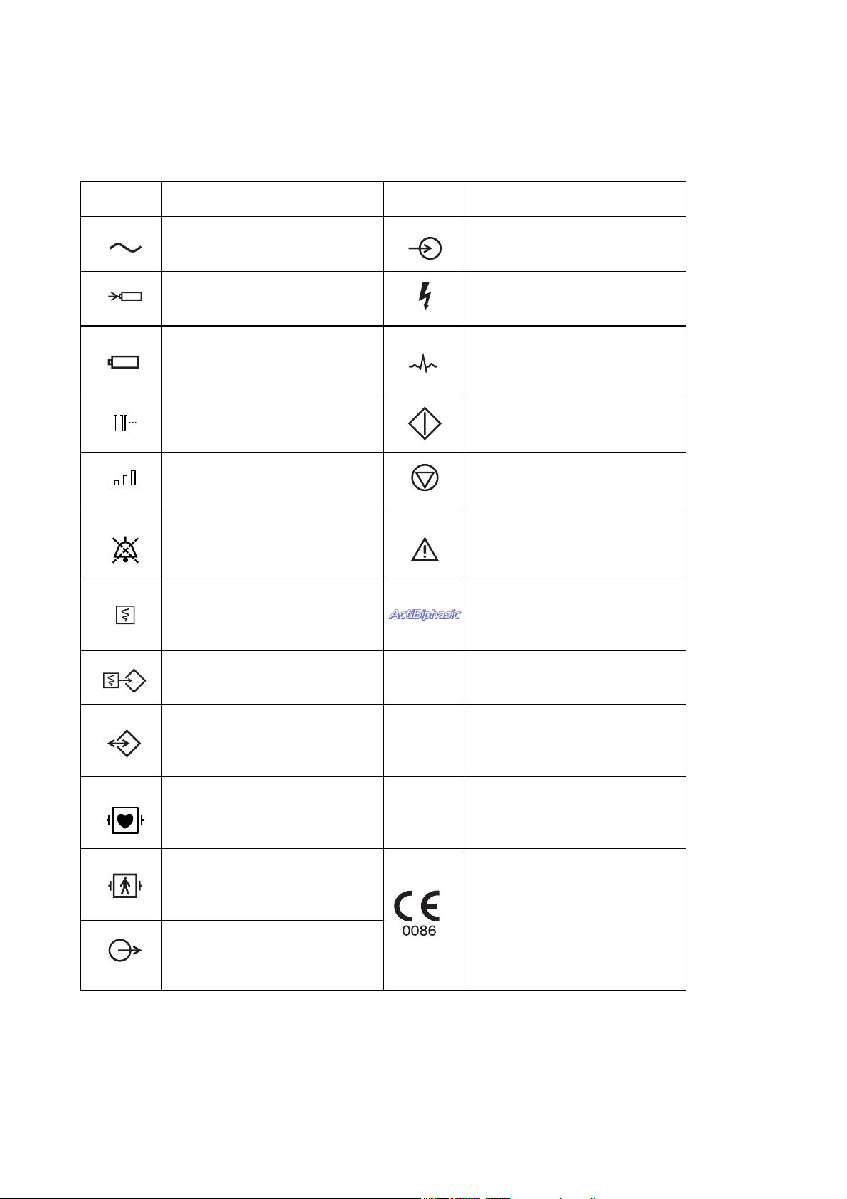
Explanations of the Symbols in this Manual and Instrument
The following symbols found in this manual/instrument bear the respective descriptions as given.
On main unit
Symbol Description Symbol Description
AC power operation Input
Charging Dangerous voltage
Charged (Battery charging is
finished)
ECG lead Pacing start
ECG sensitivity Pacing stop
Alarm off
Real time/delayed recording
Event recording Complying with IEC 60529 IPX1
Inserting or removing the memory
card
IPX1
IPX4
ECG
Attention, consult operator’s
manual
Provides ActiBiphasic waveform
defibrillation function
Complying with IEC 60529 IPX4
Defibrillation-proof type BF applied
part
Defibrillation-proof type CF applied
part
Output
vi Service Manual TEC-5500
IPX7
Complying with IEC 60529 IPX7
The CE mark is a protected
conformity mark of European
Community. The products herewith
comply with the requirements of the
Medical Device Directive
93/42/EEC.
Page 13
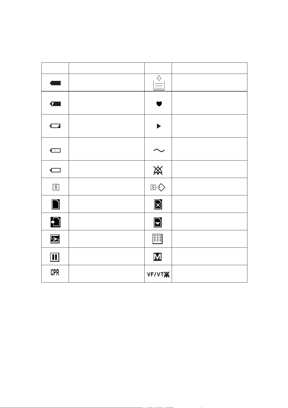
On LCD
Symbol Description Symbol Description
Battery fully charged Add Z-fold recording paper
More than 2/3 battery charge
remains
More than 1/3 battery charge
remains
3
1
0
Battery power for one 270 J
charging remains
Battery operation not available Alarm off
QRS sync mark
The point of implanted pacemaker
pulse output
AC power operation
Real time/delayed recording Event recording
SD card inserted Cannot write to the SD card
Writing to the SD card Can eject SD card
ECG cascaded display Report recording
AED analysis paused SpO2 pulse wave unstable
CPR start VF/VT alarm off
Service Manual TEC-5500 vii
Page 14

This page is intentionally left blank.
viii Service Manual TEC-5500
Page 15

Section 1 General
Introduction ......................................................................................................................... 1.1
Models and Functions ...............................................................................................1.1
General Information on Servicing ........................................................................................ 1.2
Service Policy, Service Parts and Patient Safety Checks...................................................1.4
Service Policy ...........................................................................................................1.4
Service Parts ............................................................................................................ 1.4
Patient Safety Checks .............................................................................................. 1.5
Maintenance Equipments and Tools ..........................................................................1.5
Important Safety Information ..............................................................................................1.6
Specifications ................................................................................................................... 1.21
Panel Description .............................................................................................................. 1.26
Front Panel .............................................................................................................. 1.26
Top Panel (TEC-5531 Series Only) .......................................................................... 1.27
External Paddles ..................................................................................................... 1.28
Left Side Panel ........................................................................................................ 1.28
Rear Panel .............................................................................................................. 1.29
Composition ...................................................................................................................... 1.30
Standard Components ............................................................................................. 1.30
Options.................................................................................................................... 1.32
Board/Unit Location ........................................................................................................... 1.34
Block Diagram ................................................................................................................... 1.35
Service Manual TEC-5500 1C.1
Page 16

This page is intentionally left blank.
1C.2 Service Manual TEC-5500
Page 17
Introduction
Models and Functions
1. GENERAL
This service manual provides useful information to qualified service personnel to
understand, troubleshoot, service, maintain and repair this TEC-5500 series
defibrillator
The information in the operator’s manual is primarily for the user. However, it is
important for service personnel to thoroughly read the operator’s manual and
service manual before starting to troubleshoot, service, maintain or repair this
defibrillator. This is because service personnel needs to understand the operation
of the defibrillator in order to effectively use the information in the service
manual.
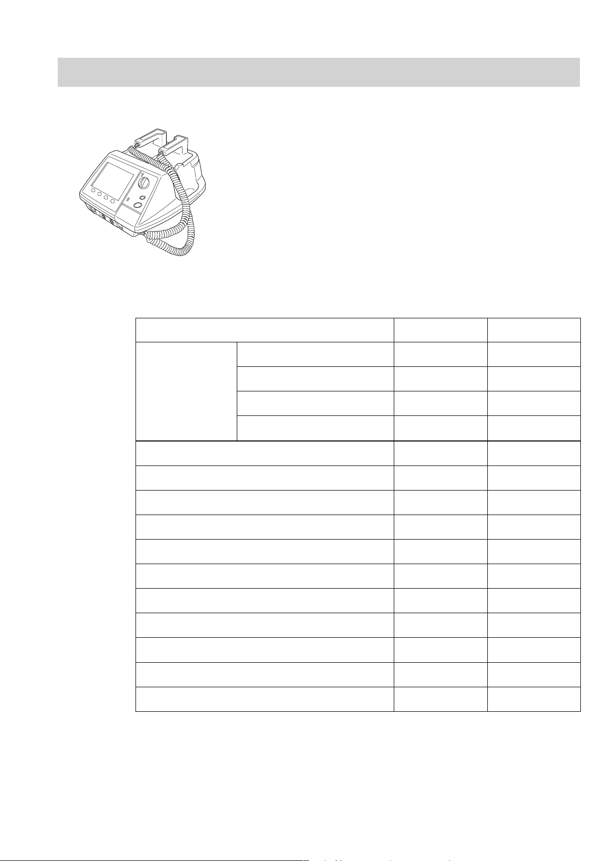
Functions TEC-5521 TEC-5531
Defibrillation and
synchronized
cardioversion
3 lead ECG Standard Standard
AED function Standard Standard
Noninvasive pacing Not available Standard
SpO2 measurement Option Option
CO2 measurement Option Option
Voice prompt Standard Standard
5 lead ECG Option Option
External ECG input Option Option
External ECG output Option Option
External paddles Standard Standard
Internal paddles Option Option
Disposable pads Option Option
Pediatric electrode assy 44 mm
φ
Option Option
SD card slot Standard Standard
Sound recording Standard Standard
Service Manual TEC-5500 1.1
Page 18

1. GENERAL
General Information on Servicing
Note the following information when servicing the defibrillator.
Safety
• There is the possibility that the outside surface of the defibrillator,
such as the operation keys, could be contaminated by contagious
germs, so disinfect and clean the defibrillator before servicing it.
When servicing the defibrillator, wear rubber gloves to protect yourself
from infection.
• There is the possibility that when the lithium battery is broken, a
solvent inside the lithium battery could flow out or a toxic substance
inside it could come out. If the solvent or toxic substance touches
your skin or gets into your eye or mouth, immediately wash it with a
lot of water and see a physician.
CAUTIONS
Liquid ingress
The defibrillator is not waterproof, so do not install the defibrillator
where water or liquid can get into or fall on the defibrillator. If liquid
accidentally gets into the defibrillator or the defibrillator accidentally
drops into liquid, disassemble the instrument, clean it with clean
water and dry it completely. After reassembling, verify that there is
nothing wrong with the patient safety checks and function/
performance checks. If there is something wrong with the
defibrillator, contact your Nihon Kohden representative for repair.
Environmental Safeguards
Depending on the local laws in your community, it may be illegal to
dispose of the lithium battery in the regular waste collection. Check
with your local officials for proper disposal procedures.
Disinfection and cleaning
To disinfect the outside surface of the defibrillator, wipe it with a non-
abrasive cloth moistened with any of the disinfectants listed below.
Do not use any other disinfectants or ultraviolet rays to disinfect the
defibrillator.
- Chlorohexidine gluconate solution: 0.5%
- Benzethonium chloride solution: 0.2%
- Glutaraldehyde solution: 2.0%
- Benzalkonium chloride: 0.2%
- Hydrochloric alkyl diaminoethylglycine: 0.5%
1.2 Service Manual TEC-5500
Page 19

1. GENERAL
Caution - continued
Transport
• Use the specified shipment container and packing material to
transport the defibrillator. If necessary, double pack the defibrillator.
Also, put the defibrillator into the shipment container after packing so
that the buffer material does not get into the inside of the defibrillator.
• When transporting a board or unit of the defibrillator, be sure to use a
conductive bag on. Never use an aluminum bag when transporting a
board or unit on which a lithium battery is mounted. Also, never use
a styrene foam or plastic bag which generates static electricity to wrap
the board or unit of the defibrillator.
Handling the defibrillator
• Because the outside surface of the defibrillator is made of resin, the
outside surface of the defibrillator is easily damaged. So when
handling the defibrillator, remove clutter from around the defibrillator
and be careful to not damage the defibrillator or get it dirty.
• Because most of the boards in the defibrillator are multilayer boards
with surface mounted electrical devices (SMD), when removing and
soldering the electrical devices, a special tool is required. To avoid
damaging other electrical components, do not remove and solder
SMD components yourself.
Measuring and Test Equipment
Maintain the accuracy of the measuring and test equipment by
checking and calibrating it according to the check and calibration
procedures.
Service Manual TEC-5500 1.3
Page 20

1. GENERAL
Service Policy, Service Parts and Patient Safety Checks
Service Policy Our technical service policy for this defibrillator is to replace the faulty unit, board
or part or damaged mechanical part with a new one. Do not perform electrical
device or component level repair of the multilayer board or unit. We do not support
component level repair outside the factory for the following reasons:
• Most of the boards are multilayer boards with surface mounted electrical
devices, so the mounting density of the board is too high.
• A special tool or high degree of repair skill is required to repair the multilayer
boards with surface mounted electrical devices.
Only disassemble the defibrillator or replace a board or unit in an environment
where the defibrillator is protected against static electricity.
As background knowledge for repair, pay special attention to the following:
• You can reduce the repair time by considering the problem before starting repair.
• You can clarify the source of most of the troubles using the information from the
troubleshooting tables. Refer to “Troubleshooting“ of this manual.
Service Parts
Refer to “Replaceable Parts List” of this manual for the service parts for technical
service that we provide.
NOTE
When ordering parts or accessories from your Nihon Kohden
representative, please quote the NK code number and part name
which is listed in this service manual, and the name or model of the
unit in which the required part is located. This will help us to
promptly attend to your needs. Always use parts and accessories
recommended or supplied by Nihon Kohden Corporation to assure
maximum performance from your defibrillator.
1.4 Service Manual TEC-5500
Page 21

1. GENERAL
Patient Safety Checks
Maintenance Equipments
and Tools
Periodic maintenance procedures and diagnostic check procedures are provided in
this manual to ensure that the defibrillator is operating in accordance with its
design and production specifications. To verify that the defibrillator is working in
a safe manner with regard to patient safety, patient safety checks should be
performed on the defibrillator before it is first installed, periodically after
installation, and after any repair is made on the defibrillator.
For patient safety checks, perform the following checks as described in the
IEC60601-1 “Medical electrical equipment - Part 1: General requirements for
safety”:
• Protective earth resistance check
• Earth leakage current check
• Enclosure leakage current check
• Patient leakage current check
• Withstanding voltage check
Test equipment
When repairing or calibrating the defibrillator, the following test equipment is
required.
• Oscilloscope: 2 channels or more for input signal, 50 mV to 5 V input range, 1/
10 attenuating probe and 100 MHz or more frequency response characteristic
must be provided.
• Power supply
• Oscillator: standard type
• Digital voltmeter: standard type (An oscilloscope can be used instead of the
digital voltmeter.)
Service Manual TEC-5500 1.5
Page 22

1. GENERAL
Important Safety Information
General
• Never use the defibrillator in a flammable atmosphere (i.e. areas with
flammable anesthetics, concentrated oxygen, hyperbaric oxygen) or in
an environment in which an electrical arc could ignite an explosion.
Otherwise, the defibrillator will explode or fire.
• Never use the defibrillator in a high-pressure oxygen medical care
tank. Otherwise, the defibrillator will explode or fire.
• The defibrillator generates high voltage. The defibrillator must only
be operated by trained and qualified medical personnel.
• Radiofrequency or Electromagnetic Field
Do not use any kind of non-essential non-patient care device within a
radius of 1 meter around the defibrillator. The use of non-essential
non-patient care devices that emit radiofrequency or electromagnetic
fields may interfere with the operation of the defibrillator by causing
noise on the ECG waveform or error messages. If a non-essential
non-patient care device is accidentally placed near the defibrillator,
quickly remove it.
• MRI examination
- Do not install this defibrillator in an MRI examination room. The
defibrillator may not operate properly due to high-frequency
magnetic noise from the MRI.
- When performing MRI tests, remove all electrodes and transducers
from the patient which are connected to this defibrillator. Failure to
follow this warning may cause serious electrical burn on the patient
due to local heating caused by dielectric electromotive force. For
details, refer to the instruction manual for the MRI.
• Using with ESU
- When using this defibrillator with an ESU, the ESU return plate and
the electrodes for monitoring must be firmly attached to the patient.
If the return plate is not attached correctly, it may burn the patient’s
skin where the electrodes are attached. Refer to the instruction
manual for the ESU.
- When using an ESU, use this defibrillator only in the MONITOR
mode and use the ECG electrodes for monitoring. Do not monitor
ECG with disposable pads, external paddles or internal paddles.
Otherwise, high frequency energy from the ESU causes abnormal
current to flow in the patient and unexpected discharge. This causes
serious electrical burn, shock, or other injury and damages the
defibrillator.
DANGER
WARNING
1.6 Service Manual TEC-5500
Page 23

1. GENERAL
WARNING continued
• Surrounding Conditions
Fluids such as Ringer’s saline solution and blood are excellent
electrical conductors; to avoid creating potentially dangerous
electrical paths, keep the defibrillator and the immediate area clean
and dry at all times.
CAUTION
• Install the defibrillator and ESU appropriately and perform
equipotential grounding. Otherwise, noise from the ESU may be
falsely recognized as QRS and ECG monitoring may not be performed
properly.
• Use only Nihon Kohden products and specified parts and accessories.
When other products, parts or accessories are used, the defibrillator
heats up and breaks down, and monitoring stops.
• Do not reuse disposable products.
Installation
WARNING
• Connect only the specified instrument to the defibrillator by following
the specified procedure. Otherwise, electrical leakage current may
harm the patient and operator.
• Connect only the specified instruments to the connector or sockets
marked with by following the specified procedure. Otherwise,
electrical leakage current may harm the patient and operator.
• Only use the provided power cord. Failure to follow this warning may
cause electrical shock to the patient and operator, and may damage
the defibrillator. When the provided power cord cannot be used,
operate the defibrillator on battery power.
• For patient safety, equipotential grounding of all instruments must be
performed. Consult with a qualified biomedical engineer.
• Do not connect several grounding leads directly to the equipotential
terminal because the grounding lead may be disconnected from the
terminal.
CAUTION
• The defibrillator should only be connected to external equipment
which complies with the CISPR 11 Second Edition 1990-09, Group 1
and Class B standard.
• Use only the KD-028A Cart for this defibrillator. If another cart is used,
the cart may tip over or the defibrillator may fall off.
Service Manual TEC-5500 1.7
Page 24

1. GENERAL
Battery
DANGER
• Keep the battery pack away from fire. Do not heat the battery pack.
Otherwise, the electrolyte comes out and the battery pack explodes.
• Never short-circuit the + and – terminals on the battery pack with a
wire. Never store or carry the battery pack with metal such as
necklace or hair pins. The battery pack short-circuits and a large
current flows, causing leakage of the substance inside the battery and
battery explosion.
• Never disassemble or modify the battery pack. Never damage or
directly solder the sheath tube. The battery pack short-circuits, the
electrolyte comes out and the battery pack explodes.
• Do not subject the battery pack to a strong mechanical shock. The
battery leaks and explodes.
• Do not use a battery which is damaged, such as from falling. There is
a gas discharge valve inside the battery and if this valve is damaged,
the gas cannot be discharged, causing the battery to explode.
• If the battery pack is damaged and the substance inside the battery
(alkaline liquid) contacts the eyes or skin, wash immediately and
thoroughly with water and see your physician. Never rub your eyes,
otherwise you may lose your eyesight.
• The battery pack has + and – polarity. Make sure that the battery is
installed with the correct polarity direction. Otherwise, the substance
inside the battery leaks and the battery pack explodes.
• Do not charge the battery pack with an instrument other than this
defibrillator. With another instrument, abnormal current flows and the
substance inside the battery leaks and the battery explodes.
• Do not connect the battery pack to an AC outlet or lighter socket in a
car. The substance inside the battery leaks and the battery pack
explodes.
WARNING
• Check the battery performance once a month.
• After battery check, immediately charge the battery.
• When you start using a new battery pack, write down the date of
battery first use on the label on the battery pack.
• Replace the battery pack every one year.
• During the battery test, the defibrillator cannot perform defibrillation
or cardioversion with battery power. Use the defibrillator on AC
operation or use another defibrillator. If the battery is deteriorated or
is not charged enough, defibrillation or cardioversion cannot be
performed.
• Do not immerse the battery pack in water or seawater. The battery
heats up and rusts and the substance inside the battery leaks.
• Never use a battery pack which is damaged, discolored or has leakage.
A damaged battery explodes if used.
• Do not leave the battery unused for more than one year. The battery
may leak.
1.8 Service Manual TEC-5500
Page 25

1. GENERAL
CAUTION
• When inserting or removing the battery, disconnect the power cord
from the defibrillator. Otherwise, the operator may get electrical
shock.
• To keep the battery fully charged, always keep the power cord
connected to the AC outlet even when the defibrillator is not used.
• Do not expose the battery pack to direct sunlight or leave in a high
temperature place. The lifetime of the battery pack may be shortened,
the performance of the battery may be degraded and the substance
inside the battery may leak.
• The battery pack must be inserted by a qualified service personnel.
• Keep the battery pack away from children.
• Before disposing of the battery, check with your local solid waste
officials for details in your area for recycling options or proper
disposal. The battery is recyclable. At the end of its useful life, under
various state and local laws, it may be illegal to dispose of this battery
into the municipal waste stream.
Service Manual TEC-5500 1.9
Page 26

1. GENERAL
Disposable Pads
WARNING
• Failure to comply with the following warnings may cause serious skin
burn or insufficient energy discharge and pacing current to the heart.
- Do not reuse disposable pads. The pads are disposable.
- If the pad package is broken, dispose of the pads and do not use
them.
- Do not use the pads if they are past the expiration date on the
package.
- Use the disposable pads as soon as possible after removing them
from the package. Do not use a pad which is left for a long period of
time after being removed from the package.
- Do not use the disposable pads if the gel has become dry, or the gel
breaks down and releases water.
- Do not use the disposable pads if the color of the gel changes to
dark brown and dark brown gel is on the protective liner.
• If any pad or connector gets wet, replace it with a new one. If a wet
pad or connector is used, it may cause electrical shock.
• Replace the disposable pads after 1 hour pacing.
CAUTION
• When using the disposable pads for long term ECG monitoring,
replace them every 24 hours. Failure to follow this caution may cause
insufficient pacing current and insufficient energy discharge to the
heart.
• Do not attach a disposable pad over another pad. Failure to follow
this caution may cause serious skin burn.
• Do not put heavy objects on the disposable pads or bend the pads.
Otherwise the pads get damaged and deteriorated, resulting in skin
burn on the patient.
1.10 Service Manual TEC-5500
Page 27

1. GENERAL
Defibrillation,
Cardioversion and AED
General
WARNING
• Before defibrillation and cardioversion, make sure that no one is in
contact with either the patient or any metal part of any equipment or
cables which supports or is connected to the patient. Failure to follow
this warning causes serious electrical shock or injury.
• Before defibrillation and cardioversion, remove all electrodes, probes
and transducers connected to a connector without a “ ” or “ ”
mark from the patient. Otherwise the operator may get electrical
shock and the connected instrument may be damaged.
• Before defibrillation and cardioversion, move all electrodes and
medicine on the patient’s chest to positions where the defibrillator
paddle or disposable pad will not touch. If the defibrillator paddle or
disposable pad directly touches electrodes or medicine, it causes skin
burn on the electrode or medicine attachment site.
• Do not carry or move the defibrillator when the charged energy
remains in the defibrillator. If the defibrillator falls, it discharges
energy and can cause electrical shock.
• For this defibrillator, the CONTACT lamp on the STERNUM paddle
indicates skin-paddle contact impedance. If the yellow or orange lamp
lights, the defibrillator may cause serious electric burn on the
patient’s skin and poor energy discharge to the patient. In case of an
emergency, medical personnel should decide whether to execute
discharge immediately, regardless of the CONTACT lamp display, or
take action to make good contact before discharge.
• Pay careful attention to the energy selection when using the pediatric
electrode plates. Applying high energy with the pediatric electrode
plates can cause serious electrical burn because the electrode plates
are small.
• Use the ECG monitoring electrodes (disposable electrodes) to monitor
the ECG waveforms. Stable ECG cannot be acquired with the PADDLE
lead because it is difficult to hold the paddles stable. ECG acquired
from external paddles, internal paddles or disposable pads is unstable
after discharge because of high polarization voltage.
• Do not perform defibrillation or cardioversion in a wet place. Before
defibrillation or cardioversion, move the patient and defibrillator to a
dry place. Otherwise the operator may get electrical shock.
• Do not discharge near a person or object other than the patient or test
electrode plate or energy checker. It may cause electrical shock to the
person or object.
• Confirm that there is no artifact on the ECG. If there is artifact on the
ECG, signals other than ECG are misrecognized to be QRS and
accidental discharge may occur which is not synchronized with the
patient’s QRS wave.
Service Manual TEC-5500 1.11
Page 28

1. GENERAL
WARNING continued
• Do not perform synchronized cardioversion with the PADDLE lead
unless it is absolutely necessary. In synchronized cardioversion with
the PADDLE lead, artifact may be misrecognized as QRS and
accidental discharge may occur which is not synchronized with the
patient’s QRS wave.
• Never select “TEST” for the ECG lead. “TEST” is for maintenance and
the waveform displayed on the screen is not the patient’s ECG. If
synchronized cardioversion is performed with the TEST lead,
accidental discharge occurs which is not synchronized with the
patient’s QRS wave and it may cause ventricular fibrillation.
• If you use the ECG signal from the monitor, before cardioversion,
check that the defibrillator discharge occurs within 60 ms of the peak
of the ECG’s R wave with a delivery checker. If this condition is not
met, the cardioversion may be ineffective or may cause ventricular
fibrillation.
• The apex-posterior placement is not suitable for ECG monitoring or
AED analysis.
• The anterior-posterior placement is not suitable for defibrillation,
cardioversion, ECG monitoring or AED analysis. Use this placement
only for pacing.
CAUTION
When performing synchronized cardioversion, confirm that the SYNC
lamp is lit before every discharge. If “Sync mode after CV” is set to
Defib on the System Setup-Configuration screen, the defibrillator
automatically turns to the asynchronous defibrillation mode.
With External Paddles
WARNING
• Apply contact gel only to the electrode plates of the external paddles.
If contact gel gets on any other part of the defibrillator, it may cause
electrical shock to the operator.
• Do not apply contact gel by hand. Failure to follow this warning may
cause serious electrical burn, shock, or other injury.
• Do not grasp the paddle handles with the wet hand or the hand with
contact gel attached. Failure to follow this warning may cause
electrical shock to the operator.
• Apply contact gel to the electrode plates of the external paddles.
Failure to apply contact gel causes serious skin burn.
• Do not touch the electrode plate or edge of the paddle. Failure to
follow this warning may cause serious electrical burn, shock, or other
injury.
1.12 Service Manual TEC-5500
Page 29

1. GENERAL
WARNING continued
• When charging or discharging, do not touch anything other than the
handles. Failure to follow this warning causes electrical shock to the
operator.
• Before discharging, confirm that the paddles are firmly pressed
against the chest wall. Failure to follow this warning causes serious
skin burn or poor energy discharge to the heart.
• Do not perform open discharge into the air. This may cause electrical
shock to the operator or damage the defibrillator.
• Do not discharge the energy if the paddles are shorted to each other
by contact gel. Failure to follow this warning causes serious electrical
burn and poor energy discharge to the heart.
CAUTION
••
• If the patient’s body is wet, thoroughly wipe the moisture off the skin
••
so that the paddles do not short to each other.
••
• Do not discharge when the paddles touch each other. This may
••
damage the defibrillator.
With Disposable Pads
WARNING
••
• Do not attach pads on the papilla, electrodes or medicine on the
••
patient’s body. Failure to follow this warning causes serious skin
burn.
••
• Fit the pad closely to the body surface so that current flows uniformly
••
through the pad. Failure to follow this warning causes serious skin
burn or insufficient energy discharge to the heart.
••
• During charging or discharging, do not touch the pads or connectors.
••
Failure to follow this warning causes electrical shock to the operator.
••
• Before discharging, confirm that the pads are firmly applied to the
••
chest wall. Failure to follow this warning causes serious skin burn or
poor energy discharge to the heart.
• Do not discharge if the pads overlap each other or if the pads are
shorted to each other by anything conductive such as contact gel.
Failure to follow this warning causes serious electrical burn and poor
energy discharge to the heart.
Service Manual TEC-5500 1.13
Page 30
1. GENERAL
guard
CAUTION
• When connecting the pad adaptor to the paddle connector, do not
bend or damage the connector pin. Otherwise energy cannot be
discharged to the pads.
• If the patient’s body is wet, thoroughly wipe the moisture off the skin
so that the pads do not short to each other.
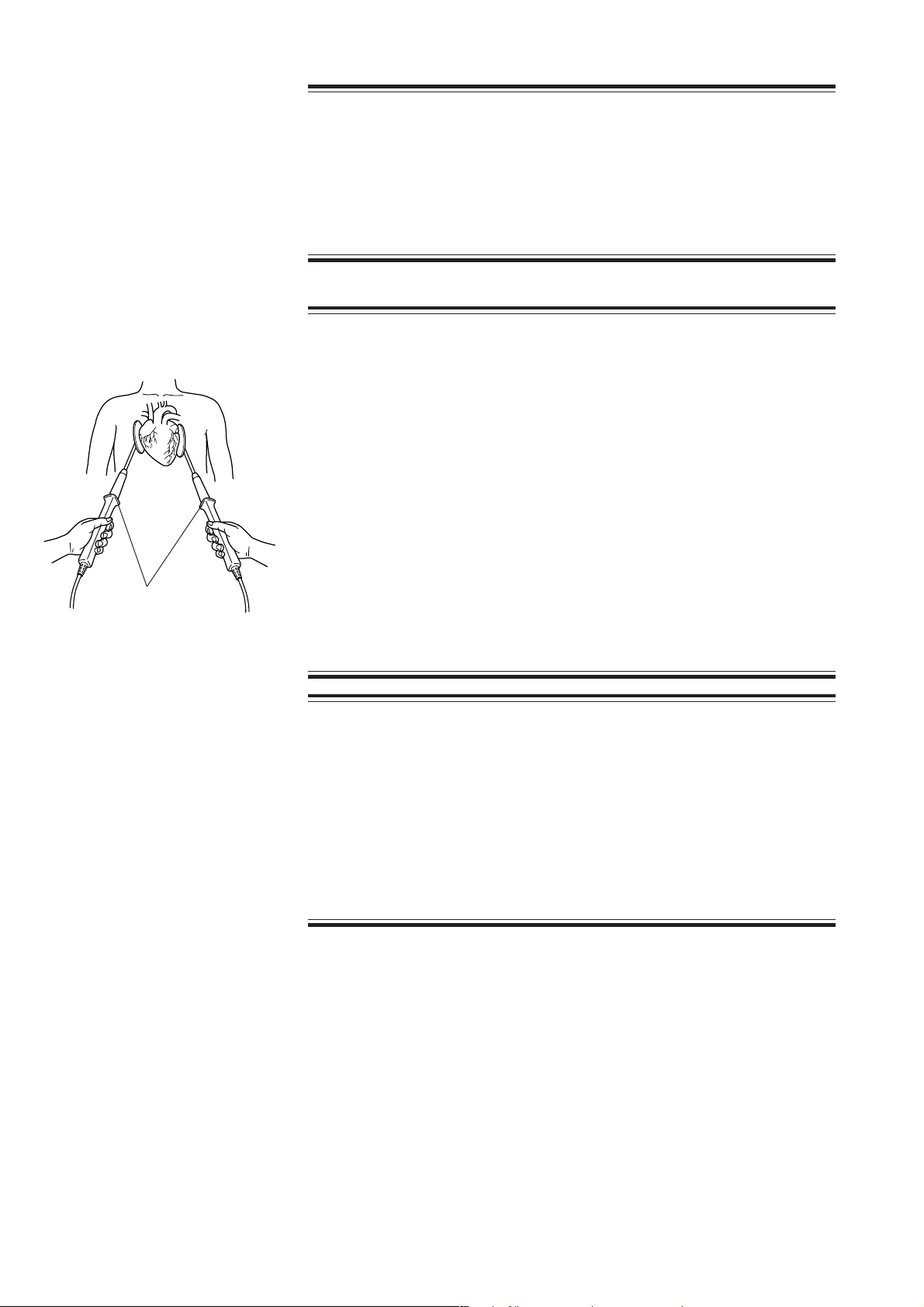
With Internal Paddles
WARNING
• Always sterilize the internal paddles before use. Failure to follow this
warning may cause serious infection.
• Pay careful attention to the energy selection when using internal
paddles. Applying high energy to the heart may cause cardiac muscle
necrosis. Low energy is recommended.
• During charging and discharging, grip the internal paddles between
the guard at the top of the handle and the cable. If you grip the handle
between the electrode and the guard, you may get an electrical shock.
• Before discharging, confirm that the paddles are firmly positioned
against the heart. Failure to follow this warning causes serious skin
burn or poor energy discharge to the heart.
• Do not perform open discharge into the air. This may cause electrical
shock to the operator or damage the defibrillator.
CAUTION
• Do not twist the internal paddle holding the electrode part or give
strong impact to the paddle. It damages the electrode part.
• When connecting the internal paddles to the paddle connector, do not
bend or damage the connector pin. Otherwise energy cannot be
discharged to the paddles.
• Do not discharge when the paddles touch each other. This may
damage the defibrillator.
1.14 Service Manual TEC-5500
Page 31

1. GENERAL
AED
WARNING
• Do not attach pads on the papilla, electrodes or medicine on the
patient’s body. Failure to follow this warning causes serious skin
burn.
• Fit the pad closely to the body surface so that current flows uniformly
through the pad. Failure to follow this warning causes serious skin
burn or insufficient energy discharge to the heart.
• When you perform defibrillation in an ambulance, stop the car.
• During charging or discharging, do not touch the pads or connectors.
Failure to follow this warning cause electrical shock to the operator.
• Before discharging, confirm that the pads are firmly applied to the
chest wall. Failure to follow this warning causes serious skin burn or
poor energy discharge to the heart.
• Do not discharge if the pads overlap each other or if the pads are
shorted to each other by anything conductive such as contact gel.
Failure to follow this warning causes serious electrical burn and poor
energy discharge to the heart.
CAUTION
• Before AED analysis or defibrillation, confirm that the patient is
unconscious and has no respiration and no pulse.
• The ECG of a child or a patient with a implanted pacemaker cannot be
analyzed correctly. For these patients, follow the physician’s
instruction.
• During AED analysis, do not touch or move the patient, pad adaptor
and disposable pad cable. Stop the life saving treatment such as CPR.
Otherwise, correct analysis result cannot be obtained. If the ECG
baseline is wandering because of surrounding conditions,
measurement conditions or electrode conditions, remove the causes
before performing AED analysis.
• When connecting the pad adaptor to the paddle connector, do not
bend or damage the connector pin. Otherwise energy cannot be
discharged to the pads.
• If the patient’s body is wet, thoroughly wipe the moisture off the skin
so that the pads do not short to each other.
• Do not discharge when the paddles touch each other. This may
damage the defibrillator.
Service Manual TEC-5500 1.15
Page 32

1. GENERAL
WARNING
• Do not perform pacing while using an ESU. Before using an ESU, turn
the defibrillator power off and remove disposable pads from the
patient. Otherwise, high frequency energy from the ESU causes
abnormal current to flow in the patient and causes serious electrical
burn, shock, or other injury. It also damages the defibrillator.
• Always monitor the ECG waveform with the ECG connection cable and
ECG electrodes.
• Confirm that there is no artifact on the ECG. If there is artifact on the
ECG, signals other than ECG are misrecognized to be QRS and
correct pacing cannot be performed.
• Do not touch the patient during pacing. Failure to follow this warning
may cause electrical shock.
• During pacing, do not touch the pads or connectors. Failure to follow
this warning causes electrical shock to the operator.
• The pacing rate must be determined by qualified medical personnel
based on the heart rate of the patient in a normal state.
• The pacing current must only be increased by qualified medical
personnel decision.
• Keep the current intensity as low as possible to minimize pain and
discomfort to the patient.
• Failure to follow the following warnings causes serious skin burn.
- Do not attach the pads over ECG electrode.
- Do not attach pads on the papilla or medicine on the patient’s body.
- Fit the pad closely to the body surface so that current flows
uniformly through the pad. This reduces the required pacing current
and pain and discomfort to the patient.
• The apex-posterior placement is not suitable for ECG monitoring or
AED analysis.
• The anterior-posterior placement is not suitable for defibrillation,
cardioversion, ECG monitoring or AED analysis. Use this placement
only for pacing.
• Never select “TEST”. “TEST” is for maintenance and the waveform
displayed on the screen is not the patient’s ECG. Failure to follow this
warning causes accidental pacing which is not synchronized with the
patient’s QRS wave.
• Do not change the sensitivity or ECG lead setting after pacing is
started. If one of these settings is changed, the pacing stops for 3
seconds. Failure to follow this warning may cause serious heart
attack.
• For 300 ms after the pacing pulse is output, no signal can be detected
as a QRS wave.
1.16 Service Manual TEC-5500
Page 33

ECG Monitoring
1. GENERAL
CAUTION
• Check that the pacing pulse is effectively working by observing ECG
on the screen.
• When connecting the pad adaptor to the paddle connector, do not
bend or damage the connector pin. Otherwise energy cannot be
discharged to the pads.
• If the patient’s body is wet, thoroughly wipe the moisture off the skin
so that the pads do not short to each other.
WARNING
• When using a defibrillator together with the monitor, use Ag/AgCl
electrodes. Other types of electrodes, stainless steel in particular, will
adversely affect the ECG waveform by slowing the baseline recovery
on the monitor and result in no monitoring immediately following
defibrillation.
• False low heart rate indicators may occur with certain pacemakers
because of electrical overshoots.
• Keep pacemaker patients under close observation. The pacemaker
rate may be counted during cardiac arrest and certain arrhythmias. Do
not rely only on heart rate alarms and the displayed heart rate.
• The apex-posterior placement is not suitable for ECG monitoring or
AED analysis.
• The anterior-posterior placement is not suitable for defibrillation,
cardioversion, ECG monitoring or AED analysis. Use this placement
only for pacing.
• With the pacing pulse rejection ON, narrow width QRS of a premature
baby or infant cannot be detected correctly and the defibrillator may
miscount QRS. In this case, set the pacing pulse rejection to OFF.
• Turn the pacing pulse rejection to OFF when monitoring a child.
Otherwise child’s QRS may not be recognized.
CAUTION
• When the “Check ECG Electrodes” message is displayed, ECG cannot
be monitored and the ECG alarm does not function. Check the
electrode, ECG connection cable, electrode leads and connection
cable and if necessary, replace it with a new one.
• Turn the pacing pulse rejection to ON when monitoring a pacemaker
patient. Otherwise QRS and pacemaker spike may not be
distinguished and pacemaker failure may not be recognized.
Service Manual TEC-5500 1.17
Page 34

1. GENERAL
SpO
Monitoring
2
WARNING
• Measurement may be incorrect in the following cases.
- increases abnormally
- When dye is injected in the blood
- When using an electrical surgery unit
- During CPR
- When there is body movement
- When there is vibration
- When measuring at a site with venous pulse
- When the pulse wave is small (insufficient peripheral circulation)
- When using an IABP (intra-aortic balloon pump)
• When not monitoring SpO2, disconnect the SpO2 adapter cable from
the defibrillator. Otherwise, noise from the probe sensor may interfere
and incorrect data is displayed on the screen.
CAUTION
• Only use the specified probes. Otherwise SpO2 cannot be monitored
properly and defibrillator performance may be degraded.
• If the “Check SpO2 unit”, “Check SpO2 probe site”, “SpO2 probe not
working”, “SpO2 module not working” or “SpO2 measurement
unstable” message appears frequently even when the probe is
attached on a site with appropriate thickness, the probe is
deteriorated. Replace the probe with a new one.
• When error messages which indicate faulty probe or SpO2 adapter
appear, stop monitoring and replace the probe or SpO2 adapter with a
new one.
CO2 Monitoring
WARNING
• When performing defibrillation or cardioversion during CO
monitoring with the CO2 sensor kit, remove the sensor from the
patient. When the sensor cannot be removed, do not touch the sensor
cable because the discharged energy may cause serious electrical
burn, shock or other injury.
• Before MRI examination, remove the CO2 sensor kit from the patient.
Failure to follow this warning may cause serious electrical burn on
the patient due to local heating caused by dielectric electromotive
force. For details, refer to the MRI operator’s manual.
1.18 Service Manual TEC-5500
2
Page 35

1. GENERAL
CAUTION
• The measurement may be inaccurate when a patient with an extremely
high respiration rate or patient with irregular respiration is monitored.
Read the measured values carefully.
• Measured value may be incorrect when the operating temperature
changes greatly.
• When the “CO2 sensor not working” or “CO2 adapter abnormality”
message is displayed, check the CO2 sensor kit and replace it if
necessary. CO2 cannot be monitored while the message is displayed.
• Only use the specified CO2 sensor kit. Otherwise CO2 cannot be
monitored properly and defibrillator performance may be degraded.
• Obey the CAUTION label on the CO2 gas cylinder.
• After the lifetime of the CO2 gas cylinder expires, the measurement
accuracy cannot be guaranteed.
Alarms
Maintenance
WARNING
All alarms except for instrument alarm group 1 are suspended during
two minutes alarm suspension.
CAUTION
• When the alarm limit is set to OFF, there will be no alarm for that limit.
Be careful when you set the alarm to OFF.
• Alarms about a parameter do not occur until the measurement of the
parameter starts.
WARNING
• When performing energy discharge test, discharge the energy with the
paddles kept in the paddle holders. Do not discharge with the paddle
released in the air or when the paddles are shorted. Failure to follow
this warning may cause serious electrical shock and damage to the
defibrillator.
• If defibrillation or cardioversion is necessary during battery test,
cancel the battery test and operate the defibrillator on AC power. Do
not use battery power because the battery may have been discharged
by the battery test.
Service Manual TEC-5500 1.19
Page 36

1. GENERAL
Storage
CAUTION
• Before maintenance (cleaning, disinfection), turn the defibrillator
power off, disconnect the power cord from the AC outlet and then
remove the battery from the defibrillator. Failure to follow this caution
may result in electrical shock and defibrillator malfunction.
• Before battery replacement, turn off the defibrillator power and
disconnect the AC power cord from the defibrillator. Otherwise, the
operator may get an electrical shock.
• Do not disassemble or repair the defibrillator. Disassembly and repair
must be performed by qualified service personnel.
CAUTION
• To prevent overheating, leave the defibrillator lying flat and do not
cover it.
• Store the disposable pads in an environment described on the pads
package. If stored in an environment other than specified, the pads
become unusable.
1.20 Service Manual TEC-5500
Page 37

Specifications
Defibrillator
Output energy (across 50 Ω) 2, 3, 5, 7, 10, 15, 20, 30, 50, 70, 100, 150, 200 and 270 J
Energy accuracy 2 J: ±0.5 J
3 J: ±1 J
5 to 15 J: ±2 J
20 to 270 J: ±10%
Output waveform Biphasic, truncated exponential constant power (across 50 Ω)
Charging time
When powered by AC 100V to 240V: to 270 J, maximum 5 s
to 200 J, maximum 3 s
When powered by 90% of the rated mains voltage:
to 270 J, maximum 5 s
When powered by a fully charged new battery at 20°C ambient temperature:
to 270 J, maximum 5 s
to 200 J, maximum 3 s
After 15 discharges at 270 J with a fully charged new battery at 20°C ambient
temperature:
to 270J, maximum 5 s
1. GENERAL
Charging display Displays the charged energy value on the screen
Synchronized discharge Available
From the peak of R wave to the peak of discharge: within 60 ms
Maximum continuous charge/discharge cycles at 270 J
20 cycles: 3 cycles per minute with 1 minute cool down period after every 1
minute charge/discharge period
15 cycles: 3 cycles per minute with no cool down period
First phase Second phaseLoad resistance
(Ω)
25 67.3 3.85 15.5 3.62
50 41.1 6.35 12.7 3.62
75 29.5 8.86 11.0 3.62
100 22.9 11.4 9.81 3.62
125 18.8 13.9 8.96 3.62
150 15.9 16.4 8.29 3.62
175 13.8 18.9 7.76 3.62
Service Manual TEC-5500 1.21
Ipk1 (A) D1 (ms) Ipk2 (A) D2 (ms)
Page 38

1. GENERAL
150
30
20
10
-10
0
02 64
8
10 12 14
16
18
20
22
24
current [A]
time [ms]
175
30
20
10
-10
0
02 64
8
10 12 14
16
18
20
22
24
current [A]
time [ms]
60
40
20
current [A]
0
-20
60
40
20
current [A]
0
-20
02 64
02 64
60
25
40
20
current [A]
0
-20
10 12 14
8
time [ms]
75
10 12 14
8
time [ms]
18
16
16
20
18
20
24
22
24
22
02 64
30
20
10
current [A]
0
-10
02 64
50
100
10 12 14
8
10 12 14
8
time [ms]
time [ms]
18
16
16
20
18
20
24
22
24
22
30
20
10
current [A]
0
-10
125
02 64
10 12 14
8
time [ms]
18
16
20
24
22
1.22 Service Manual TEC-5500
Page 39

Noninvasive Pacing (TEC-5531 series only)
Pacing rate 30 to 180 pulse/min in 10 pulse/min steps
Output current 8 to 200 mA in 5 mA steps (Set on the System Setup screen)
Pacing modes Fixed and Demand
Maximum load resistance Outputs 200 mA across 250 Ω, 120 mA across 500 Ω
External Paddle (ND552VC/VE/VK)
Paddle electrode size For adults: 70 ±3 × 10⁶ ±3 (mm2)
For children: 45 ±3 × 53 ±3 (mm2)
Paddle cord length 2.0 m or more (when it is pulled by 18 N force)
Battery
Type Ni-MH battery
Nominal voltage: 12 V
Rated capacity: 2800 mAh
TEC-5521/5531 series: With fully charged new battery at 20°C ambient temperature
- Minimum 70 discharges at 270 J
- Minimum 150 minutes continuous monitoring
- Minimum 90 minutes fixed mode pacing (180 pulse/min, 200 mA)
With the fully charged new battery at 0°C, the defibrillator can perform:
- Minimum 50 discharges at 270 J
1. GENERAL
Clock Accuracy
At surrounding temeprature 25°C (77°F): ±3 min/month
At storage temperatures -20 to 70°C (-4 to 158°F): ±5 min/month
Environment
Operating temperature: 0 to 45°C (32 to 113°F)
Operating humidity: 30 to 95% (relative humidity, non-condensing)
Operating atmospheric pressure: 70 to 106 kPa
(Recording paper may jam, if it is wet.)
Storage temperature: -20 to 70°C (-4 to 158°F)
Storage humidity: 10 to 95% (relative humidity, non-condensing)
Storage atmospheric pressure: 50 to 106 kPa
Electromagnetic Compatibility
IEC 60601-1-2: 2001
IEC 60601-2-4: 2002
Service Manual TEC-5500 1.23
Page 40

1. GENERAL
Safety
Safety standard IEC 60601-1: 1988
IEC 60601-1 Amendment 1: 1991
IEC 60601-1 Amendment 2: 1995
IEC 60601-2-4: 2002
According to the type of protection against electrical shock
Battery power: INTERNALLY POWERED EQUIPMENT
AC power: CLASS I EQUIPMENT
According to the degree of protection against electrical shock
DEFIBRILLATION-PROOF TYPE BF APPLIED PART:
External paddles, disposable pads, SpO2 adapter and CO2 sensor kit
DEFIBRILLATION-PROOF TYPE CF APPLIED PART:
Internal paddles, ECG connection cable
According to the degree of protection against harmful ingress of water: IPX1
According to the degree of safety of applicationin the presence of a FLAMMABLE ANAESTHETIC MIXTURE
WITH AIR, OR WITH OXYGEN OR NITROUS OXIDE:
EQUIPMENT not suitable for use in the presence of FLAMMABLE
ANAESTHETIC MIXTURE WITH AIR,
OR WITH OXYGEN OR NITROUS OXIDE
Mode of operation
Continuous operation with intermittent load: Operation at defibrillation mode
Continuous operation: All operation except above mentioned
Monitor
Effective display area 117.2(W) × 88.4(H) mm (5.7 inch)
Sweep length 97 mm
Sweep speed 25 mm/s, 50 mm/s
Sensitivity 10 mm/1mV ±5% (sensitivity × 1)
Amplitude limit 40 mm
ECG Amplifier
Input signal PADDLE, I, II, III, aVR, aVL, aVF, V, AUX
Frequency response Through paddles: 0.5 to 20 Hz (-3 dB)
Through ECG connection cable: 0.05 to 150 Hz (-3 dB), at AC filter off
AUX: 0.05 to 150 Hz (-3 dB)
Input impedance Through paddles: ≥100 kΩ
Through ECG connection cable: ≥5 MΩ (at 10 Hz 1mV)
AUX: ≥ 100 kΩ
CMRR ≥100 dB (against chassis ground) at AC filter On
AC filter Available (common with 50/60 Hz)
ON at ≥-20 dB, OFF
Pacing pulse rejection ON, OFF
External ECG input sensitivity 10 mm/V ± 5% (sensitivity × 1)
Heart rate counting range Defibrillation or monitoring mode: 15 to 300 bpm
Pacing mode: 15 to 220 bpm
1.24 Service Manual TEC-5500
Page 41

Recorder
Paper speed Real time/delayed ECG waveform recording: 50, 25 mm/s
Types of recording Manual recording:
real time/delayed waveform recording, report recording, event recording
Automatic recording:
record on charging after discharge, alarm recording, periodic recording
Rhythm Recognition Detector
We evaluated the rhythm recognition detector of the TEC-5500 series defibrillator using the official
electrocardiogram database provided by AHA (American Heart Association) and MIT (Massachusetts Institute of
Technology) and an electrocardiogram database of over 3000 electrocardiograms from hospitals in Japan. According
to our own evaluation, the rhythm recognition detector of the TEC-5500 series defibrillator meets the equivalent of
AAMI standards ANSI/AAMI DF-39-1993 3.3.18.
Power Requirements
AC
Line voltage: 100 to 240 V
Line frequency: 50/60 Hz (automatic switching)
Power input: Intermittent load: 450 VA or less
Continuous load: 200 VA or less
DC (Battery)
Power voltage: 12V
Power consumption Intermittent load, 18A or less
Continuous load: 4.2 A or less
Charging time: 3 hours or less
1. GENERAL
Dimensions and Weight
Dimensions 290 (W) × 172 (H) × 355 (D) mm
Weight
TEC-5521 series defibrillator 6.1 kg (External paddles use, AC unit without battery)
5.3 kg (Pad adaptor use, AC unit without battery)
TEC-5531 series defibrillator 6.3 kg (External paddles use, AC unit without battery)
5.5 kg (Pad adaptor use, AC unit without battery)
Service Manual TEC-5500 1.25
Page 42

1. GENERAL
Panel Description
Front Panel
* When DSI interface unit
is connected
1
2
1
8
* When DSI/AUXOUT interface
unit is connected
10
9
Name
LCD display
1
Energy/Mode Select control
2
Microphone
3
SYNC button/lamp
4
CHARGE/AED button
5
DISCHARGE button
6
DISCHARGE lamp
7
ECG input connector
8
2
/CO2 connector
SpO
9
AUXOUT connector
10
Paddle connector
11
3
4
5
7
6
11
1.26 Service Manual TEC-5500
Page 43

1. GENERAL
12
13
No. Name
Record key
12
Event key
13
ECG lead key
14
ECG sensitivity key
15
Silence alarms key
16
Multi-function key
17
AC lamp
18
Battery charging lamp
19
Battery charge complete lamp
20
14
15 16
17
18
19
20
Top Panel (TEC-5531 Series Only)
24
1
2
3
4
5
6
1
Name
PACING R ATE U p ke y
PACING R ATE D own key
PACING OUTPUT Up key
PACING OUTPUT Down key
START/STOP key
PULSE lamp
3
6
5
Service Manual TEC-5500 1.27
Page 44

1. GENERAL
External Paddles
44
Name
CONTACT lamp
1
CHARGE button
2
CHARGE lamp
3
DISCHARGE buttons
4
1
32
Left Side Panel
Name
Recording paper exit
1
Door release lever
2
SD card slot
3
Battery pack holder
4
2
1
4
3
1.28 Service Manual TEC-5500
Page 45

Rear Panel
1. GENERAL
12
Name
AC SOURCE socket
1
Optional unit connector
2
Service Manual TEC-5500 1.29
Page 46

1. GENERAL
Composition
Standard Components
TEC-5521C
TEC-5521E
TEC-5521K
HV-552V Biphasic HV UNIT
UR-0311 HV CPU board
UR-0313 MOTHER board
UR-0314 CPU board
UR-0315 TEST LOAD board
UR-0316 KEY board
WS-551V Recorder unit
RG-501X Paper feeder
CD-0004 Motor assy
UR-0320 REC-EXT board
CY-0026 PRE assy
CY-0029 Main unit assy
ND-552VC External paddle for C version
ND-552VE External paddle for E versino
ND-552VK External paddle for K version
ND-552X External paddle assy
ND-611V Adult plate assy
1.30 Service Manual TEC-5500
Page 47

1. GENERAL
TEC-5531C
TEC-5531E
TEC-5531K
HV-553V Biphasic HV Unit
UR-0311 HV CPU board
UR-0313 MOTHER board
UR-0314 CPU board
UR-0315 TEST LOAD board
UR-0316 KEY board
WS-551V Recorder Unit
RG-501X Paper feeder
CD-0004 Motor assy
UR-0320 REC-EXT board
UR-0304 Pacer board
CY-0026 PRE assy
CY-0029 Main unit assy
ND-552VC External paddle for C version
ND-552VE External paddle for E version
ND-552VK External paddle for K version
ND-552X Extarnal paddle assy
ND-611V Adult plate assy
Service Manual TEC-5500 1.31
Page 48

1. GENERAL
Options
JC-761V External ECG cable
JC-762V Connection cable
JC-763V Connection cable
ND-612V Pediatric electrode, 44 mm φ
ND-762V Internal paddle electrode, 25 mm φ
ND-763V Internal paddle electrode, 35 mm φ
ND-764V Internal paddle electrode, 45 mm φ
ND-765V Internal paddle electrode, 55 mm φ
ND-766V Internal paddle electrode, 65 mm φ
ND-767V Internal paddle electrode, 75 mm φ
BC-765V ECG connection cable (IEC, 5 leads)
BC-765VA ECG connection cable (AHA, 5 leads)
JC-755V Pad adapter
JC-765V Pad adapter
KD-028A Cart
DI-001A Cart tray assembly
YZ-024H9 Battery pack, NKB-301V
YZ-025H0 Paste holder kiy
1.32 Service Manual TEC-5500
Page 49

YZ-024H3 TEC Accessory set (100V/IEC)
YZ-024H4 TEC Accessory set (200V/IEC)
YZ-024H5 TEC Accessory set (100V/AHA)
YZ-024H6 TEC Accessory set (200V/AHA)
BC-763V ECG connection cable (IEC, 3 leads) for YZ-04H3/YZ-024H4
BC-763VA ECG connection cable (AHA, 3 leads) for YZ-04H5/YZ-024H6
QI-552V DSI Interface unit
UR-0317 DSI Float board
1. GENERAL
QI-553V DSI/AUXOUT Interface unit
UR-0318 AUX OUT board
Service Manual TEC-5500 1.33
Page 50

1. GENERAL
Board/Unit Location
Recorder unit
Mother board
CPU board
LCD unit
Test load board
HV capacitor
AC/DC unit
Biphasic HV unit
KEY board
Pacer board (TEC-5531 series only)
DSI interface unit (option)
1.34 Service Manual TEC-5500
Page 51

Block Diagram
1. GENERAL
Service Manual TEC-5500 1.35
Page 52

1. GENERAL
This page is intentionally left blank.
1.36 Service Manual TEC-5500
Page 53

Section 2 Troubleshooting
How to Troubleshoot ............................................................................................................2.1
Error Code ...........................................................................................................................2.2
Defibrillation .............................................................................................................. 2.3
Operation Panel .........................................................................................................2.4
Communication ......................................................................................................... 2.5
Data Error..................................................................................................................2.6
Pacing (TEC-5531 Series Only).................................................................................2.6
Message..............................................................................................................................2.7
Troubleshooting ...................................................................................................................2.9
General ...................................................................................................................... 2.9
Defibrillation ............................................................................................................ 2.10
Monitoring ............................................................................................................... 2.11
Recording ................................................................................................................2.13
Battery .................................................................................................................... 2.13
Pacing (TEC-5531 Series Only)............................................................................... 2.14
Service Manual TEC-5500 2C.1
Page 54

This page is intentionally left blank.
2C.2 Service Manual TEC-5500
Page 55

How to Troubleshoot
2. TROUBLESHOOTING
Use this section to locate, identify and solve a problem in the defibrillator or an
error message displayed on the screen. The troubleshooting tables in this section
are divided into general problems and displayed error messages.
1. Determine which troubleshooting table to use. Also refer to “Messages and
Troubleshooting” in Section 10 of the Operator’s manual.
2. In the “Error Code”, “Message” or “Problem” column, find the trouble item
that matches the problem or error message.
3. Do the action recommended in the “Action” column. (Do the first action
recommended in the “Action” column).
4. If the problem or error message is not solved, do the next action recommended
in the “Action” column. (If this does not solve the problem, do the next
recommended sections.)
5. If none of the actions solve the problem, contact your Nihon Kohden
distributor or representative.
NOTE
Before contacting your NK distributor or representative for technical
support, please complete a copy of the Maintenance Check Sheet
(the original copy is provided at the end of the Section 4
“Maintenance”), and if possible, provide additional detailed
information on the problem. Send the complete copy of the
Maintenance Check Sheet to your NK distributor or representative.
This will allow your NK distributor or representative to provide you
with the best support.
Service Manual TEC-5500 2.1
Page 56

2. TROUBLESHOOTING
Error Code
The defibrillator displays an error code if it detects an error when the power is
turned on and during operation.
NOTE
• For problems that are not reproducible, call up the System Setup
screen and print the REPORT HISTORY. Refer to the Operator's
Manual for the detail of this procedure. The error code will be lost
when the power is turned off.
• Always check all the cable connections in the defibrillator before
performing the action recommended in the troubleshooting tables in
this section. This is because a loose cable connection can cause the
defibrillator to display the error code.
An error code is displayed.
ERROR AXXX
ERROR CXXX
ERROR DXXX
ERROR KXXX
ERROR PXXX
Turn off the instrument, then turn on the instrument and do the same operation.
Is the error code
displayed?
Ye s Ye s
No
The error code is saved
in the "Report History"?
No
Error AXXX, CXXX, DXXX and
KXXX:
Perform charge/discharge test.
Error PXXX
Perform pacing test.
Is the error code
displayed?
Refer to error code
description for detail
2.2 Service Manual TEC-5500
.
Ye s
No
Instrument is normal.
But find the cause of the error code.
Page 57

2. TROUBLESHOOTING
Defibrillation
Error Code Meaning Possible Cause Action
A501
A512
A513
A524
A527
A529
A556
A566
A585
A587
A597
During standby mode, the HV capacitor
has more than 1 J energy more than one
continuous second.
When charging is started, the HV
capacitor energy did not reach 1 J
within 2 seconds.
The energy is not reached to the
selected energy within the specified
time.
After charging, the capacitor energy
falls the specified value for each
energy.
After charging, the capacitor energy is
about 15% above the selected energy.
After charging, the actual charged
energy is different from the selected
energy.
Internal discharge takes more than 20
seconds to complete.
HV capacitor's voltage did not reach its
target value 20 seconds after adjusted
internal discharge.
The voltage of the HV capacitor
exceeds its specified voltage.
When the disposable pad is used,
12.5% or more of the charged energy
remains in the HV capacitor 2 seconds
after external discharge.
When discharging, the second phase
pulse is not output.
Faulty biphasic HV unit.
Faulty biphasic HV unit.
Faulty HV capacitor.
Faulty biphasic HV unit.
Faulty HV capacitor.
Faulty biphasic HV unit.
Faulty HV capacitor.
Faulty biphasic HV unit.
Faulty biphasic HV unit.
Faulty biphasic HV unit.
Faulty CPU board.
Faulty biphasic HV unit.
Faulty biphasic HV unit.
Faulty CPU board.
Faulty biphasic HV unit.
Faulty CPU board.
Faulty biphasic HV unit.
Faulty CPU board.
Discharge HV capacitor and
replace the biphasic HV unit.
Replace the biphasic HV unit.
Replace the HV capacitor
Replace the biphasic HV unit.
Replace the HV capacitor
Replace the biphasic HV unit.
Replace the HV capacitor
Replace the biphasic HV unit.
Replace the biphasic HV unit.
Replace the biphasic HV unit.
Replace the CPU board.
Replace the biphasic HV unit.
Replace the biphasic HV unit.
Replace the CPU board.
Replace the biphasic HV unit.
Replace the CPU board.
Replace the biphasic HV unit.
Replace the CPU board.
Service Manual TEC-5500 2.3
Page 58

2. TROUBLESHOOTING
Operation Panel
NOTE
• When the power is on, the following key switch is pressed and held for more than 10
seconds, the error code of each key is displayed.
• If the key was not pressed and held, check each key function with the System
Maintenance screen. Refer to Section 4 “System Maintenance Screen - Check Hardware
Screen - Check Key Screen”.
Error Code Meaning Possible Cause Action
The ECG lead key error is detected.
The ECG sensitivity key error is
detected.
The silence alarm key error is
detected.
The multi-function key error is detected.
The record key error is detected.
The event key error is detected.
The SYNC button error (front panel) is
detected.
The CHARGE button error (front panel)
is detected.
The DISCHARGE button error (front
panel) is detected.
The CHARGE button error (apex
external paddle) is detected.
The DISCHARGE button error (apex
external paddle) is detected.
The DISCHARGE button error
(sternum external paddle) is detected.
The PACING START/STOP key error
is detected.
PACING RATE Up key error
PACING RATE Down key error
PACING CURRENT Up key error
PACING CURRENT Down key error
Faulty key board.
Faulty CPU board.
Faulty key board.
Faulty CPU board.
Faulty key board.
Faulty CPU board.
Faulty key board.
Faulty CPU board.
Faulty key board.
Faulty CPU board.
Faulty key board.
Faulty CPU board.
Faulty key board.
Faulty CPU board.
Faulty key board.
Faulty CPU board.
Faulty key board.
Faulty CPU board.
Faulty external paddles.
Faulty CPU board.
Faulty external paddles.
Faulty CPU board.
Faulty external paddles.
Faulty CPU board.
Faulty pacer board.
Faulty CPU board.
Faulty pacer board.
Faulty CPU board.
Faulty pacer board.
Faulty CPU board.
Faulty pacer board.
Faulty CPU board.
Faulty pacer board.
Faulty CPU board.
Replace the key board.K501
Replace the
Replace the key board.K502
Replace the
Replace the key board.K503
Replace the
Replace the key board.K504
Replace the
Replace the key board.K505
Replace the
Replace the key board.K506
Replace the
Replace the
Replace the
Replace the key board.K508
Replace the
Replace the key board.K509
Replace the
Replace the external paddles.K511
Replace the
Replace the external paddles.K512
Replace the
Replace the external paddles.K513
Replace the
Replace the pacer board.K516
Replace the
Replace the pacer board.K517
Replace the
Replace the pacer board.K518
Replace the
Replace the pacer board.K519
Replace the
Replace the pacer board.K520
Replace the
CPU
CPU
CPU
CPU
CPU
CPU
key
CPU
CPU
CPU
CPU
CPU
CPU
CPU
CPU
CPU
CPU
CPU
board.
board.
board.
board.
board.
board.
board.K507
board.
board.
board.
board.
board.
board.
board.
board.
board.
board.
board.
2.4 Service Manual TEC-5500
Page 59

2. TROUBLESHOOTING
Communication
Error Code Meaning Possible Cause Action
C501
C502
C507
C511
C512
C513
When the CO2 sensor kit is connected,
CO2 data is not received.
When the SpO2 adapter is connected,
SpO2 data is not received.
The battery CPU does not transfer the
battery data to the main CPU for more
than 10 seconds.
When the power is turned on, the
communication error between the RTC
(real time clock) and main CPU is
detected for one second.
The sub CPU does not update the data
in the DPRAM for one second.
The voice CPU does not update the data
in the DPRAM for one second.
The DSI CPU does not update the data
in the DPRAM for one second.
The pacing CPU does not update the
data in the DPRAM for one second.
The HV CPU does not update the data
in the DPRAM for one second.
Faulty CO2 sensor kit.
Faulty DSI Float board.
Faulty AUX OUT board.
Faulty CPU board.
Faulty SpO2 adapter.
Faulty DSI Float board.
Faulty AUX OUT board.
Faulty CPU board.
Faulty mother board.
Faulty CPU board.
Faulty CPU board.
Faulty CPU board.
Faulty CPU board.
Faulty DSI Float board.
Faulty AUX OUT board.
Faulty CPU board.
Faulty pacer board.
Faulty CPU board.
Faulty biphasic HV unit.
Faulty CPU board.
Replace the
Replace the
Replace the
Replace the CPU board.
Replace the Sp
Replace the
Replace the
Replace the CPU board.
Replace the mother board.C505
Replace the
Replace the
Replace the
Replace the
Replace the
Replace the
Replace the
Replace the pacer boardC514
Replace the
Replace the biphasic HV unit.C515
Replace the
CO2 sensor kit.
DSI Float board.
AUX OUT board.
DSI Float board.
AUX OUT board.
CPU
CPU
CPU
CPU
DSI Float board.
AUX OUT board.
CPU
CPU
CPU
O2 adapter.
board.
board.
board.
board.
board.
board.
board.
Service Manual TEC-5500 2.5
Page 60

2. TROUBLESHOOTING
Data Error
Error Code Meaning Possible Cause Action
D501
D511
D512
Data in the DRAM or flash memory is
not read out correctly (summation
error).
When the power is turned on, settings in
the System Maintenance screen do not
match the backup data in the flash
memory.
When the power is turned on, damaged
waveform report data in the flash
memory is detected.
Faulty DRAM or flash
memory.
After settings in the System
Maintenance screen are
changed, the “Flash Save”
procedure is not performed.
During power off sequence,
power down occurs.
Faulty CPU board.
During power off sequence,
power down occurs.
Faulty CPU board.
Replace the CPU board.
Perform the “Flash Save”
procedure in the System
Maintenance screen.
Delete the report data in the
System Setup screen.
Replace the CPU board.
Delete the report data in the
System Setup screen.
Replace the CPU board.
Pacing (TEC-5531 Series Only)
Error Code Meaning Possible Cause Action
P502 Pulse width of the pacing output pulse is
larger or smaller than the selected width.
P503 Current intensity of the pacing output
pulse is larger than the selected value.
P504 Current intensity of the pacing output
pulse is smaller than the selected value.
P505 Pacing output that is not requested by the
CPU is detected.
P506 Pacing output voltage exceeds the upper
limit.
P511 Error was detected in the short-mode of
the transistor.
Faulty pacer board.
Faulty CPU board. Replace the CPU board.
Faulty pacer board.
Faulty CPU board. Replace the CPU board.
Faulty pacer board.
Faulty CPU board. Replace the CPU board.
Faulty pacer board.
Faulty CPU board. Replace the CPU board.
Faulty pacer board.
Faulty CPU board. Replace the CPU board.
Faulty pacer board.
Replace the pacer board.
Replace the pacer board.
Replace the pacer board.
Replace the pacer board.
Replace the pacer board.
Replace the pacer board.
2.6 Service Manual TEC-5500
Page 61

2. TROUBLESHOOTING
Message
Message Meaning Possible Cause Action
Battery charge
timed out
Battery charging
error
Battery discharge
timed out
Capacitor test fail
CO2 module not
working
CO2 module
disconnected
ERROR AXXX
ERROR CXXX
ERROR DXXX
ERROR KXXX
ERROR PXXX
FET error
High voltage
monitor error
During battery test, the battery
was not fully charged 5 hours
after battery charging started.
During battery test
An error occurred in battery
charging
During battery test
The voltage did not decrease to
the specified level 4 hours after
battery discharging started.
Capacitor test failed. Faulty biphasic HV unit.
CO2 module is faulty.
CO2 cable is disconnected from
the defibrillator.
Faulty HV
Communication error
Faulty ROM/RAM
Faulty keys
Faulty pacing unit
The circuit to measure remaining
battery charge is faulty.
Faulty high voltage monitor circuit. Faulty biphasic HV unit or CPU
Faulty battery pack.
Faulty mother board.
Faulty battery pack.
Faulty mother board.
Faulty battery pack.
Faulty mother board.
Faulty CPU board.
Faulty HV capacitor.
Faulty CO2 sensor kit.
Faulty the DSI Float board or
AUX OUT board.
CO2 cable is disconnected from
the DSI Interface Unit or
DSI/AUX OUT Interface Unit.
Faulty DSI Float board or AUX
OUT board.
---
Faulty mother board.
board.
Replace the battery pack.
Replace the mother board.
Replace the battery pack.
Replace the mother board.
Replace the battery pack.
Replace the mother board.
Replace the CPU board.
Replace the biphasic HV unit.
Replace the HV capacitor.
Replace the
Replace the DSI Float board or
AUX OUT board.
Press the Silence alarm key to
turn off the message. If the
message still appears, the DSI
Float board or AUX OUT board
is faulty. Replace the DSI Float
board or AUX OUT board.
Turn off the defibrillator, then turn
on and do the same operation. If the
message still appears, refer to the
table for each error code.
Replace the mother board.
Turn off the defibrillator, then turn
on and do the same operation. If the
message still appears, the biphasic
HV unit or CPU board is faulty.
Replace the biphasic HV unit or
CPU board.
CO2
sensor kit.
Service Manual TEC-5500 2.7
Page 62

2. TROUBLESHOOTING
Message Meaning Possible Cause Action
Overheating The high voltage charge circuit
heats up.
Power abnormality Input power voltage is too high. Not specified battery is used. Only use the NKB-301V battery.
Replace battery Battery test result is 0 to 49%.
The
working
SpO2 module
disconnected
defibrillator
battery should be replaced with a
new one.
SpO2 module is faulty.
SpO2 cable is disconnected from
the defibrillator.
judged that the
The
defibrillator
frequently.
Faulty biphasic HV unit. Replace the biphasic HV unit.Relay drive error Faulty biphasic HV unit.
Faulty CPU board. Replace the CPU board.
Faulty battery pack. Replace the battery.
Faulty the SpO2 adapter. Replace the SpO2 adapter.SpO2 module not
Faulty the DSI Float board or
AUX OUT board.
SpO2 cable is disconnected from
the DSI interface unit or
DSI/AUX OUT interface unit.
Faulty DSI Float board or AUX
OUT board.
discharged too
Turn off the defibrillator and leave
the defibrillator for 10 minutes,
then turn on.
Replace the DSI Float board or
AUX OUT board.
Press the Silence alarm key to
turn off the message. If the
message still appears, the
Float board or AUX OUT board
is faulty. Replace the DSI Float
board or AUX OUT board.
DSI
2.8 Service Manual TEC-5500
Page 63

Troubleshooting
General
Problem Possible Cause Action
2. TROUBLESHOOTING
The defibrillator heats up. The defibrillator is used for many
hours.
No operation when the defibrillator is
turned on.
characters are not seen.
The power cord is disconnected.
The battery is not installed. Install the specified battery.
Faulty battery
Remaining battery charge is low. Charge the battery.
Faulty key board. Replace the key board.
Faulty mother board. Replace the mother board.
Faulty AC/DC unit. Replace the AC/DC unit.
Faulty LCD inverter board. Replace the LCD inverter board.Screen is dim. Waveform and
Faulty LCD unit. Replace the LCD unit.
Faulty mother board. Replace the mother board.
Faulty CPU board. Replace the CPU board.
There is no abnormality in the
defibrillator. Turn off the defibrillator
and disconnect the power cord.
Firmly connect the power cord to the
AC outlet and the defibrillator.
Replace the battery with a new one
(NKB-301V).
The printed data is JAN/01/80. The backup battery is almost
discharged.
The report data are not saved.
All settings set in the Setup screen and
System Setup screen return to the
default settings.
On the Setup screen, the report data
were deleted.
During power off sequence, power
down occurs.
Faulty CPU board. Replace the CPU board.
During power off sequence, power
down occurs.
Faulty CPU board. Replace the CPU board.
Replace the CPU board. (Under normal
use condition, the backup battery
lifetime is about 6 years.)
Deleted data cannot be recovered.
Do not disconnect the AC power cord
or do not remove the battery while the
"Shutdown" message is displayed.
Do not disconnect the AC power cord
or do not remove the battery while the
"Shutdown" message is displayed.
Service Manual TEC-5500 2.9
Page 64

2. TROUBLESHOOTING
Problem Possible Cause Action
When the battery is installed, the
defibrillator suddenly changes to
battery operation.
When the battery is not installed, the
defibrillator power suddenly drops.
The date and time printed on the
recording paper is incorrect.
Defibrillation
Power voltage changed. Check that the AC power cord is
connected to the defibrillator. If the
trouble is not solved, the AC/DC unit or
AC power cord faulty. Replace the
AC/DC unit or AC power cord.
--- Set the date and time on the Setup
screen. Refer to Section 3 of the
operator's manual
The backup battery for the clock is
discharged.
Faulty CPU board. Replace the CPU board.
Replace the backup battery.
Problem Possible Cause Action
The defibrillator self-discharges the
energy during charging.
Cannot switch to synchronized mode.
In battery operation, the battery is
almost discharged.
Faulty biphasic HV unit.
(Error code appears on the screen.)
Operate the defibrillator on AC power
and recharge the battery. The battery
is automatically charged when the
defibrillator is connected to AC power.
When an error code appears on the
screen, refer to the Defibrillation table
in the Error Code section.
Appropriate lead is not selected. Change to the appropriate lead.
You tried to perform synchronized
cardioversion with the PADDLE lead
On the Paddle Setup screen, set the
“sync by paddle lead” to ON.
but synchronized cardioversion with
the PADDLE lead is set to OFF on
the Paddle Setup screen.
Faulty key board. Replace the key board.
Faulty CPU board. Replace the CPU board.
“0 J” is printed on the defibrillation
report recording.
TTR is 15 Ω or less
TTR is 255 Ω or more.
Check that the paddles do not touch
each other.
Press the paddles on the patient
firmly.
2.10 Service Manual TEC-5500
Page 65

Monitoring
ECG
2. TROUBLESHOOTING
Problem Possible Cause Action
Dotted lines appear instead of the ECG
waveforms.
No sync sound Faulty CPU board. Replace the CPU board.
No alarm is generated
No sound Faulty speaker or speaker cable. Replace the speaker
An ECG electrode is detached.
An electrode lead is disconnected from
the electrode.
The ECG connection cable is
disconnected from the defibrillator.
An electrode lead is faulty.
Faulty mother board.
The SILENCE ALARMS key is
pressed.
On the Setup screen, alarm is set to
OFF.
Faulty CPU board. Replace the CPU board.
Faulty key board. Replace the key board.
Faulty CPU board. Replace the CPU board.
Remove the cause of the trouble. If the
trouble is not solved, the mother board
is fault. Replace the mother board.
Press the SILENCE ALARMS key
again.
On the Setup screen, set the
upper/lower limit of each vital alarm.
SpO
2
Problem Possible Cause Action
SpO2 value is not displayed on the
screen.
The SpO
disconnected from the SpO
connector.
2 adapter cable is
2/CO2
The SpO2 probe is disconnected from
the SpO
2 adapter.
Cable discontinuity in SpO2 adapter
or probe
SpO2 probe attachment to the patient
is loose.
Dotted lines appear instead of the pulse
Faulty
SpO2
probe. Replace the
waveforms.
SpO2
Faulty
adapter. Replace the
Faulty DSI Float board. Replace the DSI Float board.
Faulty AUX OUT board. Replace the AUX OUT board.
Deformed or damaged SpO2 probe Probe was disinfected in a way other
than the specified way.
SpO2 probe is repeatedly used.
Connect the SpO
SpO
2/CO2 connector.
2 adapter to the
Firmly connect the probe to the SpO
adapter.
Replace the SpO2 adapter or probe.
Firmly attach the probe to the patient.
SpO2
probe.
SpO2
adapter.
Replace the probe with a new one.
Use the specified disinfecting
method.
Replace the probe with a new one
when its lifetime is over.
2
Service Manual TEC-5500 2.11
Page 66

2. TROUBLESHOOTING
CO
2
Problem Possible Cause Action
The measured value is not displayed on
the screen.
The red LED on the CO2 adapter
blinks.
The CO2 sensor kit cable is
disconnected from the
SpO2/CO2
Connect the CO
2
/ CO2 connector.
SpO
2 sensor kit cable to the
connector.
CO2 gas is in the inspiration. With the CO2 sensor kit, measurements
are based on the assumption of no CO
gas in the inspiration. Do not connect a
Jackson Rees respiration circuit or
Mapleson D respiration circuit to the
patient. Measurement cannot be done
correctly.
The airway adapter is dirty.
Replace the airway adapter with a new
one.
The measurement is preformed where
atmospheric pressure is low, such as at
Consider the atmospheric pressure
when making evaluations.
high altitude.
CO2 sensor or CO2 adapter is faulty.
Replace the CO
2 sensor or CO2 adapter
with a new one.
The respiration has not been detected
for longer than 20 s.
The red LED blinks when the
respiration has not been detected for
longer than 20 s regardless of the alarm
setting on the defibrillator.
2
2.12 Service Manual TEC-5500
Page 67

Recording
2. TROUBLESHOOTING
Problem Possible Cause Action
Printing is blurred. Dots are missing. The specified recording paper is not
used.
The thermal head is dirty. Clean the thermal head with the head
There is no printing. The recording paper is not loaded. Load new recording paper.
Recording unit door is not properly
closed.
The recording paper is set with the
wrong side facing up.
The thermal head heats up. Stop recording and cool the
Faulty key board. Check the key function and recorder
Faulty recorder.
Faulty CPU board.
Use the specified recording paper.
cleaning pen. If the trouble not solved,
the recorder unit is faulty. Replace the
recorder unit.
Close the door until it clicks.
Set the recording paper correctly.
defibrillator down in a cooler place.
with the System Maintenance screen. If
the recorder check is passed, the key
board is faulty. Replace the key board.
Check the recorder in the System
Maintenance screen.
Printing is thick. The recording unit temperature is too
hot.
The specified paper is not used. Use the specified recording paper.Paper feeding speed is unstable.
The recorder unit is not working. Replace the recorder unit.
Faulty mother board. Replace the mother board.
Battery
Problem Possible Cause Action
The battery charging lamp is blinking.
The defibrillator and battery are too
hot.
Cool the defibrillator down in a cooler
place. If the trouble is not solved, the
recorder unit or CPU board is faulty.
Replace the recorder unit or CPU
board.
Bring the defibrillator to a cool place.
When the battery temperature
decreases, charging resumes.
Faulty battery Replace the battery with a new one.After starting battery charging, the
charging stops. (neither battery
charging lamp nor battery charge
complete lamp lights.)
Service Manual TEC-5500 2.13
Charging circuit is not working. Replace the mother board.
Page 68

2. TROUBLESHOOTING
Pacing (TEC-5531 Series Only)
Problem Possible Cause Action
Although the PULSE lamp is lit, pacing
pulse does not appear on the ECG.
Although the START/STOP lamp is lit,
pacing does not start.
Faulty pacer board. Replace the pacer board.
Faulty CPU board. Replace the CPU board.
Pacing current is set to 0 mA. Set the appropriate pacing current with
the PACING OUTPUT control.
In DEMAND mode, selected pacing
rate is slower than the patient heart rate.
Faulty pacer board. Replace the pacer board.
Faulty CPU board. Replace the CPU board.
Set the pacing rate appropriate for the
patient heart rate. When the patient
heart rate is slower than the selected
pacing rate, pacing pulse is output
automatically.
2.14 Service Manual TEC-5500
Page 69

Section 3 Disassembly
Before You Begin ................................................................................................................. 3.1
Warnings, Cautions and Notes .................................................................................. 3.1
Required Tools ........................................................................................................... 3.2
Connection Diagram ............................................................................................................3.3
Removing the Lower Casing ................................................................................................3.5
Removing the Paddles .............................................................................................. 3.5
Removing the Battery Pack ...................................................................................... 3.5
Removing the Lower Casing ...................................................................................... 3.6
Removing the CPU Board and Mother board ....................................................................... 3.7
Removing the CPU Board .........................................................................................3.7
Removing the Mother Board .....................................................................................3.8
Removing the Front Chassis ...............................................................................................3.9
Removing the Side Casing ................................................................................................ 3.10
Removing the Recorder Unit ................................................................................... 3.11
Removing the Biphasic HV Unit ........................................................................................ 3.12
Removing the HV Capacitor .............................................................................................. 3.14
Attaching the HV Capacitor ..................................................................................... 3.15
Removing the AC/DC Unit ................................................................................................. 3.16
Removing the Test Load Board .......................................................................................... 3.17
Removing the Pacer Board (TEC-5531 Series Only) ......................................................... 3.18
Removing the LCD Unit ..................................................................................................... 3.19
Removing the Key Board ...................................................................................................3.20
Removing the Energy/Mode Select Control Knob.................................................... 3.20
Removing the Speaker ...................................................................................................... 3.21
Removing the Paddle Lock Springs ................................................................................... 3.22
Removing the AC SOURCE Socket .................................................................................. 3.23
Service Manual TEC-5500 3C.1
Page 70

This page is intentionally left blank.
3C.2 Service Manual TEC-5500
Page 71

Before You Begin
Warnings, Cautions and
Notes
3. DISASSEMBLY
The procedures in this section explain how to remove, replace and install major
components in the defibrillator.
WARNING
• The HV capacitor can store lethal amounts of energy. Discharge this
capacitor before touching any high voltage component (HV capacitor,
biphasic HV unit, paddle socket or paddles).
• Removal and replacement of any components in the defibrillator
should only be done by qualified service personnel.
• To avoid the possibility of injury to yourself or damage to the
defibrillator, do not install or remove any component while the power
is on. When disassembling, make sure that the defibrillator is off, the
AC power cord is disconnected from the defibrillator and the battery
pack is removed from the defibrillator.
There are several high voltage units inside the defibrillator:
LCD backlight, high voltage capacitor, pacing DC/DC converter and
switching regulator.
CAUTIONS
• To avoid accidental discharge of static electricity which could damage
the components of the defibrillator, use a grounded wrist strap when
installing or removing any component of the defibrillator.
• Fuses on the main board and AC/DC unit cut off the power when an
abnormality occurs in the defibrillator. Eliminate the malfunction
before replacing the fuse. Use the correct fuse only.
• Use only parts recommended by Nihon Kohden to assure maximum
performance from your defibrillator.
Service Manual TEC-5500 3.1
Page 72

3. DISASSEMBLY
NOTE
When the mother board, CPU board, biphasic HV unit, HV capacitor is
replaced with a new one, do the following adjustment. Refer to
“System Maintenance Screen - Adjust AD Screen” in Section 4.
Mother board:
- ECG sensitivity and offset
- Battery voltage setting
- Paddle contact impedance threshold
CPU board:
- ECG sensitivity and offset
- Charge energy, charge time, delivered energy and TTR
- Battery voltage setting
- Paddle contact impedance threshold
Biphasic HV unit:
- Charge energy, charge time, delivered energy and TTR
- Paddle contact impedance threshold
HV capacitor:
- Charge energy, charge time, delivered energy and TTR
Required Tools
• Anti-static bench mat
• Wrist ground strap
• Phillips screwdriver (insulated type, for M3 and M4 screws)
• Hex socket driver (for 3 mm spacer bolt and nut)
• Allen wrench
• Tweezers
• Short bar
3.2 Service Manual TEC-5500
Page 73

Connection Diagram
3. DISASSEMBLY
TEC-5531 series only
Service Manual TEC-5500 3.3
Page 74

3. DISASSEMBLY
CNA605
CNA411
CNA603
CNA002
CNP401
CNA602
CNA501
CNA501
CNA604
CNA601
CNA304
CNA302
CNA303
CNA
501
CNA001
CNA004
CNP011
CNP132
CNA901
CNP131
CNA022
CNA003
CNA201
CNP301
CNA192
CNA191
CNA153
TEC-5531 with optional interface unit
3.4 Service Manual TEC-5500
Page 75

Removing the Lower Casing
3. DISASSEMBLY
Removing the Paddles
Paddle connector
Paddle release knob
1. Make sure that the power of the defibrillator is turned off.
2. Disconnect the AC power cord from the AC outlet and
defibrillator.
3. Remove the paddles. To remove the paddles, press and
hold the paddle release knob on the paddle connector and
pull the paddle connector toward you.
CAUTION
When removing the paddle, do not pull anywhere
other than the paddle connector. Otherwise, the
paddle connector or paddle cable may be damaged.
4. If the SD card is inserted, remove it. To remove the SD
card, push it in, then pull it out.
Battery pack
Battery pack holder cover
Removing the Battery Pack
SD card
1. Turn the knob on the battery holder cover
counterclockwise and remove the battery pack holder
cover.
2. Disconnect the battery cable by holding the battery cable
connector and remove the battery from the defibrillator.
Service Manual TEC-5500 3.5
Page 76

3. DISASSEMBLY
Lower casing
Interface unit
CNA605
Removing the Lower
Casing
1. Remove the seven M4×10 binding head screws (BH) and two M3×8 binding
head screws.
2. Remove the lower casing from the upper casing.
If the optional DSI interface unit or DSI/AUXOUT interface unit is installed,
1) Remove the two M3×8 binding head screws.
2) Remove the interface unit and disconnect the CNA605 cable from the
defibrillator.
3.6 Service Manual TEC-5500
Page 77

Removing the CPU Board and Mother board
3. DISASSEMBLY
Removing the CPU Board
Film connector
Film cable
1. Remove the paddles, battery pack, SD card and lower casing. Refer to
“Removing the Lower Casing”.
2 Remove the six M3×8 pan screws with washers (PS) which secure the main
shield plate 1 to the CPU board.
3. Disconnect the following cables:
• CNA302 cable: Connects to the recorder unit (thermal head)
• CNA304 cable: Connects to the LCD INV (inverter) board
• CNA303 film cable: Connects to the LCD unit
• CNA601 film cable: Connects to the KEY board
• CNA602 cable: Connects to the paddle socket
• CNA603 cable: Connects to the biphasic HV unit
• CNA604 film cable: Connects to the Pacer board (TEC-5531 series only)
To remove the film cable from the film cable connector, gently release the
lock of the film cable connector with a small flat blade driver and your finger
as shown in the expanded illustration. Be careful because the film cable
connector is easily damaged.
4. Remove the CPU board.
NOTE
When the CPU board is replaced with a
new one, do the following adjustment.
Refer to “System Maintenance Screen -
Adjust AD Screen” in Section 4.
- ECG sensitivity and offset
- Charge energy, charge time, delivered
energy and TTR
- Battery voltage setting
- Paddle contact impedance threshold
CNA604
CNA601
CPU board
Main shield plate 1
CNA303
CNA304
CNA602
CNA302
CNA603
Service Manual TEC-5500 3.7
Page 78

3. DISASSEMBLY
Removing the Mother
Board
When the CPU board is removed, you can remove the mother board.
1. Remove the main shield plate 2 and shield sheet.
2. Remove the six M3×8 spacer bolts which secure the mother board to the upper
casing.
3. Remove the two M3×8 binding head screws (BH) which secure the ECG
connector board to the front chassis
4. Disconnect the following cables:
• CNA501 cable: Connects to the battery pack, AC/DC unit and biphasic HV
unit
• CNP401 cable: Connects to the biphasic HV unit
• CNA901 cable: Connects to the recorder unit (REC-EXT board)
5. Remove the mother board from the upper casing.
Main shield plate 2
Shield sheet
CNP401
Mother board
ECG connector
board
CNJ101
CNA901
CNA501
NOTE
When the mother board is replaced with a new one, do the following
adjustment. Refer to “System Maintenance Screen - Adjust AD
Screen” in Section 4.
Mother board:
- ECG sensitivity and offset
- Battery voltage setting
- Paddle contact impedance threshold
3.8 Service Manual TEC-5500
Page 79

Removing the Front Chassis
The HV capacitor can store lethal amounts of energy. Discharge this
capacitor before touching any high voltage component (HV capacitor,
biphasic HV unit, paddle socket or paddles).
1. Remove the paddles, battery pack, SD card and lower casing. Refer to
“Removing the Lower Casing”.
2. Remove the CPU board and mother board. Refer to “Removing the CPU
Board and Mother Board”.
3. Remove the M3×8 pan screw with spring washer and washer (PSW), and
M3×6 pan screw with washer (PS) which secure the front chassis to the upper
casing.
3. DISASSEMBLY
WARNING
4. Remove the cables from the cable tie.
5. Remove the front chassis from the upper casing.
Paddle socket
Front chassis
Cable tie
Service Manual TEC-5500 3.9
Page 80

3. DISASSEMBLY
Removing the Side Casing
1. Remove the paddles, battery pack, SD card and lower casing. Refer to
2. Remove the CPU board and mother board. Refer to “Removing the CPU
3. Remove the M3×8 pan screw with spring washer and washer (PSW) which
4. Remove the M3×8 binding head screw (BH) which secures the side casing to
5. Remove the M3×6 pan screw with washer (PS) which secures the terminal of
“Removing the Lower Casing”.
Board and Mother Board”.
secures the cable tie to the spacer bolt.
the upper casing.
the CNA001 ground wire to the AC/DC unit.
6. Remove the M3×40 spacer bolt.
7. Remove the two M3×10 binding head screws which secure the battery
connector cover to the connector of the CNA501 cable.
8. Pull out the side casing. Note that the CNA303 film cable which connects the
LCD unit and CPU board runs through between the two hubs.
CNA501
Side casing
CNA001
Battery
connector cover
CNA303
3.10 Service Manual TEC-5500
Page 81

3. DISASSEMBLY
Removing the Recorder
Unit
1. Remove the M3×8 pan screw with spring washer and washer (PSW) which
secures the recorder unit to the side casing.
2. Remove the recorder unit from the side casing.
Recorder unit
Service Manual TEC-5500 3.11
Page 82

3. DISASSEMBLY
Paddle socket
CNA002
CNA411
CNA022
CNA501
CNP011
CNP401
Biphasic HV unit
CNP131(Red) CNP132
Removing the Biphasic HV Unit
The HV capacitor can store lethal amounts of energy. Discharge this
capacitor before touching any high voltage component (HV capacitor,
biphasic HV unit, paddle socket or paddles).
1. Remove the paddles, battery pack, SD card and lower casing. Refer to
“Removing the Lower Casing”.
2. Remove the CPU board and mother board. Refer to “Removing the CPU
Board and Mother Board”.
3. Remove the front chassis. Refer to “Removing the Front Chassis”.
WARNING
4. Remove the paddle socket.
1) Remove the M3×8 pan screw with spring washer and washer (PSW) which
secures the cable tie to the biphasic HV unit.
2) Remove the M3×6 pan screw with washer (PS) which secures the terminal
of the CNA002 ground wire to the AC/DC unit.
3) Disconnect the CNA411 cable from the biphasic HV unit.
3.12 Service Manual TEC-5500
Page 83

3. DISASSEMBLY
5. Disconnect the following cables:
• CNA501 cables: Connects to the battery pack, mother board and AC/DC
unit
• CNP011 cable: Connects to the Pacer board (TEC-5531 series only)
• CNA022 cable: Connects to the Pacer board (TEC-5531 series only)
6. Remove the two M3×6 pan screws with washers (PS) which secure the
terminals of CNP131 and CNP132 wires to the HV capacitor.
7. Pull out the biphasic HV unit.
NOTE
After replacing the biphasic HV unit, always check the following:
- Charge energy, charge time, delivered energy and TTR
- Paddle contact impedance threshold
Service Manual TEC-5500 3.13
Page 84
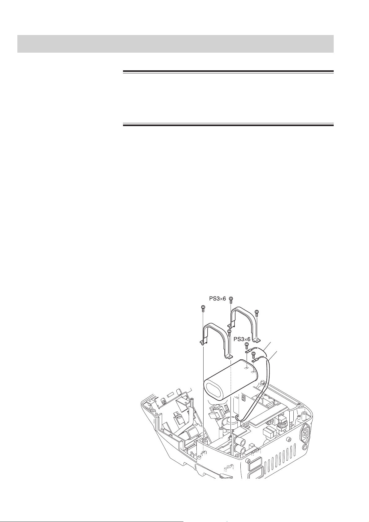
3. DISASSEMBLY
Removing the HV Capacitor
The HV capacitor can store lethal amounts of energy. Discharge this
capacitor before touching any high voltage component (HV capacitor,
biphasic HV unit, paddle socket or paddles).
1. Remove the paddles, battery pack, SD card and lower casing. Refer to
2. Remove the CPU board and mother board. Refer to “Removing the CPU
3. Remove the side casing. Refer to “Removing the Side Casing”.
WARNING
“Removing the Lower Casing”.
Board and Mother Board”.
4. Remove the four M3×6 pan screws with washers (PS) which secure the
capacitor holders to the upper casing.
5. Remove the two M3×6 pan screws with washers which secure the terminals of
CNP131 and CNP132 wires to the HV capacitor.
6. Pull out the HV capacitor.
Capacitor holder
CNP131 (Red)
CNP132
HV capacitor
3.14 Service Manual TEC-5500
Page 85

3. DISASSEMBLY
Attaching the HV Capacitor When attaching the HV capacitor, place the HV capacitor label side up and
connect the red cable from the biphasic HV unit to the red labeled connector on
the HV capacitor.
NOTE
After replacing the HV capacitor, always check the following:
- Charge energy, charge time, delivered energy and TTR
Service Manual TEC-5500 3.15
Page 86

3. DISASSEMBLY
Removing the AC/DC Unit
1. Remove the paddles, battery pack, SD card and lower casing. Refer to
“Removing the Lower Casing”.
2 Remove the two M3×6 screws with washers (PS) and two M3×8 spacer bolts
and remove the four ground wires (CNA001, CNA002, CNA003 and
CNA004).
3. Disconnect the following cables:
• CNA201 cable: Connects to the AC SOURCE socket
• CNA501 cables: Connects to the battery pack, mother board and biphasic
HV unit
4. Pull out the AC/DC unit.
AC/DC unit
CNA201
CNA501
3.16 Service Manual TEC-5500
Page 87

Removing the Test Load Board
Test load board
Test load cap
1. Remove the paddles, battery pack, SD card and lower casing. Refer to
“Removing the Lower Casing”.
2. Remove the CPU board and mother board. Refer to “Removing the CPU
Board and Mother Board”.
3. Remove the side casing. Refer to “Removing the Side Casing”.
4. Remove the HV capacitor. Refer to “Removing the HV Capacitor”.
5. Remove the test load cap.
6. Remove the two M3×6 screws with washers (PS) which secure the terminals of
the test load board wires to the upper casing.
3. DISASSEMBLY
7. Remove the two M3×6 screws with washers which secure the test load board to
the upper casing.
8. Remove the test load board.
Service Manual TEC-5500 3.17
Page 88

3. DISASSEMBLY
Removing the Pacer Board (TEC-5531 Series Only)
1. Remove the paddles, battery pack, SD card and lower casing. Refer to
“Removing the Lower Casing”.
2. Remove the CPU board and mother board. Refer to “Removing the CPU
Board and Mother Board”.
3. Remove the front chassis. Refer to “Removing the Front Chassis”.
4. Remove the side casing. Refer to “Removing the Side Casing”.
5. Disconnect the following cables from the Pacer board:
• CNP011 cable: Connects to the biphasic HV unit.
• CNA022 cable: Connects to the biphasic HV unit.
6. Remove the four M3×6 screws with washers (PS) which secure the Pacer board
to the upper casing.
7. Remove the two M3×6 screws with washers which secure the key & LED
board to the upper casing.
8. Remove the Pacer board and Key & LED board.
Pacer board
CNA022
CNP011
Key & LED board
3.18 Service Manual TEC-5500
Page 89

Removing the LCD Unit
1. Remove the paddles, battery pack, SD card and lower casing. Refer to
2. Remove the CPU board and mother board. Refer to “Removing the CPU
3. Remove the front chassis. Refer to “Removing the Front Chassis”.
4. Remove the side casing. Refer to “Removing the Side Casing”.
5. Remove the two M3×6 screws with washers (PS) which secure the LCD unit to
6. Remove the LCD unit.
3. DISASSEMBLY
“Removing the Lower Casing”.
Board and Mother Board”.
the upper casing.
LCD display
7. Disconnect the CNP301 cable from the LCD INV board and remove the
CNP301 cable from the cable tie.
8. Remove the four M3 tapping screws which secure the LCD display to the LCD
chassis.
9. Remove the LCD display from the LCD chassis.
Cable tie
LCD chassis
Tapping
screw
CNP301
Service Manual TEC-5500 3.19
Page 90

3. DISASSEMBLY
Removing the Key Board
1. Remove the paddles, battery pack, SD card and lower casing. Refer to
“Removing the Lower Casing”.
2. Remove the CPU board and mother board. Refer to “Removing the CPU
Board and Mother Board”.
3. Remove the front chassis. Refer to “Removing the Front Chassis”.
4. Remove the side casing. Refer to “Removing the Side Casing”.
5. Remove the Pacer board if it is installed. Refer to “Removing the Pacer
Board”.
6. Remove the LCD unit. Refer to “Removing the LCD Unit”.
7. Remove the followings which secure the Key board to the upper casing.
TEC-5521 Series: Six M3×6 screws with washers (PS)
TEC-5531 Series: Four M3×6 screws with washers and two M3×18 spacer
bolts
8. Disconnect the CNA153 cable from the speaker.
9. Remove the Key board.
Key board
CNA153
Knob
(Energy/Mode Select control)
Rotary switch
(Energy/Mode Select control)
Example: TEC-5531 Series
Removing the Energy/
Mode Select Control Knob
3.20 Service Manual TEC-5500
To remove the Energy/Mode Select control knob on the front panel.
1. Remove the two allen screws on the Energy/Mode Select control knob.
2. Remove the knob, nut, washer and SS3×3 O-ring from the rotary switch.
Page 91

Removing the Speaker
1. Remove the paddles, battery pack, SD card and lower casing. Refer to
2. Remove the CPU board and mother board. Refer to “Removing the CPU
3. Remove the front chassis. Refer to “Removing the Front Chassis”.
4. Remove the side casing. Refer to “Removing the Side Casing”.
5. Remove the two M3×6 pan screws with washers (PS) which secure the speaker
6. Disconnect the CNA153 cable from the Key board.
3. DISASSEMBLY
“Removing the Lower Casing”.
Board and Mother Board”.
holder to the upper casing.
CNA153
Speaker
Service Manual TEC-5500 3.21
Page 92

3. DISASSEMBLY
Removing the Paddle Lock Springs
1. Remove the paddles, battery pack, SD card and lower casing. Refer to
“Removing the Lower Casing”.
2. Remove the CPU board and mother board. Refer to “Removing the CPU
Board and Mother Board”.
3. Remove the side casing. Refer to “Removing the Side Casing”.
4. Remove the biphasic HV unit. Refer to “Removing the Biphasic HV Unit”.
5. Remove the HV capacitor. Refer to “Removing the HV Capacitor”.
6. Remove the AC/DC unit. Refer to “Removing the AC/DC Unit”.
7. Remove the eight M3×8 binding head screws (BH) which secure the paddle
locks to the upper casing.
8. Remove the paddle lock springs.
Paddle lock gasket
Paddle lock spring
3.22 Service Manual TEC-5500
Page 93

Removing the AC SOURCE Socket
1. Remove the paddles, battery pack, SD card and lower casing. Refer to
“Removing the Lower Casing”.
2. Remove the M3×6 screw with washer (PS) and M3×8 spacer bolt which secure
the terminals of the ground wires to the upper casing.
3. Remove the M3×8 screw with spring washer and washer (PSW) which secures
the cable tie to the upper casing.
4. Disconnect the CNA201 cable from the AC/DC unit.
5. Remove the two M3×8 binding head screw (BH) which secure the AC SOURCE
socket to the upper casing.
3. DISASSEMBLY
CNA201
AC SOURCE socket
Service Manual TEC-5500 3.23
Page 94

3. DISASSEMBLY
This page is intentionally left blank.
3.24 Service Manual TEC-5500
Page 95

Section 4 Maintenance
General ................................................................................................................................ 4.1
Daily Checks...................................................................................................4.1
Monthly Checks ..............................................................................................4.1
System Maintenance Screen .............................................................................................. 4.3
Calling Up the System Maintenance Screen .............................................................4.3
About the Menu Items ............................................................................................... 4.4
System Maintenance Screen Flowchart .......................................................... 4.5
Default Settings .............................................................................................. 4.6
Flash Save Procedure ...............................................................................................4.7
Configuration Screen ................................................................................................. 4.8
Adjust AD Screen .....................................................................................................4.9
Adjust ECG A/D Screen ................................................................................ 4.10
Adjust HV AD Screen ................................................................................... 4.12
Adjust Battery AD Screen ............................................................................. 4.15
Paddle Contact A/D Screen .......................................................................... 4.16
Check Hardware Screen .......................................................................................... 4.17
Check Key Screen ........................................................................................ 4.17
Check LED Screen ....................................................................................... 4.19
Check LCD Screen ....................................................................................... 4.19
Check Recorder Screen ................................................................................ 4.19
Check Time Constant Screen ....................................................................... 4.20
Check Buzzer Screen ................................................................................... 4.21
Check Memory Screen .................................................................................. 4.21
Check Voice Screen ...................................................................................... 4.22
Check ECG Frequency Screen ..................................................................... 4.23
A/D View Screen ..................................................................................................... 4.24
Operation Time Screen ............................................................................................ 4.24
Version Up Screen .................................................................................................. 4.25
Debug Mode Screen ................................................................................................4.25
Check String Screen ..................................................................................... 4.26
Memory Dump Screen ..................................................................................4.26
Periodic Replacement Schedule ........................................................................................ 4.27
Maintenance Check Sheet ................................................................................................ 4.28
Service Manual TEC-5500 4C.1
Page 96

This page is intentionally left blank.
4C.2 Service Manual TEC-5500
Page 97

General
4. MAINTENANCE
Check the following items to keep the defibrillator in optimal condition. You can
check each function and adjust the settings of the defibrillator in the System
Maintenance screen. The maintenance check sheet is provided at the end of this
section. Use this sheet to check the defibrillator after any component is replaced.
Daily Checks
Check the following items every day. Refer to “Basic Checks” in Section 2 of the
Operator’s manual).
• Discharge check
• Battery check
• Recorder check
• Alarm check
• Voice check
Monthly Checks
Check the following items once a month. Refer to “Periodic Check” in Section 10
of the Operator’s manual)
• External paddles
• Energy discharge Test
• Checking energy charge at 270 J and disarm (Charge and internal discharge)
• Battery test (Check the battery appearance every 6 months.)
• HV capacitor test
• Recorder test
• Date and time adjustment
Service Manual TEC-5500 4.1
Page 98

4. MAINTENANCE
NOTE
• Make sure that the date and time printed on the recording paper is
correct. The date and time on the recording paper are important
parts of the medical record.
• When the mother board, CPU board or biphasic HV unit is replaced
with a new one, do the following adjustment. Refer to “System
Maintenance Screen - Adjust AD Screen”.
Mother board:
- ECG sensitivity and offset
- Battery voltage setting
- Paddle contact impedance threshold
CPU board:
- ECG sensitivity and offset
- Charge energy, charge time, delivered energy and TTR
- Battery voltage setting
- Paddle contact impedance threshold
Biphasic HV unit:
- Charge energy, charge time, delivered energy and TTR
- Paddle contact impedance threshold
HV capacitor:
- Charge energy, charge time, delivered energy and TTR
4.2 Service Manual TEC-5500
Page 99

System Maintenance Screen
• The defibrillator cannot perform ECG monitoring and defibrillation
when the System Maintenance screen is displayed. You have to turn
the power off and then on to perform ECG monitoring and
defibrillation.
• Before changing or adjusting a setting in the System Maintenance
screen, write down or print out all settings. The settings for
defibrillation, ECG waveform acquisition and battery are adjusted in
the factory for each defibrillator. If different settings are used, the
defibrillator may malfunction.
• You must perform the “Flash Save” procedure in the System
Maintenance - Configuration screen after any setting in the
Configuration screen and Adjust AD screen is changed or adjusted.
The new setting or adjustment is not applied and saved until the
“Flash Save” procedure is performed. Otherwise, the “D511” error
code appears next time the power is turned on.
4. MAINTENANCE
CAUTIONS
Calling Up the System
Maintenance Screen
When an error is detected when the defibrillator is in the System Maintenance
screen mode, the error code is displayed on the upper right corner of this screen.
1. Connect the AC power cord
2. While pressing and holding the Silence alarms key, turn the Energy/Mode
Select control to the “SETUP” position. The System Setup - Menu screen
appears.
3. Release the Silence alarms key.
4. While pressing the Multi-function key, press the following keys on the front
panel one by one:
ECG lead key → Silence alarms key → ECG sensitivity key.
The System Maintenance - Menu screen appears.
5. Release the Multi-function key.
Service Manual TEC-5500 4.3
Page 100

4. MAINTENANCE
The function keys at the bottom of the screen change according to the selected
screen.
• To call up the sub-screen for each item.
1) Press the Item key to select the item. The cursor moves to the next item.
2) When the item is selected, press the OK key. The menu screen of the
selected item appears.
About the Menu Items
• To exit the System Maintenance Screen, turn the power off by turning the
Energy/Mode Select control to the “OFF” position.
• To print the information displayed on the System Maintenance screen, press the
record key on the front panel.
There are eight items in the System Maintenance - Menu screen.
Screen Settings
1 Configuration Changes the settings in the following items:
Language, Highcut Filter, Alarm Off Message,
Battery Insert Message, DSI Option, Pacing
Option, Freeze Function, Use Other Power,
Charge Time Clear, Default Setting, Flash Save
2 Adjust AD Changes the A/D values for ECG waveform
acquisition, biphasic HV unit, battery voltage and
paddle contact impedance threshold.
3 Check Hardware Checks the operation of the key switches, LEDs,
recorder, memories, sounds, etc
4 AD View Checks the A/D values that the main CPU
currently receives.
5 Operation Time Displays the count of external discharges and
operation time.
6 Version Up You can update the system program and data
7 Debug mode Displays the characters used in this defibrillator
and checks the flash memory.
8 Alarm Setting Select “Off” to turn off the ECG, SpO2 and CO
alarms.
2
4.4 Service Manual TEC-5500
 Loading...