

Page 1

Life
Scope
EC
BEDSIDE
BSM-1101/1102
MONITOR
0634-001334B
Page 2
Page 3
Page 4
Page 5
Page 6

0Ο,
Problems
Diagnostic
BoardÜnitDescriptions..........................................
Disassembly
Maintenance
Replaceable
QI-101P
Network
General
Parts
Troubleshooting
Manual
Functional
Removing
Maintenance
Check
Power
on
Мапиа|
Functional
Digital
Analog
General
Ветоута
Disassembling
AssemblingAA-101P................................
Measuring
External
safetyCheck......................................
Check
СПеск
Circuit
Circuit
and
of
Parts
Card
i
Description
Check
Block
the
Network
...........................................
Measuring
External
safetyCheck......................................
Check
of
.Ne
Self
Check
.............
Block
Diagram
1…… せ …
せ せ
eo
ASSEMDIY
Information
АА-101Р
and
Check
Measuring
................
Нот
AA-101P
Test
Equipment
i
List
ii
eee
.4
Diagram
and
Check
Communication
.............
Card
Test
Equipment
i
2000000000000
"ie
.........
В$М-1101/1102
eo
2000000000000
Parameters
e
from
the
e
нии
"VV.
Bedside
нии
000
nn
............
on
PK PK
Monitor
nK O KKK
PKR KRK
o
KKK
KKK PKR ARR
KK
PRK
PK
KKK KKK
ーーーーーー………・
PK
KR
PPK
KR P KKK
eee
eee
eee
nn n n n nn
K K K
KK KKK KKK
AKE
KKK
PREPARE
eee
нинининненнне:
KRK
KKK PKR
aneen
eee
ee
CONTENTS
KAKAO K nné
es
eee
ELEG
KKK
Kn
rn
aneen
P
KKK KRK
PARK
KRK
KK
LEE
EEEE
rn
aneen
nn
ner
εν
ner
A.3
A.4
A.4
А.4
A.8
A.8
A.9
A.9
A.10
A.10
A.10
A.11
A.12
A.12
A.12
A.12
A.12
A.13
A.14
A.15
A.15
A.15
A.15
A.16
A.22
A.23
A.23
A.23
A.23
A.24
A.24
Service
Manual
BSM-1101/1102
C.5
Page 7
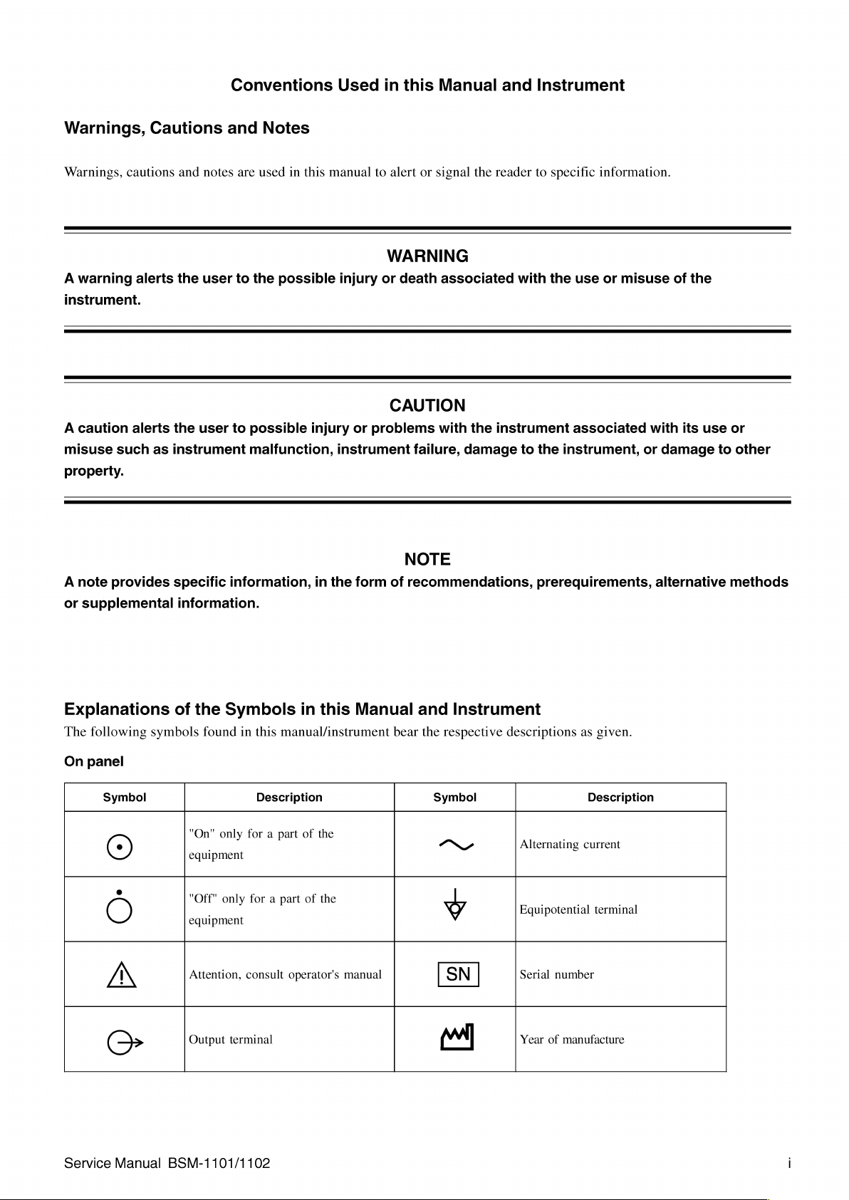
Conventions
Used
in
this
Manual
and
Instrument
Warnings,
Warnings,
A
warning
instrument.
A
caution
misuse
property.
cautions
alerts
alerts
such
Cautions
and
notes
the
user
the
user
as
instrument
and
Notes
are
used
to
the
to
possible
malfunction,
in
this
possible
injury
manual
to
injury
or
problems
instrument
alert
or
WARNING
or
death
CAUTION
failure,
signal
the
associated
with
the
damage
reader
to
specific
with
the
instrument
to
the
information.
use
or
misuse
associated
instrument,
with
or
of
the
its
damage
use
to
or
other
A
note
provides
or
supplemental
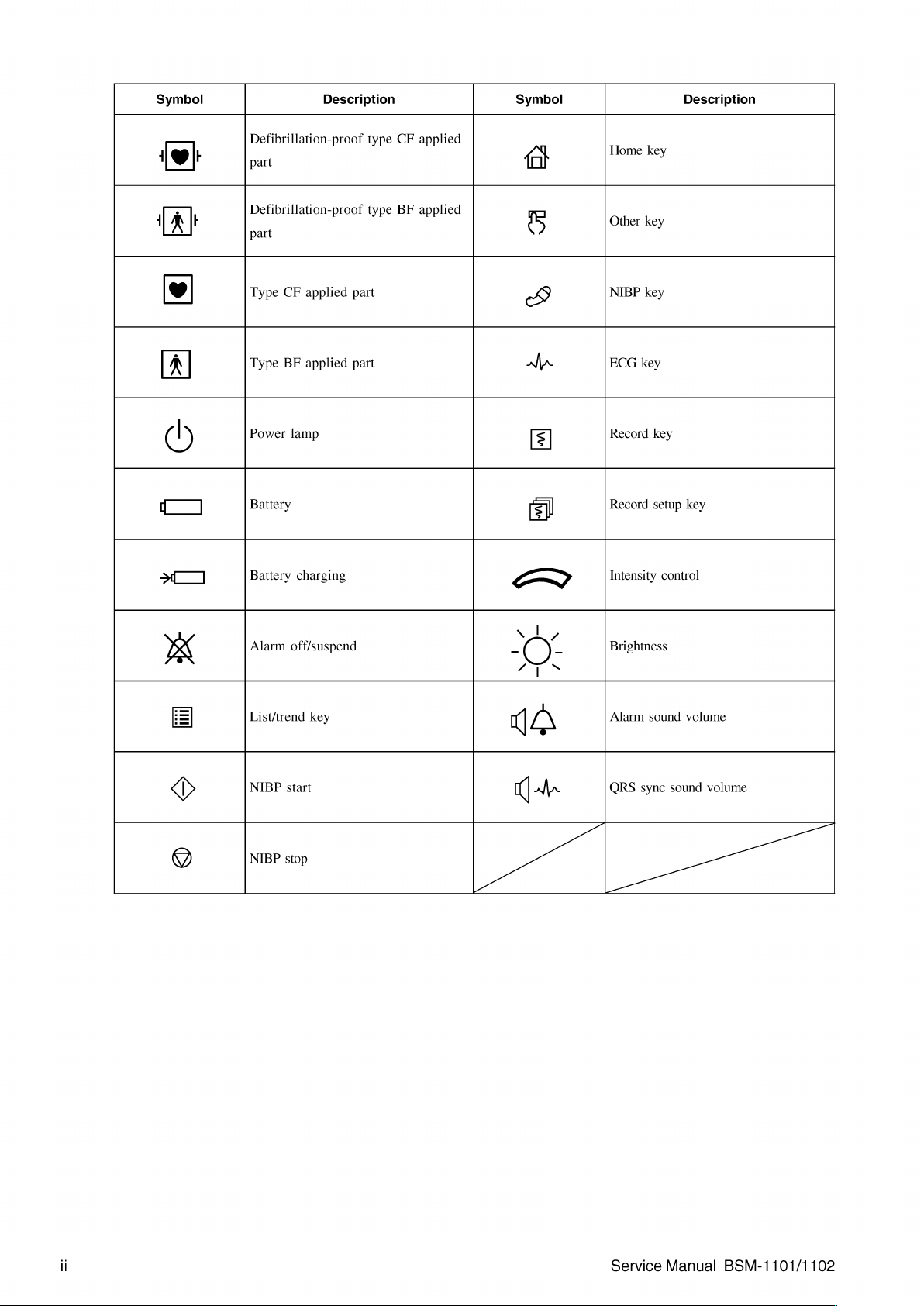
Explanations
The
following
On
panel
Symbol
(9)
symbols
specific
information.
of
information,
the
Symbols
found
"On"
only
|
equipment
"Off"
only
|
equipment
in
in
in
this
manual/instrument
Description
for a part
for a part
of
of
the
this
the
the
form
of
Manual
bear
NOTE
recommendations,
and
Instrument
the
respective
Symbol
ONY
prerequirements,
descriptions
Alternating
Equipotential
|
| | |
as
given.
Description
current
terminal
alternative
methods
/N
Service
Manual
Attention,
Output
terminal
BSM-1101/1102
consult
operator's
manual
Serial
number
Year
of
manufacture
Page 8
Symbol
Description
Symbol
Description
1 y |
| À E
®
A
(Г
Ч
|
>]
Defibrillation-proof
part
Defibrillation-proof
part
Type
CF
Type
BF
Power
lamp
Battery
Battery
applied
applied
charging
part
part
type
type
CF
BF
applied
applied
<
(at
5
©
a
>
Home
key
Other
key
NIBP
key
ECG
key
Record
key
Record
setup
Intensity
control
key
Alarm
off/suspend
B
|
im
©
|
9
List/trend
NIBP
start
NIBP
stop
key
"O:
Brightness
Alarm
sound
QRS
sync
volume
sound
volume
Service
Manual
BSM-1101/1102
Page 9

On
screen
Symbol
Dx
€
Alarm
Alarm
minutes
Alarm
QRS
Description
recording
suspend
recording
syne
mark
off
with
remaining
Symbol
[|<
4
G
Out
of
paper
Paper
magazine
Manual
Periodic
Description
open
recording
recording
PR
Ki
CA
Other
Symbol
ES
CE
0086
Pulse
sync
Network
mark
communicatin
5
(O
Description
Recycle
The
CE
mark
is a protected
conformity
Community.
comply
Medical
93/42/EEC.
mark
with
Device
of
the
The
products
the
requirements
Directive
European
herewith
of
the
Calibration
Service
Manual
BSM-1101/1102
Page 10
Section
1
General
Introductiom
Service
Specifications
Composition
Panels
Storage
Hard
Keys
Upgrading
.4
Policy
and
Patient
Service
PatientSafetyChecks
and
Front
Right
leftSidePanel......................................
Rear
Storage...................
TTANSPOTNt
How
Policy
.4
DISPÍQY
TrendgrapP
Аагт
...........
ECGMeasuremeni..............................
SpO,
Measurement
Non-invasiveBloodPressureMeasurement.............».»..»...............
VitalSignsList...................................
External
Recorder
Battery … せ
Transmitter
Transmitter
PowerReguiremenis
ENVIFONMENT............
DimensionsandWelight.....................................
Safety
Controls
Pane|
Side
Panel
and
TranSpott
and
System
to
능 아 6611
StandardS
ини
.4
Panhel................
eee
i
..........
Soft
Keys
Software/Changing
Upgrade
./
이이
Safety
.4
cooooccooccococnononcnncncnncconcncnncnonnnn
eee
Output
WS-120P
ee
ZB-800PG/PK
ZB-800PA
.4
.......................
i
Checks
............................................
(Option)
.................
...............
(optional)
(optional)
.........................................
e
i
Language
the
Instrument
이니 이 이 이 미
이 다 파 파 파 피 파 파 마 파 파 파 파 마 파 마 파 다 마 파 마 파 파 파 파 마 파 마 파 파 파 파 마 마 다 파 파 마 파 마 파 다 다 디 이니
System
nan
nn
narra
nr
rn
ини
pp
0000000000000
on
Software
nn n KK
Screen
and
eee
rn
rn
nr
rnrrr
rn
nrrnnnrrnrrrnnrrnnrrrnnrrnnannnnes
K
KK
KK
KKK O KKK
KKK
e
e
eee
nn
P
KKK P KKK P KKK
eee
KRKA
KK
KK P KK KR P KKK
„ee
Change a Language
ne
nen
KKK
KKK
ss
eee
kk
n K n
seen K Kan
KK
KR
KAKAO
on
1.1
nen
1.2
1.2
enao
1.2
1.3
1.3
KKK
tn
1.3
1.3
1.3
Rent
ne
1.3
1.4
1.5
1.5
nn n 1.5
1.5
1.5
ーー
1.5
1.6
ーー
1.6
n
1.6
1.6
KK
1.7
1.8
1.8
KARR
RKK
1.10
1.11
1.12
1.13
1.13
1.13
KKK K nn n 1.14
1.15
1.15
Service
Manual
BSM-1101/1102
1C.1
Page 11

This
service
provides
and
the
repair
the
“instrument”
All
replaceable
clearly
listed
and
repair.
manual
is
intended
information
BSM-1101
in
this
service
parts
or
subassemblies
and
illustrated
for
required
or
BSM-1102
manual).
with
use
by
to
understand,
Bedside
of
exploded
qualified
troubleshoot,
Monitor
this
instrument
parts
views
service
(referred
and
to
aid
1.
personnel
service,
to
its
optional
you
in
parts
GENERAL
only.
It
maintain,
as
the
units
location
are
Section
6,
qualified
describes
Although
service
manual
personnel
before
“Maintenance,”
service
personnel
the
maintenance
the
operator’s
attempting
to
thoroughly
describes
only.
that
can
manual
to
troubleshoot,
the
The
maintenance
be
is
written
read
both
maintenance
performed
primarily
the
service
service,
that
section
by
the user.
for
manual
or
maintain
should
in
the
the
user,
and
the
be
performed
operator’s
it
is
important
the
operator’s
instrument.
by
manual
for
Service
Manual
BSM-1101/1102
1.1
Page 12
1.
GENERAL
Service
Policy
Nihon
Kohden
faulty
printed
most
of
the
boards
We
do
not
recommend
multilayered
When
device
and
ordering
Corporation
and
manual.
Corporation
This
accessories
Corporation’s
circuit
board
are
multilayer
the
boards
outside
parts
or
distributor,
the
NK
part
helps
us
recommended
to
ensure
basic
policy
(board),
boards
repair
or
the
factory.
accessories
please
number
attend
the
to
maximum
for
technical
part,
or
unit
with
surface-mounted
replacement
NOTE
from
provide
and
your
or
the
part
needs
supplied
performance
service
with a new
of
electrical
your
nearest
name
name
listed
promptly.
by
Nihon
or
of
one.
model
devices
in
your
is
to
replace
This
is
electrical
on
Nihon
of
this
service
Always
Kohden
instrument.
any
because
devices.
these
Kohden
the
use
parts
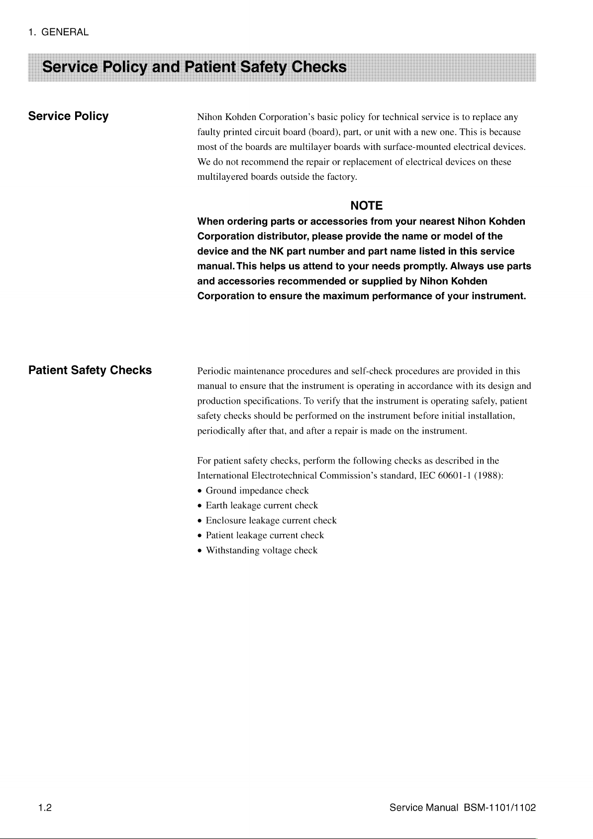
Patient
Safety
Checks
Periodic
manual
production
safety
periodically
For
International
e
e
e
e
e
maintenance
to
ensure
specifications.
checks
after
patient
Ground
Earth
Enclosure
Patient
Withstanding
safety
Electrotechnical
impedance
leakage
leakage
leakage
that the
should
that,
checks,
current
current
voltage
procedures
instrument
To
verify
be
performed
and
after a repair
perform
check
check
current
check
check
check
and
self-check
is
operating
that
the
on
the
instrument
is
made
the
following
Commission’s
procedures
in
accordance
instrument
before
on
the
checks
standard,
are
provided
with
is
operating
initial
instrument.
as
described
IEC
60601-1
in
this
its
design
and
safely,
patient
installation,
in
the
(1988):
1.2
Service
Manual
BSM-1101/1102
Page 13
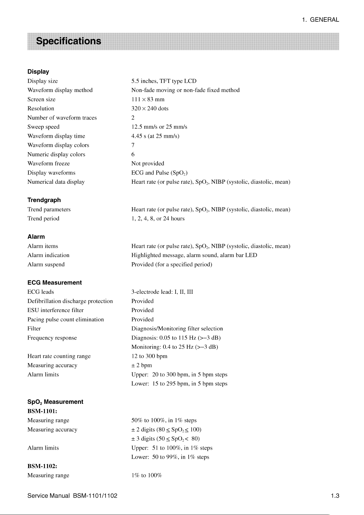
Display
Display
size
Waveform
Screen
size
Resolution
Number
Sweep
of
speed
Waveform
Waveform
Numeric
display
Waveform
Display
waveforms
Numerical
display
waveform
display
display
colors
freeze
data
display
method
traces
time
colors
5.5
inches,
Non-fade
111 x 83
320 x 240
2
12.5
mm/s
4.45 s (at
7
6
Not
provided
ECG
and
Heart
rate
TFT
moving
mm
dots
or
25
25
mm/s)
Pulse
(or
pulse
type
LCD
or
non-fade
mm/s
(SpO,)
rate),
fixed
SpO,,
NIBP
method
(systolic,
diastolic,
mean)
1.
GENERAL
Trendgraph
Trend
parameters
Trend
period
Alarm
Alarm
items
Alarm
indication
Alarm
suspend
ECG
Measurement
ECG
leads
Defibrillation
ESU
interference
Pacing
pulse
discharge
count
Filter
Frequency
Heart
Measuring
Alarm
rate
limits
response
counting
accuracy
protection
filter
elimination
range
Heart
rate
(or
pulse
rate),
1,
2,
4,
8,
or
24
hours
Heart
rate
(or
pulse
rate),
Highlighted message,
Provided
3-electrode
(for a specified
lead:
I,
II,
Provided
Provided
Provided
Diagnosis/Monitoring
Diagnosis:
Monitoring:
12
to
300
0.05
bpm
0.4
to
to
115
25
+ 2 bpm
Upper:
Lower:
20
15
to
to
300
295
bpm,
bpm,
SpO.,
SpO.,
alarm
period)
III
filter
Hz
(>—3
Hz
(>—3
in 5 bpm
in 5 bpm
NIBP
NIBP
sound,
alarm
selection
dB)
dB)
steps
steps
(systolic,
(systolic,
bar
LED
diastolic,
diastolic,
mean)
mean)
SpO,
Measurement
BSM-1101:
Measuring
Measuring
Alarm
limits
BSM-1102:
Measuring
Service
range
accuracy
range
Manual
BSM-1101/1102
50%
to
100%,
+ 2 digits
+ 3 digits
Upper:
Lower:
1%
to
51
50
100%
in
1%
(80 < SpO;<
(50 < SpO,<
to
100%,
to
99%,
in
steps
100)
80)
in
1%
1%
steps
steps
1.3
Page 14
1.
GENERAL
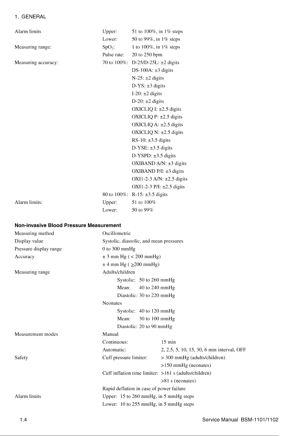
Alarm
limits
Measuring
Measuring
Alarm
limits:
range:
accuracy:
Upper:
Lower:
SDO>:
Pulse
70
to
80
to
Upper:
Lower:
rate:
100%:
100%:
51
to
100%,
50
to
99%,
1
to
100%,
20
to
250
bpm
D-25/D-25L:
DS-100A:
N-25:
D-YS:
1-20:
D-20:
OXICLIQ
OXICLIQ
OXICLIQ
OXICLIQ
RS-10:
D-YSE:
D-YSPD:
+2
+3
+2
+2
+3.5
+3
digits
digits
digits
digits
I:
P:
A:
N:
+3.5
+3.5
OXIBAND
OXIBAND
OXI1-2-3
OXI1-2-3
R-15:
51
50
to
to
A/N:
P/I:
+3.5
100%
99%
in
1%
in
1%
in
1%
+2
digits
digits
+2.5
+2.5
+2.5
+2.5
digits
digits
digits
A/N:
P/I:
+3
+2.5
£2.5
digits
steps
steps
steps
digits
digits
digits
digits
+3
digits
digits
digits
digits
Non-invasive
Measuring
Display
Pressure
value
display
Accuracy
Measuring
Measurement
Safety
Alarm
limits
Blood
method
range
range
modes
Pressure
Measurement
Oscillometric
Systolic,
0
to
+3
+ 4 mm
Adults/children
Neonates
Manual
Continuous:
Automatic:
Cuff
Cuff
Rapid
Upper:
Lower:
diastolic,
300
mmHg
mm
Hg ( <
Hg ( >200
Systolic:
Mean:
Diastolic:
Systolic:
Mean:
Diastolic:
pressure
inflation
deflation
15
to
10
to
and
200
mmHg)
mmHg)
50
to
40
to
30
to
40
to
30
to
20
to
limiter:
time
limiter:
in
case
260
mmHg,
255
mmHg,
mean
pressures
260
mmHg
240
mmHg
220
mmHg
120
mmHg
100
mmHg
90
mmHg
15
min
2,
2.5,
5,
10,
15,
>
300
>150
mmHg
mmHg
(adults/children)
(neonates)
>161 s (adults/children)
>81 s (neonates)
of
power
failure
in 5 mmHg
in 5 mmHg
steps
steps
30, 6 min
interval,
OFF
1.4
Service
Manual
BSM-1101/1102
Page 15

Vital
Signs
Parameters
Total
number
measurement
List
of
times
in
list
Heart
NIBP
120
120
rate,
(systolic,
for
periodic
for
NIBP
pulse
list
rate
diastolic,
vital
signs
mean)
list
and
SpO,
1.
GENERAL
External
ZB-800PA
ZB-800PG
ZB-800PK
Recorder
Paper
speed
Recording
Number
of
Annotation
Effective
printing
Battery
Type
of
battery:
Operation
Charging
Battery
mode:
life:
Output
interface
interface
interface
WS-120P
mode
channels
printing
width
time:
(option)
12.5
mm/s,
25
mm/s
Waveform
2
max
Date
sensitivity,
48
mm
NKB-101,
and
time,
recording,
reason
recording
NiCd,
Approx. 2 hours
the
POWER
Standard
Approx.
SAVE
and
trickle
200
charge/discharge
trend
for
speed
1.7
AH
(no
recording,
MODE
charging
recording,
recording,
no
set
to
on)
mode,
cycles
list
recording
parameter
alarm
occurrence,
with
automatic
fully
data,
ECG
no
NIBP
charged
new
selection
lead,
filter
measurement
battery
on/off,
and
Transmitter
Transmission
Transmission
Modulation
Bandwidth
Frequency
method
deviation
ZB-800PG/PK
frequency
power
(optional)
CH1001
CH2001
CH3001
CH4001
CH5001
CH6001
CH8001
CH8011
CH8021
CH8025
CH8037
CH8047
CH8070
CHA000
0.4mW
FSK
8.5
+1.75
to
1080:
to
2120:
to
3040:
to
4080:
to
5080:
to
6080:
to
8009:
to
8020:
to
8024:
to
8032:
to
8046:
to
8069:
to
8136:
to
COFF:
(Frequency-Shift-Keying)
kHz
max.
kHz
420.0500
424.4875
429.2500
440.5625
444.5125
448.6750
450.930
439.700
457.525
467.750
448.000
458.5125
433.100
420.000
to
421.0375
to
425.9750
to
429.7375
to
441.5500
to
445.5000
to
449.6625
to
451.090
to
439.925
to
457.600
to
467.925
to
448.275
to
458.7875
to
434.750
to
472.79375
MHz,
MHz,
MHz,
MHz,
MHz,
MHz,
MHz,
MHz,
MHz,
MHz,
MHz,
MHz,
MHz,
MHz,
20
25
25
25
25
25
12.5
12.5
12.5
12.5
12.5
12.5
kHz
kHz
kHz
kHz
kHz
12.5
kHz
6.25
kHz
kHz
kHz
kHz
kHz
kHz
steps
steps
steps
steps
steps
kHz
steps
kHz
steps
steps
steps
steps
steps
steps
steps
steps
Transmitter
Transmission
Transmission
Modulation
Service
method
Manual
ZB-800PA
frequency
power
BSM-1101/1102
(optional)
CH7001
0.4
FSK
to
7997:
mW
(Frequency-Shift-Keying)
457.5125
to
469.9625
MHz,
12.5
kHz
steps
Page 16
1.
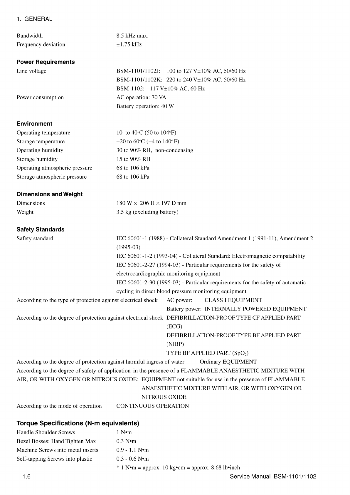
GENERAL
Bandwidth
Frequency
Power
Line
Power
Requirements
voltage
consumption
Environment
Operating
Storage
Operating
Storage
Operating
Storage
temperature
temperature
humidity
humidity
atmospheric
atmospheric
Dimensions
Dimensions
Weight
deviation
and
Weight
pressure
pressure
8.5
kHz
max.
+1.75
kHz
BSM-1101/1102J:
BSM-1101/1102K:
BSM-1102:
AC
operation:
Battery
10
to
40°C
—20
to
30
to
90%
15
to
90%
68
to
106
68
to
106
180 W x
3.5
kg
117
70
operation:
(50
60°C
(—4
RH,
RH
kPa
kPa
206 H x
(excluding
100
to
220
to
240
V+10%
AC,
VA
40
W
to
104°F)
to
140°
F)
non-condensing
197
Dmm
battery)
127
V+10%
V+10%
60
Hz
AC,
AC,
50/60
50/60
Hz
Hz
Safety
Safety
Standards
standard
According
According
According
According
AIR,
OR
According
to
to
to
to
WITH
to
the
the
the
the
the
type
degree
degree
degree
OXYGEN
mode
of
protection
of
protection
of
protection
of
safety
OR
of
operation
against
of
application
NITROUS
IEC
60601-1
(1988) - Collateral
(1995-03)
IEC
60601-1-2
IEC
60601-2-27
electrocardiographic
IEC
60601-2-30
cycling
against
against
in
direct
electrical
electrical
harmful
in
the
OXIDE:
EQUIPMENT
shock | AC
ingress
presence
ANAESTHETIC
NITROUS
CONTINUOUS
Standard
(1993-04) - Collateral
(1994-03) - Particular
monitoring
equipment
(1995-03) - Particular
blood
pressure
monitoring
power:
Battery
shock
DEFIBRILLATION-PROOF
power:
(ECG)
DEFIBRILLATION-PROOF
(NIBP)
TYPE
BF
APPLIED
of
water
of a FLAMMABLE
not
suitable
MIXTURE
OXIDE.
OPERATION
Amendment 1 (1991-11),
Standard:
Electromagnetic
requirements
requirements
equipment
CLASS I EQUIPMENT
INTERNALLY
TYPE
TYPE
PART
(SpO;)
Ordinary
EQUIPMENT
ANAESTHETIC
for
use
in
the
presence
WITH
AIR,
OR
for
the
for
the
POWERED
CF
BF
WITH
Amendment
compatability
safety
of
safety
of
EQUIPMENT
APPLIED
APPLIED
MIXTURE
of
FLAMMABLE
OXYGEN
2
automatic
PART
PART
WITH
OR
Torque
Handle
Bezel
Machine
Specifications
Shoulder
Bosses:
Screws
Self-tapping
1.6
Screws
Hand
into
Screws
Tighten
metal
into
plastic
(N-m
Max
inserts
equivalents)
1
Nem
0.3
Nem
0.9-
1.1
0.3 - 0.6
* | Nem
Nem
Nem
—approx.
10
kgecm — approx.
8.68
İbeinch
service
Manual
BSM-1101/1102
Page 17

1.
GENERAL
BSM-1101
BSM-1102
Front
|
—
Enclosure
Rear
Internal
Enclosure
Support
LI
Assembly,
UR-3496
UR-3500
Assembly
Assembly,
UR-3492
UR-34921
Encoder
Power
with
Pump
Analog
Analog
UR-3495
Board
Switch
Power
Valve
Board
Board
MP-205
|
UR-3493
UR-3494
Digital
Board
PCMCIA
ZB800
Interface
Assembly
Assembly
SpO,
SpO,
Assembly
Board
Assembly
Board
Assembly
Board
Board
Assembly
Board
for
BSM-1101
for
BSM-1102
Assembly
Assembly
Assembly
for
BSM-1101
for
BSM-1102
WS-120P
Recorder
RG-920P
UR-3501
UR-3497
UR-3514
Assembly
UR-3491
—
UR-3502
Drive
Unit
Recorder
Hall
Option
Recorder
Recorder
Interface
Effect
Interface
Power
Digital
Board
Board
Assembly
Board
Assembly
Board
Assembly
Board
Assembly
Assembly
Service
Manual
BSM-1101/1102
1.7
Page 18
1.
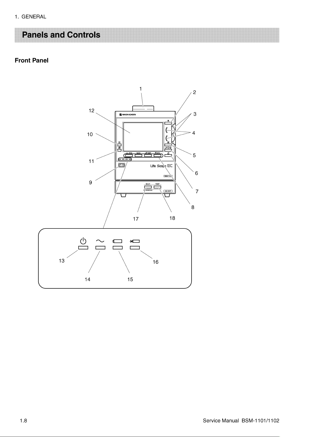
GENERAL
Front
Panel
1.8
Service
Manual
BSM-1101/1102
Page 19
1.
Alarm
2.
Suspend
3.
Function
4.
Function
5.
Review
6.
NIBP
7.
Home
8.
ECG,
hard/soft
^\^
SpO2
e
Name
bar
key
Dial 1 and
Dial
lamp 1 and
key
start/stop
key
SpO,,
key
NIBP
(function)
ECG
NIBP
2
A
and
keys
党
ETC
1.
GENERAL
Description
Red
or
orange
lamp
blinks
according
blinks
in
synchronization
Press
to
temporarily
detection,
Used
2
Lights
Press
Starts
Press
When
displayed
When
keys
respectively.
alarm
recording
for
setting
alarm
when
the
function
to
display
the
or
stops
NIBP
to
display a monitoring
soft
keys
are
function
soft
keys
are
which
call
up
with
suspend
and
limits
dials
List
screen,
measurement.
displayed
keys.
not
displayed
the
ECG,
to
the
QRS.
the
alarm
function
screen
messages.
and
scrolling a list
are
available.
Trend
screen
screen.
on
the
screen,
on
the
SpO,,
NIBP
the
alarm
these
screen,
setting
settings.
alarm
or
trendgraph.
and
Arrhythmia
keys
these
screens and
Green
sound,
function
keys
function
alarm
Recall
as
ETC
lamp
screen.
the
as
hard
screen,
(5
Power
Record
ETC
switch
key
9.
10.
S
11.
Record
setup
key
12.
Display
13.
AC
power
14.
AC
15.
Battery
16.
Battery
7
.
MULTI
18.
TEMP
lamp
operation
operation
charging
τικ
ke
?
key
lamp
lamp
lamp
Push
to
turn
the
monitor
press
and
hold
the
Press
to
start
or
stop
Press
to
select a combination
the
optional
5.5
inch
Lights
Lights
Lights
Lights
Press
socket.
Press
color
when
when
when
or
to
call
(Refer
to
call
recorder.
LCD.
monitor
operating
operating
slowly
up
to
up
the
the
switch
recording
power
blinks
setting
the
Appendix.)
TEMP
power
for
on
AC
on
battery
when
on
at
least
when
(pattern)
is
on.
power.
charging.
screen
SETUP
or
power.
of
screen.
off.
one
second.
using
of
recording
the
parameter
When
the
optional
(Refer
turning
the
recorder.
waveform(s)
connected
to
the
Appendix.)
power
when
to
the
off,
using
MULTI
Service
Manual
BSM-1101/1102
1.9
Page 20
1.
GENERAL
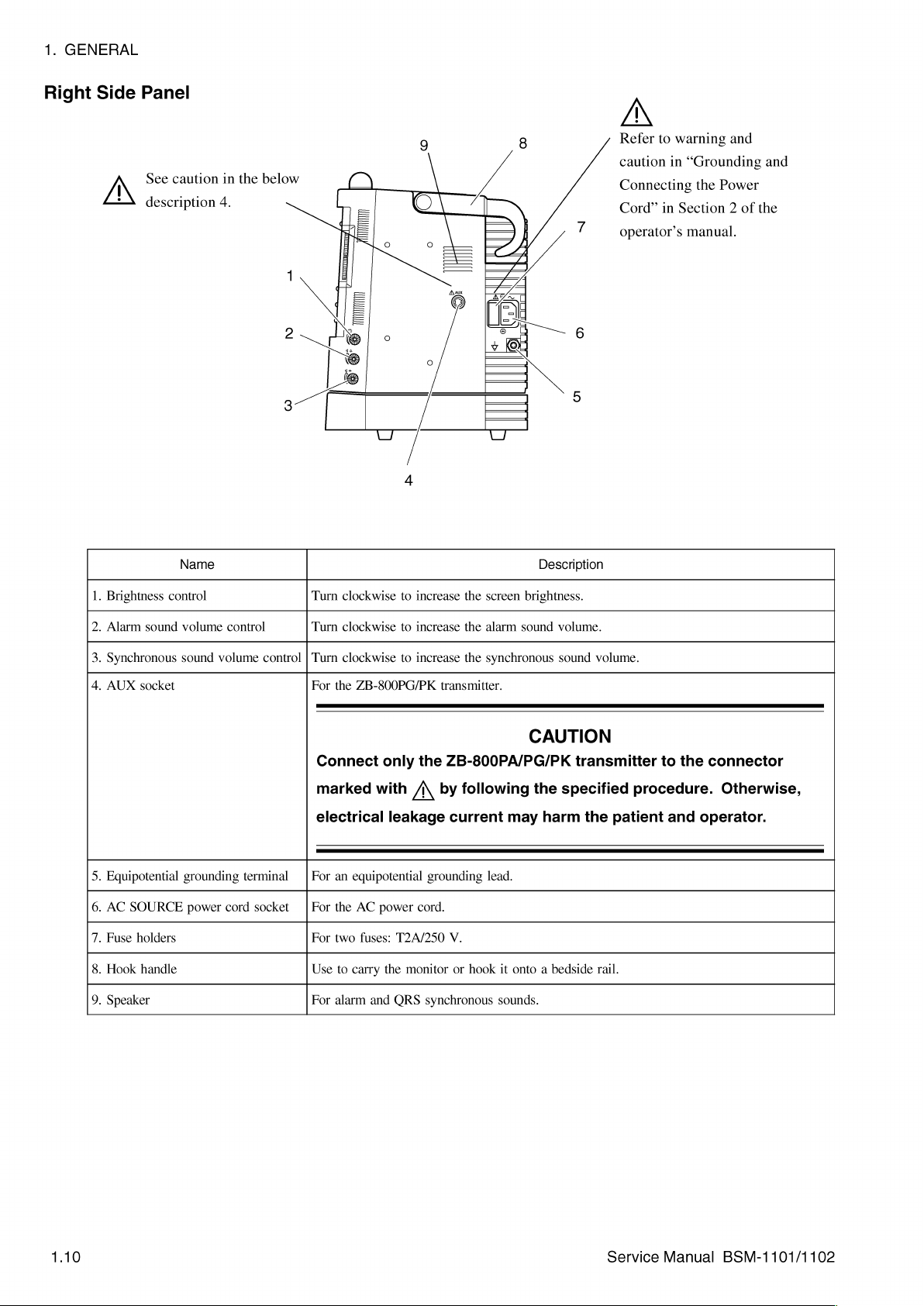
Right
Side
Panel
See
caution
description
in
4.
the
below
4
A
Refer
to
warning
caution
Connecting
Cord”
operator’s
in
in
Section
and
“Grounding
the
Power
2
of
manual.
and
the
control
sound
socket
holders
handle
Name
volume
sound
grounding
power
1.
Brightness
2.
Alarm
3.
Synchronous
4.
AUX
5.
Equipotential
6.
AC
SOURCE
7.
Fuse
8.
Hook
9.
Speaker
control
volume
terminal © |
cord
Turn
Turn
control | Turn
For
Connect
marked
electrical
For
socket | For
For
Use
For
clockwise
clockwise
clockwise
the
ZB-800PG/PK
only
with
leakage
an
equipotential
the
AC
power
two
fuses:
to
carry
the
alarm
and
to
increase
to
increase
to
increase
the
/\
grounding
cord.
T2A/250
monitor
ORS
synchronous
the
screen
brightness.
the
alarm
sound
the
synchronous
transmitter.
ZB-800PA/PG/PK
by
following
current
V.
or
lead.
hook
sounds.
may
it
onto a bedside
Description
volume.
sound
CAUTION
transmitter
the
specified
harm
volume.
the
rail.
to
the
connector
procedure. Otherwise,
patient
and
operator.
1.10
Service
Manual
BSM-1101/1102
Page 21

Left
Side
Panel
A
Refer
to
warning
“General
Section | of
manual.
Safety
1.
and
Information”
the
operator’s
GENERAL
caution
in
in
Refer
to
warning
"General
Section | of
Safety
and
Information”
the
operator’s
caution
manual.
in
in
1.
Paper
2.
Recorder
3.
Cuff
4,
SpO,
5.
ECG
6.
Temp
7.
MULTI
magazine
(option)
socket
socket
socket
socket
socket
Name
release
lever
Push
to
open
2-channel
Connects
Connects
Connects
Connects
Connects
pressure,
the
paper
thermal
to
to
to
to
to
respiration
array
the
NIBP
the
SpO,
the
ECG
the
temperature
the
parameter
or
Description
magazine.
recorder.
air
hoses.
connection
connection
probe
to
be
CO,.
(Refer
cord.
cord
for
cable.
measured
to
the
measuring
(Refer
to
from
invasive
Appendix.)
ECG.
the
Appendix.)
blood
Service
Manual
BSM-1101/1102
Page 22

1.
GENERAL
Rear
Panel
NIHON
πο
KOHDEN
ση
See
Caution
below
2
3
о
4
in
the
description
1.
==
card
Name
slot
For a OI-101P
network
card.
1.
PC
Description
2.
PC
card
3.
PC
card
4.
Battery
lamp
eject
pack
button
holder
e
Use
only
e
Do
not
is
lit.
Lights
while
Press
to
eject
Remove
the
press
This
data
the
cover
the
may
is
PC
and
Nihon
the
damage
read
card.
insert
PC
from
Kohden
card
or
written
the
battery
CAUTION
card.
eject
the
PC
to
the
pack.
button
card
and
PC
card.
while
monitor.
the
PC
card
lamp
Service
Manual
BSM-1101/1102
Page 23
1.
GENERAL
Storage
Follow
Before
1.
Disconnect
2.
Remove
3.
Cover
4.
If
5.
Make
duration
Storage
Storage
these
procedures
storing
the
the
the
instrument
possible,
sure
the
of
temperature
humidity
instrument
the
power
battery
store
the
storage
the
storage:
when
storing
for a long
cord
from
from
the
instrument.
with a dust
instrument
place
meets
—20
to
15
to
the
cover.
in
60°C
90%
or
transporting
time,
perform
instrument.
its
original
the
following
(-4
to
130°F)
RH,
non-condensing
the
instrument.
the
following
shipping
storage
steps:
container.
conditions
for
the
Transport
To
transport
1.
Disconnect
2.
Remove
3.
Cover
4.
If
the
the
the
instrument
possible,
instrument,
the
power
cord
battery
from
with a dust
transport
the
perform
the
from
the
the
instrument.
cover.
instrument
following
steps:
instrument.
in
its
original
shipping
container.
Service
Manual
BSM-1101/1102
1.13
Page 24
1.
GENERAL
The
four
soft
keys,
When
the
ECG,
SpO,,
screens,
When
any
display
key
functions.
screen,
LEAD
In
this
NAME]
keys
on
depending
normal
NIBP,
respectively.
screen
appears
the
NAME
manual,
key).
ECG
at
For
setting
(ECG
soft
the
front
panel
on
the
monitoring
and
ETC
other
than
the
bottom
example,
screen
waveform
keys
are
below
screen
display.
screen
hard
keys,
the
normal
of
the
screen
when
the
displays
lead
indicated
the
screen
is
displayed,
and
call
monitoring
and
ECG
key
and
the
selector
by
brackets
up
the
is
ECG
soft
function
the
four
the
ECG,
screen
four
keys
pressed
key
key).
(for
example,
as
either
hard
keys
function
SpO,,
NIBP,
appears, a soft
correspond
at
the
normal
function
changes
the
[LEAD
keys
or
as
the
and
ETC
key
to
the
soft
monitoring
to
Service
Manual
BSM-1101/1102
Page 25

Upgrading
erases
settings
The
instrument
changing a language
inserted
checks
contains a newer
automatically
new
one.
the
same
confirmation
system
the
all
system
so
they
into
its
the
program
replaces
If
the
or
older
message
program,
system
can
uses a program
memory
version
program
than
the
software
and
individual
be
re-entered
on
screen.
card
card
for a system
of
the
its
current
card
contains a system
the
one
appears
instrument
CAUTION
card
for
When
slot
during
system
system
in
the
on
the
continues
and
changing
bed
settings.
after
the
upgrading
the
instrument
the
booting
program
program
program
instrument,
screen.
If
the
boot-up
the
language
Write
down
software
its
system
detects
stage
or
language.
or
language,
or
language
program
however, a replacement
the
program
process.
upgrade.
software
that a program
after
it
If
the
the
instrument
information
whose
version
card
does
1s
program
1.
GENERAL
on
these
and
turned
number
not
screen
card
on,
it
card
with
the
is
contain
1s
a
How
to
Upgrade
Instrument
Software
and
Language
System
Change
on
Screen
the
a
In
the
system
first
deletes
checks
whether
completely
information
process.
to
1.
2.
3.
4.
After
check
the
Write
down
Insert
the
Turn
on
self-check
Confirm
software
the
old
system
the
data
deleted,
from
the
it
the
the
data
instrument.
the
system
program
instrument.
programs.
that
the
upgrading
software
in
the
copies
the
program
is
successfully
settings
card
into
The
The
new
system
or
language
or
language
system
card
Diagnostic
ROM
new
version
to
the
copied,
and
individual
the
PC
card
instrument
software
changing
is
completely
of
system
it
slot
performs
Check
version
stored
in
the
system
ROM
and
performs
bed
settings
of
the
instrument.
the
and
System
number
process,
its
system
deleted.
program
then
the
self-check
of
upgrading
Setup
appears.
the
instrument
ROM.
When
or
checks
the
instrument.
process
screen
Then
the
data
language
the
copy
programs
and
appears.
it
is
Service
Manual
BSM-1101/1102
Page 26

Section
2
Troubleshooting
General
How
Power-Related
DisplayProblems..........................................
SsoundProblems................................
Key
Recording
ECG
spO,Problems..............................................
Non-Invasive
Signal
Information
to
TroubleSNOOt
Operation
Problems
Problems
Noise
.4
..................
Problems
Problems
..............
.4
Blood
Pressure
Problems
.4
eee
e
sise
Problems
2.1
ii
neee
eeeaeeeeeeneeeneeneenenenenenanın
eee
rara
ii
PKR K RKK
i
2.2
2.3
2.4
2.5
2.6
2.7
2.9
2.10
2.11
2.14
Service
Manual
BSM-1101/1102
2C.1
Page 27

Use
this
section
troubleshooting
e
Power-related
e
Display
e
Sound
e
Key
operation
e
Recording
e
ECG
e
SpO,
e
NIBP
to
locate,
tables
identify,
in
this
and
section
solve
are
an
divided
2.
TROUBLESHOOTING
instrument
problem.
into 8 general
The
problem
areas:
Service
Manual
BSM-1101/1102
2.1
Page 28

2.
TROUBLESHOOTING
1.
Determine
2.
Inthe
3.
Do
the
4.
Ifthe
criteria.
5.
If
none
Corporation
Before
contacting
technical
Sheet
of
on
Sheet
this
the
Nihon
best
(the
manual),
problem.
to
Kohden
support.
which
“Problem”
action
recommended
problem
of
the
actions
dealer.
support,
original
Nihon
Kohden
Corporation
troubleshooting
column,
is
not
find
solved,
solve
Nihon
please
is
and
Send
Kohden
complete a copy
provided
if
possible,
the
completed
Corporation
the
in
the
do
the
problem,
at
or
your
table
to
item
that
“Action”
the
action
NOTE
Corporation
the
end
provide
copy
or
distributor
use.
matches
column.
for
the
next
contact
of
of
Section
your
the
additional
of
the
your
distributor.
the
problem.
possible
nearest
or
your
Maintenance
6,
detailed
Maintenance
provide
cause
or
Nihon
Kohden
distributor
for
Check
“Maintenance,”
information
Check
This
helps
you
with
the
2.2
Service
Manual
BSM-1101/1102
Page 29
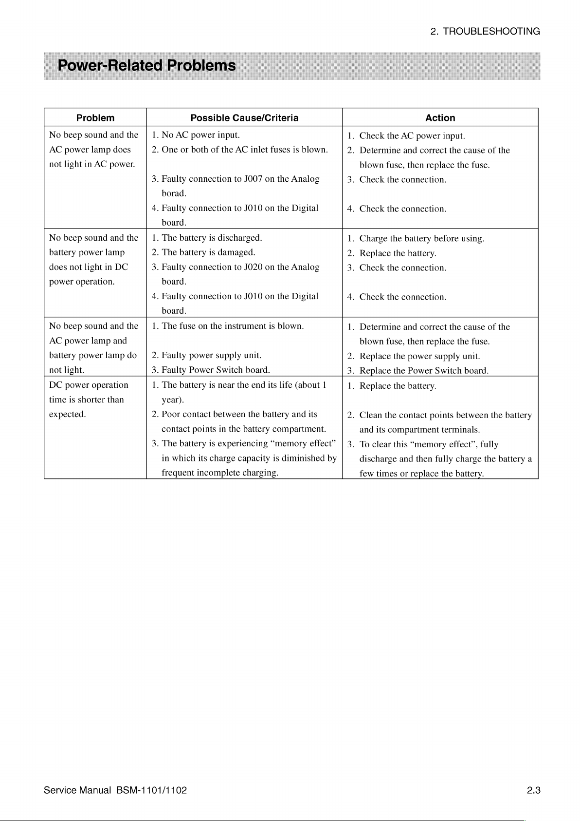
Problem
No
beep
sound
AC
power
not
light
in
No
beep
sound
battery
does
power
No
AC
battery
not
DC
time
expected.
power
not
light
operation.
beep
sound
power
power
light.
power
is
shorter
and
the
lamp
does
AC
power.
and
the
lamp
in
DC
and
the
lamp
and
lamp
do
operation
than
Possible
1.
No
AC
power
input.
.
One
or
both
of
the
.
Faulty
connection
borad.
.
Faulty
connection
board.
1.
The
battery
is
discharged.
2.
The
battery
is
damaged.
3.
Faulty
connection
board.
.
Faulty
connection
board.
.
The
fuse
on
the
instrument
2.
Faulty
power
supply
3.
Faulty
Power
Switch
.
The
battery
is
near
year).
.
Poor
contact
contact
.
The
battery
in
which
frequent
between
points
in
is
experiencing
its
charge
incomplete
the
Cause/Criteria
AC
inlet
fuses
to
J007
on
the
to
JO10
on
the
to
J020
on
the
to
JO10
on
the
is
blown.
unit.
board.
the
end
its
life
the
battery
battery
capacity
charging.
compartment.
“memory
is
diminished
is
blown.
Analog
Digital
Analog
Digital
(about
and
its
effect”
1.
Check
the
.
Determine
blown
fuse,
.
Check
the
.
Check
the
1.
Charge
2.
Replace
3.
Check
the
.
Check
the
.
Determine
blown
fuse,
2.
Replace
3.
Replace
1
.
Replace
.
Clean
the
and
its
compartment
.
To
clear
by
discharge
few
times
AC
power
and
then
connection.
connection.
the
battery
the
battery.
connection.
connection.
and
then
the
power
the
Power
the
battery.
contact
this
“memory
and
then
or
replace
2.
TROUBLESHOOTING
Action
input.
correct
correct
the
replace
before
the
replace
supply
Switch
points
terminals.
effect”,
fully
the
cause
the
using.
cause
the
unit.
board.
between
charge
battery.
of
fuse.
of
fuse.
fully
the
the
the
the
battery
battery
a
Service
Manual
BSM-1101/1102
2.3
Page 30
2.
TROUBLESHOOTING
No
display
light
up.
No
display,
and
the
operational.
No
display,
the
NIBP
operational.
Fine
vertical
the
LCD.
Some
randomly
the
LCD
not
lighting
maximum
Some
randomly
the
LCD
6
with
brightness
considered
The
characters
waveforms
The
display
brightness
make
it
The
instrument
the
system
itself.
No
waveform
Waveforms
not
displayed.
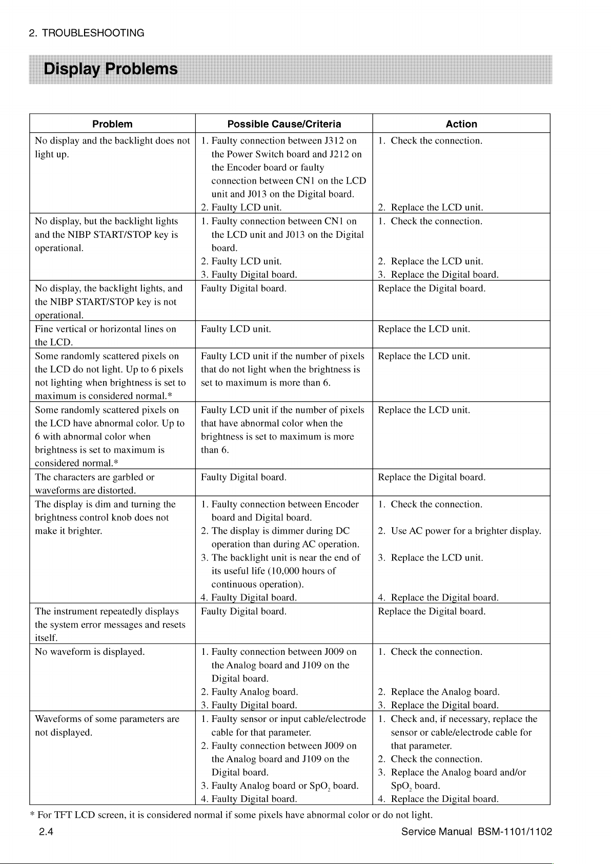
*
For
TFT
2.4
Problem
and
but
NIBP
START/STOP
the
START/STOP
or
do
not
when
is
considered
have
abnormal
abnormal
is
set
normal.*
are
is
dim
control
brighter.
error
is
of
some
LCD
the
backlight
the
backlight
backlight
horizontal
scattered
light.
scattered
color
to
are
distorted.
repeatedly
messages
displayed.
screen,
lights,
key
Up
to 6 pixels
brightness
normal.*
color.
when
maximum
garbled
and
turning
knob
does
parameters
it
is
does
not
lights
key
is
and
is
not
lines
on
pixels
on
is
set
to
pixels
on
Up
to
is
or
the
not
displays
and
resets
are
considered
Possible
1.
Faulty
the
Power
the
Encoder
connection
unit
and
2.
Faulty
1.
Faulty
the
LCD
board.
2.
Faulty
3.
Faulty
Faulty
Digital
Faulty
LCD
Faulty
LCD
that
do
not
set
to
maximum
Faulty
LCD
that
have
brightness
than
6.
Faulty
Digital
1.
Faulty
board
and
2.
The
display
operation
3.
The
backlight
its
useful
continuous
4.
Faulty
Faulty
Digital
1.
Faulty
the
Analog
Digital
2.
Faulty
Analog
3.
Faulty
1.
Faulty
cable
for
2.
Faulty
the
Analog
Digital
3.
Faulty
Analog
4.
Faulty
normal
if
some
Cause/Criteria
connection
Switch
board
between
J013
on
the
LCD
unit.
connection
unit
and
LCD
unit.
Digital
board.
board.
unit.
unit
if
the
light
when
is
more
unit
if
the
abnormal
is
connection
life
Digital
connection
board.
Digital
sensor
that
connection
board.
Digital
color
set
to
maximum
board.
Digital
is
dimmer
than
during
unit
(10,000
operation).
board.
board.
board
board.
board.
or
input
parameter.
board
board
board.
pixels
between
board
or
between
J013
between
board.
is
between
and
between
and
have
J312
and
J212
faulty
CNT
on
the
Digital
number
the
number
board.
CN1
on
the
of
brightness
than
6.
of
when
the
is
Encoder
during
AC
operation.
near
the
hours
of
J009
J109
on
cable/electrode
J009
J109
on
or
SpO,
abnormal
on
on
LCD
on
Digital
pixels
15
pixels
more
DC
end
of
on
the
on
the
board.
color
Action
1.
Check
the
connection.
2.
Replace
1.
Check
2.
Replace
3.
Replace
Replace
Replace
Replace
Replace
Replace
1.
Check
2.
Use
3.
Replace
4.
Replace
Replace
1.
Check
2.
Replace
3.
Replace
1.
Check
sensor
that
2.
Check
3.
Replace
SpO,
4.
Replace
or
do
the
the
the
the
the
the
the
AC
power
the
the
and,
or
parameter.
the
board.
not
light.
Service
the
LCD
unit.
connection.
the
LCD
unit.
the
Digital
Digital
LCD
LCD
LCD
Digital
connection.
the
LCD
the
Digital
Digital
connection.
the
Analog
the
Digital
if
cable/electrode
connection.
the
Analog
the
Digital
Manual
board.
board.
unit.
unit.
unit.
board.
for a brighter
unit.
board.
board.
board.
board.
necessary,
board
board.
BSM-1101/1102
display.
replace
cable
for
and/or
the
Page 31

Problem
No
sound.
No
sound,
except
hissing
The
The
volume
synchronous
volume
operational.
sound.
sound
alarm
control
control
is
sound
for
muffled.
and/or
sound
are
not
1.
Faulty
Digital
2.
Faulty
3.
Faulty
Faulty
a
board
1.
The
instrument
2.
The
way.
1.
Faulty
2.
Faulty
Possible
connection
board
speaker.
Digital
connection
and
J114
on
speaker
volume
on
is
control
Digital
Encoder
Cause/Criteria
between
and
J114
on
board.
between
the
speaker.
the
right
blocked.
is
not
board.
board.
JO14
the
J014
side
turned
on
the
speaker.
on
the
Digital
of
the
up
all
the
1.
Check
2.
Replace
3.
Replace
Check
1.
Remove
2.
Adjust
1.
Replace
2.
Replace
the
the
the
the
connection.
the
the
the
the
2.
Action
connection.
speaker.
Digital
volume.
Digital
Encoder
object
board.
blocking
board.
TROUBLESHOOTING
the
speaker.
board.
Service
Manual
BSM-1101/1102
2.5
Page 32

2.
TROUBLESHOOTING
No
keys,
switch,
Some
(excluding
panel
Power
Function
Problem
except
are
operational.
keys
are
keys
and
Power
switch
dials
the
Power
not
operational
on
the
switch).
is
not
operational.
are
not
1.
2.
3.
1.
connector | 2.
1.
2.
operational. | 1.
2.
3.
Possible
Faulty
panel
and
Faulty
Faulty
Faulty
Faulty
Faulty
Faulty
Faulty
panel
and
Faulty
Faulty
Cause/Criteria
connection
JO17
on
Digital
membrane
membrane
Digital
Power
Digital
connection
Encoder
Digital
JO18
board.
board.
Switch
board.
on
board.
board.
between
the
Digital
switch
switch
board.
between
the
Digital
the
key
board.
assembly.
assembly.
the
key
board.
1.
2.
3.
1.
2.
1.
2.
1.
2.
3.
Check
Replace
Replace
Replace
Replace
Replace
Replace
Check
Replace
Replace
the
connection.
the
Digital
the
membrane
the
membrane
the
Digital
the
Power
the
Digital
the
connection.
the
Encoder
the
Digital
Action
board.
board.
Switch
board.
board.
board.
assembly.
switch
assembly.
board.
2.6
Service
Manual
BSM-1101/1102
Page 33

Missing
Fixed
lines
Paper
causing
Abnormally
sound
No
Problem
dots
lengthwise
along
the
does
not
skewing.
loud
of
recorder
recording
in
the
recording.
straight
recording.
feed
properly, | 1.
rotating
unit
on
the
paper.
1.
2.
Faulty
2.
3.
4.
5.
Faulty
motor.
1.
2.
3.
4.
5.
Possible
Dirty
thermal
Faulty
thermal
thermal
Dirty
gear.
Faulty
gear.
Dirty
platen
Damaged
If
the
recorder
constant
between:
e
e
e
e
The
paper
Faulty
Faulty
board,
Interface
Faulty
Digital
Faulty
e
e
e
e
speed,
the
recorder
Recorder
J515
on
J415
on
J315
on
J215
on
J115
on
and
JO15
platen
heat-sensitive
is
facing
thermal
recorder
Recorder
board
+24 V output
board.
connection
the
recorder
Recorder
J515
on
J415
on
J315
on
J215
on
J115
on
and
JO15
Cause/Criteria
head.
head.
head.
roller.
platen
roller.
unit
there
unit
Power
the
Recorder
the
Recorder
the
Recorder
the
Recorder
the
Recorder
on
the
roller
or
the
head.
unit,
Digital
or
unit
Power
the
Recorder
the
Recorder
the
Recorder
the
Recorder
the
Recorder
on
the
motor
rotates
is a faulty
and
J615
board
Power
Digital
Digital
Interface
Interface
Digital
side
wrong
Digital
between:
Digital
gear.
of
Recorder
board,
from
and
J615
board
Power
Digital
Digital
Interface
Interface
board
the
way.
board.
JO15
board
on
board
recording
Power
Recorder
on
on
board
at
a
connection
the
and
board
board
and
board
board
the
the
and
board
board
and
board
board
2.
TROUBLESHOOTING
Action
1.
Clean
the
thermal
2.
Replace
Replace
1.
Clean
2.
Replace
3.
Clean
4.
Replace
5.
Check
Replace
unit.
1.
Make
detection
the
2.
Replace
3.
Replace
board.
4.
Check
necessary,
5.
Check
the
the
thermal
the
the
the
the
the
the
platen
sure
paper.
the
the
the
the
gear.
platen
connections.
mark
+24 V output
replace
connections.
thermal
head.
gear.
roller.
platen
roller
the
side
faces
thermal
recorder
head.
head.
roller.
or
with
the
up
when
head.
unit
and,
the
Digital
the
recorder
black
or
faulty
inserting
if
board.
Service
Manual
BSM-1101/1102
2.7
Page 34
2.
TROUBLESHOOTING
Out
of
there
tray
and
during
Paper
automatically,
be
made
paper
the
RECORD
Paper
automatically,
cannot
recording
pulled
1s
pressed.
For
page-dependent
such
does
page.
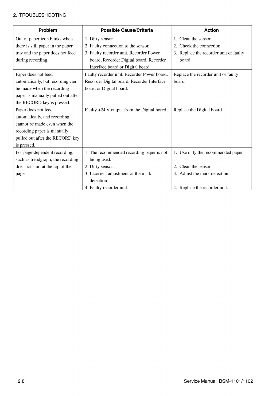
Problem
paper
icon
is
still
paper
the
paper
recording.
does
not
when
is
manually
does
not
be
made
paper
out
after
as
trendgraph,
not
start
blinks
in
does
feed
but
recording
the
pulled
key
is
feed
and
even
is
manually
the
at
the
when
the
paper
not
feed
recording
out
pressed.
recording
when
the
RECORD
recording,
the
recording
top
of
the
1.
Dirty
2.
Faulty
3.
Faulty
board,
Interface
Faulty
can
after
Recorder
board
Faulty
key
1.
The
being
2.
Dirty
3.
Incorrect
detection.
4.
Faulty
Possible
sensor.
connection
recorder
Recorder
board
recorder
or
+24 V output
recommended
Digital
Digital
used.
sensor.
adjustment
recorder
unit,
board,
board.
Cause/Criteria
to
the
sensor.
unit,
Recorder
Digital
board,
or
Digital
Recorder
from
unit.
board.
Power
Recorder
the
Digital
recording
of
the
mark
paper
Power
Recorder
board,
Interface
board.
is
not
Action
1.
Clean
the
sensor.
2.
Check
the
connection.
3.
Replace
board.
Replace
board.
Replace
1.
Use
2.
Clean
3.
Adjust
4.
Replace
the
the
only
the
the
the
recorder
recorder
Digital
the
recommended
sensor.
mark
the
recorder
unit
or
unit
or
faulty
board.
detection.
unit.
faulty
paper.
2.8
Service
Manual
BSM-1101/1102
Page 35

ECG
its
AC
interference
waveform.
CHECK
message
recommendations
Operator’s
not
PACING
appears
recommendations
Operator’s
not
Problem
baseline
normal
position.
noise-like
LEADS
appears
correct
message
and
correct
is
out
on
the
and
Manual
the
problem.
the
Manual
the
problem.
in
do
in
do
of
the
the
the
1.
If
the
input,
2.
If
the
ECG
1.
Poor
position.
2.
Faulty
3.
Electrical
electric
4.
If
the
is
set
faulty.
5.
If
the
disconnected,
If
the
leads
1.
Faulty
2.
Faulty
panel.
3.
Faulty
board
4.
Faulty
5.
Faulty
1.
Spike
waveform.
2.
If
the
signal
input,
Possible
baseline
the
Analog
baseline
lead
is
changed,
electrode
electrode
interference
blanket,
trouble
to
trouble
message
are
message
persists
monitoring
persists
the
does
short-circuited:
electrode
ECG
input
connection
and
J109
Analog
Digital
or
narrow
from
the
the
Analog
is
not
board
does
not
to
skin
leads
near
mode,
Analog
not
leads
connector
between
on
the
board.
board.
QRS
still
appears
AX-800P
board
normal
Cause/Criteria
the
contact
or
emitting
the
when
after the
disappear
or
Digital
complex
even
1s
faulty.
change
even
Analog
or
bad
electrode
source,
instrument.
the
ECG
the
Analog
electrode
board
is
when
electrode
on
the
J009
on
board.
on
when a normal
Vital
Sign
is
faulty.
when
ECG
when
board
is
electrode
cable.
such
setup
board
leads
faulty.
the
cable.
connector
the
Analog
the
ECG
Simulator
is
not
.
Replace
the
faulty.
as
an
setting . Replace
is
are
electrode
ECG
is
.
Replace
.
Refer
correct
.
Replace
electrode
.
If
possible,
instrument
.
Replace
.
Check
electrode
.
Replace
.
Check
4.
Replace
.
Replace
.
Turn
.
Replace
2.
the
the
to
the
this
the
cable.
the
the
and,
leads
the
the
connection.
the
the
pacing
the
TROUBLESHOOTING
Action
Analog
Analog
Operator’s
problem.
electrode
place
away
Analog
Analog
if
ECG
Analog
Digital
mode
Analog
board.
board.
leads
the
patient
from
such
board.
board.
necessary,
or
electrode
input
board.
board.
off.
board.
Manual
replace
connector.
to
or
and
the
source.
the
cable.
Service
Manual
BSM-1101/1102
2.9
Page 36

2.
TROUBLESHOOTING
Problem
PROBE
message
continuously
displayed.
PROBE
message
continuously
displayed,
when
SDO2
are
PULSE
SEARCH
message
continuously
displayed.
INSERT
CONNECTOR
message
continuously
displayed.
SpO2
MODULE
ERROR
message
appears.
1102
other
probes
used.
only)
OFF
is
OFF
is
even
is
is
(BSM-
1.
The
SpO2
probe
2.
The
external
1.
Faulty
2.
Faulty
3.
Faulty
J109
on
4.
Faulty
board.
5.
Faulty
6.
Faulty
7.
Faulty
1.
The
patient’s
probe.
2.
If
the
used,
1.
If
this
turned
If
this
message
connector
connector
2.
Faulty
3.
Faulty
4.
Faulty
J109
on
5.
Faulty
board.
6.
Faulty
7.
Faulty
8.
Faulty
SpO2
hardware
light
SpO2
probe.
SpO2
input
connection
the
Digital
connection
SpO2
board.
Analog
Digital
pulse
same
message
the
SpO2
message
on,
the
is
from
the
on
the
SpO2
probe.
SpO2
input
connection
the
Digital
connection
SpO2
board.
Analog
Digital
malfunction.
Possible
is
is
board.
board.
board
appears
SpO2
continuously
probe
connector
board.
board.
Cause/Criteria
not
correctly
too
bright.
connector
between
board.
between
is
too
weak
appears
is
faulty.
immediately
board
is
inserted
panel,
connector
between
board.
between
attached
on
the
J009
on
the
SpO2
to
when
is
faulty.
displayed
then
on
the
JOO9
on
the
SpO2
to
connector
the
Analog
board
be
picked
other
SpO2
after
even
into
the
there
connector
the
Analog
board
the
and
up
the
when
SpO2
is
a:
and
patient.
panel.
board
the
Analog | 4.
by
the
probes
power
is
the
input
panel.
board
the
Analog | 5.
1.
2.
1.
2.
and
SpO2 | 1.
are
SpO2
and
3.
5.
6.
7.
2.
2.
3.
4.
6.
7.
8.
Replace
Refer
the
correct
procedure.
Cover
of
external
Replace
Replace
Check
Check
Replace
Replace
Replace
Refer
correct
Replace
1.
Replace
Replace
Replace
Check
Check
Replace
Replace
Replace
to
the
probe
the
probe
light.
the
the
the
connection.
the
connection.
the
the
the
to
the
this
problem.
the
the
SpO2
the
SpO2
the
SpO2
the
connection.
the
connection.
the
SpO2
the
Analog
the
Digital
the
SpO2
Action
Operator’s
attachment
to
reduce
SpO2
probe.
SpO2
input
SpO2
board.
Analog
Digital
Operator’s
SpO2
board.
board.
board.
board.
probe.
input
board.
board.
board.
board.
Manual
connector.
Manual
connector.
the
for
effect
to
2.10
Service
Manual
BSM-1101/1102
Page 37

The
value
Cuff
the
not
Problem
measured
is
Suspicious.
does
not
error
message
appear.
NIBP
inflate
does
1.
2.
3.
4.
5.
and | 1.
2.
3.
Possible
Cuff
is
not
patient’s
Cuff
is
wrong
Patient
Accuracy
NIBP
Air
Loose
internal
Blocked
internal
Hose,
moves
self
leak
in
connection
air
connection
air
cuff,
properly
limb.
size.
during
of
the
check
the
NIBP
tube.
tube.
or
internal
Cause/Criteria
wrapped
measurement.
Calibration
is
out
module.
between
between
of
air
around
(1)
the
specified
hose
hose
tube
the
item
of
and
cuff
and
is
punctured.
the
range.
or
cuff
or | 2.
1.
Refer
the
cuff
limb.
2.
Use
Operator’s
correct
3.
Stop
4.
Replace
5.
Check
of
the
replace
1.
Check
Check
3.
Replace
to
the
correctly
the
correct
Manual
cuff
the
patient
the
the
internal
instrument
the
the
connection.
the
connection.
the
2.
TROUBLESHOOTING
Action
Operator’s
around
cuff
size.
to
determine
size
for
the
from
moving.
Analog
air
damaged
air
and,
tubes
board.
tube
if
or
Analog
part.
Manual
the
patient’s
Refer
patient.
connections
necessary,
board.
to
to
the
wrap
the
If
the
pump
motor
rotates
and
the
recorder
operational,
4.
Faulty
board
5.
Faulty
board
6.
Faulty
7.
CHECK
HOSE
measurement.
NIBP
message
measurement.
CUFF
message
AMP
ERROR
during
AND
during
Faulty
If
the
1.
Faulty
board
2.
Faulty
board
3.
Faulty
If
the
4.
Faulty
board
5.
Faulty
6.
Faulty
The
offset
check
there
connection
and
connection
and
Analog
Digital
other
monitored
connection
and
connection
and
Analog
other
monitored
connection
and
Digital
Analog
value
is
out
of
J109
J119
J109
J119
J109
of
the
is
a:
between
on
the
between
on
the
board.
board.
parameters
between
on
the
between
on
the
board.
parameters
between
on
the
board.
board.
the
NIBP
specified
JOO9
Digital
JO19
Digital
J009
Digital
J019
Digital
J009
Digital
item
range.
board.
board.
are
board.
board.
are
board.
of
unit
on
the
Analog | 4.
on
the
Analog | 5.
normal:
on
the
Analog | 1.
on
the
Analog | 2.
incorrect:
on
the
Analog | 4.
the
self
is
Check
Check
6.
Replace
7.
Replace
Check
Check
3.
Replace
Check
5.
Replace
6.
Replace
Replace
the
connection.
the
connection.
the
the
the
connection.
the
connection.
the
the
connection.
the
the
the
Analog
Analog
Digital
Analog
Digital
Analog
board.
board.
board.
board.
board.
board.
Service
Manual
BSM-1101/1102
2.11
Page 38

2.
TROUBLESHOOTING
CHECK
HOSE
measurement.
CHECK
HOSE
measurement.
CHECK
HOSE
measurement.
CHECK
HOSE
measurement.
Problem
CUFF
message
CUFF
message
CUFF
message
CUFF
message
AND
during
AND
during
AND
during
AND
during
1.
Blocked
internal
2.
Accuracy
NIBP
self
Accuracy
self
check
If
the
results
Deflation
the
valve
circuit
is
If
the
results
NIBP
self
1.
Loose
internal
2.
Blocked
internal
3.
Hose,
cuff
4.
If
the
pump
is
not
operational,
power
Possible
connection
air
tube.
of
the
check
of
the
Calibration
is
out
of
of
the
items
of
the
operation
faulty.
of
the
check
is
connection
air
tube.
connection
air
tube.
or
internal
motor
supply
unit
Cause/Criteria
between
Calibration
is
out
the
specified
Deflation
NIBP
or
the
Inflation
ERROR:
between
between
air
rotates
the
is
faulty.
hose
(2)
of
the
specified
(2)
item
range.
Speed
self
check
pump
and
Speed
hose
hose
tube
is
but
the
+24 V supply
and
cuff
item
of
the
range.
of
the
NIBP | Replace
and
Step
are
OK,
valve
driving
item
of
the
and
cuff
or
and
cuff
punctured.
recorder
from
the
or | 1.
2.
Replace
1.
or | 2.
3.
unit | 4.
Check
Replace
the
the
Check
Check
Replace
Replace
the
connection.
the
Analog
Analog
Analog
the
connection.
the
connection.
the
damaged
the
power
Action
board.
board.
board.
part.
supply
unit.
If
the
pump
motor
rotates
and
the
recorder
operational,
5.
Faulty
board
6.
Faulty
board
7.
Faulty
8.
Faulty
9.
CHECK
HOSE
measurement.
CUFF
message
AND
during
Faulty
If
the
screen
the
instrument
generator:
1.
Loose
internal
2.
Blocked
internal
3.
Hose,
4.
Faulty
there
connection
and
J109
connection
and
J119
pump.
Analog
Digital
pressure
of
the
NIBP
connection
air
connection
air
cuff
or
Analog
is
a:
between
on
the
between
on
the
board.
board.
displayed
self
is
inflated
between
tube.
tube.
internal
board.
J009
Digital
J019
Digital
on
the
check
by
an
hose
between
air
tube
on
board.
on
board.
Calibration
is
not
stable
external
and
hose
is
punctured.
unit
the
Analog | 5.
the
Analog | 6.
(1)
after
pressure
cuff
or
and
cuff
is
Check
the
connection.
Check
the
connection.
7.
Replace
8.
Replace
9.
Replace
1.
Check
or
2.
Check
3.
Replace
4.
Replace
the
pump.
the
Analog
the
Digital
the
connection.
the
connection.
the
damaged
the
Analog
board.
board.
part.
board.
2.12
Service
Manual
BSM-1101/1102
Page 39

Usually
period.
Usually
measurement
Problem
long
long
zeroing
period.
Possible
.
Sudden
temperature
to
expand/contract.
.
If
change
supply
faulty.
1.
Patient
.
Loose
internal
.
Hose
blocked.
4.
Hose,
.
Faulty
change
drift
and
the
instrument
in
unit,
moves
connection
air
to
cuff
cuff
Analog
Cause/Criteria
in
operating
can
cause
the
hose
or
did
not
environment
Analog
tube.
or
board
during
between
or
internal
internal
board.
measurement.
environment
the
sensor
temperature
air
tubes
to
experience a sudden
temperature,
or
hose
air
tube
air
tube
Digital
and
connection
is
punctured.
the
board
cuff
power
is
or
is
.
After a sudden
wait
about
instrument.
.
Replace
board.
1.
Stop
.
Check
.
Check
4.
Replace
.
Replace
the
the
the
the
patient
the
the
2.
TROUBLESHOOTING
Action
change
30
minutes
power
supply
from
connection.
connection.
damaged
Analog
board.
in
temperature,
before
using
unit
moving.
part.
or
faulty
the
Service
Manual
BSM-1101/1102
2.13
Page 40

2.
TROUBLESHOOTING
Electrical
level
e
Line
e
Power
e
Electromagnetic
e
High
e
Static
e
Poor
e
High
e
Bad
e
Patient
To
action,
e
Using a dedicated
e
Grounding
e
Installing a surge
e
Turning
around
e
Making
connector
e
Decreasing
e
Using
e
Establishing
noise
signal
measuring
frequency
supply
radio
frequency
electricity
electrode-to-skin
skin-to-electrode
electrode
conditions,
suppress
such
this
as:
the
off
or
the
instrument,
sure
there
the
correct
patient
can
resemble a problem
instrument.
ripple/surge
interference
emitter
contact
impedance
placement
such
as
anxiety
noise,
you
need
power
supply
instrument
protector
removing
is
no
any
such
loose
high
as
or
skin-to-electrode
electrode
placement
conditions
caused
This noise
and
body
to
identify
line
for
the
frequency
televisions,
bad
contact
impedance
that
are
favorable
by a faulty
can
be
caused
movement
its
source
instrument
or
electromagnetic
mobile
phones,
from
the
to
input
circuit
by:
and
then
take
and
electronic
electrode
measurement
the
energy
to
the
in a low-
necessary
emitters
games
input
2.14
Service
Manual
BSM-1101/1102
Page 41

Section
3
Self
Check,
Errors,
System
Initialization
Set
Up,
and
Diagnostics
General
How
Power-Related
DisplayProblems..........................................
SsoundProblems................................
Key
Recording
ECG
spO,Problems..............................................
Non-Invasive
Signal
Information
to
TroubleSNOOt
Operation
Problems
Problems
Noise
.4
..................
Problems
Problems
..............
.4
Blood
Pressure
Problems
.4
eee
e
sise
Problems
2.1
ii
neee
eeeaeeeeeeneeeneeneenenenenenanın
eee
rara
ii
PKR K RKK
i
2.2
2.3
2.4
2.5
2.6
2.7
2.9
2.10
2.11
2.14
Service
Manual
BSM-1101/1102
3C.1
Page 42

3.
SELF
CHECK,
ERRORS,
SYSTEM
SET
UP,
INITIALIZATION
AND
DIAGNOSTICS
Introduction
Calling
Up
History
the
Error
The
instrument
diagnostic
All
errors
during
operation
The
diagnostic
accessed
Use
this
checks
detected
from
the
screen
has
an
that
during
are
stored
checks,
Diagnostic
to
view
initialization.
1.
With
the
power
off,
Continue
Setup
pressing
screen appears.
automatic
you
can
perform
the
power
in
an
error
history,
Check
the
error
press
the
the
SUSPEND
power
on
error
history
and
and
history
Power
key
on
self
at
any
self
check,
system
System
or
perform
switch
until
check
time.
diagnostic
table
setup
Setup
while
the
Diagnostic
as
well
as a complete
that
you
can
and
initialization
screen.
diagnostic
pressing
checks,
view.
or
system
the
SUSPEND
Check
and
are
and
set
any
setup
System
of
time
and
key.
Service
Manual
BSM-1101/1102
2.
To
monitoring
exit
the
Diagnostic
mode,
Check
press
the
[MONITOR
and
System
Setup
MODE|
screen
key.
and
return
to
the
patient
3.1
Page 43

3.
SELF
CHECK,
ERRORS,
SYSTEM
SET
UP,
INITIALIZATION
AND
DIAGNOSTICS
Power
On
Self
Check
This
self
check
CHECK
If
monitoring
System
The
System
that
PROGRAM
no
error
Setup
following
RAM.
are
written
is
detected,
display
screen
items
is a difference,
If
an
error
message
Boot
ROM.
The
by
the
check
sum
data
with
the
exception
sum
at
the
last
address.
screen
display
may
is
performed
RUNNING
the
appears.
appears.
are
The
memory
on
the
RAM
an
error
appears,
program
technique.
be
abnormal.
every
normal
If
checked
in
to
occurs
the
stored
This
of
the
If
the
values
time
message
operating
an
error
during
the
RAM
the
test
and
the
Digital
in
the
technique
value
the
1s
the
patterns
screen
board
boot
of
the
are
not
Power
appears
mode
detected,
power
is
checked
that
display
is
faulty.
ROM
compares
last
address,
the
same,
switch
during
begins
the
Diagnostic
on
self
by
comparing
were
may
of
the
the
with
an
is
turned
the
power
and
the
check:
read
out
be
abnormal.
Digital
sum
value
the
error
occurs
on.
The
on
self
patient
Check
and
the
test
from
it.
board
is
checked
of
the
prestored
and
check.
patterns
If
there
stored
check
the
If
an
error
Program
checked
stored
check
recorder
If
Clock.
an
by
data
sum
may
error
The
comparing
software
time
of
the
If
an
error
A/D-D/A.
checked
an
error
and
occurs
message
ROM.
the
check
with
at
the
not
message
accuracy
the
time
counter.
instrument
message
The
accuracy
compared
and
appears,
The
program
sum
the
exception
last
address.
work.
appears,
of
interval
If
the
appears,
the
the
stored
technique.
of
If
the
the
real-time
of
the
values
are
return
to
their
the
and
conversion
with
their
instrument
Digital
board
in
This
the
value
the
values
Digital
board
clock
periodic
not
the
default
Digital
board
prestored
may
not
is
the
program
technique
of
the
are
is
of
the
interrupt
same,
values.
or
speed
values.
output
faulty.
last
not
the
faulty.
Digital
an
error
PCMCIA
of
the
If
waveform
ROM
of
compares
address,
same,
board
to
the
value
occurs
board
A/D—D/A
the
values
the
Digital
the
sum
with
the
an
error
is
checked
counted
and
is
faulty.
converter
are
not
signals.
board
value
prestored
occurs
by
the
date
is
the
of
and
by
the
and
same,
is
the
the
3.2
If
an
error
message
EEPROM.
the
check
with
the
last
the
exception
address.
The
sum
automatically
If
an
error
message
appears,
program
technique.
of
the
If
the
values
performs
appears,
the
stored
This
value
are
system
the
Digital
in
technique
of
the
the
not
board
EEPROM
compares
last
the
same,
address,
initialization.
Digital
board
is
faulty.
of
the
the
with
an
error
is
faulty.
service
Digital
sum
value
the
prestored
occurs
Manual
board
is
checked
of
the
stored
check
and
the
instrument
BSM-1101/1102
sum
by
data
at
Page 44

3.
SELF
CHECK,
ERRORS,
SYSTEM
SET
UP,
INITIALIZATION
AND
DIAGNOSTICS
Optional
interface
Backed
the
Version.
initialization
is
Up
backed
The
Interface.
not
Data.
up
data
version
is
If
installed,
installed,
The
is
cleared
of
the
parity
the
instrument
automatically
the
optional
optional
of
and
the
the
backed
interface
default
performed.
up
data
is
checked.
interface
default
data
is
is
used.
If
is
checked.
setting
checked.
an
error
If
is
used.
If
an
occurs,
the
optional
error
system
occurs,
Service
Manual
BSM-1101/1102
3.3
Page 45

3.
SELF
CHECK,
ERRORS,
SYSTEM
SET
The
instrument
faults
UP,
INITIALIZATION
has a continuous
during
operation.
AND
DIAGNOSTICS
self
check
function
that
detects
errors
causing
System
Errors
A
system
happens,
appear.
for
error
occurs
all
operation
These
error
messages
troubleshooting.
when a fatal
of
the
instrument
are
not
fault
stored
is
detected
is
halted
in
the
in
and
error
the
the
system
history
CPU
operation.
error
messages
and
cannot
If
be
this
used
3.4
Service
Manual
BSM-1101/1102
Page 46

3.
SELF
CHECK,
ERRORS,
SYSTEM
SET
UP,
INITIALIZATION
AND
DIAGNOSTICS
Error
Codes
When a fault
error
is
stored
are
only
deleted
the
error
history
error
code
1s
The
message
table:
Error
Code
110
210
220
230
240
250
260
270
280
290
2A0
2BO
2C0
310
410
411
420
430
470
472
480
400
is
detected
in
the
when
is
filled
added.
and
description
Message
WATCH
BUS
ADDRES
ILLEGAL
ZERO
CHK
TRAP
PRIVIEGE
SPRIOUS
UNDEFIND
UNDEFIND
UNDEFIND
OTHER
OS
CPU
(ROM)
WS
(ROM)
CPU
(RAM)
A/D,
D/A
CLOCK
CLK
DATA
E2PROM
OTHER
during
operation
error
history
system
up,
table.
initialization
however,
of
each
Description
DOG _ Interrupt
Bus
error
Address
Illegal
Zero
Check
Trap
Privilege
Undefined
Not
used
Not
used
Not
used
Error
Error
Error
Error
Error
Error
Error
Error
Error
Error
or
during
The
error
is
the
oldest
error
code
from
occurred
error
command
division
command
command
error
interrupt
from
faults
detected
detected
detected
detected
detected
detected
detected
detected
from
faults
the
power
codes
performed.
error
code
are
described
the
watch
when
when
word
is
executed
error
error
occurring
error
occurring
error
other
than
by
the
OS
by
CPU
ROM
by
WS
ROM
by
CPU
RAM
by
A/D
and
by
the real
by
CLOCK
by
EEPROM
other
than
on
stored
in
If
the
memory
is
deleted
in
dog
timer
empty
address
accessing
ones
check
check
check
D/A
check
time
clock
DATA
check
those
self
check,
the
error
space
when a new
the
following
is
the
odd
during
check
described
check
described
the
history
for
selected
address
above
above
Calling
History
Service
Manual
Up
the
Error
BSM-1101/1102
The
Error
board
name,
explanation
history
1.
data
From
MENU]
History
time,
of
error
is
deleted
the
Diagnostic
key.
screen
and
codes,
The
Check
shows
date
the
see
whenever
Check
Menu
the
error
the
previous
system
and
screen
error
history
occurred
are
section,
initialization
System
Setup
appears.
of
the
listed
“Error
is
screen,
instrument.
on
this
screen.
Codes.”
performed.
press
the
The
error
For
The
[CHECK
code,
an
error
3.5
Page 47

3.
SELF
CHECK,
ERRORS,
SYSTEM
SET
UP,
INITIALIZATION
AND
$49
CHECK
DIAGNOSTICS
MENU
HH
2.
From
and
the
Check
Menu
press
the
[CHECK]
screen,
key.
The
press
Error
the
[ITEM
History
J]
key
screen
to
select
appears.
Error
History
3.6
3.
To
4.
To
5.
To
[RETURN]
6.
To
monitoring
view
other
return
return
exit
the
pages
to
the
Check
to
the
Diagnostic
key.
Diagnostic
mode,
press
of
Menu
Check
the
the
error
history,
screen,
Check
and
[MONITOR
press
and
System
System
press
the
Setup
MODE]
Service
the
[PAGE]
[RETURN]
Setup
screen,
screen
key.
Manual
and
key.
key.
return
press
the
to
the
BSM-1101/1102
patient
Page 48

3.
SELF
CHECK,
The
explanation
ERRORS,
following
system
of
each
SYSTEM
settings
item.
SET
can
UP,
be
changed.
INITIALIZATION
See
the
Operator’s
AND
DIAGNOSTICS
Manual
for
an
1.
From
SETUP]
On
item.
Press
Rotate
To
To
[RETURN]
To
monitoring
the
the
System
the
the
return
return
exit
the
Diagnostic
key.
The
System
Setup
[SETUP]
lighted
jog
to
the
System
to
the
Diagnostic
key.
Diagnostic
mode,
press
Check
screen,
key
dial
Check
Setup
to
go
to
Setup
Check
the
and
System
screen
press
the
to
the
setup
change
screen,
and
and
System
[MONITOR
2.
3.
4.
5.
6.
7.
Setup
appears.
[ITEM
screen
the
setting
press
System
Setup
MODE]
screen,
4]
the
Setup
press
or
[TTEM
for
that
for
the
selected
[RETURN]
screen,
screen
and
key.
the
DI
item.
key.
press
return
[SYSTEM
key
to
item.
the
to
the
select
patient
an
Service
Manual
BSM-1101/1102
3.7
Page 49

3.
SELF
CHECK,
ERRORS,
SYSTEM
SET
UP,
INITIALIZATION
You
can
delete
settings
to
the
Initializing
returns
1.
From
INIT]
data
the
the
key
and
all
stored
factory
the
setting
defaults.
system
conditions
Diagnostic
until a SYSTEM
user
settings
AND
waveforms
deletes
Check
and
INITIALIZE
are
deleted.
DIAGNOSTICS
and
data
and
CAUTION
all
the
patient
to
their
default
System
Setup
confirmation
the
error
data
settings.
screen,
history
and
error
press
message
and
the
[SYSTEM
return
history,
appears.
all
and
All
2.
To
monitoring
exit
the
Diagnostic
mode,
Check
press
the
[MONITOR
and
System
Setup
MODE]
screen
key.
and
return
to
the
patient
3.8
Service
Manual
BSM-1101/1102
Page 50
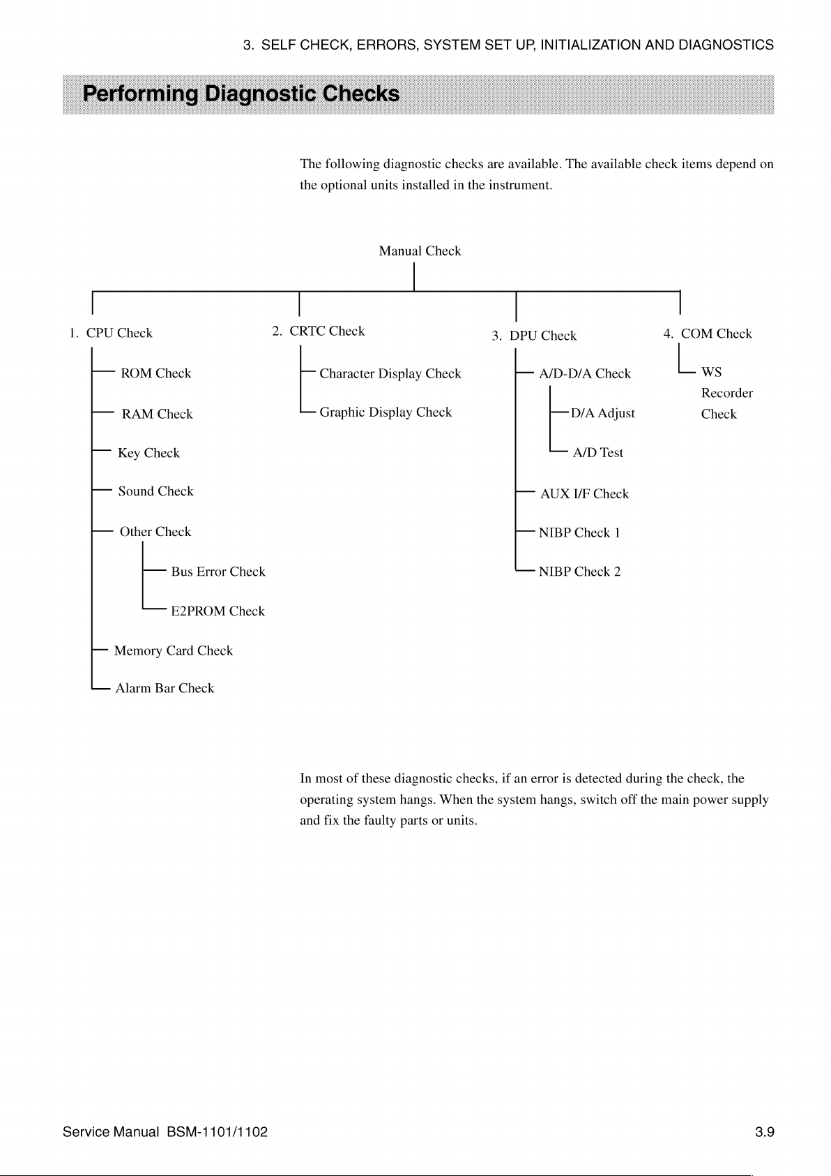
3.
SELF
CHECK,
The
following
the
optional
ERRORS,
diagnostic
units
installed
SYSTEM
checks
in
SET
are
available.
the
instrument.
UP,
INITIALIZATION
The
available
AND
DIAGNOSTICS
check
items
depend
on
1.
CPU
—
ーー
I-
——
—
—
Check
ROM
RAM
Key
Check
Sound
Other
——
Memory
Check
Check
Check
Check
Bus
E2PROM
Card
Error
Check
Check
Check
2.
CRTC
Check
Character
Graphic
Display
Manual
Display
Check
Check
Check
3.
DPU
Check
—
A/D-D/A
—
—
AUX
-—
NIBP
—
NIBP
D/A
A/D
I/F
Check
Check
Check
Adjust
Test
Check
1
2
4.
|
COM
L
Check
WS
Recorder
Check
—
Alarm
Bar
Check
In
most
of
operating
and
fix
the
these
system
faulty
diagnostic
hangs.
When
parts
or
units.
checks,
the
1f
an
system
error
hangs,
1s
detected
switch
during
off
the
the
main
check,
power
the
supply
Service
Manual
BSM-1101/1102
3.9
Page 51

3.
SELF
CHECK,
ERRORS,
SYSTEM
SET
UP,
INITIALIZATION
AND
DIAGNOSTICS
Calling
Screen
Up
the
Check
Menu
|.
From
MENU]
2.
From
screen appears.
|
the
the
i
Diagnostic
key.
The
Check
Menu
2
TEM
Check
Check
284
|
and
Menu
screen,
MANUAL
i.
GPU
2.
СЕТЕ
3.
GPU
É.
COM
ITEM
System
screen
press
CHECK
CHECK
CHECK
si
Setup
appears.
the
[CHECK]
CHECK
СНЕСЕ
CHECE
screen,
#84
|
press
key.
The
RETURN
the
[CHECK
Manual
Check
3.
From
select
4.
Press
5.
To
return
6.
To
return
7.
To
return
[RETURN]
8.
To
exit
monitoring
Procedure
To
return
the
the
the
the
to
to
the
Manual
check
[CHECK]
to
to
to
Return
Check
item.
key
the
Manual
the
Check
the
Diagnostic
key.
Diagnostic
mode,
press
to
the
previous
screen,
screen,
to
go
Check
Menu
Check
the
Previous
press
to
the
screen,
screen,
Check
and
and
System
[MONITOR
Screen
press
the
the
[ITEM
check
press
press
the
System
Setup
MODE]
[RETURN]
screen
the
[RETURN]
[RETURN]
Setup
screen
44]
for
key.
key.
or
[ITEM
that
item.
key.
screen,
and
return
JÉ]
key.
press
key
the
to
to
the
patient
CPU
3.10
Check
Menu
Items
The
following
1.
From
key.
the
The
CPU
Manual
CPU
check
Check
Check
menu
screen,
screen
items
are
select
appears.
explained
CPU
Check
Service
in
the
and
following
press
Manual
pages.
the
[CHECK]
BSM-1101/1102
Page 52

3.
SELF
CHECK,
ERRORS,
SYSTEM
SET
UP,
3,
KEY
CHECK
4.
SOUND
CHECK
INITIALIZATION
AND
DIAGNOSTICS
2.
3.
4.
ROM
From
the
check
Press
check
To
return
Check
the
CPU
Check
screen,
press
the
[ITEM
49]
or
the
item
item.
[CHECK
screen
to
the
START]
appears.
CPU
Check
key
to
Some
screen,
start
the
check
items
press
PASS
selected
run
automatically.
the
[RETURN]
COUNT
0000
[ITEM
check
J]
item.
key.
key
The
to
select
selected
Service
Manual
BSM-1101/1102
This
item
checks
(CRC)
technique.
successfully
If
an
error
message
Procedure
To
return
to
to
the
the
ROMs
on
This
check
completed. A set
Exit
CPU
appears,
the
ROM
Check
the
screen,
the
Digital
assigns a count
of
checks
Digital
Check
takes
board
program
press
board
the
by
the
cyclic-redundancy-check
number
about 1 minute
might
[RETURN]
when
be
faulty.
key.
one
and
set
30
of
checks
seconds.
is
3.11
Page 53

3.
SELF
CHECK,
ERRORS,
SYSTEM
SET
UP,
RAM
Check
This
item
first
wrote
uses
14
patterns
check
takes
INITIALIZATION
checks
the
RAM
on
the
RAM
test
patterns
is
successfully
about 4 minutes
and
AND
BOARD
ESS
BUS
on
the
with
the
test
assigns a count
completed.
and
DIAGNOSTICS
RAM
CHECK
CHECK
—
Digital
10
board
patterns
number
The
comparison
seconds.
484
6
by
comparing
it
later
read
from
when a comparison
of
all
the
the
the
test
patterns
test
RAM.
of
patterns
This
the
14
in
this
it
test
test
The
patient
be
faulty.
Procedure
1.
To
stop
changes
2.
To
return
Key
Check
data
to
Restart,
the
check
to
[CONT].
to
is
destroyed.
Stop,
temporarily,
the
CPU
To
continue
Check
If
an
and
screen,
error
Exit
press
the
message
the
RAM
the
check,
press
appears,
Check
[STOP]
press
the
[RETURN]
key.
the
the
Digital
Program
The
[STOP]
[CONT]
key.
key.
board
key
name
might
3.12
Service
Manual
BSM-1101/1102
Page 54

3.
SELF
CHECK,
This
diagram
instrument
representation
instrument.
CPU
If
has
be
The
check.
item
Check
the
pressed
this
symptom,
faulty.
key
ERRORS,
checks
of
the
key
or
rotating
on
When
screen
key
does
the
key
location
the
screen.
this
appears.
is
not
however,
not
give a key
SYSTEM
operation
on
the
the
multifunction
The
key
is
pressed,
highlighted,
the
SET
UP,
and
multifunction
instrument
only
exception
the
the
membrane
NOTE
click
sound
INITIALIZATION
dials
appears.
dials
Key
key
switch
usually
may
to
Check
be
assembly
when
highlights
this
screen
faulty.
it
AND
of
the
Pressing
case
1s
disappears
If
more
or
Digital
is
pressed
DIAGNOSTICS
instrument.
the
key
the
pressed
the
ETC
and
than
board
in
on
the
key
one
this
A
key
on
the
key
might
the
Procedure
1.
To
check
is
highlighted
2.
To
return
Sound
Check
to
Check
the
key,
to
the
on
the
press
the
CPU
Keys
or
the
key
screen.
Check
to
Exit
and
screen,
the
Key
confirm
press
the
Check
that the
ETC
key.
Program
corresponding
pressed
key
Service
Manual
BSM-1101/1102
This
item
checks
also
can
If
there
is
Procedure
1.
Press
2.
Press
from
be
used
no
sound,
to
the
the
[START]
the 7 types
to
check
the
Check
[ITEM
[START]
to
49]
the
speaker
the
Sound
or
key
[STOP].
of
sounds
alarm
or
Circuit
[ITEM
to
generate
generated
circuit
Digital
J]
key
the
by
and
the
board
might
to
select
selected
the
instrument.
QRS
beep
be
the
sound.
sound.
circuit.
faulty.
The
key
This
name
check
changes
3.13
Page 55

3.
SELF
CHECK,
ERRORS,
SYSTEM
SET
3.
4.
5.
6.
Other
UP,
INITIALIZATION
To
check
the
turn
the
alarm
To
check
the
and
turn
the
To
stop
the
[STOP]
To
return
Check
to
to
alarm
volume
QRS
beep
QRS
beep
sound
check,
[START].
the
CPU
volume
knob
tone
tone
To
continue
Check
AND
DIAGNOSTICS
control
clockwise
volume
volume
press
the
screen,
circuit,
control
knob
[STOP]
the
sound
press
select
any
and
counterclockwise.
circuit,
clockwise
key.
The
check,
the
[RETURN]
alarm
sound
select
any
and
counterclockwise.
key
name
changes
press
the
[START]
key.
QRS
check
beep
key.
and
check
from
This
item
checks
the
contains
ROM
which
If
Procedure
To
check.
the
an
error
return
the
system
The
memory
message
to
Exit
to
the
system
setting
check
area
appears,
the
CPU
program
does
EEPROM
Check
bus
and
data.
This
not
exist
the
Digital
screen,
system
check
checks
and
Check
press
the
board
EEPROM.
has
the
system
detecting
might
Program
the
[RETURN]
same
bus
the
be
The
system
check
by
accessing
bus
error
faulty.
key.
EEPROM
program
an
signal.
as
the
address
at
3.14
Service
Manual
BSM-1101/1102
Page 56

3.
SELF
CHECK,
ERRORS,
SYSTEM
SET
UP,
INITIALIZATION
AND
DIAGNOSTICS
Memory
Card
Balde.
This
item
checks
test
patterns
RAM.
This
comparison
all
the
test
Check
ADGRESS
the
it
first
test
uses
of
the
patterns
ADURESS
memory
wrote
on
14
test
14
test
patterns
in
this
HIS
card
the
patterns
check
CHECK
PASS
inserted
RAM
and
was
takes
-——
DE
COUNT
VO
with
successfully
about
KB
into
the
the
test
assigns a count
11
minutes
0000
instrument
patterns
completed.
it
number
and
15
by
comparing
later
read
when
The
comparison
seconds.
from
a
the
the
of
When
this
the
memory
the
software
If
an
error
board
might
Procedure
1.
To
stop
changes
2.
To
return
3.
To
return
check
displays
card
interface
upgrading
message
be
faulty.
to
Restart,
the
check
to
[CONT].
to
the
to
the
an error,
on
the
procedure.
appears,
CPU
Manual
the
Stop
and
temporarily,
To
continue
Check
Check
replace
PCMCIA
memory
Exit
the
press
the
screen,
screen,
the
board
card,
Memory
the
[STOP]
check,
press
press
memory
is
the
PCMCIA
press
the
[RETURN]
the
card
faulty,
an
Card
Check
key.
The
the
[CONT]
[RETURN]
or
the
error
board,
[STOP]
key.
key.
Digital
occurs
or
the
Program
key
key.
board.
during
Digital
name
If
Service
Manual
BSM-1101/1102
3.15
Page 57

3.
SELF
CHECK,
ERRORS,
SYSTEM
SET
UP,
INITIALIZATION
AND
DIAGNOSTICS
Alarm
This
In
displayed
item
this
Bar
checks
check
on
Check
the
program
the
screen.
operation
the
red,
of
the
yellow,
red,
and
yellow,
green
RETIRE
and
lights
green
are
LEDs
lit
according
in
the
alarm
to
the
bar.
color
CRTC
Check
Menu
Items
If
the
lights
light
up
at
faulty.
Procedure
To
return
The
following
1.
From
key.
The
all,
to
to
the
do
not
the
Exit
the
CRTC
Manual
CRTC
light
according
alarm
bar,
the
Encoder
the
CPU
Alarm
Check
check
Check
Check
Bar
screen,
menu
screen,
screen
Î]
CHARACTER
2.
GRAPHIC DISPLAY
to
the
color
displayed
board,
or
Check
Program
press
the
[RETURN]
items
are
explained
select
CRTC
appears.
DISPLAY
CHECK
CHEEK
the
Check
on
the
Digital
key.
in
the
following
and
screen,
board
press
might
the
or
do
be
pages.
[CHECK]
not
3.16
Service
Manual
BSM-1101/1102
Page 58
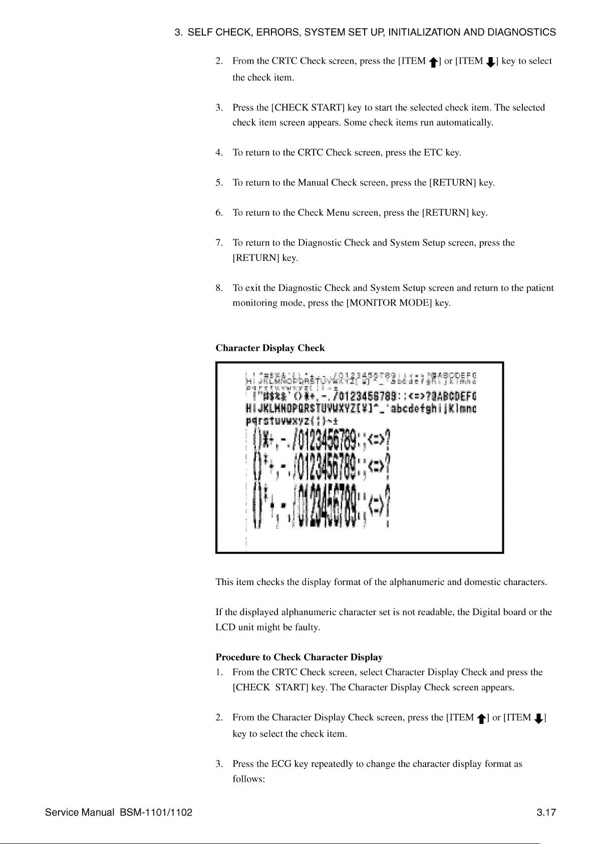
3.
SELF
CHECK,
2.
From
the
3.
Press
check
4.
To
5.
To
6.
To
7.
To
[RETURN]
8.
To
monitoring
ERRORS,
the
check
the
item
return
return
return
return
exit
the
SYSTEM
CRTC
Check
item.
[CHECK
screen
to
the
CRTC
to
the
Manual
to
the
Check
to
the
Diagnostic
key.
Diagnostic
mode,
screen,
START]
appears.
Check
Check
Menu
Check
press
the
SET
UP,
press
key
to
Some
check
screen,
screen,
screen,
Check
and
and
System
[MONITOR
INITIALIZATION
the
[ITEM
start
the
selected
items
run
press
the
ETC
press
the
press
the
[RETURN]
System
Setup
Setup
MODE]
AND
4
or
[ITEM
check
item.
automatically.
key.
[RETURN]
key.
screen,
screen
and
return
key.
DIAGNOSTICS
4!
key
to
The
selected
key.
press
the
to
the
select
patient
Character
This
If
the
LCD
Display
item
checks
the
displayed
unit
alphanumeric
might
be
faulty.
Check
display
format
of
character
the
alphanumeric
set
is
not
and
readable,
domestic
the
Digital
characters.
board
or
the
Service
Manual
BSM-1101/1102
Procedure
1.
From
[CHECK
2.
From
key
to
3.
Press
follows:
to
Check
the
CRTC
START]
the
Character
select
the
ECG
Character
Check
the
check
key
Display
screen,
key.
The
Character
Display
repeatedly
Check
item.
select
to
change
Character
Display
screen,
the
Display
Check
press
the
character
Check
screen
[ITEM
display
and
appears.
4]
or
format
press
[ITEM
as
the
3$]
3.17
Page 59

3.
SELF
CHECK,
ERRORS,
SYSTEM
SET
4.
UP,
INITIALIZATION
Press
the
SpO,
>
normal
|
blinking
highlight
———
blinking
key
AND
highlight
repeatedly
DIAGNOSTICS
to
change
the
character
display
as
follows:
3.18
ВЕ г |
a
a
5.
6.
小
To
To
SRR
Ap
μωρο
return
return
ES
to
to
--
the
Character
the
CRTC
Display
Check
Check
screen,
小
press
screen,
the
[RETURN]
Service
press
Manual
the
[ETC]
key.
key.
BSM-1101/1102
Page 60

3.
SELF
CHECK,
ERRORS,
SYSTEM
SET
UP,
INITIALIZATION
AND
DIAGNOSTICS
Graphic
This
item
waveform
If
the
displayed
LCD
unit
Procedure
1.
Press
display
ECG
key
S
>
Display
checks
displays.
screen
might
be
to
Check
the
ECG,
as
shown
Check
the
linearity
faulty.
the
NIBP,
below.
is
different
Graphic
or
SpO,
of
the
graphic
from
Display
key
that
to
change
display
shown
1
ECG
key
>
the
as
well
below,
four
as
the
four
the
Digital
triangular
triangular
board
or
waveforms
0
the
DPU
Check
Menu
Items
SpO,
key \ /
2.
The
To
return
following
to
DPU
the
CRTC
check
Moving
Check
screen,
menu
items
are
NIBP
mode
press
the
explained
[ETC]
in
key
key.
the
following
pages.
Service
Manual
BSM-1101/1102
1.
From
key.
the
The
Manual
DPU
Check
Check
screen,
screen
select
appears.
DPU
Check
and
press
the
[CHECK]
3.19
Page 61

3.
SELF
CHECK,
ERRORS,
SYSTEM
SET
UP,
INITIALIZATION
AND
Ei
2.
ADR
E
NIEP
DIAGNOSTICS
DPI
CHECK
1/F
CHECK
CHECK
999
From
the
DPU
Check
the
check
Press
the
check
item
To
return
To
return
To
return
To
return
[RETURN]
item.
[CHECK
screen
to
the
to
the
to
the
to
the
key.
screen,
START]
appears.
DPU
Check
Manual
Check
Diagnostic
Check
Menu
press
key
to
Some
screen,
screen,
screen,
Check
the
start
check
press
press
and
[ITEM
the
selected
items
the
press
the
System
4]
or
[ITEM
check
run
automatically.
[ETC]
key.
the
[RETURN]
[RETURN]
Setup
screen,
§]
item.
key.
key.
press
key
The
the
to
select
selected
To
exit
monitoring
A/D-D/A
the
Diagnostic
Check
mode,
À
Check
press
the
AND
TEST
and
System
[MONITOR
Setup
MODE]
screen
key.
and
return
to
the
patient
3.20
Service
Manual
BSM-1101/1102
Page 62

3.
SELF
CHECK,
This
item
pages.
ERRORS,
checks
the
SYSTEM
following
SET
items.
UP,
INITIALIZATION
Each
item
is
explained
AND
DIAGNOSTICS
on
the
following
Procedure
1.
Press
A
Check
2.
Press
3.
Repeat
4.
To
return
D/A
Adjust
to
Select
and
the
[ITEM
screen.
the
[CHECK]
steps 1 and 2 for
to
the
4
DPU
Start
or
key
Check
the
[ITEM
to
start
each
Check
4!
key
the
check
item.
screen,
Item
to
select a check
program
press
the
for
[RETURN]
item
the
selected
key.
from
the
A/D-D/
item.
Service
Manual
BSM-1101/1102
This
check
item
voltmeter
Procedure
1.
Connect
Section
SOOP
2.
From
key.
The
3.
Press
is
selected,
4.
Check
table:
Check
DC
OV
DC
-V
DC
+V
AC
60
checks
or
oscilloscope
to
Carry
the
8,
“Connector
connector.
the
A/D—D/A
D/A
the
[ITEM 會 |
the
the
display
Hz
Out
digital
Adjust
signal
of
ECG
OV
—5.12V
+5.1175V
60
the
D/A
output
is
necessary
the
D/A
voltmeter
Pin
Assignment,’
Check
screen,
screen
appears.
or
ITEM
is
output
the
oscilloscope
Output
+5
mV
+1%
+1%
Hz
sine
wave
voltage
for
this
Adjust
or
Voltage
Check
oscilloscope
select
J]
key
to
the
oscilloscope.
and
level
check.
for
the
D/A
to
select
compare
of
to
the
pin
Adjust
the
the
D/A
converter. A digital
ZB-800P
assignments
and
item.
the
press
When
result
connector.
with
of
the
the
See
the
ZB-
[CHECK]
check
the
following
item
3.21
Page 63
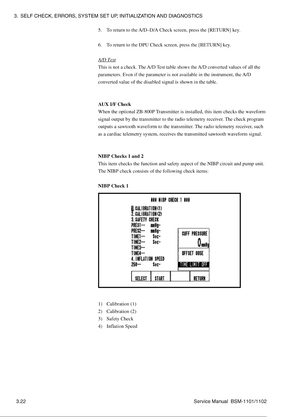
3.
SELF
CHECK,
ERRORS,
SYSTEM
SET
UP,
INITIALIZATION
5.
To
return
to
the
6.
To
return
to
the
A/D
Test
This
1s
not a check.
parameters.
converted
AUX
When
signal
outputs a sawtooth
as a cardiac
NIBP
This
The
NIBP
Even
value
I/F
Check
the
optional
output
by
telemetry
Checks 1 and
item
checks
check
of
the
the
consists
A/D-D/A
DPU
Check
The
A/D
if
the
parameter
the
disabled
ZB-800P
transmitter
waveform
system,
2
function
of
AND
DIAGNOSTICS
Check
screen,
screen,
Test table
signal
Transmitter
to
to
receives
and
the
shows
is
not
is
the
radio
the
transmitter.
the
safety
following
press
press
the
the
available
shown
in
is
installed,
telemetry
The
transmitted
aspect
of
check
items:
the
[RETURN]
[RETURN]
A/D
converted
in
the
instrument,
the
table.
this
item
receiver.
radio
sawtooth
the
NIBP
key.
key.
values
checks
The
check
telemetry
waveform
circuit
of
all
the
A/D
the
waveform
program
receiver,
signal.
and
pump
the
such
unit.
NIBP
Check
Calibration
1)
Calibration
2)
Safety
3)
Inflation
4)
1
a
te
(1)
(2)
Check
Speed
3.22
Service
Manual
BSM-1101/1102
Page 64

3.
SELF
CHECK,
NIBP
Check
ERRORS,
2
SYSTEM
SET
UP,
INITIALIZATION
AND
DIAGNOSTICS
1)
Deflation
2)
Step
3)
Air
Required
e
Hand
e
Manometer
e
Y-shape
can
be
e
700
ml
volume
e
250
ml
volume
e
Two
3.5 m air
Speed
Deflation
Leak
Tools
bulb
pump
hose
connector
connected
dummy
of
dummy
of
cuff
this
container
cuff
this
container
hoses: 1 for
to
the
(A
(A
(Used
hand
solid
must
solid
must
adults
so
that
the
bulb
pump
container
be
700
ml,
container
be
250
ml,
and 1 for
two
and
that
withstands
YS-558R9)
that
withstands
YS-564R2)
neonatals
NIBP
sockets
manometer)
high
high
(dual
on
the
pressure;
pressure;
hose
type)
instrument
the
inner
the
inner
Service
Manual
BSM-1101/1102
Selecting
1.
2.
Make
power
the
3.
Calibration
The
accuracy
measuring
the
and
Press
the
Press
the
sure
on
pressure
To
return
Calibration
of
pressure.
Pressure
Starting
[SELECT]
[START]
there
is
and
entering
of
the
to
the
DPU
(1)
(1)
Check
the
Pressure
The
Sensor | at
NIBP
key
to
key
to
no
pressure
the
pump
Check
program
Sensor
following
different
Check
select
start
NIBP
unit
screen,
1.
The
pressure
the
check
the
check
NOTE
on
the
check.
as 0 mmHg
press
is
used
not
accuracy
table
shows
ranges.
item
for
the
pump
The
check
at
the
[RETURN]
for
calibration
of
the
number.
selected
unit
the
the
acceptable
check
before
program
start
sensor
item.
turning
considers
of
the
key.
but
to
display
changes
accuracy
the
check.
with
the
range
the
of
3.23
Page 65

3.
SELF
CHECK,
ERRORS,
SYSTEM
SET
UP,
INITIALIZATION
AND
DIAGNOSTICS
Pressure
0
to
200
201
to
Checking
1.
Connect
instrument
mmHg
300
the
Range
mmHg
Accuracy
the
manometer
using
the
Acceptable
+3
+4
of
Pressure
and
Y-shape
mmHg
(The
mmHg
Sensor
hand
bulb
hose
connectors
a , Y-shape
Accuracy
displayed
1
pump
to
as
hose
Range
value
the
two
shown
connector
is
always 0 mmHg)
NIBP
sockets
below.
on
the
2.
Press
the
3.
Press
the
4.
Immediately
pump
when
instrument
mmHg).
5.
Compare
pressure
6.
Repeat
7.
Ifthe
accuracy
out
of
the
Calibration
The
Calibration
accuracy
measuring
the
of
pressure.
Pressure
[SELECT]
[START]
start
the
is
the
pressure
reading
key
pumping
pressure
within
on
key
to
to
start
reading
one
of
reading
the
manometer.
select
the
the
hand
displayed
the
two
displayed
steps 4 and 5 for a reading
of
the
acceptable
pressure
accuracy
sensor
range,
(2)
(2)
Check program
the
Pressure
The
Sensor 2 at
Sensor
following
different
is
2.
The
table
pressure
item
number
check.
bulb
pump.
on
the
pressure ranges
on
the
in
the
other
pressure
for
either
replace
used
accuracy
shows
not
for
the
calibration
of
the
the
acceptable
ranges.
1.
Stop
NIBP
NIBP
of
the
Analog
sensor
pumping
Check
(0—200
or
Check
range.
two
pressure ranges
board.
but
changes
accuracy
the
hand
display
201-300
display
to
display
with
range
of
with
the
bulb
the
the
1s
the
of
3,24
Pressure
0-15
mmHg
16-200
201-300
Range
mmHg
mmHg
Acceptable
—2
mmHg
Accuracy
to
+3
always 0 mmHg)
+4
mmHg
+8
mmHg
mmHg
Service
Range
(The
Manual
displayed
BSM-1101/1102
value
is
Page 66

3.
SELF
CHECK,
ERRORS,
SYSTEM
SET
UP,
INITIALIZATION
AND
DIAGNOSTICS
Procedure
1.
Connect
instrument
2.
Press
3.
Press
4.
Immediately
pump
instrument
300
mmHg).
to
the
the
[SELECT]
the
[START]
when
Check
manometer
using
start
the
pressure
is
within
Accuracy
and
the
Y-shape
key
to
key
to
pumping
reading
one
of
of
hand
hose
_
select
start
the
the
Pressure
bulb
connector
N-shape
item
the
check.
hand
bulb
displayed
three
pressure
Sensor
pump
hose
number
pump.
on
2
to
the
two
as
shown
connector
2.
Stop
the
NIBP
ranges
(0-15,
NIBP
below.
pumping
Check
16-200,
sockets
the
hand
display
or
on
bulb
of
201-
the
the
5.
Compare
pressure
6.
Repeat
7.
Ifthe
accuracy
of
the
acceptable
Safety
This
Check
PRESS
PRESS
TIME
TIME
TIME
TIME
The
these
quickly
manometer
guaranteed.
Check
checks
Item
1
2
1
2
3
4
TIME 1 to
items
provide
the
pressure
reading
steps 4 and 5 for a reading
the 6 items
Description
Pressure
Pressure
Time
Time
Interval
Interval
TIME 4 check
require a sensitive
the
and
hand
on
the
of
the
accuracy
monitored
limiter
limiter
limiter
limiter
error
error
right
reading
manometer.
pressure
range,
in
in
in
the
in
the
in
the
in
the
items
pressure
bulb
pump
displayed
sensor
by
the
the
adult
neonatal
adult
neonatal
mechanical
on
in
the
other
for
any
replace
the
adult
neonatal
the
NIBP
mode
mode
mode
mode
mode
NOTE
are
only
at
the
are
used,
the
NIBP
pressure
of
Analog
safety
mode
used
pressure
right
accuracy
Check
the
three
board.
circuit.
Acceptable
315
157.5
161
81to85
>31
>31
in
the
time
display
ranges.
pressure
Range
+15
mmHg
+7.5
mmHg
to165
sec
sec
(5
sec
(20
mmHg)
sec
(10
mmHg)
factory.
generator
interval.
cannot
with
ranges
(15
mmHg)
mmHg)
Because
that
Ifa
be
the
is
can
out
Service
Manual
BSM-1101/1102
3.25
Page 67

3.
SELF
CHECK,
ERRORS,
SYSTEM
SET
UP,
INITIALIZATION
AND
DIAGNOSTICS
Pre-check
Connect
using
Preparation
the
the
Y-shape
manometer
Start
pumping
appears
the
solenoid
next
solenoid
valve.
valve
the
to
hose
these
and
hand
connector
hand
bulb
safety
to
open.
bulb
pump
as
shown
NOTE
pump
check
Inflation
items. A delay
to
the
below.
/Ycshape
as
soon
cannot
NIBP
sockets
connector
as
the
in
continue
on
CHECK
inflation
with
the
instrument
message
causes
an
open
Checking
1.
Connect a 3.5m
2.
Press
3.
Press
4.
Start
5.
Quickly
300
mmHg
ERROR
the
300
message
e
If
the
pressure
the
ERROR
e
Slowly
triggers
less
than
the
PRESS 1 Safety
the
[SELECT]
the
[START]
pumping
increasing
the
increase
pressure
message
to
330
mmHg
also
appears
message
the
safety
15
seconds.
is
air
hose
key
key
to
hand
the
pressure
point,
appears
range.
in
increased
appears.
the
circuit
Check
for
adults
to
select
start
the
bulb
pump
until
slowly
after
the
When
the
cuff
too
pressure
to
display
Item
to
the
item
number
check.
as
soon
the
manometer
increase
inflated
the
OK
pressure
NOTES
quickly
after
the
instrument.
3.
as
the
CHECK
the
pressure
pressure
message
window.
to a value
the
300
mmHg
OK
or
message
reads
300
mmHg.
further.
reaches a certain
appears,
above
ERROR
The
the
SAFETY
330
pressure
message
appears.
From
the
OK
or
value
in
ON
mmHg,
point
in
3.26
When
the
the
next
OK
or
safety
ERROR
check
message
item,
TIME
appears,
1.
This
waiting
the
WAIT
Service
message
period
Manual
is
about
BSM-1101/1102
also
33
appears
seconds.
in
Page 68

3.
SELF
CHECK,
6.
Open
then
must
ERRORS,
the
valve
close
the
be
done
SYSTEM
in
the
valve
within
hand
to
prepare
33
seconds.
SET
bulb
pump
the
UP,
INITIALIZATION
until
the
hand
bulb
pump
manometer
for
the
AND
DIAGNOSTICS
reads 0 mmHg,
next
check.
This
Checking
1.
2.
3.
4.
5.
e
If
the
e
Slowly
triggers
less
the
PRESS 2 Safety
Connect a 3.5 m air
Press
the
[SELECT]
Press
the
[START]
Start
pumping
the
WAIT
message.
Quickly
150
ERROR
the
message
the
increase
mmHg
message
150
to165
also
pressure
ERROR
increasing
the
than
7.5
key
the
hand
the
pressure
appears
mmHg
appears
is
increased
message
the
safety
seconds.
hose
for
key
to
to
start
bulb
pressure
point,
after
range.
in
the
appears.
pressure
circuit
Check
neonatals
select
the
pump
until
slowly
the
When
cuff
pressure
NOTES
too
to
display
Item
to
the
item
number
check.
as
soon
the
manometer
increase
inflated
the
OK
window.
quickly
after
the
the
instrument.
3.
as
the
CHECK
reads
the
pressure
pressure
reaches a certain
message
to a value
150
mmHg
OK
or
message
150
further.
appears,
above
pressure
ERROR
mmHg.
The
the
SAFETY
165
message
replaces
From
the
OK
or
value
in
ON
mmHg,
point
in
When
the
next
6.
Open
then
close
must
Inflation
This
checks
the
cuff
pressure
Procedure
1.
Connect
hose
the
safety
the
be
done
Speed
the
to
as
shown
OK
or
check
valve
the
valve
within
inflation
must
Check
the
700
below.
ERROR
in
the
the
ml
be
message
item,
TIME
hand
bulb
to
prepare
33
seconds.
speed
of
able
to
Inflation
dummy
cuff
pump
the
the
reach
Speed
to
appears,
2.
This
waiting
until
hand
bulb
pressure
250
mmHg
the
NIBP
the
WAIT
the
manometer
pump
pumps.
in
socket
message
period
is
about
reads 0 mmHg,
for
the
next
The
specifications
less
than 7 seconds.
with
the
also
appears
33
seconds.
check.
This
state
3.5 m dual
in
that
air
Service
Manual
BSM-1101/1102
3.27
Page 69

3.
SELF
CHECK,
ERRORS,
SYSTEM
SET
UP,
INITIALIZATION
AND
DIAGNOSTICS
700
2.
Press
the
3.
Press
the
If
the
inflation
Step
Deflation
This
checks
Valve 1 opens
pressure,
the
Valve 1 opens
ml
dummy
[SELECT]
[START]
speed
step
for
60
cuff
key
to
key
to
is
less
than 7 seconds,
deflation
ms
and
Valve 2 opens
for
40
select
start
of
the
ms
and
check
item
the
check.
an
cuff
at
given
for
Valve 2 opens
number
OK
message
pressures.
80
ms
at
for
4.
20
70
At
mmHg.
ms
appears.
the
LOW
At
at
250
pressure,
the
HIGH
mmHg.
Procedure
1.
Connect
shown
2.
Press
to
Check
the
the
250
ml
below.
250
ml
dummy
the
[SELECT]
Step
dummy
cuff
key
Deflation
cuff
to
select
to
the
check
Speed
NIBP
item
socket
number
with
5.
the
3.5 m air
hose
as
3.28
3.
Press
Depending
the
on
[START]
the
result
key
of
to
the
start
the
check,
check.
an
OK
or
ERROR
Service
message
Manual
appears.
BSM-1101/1102
Page 70

3.
SELF
CHECK,
Air
Leak
This
checks
check,
the
compares
seconds
pressure
ERROR
ERRORS,
for
air
air
pressure
the
pressure
after
the
readings
message
SYSTEM
leakage
of
readings
pressure
differ
by
appears.
in
the
the
dummy
of
the
less
than 5 mmHg,
SET
UP,
air
compartment
cuff
of
the
dummy
dummy
INITIALIZATION
of
the
is
increased
cuff
cuff
has
an
to
taken
reached
OK
message
NIBP
250
at
30
250
AND
DIAGNOSTICS
module.
mmHg.
seconds
mmHg.
appears.
It
If
In
then
and
the
If
not,
this
90
an
Procedure
1.
Connect
shown
below.
to
the
Check
700
ml
dummy
2.
Press
the
[SELECT]
700
the
ml
cuff
Air
dummy
key
to
Leak
cuff
select
to
the
check
NIBP
item
socket
number
with
7.
the
3.5 m air
hose
as
COM
Check
Menu
Items
3.
Press
Depending
The
following
1.
From
Check
2.
From
key.
The
the
[START]
on
the
Check
screen
the
Manual
COM
the
result
COM
appears.
key
Check
Menu
Check
Check
to
of
the
Menu
screen,
screen
start
the
check,
items
press
screen,
appears.
check.
an
OK
are
the
select
or
ERROR
explained
[MANUAL
COM
Check
message
on
the
CHECK]
and
appears.
following
key.
press
the
pages.
The
Manual
[CHECK]
Service
Manual
BSM-1101/1102
3.29
Page 71

3.
SELF
CHECK,
ERRORS,
SYSTEM
SET
UP,
INITIALIZATION
AND
DIAGNOSTICS
3.
Press
the
automatically.
4.
To
return
WS
Recorder
[CHECK
to
Check
the
COM
114
START]
Check
№5
RECORDER
key
screen,
to
start
press
CHECA
the
WS
the
[RETURN]
FRR
Recorder
check,
key.
which
i
runs
3.30
This
item
checks
the
board
by
If
an
error
Procedure
1.
Press
highlighted
the
test
communication
printing a test
message
to
the
printout.
appears,
Start,
Stop,
[START/STOP]
when
the
printout.
the
and
[START/STOP]
Digital
Exit
key
to
between
board
the
WS
start
the
or
Recorder
the
check.
key
is
recorder
the
recorder
The
pressed.
Service
unit
Check
start
The
Manual
and
the
unit
might
Program
or
stop
recorder
BSM-1101/1102
Digital
be
key
name
unit
faulty.
is
prints
Page 72

3.
SELF
CHECK,
ERRORS,
RECORDER
SYSTEM
COMMUNICATION
SET
UP,
INITIALIZATION
TEST
!’#$%&'()*+,-./0123456789
AND
DIAGNOSTICS
2.
3.
To
To
stop
the
return
check,
to
the
圖
COM
press
Check
the
[START/STOP]
screen,
press
NIHON
key
the
[RETURN]
KOHDEN
again.
key.
Service
Manual
BSM-1101/1102
3.31
Page 73

Section
4
Board/Unit
Descriptions
Overall
Digital
Analog
PCMCIA
[СО
SDO。
Function
Board...
Boot
Recording
Display
PowerControlBlock........................................
Standby
System
Power
Battery
BatteyChargingandDischarging.............»................
Power
Sound
CIO
ZB
Interface
Boargd
Analog
Input
Power
AC/DC
DC/DC
AC
Line
ECG
NIBP
Board
Memory
니다
. 2
SysStem
SpO,
SpO。
Block
and
Memory
Block
Block
Mode
On
Control
SOUrce
Charge
Input
Load
Synthesizer
eee
.4
Processing
Control
CilCUll
System
이이 이 이
Processing
Processind
Block..."
Supply
Converter
Converter
Frequency
.Nt
Card
이 피 미 마 미 파 마 마 마 마 마 파 마 파 다 파 마 파 아 파 아 파 이 아 아 파 아 아 아 아 아 아 아 아 어 다 아 아 어 아 어 아 어 아 어 나 어 나 어 니 어 니 아 니니
iii
Diagram
Block
.............
SUpplY
Level
Check...
Unit
.4
Interface
Circuit
Circult
Vies
.4
.....................
Display
een
Block
"sise.
Block
Detector
BIOCK
(BSM-1101)
(BSM-1102)
"Vs
4
...040000
2.0000
нии
ини
iii
000000
000000000
eee
нии
nn
eere
KK
KKK
KKK
PKR
KKK
PAKA
K
KK
KK K KK
PPK O KKK
KKK
KKK
eee
eee
eee
neee
eneeeeasneaaananana
emen
een
eee
KKK AKA PKR ARR
KKK
KaK
PARK
nene
KKK KKK
ELL
KRKA
KRKA
ep
es
OKR
нение
nn
εκων
eee
EEETE
o
enao
KKK
En
4.1
4.2
4.2
4.3
4.4
4.4
4.5
4.5
4.5
4.5
4.5
4.5
4.6
4.6
4.6
4.7
4.7
4.7
4.8
4.8
4.8
4.9
4.9
4.10
4.11
4.11
4.11
4,12
4.12
4.13
Service
Manual
BSM-1101/1102
4C.1
Page 74

pieog
ーーー
ーー
VIONOd
NVHAN
42019
|
[2
|
pe
YIOMISN
Le
pied
AJouueW
ρα
Thy
A[NPOIA]
1ΘΡΙΟΟΘΗ
18P1098H
Ρ1ΙΟΟΘΗ
ΙΘΡΙΟΟΘΗ
ww
<,
01609
PICO"
|
|g
pieog
|-<
JO1BOIDU|
UDJIMS
JeNmod
』9AOd-
ゴ
>
ーー
Tomo,
oms
OJIM
<p»
PJPO
,
9DO9U
ゴ
<
19111416461|
4008-97
개
ея
шлем
4.
BOARD/UNIT
sgouy
1UBiMoeg/ewun|oA
sleldq
uollounJnlnW
10460
433
DESCRIPTIONS
01609
|
티
010
ΘΙΠΡΟΙΛ
uolldO
NOH/NVH
wajsÁs
p1eog
>
|
ndo
|
v
>
903
TI
トー
|
Syno119
ーー
pJeog
Jeog
Bojeu
DOIBUV
Burneol-
ニー
ニー
-
」
|
903
|
|
593
—
|
|
>
sng
UIEN
|
|
|
|
>
“od
025
(I
|
005
006
|
|
ons
ペーー
ト
ーー
?Od
>
|
u
S|
A
\
|
«
OISV
αν
«
ddIN
dain
|
Jebpeg
ご
>
Y
y
ΘΙΠΡΟΙΝ
|
JIV
|
Il
|
04140
19M0g
9
Le
Aouenbel
раза
eum
1
|
[77
seAjeA/dund
19944
99143
ITEH
IIB
JSZISOUJUÁS
시
>
90-90
01608
AJalleg9
ーー
90/0V
SIO
eum
9V
Service
Manual
BSM-1101/1102
4.1
Page 75
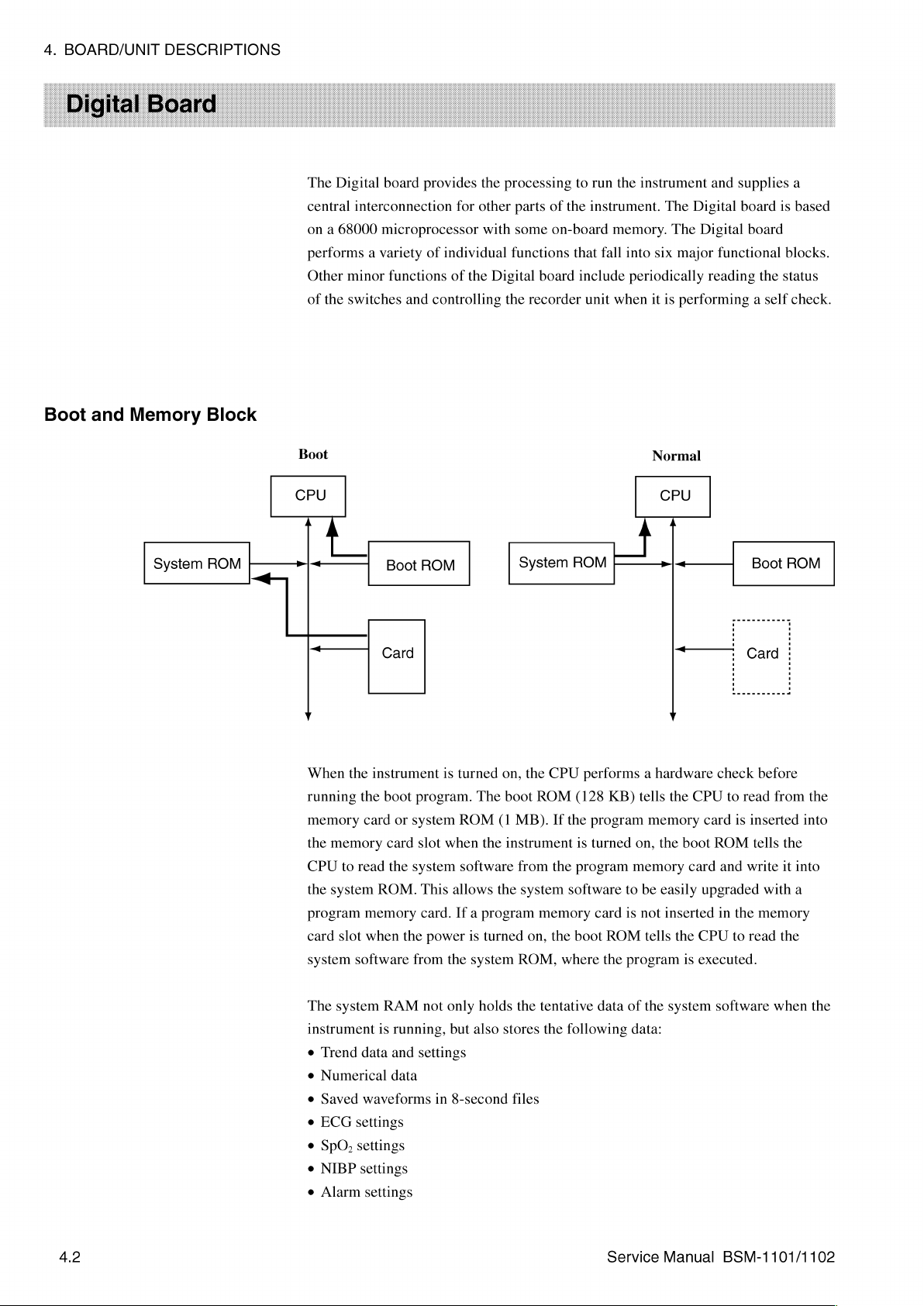
4.
BOARD/UNIT
DESCRIPTIONS
The
Digital
central
on a 68000
board
interconnection
microprocessor
performs a variety
Other
minor
functions
of
the
switches
and
provides
for
the
other
with
of
individual
of
the
controlling
processing
parts
some
functions
Digital
board
the
recorder
to
run
of
the
instrument.
on-board
that
include
unit
the
instrument
memory.
fall
into
periodically
when
it
and
supplies
The
Digital
board
The
Digital
six
major
functional
reading
is
performing a self
board
the
a
is
based
blocks.
status
check.
Boot
and
Memory
System
Block
ROM
Boot
CPU
|
A
| |
<
v
When
running
memory
the
memory
CPU
to
the
system
program
card
slot
system
Boot
Сага
the
instrument
the
boot
card
card
read
the
ROM.
memory
when
software
ROM
program.
or
system
slot
system
This
card.
the
from
is
turned
ROM
when
software
allows
If a program
power
the
The
(1
the
the
is
turned
system
System
on,
the
CPU
boot
ROM
MB).
If
instrument
from
the
system
memory
on,
the
ROM,
ROM
performs a hardware
(128
the
is
program
software
boot
where
program
turned
card
the
KB)
to
is
ROM
program
Normal
CPU
A
— | -<
+—
Y
tells
the
memory
on,
the
boot
memory
be
easily
not
inserted
tells
the
is
check
CPU
to
card
is
ROM
card
and
upgraded
in
the
CPU
to
executed.
Boot
ROM
Card
before
read
from
inserted
tells
the
write
it
with
memory
read
the
|
the
into
into
a
4.2
The
system
instrument
e
Trend
data
e
Numerical
e
Saved
waveforms
e
ECG
settings
e
SpO,
settings
e
NIBP
settings
e
Alarm
settings
RAM
is
running,
and
data
not
only
but
settings
in
8-second
holds
also
the
stores
files
tentative
the
following
data
Service
of
the
data:
system
Manual
software
BSM-1101/1102
when
the
Page 76

A
capacitor
after
the
instrument
after
30
minutes
The
system
Therefore,
clear
this
RAM
is
used
and
this
of
alarm
data
data
to
back
is
turned
power
master
is
not
is
to
up
the
above
off.
System
off
due
to
settings
lost
when
initialize
the
4.
BOARD/UNIT
data
in
the
software,
unreliability
data
the
instrument
system.
are
of
stored
DESCRIPTIONS
RAM
for
approximately 1 hour
however,
data.
in a non-volatile
is
turned
erases
off.
The
the
static
only
stored
RAM.
way
data
to
Recording
Block
Digital
Host
CPU
This
controlled
board.
can
also
Board
block
Similar
be
|
|
|
|
|
is
controlled
by
the
system
to
the
upgraded
Recorder
-
by a local
ROM
through a program
Board
Local
>
CPU
-|
Recorder
This
CPU
Recorder
in
this
ROM
CPU
the
Digital
Digital
R
RAM | |
with
its
board
board,
card.
| |
ROM
own
ROM
and
via
ASIC
the
program
RAM.
on
the
stored
АЗС
CPU
on
in
the
is
Service
Manual
BSM-1101/1102
Although
processing
the
on
such
command
of
Recorder
system
the
Recorder
as
the
thermal
the
the
board.
recording
is
performed
CPU
on
board
waveform
signals
head
the
to
data,
the
in
via
the
Digital
block
is
by
ASIC
board
its
ASIC.
trendgraph
recorder
recorder
controlled
on
the
Recorder
outputs
The
local
data,
unit
for
the
unit
is
also
by
the
host
the
record
CPU
or
list
recording
controlled
CPU,
board.
In
command
processes
data,
and
operation.
by
most
of
the
recording
to
the
recording
outputs
The
the
local
the
CPU
process,
the
local
data,
thermal
head
temperature
CPU
on
CPU
the
4.3
Page 77
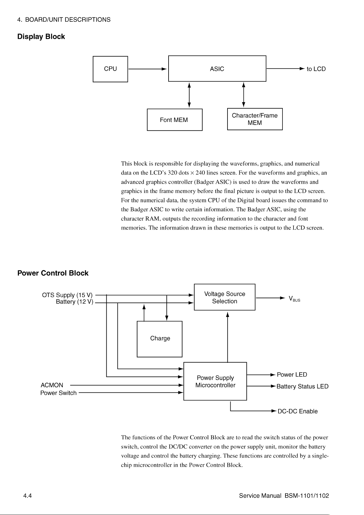
4.
BOARD/UNIT
DESCRIPTIONS
Display
Block
CPU
This
block
data
on
the
advanced
graphics
For
the
character
memories.
in
the
numerical
Badger
Font
is
responsible
LCD’s
graphics
the
frame
ASIC
RAM,
outputs
The
information
у
MEM
for
320
dots x 240
controller
memory
data,
the
to
write
certain
the
ASIC
displaying
lines
(Badger
before
system
CPU
information.
recording
drawn
in
Character/Frame
the
waveforms,
screen.
ASIC)
is
the
final
picture
of
the
Digital
The
information
these
memories
у
For
used
MEM
graphics,
the
waveforms
to
draw
is
output
board
Badger
to
the
is
output
and
the
waveforms
to
the
issues
ASIC,
using
character
to
the
>
numerical
and
graphics,
LCD
the
command
the
and
font
LCD
to
LCD
an
and
screen.
to
screen.
Power
Control
OTS
Supply
Battery
ACMON
Power
Switch
Block
(15
(12
V)
V)
The
switch,
voltage
chip
Charge
of
the
the
control
DC/DC
functions
control
and
microcontroller
Power
the
battery
in
Voltage
Yy
VY
Power
Microcontroller
VY
Control
converter
charging.
the
Power
Control
Source
Selection
A
Supply
Block
are
on
the
These
Block.
to
read
power
functions
—————=>
Battery
the
switch
supply
are
Power
>
DC-DC
status
unit,
monitor
controlled
Veus
LED
Status
Enable
of
the
the
by a single-
LED
power
battery
4.4
Service
Manual
BSM-1101/1102
Page 78
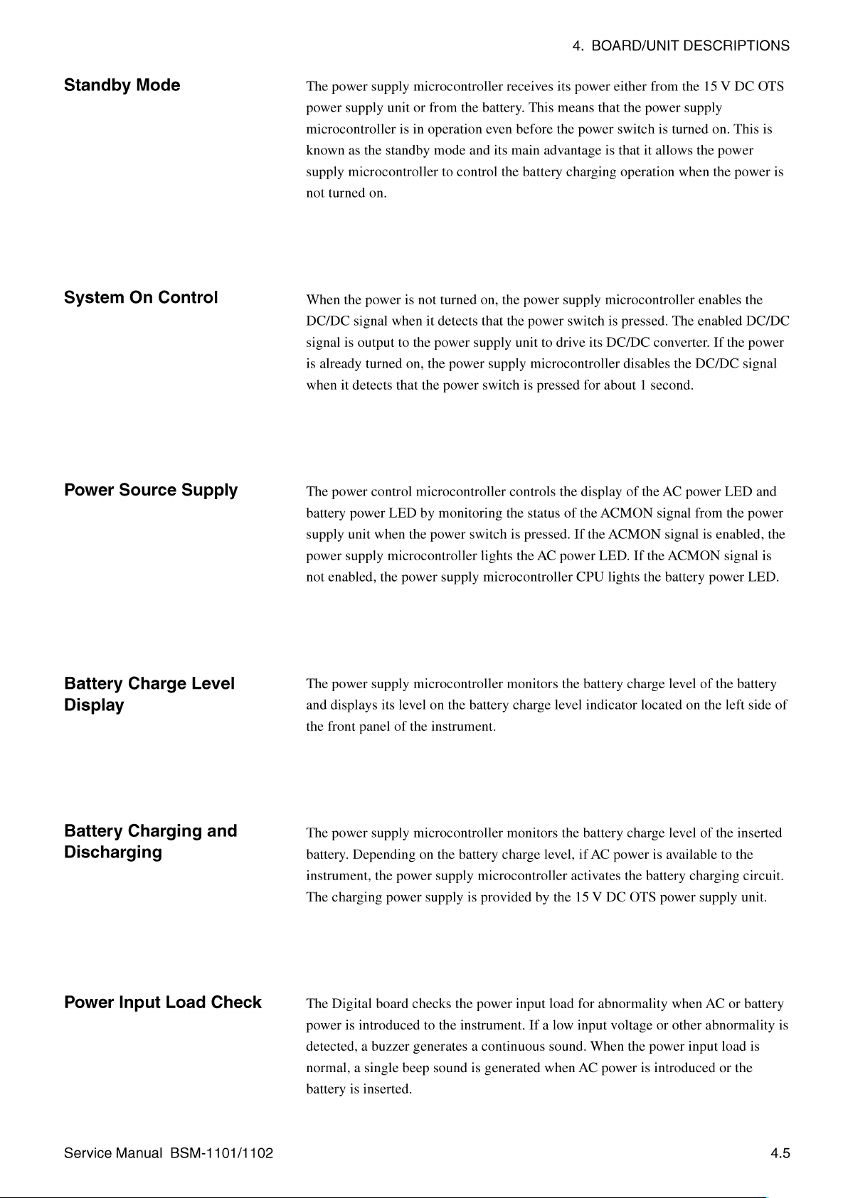
4.
BOARD/UNIT
DESCRIPTIONS
Standby
System
Power
Source
Mode
On
Control
Supply
The
power
supply
power
supply
microcontroller
known
supply
not
turned
When
the
DC/DC
signal
is
is
already
when
it
The
power
battery
supply
power
supply
not
enabled,
unit
as
the
standby
microcontroller
on.
power
signal
when
output
to
turned
detects
power
unit
that
control
LED
when
microcontroller
the
microcontroller
or
from
the
is
in
operation
mode
and
to
control
is
not
turned
it
detects
the
power
supply
on,
the
power
the
power
microcontroller
by
monitoring
the
power
switch
power
supply
receives
battery.
even
its
main
the
on,
the
that
the
supply
switch
controls
the
is
lights
microcontroller
its
This
means
before
the
advantage
battery
power
unit
is
the
charging
supply
power
switch
to
drive
microcontroller
pressed
the
status
of
pressed.
AC
power
power
either
that
the
power
switch
is
that
operation
microcontroller
is
pressed.
its
DC/DC
disables
for
about 1 second.
display
the
If
CPU
ACMON
the
LED.
of
ACMON
If
lights
from
the
power
supply
is
turned
it
allows
when
The
converter.
the
the
AC
power
signal
signal
the
ACMON
the
battery
15 V DC
on.
the
power
the
enables
enabled
If
the
DC/DC
LED
from
the
is
enabled,
signal
power
OTS
This
power
the
DC/DC
power
signal
and
power
LED.
1s
is
the
is
Battery
Charge
Display
Battery
Charging
Discharging
Power
Input
Level
Load
and
Check
The
power
supply
and
displays
the
front
power
The
battery.
instrument,
The
charging
The
Digital
power
detected, a buzzer
normal, a single
battery
its
panel
supply
Depending
the
power
board
is
introduced
is
inserted.
level
of
power
beep
microcontroller
on
the
the
instrument.
microcontroller
on
the
battery
supply
supply
checks
the
to
the
instrument.
generates a continuous
sound
monitors
battery
is
is
charge
monitors
charge
microcontroller
provided
power
input
If a low
generated
level
level,
by
the
load
sound.
when
the
battery
indicator
the
battery
if
AC
activates
15 V DC
for
abnormality
input
When
AC
power
charge
located
charge
power
the
battery
OTS
voltage
the
power
is
level
of
on
the
level
of
is
available
charging
power
supply
when
AC
or
other
abnormality
input
introduced
the
battery
left
the
inserted
to
the
or
load
or
the
side
of
circuit.
unit.
battery
is
is
Service
Manual
BSM-1101/1102
4.5
Page 79

4.
BOARD/UNIT
DESCRIPTIONS
Sound
Key
Panel
Synthesizer
(3.072
Block
CLK
MHz)
一
_m
Synthesizer
FM
Sound
data
This
block
is
based
on
an
generates
amplified
these
The
the
key,
RECORDER
the
QRS
and
output
sounds
Digital
instrument.
NIBP
is
board
START/STOP
START/STOP
sync
to
the
controlled
monitors
The
membrane
FM
and
speaker
by
the
key,
key,
Sound
synthesizer
alarm
sound
connected
the
CPU.
status
switches
HOME
and
signal
that,
signals.
of
the
membrane
are:
SUSPEND
key,
ETC
RECORDING
Do
イン
under
These
to
the
key,
Sound
the
control
sound
Digital
switches
ALARM
NIBP
key,
PATTERN
of
signals
board.
on
key,
SpO,
SELECT
signal
the
CPU,
are
The
volume
the
key
REVIEW
key,
key.
>
then
panel
ECG
of
of
key,
ZB
Interface
This
interface
for
telemetry
patient
is
available
capability.
information
for
the
With
this
to a telemetry
instrument
transmitter,
monitor
to
such
connect
the
as a cardiac
to a ZB-800P
instrument
can
transmit
telemetry
Transmitter
certain
system.
4.6
Service
Manual
BSM-1101/1102
Page 80

4.
BOARD/UNIT
DESCRIPTIONS
Analog
Processing
Block
ECG-DISP - ㅡ
ECG-COUNT
SpO,
NBP
Return-ECG
ECG-ZB
The
analog
multiplexer,
signals
e
Patient
SpO,
e
Sound
e
Brightness
~
—
—%|
——
——~
—
processing
and
into
corresponding
measured
volume
volume
12-bit
AD
b>...
P
MUX
De-MUX
block
demultiplexer.
parameters
-中 一 一
consists
The
digital
such
———
+t
A/D
signals:
as
Volume
Volume
Brightness
of
an
A/D
converter
ECG,
alarm
ECG
D/A
converter, a D/A
converts
non-invasive
—————_
the
blood
converter,
following
pressures,
>
CPU
СРО
analog
and
Input
Service
Control
Manual
Block
BSM-1101/1102
Floating
Circuit
Precision
_
Optocoupler
γ
Digital
Optocouplers
Analog
(2)
Processing
circuit
Lead
Command/Control
Lead
Status
—
A/D
A
Hum
ASIC
«CPU
4./
Page 81

4.
BOARD/UNIT
DESCRIPTIONS
This
block
switching
This
block
the
ECG
leads
selection
signal.
These
Apart
from
serial
communication
circuit
and
controls
on
or
also
board
are
the
SpO,
the
non-floating
off
the
hum
generates
and
SpO,
signal,
the 3 leads
output
above
control
between
circuit.
filter
another
board.
to
or
circuits
control
type
This
measuring
input
from
signals,
the
floating
signal.
of
control
second
the
this
block
and
of
the
ECG
signals
type
of
control
mode
signal,
floating
circuit
also
generates
non-floating
board
for
the
signals
and
via
circuits
and
SpO,
floating
include
the
lead
digital
the
timing
of
board
by
circuit
of
the
status
optocoupler.
signal
for
the
ECG
Power
Supply
Unit
AC
The
AC
filter
is
is
input
power.
power
line
TP
power
located
into
the
The
Power
supplies
AC
to
pcisv
DC-DC
switch
is
on
at
the
rear
panel
OTS
power
Control
required
by
15 V DC
the
front
of
supply
circuit
then
the
instrument.
of
the
the
instrument.
unit,
which
converts
Veus
DC
instrument.
The
converts
the
15 V DC
to
DC
A
The
AC
output
the
AC
+
[+53
—p
inlet
of
these
power
power
+24
V
+8
V
pp
-8
V
»
ACCLK
with
fuse
components
to
15 V DC
to
the
various
V
line
AC/DC
DC/DC
4.8
Converter
Converter
The
power
into
15 V DC
Power
The
DC/DC
and
—8 V when
supply
Control
converter
unit
power.
Block
it
receives
uses
At
the
that
AC
changes
the
an
AC/DC
same
power
the
command
converter
time,
supply
15 V DC
the
ACMON
signal
to
is
available
power
from
Service
convert
signal
to
into
+3.3
the
Power
Manual
the
AC
is
enabled
the
instrument.
V,
+5
Control
power
source
to
inform
V,
+8
V,
—5
V,
Block.
BSM-1101/1102
the
Page 82

AC
Line
Detector
ECG
Circuit
Freq
uency
The
AC
AC
line
line
frequency
frequency
to
the
detector
SpO,
circuit
4.
outputs a pulse
on
the
Analog
BOARD/UNIT
signal
that
board.
DESCRIPTIONS
is
synchronized
with
the
—
—
Analog
optocoupler
V
IN
|
||
AMP
“|
ECG
x500
|
Input
Connectori
+
Ť
--
위
|
.
Digital
optocoupler
)
Y
+
+
K
х
|
150Hz
-一
—
о
>
|
FLT-TX
-
FLT-RX
一
—
-ECG
-
ECG
ECG
HUM
ZB
CONT
DISP
The
input
circuits
to
protect
input
input
transformers.
For
ECG
analog
hum
status,
input
CAL
non-isolated
The
Therefore,
Digital
the
signals
circuit
ECG
signal
circuit
optocoupler.
filtering.
connector
circuit
control
output
connector
the
board
in
input
amplifiers
from
the
is
isolated
processing,
amplify
The
The
FLT_RX
connection
performs
when
it
side
through
finally
via
the
the
ECG
patient
from
the
the
the
signal
ECG
signal
and
the
lead
receives
another
to
the
Analog
processed
Analog
module
board
are
from
defibrillation
lead
electrodes.
other
circuits by
operational
before
it
signal
from
from
excessive
selection,
the
FLT_TX
digital
board
and
A/D
through
eguipped
goes
the
the
time
optocoupler.
is
converted
with
and
For
further
photocouplers
amplifiers
to
the
analog
digital
optocouplers
polarization
constant
lead
select
located
this
output
high
impedance
high-frequency
patient
in
the
input
non-isolated
optocoupler
voltage
switching,
command
on
this
ECG
information.
printed
signal
is
connector.
components
interference
protection,
and
isolation
circuits
circuits
is
carries
INST
signal
output
of
through
processed
the
control
from
circuit
board.
to
this
the
an
for
lead
The
and
the
the
Service
Manual
BSM-1101/1102
4.9
Page 83

4.
BOARD/UNIT
DESCRIPTIONS
NIBP
System
The
NIBP
system
and
valve
components.
solenoid
the
pressure
e
e
e
e
e
e
e
e
e
e
Under
and
safety
valves.
change
for
Inflates
the
Deflates
Monitors
Prevents
Monitors
Monitors
Monitors
Zero
calibrates
Processes
through
Informs
the
the
normal
valves
circuit
the
the
in
immediately
are:
consists
The
in
blood
any
abnormality.
cuff
during
cuff
during
the
change
cuff
the
inflation
the
total
the
power
the
the
NIBP
12-bit
system
conditions,
the
NIBP
takes
control
stopping
of
These
NIBP
system
pressure
NIBP
NIBP
in
the
from
over-inflating
and
measuring
supply
cuff
pressure
signal
A/D
CPU
on
the
system.
of
the
pump
the
NIBP
circuitry
components
is
also
in
the
cuff
The
NIBP
measurement
measurement
cuff
pressure
deflation
time
time
In
the
NIBP
in
both
and
outputs
the
Digital
system
the
CPU
Under abnormal
operations
and
opening
on
the
contain | air
equipped
and
the
system
with 2 sensors, | for
other
performs
by
controlling
by
controlling
through a sensor
of
cuff
circuit
measurement
the
processed
board
if
it
detects
on
the
Digital
conditions,
of
the
pump
the
valves.
Analog
compressor
for
monitoring
the
and
NIBP
any
board
and
The
board
following
the
pump
the
valves
on
the
NIBP
safety
circuits
signal
to
abnormality
controls
however,
valves
abnormal
and
the
pump
and
measuring
the
cuff
functions:
circuitry
the
CPU
the
the
NIBP
by
conditions
pump
2
pump
e
When a power
e
When
the
e
When
the
e
When
the
e
When
the
down
pressure
inflation
of
time
deflation
interval
between
situation
the
inflated
is
over
time
is
over
is
detected
cuff
is
its
preset
its
preset
measurements
over
its
limits
limits
is
different
preset
from
limits
its
preset
value
4.10
Service
Manual
BSM-1101/1102
Page 84

4.
BOARD/UNIT
DESCRIPTIONS
Memory
Block
Card
Interface
The
memory
switchability
switch
instrument
data
memory
The
LCD
diagonal
16 M colors,
and
numerical
from
unit
size
card
among
attribute
can
this
interface
its
is
seven
memory
read
from a program
card.
has a resolution
of
5.5
inches
(139.7
instrument
data
display.
only
based
memory
mode
of
320
mm).
allows
on
the
JEIDA
banks
to
common
memory
dots x 240
Although
4096
Version
of
512
KB
memory
card
and
lines
the
selectable
4.0
protocol.
each
lets
the
mode.
This
also
read
from,
and a visible
LCD
unit
can
colors
for
Its
interface
means
or
write
display
display
the
waveforms
the
up
to,
to
a
The
polarization
high
pressure. A resin
handling
surface
and
The
life
is
backlight
clean
LCD
span
the
of
of
the
the
is
of
number
is
environment
hours
of
continuous
filter
on
protects
the
LCD
screen.
LCD
must
LCD
screen
illuminated
the
backlight
of
hours
for
continuously
of
the
instrument,
use.
the
surface
The
be
cleaned
quickly.
from
behind
is
10,000
the
on
at
of
this
polarization
resin
is
with
(backlight)
hours
intensity
maximum
the
LCD
the
LCD
screen
filter
sensitive
alcohol,
to
use
by 2 cold
(approximately
to
reach
50%
brightness.
may
need
to
is
sensitive
from
shock
strong
alcohol,
diluted
alcohol
cathode
14
months).
of
its
original
Depending
be
replaced
to
shock
and
rough
so
if
the
on a cloth
electrodes.
The
value
when
on
the
operating
after
10,000
and
life
The
span
the
Service
Manual
BSM-1101/1102
4.11
Page 85

4.
BOARD/UNIT
DESCRIPTIONS
The
following
are
used
for
BSM-1101
circuits
process
and
BSM-1102.
the
SpO,
signals.
Different
SpO,
processing
circuits
SpO,
Processing
(BSM-1101)
Circuit
Input
Connector
The
input
circuits
optotocouplers
The
processed
barrier
SPO,
through
to
the
|
in
and
signals
analog
Digital
SpO2
Απρ
the
SpO,
isolation
board
transformers
from
the
optocouplers.
via
|
system
the
Analog
SpO,
Analog
are
isolated
for
patient
processing
The
SpO,
board.
optocoupler
i
BY
Digital
optocoupler
À
V
Y
EK
from
protection.
circuit
circuit
SpO>
Amp2
the
non-floating
pass
across
then
outputs
|"
circuits
the
isolation
the
processed
SPOW
FLT-TX
-
FLTAX
by
4.12
The
SpO,
processing
probe
ID
detection
The
LED
control
LEDs
in
the
synchronized
frequency
the
The
sensor
This
from
photodiode
signal
AC
Line
function
of
the
input
the
sensor.
detected
detection
processing
is
circuit,
circuit
probe.
The
with
the
circuit.
Frequency
of
the
probe
SpO,
probe.
In
the
amplified
with
no
circuit
and
also
source
AC
line
This
Setting
ID
circuit
input
and
LED
consists
controls
detection
later
processing
filtered
light
of
input
processing
the
timing
frequency
source
system
uses
by a low-pass
is
used
three
timing
signal
in
the
timing
setup
circuit
this
ID
circuit,
as
the
smaller
used
screen.
circuits:
circuit.
signal
by
this
power
supply
can
be
set
is
to
identify
information
the
input
filter.
baseline
Service
that
is
circuit
to
50
the
to
signal
In
this
signal.
Manual
LED
control
used
to
is
previously
unit
using
or
60
probe
correct
the
from
the
process,
BSM-1101/1102
drive
the
Hz
by
ID
of
values
the
circuit,
the
line
using
the
offset
Page 86

4.
BOARD/UNIT
DESCRIPTIONS
SpO,
Processing
(BSM-1102)
Circuit
Connector
Input
The
probe.
value
communication.
>
|
Nellcor
SDO2
Processing}
Unit
MP-205
MP-205
The
and
Nellcor
MP-205
pulse
rate.
SpO,
also
processes
These
processing
calculated
—
LY
| |
|
Optocouplers
F
unit
controls
the
signals
data
are
|
from
sent
>
АЗС
|
the
LED
of
the
sensor
and
to
the
main
the
sensor
calculates
CPU
via
>
in
serial
Main
CPU
the
SpO,
Service
Manual
BSM-1101/1102
4.13
Page 87

Section
5
Disassembly/Assembly
General
Opening
Accessing
Replacing
Replacing
Replacing
Replacing
Replacing
Replacing
Replacing
ReplacingtiheHallEffectCarnd...................................
Replacing
Replacing
Replacing
ReplacingthelightBar....................................... P KK P KK P KK
Replacing
Replacing
Information
Warnings
Before
You
Required
the
Instrument
Internal
the
the
the
the
the
the
the
the
the
the
the
the
LCD
Membrane
Encoder
Power
Analog
Power
Pump
Digital
PCMCIA
Recorder
Recorder
Option
and
Cautions
Begin
TOOIS
......................
Components.
.4
Switch
Supply
and/or
Board
Module
................
..................
Chassis
................
Switch
............
Board......................
Board
Board
e
Board....................
Solenoid
................
Board
.4
Interface
Module
Board...
Interface
000000 n aan
ee
een
ei
....................
i
Valve
Board
.........................
Board
e
Assembly 上 … せ … せ … せ
..............
eee
iii
ーーーーーーーーーー………ー
e
m.
i
KR
iii
eee
neee
KKK KKK KKK
a
SKK
5.1
5.1
5.2
KRK
nné
5.2
KR
nn
5.3
5.5
5.8
5.10
ーー
5.12
5.13
5.14
tank k 5.15
5.16
καν
5.17
5.18
5.19
nn
5.20
KKK KKK
5.21
5.23
5.25
Service
Manual
BSM-1101/1102
5C.1
Page 88

The
procedures
major
in
components
this
of
section
this
instrument.
tell
how
to
disassemble,
5.
DISASSEMBLY/ASSEMBLY
replace,
and
reassemble
the
Warnings
and
Cautions
The
procedures
personnel.
Read
the
following
proceeding.
damage
Avoid
Always
before
Avoid
Always
when
to
the
electrical
disconnect
opening
damage
use a grounded
working
in
this
precautionary
This
information
instrument.
shock.
the
to
circuit
on
internal
section
the
should
is
input
presented
enclosure.
boards
static
components.
be
attempted
information
to
WARNING
power
and
CAUTION
caused
bench
mat and
only
and
be
prevent
battery
by
static
by
qualified
sure
you
injury
to
from
discharge.
grounded
service
understand
personnel
the
instrument
wrist
it
and/or
strap
before
Service
Manual
BSM-1101/1102
Avoid
Always
the
fuse.
Always
damage
find
use
the
the
caused
cause
correct
CAUTION
by
improper
of a blown
rating
for
fuses.
fuse
and
correct
replacement
it
fuses.
before
replacing
5,1
Page 89

5.
DISASSEMBLY/ASSEMBLY
Before
Required
You
Begin
Tools
Always
1.
2.
3.
4.
When
1.
2.
take
Remove
Remove
Remove
Remove
servicing
To
retain
Connectors,
the
instructions.
necessary
e
Long-bladed
e
Long-bladed
e 3 mm
e
e
hex
Anti-static
Anti-static
the
following
the
input
the
battery.
all
other
the
PCMCIA
the
all
hardware
cables,
and
Phillips
flat
key
(torque
bench
wrist
power
connectors
card.
instrument,
for
hose,
These
replacing
(plus
(minus
—)
controllable
mat
connected
strap
connected
steps
before
cable.
and
please
use
during
and
wire
parts
can
the
defective
+)
screwdriver
screwdriver
to
to
servicing
cables
from
remember:
reassembly.
connections
be
replaced
part.
(insulated)
(insulated)
type)
appropriate
appropriate
the
instrument:
the
outside
are
referenced
by
disassembling
with
with
magnetized
ground
ground
of
the
instrument.
in
the
to
the
magnetized
tip
body
extent
tip
of
5.2
Service
Manual
BSM-1101/1102
Page 90

5.
DISASSEMBLY/ASSEMBLY
1.
2.
3.
Remove
out
Use
Remove
Use
front
the
hole
plugs
using a screwdriver
a3
mm
hex
key
the
handle.
along-bladed
cover.
These
Phillips
screws
from
in
to
remove
the
ends
the
slots.
the
shoulder
screwdriver
are
accessed
of
to
in
the
handle
screws
remove
the
Handle
Hole
assembly
that
the 2 screws
handle
mounting.
assembly
plug
by
secure
popping
the
handle.
recessed
them
in
the
4.
Remove
5.
Use a long-bladed
located
Screws
the
at
battery
the
back
door.
Phillips
of
the
Z|
screwdriver
battery
compartment.
NIHON
to
remove
KOHDEN
the 2 screws
in
the
slots
Screws
Service
Manual
BSM-1101/1102
5.3
Page 91

5.
DISASSEMBLY/ASSEMBLY
6.
Swing
cables
7.
Disconnect
Digital
key
panel;
8.
Set
the
Reassembly
When
fasten
attaching
the
the
front
that
are
all 3 cables
board
the
front
enclosure
shoulder
enclosure
connected
to
the
LCD;
28-pin
connector
the
handle
screws
to
the
right
to
the
Digital
at
the
Digital
the
12-pin
is
on a smooth,
NOTE
to
the
that
secure
(the
side
board.
board.
The
connector
from
the
Digital
soft
surface
instrument,
the
with
the
shielded
is
from
board
to
avoid
use a 3
handle.
knobs)
to
cable
the
Digital
to
the
scratching
mm
Use 1 Nem
reveal
is
from
board
Encoder
the
hex
key
force.
the
3
the
to
the
board.
screen.
to
Reassemble
Be
careful
by
not
to
reversing
pinch
or
the
bend
above
the
procedure.
wires
or
cables.
5.4
Service
Manual
BSM-1101/1102
Page 92

1.
Follow
9
e
the
instructions
©
©
ο
ο
O
оо
5.
DISASSEMBLY/ASSEMBLY
in
the
“Opening
<>
©
@
O
O
©
©
=
O
ο
O
S9
о
the
0
0
Z
=
Instrument
(
=>
Chassis”
Screw
Recorder
release
section.
tab
2.
3.
4.
If
the
recorder
bottom
the
Remove
chassis.
Remove
tab
tabs
at
cover
and
remove
the
top
of
the
screw
that
the 4 screws
1s
installed,
the
the
recorder
secures
and
use a flat-blade
cover.
If
and
the
top
the 4 rubber
the
recorder
slide
of
the
feet
the
recorder
internal
on
the
screwdriver
is
installed,
out
support
bottom
of
to
press
press
of
its
assembly
the
instrument.
the
2
down
on
enclosure.
to
the
Service
Manual
BSM-1101/1102
5.5
Page 93
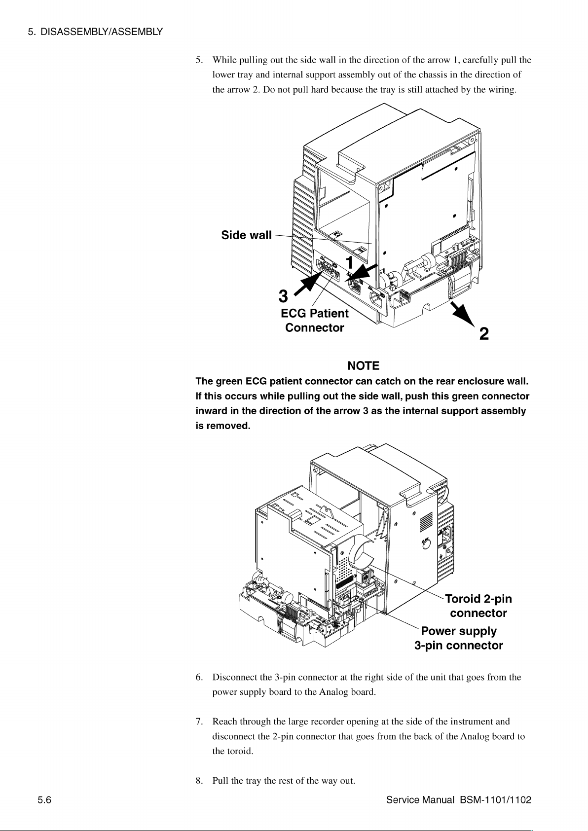
5.
DISASSEMBLY/ASSEMBLY
5.
While
lower
the
arrow
Side
pulling
tray
and
2.
Do
wall
out
the
side
wall
in
internal
——
support
not
pull
hard
assembly
because
ECG
Patient
Connector
the
direction
the
out
of
tray
of
the
is
the
chassis
still
attached
o
arrow
LESS
A
1,
carefully
in
the
by
1
y
pull
direction
the
Lo,
|
of
wiring.
the
The
green
If
this
inward
is
removed.
ECG
occurs
in
the
patient
while
direction
connector
pulling
of
out
the
the
arrow 3 as
NOTE
can
side
catch
wall,
the
on
the
push
this
internal
Power
3-pin
rear
enclosure
green
support
Toroid
connector
supply
connector
wall.
connector
assembly
2-pin
5.6
6.
Disconnect
power
7.
Reach
disconnect
the
8.
Pull
supply
through
toroid.
the
tray
the
the
the
3-pin
board
the
2-pin
rest
connector
to
the
large
recorder
connector
of
the
at
Analog
that
way
out.
the
right
board.
opening
goes
side
at
the
from
Service
of
side
the
the
of
back
Manual
unit
that
the
instrument
of
the
goes
from
and
Analog
BSM-1101/1102
board
the
to
Page 94
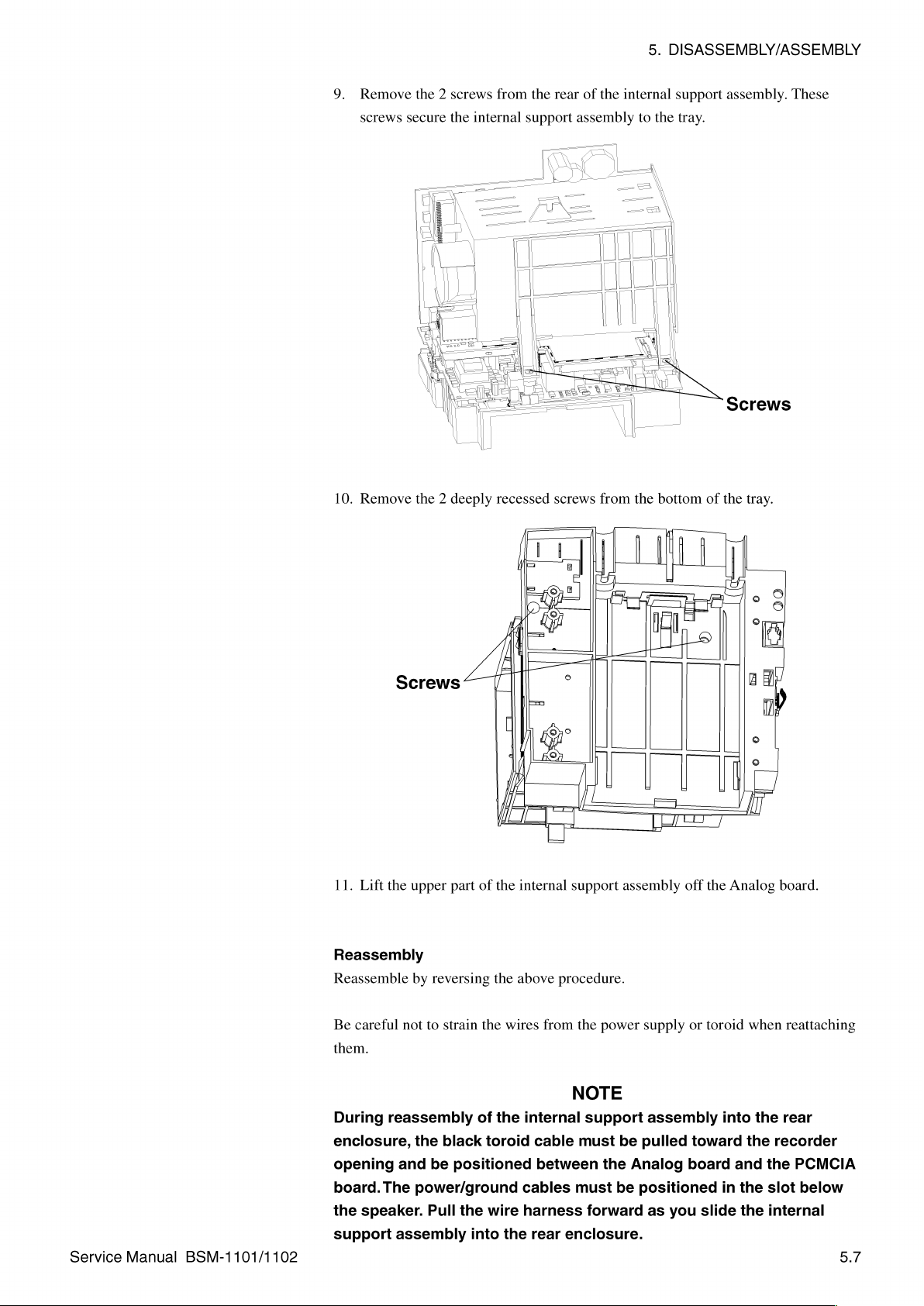
9.
Remove
screws
the 2 screws
secure
the
from
internal
the
rear
support
of
the
internal
assembly
5.
DISASSEMBLY/ASSEMBLY
to
support
the
tray.
assembly.
These
Service
Manual
BSM-1101/1102
Screws
11.
Lift the
Reassembly
Reassemble
Be
careful
them.
During
enclosure,
opening
board.
the
speaker.
support
upper
by
reversing
not
to
strain
reassembly
the
black
and
be
The
power/ground
Pull
assembly
part
of
the
the
the
wires
of
the
toroid
positioned
the
wire
into
the
internal
above
procedure.
from
internal
cable
between
cables
harness
rear
enclosure.
support
the
NOTE
support
must
must
forward
assembly
power
be
the
be
Analog
off
the
supply
or
toroid
assembly
pulled
positioned
as
you
toward
board
slide
Analog
when
into
the
and
in
the
the
board.
reattaching
the
rear
recorder
the
PCMCIA
slot
internal
below
5.7
Page 95

5.
DISASSEMBLY/ASSEMBLY
1.
Follow
the
instructions
in
the
“Opening
the
Instrument
LCD
LCD
Chassis”
retainer
section.
2.
3.
Remove
Remove
the 4 screws
the 3 screws
that
that
secure
secure
the
the
LCD
EMI
retainer
ground
and
remove
clips.
Rubber
boot
the
retainer.
5.8
EMI
ground
clips
BL
L-
Service
Manual
BSM-1101/1102
Page 96

4.
Lift
out
rubber
boot
the
LCD.
Reassembly
Replace
ground
Handle
fingerprints
between
the
LCD,
clips,
the
the
the
LCD
around
One
and
LCD
or
scratches.
LCD
unit
and
the
LCD.
side
of
the
place
the
rubber
reassemble
carefully
and
its
disconnect
(Note
LCD
case
boot
by
reversing
NOTE
so
that
it
Also,
be
lens.
the
ribbon
the
orientation
is
wider
on
the
new
the
above
does
not
sure
that
5.
DISASSEMBLY/ASSEMBLY
cable.
of
than
the
LCD,
procedure.
become
no
dust
Remove
the
other.)
reassemble
rubber
marked
gets
and
in
save
boot
around
the 3 EMI
by
the
space
the
Service
Manual
BSM-1101/1102
5.9
Page 97

5.
DISASSEMBLY/ASSEMBLY
1.
Follow
the
instructions
in
the
“Opening
the
Instrument
Chassis”
section.
Ribbon
2.
Remove
3.
Guide
from
Screws
cable
the
the
İRAT
|
|
|
4
the 4 screws
ribbon
cable
front
assembly.
i
K
SS
that
through
secure
the
the
front
slot
in
bezel.
the
front
bezel.
Remove
Screws
the
bezel
Front
Bezel
Light
Dark
gray
gray
HE
一
4.
Carefully
5.
Reposition
/
πι
|
|
[e
rs
=
[li
dal
1
peel
the
|
|
the
old
buttons
membrane
through
oo?
MBP
switch
the
appropriate
п,
ETC
一
assembly
openings
El
5
(|)
EY
¿pu
E
一
EH.
é
off
the
|
rear
in
=
>
of
the
the
bezel.
Orange
Dark
Light
bezel.
gray
gray
5.10
Service
Manual
BSM-1101/1102
Page 98

6.
Peel
the
7.
Carefully
To
prevent
avoid
peeling
8.
Press
the
Reassembly
1.
Feed
the
the
Encoder
2.
Reassemble
backing
from
position
decreased
off
the
switch
evenly
ribbon
cable
board.
by
reversing
the
new
the
new
reliability
assembly
to
the
through
the
membrane
membrane
NOTE
of
and
inside
the
slot
above
5.
switch
switch
assembly.
the
new
membrane
repositioning.
of
the
front
panel.
in
the
front
procedure.
DISASSEMBLY/ASSEMBLY
assembly.
bezel
switch
and
then
assembly,
to
the
left
of
Service
Manual
BSM-1101/1102
5.11
Page 99

5.
DISASSEMBLY/ASSEMBLY
1.
Follow
the
instructions
in
the
“Opening
the
Instrument
Chassis”
section.
2.
3.
4.
Encoder
PCB
Remove
Guide
from
the
Remove
Remove
the 4 screws
the
ribbon
front
assembly.
the 4 screws
the
LCD
E
Ji
lol
|
©
+.
0995
ㅁ
qo
Ek:
a
-
that
cable
through
that
assembly.
Е
JU!
6000000000000000
O
DOO0000000000000d0
000000000000000
bo0000000000000d
ΡΟΟΟΟΟΟΟΟΟΟΟΟΟΟΟ
000000000000000
00000000000000d
secure
secure
the
the
the
Г
=
front
slot
LCD
|
bezel.
in
the
retainer
NE
front
and
|
bezel.
set
LCD
Retainer
Remove
the
retainer
the
bezel
aside.
5.
At
the
Encoder
Encoder
Power
Switch
6.
Use a flat-blade
from
their
7.
Remove
8.
Slide
and
have
cleared
Reassembly
1.
Reconnect
2.
Replace
board,
board
to
the
board.
screwdriver
mounting
the 3 screws
pivot
the
Encoder
their
openings.
the
flat
flex
the
Encoder
disconnect
light
bar
shafts
and
that
secure
cables
board
and
the 2 small
assembly
to
loosen
remove
the
board
to
Lift the
before
reassemble
flat
and
from
the
upper
the
dials.
Encoder
the
Encoder
positioning
right
by
board.
until
board
reversing
flex
cables
the
Encoder
and
lower
the 3 volume
out
of
the
Encoder
the
that
go
from
board
to
multifunction
control
the
enclosure.
board.
above
procedure.
the
the
dials
knobs
5.12
Service
Manual
BSM-1101/1102
Page 100

1.
Follow
the
instructions
5.
DISASSEMBLY/ASSEMBLY
in
the
“Opening
the
Instrument
IX
Chassis”
Power
board
section.
Switch
2.
Atthe
Power
Switch
Power
3.
Remove
4.
Lift
out
5.
Remove
Reassembly
Install
the
procedure.
Switch
new
board
the 2 screws
the
Power
the
plastic
Power
board,
to
the
that
Switch
Power
Switch
disconnect
Encoder
secure
board.
switch
board
board.
the
Power
and
place
and
reassemble
the
flat
Switch
it
flex
cable
board.
on
the
new
by
reversing
that
goes
Power
the
from
Switch
above
the
board.
Service
Manual
BSM-1101/1102
5.13
 Loading...