


New Holland MZ19H REPAIR MANUAL


 REPAIR MZ19H MANUAL
87045364 2/04

MZ19H REPAIR MANUAL CONTENTS
SECTION 1 - GENERAL INFORMATION
SECTION 2 - MODEL/SERIAL NUMBER LOCATION
SECTION 3 - GREASING AND LUBRICATION
SECTION 4 - ENGINE
SECTION 5 - TRANSAXLE
SECTION 6 - CHASSIS
SECTION 7 - MOWER DECKS
SECTION 8 - ELECTRICAL SYSTEM
The sections used through out all New Holland product Repair manuals may not be used for each product. Each Repair manual will be made up of one or several books. Each book will be labeled as to which sections are in the overall Repair manual and which sections are in the each book.
The sections listed above are the sections utilized for the MZ19H series tractors.

SECTION 1 - GENERAL INFORMATION
SECTION 1 - GENERAL INFORMATION
|
CONTENTS |
|
Section |
Description |
Page |
|
General Information................................................................................................... |
1-2 |
|
Think Safety First....................................................................................................... |
1-2 |
|
Engine Specifications - (MZ19H)............................................................................... |
1-3 |
|
Bolt Torques............................................................................................................... |
1-7 |
|
Maintenance Schedule - (MZ19H)............................................................................. |
1-8 |
1-1

SECTION 1 - GENERAL INFORMATION
This symbol means WARNING or PERSONAL SAFETY INSTRUCTION - read the instruction because it has to do with your safety. Failure to comply with the instruction may result in personal injury or even death
This manual is intended as a service and repair manual only. The safety instructions provided herein are for troubleshooting, service, and repair of the MZ19H zero radius tractor. The MZ19H zero radius tractor and attachment operator's manuals contain safety information and operating tips for safe operating practices. Operator's manuals are available through your New Holland dealer.
THINK SAFETY FIRST
AVOID UNEXPECTED STARTING OF ENGINE...
Always turn off the engine and disconnect the spark plug wire(s) before cleaning, adjusting, or repair.
AVOID LACERATIONS AND AMPUTATIONS...
Stay clear of all moving parts whenever the engine is running. Treat all normally moving parts as if they were moving whenever the engine is running or has the potential to start.
AVOID BURNS...
Do not touch the engine, muffler, or other components which may increase in temperature during operation, while the unit is running or shortly after it has been running.
AVOID FIRES AND EXPLOSIONS...
Avoid spilling fuel and never smoke while working with any type of fuel or lubricant. Wipe up any spilled fuel or oil immediately. Never remove the fuel cap or add fuel when the engine is running. Always use approved, labeled containers for storing or transporting fuel and lubricants.
AVOID ASPHYXIATION...
Never operate an engine in a confined area without proper ventilation.
AVOID INJURY FROM BATTERIES...
Battery acid is poisonous and can cause burns. Avoid contact with skin, eyes, and clothing. Battery gases can explode. Keep cigarettes, sparks, and flames away from the battery.
AVOID INJURY DUE TO INFERIOR PARTS...
Use only original equipment parts to ensure that important safety criteria are met.
AVOID INJURY TO BYSTANDERS...
Always clear the area of bystanders before starting or testing powered equipment.
AVOID INJURY DUE TO PROJECTILES...
Always clear the area of sticks, rocks, or any other debris that could be picked up and thrown by the powered equipment.
AVOID MODIFICATIONS...
Never alter or modify any part unless it is a factory approved procedure.
AVOID UNSAFE OPERATION...
Always test the safety interlock system after making adjustments or repairs on the machine. Refer to the Electrical section in this manual for more information.
1-2

SECTION 1 - GENERAL INFORMATION
SPECIFICATIONS
|
MZ19H |
ENGINE |
|
Type............................................................... |
Kawasaki |
Model............................................................. |
FH580V |
Horsepower ................................................... |
14.2 kw (19)@3600 RPM |
Cylinders........................................................ |
V-Twin |
Displacement................................................. |
585CC (35.7 cu. in.) |
Low Idle Speed.............................................. |
1400 RPM |
Maximum Speed: |
|
High Idle .................................................... |
3400 RPM |
Oil Capacity ................................................... |
1.9 qt. (1.8L) |
Spec Number................................................. |
AS13 |
Fuel Unleaded Gasoline ................................ |
87 octane min. |
Vertical Shaft ................................................. |
1 in. (2.54 cm) Dia |
Charge coil .................................................... |
12v - 13 amp |
Other.............................................................. |
Air cooled, Dual element air cleaner, Fuel pump, |
|
Overhead valve, Four cycle, Electronic ignition, Full |
|
pressure lubricated with oil filter |
CONSTRUCTION |
|
Front Frame................................................... |
Welded 1 x 2 x .120 structural steel tube |
Rear Frame ................................................... |
Welded, 7 and 10 ga. high strength steel |
Frame Assembly............................................ |
Front and rear frames bolted together |
FUEL SYSTEM |
|
Capacity......................................................... |
5 Gallon (18.9 L) |
Type............................................................... |
Single fuel tank fender mounting on left side |
Other.............................................................. |
Fuel tank shut-off, Fuel filter (replaceable in-line type), |
|
Large diameter vented fuel cap, Tank includes molded |
|
beverage holder |
TRACTION SYSTEM |
|
Transaxles ..................................................... |
Twin Hydro-Gear Hydrostatic Transaxles |
Transaxle Drive ............................................. |
Belt drive with self-tensioning system |
Ground speed................................................ |
Infinite, 0 to 7-MPH (10.5-km/hr) forward, 0 to 3.4-MPH |
|
(5.5-km/hr) reverse |
Transport Rods.............................................. |
Allow unit to be moved without engine running |
ATTACHMENT DRIVE |
|
Clutch ............................................................ |
Electric Clutch |
Type............................................................... |
Vertical drive with single deep B-groove Pulley |
1-3

SECTION 1 - GENERAL INFORMATION
|
MZ19H |
TIRES |
|
Rear Drive Tires ............................................ |
18 x 10.5-10 4 ply with “Multitrac CS” tread |
Front Castor Tires.......................................... |
410/350 x 4 with “sawtooth” tread |
Tire Pressure ................................................. |
13 psi (90 kPa), rear, 35 psi (241 kPa) front |
OPERATORS SEAT |
|
Type............................................................... |
High back foam padded with arm rests |
Mounting........................................................ |
Hinged mounting for easy access to battery and controls; |
|
spring suspension |
Adjustment..................................................... |
Fore and aft 3 in. (76 mm) by loosening 2 knobs and |
|
sliding seat |
STEERING |
|
Levers............................................................ |
Dual wrap-around levers control hydraulic pumps |
Dampening .................................................... |
Dual hydraulic dampers |
Turning Radius .............................................. |
Zero radius turn (ZRT) |
CONTROLS |
|
Steering Lever ............................................... |
Dual wrap-around with cushioned grips |
Parking Brake ................................................ |
Left hand operated lever with cushioned grip |
Attachment Lift............................................... |
Right hand operated lever with cushioned grip |
Cutting Height................................................ |
Rightside incorporated with attachment lift |
Engine Throttle .............................................. |
Rightside console mounted lever |
Ignition Switch ............................................... |
Rightside console mounted electric with key |
Power Take Off .............................................. |
Rightside console mounted electric |
INTERLOCKS |
|
Seat ............................................................... |
Operator presence switch |
Control Lever ................................................. |
Dual neutral sensing switch |
Power Take Off .............................................. |
Position switch |
Brake ............................................................. |
Position switch |
ELECTRICAL SYSTEM |
|
Battery Voltage .............................................. |
12 volt negative ground |
Battery Type .................................................. |
BCI Group U1 |
Fused............................................................. |
(1) 30 amp blade type, main |
|
(1) 25 amp blade type, charge system |
|
(1) 10 amp (blade type) included with optional light kit |
1-4

SECTION 1 - GENERAL INFORMATION
MZ19H
LUBRICATION FITTINGS |
|
|
Front Castor Pivots........................................ |
2 |
Fittings |
Front Castor Wheels...................................... |
2 |
Fittings |
Lift Assembly ................................................. |
3 Fittings |
|
Deck Idler Pivot ............................................. |
1 |
Fitting |
Transaxle Idler Pivot...................................... |
1 |
Fitting |
Control Linkage Pivot .................................... |
2 |
Fittings |
DIMENSIONS |
|
Wheel Base ................................................... |
52.1 in. (132.3 cm) center of castor to center of drive tires |
Width ............................................................. |
47.6 in. (120.9 cm) outside rear tires |
Overall Width ................................................. |
65 in. (165.1 cm) with deck deflector down |
|
58 in. (147.3 cm) Gate width with deck deflector up. |
Overall Length ............................................... |
77.5 in. (196.9 cm) |
Overall Height................................................ |
41 in. (104.1 cm) |
Track Width ................................................... |
37.5 in. (95.3 cm) center to center of rear tires |
|
30.4 in. (77.2 cm) center to center of castor tires |
Deck Width .................................................... |
65 in. (165.1 cm) w/deflector down |
WEIGHT |
|
Net Weight |
680 lbs. (309 kg) (estimated) |
DECK |
Right side discharge. 52 in. (132 cm) cut, three blade |
|
mid-mounted rotary. Drawn 12 gauge steel deck with |
|
welded mounting brackets and gauge wheel brackets. |
|
Frame supported. |
DECK BELT COVERS |
Removable 16 gauge formed sheet metal, fastened to |
|
deck with thread forming screws. Access holes in top for |
|
greasing spindles. |
DEFLECTOR |
12 gauge formed, held down by torsion springs at pivot |
|
bracket. |
ANTI-SCALP ROLLERS |
One front mounted |
DECK OFFSET |
None. Deck centerline on machine centerline. |
1-5

SECTION 1 - GENERAL INFORMATION
|
MZ19H |
GAUGE WHEELS |
One on each front corner, one on each rear corner to |
|
reduce scalping. Gauge wheels have four height position |
|
adjustments. |
HEIGHT OF CUT |
Adjusts from 1.5” to 4.5” (38 to 114 mm) (7 positions) |
UNCUT CIRCLE |
0” uncut circle |
ENGINE TO DECK DRIVE |
HB-section Kevlar cord “V” belt from engine clutch |
|
sheave to deck spindle sheaves. Spring loaded idler for |
|
belt tension and take-up |
SPINDLE ASSEMBLIES |
Three 17-mm diameter spindles turning in permanently |
|
lubed ball bearings. Die cast aluminum spindle housings. |
BLADES |
Three 18” x 2.5” x .187” heat treated steel blades |
TIP SPEED |
17,500 ft/min (5334 m/min) @ 3400 RPM nominal |
|
18,070 ft/min (5507 m/min) @ 3500 RPM max |
DECK MOUNTING |
Deck suspended from front frame by four trunnion rods |
|
and attached to lift mechanism by two multi-position links |
|
(“pork chops”). |
OPTIONAL EQUIPMENT |
|
Recycler Kit |
|
Light Kit |
|
Snow Plow Attachment |
|
Tire Chains |
|
Smooth Castor Wheel Kit |
|
Striping Kit |
|
Decal Kit - Canada |
|
CERTIFICATION |
Conforms to California CARB and EPA Certification. |
|
Conforms to ANSI B71.1-2001 |
1-6

SECTION 1 - GENERAL INFORMATION
BOLT TORQUES
DESCRIPTION |
|
TORQUE |
|
|
|
Blade to Spindle |
80 |
- 100 ft lb (109 - 136 N·m) |
Caster Bolts |
77 |
- 95 ft lb (105 - 130 N·m) |
Clutch Bolt |
50 |
- 60 ft lb (68 - 82 N·m) |
Engine Mounting Bolts |
120 - 180 ft lb (164 - 246 N·m) |
|
Spindle Pulley Nuts |
80 |
- 100 ft lb (109 - 136 N·m) |
Wheel Lug Nuts |
70 |
- 90 ft lb (95.5 - 123 N·m) |
1-7

SECTION 1 - GENERAL INFORMATION
MAINTENANCE SECHUDLE (MZ19H)
MAINTENANCE PROCEDURE |
SERVICE INTERVAL |
|
|
|
|
Check the engine oil |
After first use |
|
Check the engine oil level |
|
|
Check the safety system |
Each use |
|
Clean the air intake screen |
||
|
||
Clean the mower housing |
|
|
Check the cutting blades |
Every 5 hours |
|
Grease all lubrication points1 |
|
|
Oil the linkage bushings1 |
|
|
Service the foam air cleaner1 |
Every 25 hours |
|
Check the belts for wear/cracks |
|
|
Check the battery electrolyte |
|
|
Check the tire pressure |
|
|
Service the paper air cleaner1 |
Every 50 hours |
|
Change the engine oil |
Every 100 hours |
|
Check the spark plug(s) |
||
Change the oil filter1 |
Every 200 hours |
|
Replace the fuel filter |
||
|
||
Replace the paper air cleaner1 |
|
|
Clean the engine shrouds and cooling fins1 |
Every 300 hours |
|
Before Storage: |
|
|
• Perform all maintenance procedures listed above. |
|
|
• Drain the fuel tank. |
|
|
• Charge the battery and disconnect the battery cables. |
|
|
• Paint any chipped surfaces. |
|
|
|
|
1More often in dusty, dirty conditions
IMPORTANT: Refer to your engine operator’s manual for additional maintenance procedures.
CAUTION
If you leave the key in the ignition switch, someone could accidently start the engine and seriously injury you or other bystanders.
Remove the key from the ignition and disconnect the wire from the spark plug(s) before you do any maintenance. Set the wire aside so that it does not accidentally contact the spark plug.
1-8
SECTION 2 - MODEL/SERIAL NUMBER LOCATION
SECTION 2 - MODEL/SERIAL NUMBER LOCATION
|
|
CONTENTS |
Section |
Description |
Page |
|
Model/Serial Number Location |
.................................................................................. 2-2 |
2-1
SECTION 2 - MODEL/SERIAL NUMBER LOCATION
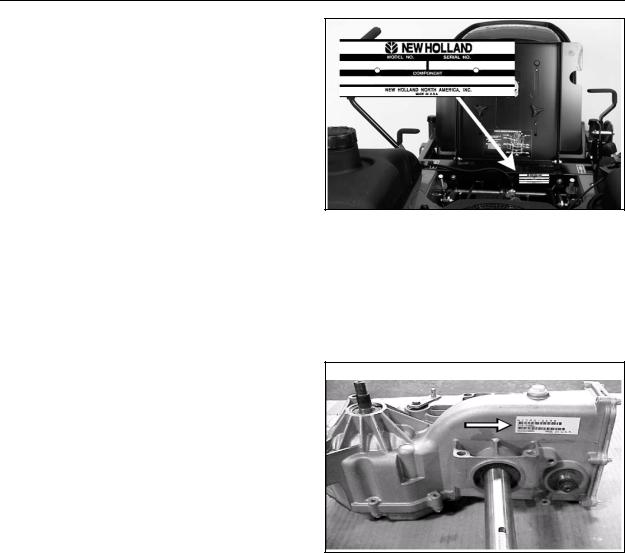
MODEL/SERIAL NUMBER LOCATION
The unit model and serial number plates is on the frame under the seat as shown in the illustration.
The engine has its own model and serial number identification. Consult the appropriate engine manufacture’s service literature for the location and translation of the engine model and serial number information.
Transaxles also have their own model/serial number.
2-2

SECTION 3 - GREASING AND LUBRICATION
SECTION 3 - GREASING AND LUBRICATION
|
|
CONTENTS |
Section |
Description |
Page |
|
Service Interval/Specification |
.................................................................................... 3-2 |
|
Lubrication Points ...................................................................................................... |
3-3 |
3-1

SECTION 3 - GREASING AND LUBRICATION
SERVICE INTERVAL/SPECIFICATION
The unit should be greased every 25 hours; more often when operating in dirty, dusty, or sandy conditions.
A decal located under the seat shows the location of all the grease zerks.
Grease Type: New Holland Ambra GR-9 multipurpose grease (General-purpose lithium base grease).
3-2
SECTION 3 - GREASING AND LUBRICATION
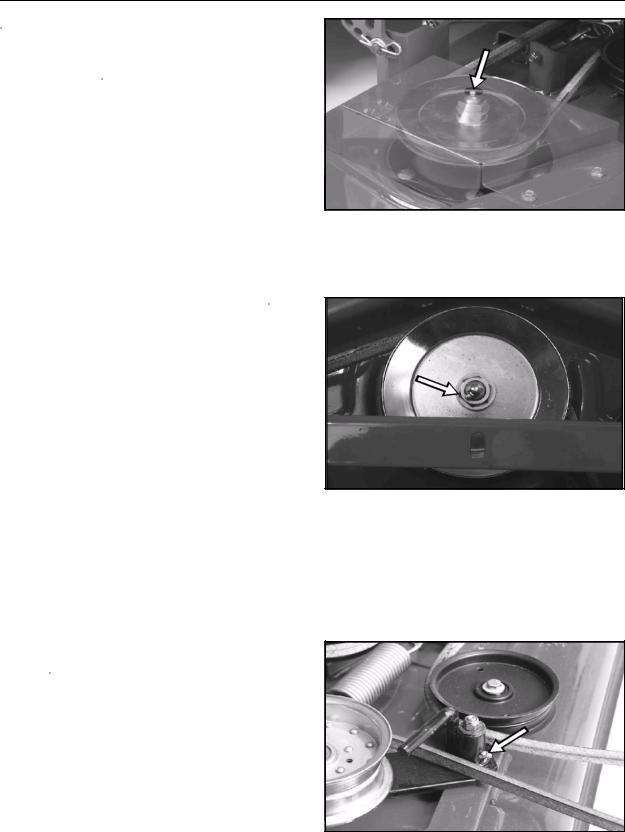
LUBRICATION POINTS
There is a grease fitting on the mower for right and left outer spindle.
The grease zerk for the center mower spindle.
There is a grease fitting for the deck idler arm bushing.
3-3

SECTION 3 - GREASING AND LUBRICATION
There are two grease fittings for the deck raising pivot bushings - one on each side of the unit.
The grease zerk for the deck height adjustment lever is on the right side of the machine.
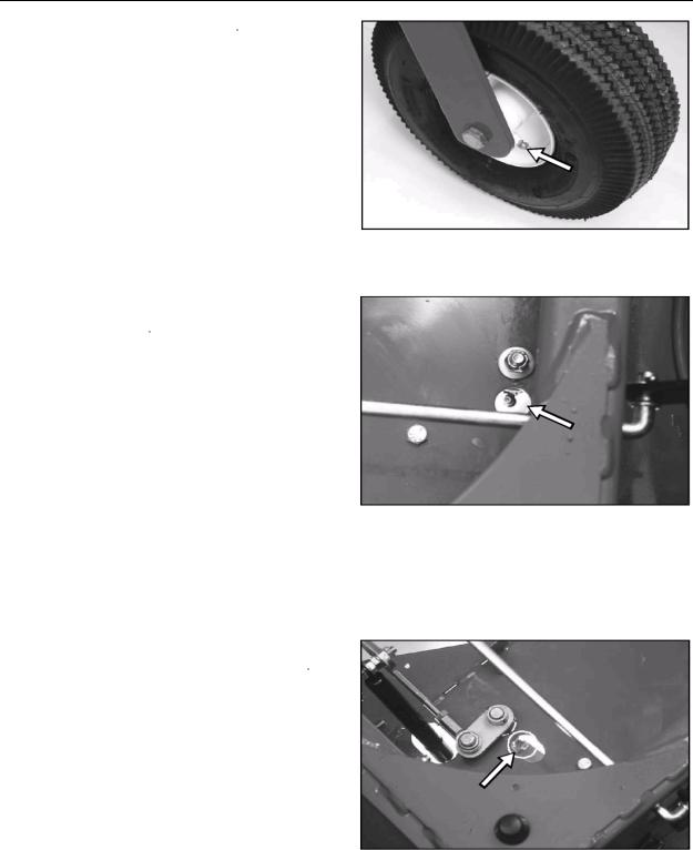
There are grease fittings for each front castor bushing,
3-4
SECTION 3 - GREASING AND LUBRICATION
as well as the castor wheel bearings.
The zerk fitting for the traction belt idler bushing is located under the seat.
Also under the seat are the fittings for the motion control lever pivot bushings - one for each lever.
3-5

SECTION 3 - GREASING AND LUBRICATION
3-6

SECTION 4 - ENGINE
SECTION 4 - ENGINE
|
|
CONTENTS |
Section |
Description |
Page |
|
Kawasaki Engine ....................................................................................................... |
4-2 |
|
Kawasaki Air Cleaner ................................................................................................ |
4-2 |
|
Spark Plug ................................................................................................................. |
4-3 |
|
Engine Remove and Replace.................................................................................... |
4-4 |
4-1
SECTION 4 - ENGINE
KAWASAKI ENGINE
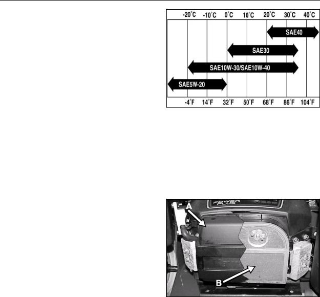
Oil Type: New Holland Ambra Super Gold detergent oil (API service SC, SD, SE, SF, SG, or SH).
Crankcase Capacity (with filter): 1.6 qt. (1.5 l).
Viscosity: See table.
Change Oil:
•After the first use.
•Every 100 hours.
Change oil filter every 200 hours.
KAWASAKI AIR CLEANER
The air cleaner assembly consists of a paper filter element and a foam precleaner.
To clean the paper element, tap lightly on a flat surface to remove dust and dirt. Inspect the element for tears, oil contamination, and damage to the rubber seal.
NOTE: Never clean the paper element with compressed air or solvents. If the element is dirty or damaged, replace it immediately.
(A)COVER
(B)AIR FILTER
4-2
SECTION 4 - ENGINE
Every 25 hours (more often in dusty, dirty conditions), wash the foam element in liquid soap and warm water. When the element is clean, rinse it thoroughly.
Dry the element by squeezing it in a clean cloth (do not wring). Allow the element to air dry.
Follow engine manufacturer’s recommendation for treatment of precleaner prior to installation.
SPARK PLUG
On Kawasaki engines, replace the spark plug(s) every 100 operating hours.
If the insulator on the spark plug(s) is light brown or gray, the engine is running properly. A black coating on the insulator indicates the air cleaner may be dirty.
IMPORTANT: Never clean the spark plug(s). Always replace the spark plug(s) when it has a black coating, worn electrodes, an oily film, or cracks.
Gap: .030” (0.76 mm)
Type: Champion RCJ86 (or equivalent)
4-3
SECTION 4 - ENGINE
ENGINE REMOVE AND REPLACE
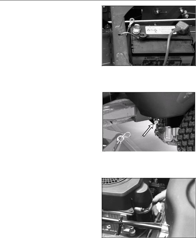
Disconnect the negative battery cable.
Close the fuel shut-off.
Remove the fuel line from the fuel filter.
4-4
SECTION 4 - ENGINE
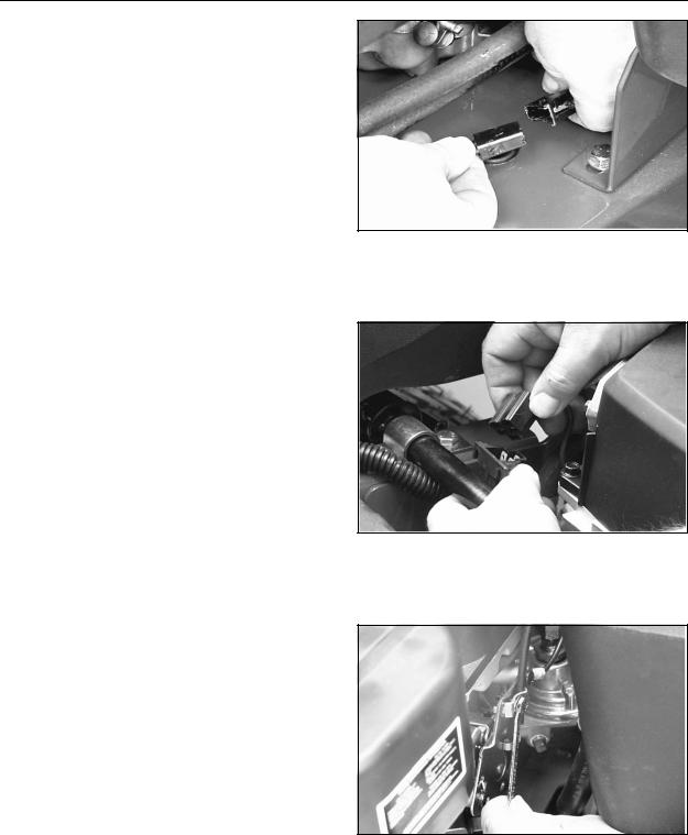
Disconnect the clutch PTO wiring.
Disconnect the engine wiring harness plug.
Loosen the throttle/choke clamp and remove the cable from the governor linkage.
4-5
SECTION 4 - ENGINE
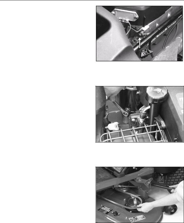
Remove the ground cable from the engine block.
Remove the starter cable.
Remove mower drive belt. See complete procedure in Section 7, Mower Decks.
4-6

SECTION 4 - ENGINE
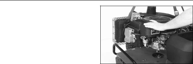
Remove the clutch bolt and lower the clutch assembly.
Remove traction drive belt.
Move the idler pulley to lessen the tension on the traction drive belt and slip the belt up off the engine drive pulley. Then remove the clutch and drive pulley from the crankshaft.
Remove the 4 engine mounting bolts.
4-7
SECTION 4 - ENGINE
Lift the engine from the chassis.
Reverse the above steps to replace.
4-8

SECTION 5 - TRANSAXLE
SECTION 5 - TRANSAXLE
|
CONTENTS |
|
Section |
Description |
Page |
|
Description and Operation......................................................................................... |
5-2 |
|
General Description................................................................................................... |
5-2 |
|
Hydraulic Schematic.................................................................................................. |
5-3 |
|
Technical Specifications ............................................................................................ |
5-6 |
|
Product Identification ................................................................................................. |
5-6 |
|
Troubleshooting Checklist ......................................................................................... |
5-7 |
|
Fluids ......................................................................................................................... |
5-9 |
|
Fluid Change ............................................................................................................. |
5-9 |
|
Control Handle-Return To Neutral Adjustment ........................................................ |
5-10 |
|
Purging the System ................................................................................................. |
5-12 |
|
Neutral Adjustment .................................................................................................. |
5-14 |
|
Tracking Adjustment ................................................................................................ |
5-18 |
|
Control Handle Adjustment...................................................................................... |
5-20 |
|
Remove and Replace Transaxle ............................................................................. |
5-21 |
|
Reassembly............................................................................................................. |
5-26 |
|
Repair ...................................................................................................................... |
5-30 |
|
General Instructions ................................................................................................ |
5-30 |
|
Limited Disassembly................................................................................................ |
5-30 |
|
Back Cover .............................................................................................................. |
5-32 |
|
Brakes ..................................................................................................................... |
5-33 |
|
Brake Shaft and Bevel Gear.................................................................................... |
5-34 |
|
Axle Shaft and Spur Gear........................................................................................ |
5-35 |
|
Lower Housing and Filter......................................................................................... |
5-37 |
|
Motor Shaft and Bevel Gear .................................................................................... |
5-38 |
|
Center Section, Cylinder Blocks and Bypass .......................................................... |
5-39 |
|
Input Shaft and Trunnion Arm.................................................................................. |
5-41 |
|
Sealant Application.................................................................................................. |
5-43 |
5-1
SECTION 5 - TRANSAXLE
DESCRIPTION AND OPERATION
This manual includes the transaxle general description, hydraulic schematic, technical specifications, servicing and troubleshooting procedures.
The transaxle normally will not require servicing during the life of the vehicle in which it is installed. Should other servicing be required, the exterior of the transaxle will need to be thoroughly cleaned before beginning most procedures.
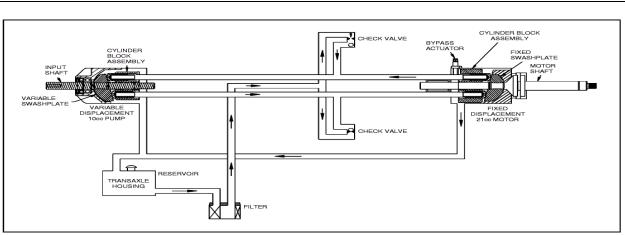
GENERAL DESCRIPTION
The transaxle is a self contained unit designed for the transfer and control of power. It provides an infinitely variable speed range between zero and maximum in both forward and reverse modes of operation.
This transaxle uses a variable displacement pump with a maximum displacement of 10cc per revolution, and motor with a fixed displacement of 21cc per revolution. The variable displacement pump features a cradle mounted swashplate with a direct-proportional displacement control. Reversing the direction of the swashplate reverses the flow of oil from the pump an thus reverses the direction of the motor output rotation. The pump and motor are
of the axial piston design and utilize spherical nosed pistons which are held against a thrust race by internal compression springs.
The transaxle has a self contained fluid supply and an internal filter. The fluid is forced through the filter by a positive “head” on the fluid in the housing/ expansion tank with an assist by the negative pressure created in the pump pistons as they operate.
The check valves in the center section are used to control the makeup flow of the fluid to the low pressure side of the loop.
A bypass is utilized in this unit to permit moving the vehicle for a short distance at a maximum of 2 m.p.h. (3.2 Km/h) without starting the engine.
 WARNING
Actuating the bypass will result in the loss of hydrostatic braking capacity. The machine must be stationary on a level surface and in neutral when actuating the bypass.
5-2
SECTION 5 - TRANSAXLE
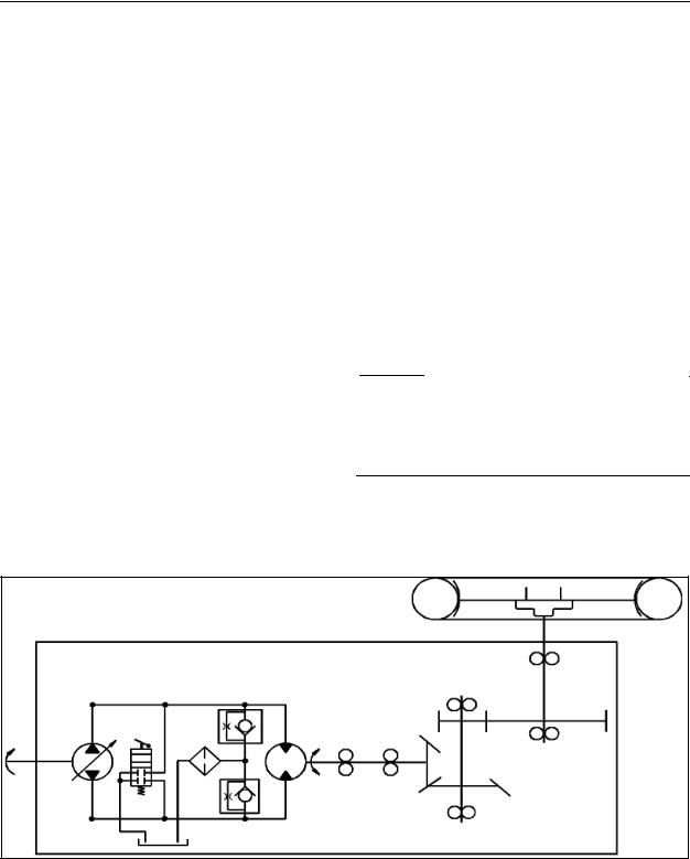
HYDRAULIC SCHEMATIC
The illustration above provides a flow diagram of the hydraulic oil circuit. The oil supply for the hydraulic system of the transaxle is also utilized for lubricating the components of the final drive assembly.
The input shaft and pump cylinder block are turned in one direction only by the engine/drive belt/pulley combination. Output of the oil flow is controlled by the direction and amount that the variable swashplate is angled. As the pump pistons compress they force the oil to flow through one of two passageways (forward or reverse) in the center section to the motor cylinder block and motor shaft. Since the motor has fixed displacement angle it is forced to turn with the flow of oil. As the angle of the pump swashplate is increased the amount of oil being pumped will increase and cause a higher speed output of the motor. Reversing the angle of the swashplate will reverse the direction of oil flow.
During the operation of the transaxle, fluid is “lost” from the hydraulic loop through leak paths designed into the product for lubrication purposes (around pistons, under the rotating cylinder blocks, etc.). This “lost” fluid returns to the transaxle housing, then is pulled back into one of the check valves depending upon the direction of vehicle operation. All of this oil must pass through an internal filter.
The motor cylinder block mounts onto a splined motor shaft which drives the gear train.
The bypass feature in the transaxle has a mechanical lever which lifts the motor block off of the center section running surface, allowing any oil flowing from the pump block to be discharged into the housing without turning the motor.
5-3

SECTION 5 - TRANSAXLE
5-4
 Loading...