

NEC WMK-3255S User Manual
1
2014-01-08 #:125-9484-6 (2017-04-06)
ENG
32" - 80"
(81 - 203 cm)
125 lb
(57 kg)
MAX
WMK-3255S
2
2014-01-08 #:125-9484-6 (2017-04-06)
5mm
(3/16")
ENG - This product is designed to be installed on wood stud, solid concrete or cinder block walls. Hardware is
included for wood stud, solid concrete and cinder block installation. Before installing make sure the supporting
surface will support the combined load of the equipment and hardware. Screws must be tightly secured. Do
not overtighten screws or damage can occur and product may fail. Never exceed the Maximum Load Capacity.
Always use an assistant or mechanical lifting equipment to safely lift and position equipment. This product is
intended for indoor use only. Use of this product outdoors could lead to product failure or personal injury. Be
careful not to pinch fi ngers when operating the mount. For support please call customer care at 1-800-865-2112.
WARNING
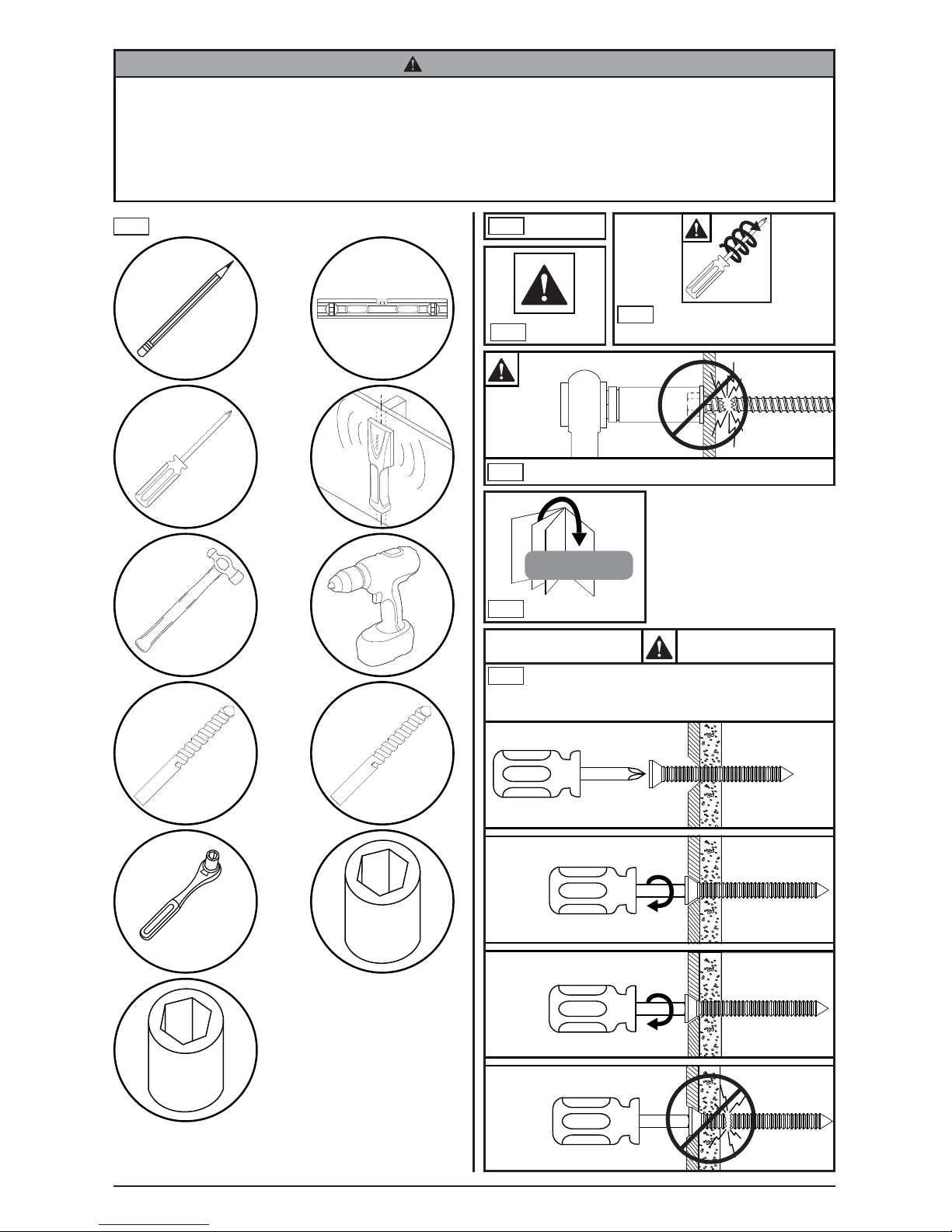
Tools Needed for Assembly.
ENG
1
2
ENG
To properly tighten screws: Tighten until screw
head makes contact, then tighten another 1/2
turn. Do not overtighten screws.
+1/2
4
3
5/32"
(4mm)
5/16"
(8mm)
3/8"
(10mm)
Symbols
ENG
WARNING
ENG
#
Skip to step.
ENG
x3
Screws must get at least
three full turns and fi t snug.
ENG
Do not overtighten screws.
ENG
3
2014-01-08 #:125-9484-6 (2017-04-06)
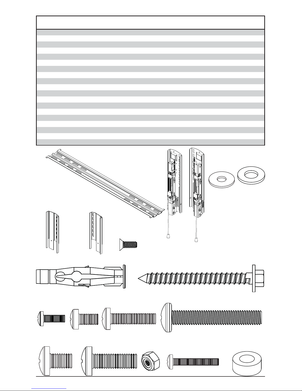
F (1)
right extension plate
G (1)
left extension plate
C (1)
left adapter
bracket
right adapter
bracket
B (1)
A (1)
wall plate
D
(2)
concrete anchor
E
(2)
#14 x 2-1/2" wood screw
I (4)
M6 x 12 mm
M8 x 12 mm
K (4)
M8 x 25 mm
M4 x 25mm
L (4)
O (4)
N (2)
nut
M (2)
fl at head screw
Parts List
Part #Description Qty
A wall plate 1 202-1008
B left adapter bracket 1 202-1621
C right adapter bracket 1 202-1622
D concrete anchor 2 590-0320
E #14 wood screw 2 5S1-015-C03
F left extension plate 1 202-1016
G right extension plate 1 202-1017
H M4 x 12 mm phillips screw 4 504-9013
I M6 x 12 mm phillips screw 4 520-1128
J M6 x 25 mm phillips screw 4 520-1208
K M8 x 12mm phillips screw 4 520-9571
L M8 x 25 mm phillips screw 4 520-1031
M 6-32" fl at head screw 2 520-1793
N 6-32" nylock nut 2 530-1006
O M4 x 25mm phillips screw 4 504-1015
P spacer 8 600-1215
R 5/16" washer 8 540-9406
S #10 washer (not used) 4 540-9400
T M8 x 50mm 4 521-1009
P (8)
spacer
H (4)
M4 x 12mm
J (4)
M6 x 25 mm
R (8)
5/16" washer
S (4)
#10 washer
(not used)
T
(4)
M8 x 50mm
4
2014-01-08 #:125-9484-6 (2017-04-06)
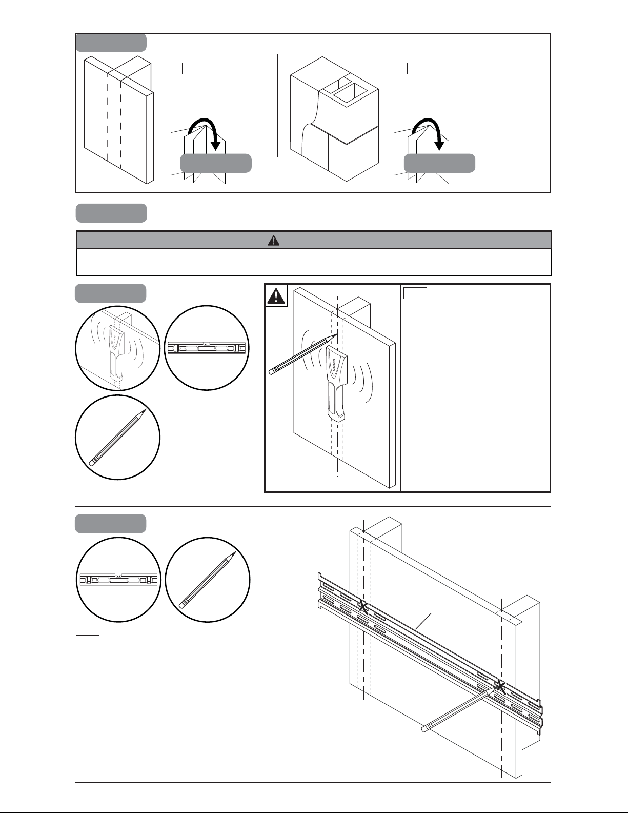
1a-1
Use stud fi nder to locate and
mark stud center lines.
ENG
1
1b1a
Wood stud wall
ENG
Concrete/Cinder block
ENG
1a
1a-2
Level wallplate. Mark mounting holes on stud
center lines.
ENG
A
ENG - When installing Peerless wall mounts on a wood stud wall covered with gypsum board (drywall), verify that
the wood studs are a minimum of 2" x 4" nominal size. Do not install over gypsum board thicker than 5/8".
WARNING
 Loading...