

Page 1
NEC Solutions (America), Inc.
Visual Systems
WT610™ Installation Guide
Desktop and Ceiling Mount v1.7
Contents
Product Description, Lens Specs, Notes and Formulas Page 1
Diagrams and Distance Charts
Ceiling Mounted Installation
Desktop Setup
Cabinet Dimensions
Top, Front and Right Side
Bottom, Back and Left Side
Optional Ceiling Mount Dimensions
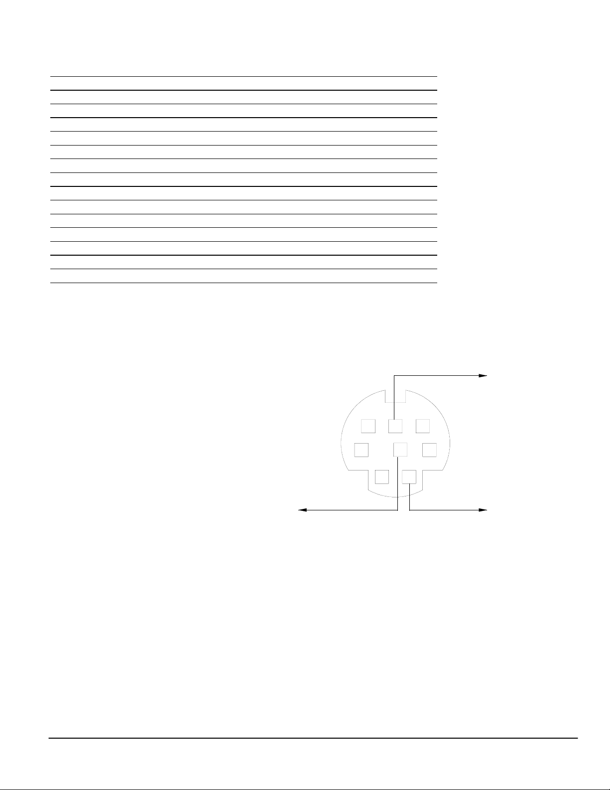
Control Codes
Product Description
Type: 1 chip DMDTM Lens-less projector Dimensions: 15.0”(W) x 12.3”(H) x 12.3”(D) w/final mirror up
4 mirror bounce optical system Weight: 14.1 lbs
Native Resolution: 1024 x 768 (1024x768 for 16:9 screens Screen Range: 40” – 100” Diagonal (4:3)
Brightness: 2000 lumens (1500 ANSI)
Screen/Aspect Ratio_
Both 4:3 and 16:9 screens are fully supported with proper aspect ratio control for bo th type sources using NEC developed
scaling technology. By selecting the screen type in the menus, Aspect Ratio control is reconfigured for that screen type.
• For a 4:3 screen; select “4:3” in the “Screen” menu for proper aspect ratio control of 4:3 and 16:9 sources.
• For a 16:9 screen; select “16:9” in the “Screen” menu for proper aspect ratio control of 4:3 and 16:9 sources.
Factory default “Screen” setting is “4:3”.
Notes
For screen sizes not indicated on the projection charts, use the formulas below.
The ceiling must be strong enough to support the projector and the instal lation must be in accordance with any local
building codes.
• Distances are in inches, for millimeters multiply by 25.4.
• Distances may vary ±5%.
Formulas
The Projection Formulas use the image width for calculation. Image width is the same for all aspect ratios, only vertical image size
varies. For proper projector placement, determine the image width for a desired screen size. Use the Screen Formulas below to
calculate all screen dimensions. Plug the screen width in for “W” in the Projection Formulas.
Refer to the diagrams and charts for popular screen sizes on page 2 and 3.
Definitions:
W = Screen width W = H x 4/3
H = Screen height H = W x 3/4
B = Vertical distance between projector foot and screen center Screen Diagonal = W x 5/4
C = Throw distance
D = Vertical distance between projector foot and screen bottom
(screen top for ceiling mounted application) 16:9 Screen Formulas:
W = H x 16/9
H = W x 9/16
Projection Formulas:
B = 0.6882W + 3.935
C = 0.4874W - 13.056
D(4:3) = 0.3132W + 3.935
D(16:9) = 0.407W + 3.935
Vertical Position for a 16:9 screen: The Vertical Position adjustment moves the 16:9 image up and down in the unused portion of
the 4:3 DLP panel. This adjustment is only available when the projector is set for 16:9 in the “Screen” menu. The range of Vertical
Position is dependent on aspect ratio and 3D Reform used. If 3D Reform is not used, the approximate range of vertical position is
+/-0.167H (H=Screen Height) when using a 16:9 screen. (See “Screen Type” and “Position” in user manual)
4:3 Screen Formulas:
Screen Diagonal = W x 18.358/16
Page 2
Page 3
Page 4
Page 5
Page 6
Page 7
www.necvisualsystems.com WT610 Page 1 of 7
Page 2
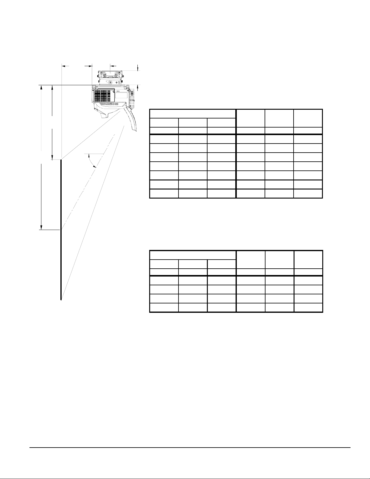
Ceiling Mounted Installation
The following diagram shows the relationship bet ween projector position and the screen. Refer to the charts below for data.
Distances are in inches. For millimeters multiply by 25.4.
C
5.1"
4.1"
Distance chart for popular 4:3 screen sizes
D
B
55°
Image Size (4:3)
Diagonal Width(W) Height(H)
inches inches inches inches inches inches
BCD
40 32 24 26.0 2.5 14.0
60 48 36 37.0 10.3 19.0
67 53.6 40.2 40.8 13.1 20.7
72 57.6 43.2 43.6 15.0 22.0
84 67.2 50.4 50.2 19.7 25.0
90 72 54 53.5 22.0 26.5
100 80 60 59.0 25.9 29.0
(4:3)
Distance chart for popular 16:9 screen sizes
Vertical Position for a 16:9 screen: The Vertical Position adjustment moves the 16:9 image
up and down in the unused portion of the 4:3 DLP panel. This adjustment is only available when
the projector is set for 16:9 in the “Screen” menu. The range of Vertical Position is dependent
on aspect ratio and 3D Reform used. If 3D Reform is not used, the approximate range of
vertical position is +/-0.167H (H=Screen Height) when using a 16:9 screen. (See “Screen Type”
and “Position” in user manual)
Note: For screen sizes not indicated in the distance charts, use the formulas on page 1.
Image Si ze (16: 9)
Diagonal Width(W) Height(H)
inches inches inches inches inches inches
BC
D
37 32 18 26.0 2.5 17.0
40 35 19.7 28.0 4.0 18.2
83 72 40.5 53.5 22.0 33.2
92 80 45 59.0 25.9 36.5
(16:9)
www.necvisualsystems.com WT610 Page 2 of 7
Page 3
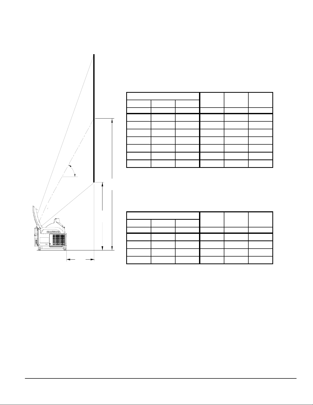
Desktop Setup
The following diagram shows the relationship bet ween projector position and the screen. Refer to the charts below for data.
Distances are in inches. For millimeters multiply by 25.4.
Distance chart for popular 4:3 screen sizes
5°
5
B
Image Size (4:3)
Diagonal Width(W) Height(H)
inches inches inches inches inches inches
BCD
40 32 24 26.0 2.5 14.0
60 48 36 37.0 10.3 19.0
67 53.6 40.2 40.8 13.1 20.7
72 57.6 43.2 43.6 15.0 22.0
84 67.2 50.4 50.2 19.7 25.0
90 72 54 53.5 22.0 26.5
100 80 60 59.0 25.9 29.0
(4:3)
Distance chart for popular 16:9 screen sizes
Note: For screen sizes not indicated in the distance charts, use the formulas on page 1.
C
D
Vertical Position for a 16:9 screen: The Vertical Position adjustment moves the 16:9 image
up and down in the unused portion of the 4:3 DLP panel. This adjustment is only available when
the projector is set for 16:9 in the “Screen” menu. The range of Vertical Position is dependent
on aspect ratio and 3D Reform used. If 3D Reform is not used, the approximate range of
vertical position is +/-0.167H (H=Screen Height) when using a 16:9 screen. (See “Screen Type”
and “Position” in user manual)
Image Size (16:9)
Diagonal Width(W) Height(H)
inches inches inches inches inches inches
BC
D
37 32 18 26.0 2.5 17.0
40 35 19.7 28.0 4.0 18.2
83 72 40.5 53.5 22.0 33.2
92 80 45 59.0 25.9 36.5
(16:9)
www.necvisualsystems.com WT610 Page 3 of 7
Page 4
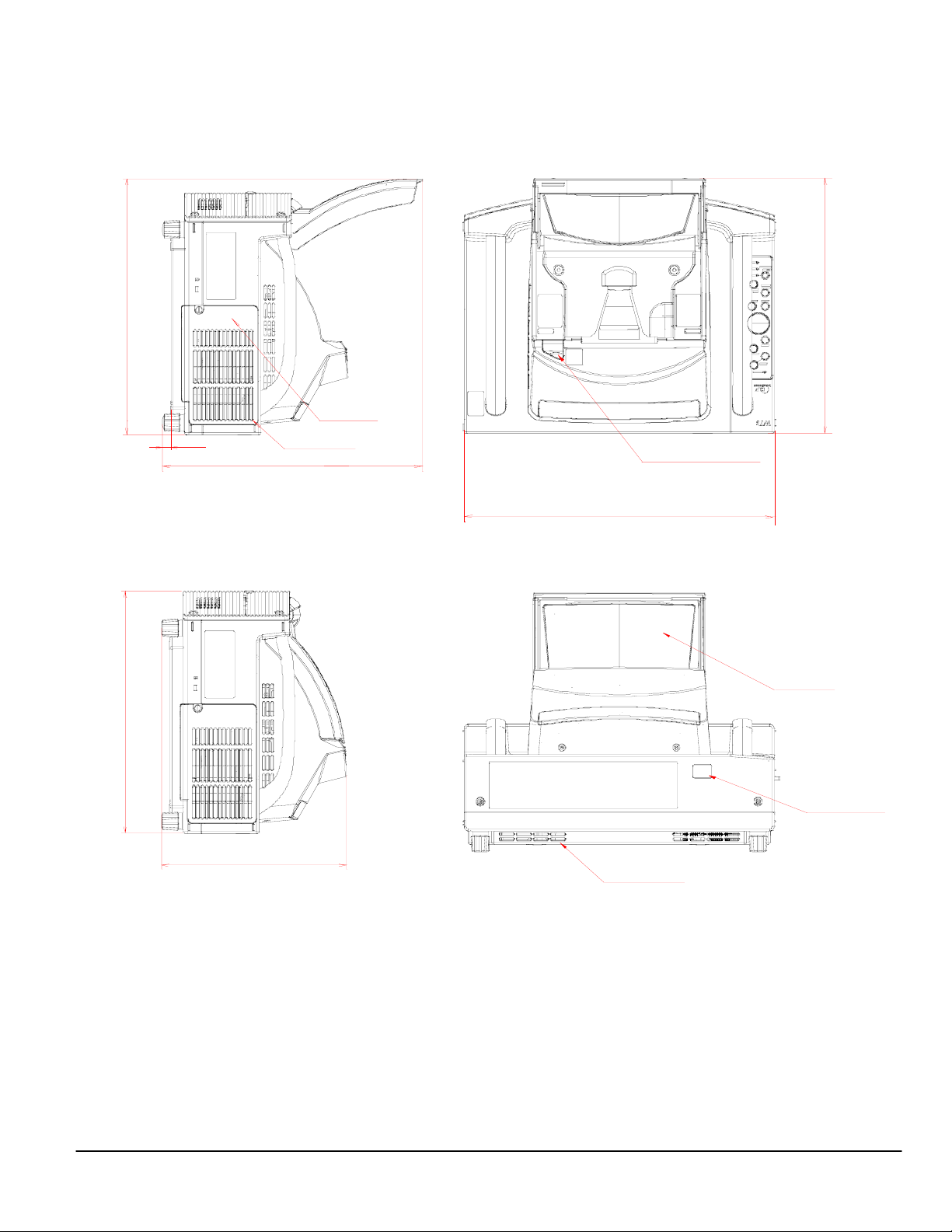
Cabinet Dimensions
The following drawings show the cabinet dimensions for the WT610.
Dimensions are in inches. For millimeters multiply by 25.4.
Mirrow cover open
12.32
11.85
0.378
mount standoff
Ventilation outlet
12.32
Mirrow cover closed
Lamp cover
12.32
10
Mirror cover lock switch
14.96
Final Mirror
8.84
Ventilation outlet
www.necvisualsystems.com WT610 Page 4 of 7
Remote Sensor
Page 5
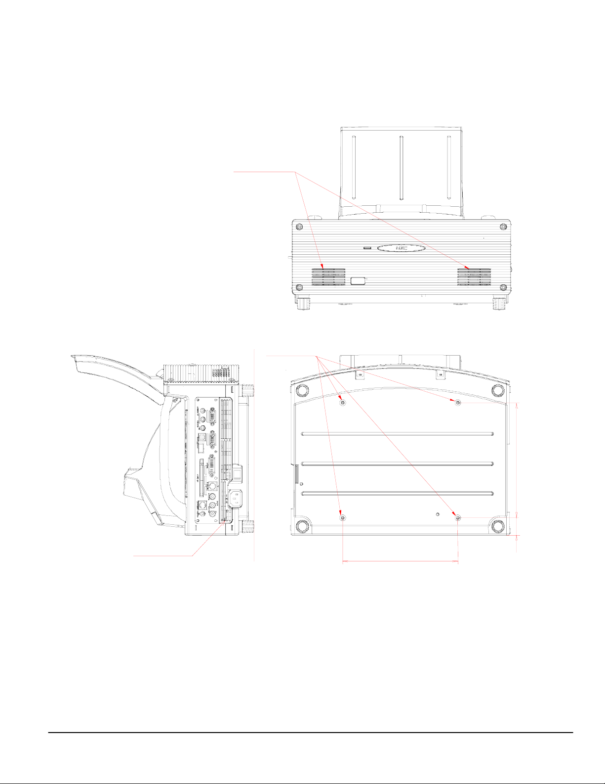
Cabinet Dimensions (continued)
The following drawings show the cabinet dimensions for the WT610.
Dimensions are in inches. For millimeters multiply by 25.4.
Speakers
M4*8 MAX
For Mount
7
8
.
7
8
1
Ventilation inlet
7.87
.
1
www.necvisualsystems.com WT610 Page 5 of 7
Page 6
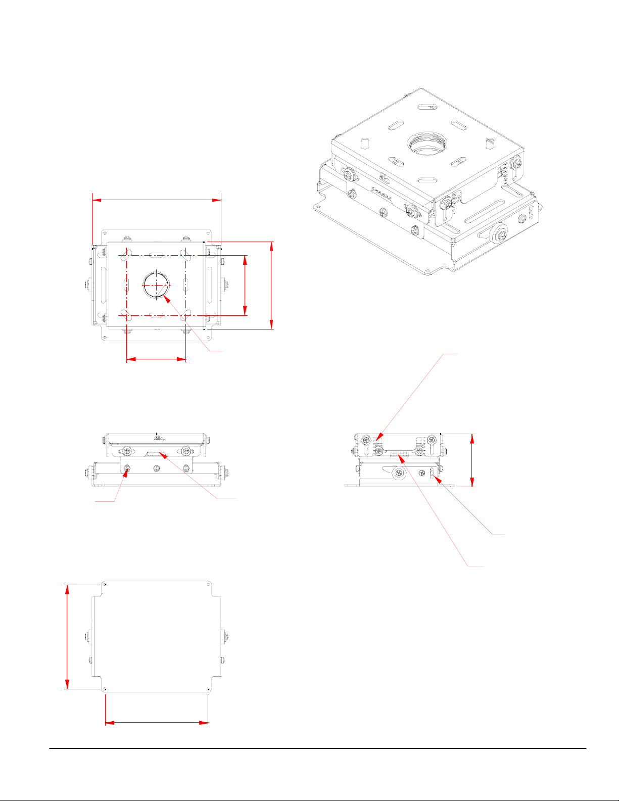
Optional Ceiling Mount Dimensions (Model #: WT60CM)
The following drawings show the ceiling mount dimensions for the WT 610.
Dimensions are in inches. For millimeters multiply by 25.4.
Roll
7.87
www.necvisualsystems.com WT610 Page 6 of 7
9.88
4.5
7.87
4.5
1.5" NPT
Flat blade
screw driver
adjustment
Left/Right
+/- 0.5"
6.60
Flat Blade
screw driver
Adjustment
Up/Down
+/- 0.5"
4.47
(+/- 0.5" adjustment)
Tilt
Flat blade
screw driver
adjustment
Forward/Back
+/- 0.5"
Page 7
Control Codes
Function Code Data
POWER ON 02H 00H 00H 00H 00H 02H
POWER OFF 02H 01H 00H 00H 00H 03H
INPUT SELECT RGB 02H 03H 00H 00H 02H 01H 01H 09H
INPUT SELECT DVI (ANALOG) 02H 03H 00H 00H 02H 01H 02H 0AH
INPUT SELECT DVI (DIGITAL) 02H 03H 00H 00H 02H 01H 1AH 22H
INPUT SELECT VIDEO 02H 03H 00H 00H 02H 01H 06H 0EH
INPUT SELECT S-VIDEO 02H 03H 00H 00H 02H 01H 0BH 13H
INPUT SELECT VIEWER 02H 03H 00H 00H 02H 01H 1FH 27H
PICTURE MUTE ON 02H 10H 00H 00H 00H 12H
PICTURE MUTE OFF 02H 11H 00H 00H 00H 13H
SOUND MUTE ON 02H 12H 00H 00H 00H 14H
SOUND MUTE OFF 02H 13H 00H 00H 00H 15H
ON SCREEN MUTE ON 02H 14H 00H 00H 00H 16H
ON SCREEN MUTE OFF 02H 15H 00H 00H 00H 17H
Note: Contact your NEC rep for codes not listed.
Cable Connection
Communication Protocol: PC Control Connector (DIN-8P)
Baud Rate: 38400 bps
Data Length: 8 bits
Parity: No Parity
Stop Bit: One bit
X on/off: None
Communications: Full duplex
To GND of PC
NOTE 1: It is recommended to set the projector to “Idle Mode” in the Setup menu for best Power ON response.
NOTE 2: Pins 2, 3, 5, 6 and 8 are used inside the projector.
NOTE 3: For long cable runs it is recommended to set communication speed in the Setup menu to 9600 bps.
To RxD of PC
678
345
12
To TxD of PC
www.necvisualsystems.com WT610 Page 7 of 7
 Loading...