

NEC versa 6060 schematic

SOLD BY laptopia2005 DO NOT RESELL!!
PROPRIETARY NOTICE AND LIABILITY DISCLAIMER
The info rmat ion disclos ed in t his do cument , inclu ding all designs and r elat ed materials, is
the valuable property of NEC Computer Systems Division, Packard Bell NEC, Inc.
(NECCSD, P BNEC) and/or its licensors. NECCSD and/o r its licensors, as appro priate, reserve all patent, copyright and other proprietary rights to this document, including all design, manufacturing, reproduction, use, and sales rights thereto, except t o the extent said
rights are expressly granted to others.
The NECCSD product(s) discussed in this document are warrant ed in accordance with the
terms of the Warranty Statement accompanying each product. However, actual
performance of each such product is dependent upon factor s such as system configuration,
customer data, and operator control. Since implementation by customers of each product
may vary, the suitability of specific product configurations and applications must be
determined by the customer and is not warranted by NECCSD.
To allow for design and specification impro vement s, t he information in this do cument is
subject to change at any time, without not ice. Reproduction of this document or port ions
thereof without prior written approval of NECCSD is prohibited.
FaxFlash is a ser vice ma rk of NEC Computer Systems Division (NEC CSD) , Packar d Bell NEC, In c.
NEC is a registered trademark, Versa is a U.S. registered trademark, MiniDock, VersaBay, VersaGlide, and
PortBar are trademarks, and UltraCare is a U.S. registered service mark of NEC Corporation, used
under license.
All other product, brand, or trade names used in this publication are the property of their respective owners
.
First Printing — September 1997
Copyright 1997
NEC Computer Systems Division, Packard Bell NEC, Inc.
1414 Massachusetts Avenue
Boxborough, MA 01719
All Rights Reserved
SOLD BY laptopia2005 DO NOT RESELL!!

SOLD BY laptopia2005 DO NOT RESELL!!
Preface
This service and reference manual contains the technical info r mation necessary to set up and
maintain the NEC Ve rs a® 6060 notebook computer.
The manual also pro vides hardware and interface information for users who need an overview of the system design. T he manual is written for NEC-t r ained customer engineers, system analysts, service center personnel, and dealers.
The manual is organized as follows:
Section 1 Technical Information, pr ovides an overview of the har dwar e and interface
components. System specifications are listed including computer dimensio ns, weight, environment, safety compliance, power consumption, and system memory specifications.
Section 2 Setup and Operation, takes t he aut ho r ized service technician or dealer from
unpacking to setup and o per ation. The section includes a description of operating controls,
setting parameters and accessing the NECCSD bulletin board system (BBS).
xi
Section 3 Troubleshooting, lists troubleshooting procedures as well as helpful
se rvicing hints.
Section 4 Field Service Guidelines, provides disassembly and assembly procedures,
and an explo ded- view diagram of the NEC Versa system with part number s.
Appendix A Connector Locations and Pin Assignments, pro vides a list of the main
board internal connector pin assignments and a list of external pin assignments.
Appendix B Video Modes, lists NEC Versa supported video modes.
An Index is included for convenience.
SOLD BY laptopia2005 DO NOT RESELL!!

SOLD BY laptopia2005 DO NOT RESELL!!
Abbreviations
xiii
Aampere
AC alternating current
ACPI advanced control power
interface
APM advanced power management
AT advanced technology
(IBM PC)
BBS Bulletin Board System
BCD binary-code d dec imal
BC U BIOS Customiz ed Utility
BIOS basic input/out put system
bit binary digit
bp i bits per inch
bps bits pe r second
BUD BIOS Upgrade Diskette
C Celsius or centigrade
Cache high-speed buffer storage
CAM constant ly addressable memory
CAS column address stro be
DC direct current
DIMM dua l-inlin e memory mod ule
DIP dual in -line p acka ge
DLAB Divisor Latch Add ress bit
DMA direct memory access
DMAC DMA controller
DOS disk operating system
DRAM dynamic RAM
DTE data ter minal equipment
ECC error checking and correction
ECP extended capabilities port
EDO enhance d date out
EDS error detecting system
EGA E nhanced Graphics Adapter
EMS E xpanded Memory
Specification
EPP enhan ced p ar alle l por t
EPROM erasable and pr ogrammable
ROM
CCFT co ld cathode
CD-ROM compact disk ROM
CGA Color Graphics Adapter
CGB Color Graphics Board
CH channel
clk clock
cm cen timeter
CM OS comp leme nt ar y metal ox ide
semiconducto r
codec compressor/decompressor
COM communication
CONT contrast
CPGA cer amic pin grid a rray
CPU central processing unit
CRT c athode-ra y tube
DAC digital-to-analog convert er
DACK DMA acknowledge
EVGA E nhanced Video Graphics
Array
F Fahrenheit
FAX facsimile tra nsmis sion
FCC Federal Communications
Commission
FDD flo ppy disk drive
FG frame ground
FIR fast infrared
FM frequency modulation
Fn function
FP U f loating -po int un it
FRU field-replaceable unit
GB gigabyte
GND ground
GUI graphical user interface
HDD hard disk drive
SOLD BY laptopia2005 DO NOT RESELL!!

SOLD BY laptopia2005 DO NOT RESELL!!
xiv Abbreviations
HEX hexadecimal
HGA Hercules Graphics Adapt er
Hz hertz
IC integrated circuit
ID identification
IDE inte lligent devic e elec tronics
IDTR interrupt descriptor table
register
IMR Interrupt Mask register
in. inch
INTA interrupt acknowledge
IPB illus tra ted parts breakd own
IR infrared
IRR Interrupt Request register
ISA Industry Standard Architecture
ISR In Service register
I/O input/output
IPC integrated peripheral controller
ips inches pe r sec ond
IRQ interrupt request
K kilo (1024)
k kilo (1000)
KB kilobyte
kg kilogram
kHz kilohertz
kV kilovolt
lb pound
LCD liquid crystal display
LDTR local descriptor t able register
LED light-emitting diode
LSB least- significant bit
LSI large-scale integration
Mmega
mA milliamps
max maximum
MB megabyte
MDA Monochrome Display Adapter
MFM modified frequency mo dulation
Mhz megahertz
mm millimeter
ms millisecond
MSB most-significant bit
NASC National Authorized Service
Center
NC not co nnected
NDP numeric dat a pr ocessor
NMI Non-maskable Interrupt
ns nanosecond
NSRC National S er vice Response
Center
NTFS NT file allocation
PAL programmable array logic
PC per sonal computer
PCB pr inted circuit board
PCI pe riphe ra l compon ent
interconnect
PFP plastic flat package
PIO parallel input/output
pixel picture element
PJQFP plastic J-lead quad flat pack
PLCC plastic lead chip carr ier
PLL phas e lock loop
p-p peak-to-peak
PnP Plug and Play
PPI programmable peripheral
interface
PROM prog ra mmable ROM
QFP quad flat pack
RAM random-access memory
RAMDAC RAM digital-to-analog
RAS row ad d r ess strobe
RGB r ed gr een blue
RGBI red green blue intensity
ROM re ad -only memor y
rpm revolutions per minute
SOLD BY laptopia2005 DO NOT RESELL!!

SOLD BY laptopia2005 DO NOT RESELL!!
R read
RTC real-time clo ck
R/W read/write
Sslave
SCSI Small Computer System
Interface
SDLC Synchronous Data Link
Contr o l
SG signal gr ound
SIMM single inline memory module
SIR seria l infrar ed
SOIC small outline integrated circuit
SQFP silver quad flat package
Abbreviations xv
SVGA Super Video Graphics Array
SW switch
TCP thin chip package
TFT th in film t ransisto r
TQFP thin-quad flat package
TSC Technical Support Center
TTL transistor/transistor log ic
tpi tracks per inch
UART universal asynchronous
receiver/transmitter
USB U niversal Se rial Bus
Vvolt
Vdc volts, direct current
VESA Video Electronics Standards
Association
VFO variable fr equency oscillator
VGA Video Graphics Array
VLSI ver y large-scale int egr ation
VRAM virtual RAM
Wwatt
µf microfarad
µPD microprocessor
µs microsecond
Ω ohm
SOLD BY laptopia2005 DO NOT RESELL!!

SOLD BY laptopia2005 DO NOT RESELL!!
Contents
Preface......................................................................................................................... xi
Abbreviation................................................................................................................ xiii
Section 1 Technical Information
Hardware Overview—Front.........................................................................................1-2
Liquid Crystal Display (LCD)................................................................................1-2
Power Button .......................................................................................................1-3
LCD Status Bar and Power Indicator....................................................................1-4
Status Icons ...................................................................................................1-5
Keyboard..............................................................................................................1-5
NEC VersaGlide...................................................................................................1-6
iii
Diskette Drive and the NEC VersaBay II ..............................................................1-7
Infrared (IR) Assembly..........................................................................................1-7
Hardware Overview—Right Side.................................................................................1-8
Hardware Overview—Left Side...................................................................................1-9
PC Card Slots.......................................................................................................1-9
Battery Bay Cover Release....................................................................................1-9
Hardware Overview—Rear Side..................................................................................1-10
Keyboard/Mouse Port...........................................................................................1-10
Parallel Port (LPT1)..............................................................................................1-10
Expansion Port ..................................................................................................... 1-11
External Monitor (Video) Port..............................................................................1-11
Serial Port (COM1) ..............................................................................................1-11
Hardware Overview—Internal Components.................................................................1-11
Battery Pack.........................................................................................................1-11
Hard Disk Drive....................................................................................................1-11
Diskette Drive.......................................................................................................1-12
Versa Bay II SuperDisk LS-120 Drive ..................................................................1-12
20X CD-ROM Reader ..........................................................................................1-12
CPU Board...........................................................................................................1-12
Audio Board.........................................................................................................1-13
AMP Board..........................................................................................................1-14
I/O Board.............................................................................................................1-14
CMOS Battery......................................................................................................1-14
Bridge Battery......................................................................................................1-14
SOLD BY laptopia2005 DO NOT RESELL!!

SOLD BY laptopia2005 DO NOT RESELL!!
iv Contents
System Memory...........................................................................................................1-14
Memory Map........................................................................................................1-14
System Video...............................................................................................................1-15
Parallel Interface..........................................................................................................1-15
Serial Interface.............................................................................................................1-16
NEC Versa Chip Set....................................................................................................1-16
Intel Pentium P55CLM Microprocessor................................................................1-17
M-Trit o n System Controllers ................................................................................1-17
256K X Flash ROM..............................................................................................1-17
ROM BIOS....................................................................................................1-17
VGA Controller....................................................................................................1-18
Parallel Interface ...................................................................................................1-18
Keyboard Cont ro ller .............................................................................................1-18
PC CardBus Controller.........................................................................................1-19
Sound Integrated Circuit.......................................................................................1-19
Interrupt Controllers.............................................................................................1-20
Power Management Overview .....................................................................................1-21
System Power Management ..................................................................................1-22
Local Power Management.....................................................................................1-22
Plug and Play...............................................................................................................1-23
Specifications............................................................................................................... 1-24
Section 2 Setup and Operation
Unpacking t he Syst em..................................................................................................2-1
Hardware Setup...........................................................................................................2-1
Cable Connections................................................................................................2-3
Power Sources.............................................................................................................2-4
Using the AC Adapter...........................................................................................2-4
Using the Main Battery Pack.................................................................................2-5
Checking Battery Power Levels......................................................................2-5
What t o Do When Battery Power Get s Low...................................................2-5
Returning the Battery to Full Operation..........................................................2-6
When to Change the Battery..........................................................................2-6
Battery Handling............................................................................................2-6
Replacing the Battery Pack ............................................................................2-7
Batter y Precaut ions........................................................................................ 2-10
Recharging Battery Precautions...................................................................... 2-10
SOLD BY laptopia2005 DO NOT RESELL!!

SOLD BY laptopia2005 DO NOT RESELL!!
NEC VersaBay II Batt ery and Adapt er Kit (Optional)...........................................2-11
Extending Batt ery Life..........................................................................................2-11
Using the DC Car Adapter....................................................................................2-11
Operating Controls ...................................................................................................... 2-12
Status Bar.............................................................................................................2-13
Status Icons ...................................................................................................2-13
Function Keys (Fn Keys).......................................................................................2-14
Smart Po wer Switch.............................................................................................2-14
Dip Switch............................................................................................................2-15
Updating the System BIOS ............................................................................2-15
Customizing BIOS Message...........................................................................2-17
Power-on Self-Test (POST).........................................................................................2-17
POST Errors.........................................................................................................2-18
Contents v
Setup Utility ................................................................................................................ 2-19
Accessing Setup ....................................................................................................2-20
With an Error at POST ..................................................................................2-20
With No Errors at POST................................................................................2-20
Setup U tility Main Menu....................................................................................... 2-20
How to Use Setup..........................................................................................2-21
Looking at Screens ........................................................................................2-21
Using Keys.....................................................................................................2-22
Checking/Setting System Parameters..............................................................2-22
Setup Menus.........................................................................................................2-25
Standard CMOS Setup...................................................................................2-27
Advanced CMOS Setup.................................................................................2-26
Power Management Setup Po wer Management Setup....................................2-26
Peripherals Setup ...........................................................................................2-28
Change User Password...................................................................................2-28
Change Supervisor.........................................................................................2-28
Auto Configuration with Default s...................................................................2-28
Save Setting and Exit.....................................................................................2-28
Exit Without Saving.......................................................................................2-29
Using Setup to Set Power Management ................................................................2-29
Using the Save to File (STF) Feature..............................................................2-29
STF Benefits..................................................................................................2-30
Automatic Power-Saving Features........................................................................2-31
SOLD BY laptopia2005 DO NOT RESELL!!

SOLD BY laptopia2005 DO NOT RESELL!!
vi Contents
Section 3 Troubleshooting
Quick Troublesho o t ing ................................................................................................3-1
Helpful Questions ........................................................................................................3-4
Section 4 Field Service Guidelines
Preventive Maintenance...............................................................................................4-1
Cleaning the Notebook’s Exterior.........................................................................4-1
Cleaning the Notebook’s Interior..........................................................................4-2
Protecting the Disk Drives ....................................................................................4-2
Handling the Battery Packs...................................................................................4-3
Maintaining the LCD Quality................................................................................4-3
Required Tools and Equipment....................................................................................4-3
Disassembly and Reassembly........................................................................................4-4
Hard Disk Drive....................................................................................................4-5
Diskette Drive.......................................................................................................4-7
Main Battery Pack (Li-Io n Type) ..........................................................................4-8
LCD and Top Cover.............................................................................................4-10
Power Button, Microphone Assembly, Keyboard..................................................4-12
LCD Status Bar, VersaGlide Assembly, Metal Keyboard Supports........................4-14
Bridge Battery, CMOS Battery, Buzzer ................................................................4-15
CPU Board...........................................................................................................4-16
AMP Board..........................................................................................................4-17
I/O Board.............................................................................................................4-17
Illustrated Parts Breakdown.........................................................................................4-18
Service Informatio n......................................................................................................4-22
Technical Support........................................................................................................4-22
Product Informatio n .....................................................................................................4-23
Ordering Informatio n from FaxFlash............................................................................4-24
Appendix A Connector Locations and Pin Assignme nts
Appendix B Video Modes
Index
SOLD BY laptopia2005 DO NOT RESELL!!

SOLD BY laptopia2005 DO NOT RESELL!!
List of Figures
1-1 NEC Versa 6060 Notebook ........................................................................... 1-1
1-2 LCD Panel..................................................................................................... 1-3
1-3 Power Button Locat ion.................................................................................. 1-4
1-4 System Status Bar.......................................................................................... 1-4
1-5 Keyboard Layout........................................................................................... 1-6
1-6 VersaGlide Location ...................................................................................... 1-6
1-7 NEC VersaBay II Location............................................................................ 1-7
1-8 Right Side Features ........................................................................................ 1-8
1-9 Left Side Features.......................................................................................... 1-9
1-10 Rear Features ................................................................................................. 1-10
1-11 CPU Board Layout ........................................................................................ 1-12
1-12 Audio Board Layout ...................................................................................... 1-13
Contents vii
2-1 Connecting the AC Adapter ........................................................................... 2-1
2-2 Powering on the System................................................................................. 2-2
2-3 Power and I/O Connector Locatio ns .............................................................. 2-3
2-4 NEC Versa AC Adapter ................................................................................. 2-4
2-5 Removing the Cover ...................................................................................... 2-8
2-6 Removing the Battery.................................................................................... 2-8
2-7 Inserting t he Battery Pack.............................................................................. 2-9
2-8 Replacing the Co ver....................................................................................... 2-9
2-9 Connecting the Car DC Adapter..................................................................... 2-11
2-10 Keyboard Panel LEDs and Controls............................................................... 2-12
2-11 Status Bar Location ....................................................................................... 2-13
2-12 Dip Switch Location...................................................................................... 2-16
2-13 Setup Main Menu........................................................................................... 2-21
2-14 Advanced CMOS Setup Menu ....................................................................... 2-22
4-1 Removing the Drive Bay Cover...................................................................... 4-5
4-2 Removing the Hard Disk Drive ...................................................................... 4-6
4-3 VersaBay II Release Latches.......................................................................... 4-7
4-4 Removing the Standard Diskette Drive........................................................... 4-8
4-5 Removing the Battery Compart ment Cover.................................................... 4-9
4-6 Removing the Battery.................................................................................... 4-9
4-7 Removing the Bottom Base Screws................................................................ 4-10
4-8 Disconnecting the LCD Connectors ............................................................... 4-11
SOLD BY laptopia2005 DO NOT RESELL!!

SOLD BY laptopia2005 DO NOT RESELL!!
viii Contents
4-9 Removing the Power Butt o n, Microphone Assembly, Keyboard..................... 4-12
4-10 Disconnecting Keyboard Cables..................................................................... 4-13
4-11 LCD Status Bar, VersaGlide Assembly, Metal Keybo ard Supports................. 4-14
4-12 Br idge Battery, CMOS Batter y, Buzzer ......................................................... 4-15
4-13 Removing the CPU Board.............................................................................. 4-16
4-14 Removing the I/O Board................................................................................ 4-18
4-15 NEC Versa Model 6060 Illustrated Parts Breakdown..................................... 4-26
A-1 CPU Board Layo ut ........................................................................................ A-1
A-2 I/O Board Layout........................................................................................... A-2
List of Tables
1-1 Model Configurations .................................................................................... 1-2
1-2 Memory Map................................................................................................. 1-15
1-3 NEC Versa Series Chip Types and Technologies............................................ 1-16
1-4 Int errupt Controllers ...................................................................................... 1-20
1-5 Auto matic Po wer-Saving Features ................................................................. 1-21
1-6 Maximum Performance Default Set t ings......................................................... 1-23
1-7 Specifications................................................................................................. 1-24
2-1 I/O Connector Descriptions............................................................................ 2-3
2-2 Cont rol and Switch Functions........................................................................ 2-12
2-3 Fn Key Operations ......................................................................................... 2-14
2-4 POST Error Messages.................................................................................... 2-18
2-5 Setup Key Functions ...................................................................................... 2-22
2-6 Setup Parameters........................................................................................... 2-22
3-1 Quick Troubleshooting................................................................................... 3-1
4-1 NEC Versa 6060 Series Disassembly Sequence.............................................. 4-4
4-2 NEC Versa 6060 Series Field-Replaceable Parts............................................. 4-20
4-3 NEC Service and Informatio n Telephone Numbers......................................... 4-22
A-1 CPU Board Connectors.................................................................................. A-2
A-2 I/O Board Connectors.................................................................................... A-2
A-3 Keyboard/Mouse Connectors......................................................................... A-3
A-4 Serial Port Connect o r Pin Assignments .......................................................... A-3
SOLD BY laptopia2005 DO NOT RESELL!!

SOLD BY laptopia2005 DO NOT RESELL!!
A-5 CRT Connector Pin Assignment s ................................................................... A-4
A-6 Parallel Printer Pin Assignments ..................................................................... A-4
A-7 Power Connector ........................................................................................... A-5
A-8 Hard Disk Drive Connect o r............................................................................ A-5
B-1 LCD Display Mode Setting (800x600 TFT Color LCD and
Simultaneous CRT Display) ....................................................................... B-1
B-2 LCD Display Extended Video Mode.............................................................. B-2
B-3 CRT Display Mode (CRT only)...................................................................... B-3
B-4 CRT Display Extended Video Mode .............................................................. B-4
B-5 Panning Video Mode (800x 600 TFT Color LCD and
Simultaneous CRT Display) ....................................................................... B-4
Contents ix
SOLD BY laptopia2005 DO NOT RESELL!!
SOLD BY laptopia2005 DO NOT RESELL!!
Section 1
Technical Information
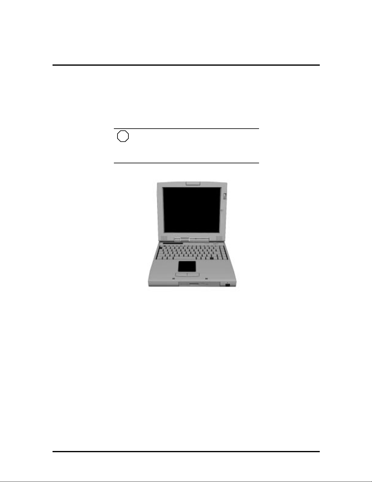
The NEC Versa 6060 notebook computer is lightweight, compact, and fully IBM compatible. This is the latest addition to the NEC Vers a family.
NOTE
This service manual covers only the NEC
Versa 6060 model. All figures in t his manual reflect th is model.
Figure 1-1 NEC Versa 6060 Notebook
This section of the manual provides system configuration information, including an overview of hard war e and interface components. See the following table for a systems specific
brea kdo wn of hardware.
SOLD BY laptopia2005 DO NOT RESELL!!
SOLD BY laptopia2005 DO NOT RESELL!!
1-2 Technical Information
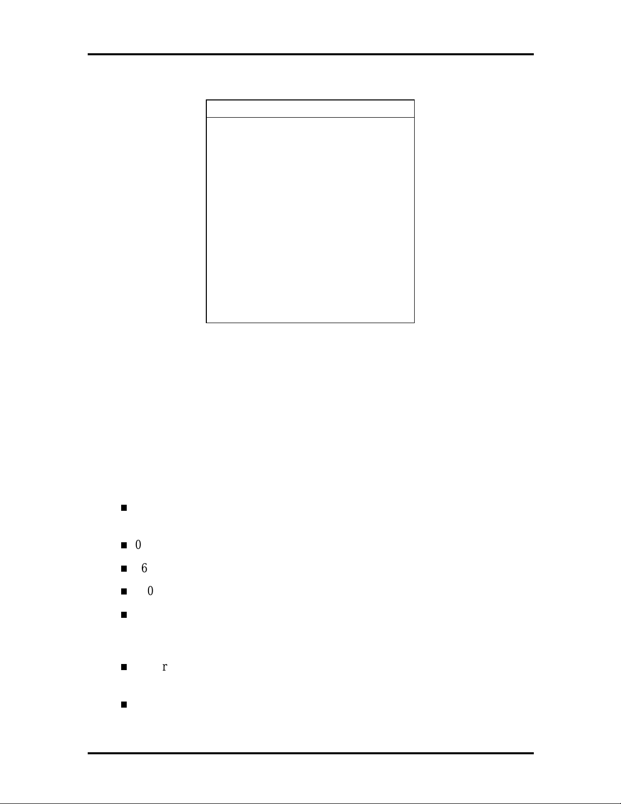
Table 1-1 Model Configurations
FEATURE NEC Versa 6060
CPU Intel Pentium® with
On-Boar d DRA M 16-MB
Video M emory 2-MB incl uded in
Hard Disk Driv e 2.1 GB or 3.2 GB
CD-ROM Reader 20X CD ROM Reader
MMX Technology
P55CLM/166 MHz
video chip
FDD or
SuperDisk LS-120
Color LCD 12.1” CCFT S uper
3 ½” 1.44M B
120MB
VGA(SVGA),TFT
Color Display
HARDWARE OVERVIEW—FRONT
Take a moment to be come familiar w ith th e locatio n and fu nction of co nt rols located on th e
front of the system.
Liquid Crystal Display (LCD)
The LCD operates with NeoMagic NMG4 VGA controller. The controller supports XGA,
uses a 64-bit accelerator with a Peripheral Component Interco nnect ( P CI ) interface.
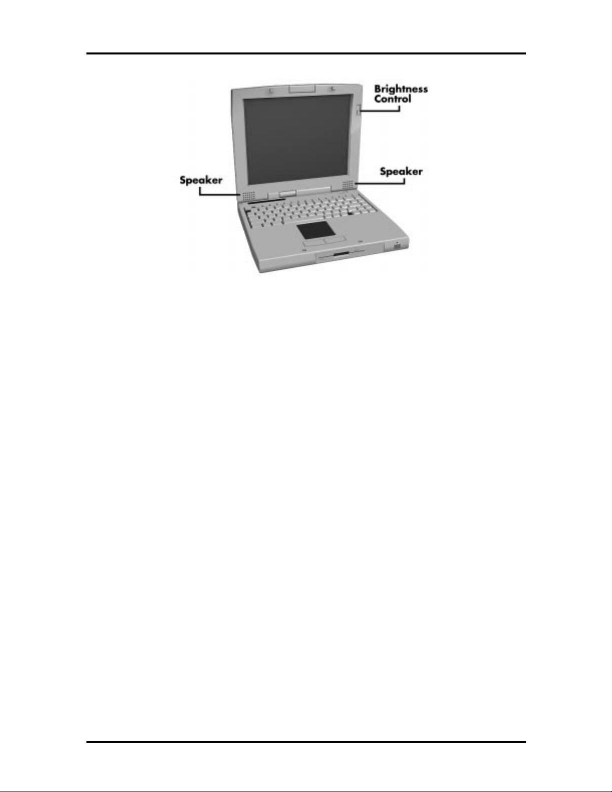
The NEC Versa 6060 LCD features the following:
12. 1-inch Thin Film Tran sistor ( TFT) CCFT S up er VG A (SVGA) sin gle -backlite
color
0.306 mm dot pitch
16-bit digital interface
800 x 600 resolution
64K colors.
Additional LCD panel features:
Power LED that indicates the current power status. This LED is visible with the
LCD panel opened or closed.
Slide swit ch that adjusts screen brightness.
SOLD BY laptopia2005 DO NOT RESELL!!
SOLD BY laptopia2005 DO NOT RESELL!!
Figure 1-2 LCD Panel
Technical Information 1-3
Another video feature includes a CRT port o n t he system's rear panel that allows the user to
connect an opt ional monochrome or color external display to the system. The computer can
support the LCD and external display simultaneously.
Power- sav ing features for con trolling t he L CD's backlig ht ing in clude th e ROM-based h ot
key comb ination
and Operation, for information on using these sett ings. In addition, the automatic LCD
status featur e conserves the backlight. When the LCD is closed the backlight shuts off
automatically, saving battery power.
, and Auto Setup po wer management settings. See Section 2, Setup
Fn F5
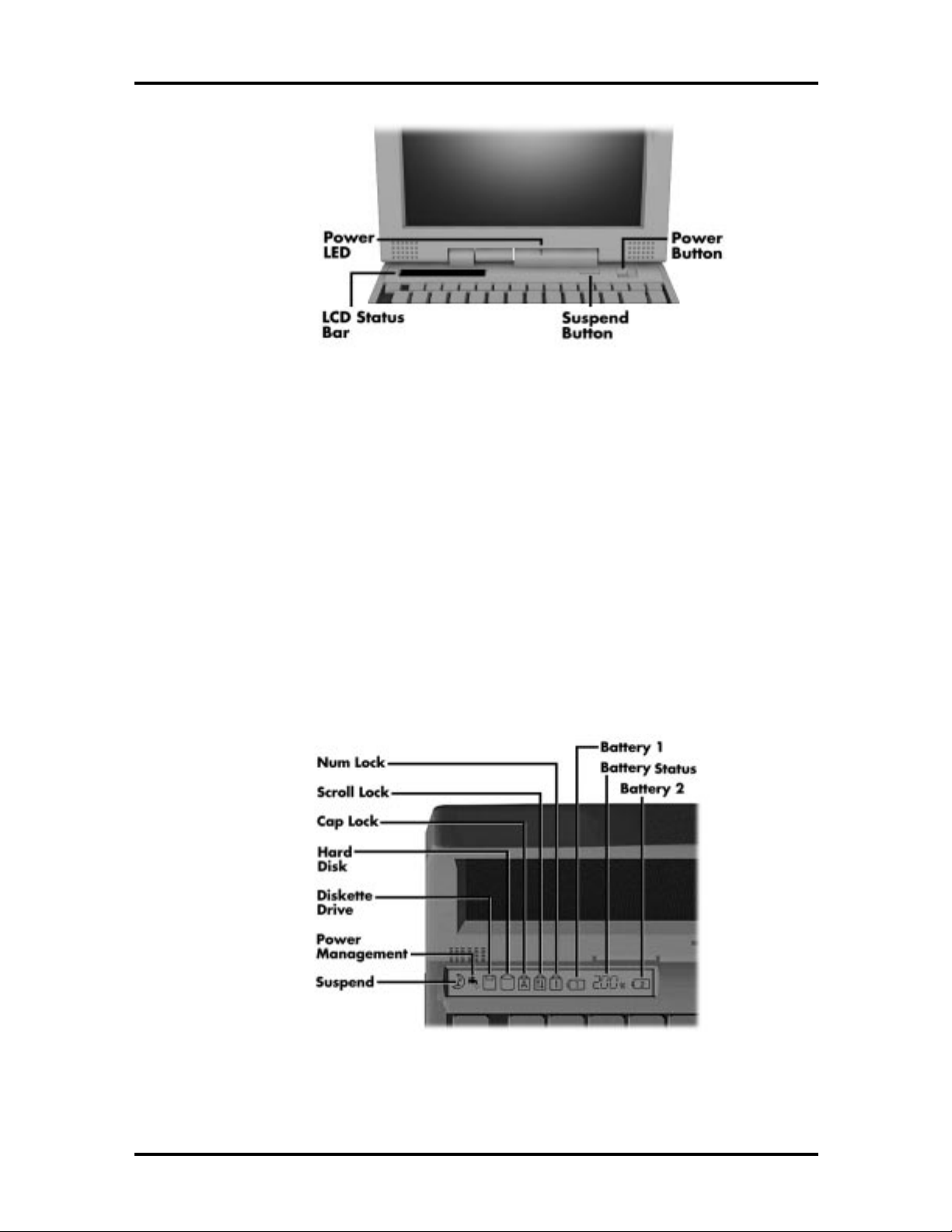
Power Button
Slide the Power button to the right to power on and power off the computer. The Power
butto n is a “smar t” switch, meaning that it recognizes when the system is in Suspend mode.
If in Suspend mode, you cannot power off until yo u pr ess the Suspend butto n again to bring
the system out of Suspend mode.
SOLD BY laptopia2005 DO NOT RESELL!!
SOLD BY laptopia2005 DO NOT RESELL!!
1-4 Technical Information
Figure 1-3 Pow er Button Location
LCD Status Bar and Power Indicator
The LCD status bar is situated right below the LCD screen. It pro vides an easy way to detect system stat us. Different graphic icons appear on the LCD bar indicating that a device is
accessed, an operat ion performed, or a po wer mode activated. The graphic icons displayed
on the LCD bar resemble either t heir physical characteristics or their primary function. See
the LCD Stat us Bar figure shown next, and the descriptions that follow for the specific
meaning of each icon.
The power indicator is located just above and to t he right of the stat us bar. T he po wer indicator lights green when computer power is on, blinks green when in Suspend mode and
blinks amber to indicate that t he batt er y power is low.
Figure 1-4 System Status Bar
SOLD BY laptopia2005 DO NOT RESELL!!

SOLD BY laptopia2005 DO NOT RESELL!!
Status Icons
The following list defines the status icons displayed in the system status bar.
Suspend — appears when the system is in Suspend mode. Suspend mode con-
serves system power by shutting down devices in the system while ret aining data
and system status.
Power Management — shows the current power management mode in use, in-
cluding Off, Custom, High Performance or Longest Life.
Diskett e or Versa Bay II SuperDisk LS-120 drive — appears when the NEC
Versa writes data to or retrieves data from a diskette.
Hard Disk — shows when the NEC Versa writes data to or retrieves data from
the hard disk.
Caps Lock — appears when Caps Lock is in effect.
Technical Information 1-5
Scroll Lo ck — sh ows th at Scr oll Lo ck is in e ffect.
Num Lock — appears when Num Lock is in effect. Num Lock lets the user enter
number s for calculations via the numeric keyp ad.
Battery Status — displays the total percentage of battery power available.
Battery 1 appears when you have the main battery installed in the battery bay.
Batter y 2 appears when you have an optional battery installed in the
VersaBay II.
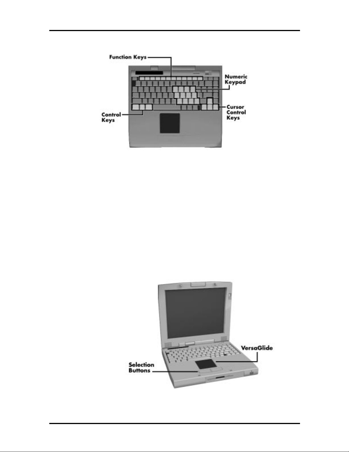
Keyboard
The built-in, 83-key keyboard (U.S.) or 79-key keyboard (UK and Germany) uses the standard QWERTY format. The keyboard pro vides 12 function keys and 7 cursor control keys,
with an Fn key for ROM-based key functions. The numeric keypad is embedded in the standard key layout.
SOLD BY laptopia2005 DO NOT RESELL!!
SOLD BY laptopia2005 DO NOT RESELL!!
1-6 Technical Information
Figure 1-5 Keyboard Layout
NEC VersaGlide
The NEC VersaGlide is a built-in mechanism that functions as the system’s mouse. It co ntro ls the on-screen po inter (cur sor). T o use the VersaGlide, move your finger across the
NEC VersaGlide pad, and the cursor follows. T he buttons below the NEC VersaGlide allow the user to select or deselect menu items. Tap and double- tap are supported on the
VersaGlide pad.
If an external mouse is installed, the NEC VersaGlid e is deactivated. A serial mouse is not
supported.
Figure 1-6 VersaGlide Location
SOLD BY laptopia2005 DO NOT RESELL!!
SOLD BY laptopia2005 DO NOT RESELL!!
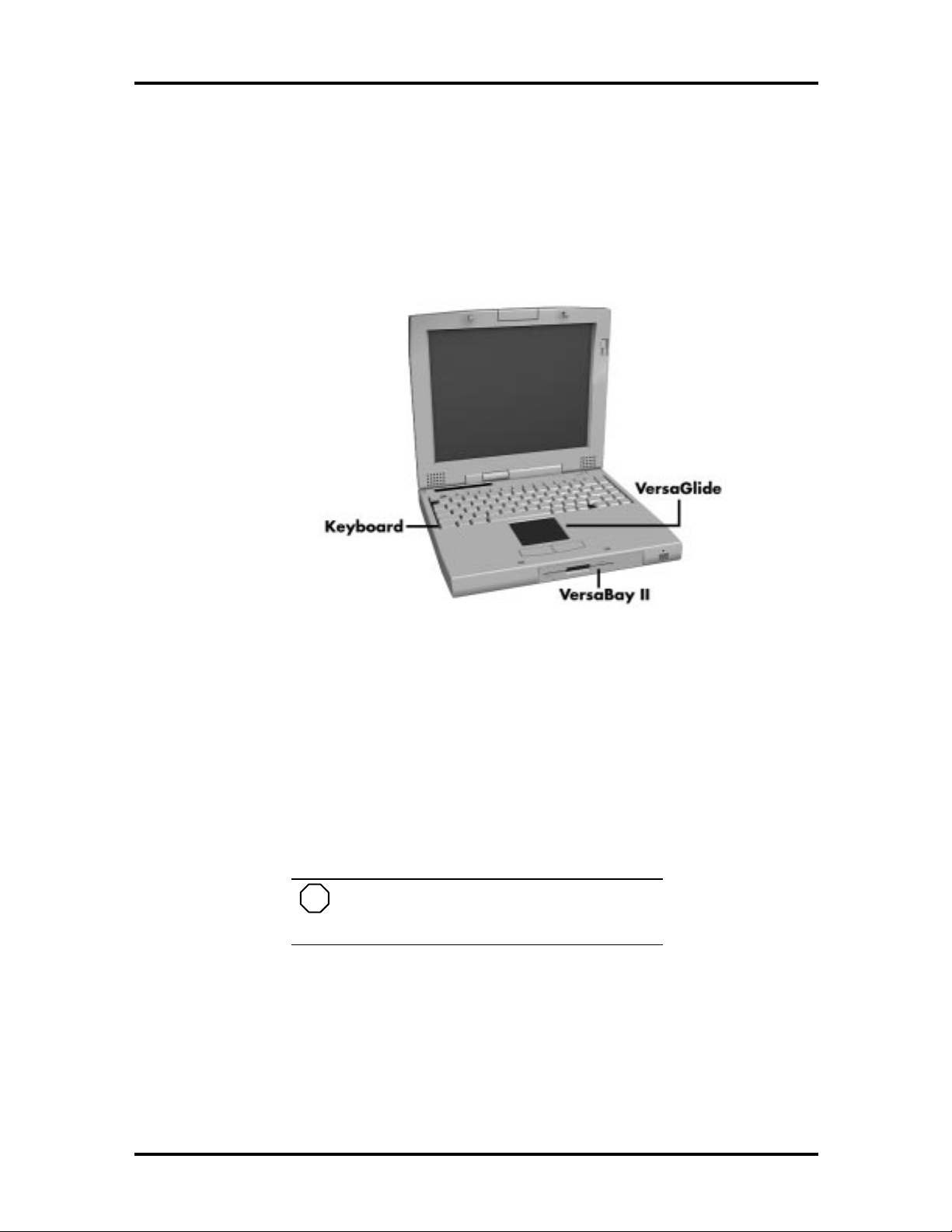
Diskette Drive, CD-ROM Reader and the NEC VersaBay II
A standard 1.44-MB diskette drive or Versa Bay II SuperDisk LS-120 drive come s installed in the VersaBay II slot o n t he front of the computer. The VersaBay II expansion slo t
lets the user replace the standard diskette drive with the 20X CD-ROM reader that also
ships wit h t he system. In addition to the CD-ROM reader, the VersaBay II accepts NEC
options including a second battery pack, or an additional har d disk.
Technical Information 1-7
Figure 1-7 NEC VersaBay II Location
Infrared (IR) Assembly
The IR assembly consists of a small board with one infrared LED and one pin photo diode,
attached t o the CPU board. T he board allows the NEC Versa computer to co mmunicate
with other infrar ed- r eady computers. Fo r example, the infrared po r t allows the user t o
transfer files between the NEC Versa and an IR-equipped computer, or print to an IRequipped printer without using cables.
NOTE
Do not use the IR port directly under fluorescent or incandescent light.
SOLD BY laptopia2005 DO NOT RESELL!!
SOLD BY laptopia2005 DO NOT RESELL!!
1-8 Technical Information
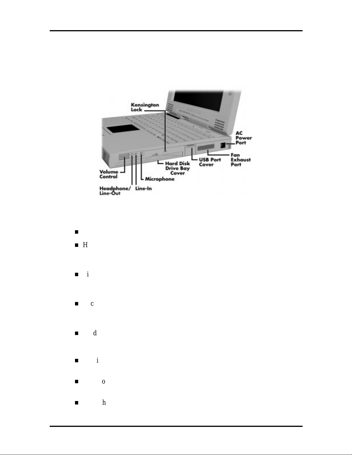
HARDWARE OVERVIEW—RIGHT SIDE
Review the following section for a description of the hardware on the right side of the NEC
Versa.
Figure 1-8 Right S i de Features
Volume Co nt rol — Allo ws you to control the speaker vo lume .
Headphones/Line- Out — Lets you connect external headphones, speakers or
audio system to your NEC Versa system. Using this port disables the built-in
system speakers.
Line-In — Lets you use another audio system, like a home ster eo, as an input
source. Use a the cable to connect to the Line-Out por t on the o ther audio system to record or play.
Microphone (MIC) — Allows you to connect an external microphone for
monophonic r ecording or amplification through the unit. Plugging in an ext ernal
microph on e d isables the built-in microphone .
Har d Disk Drive Bay Cover — The hard disk drive bay contains the r e movable
hard disk drive. Depending on yo ur NE C Ver sa’s configuration, it contains a
2.1-GB hard disk drive or 3. 2- GB hard disk drive.
Kensington L ock Connection — Lets you provide adde d security by ins talling
an optional Kensington Lock.
USB Port — The Universal Serial Bus (US B) allows the connection of up to
127 peripheral devices (printers, monitors, scanners, etc.) to your NE C Versa.
Fan Exhaust Port — This port provides air flow from the interior of the computer t o assist in keeping the system running at optimal per for mance.
SOLD BY laptopia2005 DO NOT RESELL!!
SOLD BY laptopia2005 DO NOT RESELL!!
!
Always keep the fan vents clear to allow proper
system cooling.
AC Power Por t — Use the power jack to attach the NEC Versa to a DC power
source, such as t he AC adapter or the op tional DC car adapter.
HARDWARE OVERVIEW—LEFT SIDE
Review the following section for a description of the hardware on the left side of the NEC
Versa.
Technical Information 1-9
CA UT ION
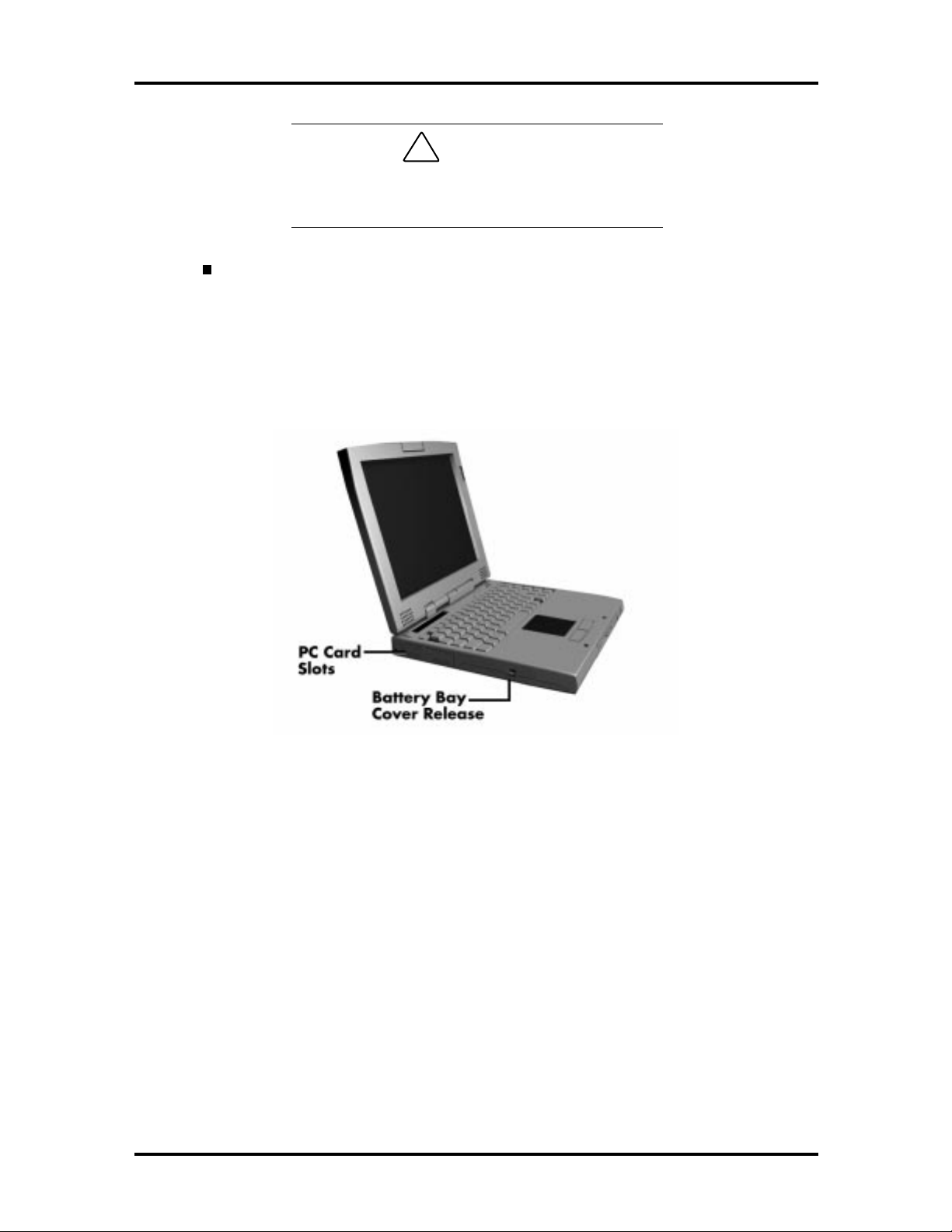
Figure 1-9 Left Side Features
PC Card Slots
The PC card slot compartment houses two Type II devices, or one Type III device. For
Type III cards, insert the PC card int o t he lower slot. Insert the card with the pin sockets
facing t owards the drive and the label facing up. To remove the PC card, push on the eject
butto n t o release the pin connections and slowly pull out the card.
Battery Bay Cover Release
The battery compartment houses the rechargeable Lithium Ion (Li-Ion) battery pack. The
battery pack instantly start t o charge whenever you connect the AC adapter to t he notebook. It is very important to always have the battery installed in the notebook to insure that
it is con tin uou sly ch arged. If the batte ry pack is un insta lled for a lon g p er iod of time, the
battery cells are dr ained, causing the battery pack to deter iorate.
SOLD BY laptopia2005 DO NOT RESELL!!
SOLD BY laptopia2005 DO NOT RESELL!!
1-10 Technical Information
The ba ttery bay cont a ins a n eight-cell Lithium Ion (L i- Ion) batte ry that lets you run your
system on DC power.
HARDWARE OVERVIEW—REAR SIDE
Review the following section for a description of the hardware on the rear of the NEC
Versa.
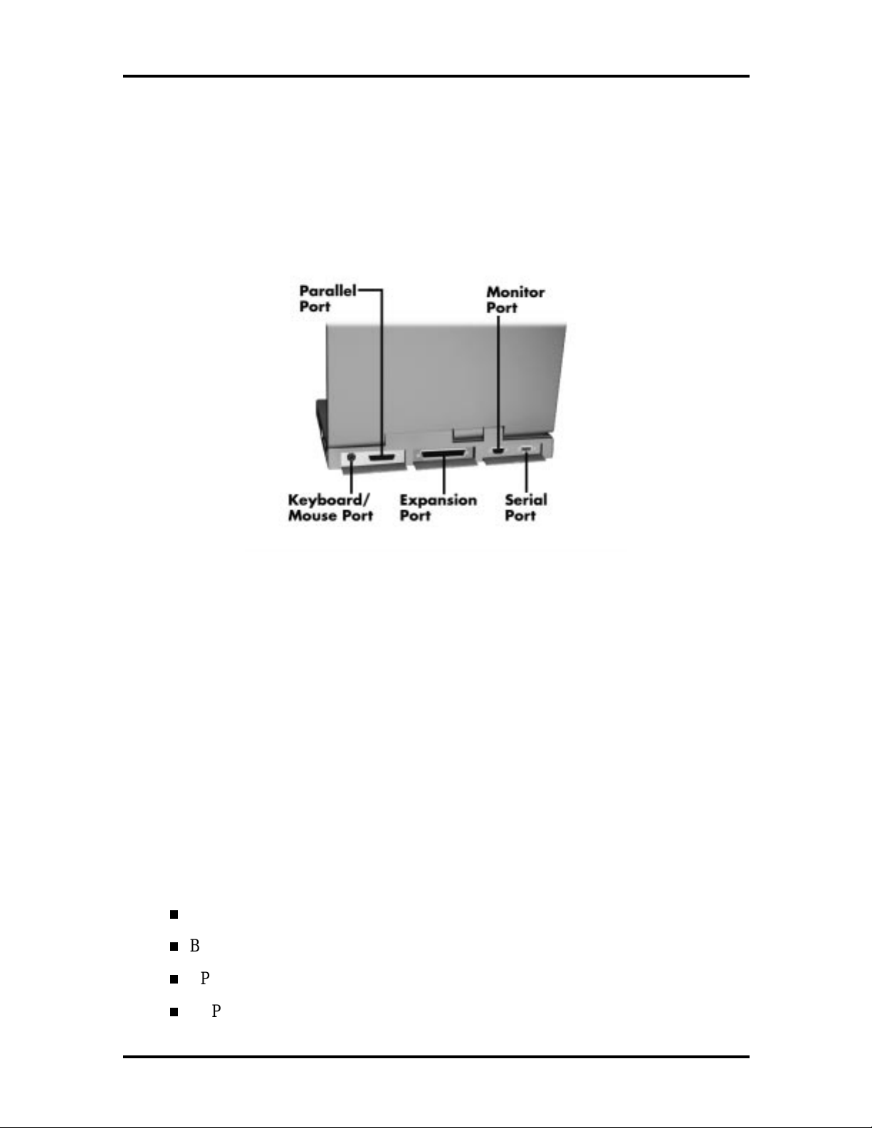
Figure 1-10 Rear Features
Keyboard/Mouse Port
Use the standard PS/ 2 port to connect an external PS/2-st yle mouse or a PS/2-st yle keyboard to the system. With an optional Y-cable adapter, you can connect both a mouse and a
keyboard at the same time. A serial mouse is not support ed.
Parallel Port (LPT1)
The 25-pin printer port provides a parallel interface to which you can connect a parallel
printer, pocket net work adapter or storage devices. Use this port to connect a parallel
printer or other parallel device. The port is IEEE 1284 compatible. It suppo rt s bi-directional
(A T) mode, Enhan ced Cap abilities Po rt (E CP) mode, E nha nced Parallel Port (EPP) mode,
(365SL-compatible), nibble mode, and byte mode (PS/2).
Th e p ar allel por t default is Extende d Capabilitie s P ort ( EC P) mo de . U se Se tup to change
the default to one of the following.
Uni-directional
Bi-directional
EPP
ECP
SOLD BY laptopia2005 DO NOT RESELL!!

SOLD BY laptopia2005 DO NOT RESELL!!
Expansion Port
This port provides a connection fo r NE C Versa options including the NEC PortBar 6000,
NEC Versa Docking Station 6000 Plus, NEC Versa MiniDock 6000 and the NEC Floppy
Disk Drive (FFD) Connector.
External Monitor (Video) Port
Use this 15-pin port t o att ach an external monit or to your NE C Ver sa. You can run the
LCD display and the external monitor simult aneously or run either alone.
Serial Port (COM1)
The 9-pin serial port pr ovides a serial interface to which you can connect an RS-232C
device such as an external serial printer or modem. A serial mouse is not supported.
Technical Information 1-11
HARDWARE OVERVIEW—INTERNAL COMPONENTS
Review the following sections for a description of the system’s internal hardware.
Battery Pack
The system uses a rechargeable lithium-ion (Li-Ion) battery as its transient power sour ce.
The battery pack installs in the compartment next to t he VersaBay II on t he bottom of the
NEC Versa. The battery stor es 14.4 vo lts with a 2600 mAh capacity.
The battery pack powers the NEC Versa for appro ximately 2 hours. In addition, the user
detects ho w much battery power is available via the percentage displayed on t he st atus bar.
When battery power is getting low, connect the AC adapter to a wall outlet and recharge
the battery. It takes approximately 2 hours to recharge the battery whether or not the syst em is in use.
When battery power is very low, the power LED flashes amber.
Hard Disk Drive
A standard 2.5-inch 2. 1- GB or 3.1-GB hard disk drive ships with the system. The 2.1-GB
hard disk drive specifications are listed next.
Track-t o-track seek r ate 4 ms
Average seek time 13 ms (read) 14 ms ( wr ite)
Revolutions per minute 4000
Data transfer rate 16.6 MB/sec
Internal data rates 39.1~61.6 Mbit/sec
SOLD BY laptopia2005 DO NOT RESELL!!
SOLD BY laptopia2005 DO NOT RESELL!!
1-12 Technical Information
Increase the system hard disk space by installing another hard disk driv e in the V er saBay II
slot in the fr ont of the computer using the optional hard disk drive adapter kit.
Diskette Drive
The interchangeable 3.5-inch 1.44 MB diskette drive inst alls in the front of the system in the
VersaBay II slot .
Versa Bay II SuperDisk LS-120 Drive
The interchangeable SuperDisk LS-120 drive is a do wnward co mpatible diskette drive that
can be used wit h either a 120 MB flo p tical disk or t he a standard 1. 44 MB 3.5-inch diskette.
20X CD-ROM Reader
A 20X CD-ROM reader ship s with the NEC Versa 6060. T he interchangeable twenty-speed
CD-ROM reader features t he latest in CD-ROM technology. It installs in the front of the
system in the VersaBay II slot. The CD-ROM reader is assigned to the next available drive
letter. T he CD-ROM reader operates at different speeds depending on whether the CD in
use contains data or music. T his improves video and sound quality.
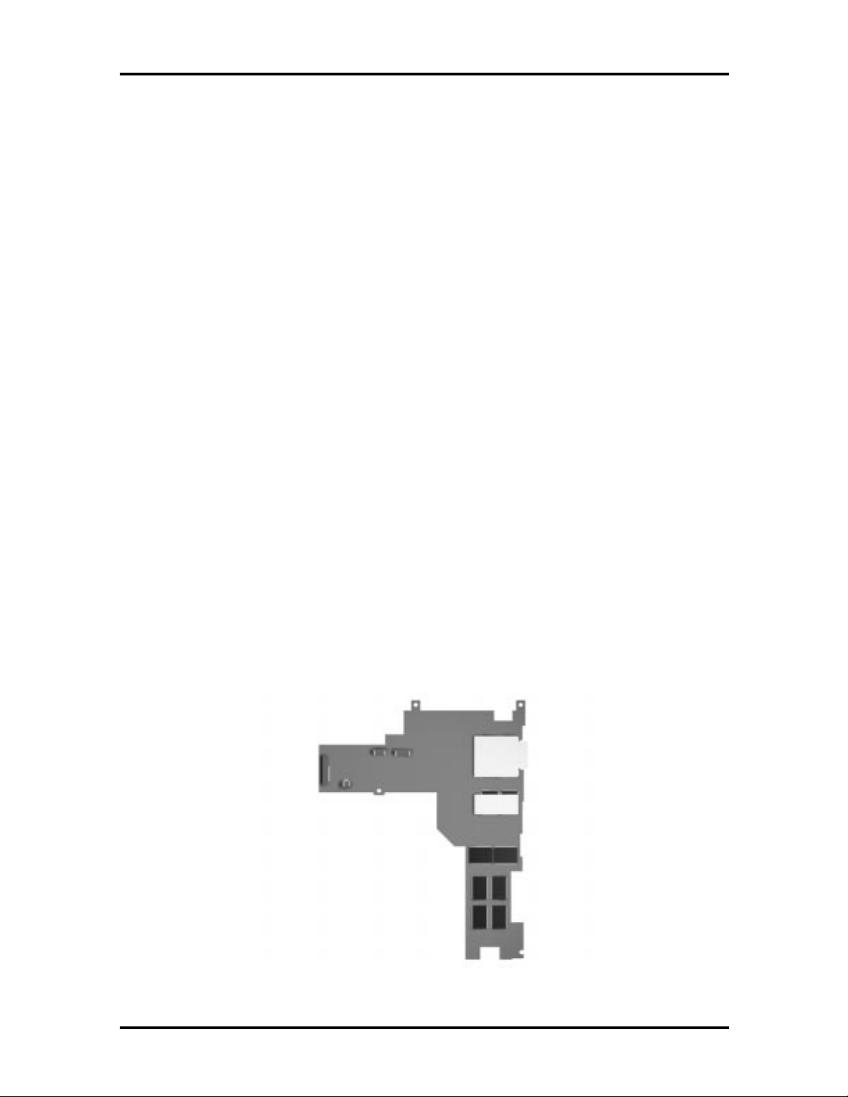
CPU Board
The CPU board (G8YJKB) is a L-shaped board located above the I/O board. The CPU
board also has a fan that exhausts on the right side of the notebook.
The NEC Versa 6060 models ship with Intel’s P55CLM/166 MMX installed on the CPU
board. The board uses the industry standard PCI interface, with a 66 MHz bus speed.
Figure 1-11 CPU Board Layout
SOLD BY laptopia2005 DO NOT RESELL!!
SOLD BY laptopia2005 DO NOT RESELL!!
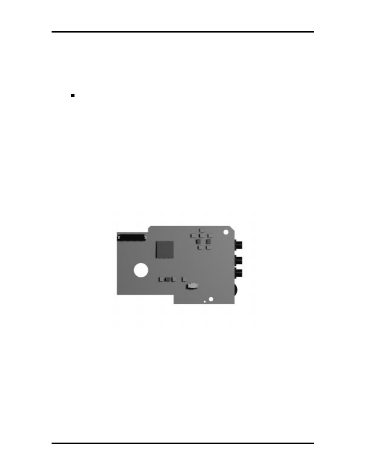
Audio Board
Th e a ud io b oar d ( G8 YZK) pro vides the N EC Vers a system with its au dio capabilities via
line-in jack, and headphone/microphone jacks. It is sit u ated on to p of the CPU board. The
audio board integrates the following features:
ESS Technology Plug and Play support
ES1869S
Integrat ed Music Synthesis, ESFM™ and Stereo Digital to Analog Converter
(DAC) FM Synthesizer
16 bit Stereo with ESFM
4.0KHz to 44.1KHz Sampling Rate
Sound Blaster Pro compatible
Technical Information 1-13
7 Channe l Mixer
Integrated S patializer® 3D ster eo sound.
Figure 1-12 Audi o Board Layout
SOLD BY laptopia2005 DO NOT RESELL!!

SOLD BY laptopia2005 DO NOT RESELL!!
1-14 Technical Information
AMP Board
The system Graph board (G8YAN) houses a variety of connectors and contr ols, including
the DIMM connecto r s. These are identified in the diagr am shown in Appendix A.
I/O Board
The system I/O board (G8YKA) contains peripheral subsystems including serial, parallel
and video port s, and charger. I t is located underneath the CPU board. Refer t o Appendix A
for a list of connectors.
CMOS Battery
The lit hium battery (3 Volts, 280 mAh capacit y) is attached to P8 on the I/O board. It provides battery backup and prevents data loss in the syst em’s complementary metal oxid e
semiconductor ( CMOS ) RAM. T his memory area contains infor mation on the system’s
configu ra tion like date, t ime, drives, and memory. The CM OS batter y lasts approximately
three years.
Bridge Battery
The bridge batter y saves the memory contents and system status for at least up to 5 minutes
while in Suspend mode. It is connected to the I/O board via connector P9. The AC adapter
maint ains voltage in the br idge batt er y when the system is power ed on or off. The bridge
battery stores 7.2 Vo lts, 70 mAH.
SYSTEM MEMORY
The Graph board provides 16 MB (5 V EDO) o f standard RAM.
Optional memory with a value o f 16-, 32-, or 64-MB can be added to increase system
memo r y up to a maximum of 80-MB (60 ns 3.3V EDO access). In addition, 256-KB of
read-only memory (ROM), 1 x 28F020, enables the system BIOS to be flashed.
The system provides 2 MB of video.
The follo wing Cache RAM is pr ovided:
L1: 16 KB (Internal Pentium)
L2: 256 KB write back (External).
Memory Map
The system supports system and video shadowing, both controlled through complementary
metal oxide semiconductor (CMOS). T he system supports BIOS as a cacheable area with
write pr otection. Table 1-2 lis ts t he syste m's memo ry ma p.
SOLD BY laptopia2005 DO NOT RESELL!!

SOLD BY laptopia2005 DO NOT RESELL!!
Table 1-2 Memory Map
MEMORY SPACE SIZE FUNCTION
000000-0003FFh 768 bytes BIOS Interrupt Vector Table
000400-0004FFh 256 bytes BIOS Data Area
000500-09FFFFh 640 KB Applic ations Memory ( used by t he OS, device
0A0000-0AFFFFh 64 KB Video Buffer (EGA and V GA)
0B0000-0B7FFFh 32 KB Video buff er ( monochrome, CGA color, VGA
0B8000-0BFFFFh 32 KB Video B uff er ( CGA, EGA color, and VGA c olor)
0C0000-0CBFFFh 48 KB Video ROM (EGA and VG A )
0CC000-0CFFFFh 16 KB Unused, ( Reserved f or adapter ROMs and other
Technical Information 1-15
drivers, TSRs, and al l DOS applications)
monochrome)
devices requiring ROMs)
0D0000-0DFFFFh 64 K B Used by Adapter ROMs (i.e., network controllers,
hard disk controllers, SCSI host adapters)
0E0000-0EFFFFh 64 KB Used by System ROM adapters (i. e., network
controllers with boot capability)
0F0000h-0FFFFFh 64 KB Sy stem AMIBI OS (includes Setup and hard disk
drive utilities)
100000h-1FFFFFF 32 MB Built-in Extended Memor y
2000000-5FFFFFF 64 MB Extended Memory
SYSTEM VIDEO
The system's LCD o per ates using the NeoMagic NMG4 Controller. Video signals travel
from the controller through the system's 15-pin D-S UB connector.
System video integrates a PCI-bus interface. The system ships with 2 MB Video RAM
(VRAM). It supports video modes up to 1024 x 768 with 64K colors in LCD mode.
See A pp endix B for a list of vid eo modes.
PARALLEL INTERFACE
The system' s parallel interface integrates National Semiconductor’s PC87338 chip with a
25-pin D-subconnector. T he por t is located o n the system's rear panel.
The modes of operation available fo r a PC87338 chip are:
comp atibility mod e
nibble mode
SOLD BY laptopia2005 DO NOT RESELL!!

SOLD BY laptopia2005 DO NOT RESELL!!
1-16 Technical Information
byte mo de
Ex tended Capabilities Port (ECP)
Enhanced Parallel Port (EPP).
The user selects between four parallel interface modes using Auto Setup. T hese include
un idir ec tional, bid ire ctiona l, extended or e nhanced. Unid ire ctiona l mode sends data out put
from the standard ISA port only. Bidirectional mode sends data using the standard ISA port
or PS/ 2 technology. Enhanced mode enables high speed data transmission to occur using
either th e u nidire ctional or bidir ec tional modes.
The default parallel port address is 378h and the interrupt level is IRQ07. Pin locations for
the parallel interface are listed in Appendix A.
SERIAL INTERFACE
The RS-232C serial port is a 9-pin D-sub connector on the system’s rear panel. The serial
port consists of a 16550A and 16450 compatible serial port co ntr oller with a progr ammable
baud rate up to 115,200 bps. The serial por t connects an RS-232C device or an external
modem. The default serial port address is 3F8h (COM1) and the interrupt level is IRQ04.
NEC VERSA CHIP SET
Refer to Table 1-3 for a quick summary of chip types used in the system. See the Abbr eviations section at the beginning of this manu al for a translation of chip technologies.
Table 1-3 NEC Versa Series Chip Ty pes and Technologies
CHIP MANUFACTURER DESCRIPTION TECHNOLOGY
Intel Pentium P55CLM Intel 166 MHz CPU 320-pin T CP
82439TX (MTXC) Intel M-Triton System Controller 324-pin BGA
82371AB (PIIX4) Intel M-PCI IDE ISA Xcelerator 324-pin TQFP
NM2160 NeoMagic VG A Controller 176-pin FQFP
PC87338 National
Semiconductor
Diskette Controller, IDE,
Parallel Interface
100-pin TQFP
M38813E Mitsubishi Keyboard Controller 64-pin TQFP
PC1131 Texas Instruments PC Car d Controller 208-pin Q FP
ES1869A ESS Technologies Sound Controller 100-pin PQF P
SOLD BY laptopia2005 DO NOT RESELL!!

SOLD BY laptopia2005 DO NOT RESELL!!
Intel Pentium P55CLM Microprocessor
The 166 MHz Intel Pentium micr oprocessor with MMX technology used in the NEC Versa
se ries c ompu ter is built on Intel’s adva nced 2.5V BiCMOS silicon technology. The CP U
has on-ch ip d ua l-p roc essing, a local mu ltipr ocessor inte rrupt con troller, and power management features. NE C adopted t he chip specifically for its pipelined Floating Point Unit
(FPU) , and local in ter rupt mana gement.
M-Triton System Controllers
NEC implements Intel’s Mobile Triton technology (MTDP 8249TX and MTSC 82371TX)
for s evera l of the not ebook’s s ubsyste ms including the DRAM cont roller , Se c ond L e vel
Cache Controller and PCI Bus interface. The Mobile Trito n PCI set features include:
direct mapped organization write-back policy
fully synchronous 33 MHz PCI bus interface.
Technical Information 1-17
256K X Flash ROM
The N28F020 flash ROM is a 32-pin, plastic lead chip carrier (PLCC). The chip allows easy
updates to the system's BIOS if needed. More specifically, t he ROM is flashed electronically, insta lling th e latest BIOS re visions to the syste m. It is po ssible to reprogram the BIO S
up to 100,000 times. See Section 2, Setup and Operation, for BIOS update procedures.
The N28F020 provides the system upgrade capability as well as t he follow ing:
256 KB memory
Quick- Pulse Progra mmin g Algorithm
150 nanoseconds (ns) maximum access time
ET OX Nonvolatile flash te chnolo gy
CMOS low power consumption
ROM BIOS
The system uses a Flash ROM known as the system's ROM BIOS to store machine language programs. The BIOS size is 256 KB, consisting of the system utility (f or the Au to
Setup), system BIOS, video BI OS, and Power Management.
The BIOS programs execute the power-on self-test (POS T), initialize CPU controllers, and
interact with the LCD indicator panel, diskette drive, hard drive, communication devices
and peripherals. T he system BIOS also contains Auto Setup and provides VGA contro ller
support. T he ROM BIOS is copied into RAM (shadowing) for optimum performance.
The ROM BIOS cont ains both the system and video BIOS. The system BIOS is located in
the upper portion of the device; video BIOS is located in the lo wer portion. System BIOS is
located between F0000h-FFFFFh.
SOLD BY laptopia2005 DO NOT RESELL!!

SOLD BY laptopia2005 DO NOT RESELL!!
1-18 Technical Information
The BIOS often changes after the product release to pro vide enhanced features or bug
fixes. T o acquire the latest BIOS release, the ROM is flashed electro nically allowing the
BIOS update to occur without removing the ROM. See Section 2, Setup and Operation, for
BIOS upgrade procedures.
VGA Controller
The NeoMagic NM2160 is a PCI 64-bit Graphics Accelerat or. The integrated prog r ammable linear address feature accelerates the graphics user interface (GUI) performance. The
contro ller also supports Hardware Multimedia and VESA interface standards. The controller provides advanc ed power management that helps to minimiz e p ower u sage in the follo wing modes:
normal operation
Standby (sleep) mode
panel off pow er sa ving modes.
Parallel Interface
The PC87338VJG chip is a 100-pin Thin Quad Flat Plastic (TQFP) chip. The cont roller
changes 8-bit parallel data into serial data and writes the data to the diskette. Conversely,
the serial data is transmitted from the diskette into parallel data, where it remains until the
read operation takes place.
Additional PC87338VJG chip operations include:
ISA co mpa tib ility
low-power CMOS with enhanced power-down mode
Keyboard Controller
The keyboard contro ller (M38813E) supports a PS/2-st yle keyboar d, mouse and password
security feature. Refer to Appendix A for keyboard interface connector pin assignments.
When data is written to the output buffer, the controller generates an interrupt, and requests
the CPU to receive the data. The contr oller automatically adds an even parity bit to t he dat a
sent and waits for a response. The device mu st acknowledge that the data was successfully
received by sending a response to the contr oller for each byte of data received.
SOLD BY laptopia2005 DO NOT RESELL!!
 Loading...