


PROPRIETARY NOTICE AND LIABILITY DISCLAIMER
The information disclosed in this document, including all designs and related materials, is
the valuable property of NEC Computer Systems Division, Packard Bell NEC, Inc.
(NECCSD, P BNEC) and/or its licenso rs. NECCSD and/o r its licensors, as appropriate, reserve all patent, copyright and other proprietary rights to this document, including all design, manufacturing, repro duction, use, and sales r ights thereto, except to the extent said
rights are expressly granted to others.
The NECCSD product(s) discussed in this document are warranted in accordance w ith the
terms of the Warranty Statement accompanying each product. However, actual
performance of each such product is dependent upon factors such as system configuration,
customer data, and oper ator control. Since implementation by customers o f each pro duct
may vary, the suitability of specific product configurations and applications must be
determined by the customer and is not warrant ed by NECCSD.
To allow for design and specification improve ments, the information in this document is
subject to change at any time, without notice. Reproduction of this document or portions
thereof without prior written approval of NECCSD is prohibited.
FaxFlash is a service mark of NEC Comput er Systems Divisi on (NECCSD), Packard Bell NEC, Inc.
NEC is a registered trademark, Versa is a U.S. registered trademark, MiniDock, VersaBay, VersaGlide, and
PortBar are trademarks, and UltraCare is a U.S. registered service mark of NEC Corporation, used under
license.
All oth er product, brand, or trade names used in this publication are the property of their respective owners
.
First Printing — September 1997
Copyright 1997
NEC Computer Syste ms D ivision, Packar d Bell NEC, Inc.
1414 Massachusetts Avenue
Boxborough, MA 01719
All Rights Reserved

vii
Preface
This service and reference manu al contains the technical information necessary t o set up and
maintain the NEC Versa® MiniDock 6000™. I t also provides hard ware and interface information for users who need an overview of the docking station’s design. The manual is
written for NEC-trained customer engineers, system analysts, ser vice center personnel, and
dealers.
The manual is organized as follows:
Section 1 Technical Information, pr ovides an overview of the hardware and int er face
components. System specifications are listed including dimensions, weight, environment,
safety compliance, and power consumption.
Section 2 Setup and Operation, takes the authorized service technician or dealer from
unpacking to setup and oper ation. The section includes a description of docking station
connectors, operat ing controls, and software.
Section 3 Troubleshooting and Repair, pro v ide s disasse mbly and assembly p roce-
dures, and an exploded-view diagram of the docking station with part numbers.
Appendix A Connector Locations and Pin Assignments, provides a list of the internal
connector pin assignments and a list of external pin assignments.
An Index is included fo r convenience.

Abbreviations
ix
Aampere
AC alternating current
AT advanced technology
(IBM PC)
BBS Bulle tin Board System
BCD binary-coded dec imal
BIOS basic input/out put system
bit binary digit
bp i bits per inch
bps bits per second
BUU BIOS Upg rade Utilit y
C centigrade
Cache high- speed buffer storage
CAM constant ly addressable memory
CAS column address stro be
CD-ROM compact disk-ROM
CGA Color Graphics Adapt er
CGB Color Gr aphics Board
CH channel
clk clock
cm cen timeter
CM OS comp lement ary metal oxide
semiconducto r
COM communication
CONT contrast
CPU central processing unit
CRT c athode-ray tube
DAC digital-to-analog converter
DC direct current
DIP dual in -line package
DLAB Divisor Latch Address bit
DMA direct memory access
DMAC DMA controller
DOS disk operating system
DRAM dynamic RAM
DTE data ter minal equipment
ECC error checking and correction
EDS error detecting system
EGA Enhanced Graphics Adapt er
EPP enhanced p arallel port
EPROM erasable and pr ogrammable
ROM
EVGA Enhanced Video Graphics
Array
F Fahrenheit
FAX facsimile tran smiss ion
FCC Federal Communicat ions
Commission
FG frame ground
FM frequency modulation
Fn Function
FRU field-replaceable unit
GB gigabyte
GND ground
HDD hard diskdr ive
HEX hexadecimal
HGA Hercules Graphics Adapter
Hz hertz
IC integrated circuit
ID identification
IDE inte lligent device electron ics
IDTR interrupt descriptor table
register
IMR Interrupt Mask register
in. inch
INTA interrupt acknowledge
IPB illustrated parts b re akdown
IRR Interrupt Request register
ISA Industry Standard Architecture
ISR In Service register
I/O input/output
IPC integrated peripheral contro ller

x Abbreviations
ips inches pe r second
IRQ interrupt request
K kilo (1024)
k kilo (1000)
KB kilobyte
kg kilogram
kHz kilohertz
kV kilovolt
lb pound
LED light-emitt ing diode
LSB least- significant bit
LSI large-scale integration
Mmega
mA milliamps
max maximum
MB megabyte
MFM modified frequency modulation
MHz megahertz
mm millimeter
ms millisecond\
MQFP metal quad flat package
MSB most-significant bit
NASC National Aut ho r ized Service
Center
NC not co nnected
NDP numeric dat a processor
NMI Non-maskable Interrupt
ns nanosecond
NSRC National Service Response
Center
PAL programmable array logic
PC per sonal computer
PCB pr inted circuit board
PCI pe rip herals comp on ent
interconnect
PFP plastic flat package
PIO parallel input/output
PJQFP plastic J-lead quad flat pack
PLCC plastic lead chip carrier
PLL ph ase lock lo op
p-p peak-to-peak
PPI programmable peripheral
interface
PQFP plastic quad flat package
PROM progra mmable ROM
QFP quad flat pack
RAM random-access memory
RAMDAC RAM digital-to-analog
RAS row ad d r ess strobe
RGB red green blue
RGBI red green blue intensity
ROM read -only memo ry
rpm revolutions per minute
R read
RTC real-time clo ck
R/W read/write
Sslave
SCSI Small Computer System
Interface
SDLC Synchrono us Data Link
Contr o l
SG signal ground
SIMM single inline me mory module
SQFP silver quad flat package
SVGA Super Video Graphics Array
SW switch
TQFP Thin-quad flat package
TSC Technical Support Center
TTL transistor/transisto r logic
tpi tracks per inch
UART univer sal asynchronous
receiver/transmitter
Vvolt
Vdc volts, direct current
pixel picture element

VESA video electronics standards
association
VFO variable fr equency oscillato r
VGA Video Graphics Array
VLSI ver y large-scale int egr ation
VRAM vir tual RAM
Wwatt
µf microfarad
µPD microprocessor
µs microsecond
Ω ohm
Abbreviations xi

iii
Contents
Preface.........................................................................................................................vii
Abbreviations............................................................................................................... ix
Section 1 Technical Information
Hardware Overview..................................................................................................... 1-2
Front and Top Features......................................................................................... 1-2
Left Features......................................................................................................... 1-4
Right Features....................................................................................................... 1-5
Rear Features........................................................................................................ 1-6
NEC Versa MiniDock 6000 Chipset............................................................................. 1-8
PCI Bus-t o CardBus Controller (PCI1131)........................................................... 1-8
PCI to ISA Controller (PCIset 82380AB) ............................................................. 1-8
PCI to PCI controller (PCIset 82380FB)............................................................... 1-9
IDE Controller (PCI0646U).................................................................................. 1-9
I/O Address Map......................................................................................................... 1-9
In terru pt Availab ility.................................................................................................... 1-10
Specifications............................................................................................................... 1-11
Section 2 Setup and Operation
Unpacking the Unit...................................................................................................... 2-1
Environment ......................................................................................................... 2-1
Hardware Setup........................................................................................................... 2-1
Preparing the NEC Versa for Docking .................................................................. 2-3
Docking the NEC Versa........................................................................................ 2-5
Undocking the NEC Versa.................................................................................... 2-9
Software Setup............................................................................................................ 2-10
Plug and Play Soft ware Setup ............................................................................... 2-10
Running the Se tup Utilit y............................................................................................. 2-10
Us ing the Setup Utility.......................................................................................... 2-11
Section 3 Troubleshooting and Repair
Preventive Maint enance............................................................................................... 3-1
Cleaning the Docking Statio n’s Exterior................................................................ 3-1
Cleaning the Docking Statio n’s Interior................................................................. 3-2

iv Contents
Protecting the Disk Drives .................................................................................... 3-2
Required Tools and Equipment .................................................................................... 3-2
Disassembly and Reassembly........................................................................................ 3-3
Top Cover............................................................................................................ 3-4
Internal Components ............................................................................................. 3-9
Illustrated Parts Breakdown......................................................................................... 3-16
Service Informatio n...................................................................................................... 3-18
Technical Support........................................................................................................ 3-19
Product Information ..................................................................................................... 3-19
Ordering Informatio n From FaxFlash........................................................................... 3-20
Appendix A Connector Locations and Pin Assignment
Figures
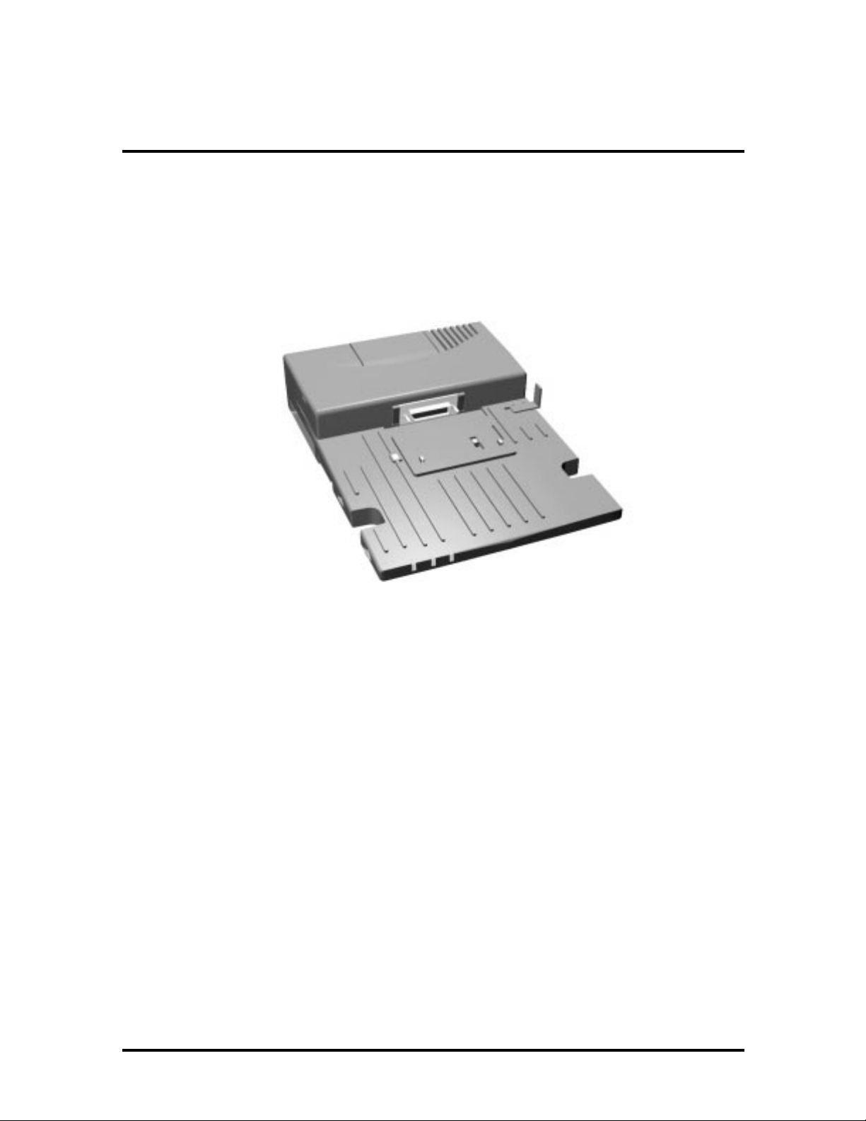
1-1 NEC Versa MiniDock 6000........................................................................... 1-1
1-2 NEC Versa MiniDock 6000 Front and Top Features...................................... 1-2
1-3 NEC Versa MiniDock 6000 LEDs................................................................. 1-3
1-4 NEC Versa MiniDock 6000 Left Features...................................................... 1-4
1-5 NEC Versa MiniDock 6000 Right Features.................................................... 1-5
1-6 NEC Versa MiniDock 6000 Rear Features..................................................... 1-6
2-1 AC Power Cable Connection.......................................................................... 2-2
2-2 Main Power Switch........................................................................................ 2-3
2-3 NEC Versa Expansion Port Cover.................................................................. 2-4
2-4 Stowing the Expansio n Port Cover................................................................. 2-4
2-5 Docking Status LEDs..................................................................................... 2-5
2-6 Adjusting the AC Port Guard......................................................................... 2-6
2-7 Lowering the NEC Versa ont o the MiniDock................................................. 2-6
2-8 Docking the NEC Versa................................................................................. 2-7
2-9 Opening the LCD Panal.................................................................................. 2-7
2-10 Power Button................................................................................................. 2-8
2-11 Undocking and Suspend/Resume Buttons....................................................... 2-9
2-12 Removing the NEC Versa .............................................................................. 2-10
2-13 Main Setup Screen......................................................................................... 2-12
3-1 Upper Shelter Co ver ...................................................................................... 3-4
3-2 Undock Lever Screw Lo cation....................................................................... 3-5

Contents v
3-3 Undock Shelter Screws.................................................................................. 3-6
3-4 Bottom of the MiniDock 6000 ....................................................................... 3-7
3-5 Interior of the MiniDock 6000........................................................................ 3-8
3-6 Fan Assembly Screws..................................................................................... 3-9
3-7 PCB Sub Screws............................................................................................ 3-10
3-8 Frame PCB Main........................................................................................... 3-11
3-9 Undock Unit Screw Lo cation......................................................................... 3-12
3-10 VersaBay Panel.............................................................................................. 3-13
3-11 Power Supply Unit......................................................................................... 3-14
3-12 PCB Sub........................................................................................................ 3-15
3-13 NEC Versa MiniDock 6000 IPB .................................................................... 3-16
A-1 Keyboard and Mouse Ports............................................................................ A-1
A-2 COM Port...................................................................................................... A-2
A-3 Printer Port.................................................................................................... A-3
A-4 Monitor Port.................................................................................................. A-4
List of Tables
1-1 NEC Versa MiniDock 6000 Chip Types and Technologies............................. 1-8
1-2 I/O Address Map ........................................................................................... 1-9
1-3 NEC Versa MiniDock 6000 Specifications..................................................... 1-11
3-1 NEC Versa Series MiniDo ck 6000 Disassembly Sequence.............................. 3-3
3-2 NEC Versa Series MiniDock 6000 Field-Replaceable Parts............................ 3-17
3-3 Packaging and Documentation Part Numbers................................................. 3-18
3-4 NEC Service and Information Telephone Numbers......................................... 3-18
A-1 Keyboard/Mouse Pin Assignments ................................................................. A-1
A-2 COM Port Pin Assignment s............................................................................ A-2
A-3 Printer Port Assignments................................................................................ A-3
A-4 Monitor Port Pin Assignments........................................................................ A-4
A-5 Docking Expansio n Port Assignments............................................................ A-5
Section 1
Technical Information
The NEC Versa
Versa 6000 Series notebook computer into a desktop system.
MiniDock 6000™ provides the user with a way to tr ansform his/her NEC
Figure 1-1 NEC Versa MiniDock 6000
1-2 Technical Information
HARDWARE OVERVIEW
MiniDock features ar e found on every surface of the unit . T o become familiar with these
features, read each of the following sect ions.
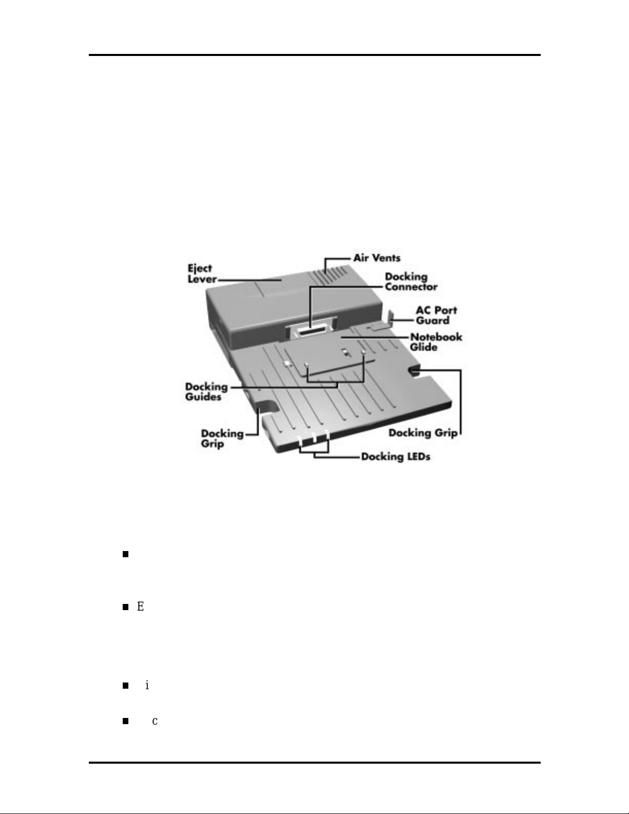
Front and Top Features
Features on the front and to p of the NEC Versa MiniDock 6000 are shown in the fo llowing
figure. Descriptions follow the figur e.
Figure 1-2 NEC Versa MiniDock 6000 Front and Top Features
Front and Top Feature Descripti ons
Docking Guides — ensure t hat your NE C Ver sa is aligned proper ly for docking.
These guides fit into specially placed notches on the bottom of the noteboo k
computer.
Eject Lever — disconnects the NEC Versa from the MiniDock do cking connector . Befor e pr essing the Eject lever, you must prepare your system fo r undo cking
by pressing the Undocking button or the Power button on the side of the MiniDock. (See Chapter 2, “Docking and Undocking, ” in the MiniDock 6000 User’s
Guide for details about undocking procedures.)
Air Vents — allow the MiniDock to cool properly. Keep the vents free of paper
and debris to allow for proper air circulation.
Docking Connector — fits the expansion por t on your NEC Versa to allo w for
docking.
Technical Information 1-3
AC Port Guard — keeps you from accidentally do cking the NEC Versa while it is
still p lugged into t he AC adapter. When the notebook is docked, the MiniDock
supplies power to r un t he system and charges the battery installed in the NEC
Versa notebook , but not the battery installed in the MiniDock 6000 VersaBay II.
Notebook Glide — allows you r notebo ok compute r to glide easily t owards the
docking connector during docking and away from the connector while undocking.
Docking Grips — give you the leverage you need to connect the expansion po r t
on the notebook computer to the docking connector o n the MiniDock.
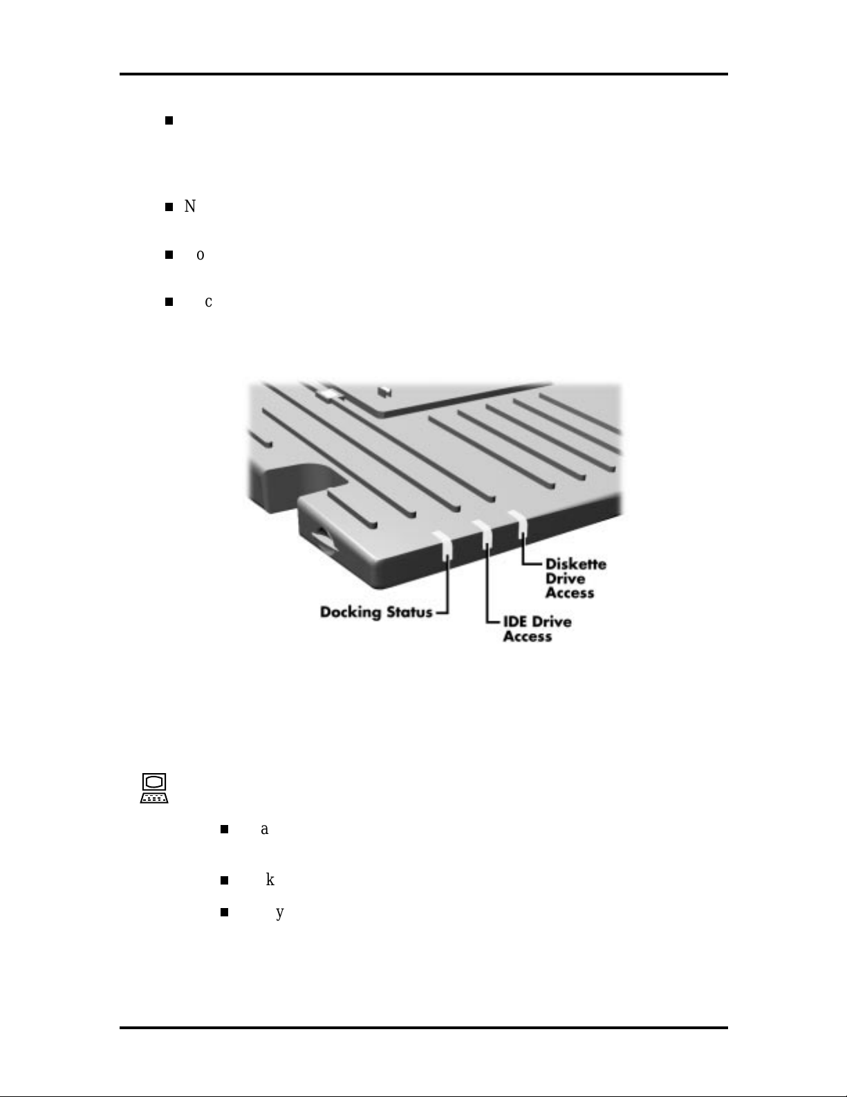
Docking LEDs — inform you of the current docking status, I DE dr ive access, and
diskette drive access. LEDs are shown in the following figure and LED states are
described after the figur e.
Figure 1-3 NEC Versa MiniDock 6000 LEDs
Status LEDs Descriptions
Docking Status – When power is on to the MiniDock, this LED lights as fol-
lows:
Steady green when the NEC Versa is properly docked, powered up, and
locked onto the MiniDock.
Blinks green while processing an undocking request.
Steady amber when power to t he MiniDock is on but no notebook computer is docked; when the computer is docked but not po wer ed on; or an
eject request was accepted and t he computer is ready for undocking.
1-4 Technical Information
IDE Drive Access – lights green when a CD-ROM, hard disk, or SuperDisk™
LS-120 drive installed in the MiniDo ck or NEC Versa is accessed.
Diskette Drive Access – lights green when a standard diskette drive installed
in the NEC Versa or MiniDock VersaBay II is accessed. Also lights green
when a diskette drive connected via an external FDD connector cable is accessed.
Left Features
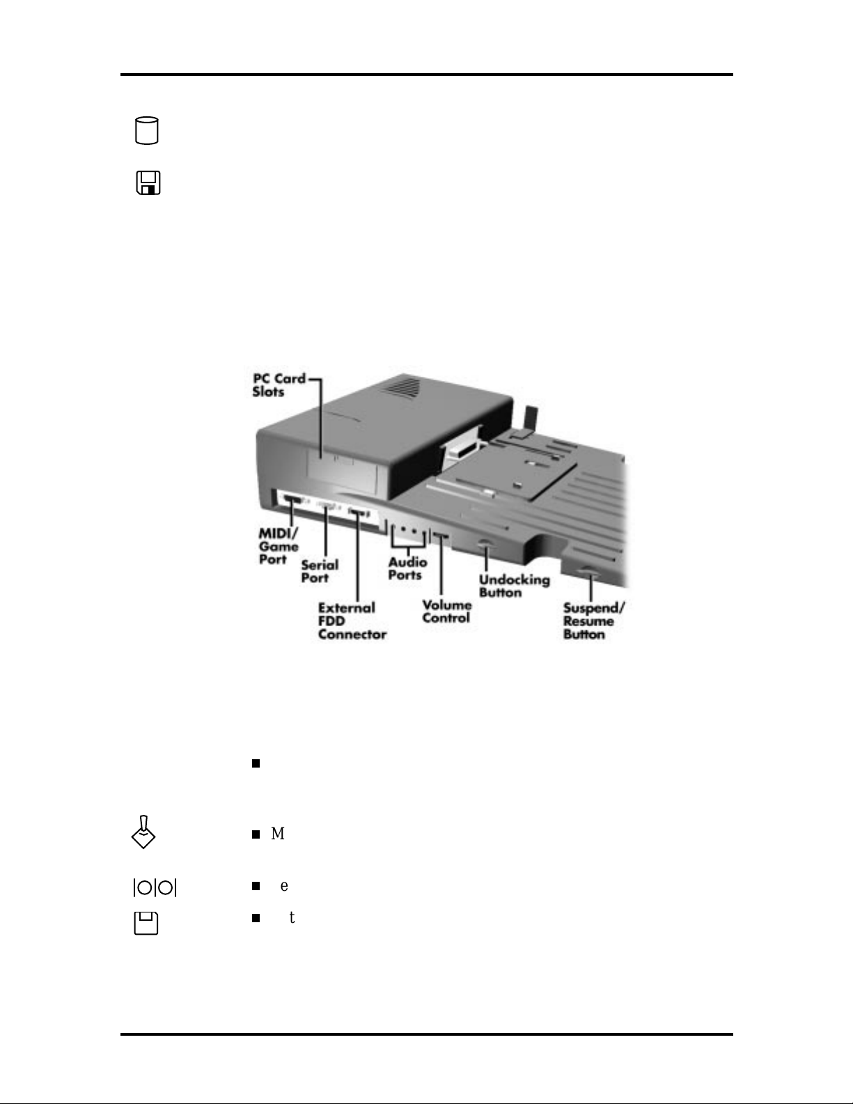
Features on t he left hand side of the MiniDock are shown in the follo wing figur e. Descriptions follow the figure.
Figure 1-4 NEC Versa MiniDock 6000 Left Features
Left Feature Descriptions
PC Card Slots — lets you install two Type II PC cards, one Type III
PC card, or one Type III card in the top slot and one Type II card in
the bott om slot for use while docked.
MIDI/Game Port — supports MIDI/game devices, such as a joystick
or MIDI keyboard.
Serial Port — lets you connect serial devices to the MiniDo ck.
External FDD Connector — lets you connect an optional External
FDD cable directly to the MiniDock.
Technical Information 1-5
Audio Port s — gives you the option of connecting ext er nal audio
devices including: a microphone, headphones, or speakers. You can
also connect other audio devices to use as an out put device or input
source.
Volu me Control —give s you co nt rol over the volume o f exte rnal
speakers or headphones attached to t he MiniDock.
Undocking Button —releases the locking mechanism and prepares
the NEC Versa for undocking. For warm undocking, you must press
the Undocking button before pressing the Eject lever to successfully
undock. (See Chapter 2, “Docking and Undocking,” for details about
undocking the system.)
If an eject request is rejected, the Docking LED retur ns t o solid
green.
Suspend/Resume Button — puts your NEC Versa into Standby
mode to co nserve energy. To ret ur n t o Operating mode, press the
but to n a second time.
Right Features
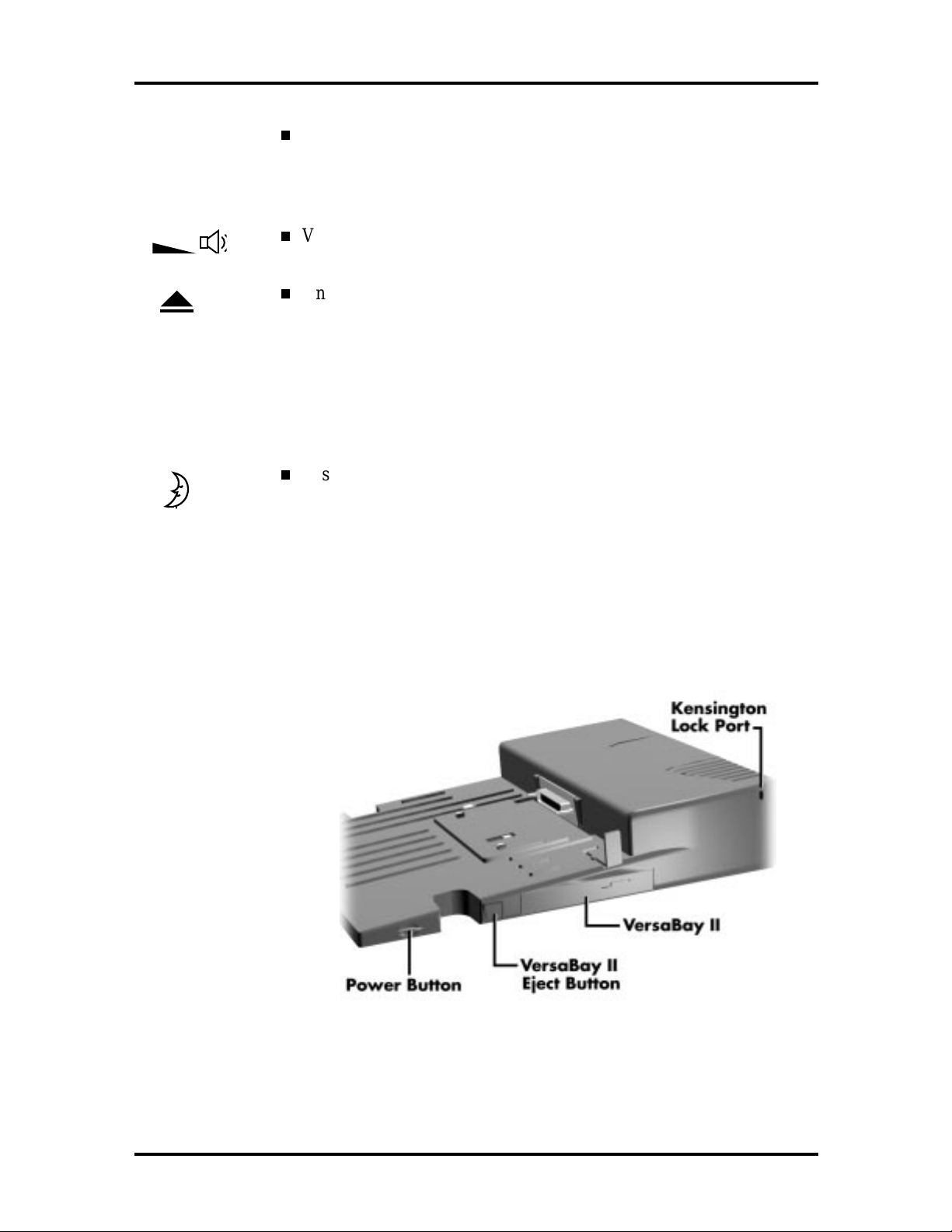
Features on t he right-hand side of the MiniDock are shown in the following figure. Desc rip tions follow the figur e.
Figure 1-5 NEC Versa MiniDock 6000 Right Side Features
1-6 Technical Information
Right Feature Descri ptions
Kensington Lock Po r t — lets you secure your MiniDock using an optional Kensington Lock.
VersaBay II — lets you install yo ur diskette or SuperDisk drive, CD-
ROM reader, seco nd hard disk drive, or ot her Ver saBay opt ion into the
MiniDock.
VersaBay II Eject Button — ejects a device installed in the MiniDock
6000 VersaBay II.
Power Button — lets you power on and off the NEC Versa notebook
computer docked on the MiniDock.
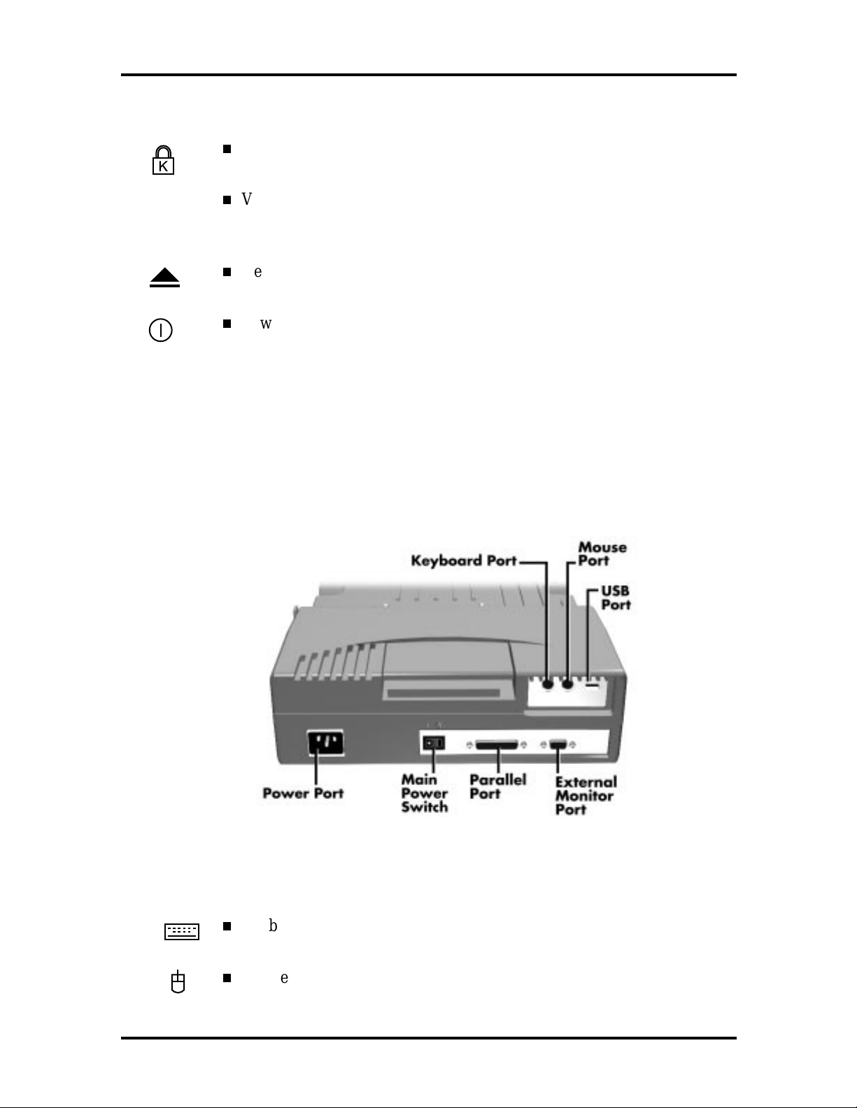
Rear Features
Features on the rear o f the MiniDo ck 6000 ar e shown in the following figure. Descriptions
fo llow the figure.
Figure 1-6 NEC Versa MiniDock 6000 Rear Features
Rear Feature Descriptions
Keybo ar d P ort — lets you connect a PS/2-style exter nal keyboard to your
MiniDock.
Mouse Po r t — lets you connect a PS/2-style external mo use to your
MiniDock.
Technical Information 1-7
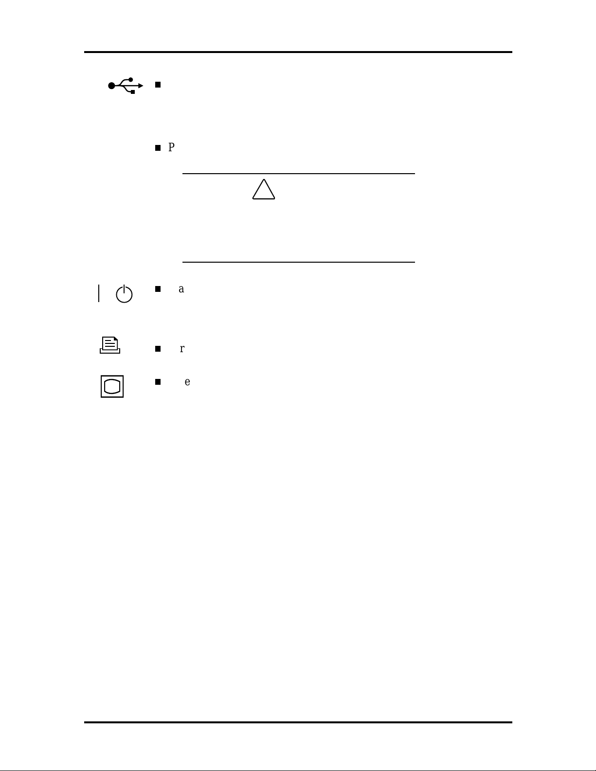
USB Port — lets you connect one or more USB devices to the Mini-
Dock. If your NEC Versa support s USB device connection, this port o n
the MiniDock wo r k s. I f your NEC Versa does not support USB device
connection, this port does not work.
Power Port — allows you to connect t he MiniDock to AC power.
!
Always use the power cable that ships with the
CA UT ION
MiniDock or one that is appropriate for your
country. See the cable listed in the MiniDock
6000 User’s Guide. Appendix A, Specificat ions
Main Power Switch —turns power on to the MiniDock. Pressing this
button t o remove power while the not ebook is docked and powered on
shuts down everything and can cause a system crash.
Parallel Port — lets you connect a parallel device to the MiniDock.
External Monitor Por t — allows you to connect an external monitor .
(You may need to press
Fn-F3
to get an image on the external monitor.
See your NEC Versa user’s guide for function key combinations.)
1-8 Technical Information
NEC VERSA MINIDOCK 6000 CHIPSET
Refer to Table 1-1 for a quick summary of the chip types used in t he system. See the
Abbreviations section at the beginning of this manual for a t r anslation of chip technologies.
Table 1-1 NEC Versa MiniDock 6000 Chip Types and Technologies
Chip Manufacturer Description Technology
PCI1131 Texas Instrum ents CardB us Contr oller 208- pin (TQFP)
PCIset 82380AB
(Moon PCI)
PCIset 82380AF
(Moon ISA)
PCI0646U CMD Tec hnology,
Intel PCI to ISA Support 160-pin MQF P
Intel PCI to P CI Support 208-pin SQFP
IDE Cont r oller 100-pin SQFP
Inc.
PCI Bus-to-CardBus Controller (PCI1131)
The PCI1131 supports two 32-bit CardBus credit-card-size add-in modules that give the
PC access to peripheral devices, such as modems, video pro gr a mming, printers, external
video monitors, and local area networks.
bandwidth significantly gr eater than that of other CardBus co nt r oller s
supports t wo 32-bit CardBus credit-card-size and also suppo r ts 16-bit PCMCIA
(Personal Computer Memory Card Industry Association) or PC Card add-in
modules.
PCI to ISA Controller (PCIset 82380AB)
This chip provides the docking station with docking control and hot insertion as applicable
to the PCI/ISA bus. The PCIset 82380AB integrates t he following in PCI/ISA technology:
supports full IS A including ISA masters
supports PCI at 25 Mhz to 33 Mhz
supports ISA at 7. 5 Mhz to 8.33 Mhz
provides byte swap logic, I/O recovery support, wait-st ate generation, refresh and
SYSCLK generation.
Technical Information 1-9
PCI to PCI Controller (PCIset 82380FB)
This chip provides the MiniDo ck with docking control and hot insertion. The PCIset
82380FB int egrates the following in PCI/ PCI technology:
efficient repeater architecture
supports full po wer management
high performance bridge supports back-to-back data transfer.
IDE Controller (PCI0646U)
NEC uses C MD Technolog y’s PCI t o IDE con troller, pr ov iding t h e follo wing:
standard PCI to Universal Serial Bus (USB) technology
complete driver suppo r t for all major operat ing systems including MS-DOS, Windows 3.1, Windows NT, Windows 95, and Novell NetWare
supports isochronous and asynchronous transfer types
supports dynamic “hot” insertion and removal of devices.
I/O ADDRESS MAP
Refer to Table 1-2 for the MiniDock address map.
Table 1-2 I/O Address Map
Address Function
0170 - 0177H IDE Contr oller (Secondar y )
01F0 - 01F 7H IDE Controller (Primary)
0376H Al ternate HDD, Control and Status
(Secondary)
0377H Al ternate HDD, Digital Input Register
(Secondary)
03F6H Alternate HDD, Control and Stat us
(Primary)
03F7H Alternate HDD, Digital Input Register
(Primary)
0C28H Docking Station Control Register
0C20H NVRAM P age S election Cont r ol Register
1D00 - 1DFF H 16 Pages of 128 byte/page NVRAM
1-10 Technical Information
INTERRUPT AVAILABILITY
The assignments associated with the MiniDock 6000 are as follows:
IRQ 0 — Timer
IRQ 1 — Keyboard cont ro ller
IRQ 2 — Cascade
IRQ 3 — * Modem
IRQ 4 — * Serial Po r t
IRQ 5 — * Audio
IRQ 6 — * Diskette drive
IRQ 7 — * Parallel Port
IRQ 8 — Real Time Clock
IRQ 9 — * IR Port
IRQ10 — IntA (Assigned by Windows 95 Cardbus driver)
IRQ11 — IntB (Assigned by Windows 95 Cardbus driver)
IRQ12 — * VersaGlide/Mouse
IRQ13 — Math Coprocessor
IRQ14 — Primary Hard Drive
IRQ15 — * Secondary Hard Drive (MD6000 Drive).
* These IRQ’s are available for reassignment (I RQ12 is available only with the NEC Versa
6020/6030).

Technical Information 1-11
SPECIFICAT IONS
Table 1-3 provides a complet e list of the NEC Versa Series MiniDock 6000 specifications.
Table 1-3 NEC Versa Series MiniDock 6000 Specifications
Item Specification
Chassis Conf iguration (Size)
Width:11.58 in. (297 mm)
Power
Connector Support
Depth:16.25 in. (416.6 mm)
Height (Back): 3.66 in. (94 mm)
Weight: 7.05 lb. (3.2 kg)
120 Volts, 1.5A, 60 Hz (North Ameri c a)
220-240 Vol ts, .9A, 50Hz (Eur ope)
Docki ng Connec tor
VersaBay II
Seri al RS-232C
Parallel EPP
MIDI Game port
VGA CRT
PS/2- sty le mouse port
PS/2- sty le keyboard port
Mic r ophone- in Port
micr ophone jack
connects to Versa expansi on c onnec tor
20-pin connector
9-pin connector
25-pin connector
15-pin connector
15-pin port
accepts a standard monophonic
Headphone
speaker
Line I n
Line O ut
USB 4 pin connector
Ex ternal FDD Connect or 26-pin connector
Indi c ator LEDs Docking status
IDE Drive Access
Diskette Driv e Access status
external audio source, stereo i nput to MiniDoc k .
connects to another audio system
accepts standard stereo headphone or ex ternal

1-12 Technical Information
Table 1-3 NEC Versa Series MiniDock 6000 Specifications (cont’d)
Item Specification
Standard Software
NEC MiniDoc k 6000 S etup utility
BIO S Update Diskette
Recommended Enviro nment
Temperat ur e: 41° to 95°F (5° to 35°C)
Storage Requirement s
Administrative Compliance
UL 1950 CSA C22.2 No. 950 (D3) CE E N60950; 1992 + A1+
Relat ive Humidity: 8% to 80% (noncondensing)
Temperature: –4° to 140°F (–20° to 60° C)
Relat ive Humidity: 5 to 95% (non-condensing)
A2; 1993 + A3: 1995 + A-4

Section 2
Setup and Operation
This section provides setup and operation info r mation for the NEC Versa MiniDo ck 6000.
This includes cabling, power-on verification and using the NEC Versa MiniDock 6000
comp uter’s Setup u tility.
UNPACKING THE UNIT
Find an area away from devices that generate st r ong magnetic fields (electric motor s,
transformers, etc.) P lace the shipping carton o n a st ur dy surface and carefully unpack the
unit. The carton contents include the NEC MiniDock 6000, AC power cord, software CDROM, and user documentation.
Environment
Use the NEC Versa MiniDo ck 6000 in a location that meets the follo wing environmental
conditions:
Temper ature: 41° to 95°F (5° to 35°C)
Humidity: 20% to 80% ( no ncondensing)
Stor e the NEC Versa MiniDock 6000 in a location that meets the following conditions:
Temper ature: –4° to 140°F (–20° to 60°C)
Humidity: 5% to 95% (noncondensing)
HARDWARE SETUP
The power cable that comes with the unit pro vides power to the NEC Versa MiniDock
6000 and the NEC Versa. Connect the MiniDo ck power cable as follows:
NOTE: Make sure to plug the power cable into
the MiniDock 6000 before docking the NEC
Versa.
Connect the power cable as follows.
Position the MiniDo ck on a flat sur face close to an AC outlet.
1.

2-2 Setup and Operation
Attach one end of the cable to the AC power port on the MiniDock.
2.
Attach the other end to a pro per ly grounded wall o u tlet.
3.
Figure 2-1 AC Power Cable Connection
Locate the main Power switch on t he back of the MiniDock. Press the
4.
white dot on the switch to turn on the MiniDo ck’s po wer . A vertical line
icon above the Power switch indicates that power is on.
!
Make sure the main P ower switch on the back of
the MiniDock is powered on before docking the
NEC Versa. Docking the NEC Versa while the
MiniDock is powered off can result in a system
crash. This caution applies to the Windo ws 95
operating system only.
CA UT ION

Setup and Operation 2-3
Figure 2-2 Main Power Switch
!
Disconnecting the power cable, turning off
CA UT ION
pow er by pressing the main Po wer s witch, or exper iencing a power ou tage while running the
MiniDock and NEC Ver sa can result in a system
crash.
Preparing the NEC Versa for Docking
Follow the procedure given next to prepar e the NEC Versa for docking.
1.
Set NEC Versa power for your system as follo ws.
If you have a Plug and Play NEC Versa, you can either put your syst em into Suspen d mode o r le ave it in full O peration mode for docking .
For example, an NEC Versa with Windows 95 running is a Plug and
Play system.
If you have a no n-Plug and Play system, tur n o ff system power before
docking. Syst ems running Windows for Workgroups or Windows NT
do not suppor t Plug and Play.
NOTE: Make sure your system is in t he
appropriate mode for docking.

2-4 Setup and Operation
If you are running the NEC Versa on AC power, disconnect the AC
2.
adapter cable from the NEC Versa.
On the back of the NEC Versa, open the expansion port cover and slide it
3.
underneath the expansion port.
Check that all other NEC Versa port covers are closed.
NOTE: Before disconnecting power,
save any open files or close open applications to avoid data loss.
Figure 2-3 NEC Versa Expansion Port Cover
Figure 2-4 Stowing the Expansion Port Cover
Verify that the power cord is plugged into the MiniDock and that
4.
MiniDock power is turned on. (See “Connecting the Power Cable” fo r
details.)
When the Docking Status LED lights steady amber, power to the MiniDock is turned on and it is ready for docking.

Figure 2-5 Docking Status LEDs
Docking the NEC Versa
Setup and Operation 2-5
Dock the NEC Ver sa in one of the following modes:
Cold Docking — wit h NEC Ver sa system power off. This method works
for all NEC Versa models that support docking.
Warm Docking — with NEC Versa power on, the system in Suspend
mode, and MiniDock power on. This procedure can be used with NEC
Versa systems that run the Windows 95 operating system.
Hot Docking — with NEC Ver sa po wer on and the system in full operation mode. This procedure can be used with NEC Versa systems with the
Wind ows 95 op er ating system.
Use the following steps to do ck the NEC Versa.
1.
Locate t he AC Port Guard on the MiniDock. You may need to adjust the
guard position to suit the size of your system. For wider systems that
need more room, slide the guard away from the MiniDock.
2.
Locate t he do cking connector and the do cking guides on the MiniDock.

2-6 Setup and Operation
Figure 2-6 Adjusting the AC Port Guard
For easier docking, close the LCD panel o n t he NEC Ver sa. ( T his is not
3.
required, but is recommended.)
Align the docking guides on the MiniDock with the docking grooves on
4.
the bottom of the NEC Versa. Lower the NEC Versa onto the MiniDock.
Once the notebook is proper ly seated on the docking guides, the docking
connector and the expansion port are properly aligned.
Figure 2-7 Lowering the NEC Versa onto the MiniDock
Verify that the Docking LED is a st eady amber color. This indicates that
5.
the MiniDo ck is ready for docking.

Setup and Operation 2-7
Place your fingers in the docking grips and your thumbs o n t he front of
6.
the NEC Versa. Firmly push against the computer with equal pressure
against the left front and right front of the NEC Versa. Continue to press
until the connection between the computer and the MiniDock is secure.
Figure 2-8 Docking the NEC Versa
NOTE: Keep the NEC Versa straight. If the computer is pushed at an angle, it does not dock properly.
If using the NEC Versa without an external monitor, open the LCD
7.
panel.
Figure 2-9 Opening the LCD Panel

2-8 Setup and Operation
Press the Power button on the front right side of the MiniDock to power
8.
on the NEC Versa. When the Docking Status LED lights a steady green,
the docking process has successfully completed and the NEC Versa is
powered on.
If no LEDs are lit, press t he main Power switch on the back of the
MiniDock t o power o n the MiniDock. Next, press the Po wer but ton
on the right side of the MiniDock to power on the NEC Versa.
If the Docking Status LED blinks green, push a little harder on the
NEC Versa to reseat it for do cking. This usually corrects the problem
and the LE D will light a stea dy g re en.
The LED continues to blink green when something has go ne wro ng
with the docking sequence due to an error or hardware failure. Proceed as follows:
Press the Eject lever to eject the NEC Versa from the MiniDock.
Check that the Docking Status LE D is amber.
Starting at step 2 in this pro cedur e, try redocking the system.
Figure 2-10 Power Button
Once docked, the NEC Versa is locked onto the MiniDock and cannot be
removed without following t he appro pr iate undocking procedure.

Undocking the NEC Versa
Undock your NEC Versa as follows.
1.
Check the status of your NEC Versa power:
If you are running Windows 95, you leave the system in Operation
mode to undock.
If you are running Windows fo r Workgroups or Windows NT, s a ve
your files, close any open applications, exit Windows and press the
Power button on the side of the MiniDock to power off the system.
2.
For easier undocking, close t he LCD panel. (This is not required, but is
recommended.)
Setup and Operation 2-9
Figure 2-11 Undocking and S uspend/Resume Buttons
3.
Press the Undocking button o n t he side of the MiniDo ck. T he Do cking
Stat us LE D blinks green. When the LED turns a steady amber, you are
ready to undock.
NOTE: Wait until the LED turns amber befo re
disconnecting the NEC Versa. You cannot undock the computer while the LED is green.

2-10 Setup and Operation
To use Windows 95 software to undock the NEC Versa, locate and select
the “Eject PC” icon in t he Windows 95 Start menu. When you select this
icon, a “Dock Change” window appears. T he Do cking Status LE D blinks
green and then changes to so lid amber .
Once the LED light s amber, press t he Eject lever on the back of the
4.
MiniDock and pull the NEC Versa forward to r emove it.
Figure 2-12 Removing the NEC Versa
SOFTWARE SETUP
Procedures for setting up the MiniDock so ftwar e depend o n whether the co mputer is a Plug
and Play system or a Non-Plug and Play system.
Plug and Play Software Setup
Plug and Play systems (for example the NEC Versa 6060 with Windows 95 installed) operate with a Plug and Play BIOS and require no special softwar e installation. Simply dock the
NEC Versa, and reboo t the system. The MiniDock is automatically configured for use with
the NEC Versa system.
RUNNING THE SETUP UTILITY
Setting up the software to use the MiniDock is easy to do. T he NEC MiniDock 6000 ships
with a CD-ROM containing an online user’s guide and CardWizar d® PC card drivers. Follo w the in structions in this section t o in stall the o nline user ’s guide on your NE C Ver sa and
load the appropriate drivers.

NOTE: If your system requires the CardWizard
drivers, yo u must in st all the m b efore docking
fo r the first time . Failure to inst all the dr ivers
first can re sult in a syst em malfunc tion.
Using the Setup Utility
Th e setup utility inst alls the online MiniDock user’s guide an d the appr opriate PC card dr ivers for the o per ating system. Do so as follows:
1.
Make sure the CD-ROM reader is installed in the NEC Versa and that t he
NEC Versa is not docked.
2.
Power up t he NEC Ver sa.
3.
In sert the NEC M iniDoc k S etup Utility CD into the reade r a nd clo se th e
tray.
Setup and Operation 2-11
4.
Proceed as follows:
If your system is set t o AutoPlay, the setup interface screen appears.
Go to the next step.
If your system is not set to AutoPlay or does not have AutoPlay
in Windows for Wor kgroups, select Ru n from the File menu in
Program Manager.
in Windows 95 or Windows NT, select Run from the Start menu.
In the Run field, type
designation) and press
5.
Whe n a M iniDock softw are setup sc re en (simila r to t he one shown ne xt )
d:\install.exe
Enter
or select OK.
(where d is yo ur CD- ROM reader
appears, pro ceed as follows.

2-12 Setup and Operation
Figure 2-13 Main Setup screen
In Installation Type, select your operat ing system. Choose Wind ows
3.11 (for Windo ws for Workgro ups), Windows 95, or Windo ws NT
4.0.
In the Applicat ions and Drivers Selection box, highlight a selection and
press Setup.
Windows 95 offers only one setup option — to install the online
user’s guide. This is optional. (Windows 95 comes with its own
utility for PC cards. )
Windows 3.11 and Windows NT offer two setup options, one to
install the CardWizard drivers and one to install t he user’s guide.
Loading the user’s guide is optional. However, you must load the
PC Card slot drivers in o rder to use the slots.
After you press t he Setup button, t he system displays a Windows setup
screen.
Follow the o n-screen instructions t o in st all your selectio n.
6.
If you have another selection to load, repeat st eps 4 and 5.
From the Main Setup screen, press Exit.
7.
The NEC Versa on the MiniDock is now fully functional!

Section 3
Troubleshooting and Repairs
This section conta ins preventive and corr ective maintenance pr ocedures for the NEC Versa
MiniDock 6000. The first part of the section describes cleaning procedures and preferred
handling procedures for sensitive components.
The second part of the section contains removal and replacement procedures for all field
replaceable parts. The remainder of the section includ es an Illustrat ed Parts Breakdown
(IPB), that identifies parts and corresponding part numbers for ordering purposes.
PREVENTIVE MAINTENANCE
Follow these precautions when using and storing the MiniDock 6000.
Do not use or store the MiniDock in direct sunlight or near radiant heat sources
for an exce ssiv e leng th o f time.
Do not use or store the MiniDock in dusty environments.
Do not use or store the MiniDock near chemicals.
Do not cover the air vents or put anything near enough to them to block air cir-
culation.
Avoid excessive vibration or shock.
Keep the MiniDock away from machinery that generat es st ro ng e lectric or mag-
net ic field s.
Do not place heavy objects on the MiniDock. Make sure the CRT base is in posi-
tion before placing an external monitor on it. The base is designed to support an
external monitor on ly. Do not place ot her heavy object s on the CRT base.
Cleaning the MiniDock’s Exterior
Use the steps below to clean t he out er sur face o f the unit.
1.
Power off the MiniDock. Unplug all cables connected to the syste m.
2.
Wipe the outside of the unit, with a soft, clean cloth. Remove stains with a mild,
liquid detergent like a common household cleaner.
Cleaning the MiniDock’s Interior
When servicing the inside of the unit, remove dust and other foreign particles from inside
as follows.

3-2 Troubleshooti ng and Repair s
Remove the top cover using the disassembly procedures discussed later in this
1.
section.
Dust or vacuum (with a rubber-tipped nozzle) t he inside of the system unit par -
2.
ticularly the motherboard surface. Use car e to avoid damaging or dislodging any
components o r cables.
Inspect all cables connectors for damage. Ensure that connectors are seated prop-
3.
erly before replacing the cover.
Protecting the Disk Drives
To protect the optional disk drives, back up the data periodically on diskettes. Periodically
use a head-cleaning diskett e in the floppy diskette drive to prolong the life of the drive and
to help ma inta in data int e grity.
Here are some maintenance pro cedur es to use when servic ing a hard disk:
Always back up the data files from the hard disk.
Run a virus detecting progr am to detect a poss ible virus infested area on the hard
disk.
Use SCANDISK to correct any errors found in the directory and File Allocation
Table (FAT). This will also free up space from any unused sectors.
Never move or raise the MiniDock while the hard disk is being accessed. Do n't
jar the hard disk as this may cause a hard disk crash.
Use hard disk maintenance progr ams like DEFRAG under DOS or Norton Utili-
ties SPEEDISK programs. These programs reorganize your hard disk by e liminating fragmentation and improving the hard disk access time.
REQUIRED TOOLS AND EQUIPMENT
All MiniDock corrective maintenance procedures can be per formed using the following
tools:
tweezers
small flat-head screwdriver
small phillips screwdriver

Troubleshooting and Repairs 3-3
DISASSEMBLY AND REASSEMBLY
This subsect ion cont ains step-by-step d isasse mb l y procedures for the NEC Versa MiniDock 6000. Reassembly is the reverse of disassembly. Each procedure is supported by a
simplified disas se mbly illustration to facilitat e re moval. The Illustrated Parts Breakdown
and parts lists for the system unit are shown later in this subsection.
For complete disassembly of the system unit, follow the disassembly order listed in
Table 3-1 to reassemble, follow the table in reverse order.
Table 3-1 NEC Versa MiniDock 6000 D isassembly Sequen ce
Sequence Part See Pag e
1 Shelt er Cov er 3-4
2
3 Undock Shel ter 3-6
4 Battery and Bottom Screws 3-7
5 Separating the Top and Bottom Cover 3-8
6 Fan Assembl y 3-9
7 PCB Main 3-10
8 Frame PCB Main 3-11
9 Undock Unit 3-12
10 VersaBay Panel 3-13
11 Power Supply Uni t 3-14
12 PCB Sub 3-15
Undock Lever 3-5
When disassembling the MiniDock, follow these general ru les.
Turn off and disconnect all power and all options, including the AC adapter (if
connected).
Do not disassemble the syste m into part s t hat are smaller than those specified in
the procedure.
Label all removed connectors. Not e where the connector goes and in what positio n it wa s inst alled.

3-4 Troubleshooti ng and Repair s
Top Cover
Follow these steps to remove the MiniDock 6000 top cover:
Shelter Cover
1.
Remove the upper shelter cover by inserting a flat-head screwdriver and compress the latch.
Figure 3-1 Upper Shelter Cover
Lift the upper shelter cover from the top cover assembly. upper shelter cover
2.

Undock Lever
Locate and remove two screws o n the back underside of the undock lever.
1.
Troubleshooting and Repairs 3-5
Figure 3-2 Undock Lever S crew Location
Slide the undock lever toward the rear of the MiniDock 6000 and lift to remove.
2.

3-6 Troubleshooti ng and Repair s
Undock Shelter
Locate and remove two screws o n the undock shelter.
1.
Figure 3-3 Un do ck Shelter Screws
Slide the undock shelter from the to p cover assembly.
2.

Battery and Bottom Screw s
Follow these st eps t o r emove t he battery.
Turn over the MiniDock 6000.
1.
Remove the seven screws (one screw on the battery compartment bay cover and
2.
six on the bottom surface).
Troubleshooting and Repairs 3-7
Figure 3-4 Bottom of the M iniDock 6000
Disconnect the battery cable from the connector on the PCB at connecto r CN20
3.
board.
Lift the battery from the compartment.
4.

3-8 Troubleshooti ng and Repair s
Separating the Top and Bottom Covers
Turn the MiniDock 6000 back over.
1.
Gently separate the top and bottom cover by starting at the front and working to-
2.
wards the rear.
When the top cover is loose, slide it forward and lift away from the bottom cover.
3.
Figure 3-5 Interior of the MiniDock 6000

Troubleshooting and Repairs 3-9
Internal Components
Follow these steps to remove the internal components of the MiniDock 6000. During these
steps it will be necessary to disconnect various cables.
Fan Assembly
Follow these directions to remove the fan assemb ly.
1.
Locate and remove three screws.
Figure 3-6 Fan Assembly Screws
2.
Disconnect the inline cable connect or .
3.
Li ft the fan asse m bly from the un it.

3-10 Troubleshooti ng and Repai rs
PCB Main
Follow these d irections to remove the PCB Ma in ass embly.
Locate and remove the 7 screws shown in Figure 3- 7.
1.
Figure 3-7 PCB Sub Screws
Disconnect the PCB – Sub Main cable from connector CN6 on the PCB main.
2.
Lift and disconnect the FPC fro m the PCB board at connector CN6. Slide the
3.
PCB sub asse mb l y fr om the unit.
Reassembly
The recommended sequence for inserting and tightening screws is shown in the prior Figure 3-7 by circled numbers. Follow the sequence indicated by the circled numbers. When
the quantity of screws exceeds the circled numbers, any order maybe used to tighten t he
remaining screws.
The FPC has two different co nnectors. Do not force the FPC connector onto t he wrong
connector. A slight pr essur e allows seating, if not, reverse t he FPC.

Frame PCB Main
Locate and remove seven screws shown in the fo llow ing figure:
1.
Troubleshooting and Repairs 3-11
Figure 3-8 Frame PCB Main
Lift the frame from the sub assembly.
2.
Reassembly
The recommended sequence for inserting and tightening screws is shown in the prior Figure 3-8 by circled numbers. Follow the sequence indicated by the circled numbers. When
the quantity of screws exceeds the circled numbers, any order maybe used to tighten t he
remaining screws.

3-12 Troubleshooti ng and Repai rs
Undock Unit
Locate and remove the one screw that secures the undock unit.
1.
Figure 3-9 Undock Unit Screw Loca tion
Lift and remove the undock unit.
2.

VersaB ay Panel
Locate and remove two screws to remove the VersaBay panel (one screw is
1.
found on the exterior of the bottom cover).
Troubleshooting and Repairs 3-13
Figure 3-10 VersaBay Panel
Lift the VersaBay panel from the unit.
2.

3-14 Troubleshooti ng and Repai rs
Power Supply Unit
Remove seven screws ( five screws that secure the boar d to t he inter ior of the
1.
unit and two from the rear of the unit.)
Figure 3-11 Power Supply Unit
Lift and remove the power supply unit.
2.

PCB Sub
1.
Troubleshooting and Repairs 3-15
Locat e a n d re move seven scre ws.
Figure 3-12 PCB Sub
Locate and remove four screws attaching the Power switch to the botto m cover.
2.
This Power switch is hardwired to the PCB sub board.
Lift and remove the PCB sub board and Power switch.
3.
Reassembly
The recommended sequence for inserting and tightening screws is shown in the prior Figure 3-12 by circled numbers. Follow the sequence indicated by the circled numbers. When
the quantity of screws exceeds the circled numbers, any order maybe used to tighten t he
remaining screws.

3-16 Troubleshooti ng and Repai rs
ILLUSTRATED PARTS BREAKDOWN
The next section conta ins the NEC part nu mbers and the illust r ated parts breakdown (IPB)
figure for the NEC Versa MiniDock 6000. The following figure shows the system exploded view diagram, or IPB. Table 3-3 lists field-replaceable parts and corresponding part
numbers.
Review the entire exploded diagram to see how each part is connected or assembled. Try to
sub-divide the entire diagram paying part icular att ent ion to the LCD Assembl y, Top Unit
Cover Asse mb l y, a nd the Base Unit Assemb l y.
Figure 3-13 NEC Versa Min iDo c k 60 00 IPB

Troubleshooting and Repairs 3-17
Table 3-2 NEC Versa MiniDock 6000 Field-Replaceable Parts
Item Description Part Nu mber
1 Cover Bottom Assembly R2270501
2 Pin R2276808
3 PCB Main R2277020C
4 Shelt er Cov er Upper R2271011C
5 Cover Assembly PCMICA R2270503
6 Frame PCB Main R2271026B
7 Undock Unit R2271068C
8 Lever Undoc k Assembl y R2270502
9 Shelt er Undoc k R2271005D
10 Cable PSU-S ub PCB R2276508
11 Cable Mai n-Sub PCB R2276511
12 Lithium Battery RM010059A
13 Cover batter y R2271031B
14 Fan
Fan Bracket
15 PCB Sub R2277021D
16 Power Supply Uni t RG010221A
17 FPC R227500
18 Push Switch Assembly R2276506A
19 Push Button (3) R2271008E
20 Panel VersaBay R2271030E
21 Cover Upper A ssembly R2270500
22 Insulator R2271050C
23 Insulator 2 R2271103A
24* AC Power Cable 808-857649-101A
25*
26*
FG Cable R2276512
Package Set RH011045D
R2276819
R2271093A
27* Slider , Undock R2271004B
28* Panel P CB:US B R2271015B
29* Bracket, Power Switch R2271032A
30* Label, Logo R2271048A

3-18 Troubleshooti ng and Repai rs
Item Description Part Nu mber
31* Label, A ustr al:EMC 87259634
32* Label, Caution 87259635
33* Kit, Gasket R2279001
Not shown on the IPB illustration.
*
This data was prepared December, 1997. For an up-to-date listing of spare parts, please
call FaxFlash (888) 329-0088 (international (978) 635-6090) and order document number
42200287.
Table 3-3 Packaging and Documentation Part Numbers
Description Model Number
NEC Versa MiniDock 6000 User ’s Guide
NEC Versa Series MiniDock 6000 Ser v ic e
and Reference Manual
(this guide)
819-200283-0 00 Rev. 00
819-200287-0 00 Rev. 00
CD - MiniDock 6000 S oft ware Utility
Diskette – MiniDock 6000 BIOS Utility
819-050443-000
819-074096-0212
SERVICE INFORMATION
NEC service and information telephone numbers are listed in Table 3-4.
Table 3-4 NEC Service and Information Telephone Numbers
Service Call
To order NE CCS D spare parts In the U.S., call 1(800) 632-4525
To order options in the U.S. Local Sales Off ice
To access the NECCSD El ec tronic Bulletin
Board System (BBS)
To download files - provides software drivers
and the latest ROM BIOS
NECCSD Customer Service and Technical
Support Center
1(978) 635-4706
1(978) 635-4706 or
Worldwide Web Address:
www.nec-computers .com
In the U.S., c all 1- 800- 632- 4525
Worldwide Web Address:
www.nec-computers .com
NECCSD Customer Assistance Center —
extended warranties and contract inform ation
NEC FaxFlashTM Service — automated
service that sends the l atest information
about NEC products to t he fax m achi ne 24
hours a day
In the U.S. and Canada, c all 1(888) 6329128
In the U.S. and Canada, c all 1(888) 3290088
Outsi de U.S., 1(978) 635-6090

Troubleshooting and Repairs 3-19
TECHNICAL SUPPORT
NECCSD Customer Ser vic e Response Center provides an E-mail service for Internet users. Technical questions regarding NEC products can be sent over the Internet system to
the Center. The Internet address is as follows:
tech-support@neccsd.com
If it is mo re conven ient , quest ions may also be faxed to the Customer Service Response
Center . The fax nu mb e r is:
(978) 635- 4 66 6
Along with the complete product name and question(s), be sure to include your name and
fax number or Internet address, so t hat an expert can respond to the question.
It would also help to include your telephone nu mber in case the Customer Service Response Center can not get their answer t o you . We will rep ly to all que s tion s received b y
Internet or fax within one bu siness day.
PRODUCT INFORMATION
NEC FaxFlash is an automated electronic information service used t o o btain up-to - dat e
product application notes, installation procedur es, troubleshooting tips, dat a sheets, technical information bulletins, price lists, and other infor mat ion.
Information can be obtained fro m the FaxFlash service 24 hours a day, 7 days a week.
Using a touch-tone telephone, call the FaxFlash number, order the desired information
thr oug h t he automate d att e ndant, and Fa xFla sh will automat ically fax the information.
Catalogs that list the do cuments and the do cument numbers are available. Current catalogs
include:
Catalog 1 – Telephone Director y and information about Online Services
Catalog 3 – Product specifications, warr anty policy, UltraCare guidelines, and
sales informat ion
Catalog 5 – Pro Serva and Express Ser ver Syste m technical support information
Catalog 6 – NEC Ready System technical support information
Catalog 7 – Powermate Systems technical support information
Catalog 8 – NEC Portable System (including Versa Notebooks and MobilePro
Handheld Personal computers) technical support information

3-20 Troubleshooti ng and Repai rs
ORDERING INFORMATION FROM FAXFLASH
Order infor mation from FaxFlash as follo ws:
1.
Check that the fax machine is on.
2.
Locate the document part number.
3.
Using a touch-tone telephone, call 1-888-329-0088 (U.S. and Canada only) .
For international use, enter the internat ional lo ng distance access number, t he
U.S. telephone number, and the U.S. extension (1-978-635-6090).
4.
Listen to the instructions provided by the automated attendant.
Press 1 to skip the FaxFlash introduction and jump to the automated instructions
for ordering a document or catalog.
Press 2 for an introduction to FaxFlash, followed by the automated instructions
for ordering a document or catalog.
5.
When asked by the automated attendant, enter your fax number and telephone
number.
For internat ional use, first ent er t he inter nat ional long d istance access number
(011), your country code, area code or city code, then your fax number.
The information request ed will be sent automatically to your fax machine. I f FaxFlas h at tempts to send the second order before the first order is completed, the order could be canceled. After three tries, FaxF lash assumes that the line is busy.

Appendix A
Connector Locations and Pin Assignment
The following tables list syst em connectors and pin assignments.
KEYBOARD AND MOUSE PORTS
The ports for the external keyboard and mouse are 6-p in mini-DIN female port s. T he keyboard and mouse connectors are male connectors.
Figure A-1 Keyboard and Mouse Ports
Table A-1 Keyboard/Mouse Pin Assignments
Pin Signal I/O Function
1 KBDATA
(MOUSEDATA)
2 NC — Not connected
3 GND — Ground
4 +5V — Power
5 KBCLK
(MOUSECLK)
6 NC — Not connected
I/O Keyboard data
(Mouse data)
I/O Keyboard
clock (Mouse
clock)

A-2 Connector Locations and Pin Assignment
COM PORT
COM port pin assignment s are as follows.
Figure A-2 COM port
Tabl e A-2 COM Port Pin Assignmen t s
Pin Function
1 Carrier Detect
2 Receive Data
3 Transmit Data
4 Data Terminal Ready
5 Signal Ground
6 Data Set Ready
7 Request to Send
8 Clear to Send
9 Ring Indicator

Connector Locations and Pin Assignment A-3
PRINTER PORT
Printer port pin assignments ar e as follows.
Figure A-3 Printer port
Table A-3 Printer Port Pin
Assignments
Pin Function
1 Strobe
2 Data Bit 0
3 Data Bit 1
4 Data Bit 2
5 Data Bit 3
6 Data Bit 4
7 Data Bit 5
8 Data Bit 6
9 Data Bit 7
10 Acknowledge
11 Busy
12 PE
13 Select
14 Auto Feed XT
15 Error
16 Initialize
17 Select In
18–25 Ground

A-4 Connector Locations and Pin Assignment
MONITOR PORT
Monitor port pin assig n ments are as follows.
Figure A-4 Monitor Port
Table A-4 Monitor Port Pin
Assignments
Pin Function
1 Red
2 Green
3Blue
4 VESA option (1)
5 Ground
6 Red return (ground)
7 Green return (ground)
8 Blue return (ground)
9+5V
10 Sync return (ground)
11 VESA Option (2)
12 VESA Data
13 Horizontal sync
14 Vertical sync
15 VESA CLK

Connector Locations and Pin Assignment A-5
EXPANSION PORT
Pin assignments for the docking expansion port are as follows.
Table A-5 Docking Expansion Port Assignments
Pin Signal Description
1 CD3# Docking Detect [ 3]
2 to 5 CHRPW Charge Power
6 QVCC Q Buffer Vcc
7 NC Not Used
8 PREQB PCI Bus Request B
9 GNTA# PC/PCI Bus Grants
10 GND Digital GND
11 PCIRST PCI Reset
12 PCICLK PCI System Clock
13 GNT0# Std PCI Bus Grants
14 to 15 GND Digital GND
16 AD31 P CI Address and Data Bus [31]
17 AD30 P CI Address and Data Bus [30]
18 AD28 P CI Address and Data Bus [28]
19 AD27 P CI Address and Data Bus [27]
20 AD25 P CI Address and Data Bus [25]
21 AD24 P CI Address and Data Bus [24]
22 AD23 P CI Address and Data Bus [23]
23 AD22 P CI Address and Data Bus [22]
24 AD20 P CI Address and Data Bus [20]
25 AD19 P CI Address and Data Bus [19]
26 AD17 P CI Address and Data Bus [17]
27 AD16 P CI Address and Data Bus [16]
28 to 29 GND Digital GND
30 FRAME# PCI Cycle Frame
31 IRDY# PCI Initiator Ready
32 DEVSEL# PCI Device Select
33 STOP# PCI Stop

A-6 Connector Locations and Pin Assignment
Table A-5 Docking Expansion Port Assignments
Pin Signal Description
34 PERR# PCI Parity Error
35 SERR# PCI System Error
36 C/BE1# PCI Bus Command and Byte Enable 1
37 AD15 P CI Address and Data Bus [15]
38 AD13 P CI Address and Data Bus [13]
39 AD12 P CI Address and Data Bus [12]
40 AD10 P CI Address and Data Bus [10]
41 AD9 PCI Address and Data Bus [9]
42 C/BE0# PCI Bus Command and Byte Enable 0
43 AD7 PCI Address and Data Bus [7]
44 AD5 PCI Address and Data Bus [5]
45 AD4 PCI Address and Data Bus [4]
46 AD2 PCI Address and Data Bus [2]
47 AD1 PCI Address and Data Bus [1]
48 MDGNDN B ar r ac k B oar d DA A
49 SYSACT Not Used
50 MDNEG Barrack Board DAA
51 OHRC Barrack Board DAA
52 MDPOS Barrack Board DAA
53 MDGNDP Barrack Board DAA
54 DSMICDET Barrac k B oar d Mi c Detec t
55 JOYF0 Joystick
56 JRC0 Joystick
57 DSHPDET Barrack Board Headphone Det ec t
58 AGNDS Analog GND for Sound
59 DSMICINL Barrack Board Mi c In Left
60 CD4# Docking Det ect [4]
61 VSYNC CRT SYNC
62 NC Not Used
63 to 64 GND Digital GND
65 HSYNC CRT SYNC
66 to 67 GND Digital GND

Connector Locations and Pin Assignment A-7
Table A-5 Docking Expansion Port Assignments
Pin Signal Description
68 PREQA PCI Bus Request A
69 NC Not Used
70 REQA# PC/PCI Bus Requests
71 IRQ15 ISA IRQ 15
72 CLKRUN# Clock Run
73 IRQ14 ISA IRQ 14
74 REQ0# Std PCI Bus Requests
75 IRQ12 ISA IRQ 12
76 GND Digital GND
77 IRQ11 ISA IRQ 11
78 AD29 P CI Address and Data Bus [29]
79 IRQ10 ISA IRQ 10
80 AD26 P CI Address and Data Bus [26]
81 IRQ9 ISA IRQ 9
82 C/BE3# PCI Bus Command and Byte Enable 3
83 IRQ7 ISA IRQ 7
84 AD21 P CI Address and Data Bus [21]
85 IRQ6 ISA IRQ 6
86 AD18 P CI Address and Data Bus [18]
87 IRQ5 ISA IRQ 5
88 C/BE2# PCI Bus Command and Byte Enable 2
89 IRQ4 ISA IRQ 4
90 GND Digital GND
91 IRQ3 ISA IRQ 3
92 TRDY# PCI Target Ready
93 GND Digital GND
94 LOCK# PCI Lock
95 PBID1 Port Bar ID1
96 PAR PCI Parity
97 PBID2 Port Bar ID 2
98 AD14 P CI Address and Data Bus [14]
99 BUSTYPE Bus Type ID: H – ISA; L – PCI
100 AD11 PCI Address and Data Bus [11]
101 DCDCIN DC Power In

A-8 Connector Locations and Pin Assignment
Table A-5 Docking Expansion Port Assignments
Pin Signal Description
102 AD8 PCI A ddr ess and Data Bus [8]
103 DCDCIN DC Power In
104 AD6 PCI A ddr ess and Data Bus [6]
105 ADADI N DC Power In
106 AD3 PCI A ddr ess and Data Bus [3]
107 DCDCIN DC Power In
108 AD0 PCI A ddr ess and Data Bus [0]
109 DCDCIN DC Power In
110 to 111 GND Digital GND
112 PIDET Barrack Board DAA
113 to 114 GND Digital GND
115 JOYF1 Joystick
116 to 117 AGNDS Analog GND for Sound
118 JRC1 Joystick
119 DSLINL Barrack Board Line In Left
120 NC Not Used
121 VCR1 VCR Power On Detect [1]
122 CONT VESA Control
123 BLUE CRT Blue
124 GND Digital GND
125 AGNDV A nalog GND for Video
126 OPT2 VESA Option [2]
127 OPT1 VESA Option [1]
128 to 129 GND Digital GND
130 RTS Reque st to Send
131 GND Digital GND
132 CTS Clear to Send
133 DTR Data Terminal Ready
134 RI Ring Indicator
135 RXD Receive Data
136 DSTRK0# FDD Tr ack 0
137 STEP# FDD St ep
138 HDSEL# FDD Head Select
139 DSWRPRO# FDD Write Protect

Connector Locations and Pin Assignment A-9
Table A-5 Docking Expansion Port Assignments
Pin Signal Description
140 FDIR# FDD Direction
141 DSDSKC# FDD Disk Change
142 DENSY FDD Density
143 DSREDA# FDD Read Data
144 WRENB FDD Write Enable
145 DSINDEX# FDD Index
146 WDATA# FDD Write Data
147 NC Not Used
148 5VDD
149 DSON# NB Power Control
150 5VDD
151 EXCHGENB1 E x ternal Battery Charge Enable
152 GND Digital GND
153 NC Not Used
154 GND Digital GND
155 NC Not Used
156 GND Digital GND
157 to 158 NC Not Used
159 POWOK NB Power Good
160 DCKINTR Dock Interrupt
161 EXMSDAT External Mouse Data
162 FDS F D S elec t
163 EXMSCLK Ex ternal Mouse Clock
164 DSDET Barrack Board Detect
165 EXKBDAT External Keyboard Data
166 QBUFEN Q Buffer Enable
167 EXKBCLK External Key boar d Clock
168 SUSSW Suspend Button
169 GND Digital GND
170 SUSTAT NB S tatus
171 to 173 GND Digital GND
174 AGNDS Analog GND for Sound
175 MIDIOUT MIDI Out
176 JRC 2 Joystick

A-10 Connector Loc ations and Pin Assignm e nt
Table A-5 Docking Expansion Port Assignments
Pin Signal Description
177 JOYF2 Joystick
178 DSLINR Barrack Board Line In Right
179 DSOUTL Docki ng Station Out Left
180 VCR2# VCR Power On Detect [2]
181 CD2# Docking Detect [2]
182 GREEN CRT Green
183 RED CRT Red
183 to 185 AGNDV Analog GND for Video
186 VEDAT VESA Data
187 VECLK VESA Clock
188 to 192 GND Digital GND
193 PCTYPE1 PC Type ID 1
194 DCD Device Carrier Detect
195 PCTYPE2 PC Type ID 2
196 TXT 1 Transmit Data
1 197 1 PCTYPE3 1 PC Type ID 3
1 198 1 DSR 1 Data Set Ready
1 199 1 HDDIC 1 HDD LED
1 200 1 DVSEL0 1 Drive Select 0
1 201 1 FDDIC 1 FDD LED
1 202 1 MOT0 1 FDD Motor 0
1 203 1 CHRGE 1 Charge LED
1 204 1 DVSEL1 1 Drive Select 1
1 205 1 SCSIIC 1 SCSI LED
1 206 1 MOT1 1 FDD Motor 1
1 207 1 DSPCI 1 PCI Bus VCC
1 208 1 PDATA0 1 Printer Dat a [0]
1 209 1 AUTOFD# 1 Printer Auto Feed
1 210 1 PDATA1 1 Printer Data [1]
1 211 1 PINIT# 1 Printer Initializ e
1 212 1 PDATA2 1 Printer Data [2]
1 213 1 PSELECT 1 Printer Select
1 214 1 PDATA3 1 Printer Dat a [3]

Connector Locations and Pin Assignment A-11
Table A-5 Docking Expansion Port Assignments
Pin Signal Description
1 215 1 PBUSY 1 Printer Busy
1 216 1 PDATA4 1 Printer Dat a [4]
1 217 1 PACK 1 Printer Acknowledge
1 218 1 PDATA5 1 Printer Data [5]
1 219 1 PERROR# 1 Printer Error
1 220 1 PDATA6 1 Printer Dat a [6]
1 221 1 PE 1 P r inter Paper Empty
1 222 1 PDATA7 1 Printer Data [7]
1 223 1 NC 1 Not Used
1 224 1 PSTROBE# 1 Printer Data Strobe
1 225 1 GND 1 Digital GND
1 226 1 PSELIN# 1 Printer Select Input
1 227 to
231
1 232 1 MIDIN 1 MIDI In
1 233 1 JOYF3 1 Joystick
1 234 t o
235
1 236 1 JRC3 1 Joystick
1 237 1 DSCDL 1 Docking Station CD In Left
1 238 1 DSOUTR 1 Barrack Board Out Right
1 239 1 DSCDR 1 Barrack Boar d CD In Right
1 240 1 CD1# 1 Docking Detect [1]
1 GND 1 Digital G ND
1 AGNDS 1 Analog GND for Sound

Index
A
AC port guard, 1-3
Air vents, 1 -2
B
Backup system disk, 3-2
Battery, 7
C
Chipset , 1-8
Cleaning
internal co mponents, 3-2
outer sur face, 3-1
Cold docking, 2-5
COM por t pin assig nments, A-2
D
Disassembly guidelines, 3-3
Disassembly sequence, 3-3
Diskette drive access LED, 1-4
Docking status LED, 1-3
Interrupt level assignments, 1-10
K
Keyboard and mouse connectors, A-1
L
LED
Diskette drive access, 1-4
Docking status, 1-3
IDE drive access, 1-4
LEDs, 1-3
Loading drivers, 2-10
M
Maintenance, 3-1
MiniDo ck
front, 1-2
LEDs, 1-3
right side, 1-2, 1- 4, 1- 5, 1-6
top, 1- 2
MiniDock 6000 specificat ions, 1-11
Monitor p ort p in assignme nts, A-4
E
Expansio n por t pin assignment s, A-5
F
Fa n as sembly, 3- 9
Field-replaceable parts list , 3- 16
Frame PCB main, 3-11
Front and side features, 1-2
H
Hardware setup, 2-1
Hot do cking, 2-5
I
I/O address map, 1-9
I/O connector s, 1- 11
IDE controller, 1-9
IDE drive access LED, 1-4
In stalling the on line guide, 2 -1 0
N
Normal undocking, 2-9
O
Operating temperature, 2-1
Ord ering information from FaxFlash, 3-20
P
PCB main, 3-10
PCB sub, 3-15
PCI to ISA controller, 1-8
PCI to PCI controller, 1-9
Power specifications, 1-11
Power supply unit, 14
Preparing to dock, 2-3
Preventive maintenance, 3-1
Printer port assignments, A-3
Product informatio n, 3-19

Index-2
R
Rear features, 1-6
S
Service telephone numbers, 3- 18
Servicing a hard disk, 3-2
Servicing the syste m
required tools, 3-2
Setting the NEC Versa for docking, 2-3
Setting up the software, 2-10
Software setup
plug and play systems, 2-10
Stor age temperature, 2-1
T
Technical support , 3- 19
U
Undock lever , 3- 5
Undock shelter, 3-6
Undock unit, 3-12
Undocking but ton, 2-9
Unpacking, 2-1
Upper shelter cover, 3-4
Using th e S etup u tility, 2-1 1
Using the undocking button, 2-9
V
VersaBay panal, 3-13
W
Warm docking, 2-5

(For United States Use Only)
FEDERAL COMMUNICATIONS COMMISSION
RADIO FREQUENCY INTERFERENCE STATEMENT
WARNING:
Changes or modifications to this unit not expressly approved by the party
responsible for co mpliance could void the user’s authority to oper ate the equipment .
NOTE:
Th is eq uip ment ha s be en t es t ed and fou nd t o co mp ly wit h t he limit s fo r a C lass B
dig ita l dev ice, pur su ant to Pa rt 15 of t he FCC Rule s. The se limit s a re des igne d t o p ro vid e
reasonable protection against harmful interference in a residential installation. This
equipment generat es, uses and can radiate radio frequency energy and, if not inst alled and
used in accordance with the instructions, may cause harmful interference to radio
communications.
How e ver , the re is no gu a r a n te e tha t in terfe r enc e w ill n ot oc c ur in a par tic u la r in s ta lla tion. If
this equipment does cause harmful interference to radio o r television reception, which can
be determined by t urning t he equipment off and on, the user is encouraged to try to correct
the interference by one or more of the follo wing measures.
Reorient or relocate the receiving antenna.
Increase the separation between the equipment and receiver.
Connect the equipment t o an out let on a circuit different from the one t o which the
receiver is connected.
Use a shielded and properly grounded I/O cable t o ensure compliance of this unit to the
sp ecified limits of the r ules.
(For Canadian Use Only)
This equipment is a Class B digital apparatus which comp lies with the Radio Interference
Regulations, C.R.C., c.1374.
Ce t appare il numérique de la classe B e st conforme àu Règlement sur le bro uillage
radioélectrique, C.R.C., ch.1374.
 Loading...