

Page 1
NEC Versa Tools:™Accessories and Solutions
V ERSA®D OCK
USER’S GUIDE
Page 2

PROPRIETARY NOTICE AND LIABILITY DISCLAIMER
The information disclosed in this document, including all designs and related materials, is
the valuable property of NEC Computers Inc. (hereinafter NECC) and/or its licensors.
NECC and/or its licensors, as appropriate, reserve all patent, copyright and other
proprietary rights to this document, including all design, manufacturing, reproduction, use,
and sales rights thereto, except to the extent said rights are expressly granted to others.
The NECC product(s) discussed in this document are warranted in accordance with the
terms of the Warranty Statement accompanying each product. However, actual performance
of each such product is dependent upon factors such as system configuration, customer
data, and operator control. Since implementation by customers of each product may vary,
the suitability of specific product configurations and applications must be determined by the
customer and is not warranted by NECC.
To allow for design and specification improvements, the information in this document is
subject to change at any time, without notice. Reproduction of this document or portions
thereof without prior written approval of NECC is prohibited.
As an ENERGY STAR partner, NEC Computer Systems Division has determined that this product meets the
ENERGY STAR guidelines for energy efficiency.
NEC is a registered trademark, Versa is a U.S. registered trademark, VersaBay, VersaGlide and PortBar are
trademarks, and UltraCare is a U.S . registered service mark of NEC Corporation, and/or one or more of its
subsidiaries, used unde r licens e .
ENERGY STAR is a U.S. registered mark.
All other product, brand, or trade names used in this publication are the trademarks or registered trademarks of
their respective trademark owners.
Third Printing — March 2000
Copyright 2000
NEC Computers Inc.
15 Business Park Way
Sacramento, CA 95828
All Rights Reserved
Page 3

Contents
Using This Guide
Text Setup.............................................................................................vii
Related Documents............................................................................. viii
1 Introducing the NEC Versa Dock
Carton Contents...................................................................................1-2
NEC Versa Dock Features...................................................................1-3
Front and Top.................................................................................1-4
Left Side.........................................................................................1-7
Right Side.......................................................................................1-8
Back..............................................................................................1-10
The Right Environment.....................................................................1-11
Operating Environment................................................................1-12
Storage Environment....................................................................1-12
NEC Versa Dock Care.......................................................................1-12
Precautions...................................................................................1-12
Routine Care.................................................................................1-13
Battery Charging ...............................................................................1-14
2 Docking and Undocking
Connecting the Power Cable...............................................................2-2
Preparing the NEC Versa for Docking................................................2-4
Docking the NEC Versa......................................................................2-6
Dual Booting................................................................................2-11
Locking the NEC Versa.....................................................................2-12
Undocking the NEC Versa................................................................2-15
Emergency Undocking......................................................................2-17
3 Setting Up the Software
Updating the BIOS..............................................................................3-2
Preparing the BIOS Update Diskette..............................................3-2
Performing the BIOS Update.........................................................3-3
Installing Drivers.................................................................................3-5
Installing the Online User’s Guide......................................................3-6
Uninstalling the Online User’s Guide............................................3-7
Table of Contents iii
Page 4

4 Installing Options and Connecting Devices
Installing Devices in the File Bays......................................................4-3
Removing Trays, Panels, and Covers.............................................4-3
Disconnecting the Cables from the Motherboard...........................4-6
Connecting IDE Device Cables......................................................4-8
Installing an IDE Hard Drive .......................................................4-10
Connecting VersaBay III Adapter Kit Cables..............................4-10
File Bay Installation.....................................................................4-11
Reconnecting the Cables to the Motherboard ..............................4-15
Replacing Covers, Panels, and Trays...........................................4-17
Installing PC (PCMCIA) Cards.........................................................4-21
Installing PCI Cards ..........................................................................4-21
Using PCI Cards...........................................................................4-24
Connecting External Devices............................................................4-24
Serial Device................................................................................4-24
External Keyboard and Mouse.....................................................4-26
External Monitor..........................................................................4-27
Parallel Devices............................................................................4-29
USB Devices................................................................................4-30
MIDI/Game Devices....................................................................4-31
External Audio Options................................................................4-32
Connecting External Speakers......................................................4-33
5 Solving Problems
Problem Checklist ...............................................................................5-2
Troubleshooting...................................................................................5-2
Replacing the Battery..........................................................................5-4
Battery Precautions ........................................................................5-6
Battery Disposal.............................................................................5-7
If You Need Help ................................................................................5-8
6 Getting Services and Support
Quick Reference Chart........................................................................6-2
NECC Web Site...................................................................................6-3
NECC FTP Site ...................................................................................6-3
NECC Support Services......................................................................6-4
E-mail/Fax Support Services...............................................................6-4
iv Table of Contents
Page 5

A Specifications
Features ..............................................................................................A-2
Input/Output Facilities........................................................................A-2
Expansion Capabilities.......................................................................A-3
Indicator LEDs...................................................................................A-3
Power Supply......................................................................................A-3
Power Cables......................................................................................A-4
Dimensions.........................................................................................A-4
Environmental Requirements.............................................................A-4
Index
Table of Contents v
Page 6

Using This Guide
The NEC Versa Dock User’s Guide gives you the information you need
to maximize the use of your docking station. Read this guide to become
familiar with the NEC Versa Dock and its features. For specific
information, see the following chapters.
Chapter 1, “Introducing the NEC Versa Dock,” introduces you to
!
docking station capabilities and features. This chapter also describes
the correct operating and storage environment for the docking station
and how to care for the unit.
Chapter 2, “Docking and Undocking,” provides instructions for
!
docking and undocking an NEC Versa LX or SX notebook computer
on the NEC Versa Dock..
Chapter 3, “Setting Up the Software,” explains setting up the software
!
to use your docking station and NEC Versa notebook computer
together.
Chapter 4, “Installing Options and Connecting Devices,” details how
!
to connect external devices and add options to the docking station.
Chapter 5, “Solving Problems,” directs you through basic
!
troubleshooting procedures to help you solve problems that may arise.
Chapter 6, “Getting Services and Support,” provides details for
!
getting technical support from NEC Computers Inc.
Appendix A, “Specifications,” provides docking station
!
specifications.
This document, the NEC Versa Dock Quick Setup sheet, your NEC
Versa User’s Guide, and Windows documentation provide all the
information you need to effectively use the NEC Versa Dock.
Text Setup
To make this guide as easy to use as possible, text is set up as follows.
Using This Guide vii
Page 7
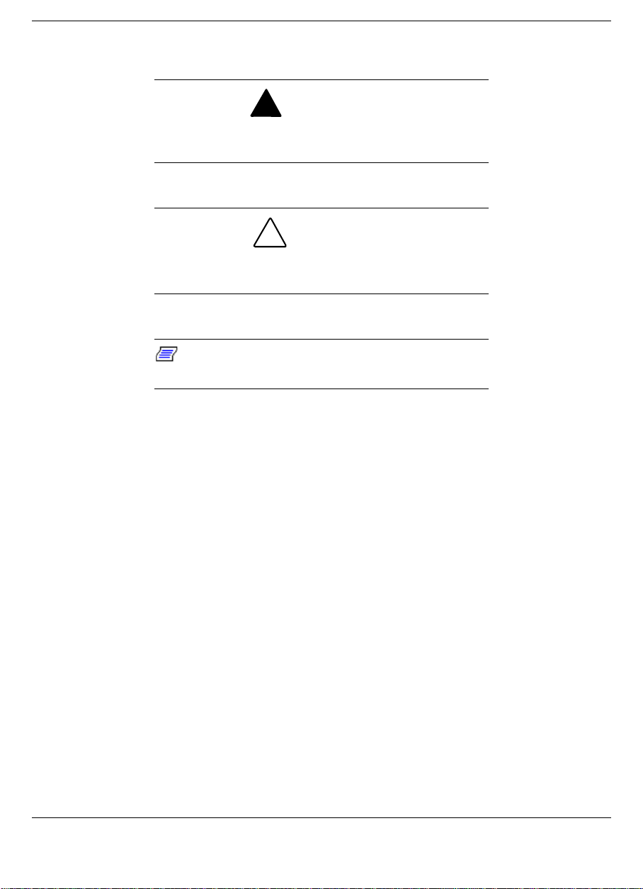
Warnings, cautions, and notes are set up in the following format.
!
WARNING
Warnings alert you to situations that can cause
personal injury or harm.
CAUTION
Cautions indicate situations that can cause damage
to system hardware or software.
Notes give particularly important
Note:
information about the topic being discussed.
Names of keys are printed as they appear on the keyboard, for
!
example, Ctrl, Alt, or Enter.
Text that you must type or keys that you must press are presented in
!
bold type. For example, type dir and press Enter.
Related Documents
See the following documents for information related to the NEC Versa
Dock and NEC Versa operation:
The NEC Versa Dock Quick Setup sheet.
!
Your NEC Versa User’s Guide.
!
The Microsoft Windows and other operating system documentation
!
that came with your NEC Versa.
Manuals and setup instructions for any devices that you are
!
connecting to the NEC Versa Dock.
viii Using This Guide
Page 8

1
Introducing the NEC Versa Dock
Carton Contents
!
NEC Versa Dock Features
!
The Right Environment
!
NEC Versa Dock Care
!
Battery Charging
!
Page 9
The NEC Versa Dock lets you maximize your NEC Versa LX and SX
capabilities without minimizing portability. Connect an external monitor
and keyboard to the ports on the back of the NEC Versa Dock, install
your CD-ROM reader in the optional NEC Versa Dock VersaBay III,
attach your joystick to the MIDI/Game port, and you're ready to work
hard or play! Undock the NEC Versa from the NEC Versa Dock and
you're ready for the road.
This chapter introduces NEC Versa Dock features, guides you to
choosing the correct environment, and describes how to take care of the
unit.
Carton Contents
Unpack and check the contents of the NEC Versa Dock carton.
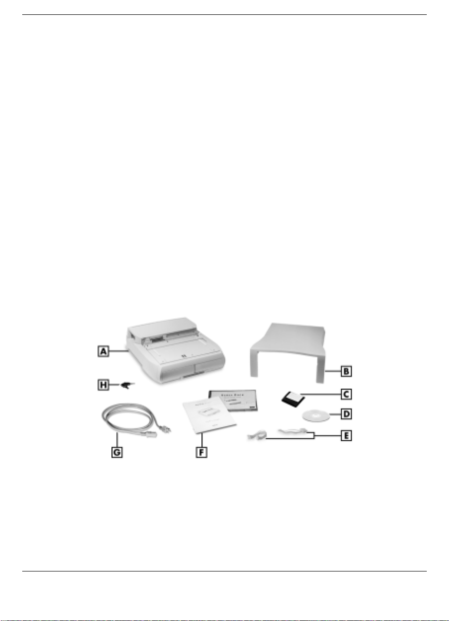
Be sure you have the hardware components shown in the following
figure and that they are in good condition. If anything is damaged or
missing, contact your dealer immediately.
Carton Contents
A
- NEC Versa Dock B - CRT base C - BIOS update diskette
D
- Software Setup CD E - IDE power cables F - User documentation
G
- AC power cable H - NEC Versa Dock keys
1-2 Introducing the NEC Versa Dock
Page 10

NEC Versa Dock — provides many features to expand your NEC
!
Versa capabilities. These features are described in detail in this
chapter.
CRT Base — supports an external monitor that weighs up to 55 lb (25
!
kg).
BIOS update diskettes.
!
NEC Versa Dock Software Setup CD.
!
Two extra power cables for the installation of optional IDE devices.
!
User Documentation — introduces you to the NEC Versa Dock and
!
guides you through initial docking and setup.
AC Power Cable — allows you to connect your NEC Versa Dock to
!
AC power.
Always use the power cable that ships with the NEC Versa Dock. If
you need to replace the cable, follow these standards:
In North America, the cable should be rated for 120 volts (V), 7
amps(A). The plug is a NEMA 5-15P. Use an SVT or SJT 18/3
AWG cable that is less than 15 feet (4.5 m) long. Use connector
type IEC320.
In Europe, the cable should be rated for 230 V (220-240 V), 10A.
The plug is country-specific. Use an H05VV-F or H05VVH2-F
cable that is less than 15 feet (4.5 m) long. Use connector type
EN60320.
NEC Versa Dock Keys.
!
NEC Versa Dock Features
NEC Versa Dock features are found on all sides of the unit. To become
familiar with these features, read each of the following sections.
Introducing the NEC Versa Dock 1-3
Page 11
Front and Top
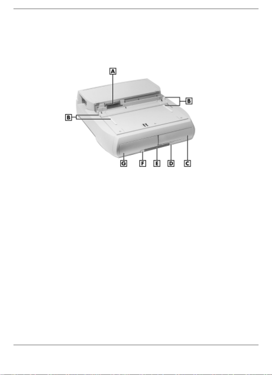
The following figure shows the features found on the front and top of the
NEC Versa Dock. Descriptions of these features follow the figure.
A
- Docking connector B - Docking guides C - Right file bay
D
- Power button E - Status LEDs F - Dock/Undock button
G
- Left file bay
Front and top features
Docking Connector — Fits the expansion port on your NEC Versa to
!
allow for docking.
Docking Guides — Ensure that your NEC Versa is aligned properly
!
for docking. These guides provide positioning for docking with the
monitor stand in place.
Two File Bays — Allows you to install IDE file devices in your NEC
!
Versa Dock.
The left file bay supports any 5.25-inch IDE device (like a tape
drive, hard disk drive, or SuperDisk drive.) It also supports 3.5-
inch IDE devices with a 3.5-inch Universal Installation Kit.
1-4 Introducing the NEC Versa Dock
Page 12
The right file bay is identical to the left file bay, with the added
versatility that it allows you to install the optional VersaBay III
Adapter Kit. With the VersaBay III Adapter kit installed, you can
use any of your VersaBay III options in the file bay.
Power Button — Allows you to power on and off the NEC Versa LX
!
or SX notebook computer while docked on the NEC Versa Dock.
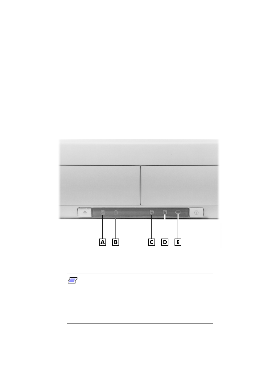
Status LEDs — LEDs on the front of the unit inform you of the
!
docking status, keylock status, IDE drive access, diskette drive
access, and battery charge status (for a battery installed in the optional
VersaBay III Adapter Kit). LEDs are shown in the following figure
and LED states are described after the figure.
Status LEDs
A
- Docking status LED B - Keylock status LED C - IDE access LED
D
- Diskette drive access LED E - Battery charge status LED
Note:
Hot docking and hot undocking is
supported with Plug-and-P lay operating systems,
such as Windows 95. Before hot undocking, the
docking/undocking button must be pressed or you
must select
button.
Eject PC
from the Windows 95 Start
Introducing the NEC Versa Dock 1-5
Page 13

Docking Status – lights as follows:
– Steady Yellow – AC power is on, the keylock switch is in the
Normal position, and the NEC Versa Dock is ready for
docking.
– Steady Green – The NEC Versa is docked on the NEC Versa
Dock and is either powered on or in Standby mode.
– Fast Blinking Amber – A docking or undocking error has
occurred or the docking tray is in the wrong position for the
system.
– Off – AC power is on, the keylock is in the Manual or Locked
position, and either no NEC Versa is docked or the NEC
Versa is docked and powered off.
Keylock Status – Lights as follows:
– Off – No NEC Versa is docked.
– Steady Amber – The NEC Versa is docked but not locked on
the NEC Versa Dock. The key is in either the Normal position
with the notebook turned off, or in the Manual position with
the notebook on or off.
– Steady Yellow – The NEC Versa is locked onto the NEC
Versa Dock through software. The key is in the Normal
position and the NEC Versa is on.
– Steady Green – The NEC Versa is physically locked onto the
NEC Versa Dock. The key is in the Lock position with
notebook power on or off.
IDE Drive Access – lights as follows to indicate access to an IDE
device such as a CD-ROM, hard disk or SuperDisk drive installed
in an NEC Versa Dock file bay, an optional VersaBay III Adapter
Kit, or in the NEC Versa.
– Off – No IDE device is being accessed.
– Green – The NEC Versa is accessing the IDE drive.
1-6 Introducing the NEC Versa Dock
Page 14

Diskette Drive Access – Lights as follows to indicate access to a
floppy disk drive installed in the NEC Versa notebook computer
only.
– Off – No diskette drive is being accessed.
– Green – The NEC Versa is accessing the diskette drive.
Battery Charge Status – Lights as follows to indicate the battery
charge to a secondary battery pack installed in the optional
VersaBay III Adapter Kit.
– Steady Green – The battery installed in the optional VersaBay
III Adapter Kit is being charged. You can charge the battery
whether the NEC Versa Dock is powered on or off or is in
Standby mode. You can also charge the battery in the optional
VersaBay III Adapter Kit when no system is docked in the
NEC Versa Dock. The NEC Versa Dock must be connected to
an AC power source to charge the battery pack.
– Off – The installed battery is fully charged, or no battery is
installed.
Docking/Undocking Button — Initiates the automatic sequence for
!
docking or undocking your system if the keylock is in the normal
position.
Left Side
Features found on the left-hand side of the NEC Versa Dock are shown
in the following figure. Features are described after the figure.
Introducing the NEC Versa Dock 1-7
Page 15
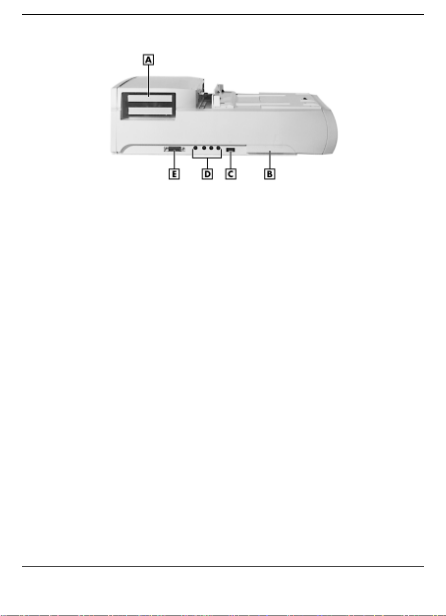
Left side features
A
- PCI external access B - Height lever C - Volume control knob
D
- Audio ports E - MIDI/Game port
PCI External Access — Gives you access to external ports,
!
connectors, switches and indicators on installed PCI cards.
Height Adjustment Lever — Adjusts the height on the docking tray to
!
match the height of your system. To access the lever, pull the door
open by the slot.
Volume Control — Gives you control over the volume of external
!
speakers or headphones attached to the NEC Versa Dock.
Audio Ports — Connects external audio devices including a
!
microphone, headphones, or speakers. You can also connect other
audio devices to use as an output device or input source.
MIDI/Game Port — Supports MIDI/Game devices, such as a joystick
!
or MIDI keyboard.
Right Side
The keylock switch on the right side of the NEC Versa Dock is shown in
the following figure. A description follows the figure.
1-8 Introducing the NEC Versa Dock
Page 16
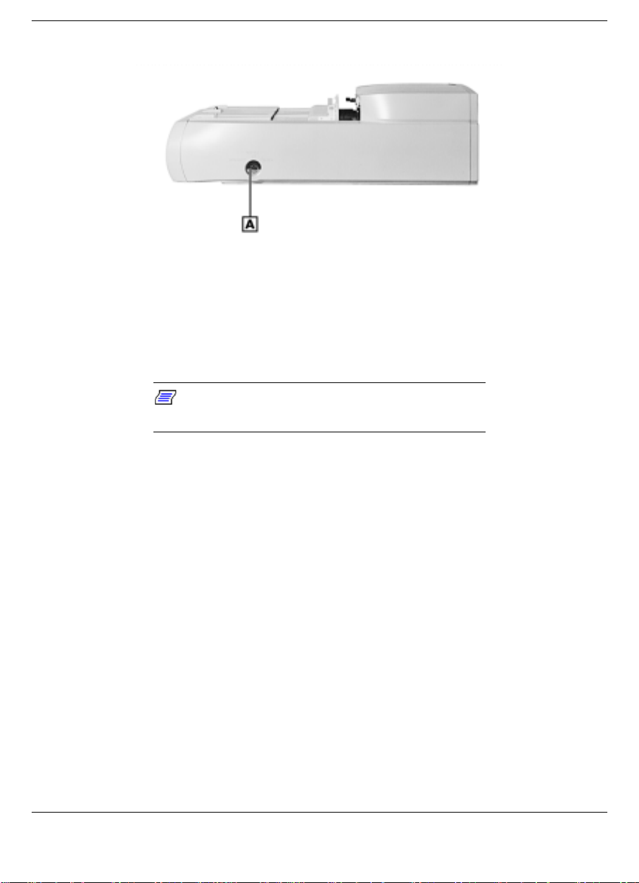
Right side feature
A
- Keylock switch
Keylock switch — Provides three settings that let you control NEC
!
Versa removal. An alarm sounds if someone tries to remove the NEC
Versa while it is locked onto the NEC Versa Dock, even if the NEC
Versa Dock is powered off or is disconnected from AC power.
Note:
Motorized docking is only enabled when
the keylock switch is in the full upright position.
Locked – Prevents the NEC Versa from being removed from the NEC
Versa Dock. You must use the key to unlock the unit before removing
the NEC Versa.
Normal – (Default position). Allows you to motorize dock or undock
the NEC Versa. Set the keylock to this position for normal use. To
prevent electrical damage, manual undocking is not allowed when the
keylock is in this state.
Manual – Allows you to remove the NEC Versa by hand. Use the
unlocked position for emergency undocking only. Otherwise, use the
Normal lock setting for normal use and the Locked setting to
physically secure your system to the NEC Versa Dock.
Introducing the NEC Versa Dock 1-9
Page 17
Back
If no computer is docked and the keylock is in the Locked
position, no one else can use their computer with the NEC Versa
Dock. The key can only be removed from the system while the
keylock is in the Locked position.
Note:
Your NEC Versa Dock comes with two
keys. Be sure to keep these keys in a safe place. If
you lose your keys, you may obtain a new set
through NECC Support Services . You will be
required to provide the key combination found on
the inside of the height lever door in order to get
replacement keys.
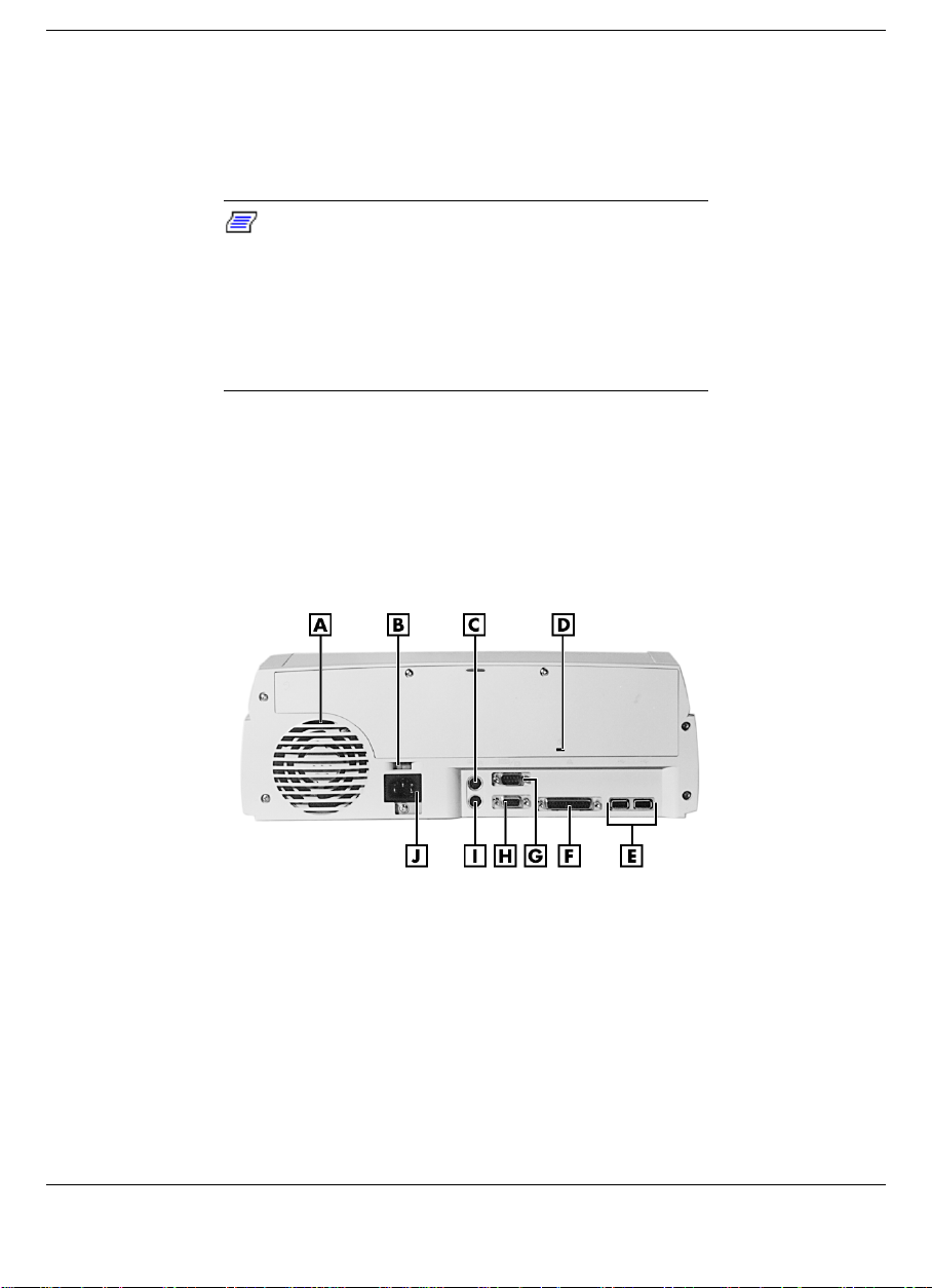
Features on the back of the NEC Versa Dock are shown in the following
figure. Descriptions follow the figure.
Back features
A
- Fan assembly B - Voltage selector switch C - Keyboard port
D
- Kensington lock port E - USB ports F - Parallel port
G
- Serial port H - Monitor port I - Mouse port J - AC power port
Fan Assembly — Provides proper cooling for the power supply that
!
regulates power in the NEC Versa Dock. Keep the fan assembly clear
of obstructions to ensure proper cooling.
Voltage Selector — Allows you to choose from 115 or 230 Volts.
!
1-10 Introducing the NEC Versa Dock
Page 18

PS/2-style Keyboard Port — Allows you to connect an external
!
keyboard to the NEC Versa Dock.
Kensington Lock Port — Allows you to secure your NEC Versa Dock
!
using an optional Kensington Lock.
USB Ports — Allows you to connect Universal Serial Bus devices to
!
the NEC Versa Dock.
Parallel Port — Allows you to connect a parallel device to the NEC
!
Versa Dock.
Serial Port — Allows you to connect a serial device to the NEC Versa
!
Dock.
External Monitor Port — Allows you to connect an external monitor
!
to the NEC Versa Dock. (You may need to press Fn-F3 to get an
image on the external monitor. See your NEC Versa User’s Guide for
function key combinations.)
PS/2-style Mouse Port — Allows you to connect an external mouse to
!
the NEC Versa Dock.
Power Port — Allows you to connect the NEC Versa Dock to AC
!
power.
CAUTION
Always use the power cable that ships with the NEC
Versa Dock or one that is appropriate for your
country. See the cable specifications at the
beginning of this chapter or those listed in Appendix
A, Specifications.
The Right Environment
Before setting up the NEC Versa Dock, find a good location for its use.
Here are some guidelines.
Choose an area close to a wall outlet that is easily accessible.
!
Introducing the NEC Versa Dock 1-11
Page 19

Select a flat, sturdy surface, like a desktop or table, so you have
!
access to the front, back, and sides of the unit.
Choose an area away from extreme temperatures, direct sunlight,
!
excessive dust, vibration, shock or moisture.
Operating Environment
Use the NEC Versa Dock in a location that meets the following
environmental conditions:
Temperature: 41°F to 95°F (5°C to 35°C)
!
Humidity: 20% to 80% (non-condensing)
!
Storage Environment
Store the NEC Versa Dock in a location that meets the following
conditions:
Temperature: –4°F to 122°F (–20°C to 50°C)
!
Humidity: 15% to 85% (non-condensing)
!
NEC Versa Dock Care
With protective measures and proper care, you can keep your NEC
Versa Dock in top operating condition. Follow the measures given next
to maintain your NEC Versa Dock.
Precautions
Follow these precautions when using and storing the NEC Versa Dock.
Do not use or store the NEC Versa Dock in direct sunlight or near
!
radiant heat sources. Heat from these sources can raise the internal
temperature of the unit and damage its parts.
Always use the power cable that came with the NEC Versa Dock or a
!
cable that meets the specifications described at the beginning of this
chapter or in Appendix A, Specifications.
Do not use or store the NEC Versa Dock in dusty environments.
!
1-12 Introducing the NEC Versa Dock
Page 20

Do not use or store the NEC Versa Dock near chemicals.
!
Do not cover the air vents or put anything near enough to them to
!
block air circulation.
Avoid excessive vibration or shock. Dropping the NEC Versa Dock
!
or knocking it over can cause serious damage.
Keep the NEC Versa Dock away from machinery that generates
!
strong electric or magnetic fields.
Do not place heavy objects on the NEC Versa Dock. Make sure the
!
CRT base is in position before placing an external monitor on it. The
CRT base is designed to support an external monitor weighing no
more than 55 pounds (25 kg). Do not place other heavy objects on the
CRT base.
Routine Care
Maintain the condition of your NEC Versa Dock by periodically
following the general procedures listed below.
WARNING
For safety, power off and unplug the NEC Versa
Dock and NEC Versa before cleaning.
Clean the outside of the NEC Versa Dock with a soft clean cloth.
!
Remove stubborn stains with a cloth slightly dampened with a mild
!
detergent. Never use a strong solution or spray cleaner on any part of
the unit.
Check the NEC Versa Dock regularly for loose material, such as
!
paper, books, or magazines, that might block the air vents and prevent
proper air circulation.
Keep food and liquids away from the NEC Versa Dock and NEC
!
Versa.
Introducing the NEC Versa Dock 1-13
Page 21

Battery Charging
The NEC Versa Dock charges the battery installed in your NEC Versa
notebook computer as long as the computer is docked and the NEC
Versa Dock is plugged into AC power.
The NEC Versa Dock charges a battery installed in the optional NEC
VersaBay III Adapter Kit as long as the NEC Versa Dock is plugged into
AC power.
Battery charging occurs whether or not your NEC Versa notebook
computer is powered on.
1-14 Introducing the NEC Versa Dock
Page 22

Docking and Undocking
Connecting the Power Cable
!
Preparing the NEC Versa for Docking
!
Docking the NEC Versa
!
Locking the NEC Versa
!
Undocking the NEC Versa
!
Emergency Undocking
!
2
Page 23

Getting your NEC Versa Dock up and running is easy. This chapter
provides the procedures you need to get started. They include:
Connecting the power cable to AC power and to the NEC Versa
!
Dock.
Preparing the NEC Versa for docking and docking it on the NEC
!
Versa Dock.
Powering on the NEC Versa.
!
This chapter also describes normal and emergency undocking when you
want to use the NEC Versa by itself.
Connecting the Power Cable
Follow the instructions given next in the order presented to get your
NEC Versa and NEC Versa Dock up and running.
Note:
Connect the AC power cable to the NEC
Versa Dock and AC power before docking the
computer.
The power cable that came with the NEC Versa Dock provides power to
both the NEC Versa Dock and the NEC Versa when docked.
Note:
If you need to replace the NEC Versa
Dock power cable, make sure it meets the following
specifications:
! In North America, the cable should be rated for
120 V, 7 A. The plug is a NEMA 5-15P. Use an
SVT or SJT 18/3 AWG cable that is less than 15
feet (4.5 m) long. Use connector type IEC320.
! In Europe, the cable should be rated for 230 V
(220-240 V), 10 A. The plug is country-specific.
Use an H05VV-F or H05VVH2-F cable that is
less than 15 feet (4.5 m) long. The connector
type is EN60320.
2-2 Docking and Undocking
Page 24
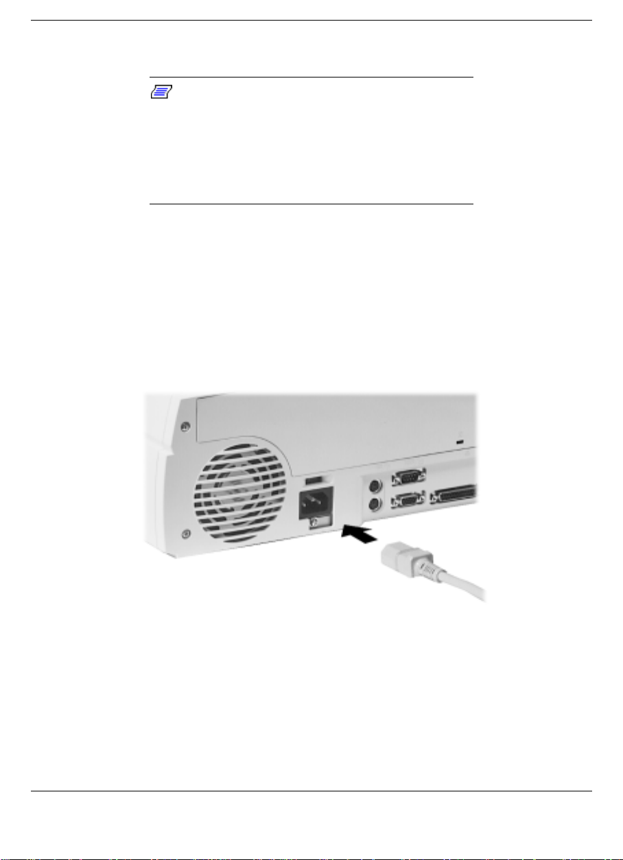
Connect the power cable as follows.
Note:
Ensure that the voltage selection switch
(located on the back of the NEC Versa Dock) is set
correctly for your environment. In the United States,
most wall outlets require you to set the voltage
selection switch to 115 volts. In many European
countries, however, the voltage setting switch
should be set to 230.
1.
Position the NEC Versa Dock on a flat surface close to an AC outlet.
2.
Attach one end of the cable to the AC power port on the NEC Versa
Dock.
3.
Attach the other end to a properly grounded wall outlet.
Connecting the power cable
The NEC Versa Dock is now powered on.
Docking and Undocking 2-3
Page 25
CAUTION
Disconnecting the power cable or experiencing a
power outage while running the NEC Versa Doc k
and NEC Versa can cause the system to suddenly
power off, resulting in a possible loss of data.
Preparing the NEC Versa for Docking
Follow the procedure given below to prepare the NEC Versa for
docking.
1.
Set the NEC Versa power for your system as follows.
If you have an NEC Versa with a Plug and Play operating system
!
such as Windows 95, you can either put your system into
Suspend mode, leave it in full Operation mode for docking, or
you can choose to power off.
If you have a non-Plug and Play operating system such as
!
Windows NT 4.0, turn off the system power before docking.
Note:
Make sure your system is in the
appropriate mode for docking.
2.
If you are running the NEC Versa on AC power, save any open files,
close open applications and disconnect the AC adapter cable from
the NEC Versa.
Note:
Before disconnecting power, save any
open files or close open applications to avoid data
loss.
2-4 Docking and Undocking
Page 26
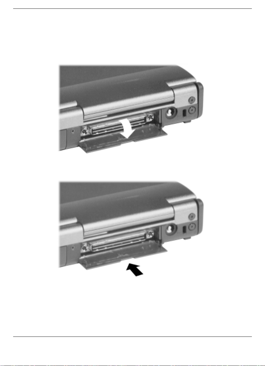
3.
On the back of the NEC Versa, open the expansion port cover and
slide it underneath the expansion port. Check that all other NEC
Versa port covers are closed.
Opening the NEC Versa expansion port cover
Stowing the expansion port cover
4.
Verify that the power cord is plugged into the NEC Versa Dock. (See
“Connecting the Power Cable” for details.)
Docking and Undocking 2-5
Page 27
5.
Ensure that the keylock switch is in the Normal position.
Note:
Motorized docking is only enabled when
the keylock switch is in the full upright position.
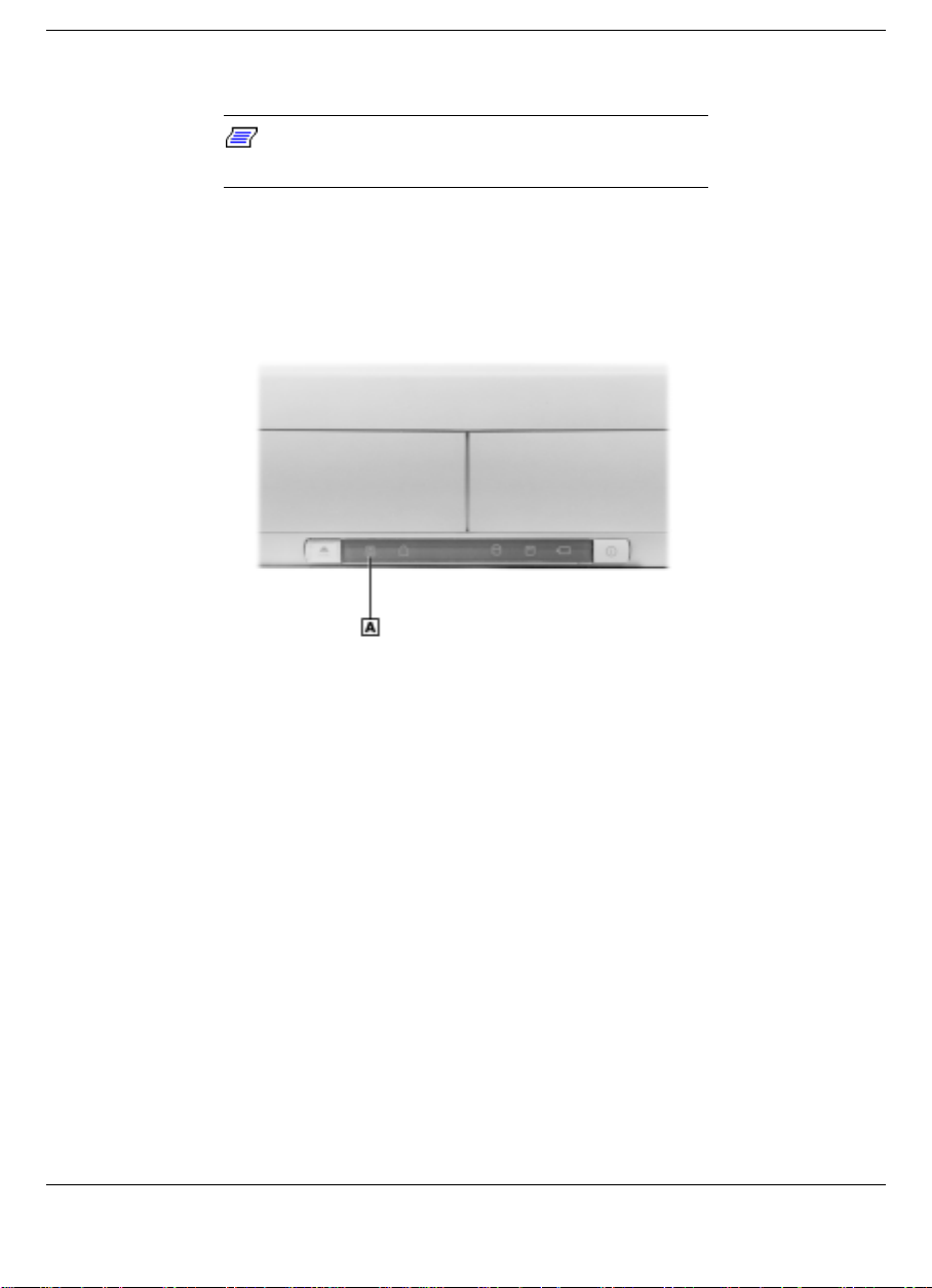
When the Docking Status LED light is steady yellow, the NEC Versa
Dock is ready for motorized docking.
Docking Status LED
A
- Docking status LED
Docking the NEC Versa
You can dock the NEC Versa in one of the following modes (for use
with dual boot systems, see “Dual Booting”):
Cold Docking — with NEC Versa system power off. This method
!
works for all NEC Versa models that support docking.
Warm Docking — with NEC Versa power on, the system in Suspend
!
mode, and NEC Versa Dock power on. This procedure can be used
with NEC Versa systems with Plug-and-Play operating systems, such
as Windows 95.
2-6 Docking and Undocking
Page 28
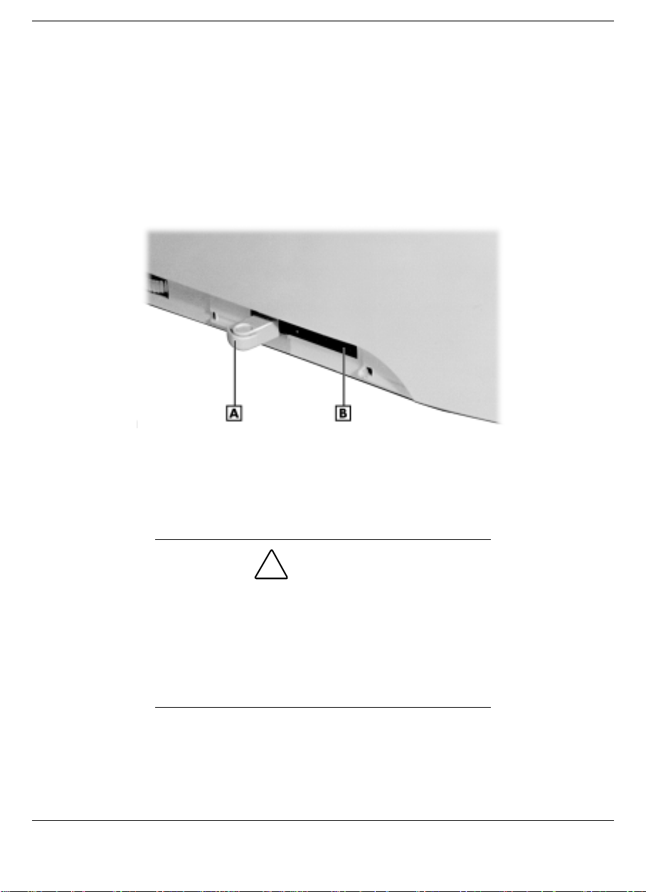
Hot Docking — with NEC Versa power on and the system in full
!
operation mode. This procedure can be used with NEC Versa systems
with a Plug and Play operating system, such as Windows 95.
Use the following steps to dock your NEC Versa.
1.
Locate the height lever on the left side of the unit.
Locating the height lever
A
- Height lever position II B - Height lever position I
2.
Set the height lever on the side of the NEC Versa Dock to match
your system as follows:
CAUTION
It is important that the height lever is set to the
correct height for system docking. The NEC Versa
Dock will not properly dock the NEC Versa if the
height lever is set incorrectly, which may result in
system damage to either the NEC Versa Dock or the
NEC Versa. The Docking LED blinks amber if the
height lever is set incorrec tly.
If you have an NEC Versa LX, set the lever to I by sliding the
!
lever to the front.
Docking and Undocking 2-7
Page 29
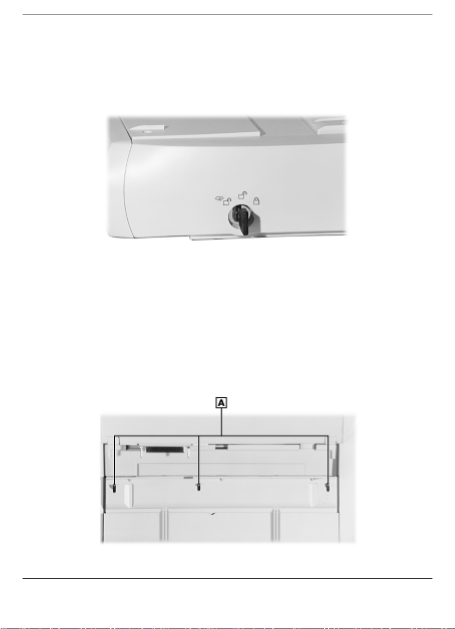
If you have an NEC Versa SX, set the lever to II by sliding the
!
lever to the rear.
3.
Verify that the keylock switch is in the “Normal” position.
Keylock switch in the Normal position
4.
Close the LCD panel on the NEC Versa.
5.
Slide the NEC Versa onto the NEC Versa Dock. Ensure that the
three locking teeth on the NEC Versa Dock fit into the three locking
slots on the bottom of the NEC Versa.
Locating the locking teeth
2-8 Docking and Undocking
Page 30
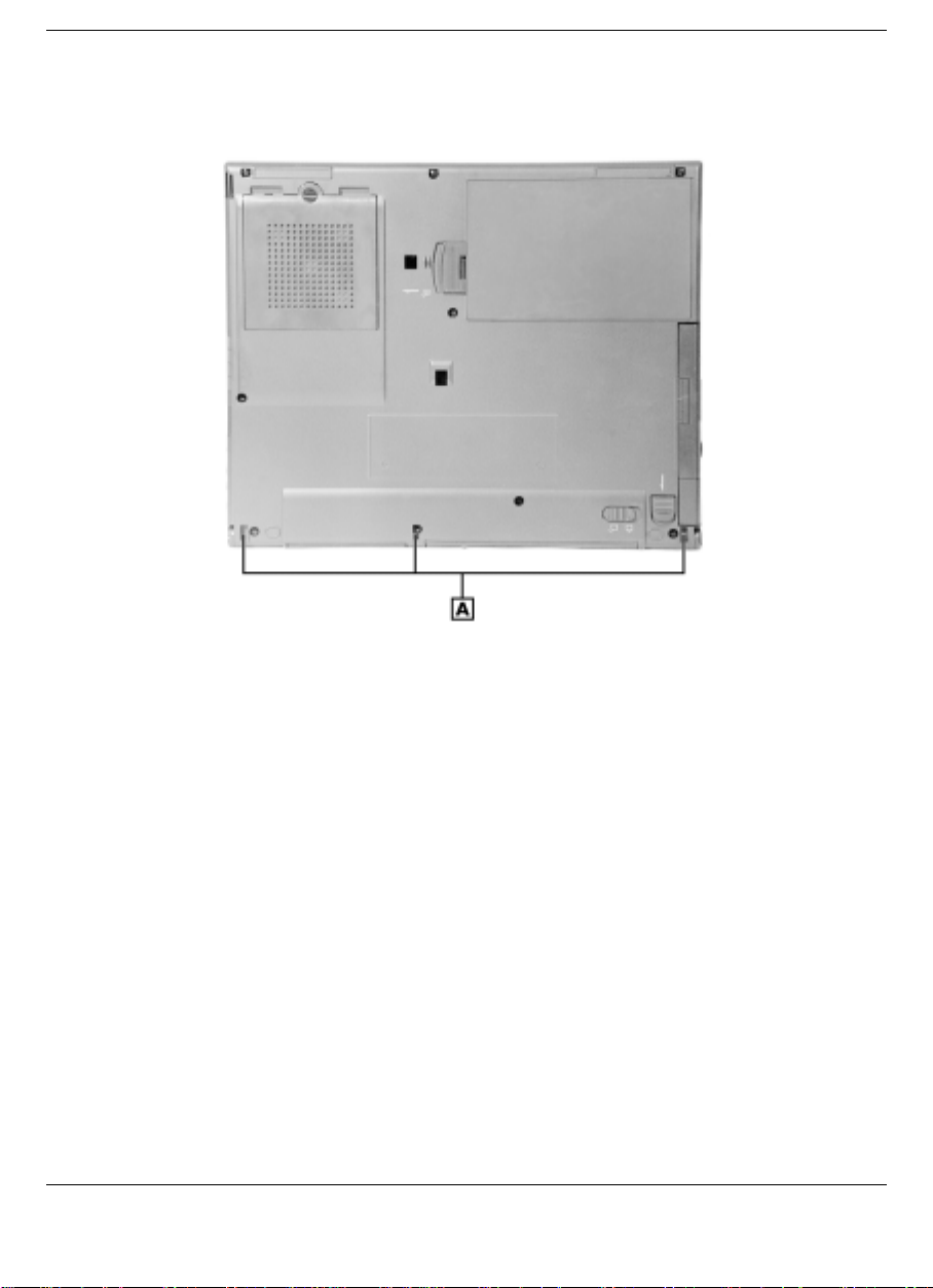
A
- NEC Versa Dock locking teeth
Locating the locking slots
A
- NEC Versa locking slots
Once the notebook is properly seated on the docking teeth, the
docking connector and the expansion port are properly aligned.
Docking and Undocking 2-9
Page 31
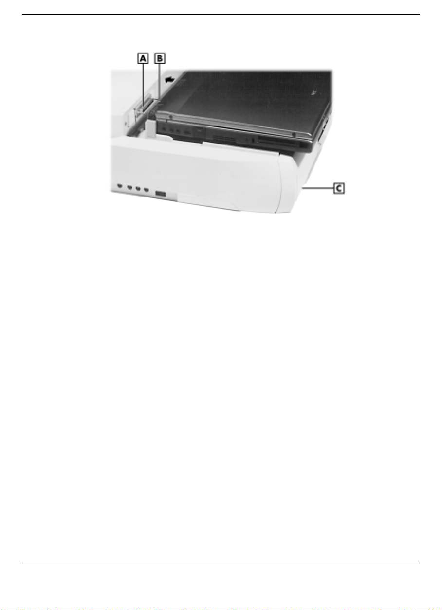
Aligning the NEC Versa with the NEC Versa Dock
A
- Docking connector on the NEC Versa Dock
B
- Docking connector on the NEC Versa (not shown)
C
- Dock/Undock button
6.
Verify that the Docking LED is a steady yellow.
7.
Press the Dock/Undock button on the left of the front panel. The
system automatically docks.
If the system does not automatically dock, ensure that the height
lever is in the correct position for your system and that the system is
correctly seated on the docking tray.
2-10 Docking and Undocking
Page 32
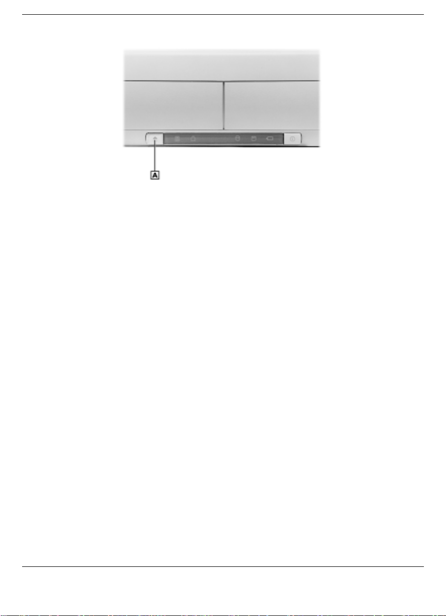
Pressing the Dock/Undock Button
A
- Dock/Undock button
8.
If the Docking Status LED blinks amber, remove the NEC Versa
using the Dock/Undock button, reseat it, and retry docking.
9.
If using the NEC Versa without an external monitor, open the LCD
panel.
10.
If the system was cold docked, press the Power button on the NEC
Versa Dock to power on the NEC Versa.
11.
Verify that the Docking Status LED is steady green, indicating the
NEC Versa is properly docked on the NEC Versa Dock.
Once docked, you can lock the NEC Versa onto the NEC Versa Dock
using the key provided. See the section “Locking the NEC Versa” for
details.
Dual Booting
If you have an NEC Versa that is configured in a dual boot
configuration, such as Windows 95 and Windows NT 4.0 Workstation,
be sure to reboot the system twice to ensure all drives are designated.
Docking and Undocking 2-11
Page 33
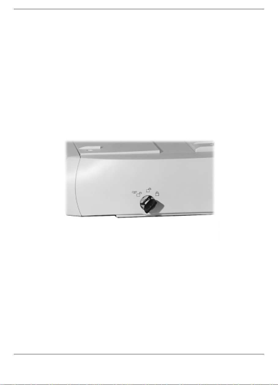
Locking the NEC Versa
Turn the key on the side of the NEC Versa Dock to lock the NEC Versa
onto the NEC Versa Dock. You can choose one of the three following
locking states.
Locked – This setting keeps the NEC Versa from being removed from
!
the NEC Versa Dock. You must use the key to unlock the unit before
removing the NEC Versa. An alarm sounds if someone tries to
remove the NEC Versa while it is locked onto the NEC Versa Dock,
even if the NEC Versa Dock is powered off or is not connected to AC
power.
Turning the keylock switch to Locked
Normal – this default position allows you to motorize dock or undock
!
the NEC Versa. Set the keylock to this position for normal use. To
prevent electrical damage, manual undocking is not allowed when the
keylock is in this state.
2-12 Docking and Undocking
Page 34
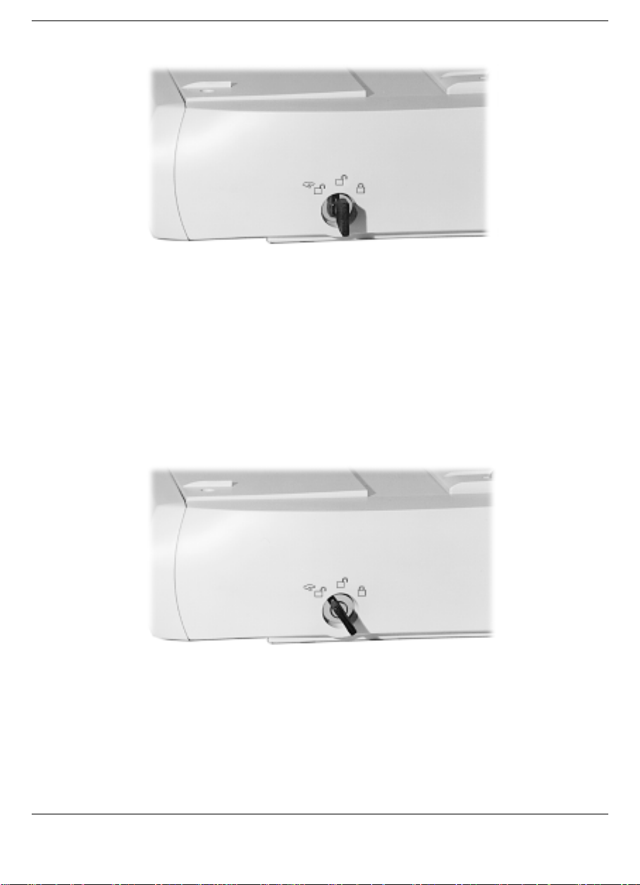
Turning the keylock switch to Normal
Manual – Allows you to remove the NEC Versa by hand. Use the
!
unlocked position for emergency undocking only. Otherwise, use the
Normal lock setting for normal use and the Locked setting to secure
your system to the NEC Versa Dock. The Manual setting requires
manual removal of the computer and resetting the keylock to Locked.
Turning the keylock switch to Manual
If no computer is docked and the keylock is in the Locked position,
no one else can use their computer on the NEC Versa Dock.
Docking and Undocking 2-13
Page 35

Note:
There is an intermediate position or stop
between the Normal and Manual positions. This is
not a valid position for proper operation of the NEC
Versa Dock. Attempting to move the NEC Versa
system with the key in this intermediate position
could result in excessive noise from the NEC Versa
Dock motor. When using the keylock, make sure to
fully turn the key to the desired Normal or Manual
position.
It may be necessary to apply additional pressure
when turning the keylock to the Manual position.
If you move the key from Normal to Manual and back to Normal, you
must move the key to the Locked position and back to Normal to reenable motorized dock and undock.
With the key in the Locked position, do not select the Eject PC option in
the Windows Start menu. Selecting Eject PC causes the system to go
through an undock configuration change therefore disabling all the
docked devices. To correct the configuration, you must undock and
redock the system.
The Keylock Status LED lights as follows to indicate the status of the
NEC Versa Dock.
Off – The NEC Versa is not docked.
!
Steady Amber – The NEC Versa is docked but not locked on the NEC
!
Versa Dock. The key is in either the Normal position with the NEC
Versa turned off, or in the Manual position with the NEC Versa on or
off.
Steady Yellow – The NEC Versa is locked onto the NEC Versa Dock
!
through software. The key is in the Normal position and the NEC
Versa is on.
Steady Green – The NEC Versa is physically locked onto the NEC
!
Versa Dock. The key is in the Lock position with NEC Versa power
on or off.
2-14 Docking and Undocking
Page 36

Undocking the NEC Versa
Undock your NEC Versa as follows.
1.
Check the status of your NEC Versa power:
If you are running a non-Plug and Play operating system such as
Windows NT 4.0, save your files, close any open applications and
exit Windows.
2.
For easier undocking, close the LCD panel. (This is not required, but
is recommended.)
CAUTION
Ensure that all cables connected to the sides of the
NEC Versa are disconnected prior to undocking the
system. Also ensure that CD/DVD drives are closed
and that no diskettes or SuperDisks are extending
from the drive.
3.
Verify that the keylock switch is in the Normal position.
Docking and Undocking 2-15
Page 37
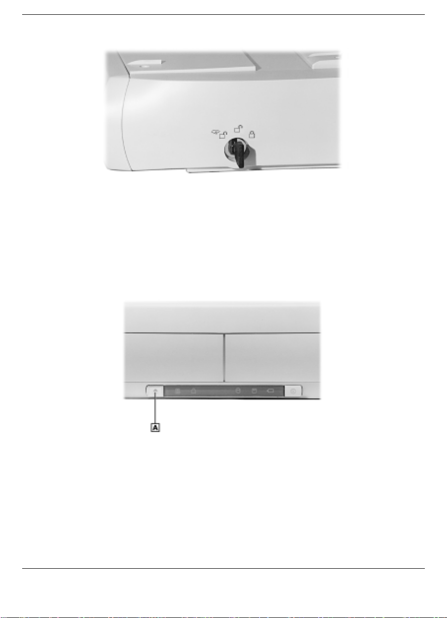
Keylock Switch in the Normal Position
4.
Press the Dock/Undock button on the front of the NEC Versa Dock.
As the docking tray slides forward, the NEC Versa mechanically
ejects from the NEC Versa Dock.
Docking/Undock Button
A
- Dock/Undock button
To use Windows 95 software to undock the NEC Versa, locate and
select the “Eject PC” icon in the Windows 95 Start menu. When you
select this icon, a “Dock Change” window appears.
5.
The NEC Versa Dock automatically ejects the NEC Versa.
2-16 Docking and Undocking
Page 38
Emergency Undocking
To undock your NEC Versa Dock in the event of a power failure or other
emergency, undock the unit as follows.
1.
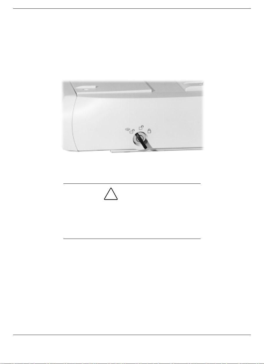
Turn the keylock switch to the Manual position.
Keylock switch in the Manual position
CAUTION
Ensure that all cables connected to the sides of the
NEC Versa are disconnected prior to undocking the
system. Also ensure that CD/DVD drives are closed
and that no diskettes or SuperDisks are extending
from the drive.
2.
Remove the CRT table from the NEC Versa Dock.
3.
Release the NEC Versa from the NEC Versa Dock by firmly pulling
the front of the NEC Versa with equal pressure to the right front and
the left front.
4.
Continue to pull until the NEC Versa is free from the NEC Versa
Dock.
Docking and Undocking 2-17
Page 39
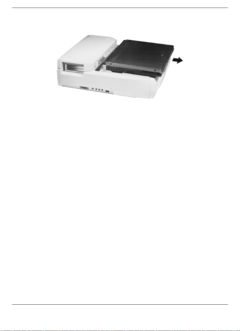
Releasing the NEC Versa from the NEC Versa Dock
2-18 Docking and Undocking
Page 40

Setting Up the Software
Updating the BIOS
!
Installing Drivers
!
Installing the Online User’s Guide
!
3
Page 41

Before docking the NEC Versa in the NEC Versa Dock, be sure to
prepare your NEC Versa notebook computer for use in the NEC Versa
Dock. This involves three procedures.
Flashing the NEC Versa notebook computer’s BIOS, using the
!
correct BIOS Update Diskette for your NEC Versa.
Installing the drivers on the NEC Versa notebook computer, using the
!
NEC Versa Dock Software Setup CD.
Installing the Online User Guide, using the NEC Versa Dock
!
Software Setup CD.
Instructions for installing each of these software utilities can be found in
the following sections.
Updating the BIOS
To update your system BIOS, use only the BIOS update diskette
included with the NEC Versa Dock and be sure to prepare the diskette
before upgrading the BIOS.
Preparing the BIOS Update Diskette
Before using the BIOS update diskette, you must make a backup copy of
it and make the backup diskette BIOS flash ready. Refer to the
readme.txt file on the diskette before using the diskette.
Be sure to make a backup diskette, especially if you
have other NEC Versa LX or SX models. Once the
BIOS Update is complete, the diskette will not
contain BIOS software for other NEC Versa
systems.
Follow these instructions to prepare the BIOS Update Diskette.
Note:
You must have the AC Adapter
connected and use AC power while you perf orm the
BIOS update process.
3-2 Setting Up the Software
CAUTION
Page 42

1.
Start your NEC Versa so it launches your Windows software.
2.
Scan your hard drive for any computer viruses.
3.
Enable the diskette for write access by sliding the write-protect tab to
the write-enabled setting.
4.
Insert the diskette into drive A:.
5.
Press
Start
and access the Run… dialog box. Type
follow the on-screen instructions.(You can also type
DOS prompt.)
The application, Install.bat, copies the DOS system files from your
hard drive onto the BIOS Update Diskette to make it BIOS flash
ready.
The system prompts you when the process is complete.
6.
Scan the BIOS Update Diskette for computer viruses.
The diskette is ready for use.
7.
Shutdown Windows and be sure your system power is off. Follow
the instructions below for performing the actual BIOS update.
Performing the BIOS Update
Use the following procedure to perform the actual BIOS update.
1.
Make sure the NEC Versa is operating under AC power, and that the
power is off. Insert the BIOS Update diskette into diskette drive A.
a:\install
a:\install
and
at the
2.
Power on the computer with the diskette in drive A. The computer
boots and automatically loads the utility. A message similar to the
following appears:
The NEC BIOS Update Utility should not be used to modify the BIOS in a
Versa system which is docked. If your NEC Versa is docked, please exit the
BIOS Update Utility, power down, and undock your NEC Versa before running
the utility. Plug in your power cable before restarting the flash utility.
3.
Press Enter to continue.
Setting Up the Software 3-3
Page 43

The utility checks the currently installed BIOS version and the
diskette’s BIOS version. The Main menu appears.
4.
Use the arrow keys to highlight the “Display BIOS Version” option
on the Main menu. Use this option to check the currently installed
BIOS version and the version of the new replacement BIOS.
5.
Highlight the “Install New BIOS” option and press Enter.
6.
Press Y and then press Enter. The update process begins. Finally, a
message appears telling you to remove the diskette in drive A.
7.
Remove the diskette and press any key to continue. The utility
updates the BIOS.
Power off your computer. The next time you power on your
computer, you will have the latest NEC Versa LX or SX computer
BIOS revision level.
The following message appears also.
Wait…
CMOS Checksum Bad
Press F1 to run Setup
Follow these steps to configure the system’s default settings.
1.
Press F1 to enter the Setup program.
2.
Move the cursor down to highlight Auto Configuration with
Defaults.
Press
Enter
.
3.
The message “Load default configuration settings?” displays.
4.
Enter Y, then press
Press
F10
, then press
5.
You are now ready to resume system operation.
3-4 Setting Up the Software
Enter
Enter
.
to save the default configuration settings.
Page 44

Installing Drivers
The drivers for the NEC Versa Dock can be found on the NEC Versa
Dock Software Setup CD. Refer to the readme.txt file on the CD for
details on driver installation for the NEC Versa Dock.
The Software Setup CD dialog box consists of the following
components.
Selection Tabs — Located just below the title bar, each tab represents
!
a software category.
Description — Located in the bottom portion of the dialog box, the
!
text describes the selected or highlighted software category or driver.
Install — Clicking the Install button installs the selected software.
!
Exit — Clicking the Exit button closes the NEC Versa Dock Software
!
Setup CD dialog box.
Once the NEC Versa Dock Software Setup CD dialog box appears,
follow these steps to install the desired software.
1.
Insert the NEC Versa Dock Software Setup CD into the CD-ROM
reader.
Note:
If you have a combination of two CDROM devices installed in the NEC Versa and the
NEC Versa Dock, be sure you have the NEC Versa
Dock Software Setup CD in the CD-ROM drive that
was installed first and has the lowest assigned drive
letter (such as D:\ or E:\).
2.
From the Start menu, type
3.
Click the Browse button to access the Setup.exe file on the CD.
Run
.
Setting Up the Software 3-5
Page 45

4.
Click the selection tab of your choice.
5.
Click the plus (+) box beside the desired utility to expand the
selection.
6.
Click the Installation selection to activate the Install button.
7.
Click the Install button to install your selection.
8.
Click Exit to close the NEC Versa Dock Software Setup CD dialog
box. Follow the on-screen instructions to install your selection.
9.
Remove the CD from the CD-ROM reader when the installation is
complete.
Installing the Online User’s Guide
The online version of this user’s guide is on the NEC Versa Dock
Software Setup CD. Install the guide onto your hard disk drive as
follows.
Note:
To access the online
User’s Guide
be installed on your system.
, Microsoft Internet Explorer 4.01 must
NEC Versa Dock
1.
Insert the NEC Versa Dock Software Setup CD into the CD-ROM
reader.
Note:
If you have a combination of two CDROM devices installed in the NEC Versa and the
NEC Versa Dock, be sure you have the NEC Versa
Dock Software Setup CD in the CD-ROM drive that
was installed first and has the lowest assigned drive
letter (such as D:\ or E:\).
2.
On the NEC Versa Dock Software Setup application, click on the
NEC Online Documentation tab.
3.
Click on the NEC Versa Dock User’s Guide checkbox.
3-6 Setting Up the Software
Page 46

4.
Click OK to launch the Setup program. The Setup program installs
the online version of this user’s guide.
5.
To access the user’s guide, double click on the NEC Versa Dock
User’s Guide icon that appears on the desktop.
Uninstalling the Online User’s Guide
To uninstall the online NEC Versa Dock User’s Guide from your hard
drive, follow the steps below.
1.
From the Start menu, click on Settings and Control Panel.
2.
From the Control Panel, double click on Add/Remove Programs,
then scroll down to select the NEC Versa Dock Online Guide.
3.
The Uninstall NEC Help Center dialog box appears and allows you
to choose an uninstall method. You can choose either an automatic
uninstall, which removes all NEC Help Center files, or a custom
uninstall, which allows you to choose which files are uninstalled.
Note:
Use caution when using the Custom
Uninstall method. Some of the files may be shared
by other applications and deleting them may affect
other programs.
4.
The Uninstall Wizard guides you through the rest of the uninstall
process.
The NEC Versa Dock User’s Guide and its desktop icon are removed
from your system.
You can reinstall the online user guide at a later time by following the
procedures above in “Installing the Online User’s Guide.”
Setting Up the Software 3-7
Page 47

Installing Options and Connecting Devices
Installing Devices in the File Bays
!
Installing PCI Cards
!
Connecting External Devices
!
4
Page 48

You can optimize your NEC Versa’s functionality by installing options
in the NEC Versa Dock. Options can be installed in the following bays
and slots:
File Bays — two file bays on the front of the NEC Versa Dock give
!
you external access to installed devices.
In the left front file bay, you can install any optional 5.25-inch
IDE device, and with a 3.5-inch Universal Installation Kit, you
can install any 3.5-inch IDE device.
In the right front file bay you can install any optional IDE device
or the optional VersaBay III Adapter Kit. With this Adapter Kit,
you can change this file bay into a VersaBay III slot that lets you
use your VersaBay III devices in the NEC Versa Dock.
Two PCI Board Slots — Two slots let you add two PCI cards to your
!
NEC Versa Dock. One slot supports a full-size card and both slots
support a half-size PCI card.
I/O ports on the sides and back of the NEC Versa Dock let you
!
connect the following external devices:
Parallel device
External monitor
Serial device
PS/2 keyboard and PS/2 mouse (separate ports for each)
USB devices (two ports with hub)
MIDI/Game devices
Audio devices.
This chapter describes how to install devices in the NEC Versa Dock and
how to connect external devices.
4-2 Installing Options and Connecting Devices
Page 49

Installing Devices in the File Bays
The NEC Versa Dock has two 5.25-inch half-height bays for installing
optional devices. The bay located on the right front of the NEC Versa
Dock (the side closest to the keylock), supports the installation of an
optional VersaBay III Adapter Kit. Installing the Adapter Kit transforms
the bay into a VersaBay III. You can then use your optional VersaBay III
devices in the NEC Versa Dock.
Installing devices in the file bays involves the following procedures:
Removing the NEC Versa Dock docking tray, front panel, and cable
!
cover.
Disconnecting the cables from the motherboard.
!
Connecting the cables to the device.
!
Installing the device in the NEC Versa Dock.
!
Reconnecting the cables to the motherboard.
!
Replacing the NEC Versa Dock cable cover, front panel, and docking
!
tray.
Use the instructions in the sections that follow to install an IDE device in
a file bay and to install the optional VersaBay III Adapter Kit.
Removing Trays, Panels, and Covers
Before installing a device in one of the NEC Versa Dock file bays, you
must remove the docking tray, front panel, and cable cover. Do so as
follows:
1.
Unplug the NEC Versa Dock, disconnect any peripheral devices that
are attached, and undock the NEC Versa if it is docked.
2.
Disconnect any external cables that might be attached on an installed
PCI board (such as a network board).
3.
Turn the keylock switch to the Manual position to disengage the
motor mechanism.
Installing Options and Connecting Devices 4-3
Page 50
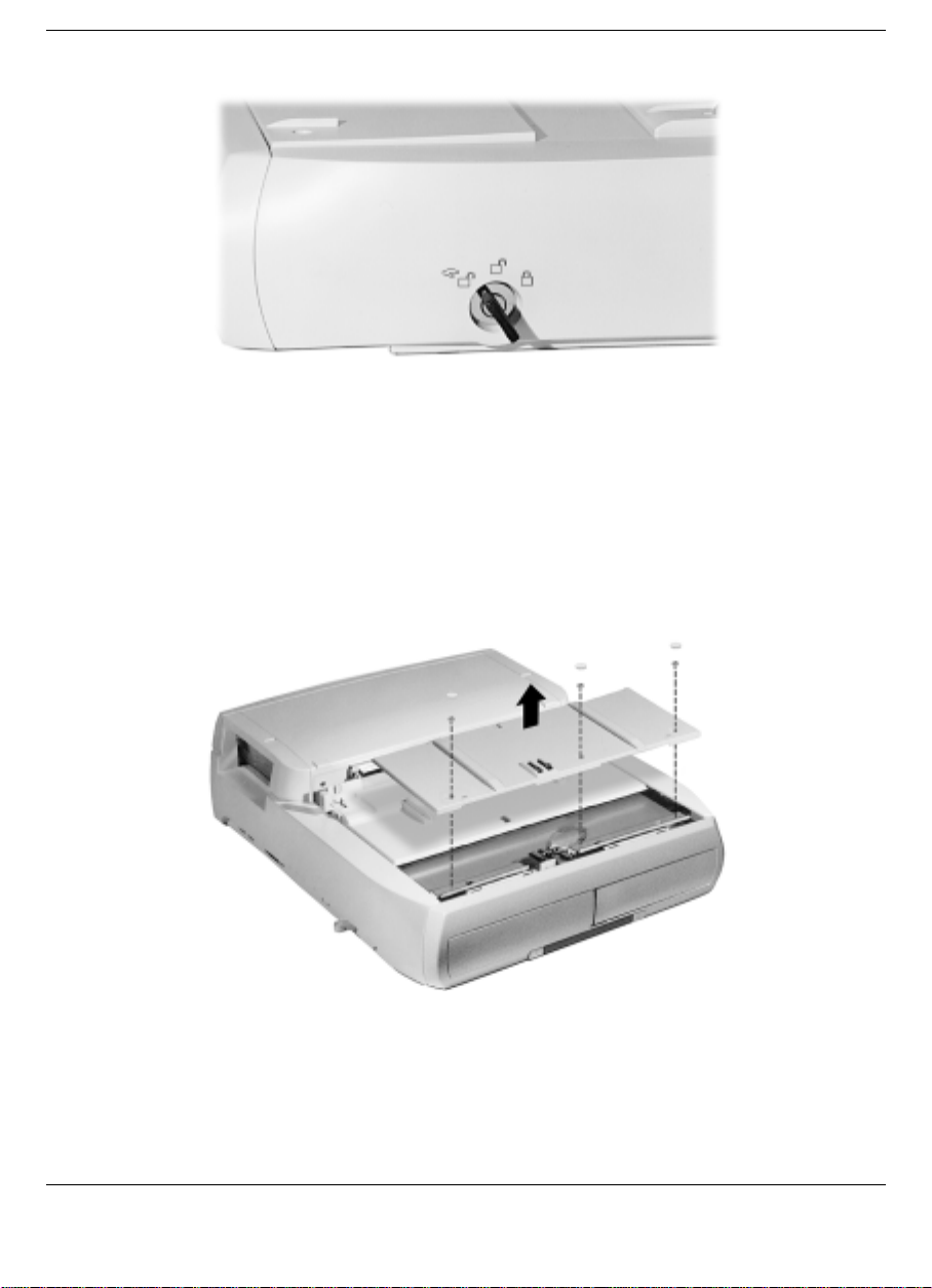
Keylock switch in the Manual position
4.
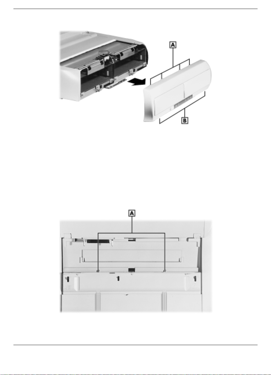
Remove the front part of the docking tray. First locate and remove
the rubber pads securing the three screws, then loosen and remove
the three screws. Lift the docking tray up and off the NEC Versa
Dock.
Removing the docking tray
5.
Remove the front panel from the NEC Versa Dock by removing the
two screws at the bottom and freeing the four tabs from the top of the
panel. Put the screws in a safe place for use when replacing the front
panel.
4-4 Installing Options and Connecting Devices
Page 51
Removing the front panel
A
- Front panel tabs (4) B - Front panel screws (2)
6.
Slide the rear part of the docking tray towards the front of the NEC
Versa Dock until it stops.
7.
Remove the cable cover by locating and removing the two top
screws. Put the screws in a safe place for use when replacing the
cable cover.
A
- Cable cover screws (2)
Locating the cable cover screws
Installing Options and Connecting Devices 4-5
Page 52
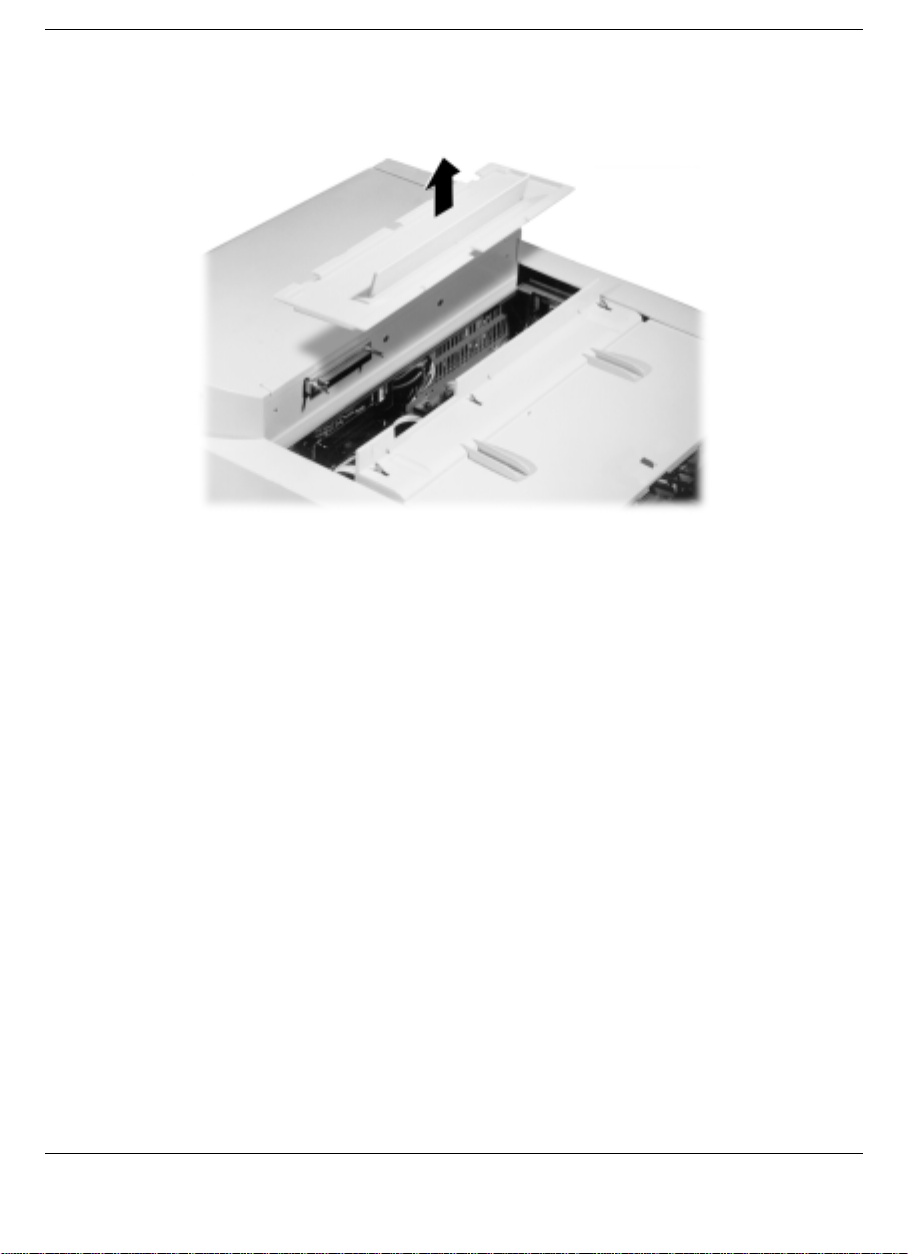
8.
Lift the cable cover up and off the NEC Versa Dock.
Removing the cable cover
You are now ready to disconnect the cables from the motherboard. (See
the instructions in “Disconnecting the Cables from the Motherboard” for
details.)
Disconnecting the Cables from the Motherboard
Disconnect the cables from the motherboard as follows.
1.
Before handling any internal components, discharge static electricity
from yourself and your clothing by touching a nearby metal surface.
2.
See the appropriate figure for the bay that you are using to
disconnect cables from the motherboard.
The following figure shows cable locations in the NEC Versa Dock.
4-6 Installing Options and Connecting Devices
Page 53
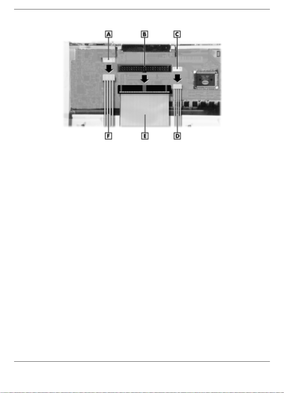
Left-hand bay cables
A
- Power cable port B - IDE signal port C - Audio cable port
D
- Audio cable E - IDE signal cable F - Power cable
Installing Options and Connecting Devices 4-7
Page 54
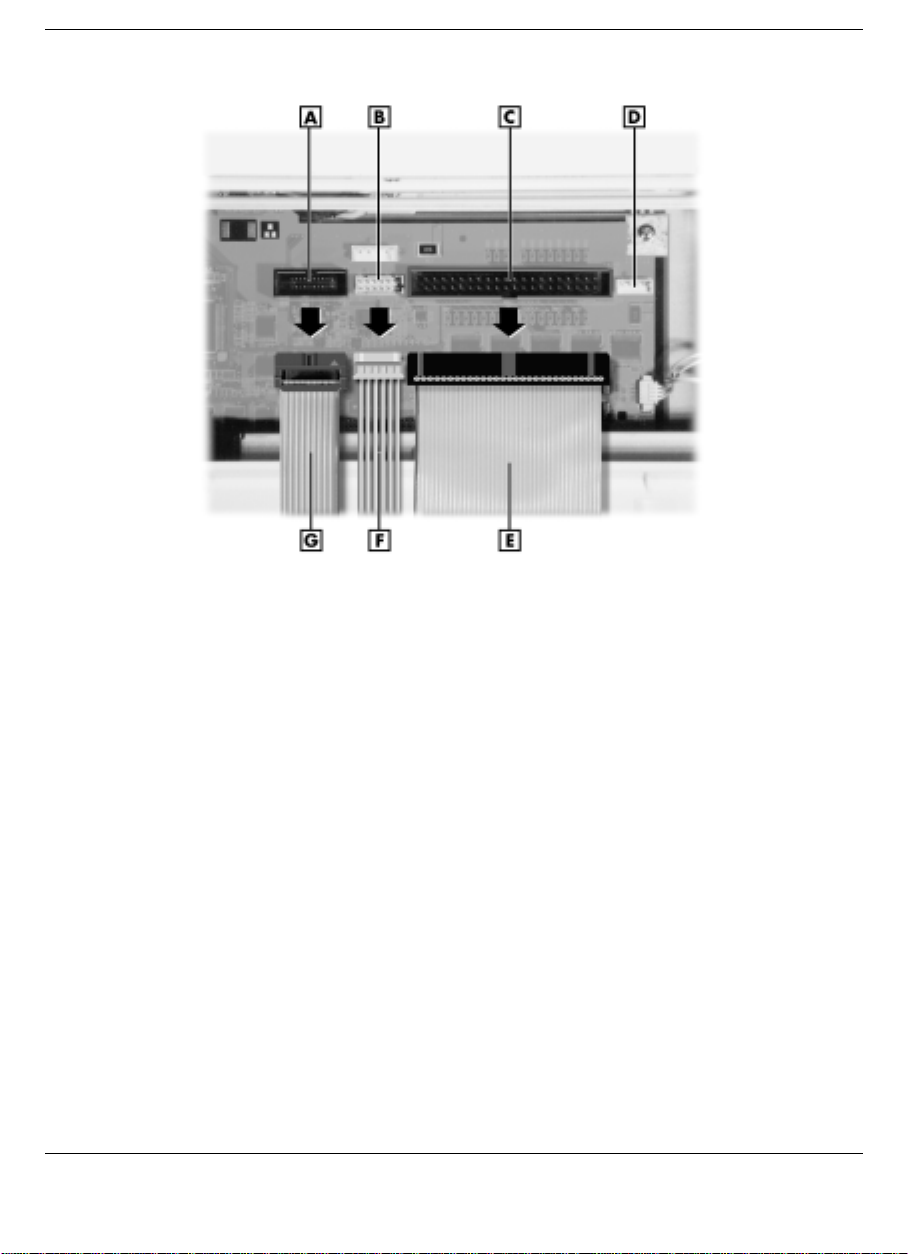
Right-hand bay cables
A
- VersaBay III cable port B - Power cable port C - IDE signal port
D
- Audio port
E -
IDE signal cable F - Power cable G - VersaBay III cable
3.
If you are installing a device in the right-hand file bay and you need
an audio cable, remove the audio cable from behind the left-hand
bay. The NEC Versa Dock comes with only one audio cable.
You are now ready to attach the cables to the appropriate ports on the
back of the device. (See the instructions in “Connecting IDE Device
Cables” for details. If you are installing an optional VersaBay III device,
see the instructions in “Connecting VersaBay III Adapter Kit Cables” for
details.)
Connecting IDE Device Cables
Connect the cables to the IDE device as follows.
1.
Before handling any internal components, discharge static electricity
from yourself and your clothing by touching a nearby metal surface.
4-8 Installing Options and Connecting Devices
Page 55
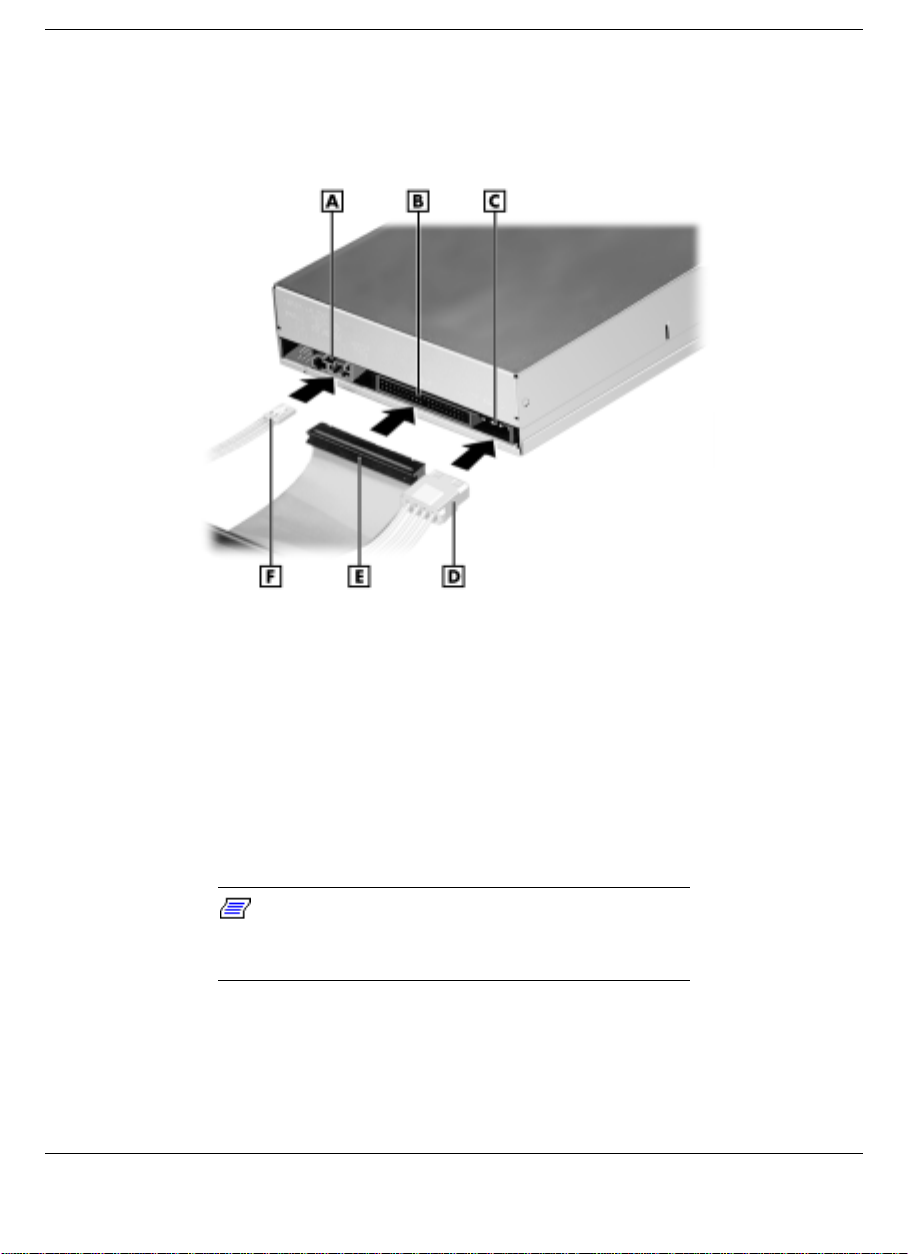
2.
Locate the power cable and IDE signal cable port, and if necessary,
the audio cable port on the back of the IDE device.
Locating and connecting the cables to the IDE device
A
- Audio cable port B - IDE signal cable port
D
- Power cable E - IDE signal cable F- Audio cable
3.
Connect the appropriate power cable, the IDE signal cable, and if
C -
necessary the audio cable to the ports on the back of the IDE device.
The IDE cable must be installed with the red stripe to the left side of
the device.
4.
Ensure that the IDE connector pin is oriented correctly on the IDE
signal cable.
Note:
If the power cable for the device you are
installing uses a small connector, use one of the
cables provided in the accessory kit.
You are now ready to install the IDE device into the file bay. (See the
instructions in “File Bay Installation” for details.)
Installing Options and Connecting Devices 4-9
Power cable port
Page 56

Installing an IDE Hard Drive
When installing an IDE hard drive in the NEC Versa Dock, you should
enter DOS to perform any drive operations such as formatting and
partitioning. The system must be booted to DOS twice. When done,
reboot the system twice to enter Windows 9x or Windows NT 4.0
Workstation.
See the instructions in “File Bay Installation” to install the drive.
Connecting VersaBay III Adapter Kit Cables
Connect the VersaBay III Adapter Kit cables as follows.
Note:
The VersaBay III cable and the power
cable come with the VersaBay III Adapter Kit. They
are not shipped connected to the NEC Versa Dock
motherboard.
1.
Locate the IDE cable port, the VersaBay III signal cable port, and the
VersaBay III power cable port.
4-10 Installing Options and Connecting Devices
Page 57
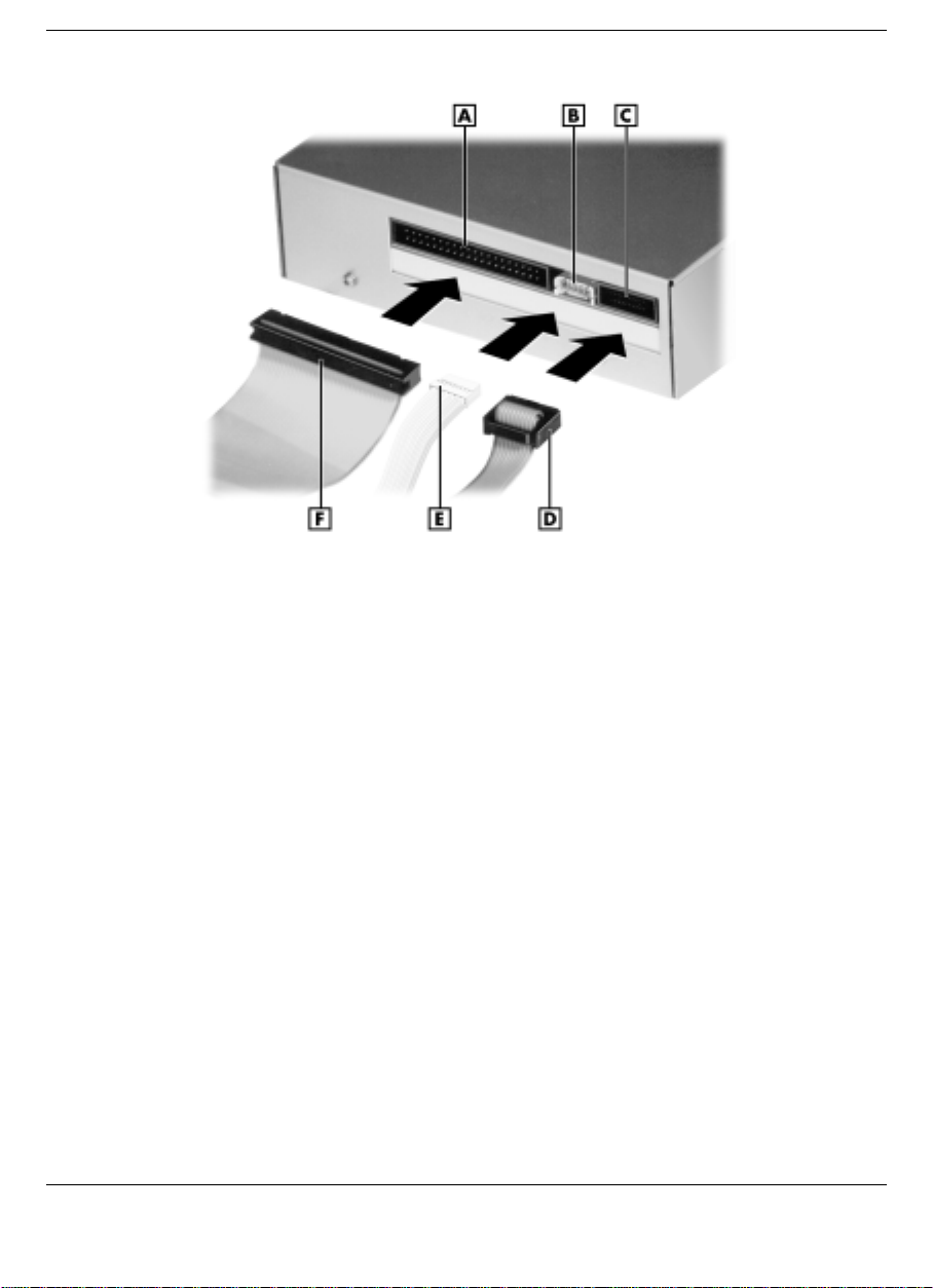
Locating and connecting the cables to the VersaBay III device
A
- IDE signal cable port B - Power cable port C - VersaBay III cable port
D
- VersaBay III cable E - Power cable F - IDE signal cable
2.
Connect the cables to the appropriate ports on the back of the
optional VersaBay III Adapter Kit.
You are now ready to install the optional VersaBay III Adapter Kit into
the file bay. (See the instructions in “File Bay Installation” for details.)
File Bay Installation
Install an IDE device or the optional VersaBay III Adapter Kit in the file
bay as follows.
1.
Before handling any internal components, discharge static electricity
from yourself and your clothing by touching a nearby metal surface.
2.
Remove the NEC Versa Dock docking tray, front panel, and cable
cover. (See the instructions in “Removing Trays, Panels, and
Covers” for details.)
Installing Options and Connecting Devices 4-11
Page 58
3.
Remove the cables from the motherboard. (See the instructions in
“Disconnecting Cables from the Motherboard” for details.)
4.
Attach the cables to the IDE device or the optional VersaBay III
Adapter Kit. (See the instructions in “Connecting IDE Device
Cables” or “Connecting VersaBay III Adapter Kit Cables” for
details.)
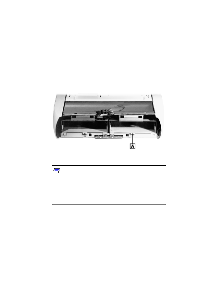
5.
Locate and remove the screw that secures the device bracket in the
bay. (Put the screw in a safe place for use during reassembly.)
Removing the screw securing the device bracket
A
- Device bracket screw
Note:
As an added security feature, the keylock
switch must be in the Manual position before the file
bay brackets can be removed. If the keylock switch
is in the Locked position, the file bay bracket will not
slide forward. This prevents device removal while
the keylock switch is in the Locked position.
6.
Verify that the keylock switch is in the Manual position. The device
bracket will not slide out of the file bay unless the keylock is in the
Manual position.
7.
Slide the device bracket out of the NEC Versa Dock.
4-12 Installing Options and Connecting Devices
Page 59
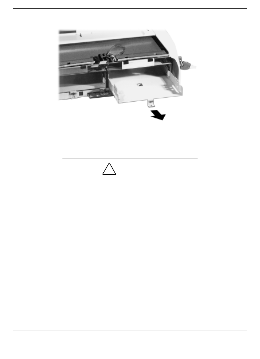
Removing the bracket
8.
Fit the IDE device into the bracket and determine which of the two
front-to-back positions best suits the type of device you are
installing.
CAUTION
Installing a 3.5-inch IDE device in the file bays
without a 3.5-inch Universal Installation Kit can short
circuit and burn out the device. Be sure to install
3.5-inch IDE devices in the file bays using a 3.5-inch
Universal Installation Kit.
9.
Align the screw holes on the side of the device with the screw holes
on the bracket and using the four screws that came with the IDE
device, attach the device to the bracket.
Installing Options and Connecting Devices 4-13
Page 60
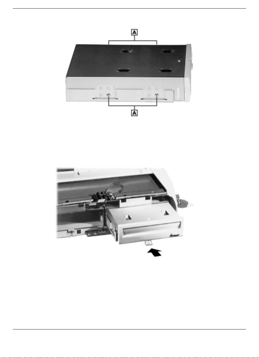
A
- Device bracket screws (4)
10.
Slide the device and bracket into the file bay.
Sliding the device and bracket into the file bay
Attaching the device to the bracket
11.
Secure the screw that attaches the bracket to the NEC Versa Dock.
4-14 Installing Options and Connecting Devices
Page 61
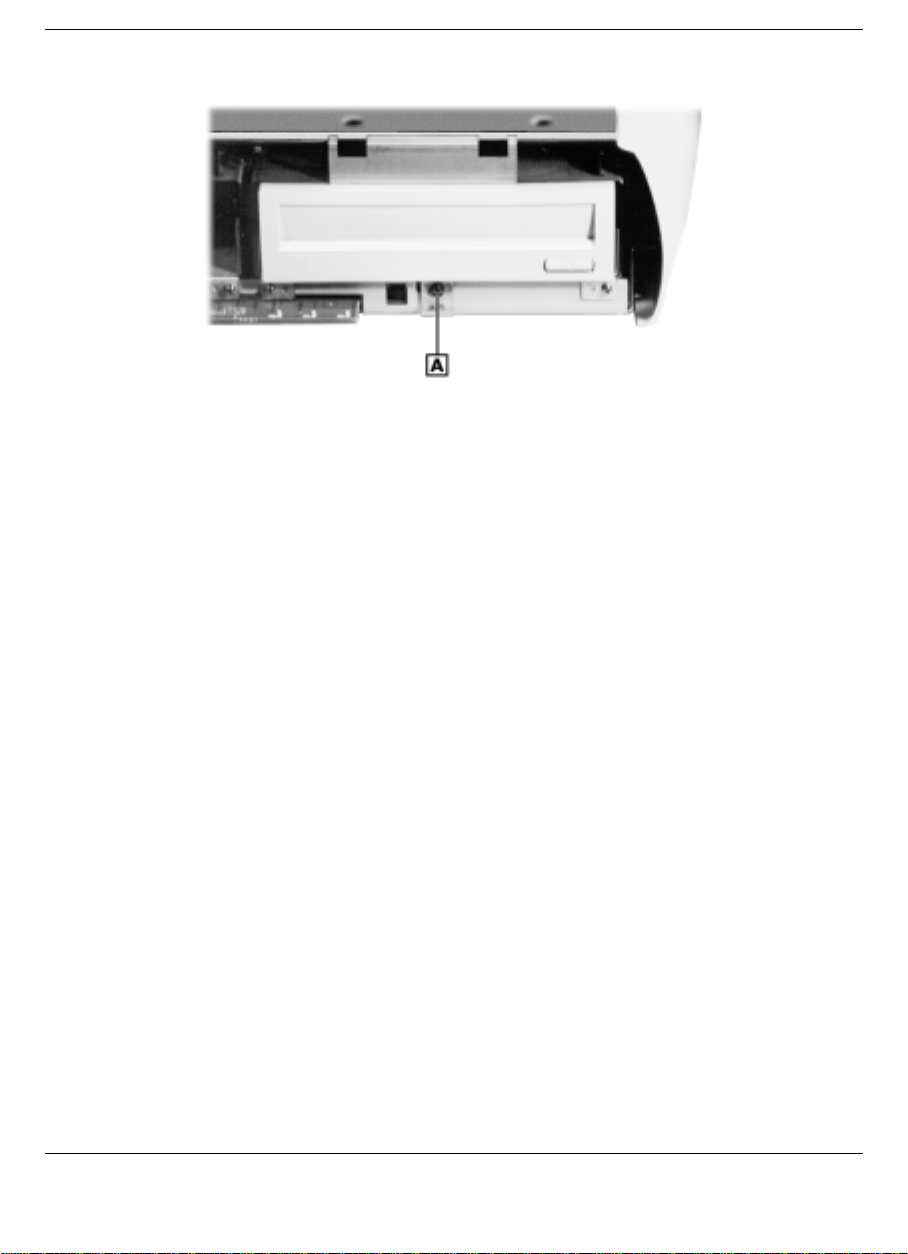
A
- File bay bracket screw
12.
If you have another file bay device to install, do so before replacing
the cable cover, front panel, and docking tray.
You are now ready to reconnect the cables to the motherboard. (See the
instructions in “Reconnecting the Cables to the Motherboard” for
instructions.)
Securing the bracket and device screw
Reconnecting the Cables to the Motherboard
Reconnect the cables to the motherboard as follows.
1.
Before handling any internal components, discharge static electricity
from yourself and your clothing by touching a nearby metal surface.
2.
Locate the power cable slot, IDE signal cable slot, and the audio
cable slot (if necessary) found directly behind the IDE device
installed. If you are installing the optional VersaBay III Adapter Kit,
also locate the VersaBay III cable slot.
Installing Options and Connecting Devices 4-15
Page 62
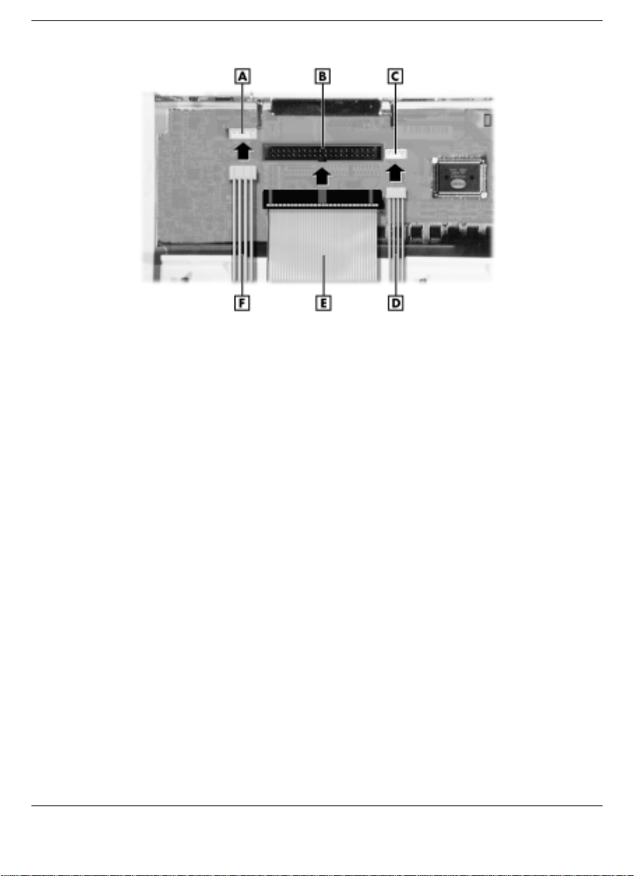
Locating ports and reconnecting cables to the left side of the motherboard
A
- Power cable port B - IDE signal cable port C - Audio ca ble port
D
- Audio cable E - IDE signal cable F - Power cable
4-16 Installing Options and Connecting Devices
Page 63
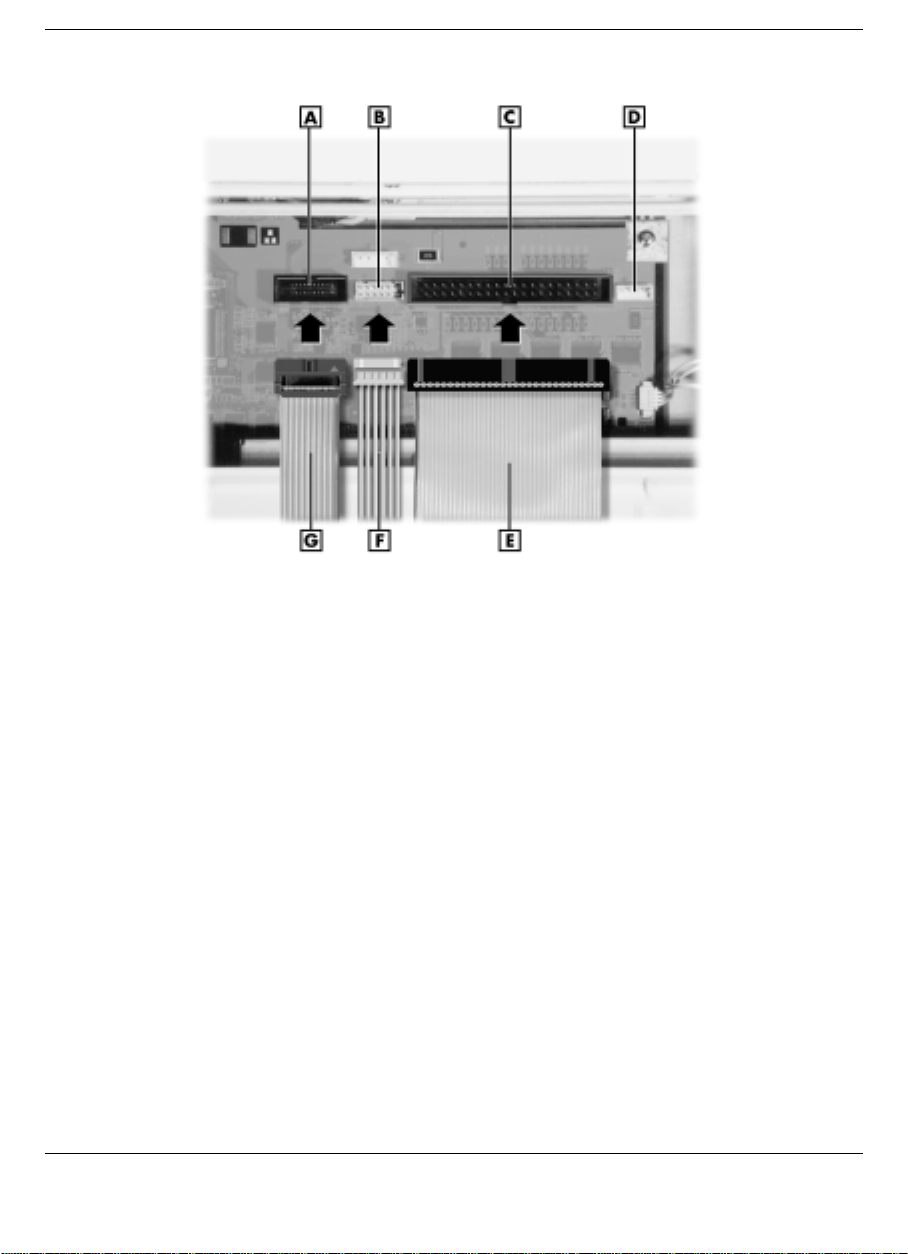
Locating ports and reconnecting cables to the right side of the motherboard
A
- VersaBay III cable port B - Power cable port C - IDE signal cable
D
- Audio Port E - IDE signal cable
F
- Power cable
G
- VersaBay III cable
3.
Reconnect the appropriate power cable and the IDE cable to the
motherboard. Also connect the audio cable or VersaBay III cable, if
necessary, to the motherboard.
You are now ready to replace the NEC Versa Dock cable cover. (See the
instructions in “Replacing Covers, Panels, and Trays” for details.)
Replacing Covers, Panels, and Trays
Replace the NEC Versa Dock cable cover, front panel, and docking tray
as follows.
1.
Align the tabs on the cable cover with the slots.
2.
Lower the cable cover onto the NEC Versa Dock.
Installing Options and Connecting Devices 4-17
Page 64
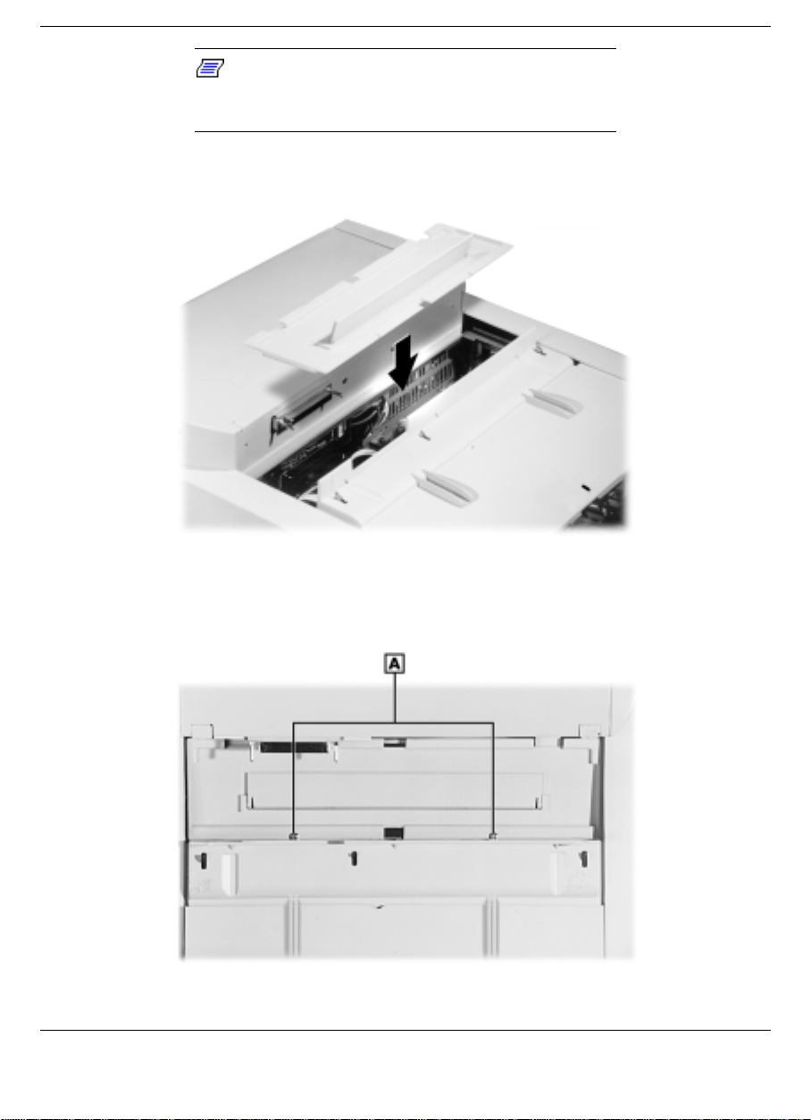
Note:
When replacing the cover make sure the
cover tabs are correctly inserted into the dock before
securing the cov er with the screws.
Lowering the cable cover onto the NEC Versa Dock
3.
Replace the two screws on the top of the cable cover.
Replacing the cable cover screws
A
- Cable cover screws (2)
4-18 Installing Options and Connecting Devices
Page 65
4.
Slide the rear part of the docking tray towards the back of the NEC
Versa Dock until it is seated properly.
Note:
Make sure the docking connector is
aligned with the hole in the docking tra y as you slid e
the docking tray into place.
5.
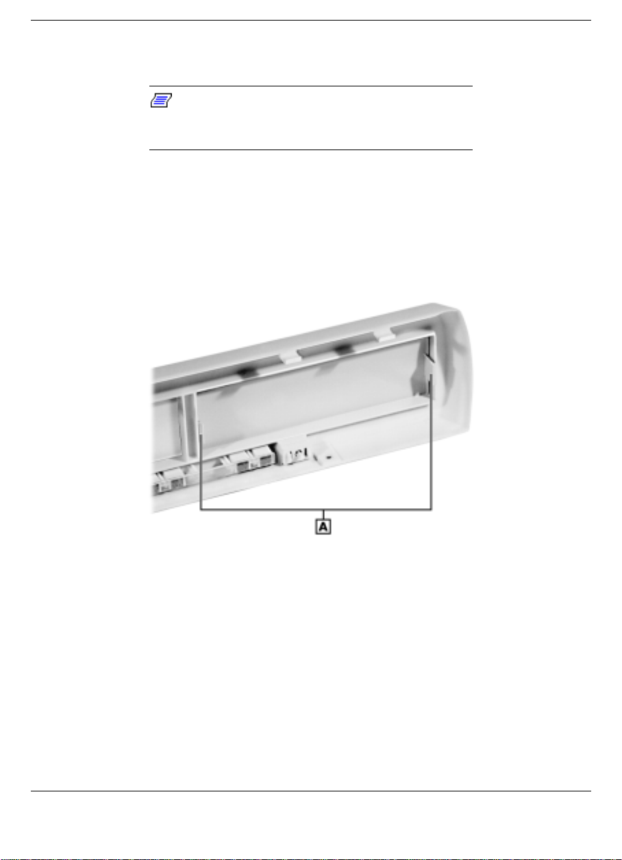
You are now ready to replace the front panel. If the device(s) you
installed require(s) external access, remove the appropriate file bay
cover(s) on the front panel by squeezing the two inside tabs together
and gently pushing the bay cover out of the front panel.
NEC Versa Dock file bay covers
A
- Bay cover t abs (2)
6.
Replace the front panel on the NEC Versa Dock by aligning the four
tabs at the top then replacing the two bottom screws.
Installing Options and Connecting Devices 4-19
Page 66
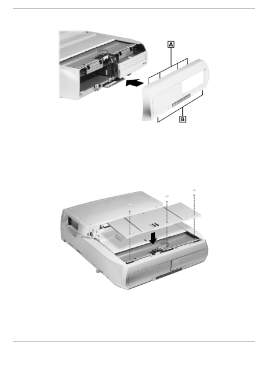
Replacing the front panel
A
- Front panel tabs (4) B - Front panel screws (2)
7.
Replace the front part of the docking tray. Lower the front part of the
docking tray onto the NEC Versa Dock, secure the three screws, then
finish with the three rubber feet.
Replacing the docking tray
4-20 Installing Options and Connecting Devices
Page 67

Installing PC (PCMCIA) Cards
If you plan to use a PC card while your NEC Versa is in the NEC Versa
Dock, it is recommended that you dock the system before installing the
card. The IDE controller inside the NEC Versa Dock uses IRQ11 and if
the card is installed before docking it could cause a resource conflict
with the system.
Installing PCI Cards
Two PCI slots let you add two PCI cards to your NEC Versa Dock. The
top slot supports a full-size PCI card and both slots support a half-size
(or smaller) PCI card. PCI connectors are located in the back of the NEC
Versa Dock. Only the top slot supports a full-size card.
The optional NEC 3Com Fast EtherLink LX provides a networking
solution for the NEC Versa Dock for systems running Windows 95 and
Windows NT 4.0. This PCI card supports Wake on LAN technology,
which allows you to manage your networked systems remotely.
For installation and configuration information, see the documentation
that came with the NEC 3Com Fast EtherLink LX.
Follow these steps to install a PCI card in the NEC Versa Dock.
1.
Unplug the NEC Versa Dock before installing or removing any PCI
cards.
2.
Remove the back cover by locating and removing the two screws.
3.
Put the screws in a safe place for use when replacing the cover.
Installing Options and Connecting Devices 4-21
Page 68
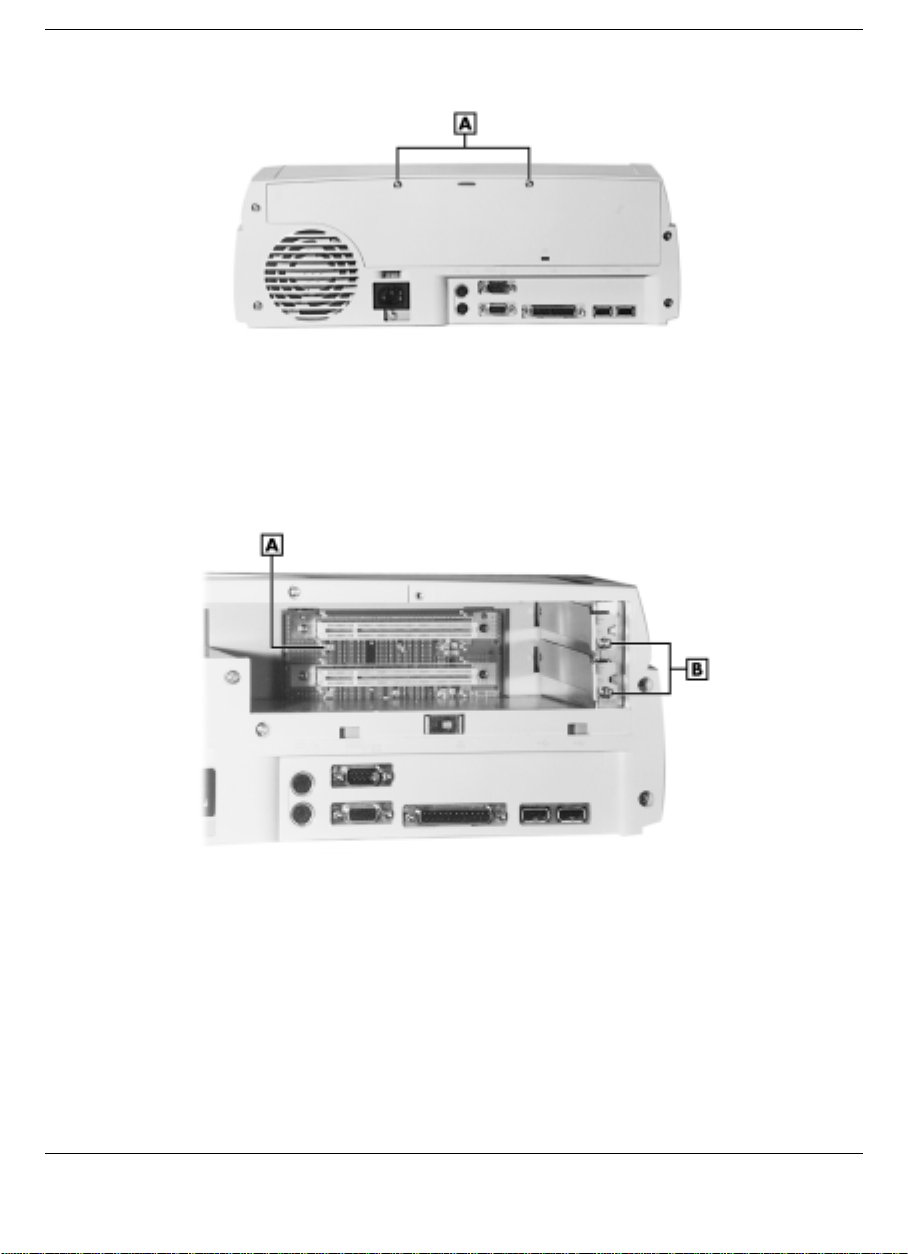
Locating and Removing the Back Cover Screws
A
- Back cover screws (2)
4.
Locate and remove the slot cover screw. If you are installing a fullsize card, remove the top PCI slot cover screw and the slot cover.
Removing the slot cover screw
A
- Wake-On LAN connector B - Slot cover screws
5.
Align the PCI card with the slot connector.
4-22 Installing Options and Connecting Devices
Page 69
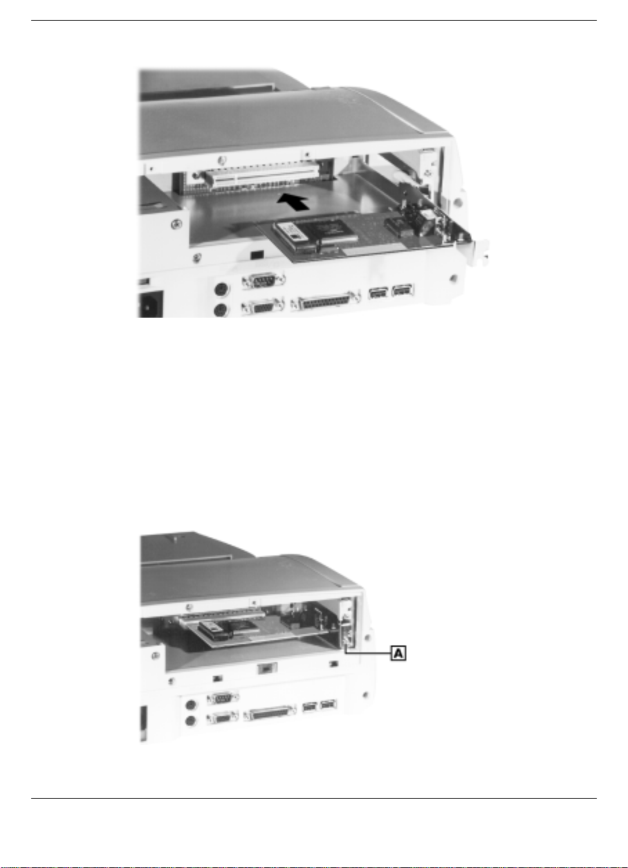
Inserting the card
6.
Firmly push against the card until the connection is secure. If internal
SCSI devices are being installed, the device cable(s) must be routed
from the PCI card to the file bays. Feed one end of the cable through
the left side of the back of the unit and gently pull it toward to the
back of the SCSI device. Connect to the SCSI device and the card.
7.
A
- Slot cover screw
Replace the slot cover screw to secure the card.
Securing the card
Installing Options and Connecting Devices 4-23
Page 70

8.
Attach device cables to the installed PCI card.
9.
Replace the back cover of the NEC Versa Dock and secure it with
the two screws.
10.
Reconnect the power cable.
Using PCI Cards
When using PCI cards, it is important that you check that the device is
not enabled in all configurations in the Device Manager. You can check
this by using the following procedure.
1.
After installing the PCI card and drivers, click Start, Settings, and
Control Panel.
2.
Double click System.
3.
Click the Device Manager tab. Select the card type from the list,
highlight the PCI card, and click Properties.
4.
Under the General tab, make sure the box “Exists in all hardware
profiles” is not checked. If it is checked, remove the check.
5.
For more information on using multiple configurations in Windows
95, search for “hardware profiles” in Windows Help.
Connecting External Devices
Review the following sections for instructions on connecting external
devices to the NEC Versa Dock.
Serial Device
The NEC Versa Dock is equipped with an industry standard 9-pin RS232C serial port. Use this port to install a serial device such as a printer
or an external modem.
Note:
When you connect a printer, be sure to
install the appropriate printer driver through the
Windows Control Panel.
4-24 Installing Options and Connecting Devices
Page 71
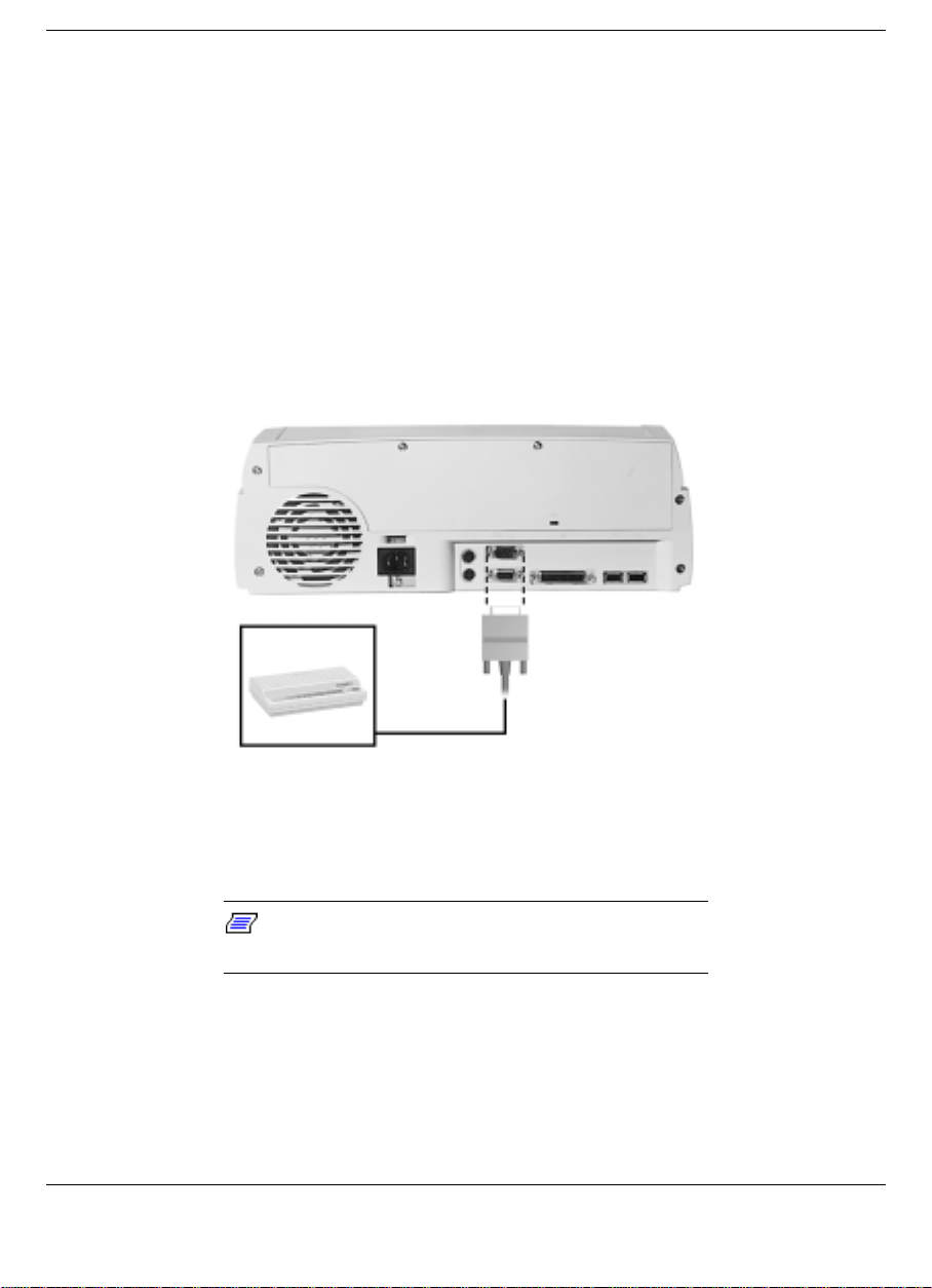
Follow these steps to connect a serial device to your NEC Versa Dock.
1.
Check that both the NEC Versa and the device power are off.
2.
Align and connect the 9-pin connector to the serial port on the NEC
Versa Dock.
3.
Secure the connection with the screws provided on the cable.
4.
Align and connect the other end of the cable to the appropriate port
on the device, if necessary. Secure the connections with the screws
provided, if necessary.
Connecting a serial device
5.
Connect the power cable to the device and a properly grounded wall
outlet.
6.
Turn on the power to the external device.
Note:
Make sure your printer is online before
trying to print. See the printer guide for instructions.
7.
Turn on the power to the NEC Versa Dock.
Installing Options and Connecting Devices 4-25
Page 72
External Keyboard and Mouse
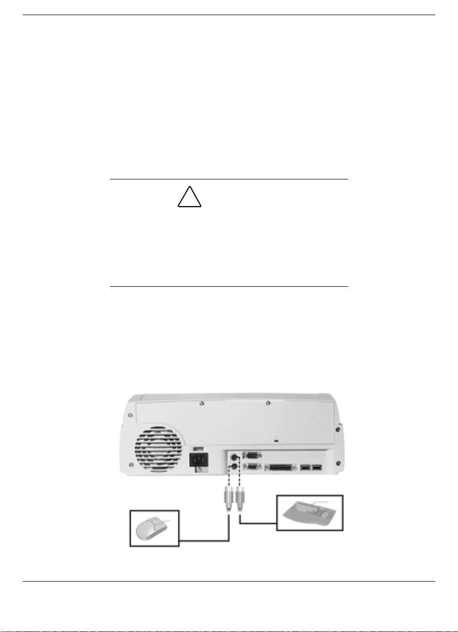
You can connect a full-size PS/2-style keyboard and/or PS/2-style mouse
to your NEC Versa Dock. You can continue to use the system keyboard
or VersaGlide while an external keyboard or mouse is connected.
Follow these steps to connect an external keyboard or mouse to your
system.
1.
For non-Plug and Play operating systems such as Windows NT 4.0,
power off the NEC Versa.
CAUTION:
For non-Plug and Play operating systems such as
Windows NT 4.0, make sure the NEC Versa is
powered off whenever you add or remove an
external keyboard or mouse. Connecting an external
keyboard or mouse to the system in Operation mode
can cause the system or device to malfunction.
2.
Connect the keyboard cable connector to the keyboard port on the
NEC Versa Dock. Connect the mouse cable connector to the mouse
port on the NEC Versa Dock.
Connecting an external keyboard and mouse
4-26 Installing Options and Connecting Devices
Page 73
3.
For non-Plug and Play operating systems such as Windows NT 4.0,
power on the system. The system immediately recognizes the
keyboard or mouse.
you can use both the built-in keyboard and external
keyboard simultaneously. (Only the numeric keypad
on the external keyboard works in this case.)
External Monitor
The NEC Versa Dock is equipped with an industry standard 15-pin VGA
monitor connector. The monitor connector supports a video graphics
array of various resolutions. See the monitor’s user’s guide for details.
Follow these steps to connect an external monitor to the NEC Versa
Dock.
1.
Check that the docked NEC Versa is powered off and the monitor
power switch is turned off.
off while the monitor is being connected or the
system does not recognize the monitor type.
Note:
After you connect an external keyboard,
Note:
The docked NEC Versa must be powered
2.
Position the monitor as follows:
To use the monitor without the monitor stand, simply place the
!
monitor on a flat surface next to the NEC Versa Dock.
To use the monitor stand
!
The monitor stand supports a monitor weighing up
to 55 pounds. Do not place a heavier monitor on the
stand as the heavier monitor may damage the
stand.
Installing Options and Connecting Devices 4-27
CAUTION
Page 74
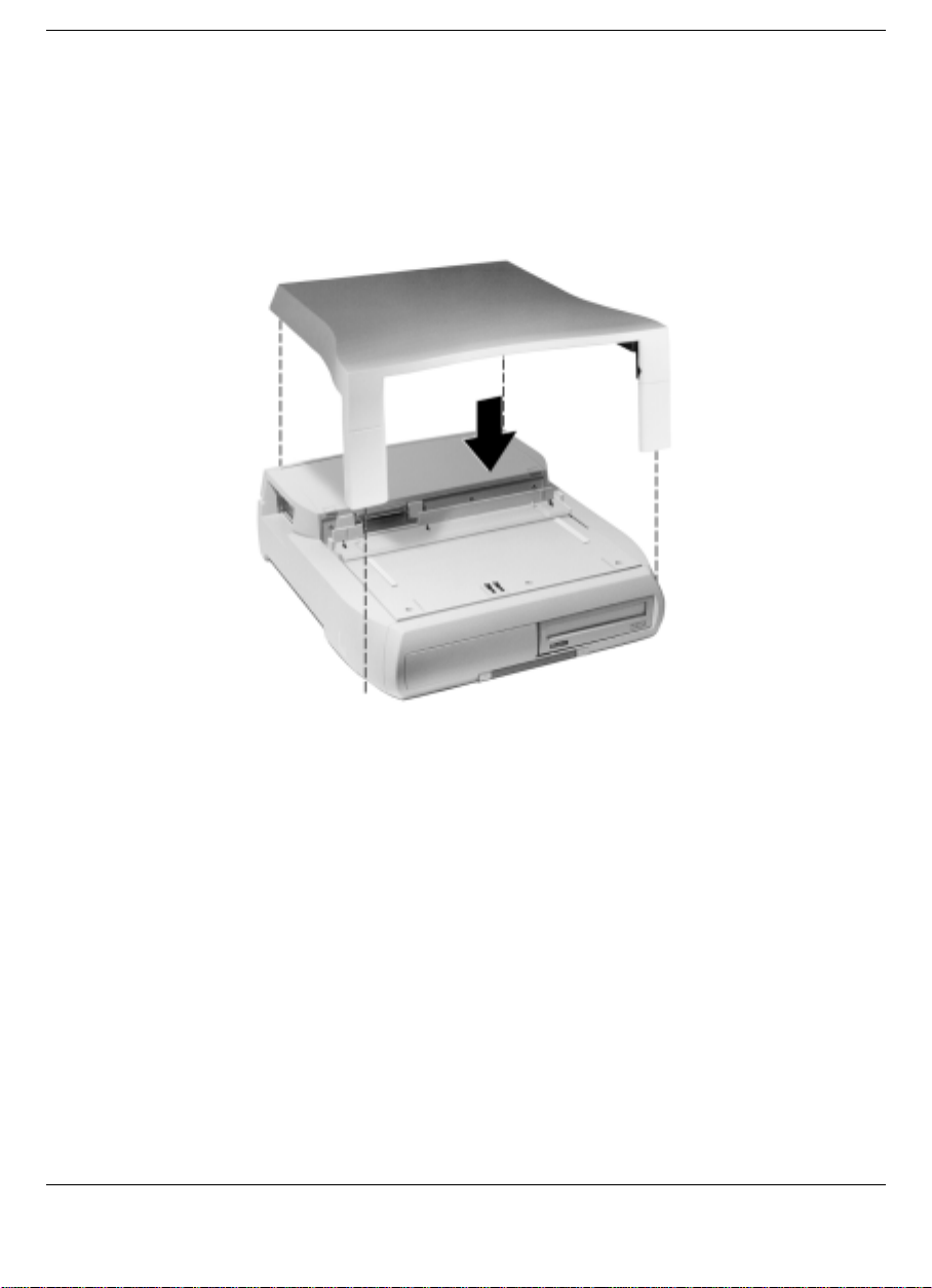
Close the LCD panel on the NEC Versa.
Lower the monitor stand onto the NEC Versa Dock.
Carefully center the external monitor on the monitor base.
Lowering the monitor base into place
3.
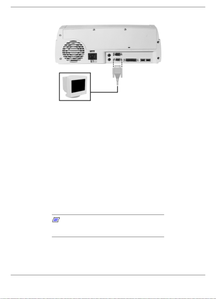
Attach the 15-pin cable connector to the monitor port on the NEC
Versa Dock.
4.
Secure the cable connection with the screws provided on the cable.
4-28 Installing Options and Connecting Devices
Page 75
Connecting a monitor cable
5.
Connect the monitor power cable and plug it into a properly
grounded wall outlet.
6.
Follow any setup instructions in the monitor’s user’s guide.
7.
Power on the monitor.
8.
Power on the NEC Versa.
Press Fn-F3 to toggle between the LCD, CRT, simultaneous CRT/LCD
display, and TV Out (on systems that support TV Out).
Parallel Devices
To install a parallel device such as a printer, you need a cable with a
male 25-pin connector for the system and, for most parallel printers, a
Centronics®-compatible 36-pin connector.
install the appropriate printer driver through the
Windows Control Panel.
Connect a parallel device to the NEC Versa Dock as follows.
1.
Check that both NEC Versa and the parallel device power are off.
Note:
When you connect a printer, be sure to
Installing Options and Connecting Devices 4-29
Page 76
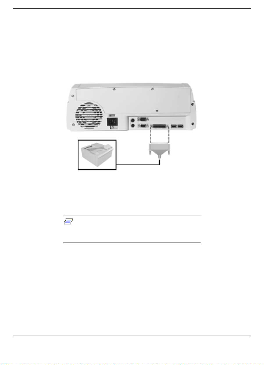
2.
Align and connect the 25-pin parallel cable connector to the parallel
port on the NEC Versa Dock. Secure the cable with the screws
provided.
3.
Align and connect the other end of the cable to the parallel port on
the device. Lock the connector clips.
Connecting a parallel printer
4.
Connect the power cable to the device and a properly grounded wall
outlet.
5.
Turn on power to the system and the device.
Note:
Check that the device is online before you
try to use it. See the instructions that came with the
device for more information.
USB Devices
The NEC Versa Dock lets you take advantage of the latest USB
technology available to Windows 95 users.
Plug USB devices into your Windows 95 system as follows.
4-30 Installing Options and Connecting Devices
Page 77
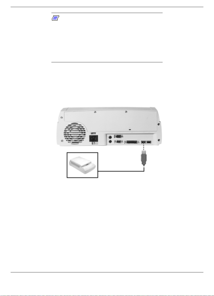
Note:
The USB hub on both the NEC Versa and
the NEC Versa Dock are active at the same time.
You can connect USB devices to all three ports to
further increase system connectivity.
Any external USB hubs you wish to connect to the
NEC Versa Dock must have an external power
supply.
1.
Locate the USB ports on the back of the NEC Versa Dock.
2.
Plug in the USB connector.
Connecting a USB device
MIDI/Game Devices
The MIDI/Game port lets you attach a joystick or MIDI device to your
NEC Versa Dock. Connect a joystick or MIDI device as follows:
1.
Check that both the NEC Versa and the device power are off.
2.
Locate the MIDI/Game port on the side of the NEC Versa Dock.
3.
Plug in the joystick or MIDI device and power on the MIDI device
and NEC Versa Dock.
Installing Options and Connecting Devices 4-31
Page 78
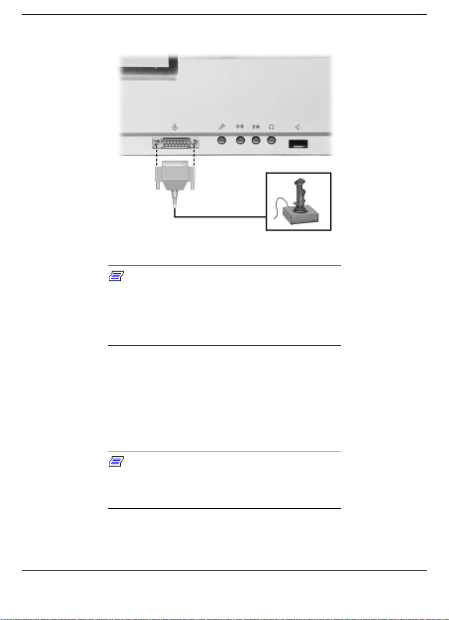
Connecting a MIDI/Game device
External Audio Options
Note:
The NEC Versa Dock automatically
supports sound from the system speakers on the
NEC Versa, and also comes equipped with bui lt-i n
audio ports that let you record and play sound. A
volume control knob lets you control the volume of
connected external speakers or headphones.
Connect audio devices, like a microphone, line-out and line-in devices,
headphones, or optional external speakers to the audio ports as follows.
1.
Power off the NEC Versa Dock and the NEC Versa.
2.
Locate the audio port that you want to use.
Note:
If the audio device you intend to use uses
AC power, the line out port is recommended. If the
audio device is unpowered, the headphone jack is
recommended.
3.
Plug the jack into the port on the side of the NEC Versa Dock.
4-32 Installing Options and Connecting Devices
Page 79
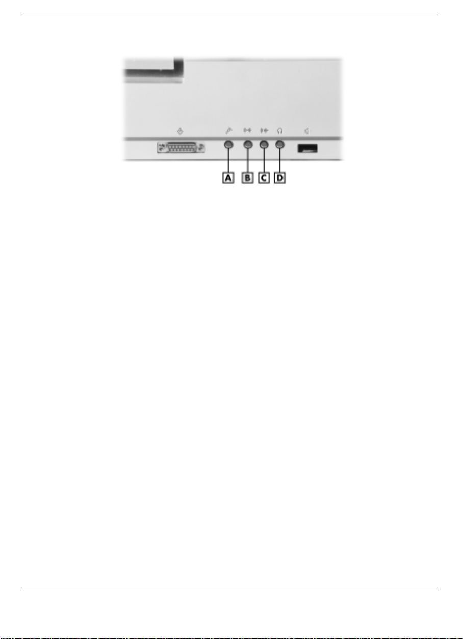
Audio ports
A
- Microphone port B - Line-in port
C
- Line-out/speaker port D - External speaker/headphone port
4.
Power on the NEC Versa Dock and NEC Versa.
Connecting External Speakers
When the NEC Versa is docked, the system defaults to the NEC Versa
speakers. If you want to use optional external speakers with your NEC
Versa Dock, do so as follows.
1.
On Windows 95, click Start, Settings, then Control Panel.
2.
Double click on the Systems icon and click the Device Manager tab.
3.
Double click on the Sound, Video and Game Controllers Icon, then
double click the Maestro Wave/WaveTable Synthesis Devices icon.
4.
Click on the Dock Settings tab.
Installing Options and Connecting Devices 4-33
Page 80
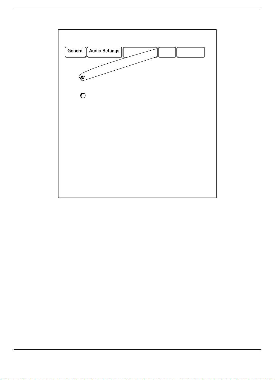
Dock Settings Dialog Box
5.
Change the Output Audio To button from "Notebook Speakers" to
"Docking Station Speakers."
This resets the default speakers to the NEC Versa Dock optional external
speakers. When you undock the system, your NEC Versa speakers will
be functional. When you dock again, the external speakers will be
functional.
The volume control knob on the system controls NEC Versa speaker
volume. The volume control knob on the NEC Versa Dock controls the
volume of external speakers connected to the NEC Versa Dock.
4-34 Installing Options and Connecting Devices
Page 81

Note:
If you are using external speakers or an
external microphone and experienc e so und
distortion or feedback, lower the volume. Having the
microphone and speakers too close to each other
can also cause feedback. Moving the external audio
options away from each other may help.
Installing Options and Connecting Devices 4-35
Page 82

Solving Problems
Problem Checklist
!
Troubleshooting
!
Replacing the Battery
!
If You Need Help
!
5
Page 83

This chapter describes what to do if you encounter problems using the
NEC Versa Dock. Use the information in this chapter to determine what
the problem is and to fix the problem. Often, you can solve problems
that occur by yourself.
If you still need help, see Chapter 6, “Getting Services and Support.”
Problem Checklist
Check the items in the following list if you cannot get the NEC Versa
Dock to work. If these do not help, continue to the “Troubleshooting”
section of this chapter.
Check that the NEC Versa is connected properly to the NEC Versa
!
Dock.
Check that the NEC Versa is not in a power-saving state such as
!
Standby mode.
Verify that the electrical outlet to which the NEC Versa Dock is
!
connected is working. Test the outlet by plugging in a lamp or other
electrical device.
Make sure all cables are connected tightly.
!
Troubleshooting
The power went out and you need to undock the NEC Versa.
!
Undock the NEC Versa. First turn the keylock switch to the
Manual position, remove the CRT table and disconnect any cables
attached to the side of the system. Release the NEC Versa from
the NEC Versa Dock by firmly pulling the front of the NEC Versa
with equal pressure to the right front and the left front. Continue
to pull until the NEC Versa is free from the NEC Versa Dock. In
Chapter 2, see the instructions in the “Emergency Undocking”
section for details.
While trying to record using the microphone, excessive noise is
!
emanating from the speakers.
5-2 Solving Problems
Page 84

Try moving the speakers away from the NEC Versa Dock.
Try adjusting the volume with the volume control knob. If that
doesn’t work, open the Speaker Control Dialog Box in Windows
and adjust the volume control with the slide bar. You can also try
adjusting the Mic control in the Mixer.
When docked, there is no sound from attached external speakers.
!
Check to see that the external speakers are connected properly to
the NEC Versa Dock and are powered on.
Check to see that the Dock Settings tab in the Device Manager is
properly set. See “External Audio Options” in Chapter 4 for
instructions.
When docked, the NEC Versa does not work as it did when docked
!
previously and the settings seem to have changed.
Reboot your system, go into the NEC Versa Setup utility, and
reset the parameters.
The battery in the NEC Versa Dock may need to be replaced. See
“Replacing the Battery” in this chapter for instructions.
The floppy disk drive in the optional VersaBay III Adapter Kit is not
!
detected when the NEC Versa is powered on.
In the BIOS setup, configure and enable diskette B.
Motorized dock or undock is not functioning.
!
Ensure that the keylock is in the full upright position (Normal).
With the key midway between Manual and Normal, motorized
function is disabled.
Drive designations do not appear after starting system using a dual
!
boot configuration.
Reboot the system twice.
Solving Problems 5-3
Page 85

Replacing the Battery
A Lithium Ion (Li-Ion) battery in the NEC Versa Dock maintains the
system configuration for the last system docked. If the NEC Versa Dock
fails to maintain the system configuration information, you may need to
replace the battery.
The battery is located below the left IDE file bay. Replace the battery in
the NEC Versa Dock as follows.
1.
Undock and remove the NEC Versa from the NEC Versa Dock.
2.
Unplug any peripheral devices and cables attached to the NEC Versa
Dock, including the power cable.
3.
Remove the docking tray, front panel,and cable cover. See the
instructions in Chapter 4, “Removing Trays, Panels, and Covers” for
details.
4.
Remove the screw that secures the left IDE bracket and slide the
bracket out of the NEC Versa Dock.
Note:
If you have an IDE device installed in the
file bay, you must disconnect the cables from the
motherboard and remove the device. Refer to
Chapter 4, “Installing Devices in the File Bays” for
instructions.
5.
Locate the battery bay below the left IDE file bay. The battery rests
on the bottom plate of the NEC Versa Dock.
5-4 Solving Problems
Page 86
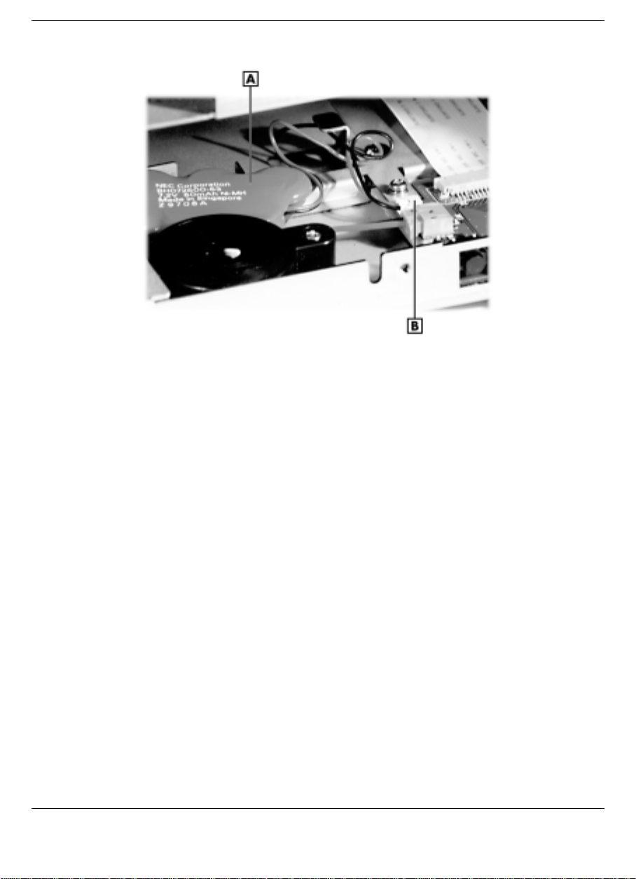
NEC Versa Dock battery
A
- NEC Versa Dock battery B - Battery cable connector
6.
Remove the battery by lifting it out of the NEC Versa Dock.
7.
Gently pull the cable connector on the battery until it is disconnected
from the NEC Versa Dock.
8.
Attach the new battery cable connector to the connector inside the
NEC Versa Dock. Press firmly on the connector until the connection
is secure.
Solving Problems 5-5
Page 87

Be sure to align the cable connectors properly. The
battery could explode if inserted incorrectly.
Replace the battery only with the same or equivalent
type recommended by the manufacturer. Discard
used batteries according to the manufacturer’s
instructions.
9.
Align and reseat the new battery into the battery bay.
10.
Reinstall any IDE devices removed and replace the file bay bracket.
See the instructions in Chapter 4, “Installing Devices in the File
Bays” for details.
11.
Replace the cable cover, docking tray, and front panel of the NEC
Versa Dock. See the instructions in Chapter 4, “Replacing Covers,
Panels, and Trays” for details.
Battery Precautions
To prevent accidental battery ignition, rupture, or explosion, adhere to
the following precautions.
WARNING
5-6 Solving Problems
Page 88

WARNING
There is a danger of explosion if the battery is
incorrectly replaced. Replace only with the same or
equivalent type. Discard used batteries according to
the manufacturer’s instructions. (See the Battery
Disposal page at the end of this guide.)
! Keep the battery away from heat sources
including direct sunlight, open fires, microwave
ovens, and high-voltage containers.
! Do not drop or impact the battery.
! Do not disassemble the battery.
! Do not solder the battery.
! Do not puncture the battery.
! Do not use a battery that appears damaged or
deformed, has any rust on its casing, is
discolored, overheats, or emits a foul odor.
! Keep the battery dry and away from water.
! Keep metal objects away from battery
terminals. Metal objects in contact with the
terminals can cause a short circuit and
damage.
! If the battery leaks onto skin or clothing, wash
! If battery fluid gets in eyes, DO NOT rub; rinse
Battery Disposal
Before disposing of the battery, put adhesive tape on the terminals. The
battery is made of Lithium.
Contact your local waste management officials for information regarding
environmentally sound collection, recycling, and disposal of batteries.
the area immediately. Battery fluid can cause a
skin rash and damage fabric.
with clear water immediately and see a doctor.
Solving Problems 5-7
Page 89

If You Need Help
If you have a problem with your NEC Versa Dock, first review the
checklist and the problems listed previously.
Note:
If you purchased or are using the NEC
Versa Dock or the NEC Versa outside of the United
States or Canada, please contact a local NEC office
or dealer for help available in your area.
If you still need help, see Chapter 6, “Getting Services and Support.”
5-8 Solving Problems
Page 90

6
Getting Services and Support
Quick Reference Chart
!
NECC Web Site
!
NECC FTP Site
!
NECC Support Services
!
Email/Fax To Support Services
!
Page 91

Quick Reference Chart
Service Contact Information
NECC Web and FTP Sites Web address: www.nec-computers.com
FTP site: ftp.neccsdeast.com
NECC Support Services (U.S. and
Canada customers only)
Email to NECC Support Services
through a commercial online
service or the Internet
Note:
the U.S. or Canada, please contact the local NECC
office or their dealers for support and service.
If you purchased your computer outside of
800-632-4525
Fax: 801-981-3133
Internet email address:
[email protected]
If you have access to a telephone, modem, and/or fax machine, you can
use these services to obtain information about your system at any time,
day or night, seven days a week.
Not only do these services provide information about your NEC system,
they can also be used to answer your questions and help solve any
problems you may have with your system, should that ever be necessary.
6-2 Getting Services and Support
Page 92

NECC Web Site
If you have a modem or a network board, you can access the NECC Web
site. You can do this through a commercial online service or through
your Internet account. The NECC Web site contains general information
about NECC and its products, an online store, press releases, reviews,
and service and support information.
Look in the Service and Support area for the following:
technical documentation, including Frequently Asked Questions,
!
reference manuals, and warranty information
BIOS updates, drivers, and Setup Disk files to download
!
contact information, including telephone numbers for Technical
!
Support and links to vendor Web sites
Click, the NECC Customer Service newsletter
!
an automated email form for your technical support questions
!
a Reseller's area (password accessible).
!
To access NECC's Home Page, enter the following Internet Uniform
Resource Locator (URL) in your browser:
http://www.nec-computers.com/
NECC FTP Site
Use the Internet to access the NECC FTP (file transfer protocol) site to
download various files (video drivers, printer drivers, BIOS updates, and
Setup Disk files). The files are essentially the same files as on the NECC
Web site and the NECC Bulletin Board System.
To access the NECC FTP site, enter the following Internet ftp address
through your service:
ftp.neccsdeast.com/
Once in the FTP site, select the pubs directory link and follow the links
to choose and download the file(s) you want.
Getting Services and Support 6-3
Page 93

NECC Support Services
NECC also offers direct technical support through Support Services.
(NECC Support Services is for U.S. and Canadian customers only;
international customers should contact the local NEC office or dealer for
the support and service available in your country.)
Direct assistance is available 24 hours a day, 7 days a week. Call the
NECC Support Services, toll free, at 1-800-632-4525 (U.S. and Canada
only) for the following support.
System hardware — toll-free phone support is limited to the length of
!
the standard warranty.
For hardware support after the standard warranty, you can get system
hardware support for a fee.
Preinstalled software - toll-free phone support for 90 days from the
!
time of your first call to the NECC Support Services.
After the initial 90 days, you can get preinstalled software support for
a fee.
Please have available your system's name, model number, serial number,
and as much information as possible about your system's problem before
calling.
For outside the U.S. or Canada, please contact your local NEC office or
dealer for the support and service available in your country.
E-mail/Fax Support Services
The NECC Support Services offers technical support by e-mail over the
Internet network if you have a modem. The Internet address is:
You can also fax technical questions to the NECC Support Services if
you have access to a fax machine or fax/modem. The fax number is:
801-981-3133
6-4 Getting Services and Support
Page 94

When using the email or fax support service, you should include the
following words in the subject field for prompt response from the
appropriate technical person:
Desktop
!
Monitor
!
Notebook.
!
You should provide as much specific information about your questions
as possible. Also, if you are sending a fax, please include your voice
telephone number and your fax number with the question. You will
receive a response to your questions within one business day.
Getting Services and Support 6-5
Page 95

Specifications
Features
!
Input/Output Facilities
!
Expansion Capabilities
!
Indicator LEDs
!
Power Supply
!
Power Cables
!
Connector: IEC 320
!
Dimensions
!
A
Environmental Requirements
!
Page 96

Features
The following specifications are standard except where noted.
Two PCI card slots for one full-size card and one half-size card or
!
two half-size cards.
Optional 10/100 Versa Dock PCI Ethernet Card that provides a
!
networking solution for the NEC Versa Dock.
Two file bays that support the installation of a 5.25-inch or 3.5 inch
!
(with a 3.5-inch Universal Installation Kit) IDE drive such as an
optional SuperDisk drive, CD-ROM reader, tape drive, or hard disk
drive. One bay also supports the installation of an optional VersaBay
III Adapter Kit to support VersaBay III devices.
Monitor stand that allows access to external PCI card connectors and
!
NEC Versa PC card slots.
Port replication of most NEC Versa I/O ports.
!
Input/Output Facilities
Docking connector — 240-pin connector
!
Keyboard — PS/2-style, 6-pin connector
!
Mouse — PS/2-style, 6-pin connector
!
Two Universal Serial Bus (USB) — 4-pin connector
!
Parallel port —25-pin D-sub connector
!
External monitor port —15-pin D-sub connector
!
Serial port —9-pin D-sub connector
!
MIDI/Game port — 15-pin D-sub connector
!
Microphone — 3.5-mm jack; accepts monaural mini-microphone jack
!
Headphone/Speaker jack — 3.5-mm jack; accepts stereo mini-
!
headphones or speaker jack
Line-In jack — 3.5-mm jack; accepts stereo mini-line-in jack
!
A-2 Specifications
Page 97

Line-Out/Speaker jack — 3.5-mm jack; accepts stereo mini-line-out
!
jack
Expansion Capabilities
Drive Bays — Two half-height 5.25-inch drive bays that support IDE
!
devices; one of the bays also supports the installation of an optional
VersaBay III Adapter Kit to convert the bay into a VersaBay III slot.
Expansion Slots — Two PCI card slots; one that supports a full-size
!
or half-size card; one that supports a half-size card only.
Indicator LEDs
Docking/Undocking LED
!
Key Lock Status LED
!
IDE Drive Access LED
!
Diskette Drive Access LED
!
Battery Charge LED
!
Power Supply
Input
!
Range: 90–135/180–265 VAC, switch select
Frequency: 50/60 Hz
Input current: 6.5A @ 115 VAC; 3.5A @230 VAC
Output
!
Maximum power: 200 watt (W)
Hold-up time: 7 ms at full load @ 115 VAC
Over-current protection: +5V <50A; +/-12V < 25A
Specifications A-3
Page 98

Over-voltage protection:
+5V – trip point <7.0V, recycle AC to reset
+3.3V – trip point <+4.6V, recycle AC to reset
+12V – trip point <+16.0V, recycle AC to reset
Power Cables
North America
!
Rating: 120 V, 7 A
Plug: NEMA 5-15P
Cable: SVT or SJT 18/3 AWG; less than 15 ft (4.5 m) in length
Connector: IEC320
Europe
!
Rating: 230 V (220-240 V), 10 A
Plug: Country specific
Cable: H05VV-F or H05VVH2-F; less than 15 ft (4.5 m) in length
Connector: EN60320
Dimensions
Height: 5.2 in. (132 mm )
!
Width: 14.98 in. (380.6 mm)
!
Depth: 16.93 in. (430 mm)Weight: 25 lb
!
Environmental Requirements
Operating Environment
!
A-4 Specifications
Page 99

Temperature: 41(F to 95(F (5(C to 35(C)
Humidity: 20% to 80% (non-condensing)
Storage Environment
!
Temperature: –4(F to 140(F (–20(C to 60(C)
Humidity: 5% to 95% (non-condensing)
Specifications A-5
Page 100

Index
A
Audio options, 4-32
B
Battery
disposal, 5-7
precautions, 5-6
replacement, 5-4
Battery charge status
LED, 1-7
C
Cable specifications, 1-3
Carton contents, 1-2
Cold docking, 2-6
Connecting external devices, 4-2
audio options, 4-32
external monitor, 4-27
keyboard and mouse, 4-26
MIDI/Game devices, 4-31
parallel devices, 4-29
printers, 4-29
serial devices, 4-24
speakers, 4-33
USB devices, 4-30
Connecting IDE device cables, 4-8
Connecting the power cable, 2-2
Connecting VersaBay III adapter kit
cables, 4-10
D
Device Manager
checking PCI card configuration, 4-24
Docking, 2-6
cold, 2-6
hot, 2-7
warm, 2-6
Docking station
front, 1-4
top, 1-4
Docking Station
features, 1-3
Docking status
LED, 1-6
Dual Booting, 2-11
Dual-boot systems
booting issues, 4-10
E
Emergency undocking, 2-17
Environmental requirem ents, 1- 11
External devices
connecting, 4-2
External monitor, 4-27
External speakers, 4-33
F
Features, 1-3
File bay installation, 4-11
FTP site, 6-3
G
Game port, 4-31
H
Hardware setup, 2-2
Height adjustment lever, 1-8
Hot docking, 2-7
I
IDE device cables, 4-8
IDE Drive Access
LED, 1-6
IDE hard drive
installing, 4-10
Introduction, 1-2
K
Kensington Lock, 1-11
Index-1
 Loading...