

Page 1

PROPRIETARY NOTICE AND LIABILITY DISCLAIMER
The information disclosed in this document, including all designs and related materials, is the
valuable property of NEC Corporation (NEC) and/or its licensors. NEC and/or its licensors,
as appropriate, reserve all patent, copyright and other proprietary rights to this document,
including all design, manufacturing,reproduction, use, and sales rights thereto, except to the
extent said rights are expressly granted to others.
The NEC product(s) discussed in this document are warranted in accordance with the terms
of the Warranty Statement accompanying each product. However, actual performance of
each such product is dependent upon factors such as system configuration, customer data,
and operator control. Since implementation by customers of each product may vary, the
suitability of specific product configurations and applications must be determined by the
customer and is not warranted by NEC.
To allow for design and specification improvements, the information in this document is
subject to change at any time, without notice. Reproduction of this document or portions
thereof without prior written approval of NEC is prohibited.
MultiSync and Versa are U.S. registered trademarks of NEC Technologies, Inc.
Docking Station 6000 is a U.S. trademark of NEC Technologies, Inc.
All other product, brand, or trade names used in this publication are the trademarks or registered trademarks of their respective
trademark owners.
First Printing — July 1996
Copyright 1996 Copyright 1996
NEC Technologies, Inc. NEC Corporation
1414 Massachusetts Avenue 7-1 Shiba 5-Chome, Minato-Ku
Boxborough, MA 01719 Tokyo 108-01, Japan
All Rights Reserved All Rights Reserved
Page 2

Using this Guide
The NEC Versa® Series Docking Station™ 6000 User’s Guide gives you
the information you need to maximize the use of your docking station. Read
this guide to become familiar with the Docking Station 6000 and its features. For specific information, see the following chapters.
n Chapter 1 introduces you to Docking Station 6000 capabilities and
features. This chapter also describes the correct operating and storage
environment for the docking station and how to care for the unit.
n Chapter 2 provides instructions for docking and undocking an NEC
Versa on the docking station.
n Chapter 3 explains setting up the software to use your docking station
and NEC Versa together.
n Chapter 4 details how to add options to the docking station. These
options include expansion boards and various types of drives.
n Chapter 5 directs you through connecting peripheral devices, like an
external keyboard, mouse, monitor, printer, and audio options.
n Appendix A provides docking station specifications.
n Appendix B provides connector pinouts.
n Appendix C gives a quick reference to common problems and solutions.
Appendix C also provides NEC technical support numbers.
This document, along with your NEC Versa user’s guide and Windows
documentation, provides all the information you need to effectively use the
Docking Station 6000.
Using this Guide vii
Page 3
TEXT SETUP
To make this guide as easy to use as possible, text is set up in the following
ways.
n Warnings, cautions, and notes are set up in following format.
WARNING
Warnings alert you to situations that can cause personal injury or
harm.
CAUTION
Cautions indicate situations that can damage system hardware or
software.
Notes give particularly important information about the topic
being discussed.
n Names of keys are printed as they appear on the keyboard, for example,
Ctrl, Alt, or Enter.
n Text that you must type or keys that you must press are presented in bold
type. For example, type dir and press Enter.
RELATED DOCUMENTS
See the following documents for information related to the NEC Versa Series Docking Station 6000 and NEC Versa operation:
n Your NEC Versa user’s guide.
n The Microsoft Windows and MS-DOS Operating System documentation
that came with your NEC Versa.
n Manuals and setup instructions for any devices that you are installing in
or connecting to the docking station.
viii Using this Guide
Page 4

Contents
Using this Guide .................................................................................................... vii
Text Setup.......................................................................................... viii
Related Documents............................................................................. viii
1 Introducing the NEC Docking Station 6000
What’s in the Box............................................................................... 1-1
NEC Docking Station 6000 Features................................................... 1-2
Front and Left Side Features.......................................................... 1-3
LEDs and the Volume Control Knob ......................................... 1-6
Back Features................................................................................ 1-7
Internal Features............................................................................ 1-9
The Right Environment ....................................................................... 1-11
Operating Environment.................................................................. 1-11
Storage Environment ..................................................................... 1-11
Docking Station 6000 Care................................................................. 1-11
Precautions.................................................................................... 1-11
Routine Care................................................................................. 1-12
Battery Charging................................................................................ 1-13
2 Docking/Undocking the NEC Versa
Hardware Setup.................................................................................. 2-1
Connecting the Power Cable .......................................................... 2-1
Preparing the NEC Versa for Docking ........................................... 2-4
Docking the NEC Versa...................................................................... 2-6
Undocking the NEC Versa.................................................................. 2-10
Normal Undocking ........................................................................ 2-10
Emergency Undocking................................................................... 2-12
3 Setting Up and Using the Software
Plug and Play Systems........................................................................ 3-1
Non-Plug and Play Systems................................................................ 3-2
Running the Setup Utility............................................................... 3-2
Windows for Workgroups Setup............................................... 3-3
Windows 95 Setup.................................................................... 3-4
Contents iii
Page 5

Docking Station 6000 Setup Software ............................................ 3-5
Option Configuration ..................................................................... 3-5
Drivers.......................................................................................... 3-6
Quick Start......................................................................................... 3-7
4 Adding Options
Cover Removal................................................................................... 4-2
Cover Replacement............................................................................. 4-4
Expansion Boards............................................................................... 4-6
Precautions.................................................................................... 4-7
Slot Locations ............................................................................... 4-7
Installation .................................................................................... 4-8
Removal........................................................................................ 4-11
Data Storage Devices ......................................................................... 4-12
Preparing the Drive........................................................................ 4-13
Installing Drives in the Front Bay................................................... 4-13
Hard Disk Drives........................................................................... 4-32
VersaBay II Adapter Installation ......................................................... 4-45
Removing the Drive Cage.............................................................. 4-45
Securing the NEC VersaBay II Adapter......................................... 4-46
Attaching Cables........................................................................... 4-48
Finishing Up.................................................................................. 4-55
Choosing a Configuration......................................................... 3-5
Removing the Drive Cage......................................................... 4-13
Attaching the Drive to the Drive Cage....................................... 4-15
Attaching the Cables................................................................. 4-17
Finishing Up............................................................................. 4-30
Preparing the Hard Disk Drive .................................................. 4-33
Specifying Master and Slave Drives .......................................... 4-33
Installing the Drive................................................................... 4-34
Attaching IDE Drive Cables ..................................................... 4-36
Attaching SCSI Drive Cables.................................................... 4-41
5 Connecting Peripheral Devices
External Monitor................................................................................ 5-2
External Keyboard.............................................................................. 5-5
External Mouse.................................................................................. 5-6
External Audio Options ...................................................................... 5-6
Microphone................................................................................... 5-7
iv Contents
Page 6

Headphones or Speakers................................................................ 5-8
Line In/Line Out............................................................................ 5-8
Telephone Cable............................................................................ 5-9
Gaming Devices ............................................................................ 5-10
Parallel Devices ............................................................................. 5-10
Serial Devices................................................................................ 5-12
External SCSI Devices .................................................................. 5-13
A Specifications
B Pin Assignments
Keyboard and Mouse Ports................................................................. B-1
COM Port.......................................................................................... B-2
Printer Port......................................................................................... B-3
Monitor Port....................................................................................... B-4
AT Interface Connectors ..................................................................... B-5
Expansion Port................................................................................... B-8
Headphones.............................................................................. 5-8
Speakers................................................................................... 5-8
Line In ..................................................................................... 5-9
Line Out ................................................................................... 5-9
C Solving Problems
Problem Checklist............................................................................... C-1
Troubleshooting.................................................................................. C-1
If You Need Help ............................................................................... C-2
Contents v
Page 7

vi Contents
Page 8

Introducing the
1
WHAT’S IN THE BOX
NEC Docking Station 6000
The NEC Versa® Series Docking Station™ 6000 transforms your NEC
Versa 6000 Series notebook computer into a full-featured desktop dynamo.
A built-in sound system and three option bays let you create a powerful
workstation or a robust multimedia presentation system.
Once you fill in the hardware, the NEC Docking Station 6000 gives you
unparalleled software compatibility. Using the latest technology, the docking
station supports the newest Plug and Play boards as well as older non-Plug
and Play legacy boards.
The sleek ergonomic docking station design makes it pleasant to look at and
easy to use. Its innovative docking mechanism insures secure and easy
docking and undocking.
This chapter describes the features and capabilities of the docking station.
Carefully unpack the shipping carton and check its contents. Accessories are
in the box tucked into the side of the shipping carton.
Make sure you have the hardware components shown in the following figure
and that they are in good condition. If anything is damaged or missing,
contact your dealer immediately.
Introducing the NEC Docking Station 6000 1-1
Page 9
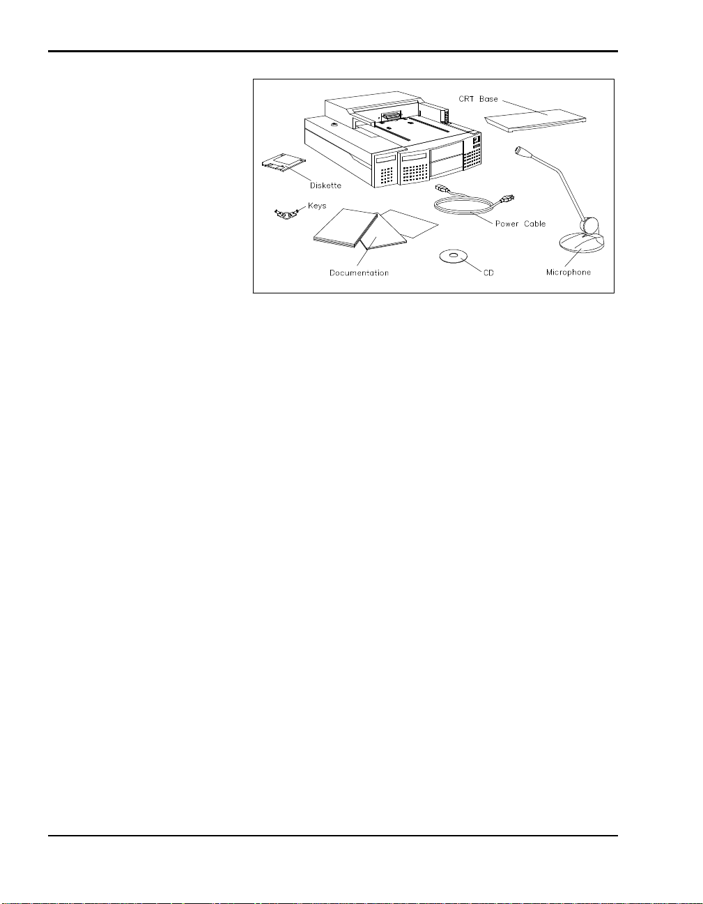
*Not shown is a bag containing optional drive signal cables, a power
cable, and an audio cable.
NEC DOCKING STATION 6000 FEATURES
The docking station has the following features, which are described in
greater detail in the sections that follow.
n Support for full Windows 95 configuration and Plug and Play options.
What’s in the box?
n Support for Windows for Workgroups and MS-DOS 6.22.
n Support and on-board connectors for both SCSI and IDE interfaces.
n An electronic docking mechanism that makes docking and undocking
easier than ever.
n A CRT base that lets you put an external monitor on top of the docking
station to save premium desktop real estate.
1-2 Introducing the NEC Docking Station 6000
Page 10
CAUTION
Always use the CRT base if you are going to put an external CRT
monitor on the docking station. Never place an external monitor or
any other heavy object directly on the docking station or NEC Versa
without the CRT base. Doing so can damage the unit.
The CRT base weight limit is 60 lb (27.2 kg), equivalent to a 17-inch
NEC monitor. Do not exceed the weight limit. Doing so can damage
the unit.
n A 3-position lock to ensure that your NEC Versa is not undocked or your
docking station used without authorization.
n Stereo speakers for outstanding quality sound.
n Ports on the back of the unit for connecting external peripherals like a
PS/2-style keyboard, PS/2-style mouse, printer, monitor, and much more.
n LEDs on the front of the docking station to track docking station and
NEC Versa status.
n Three drive bays and three full-size expansion board slots for expanding
docking station capabilities.
Front and Left Side Features
The following features are found on the front and left side of the Docking
Station 6000. Features are described after the figure.
Introducing the NEC Docking Station 6000 1-3
Page 11
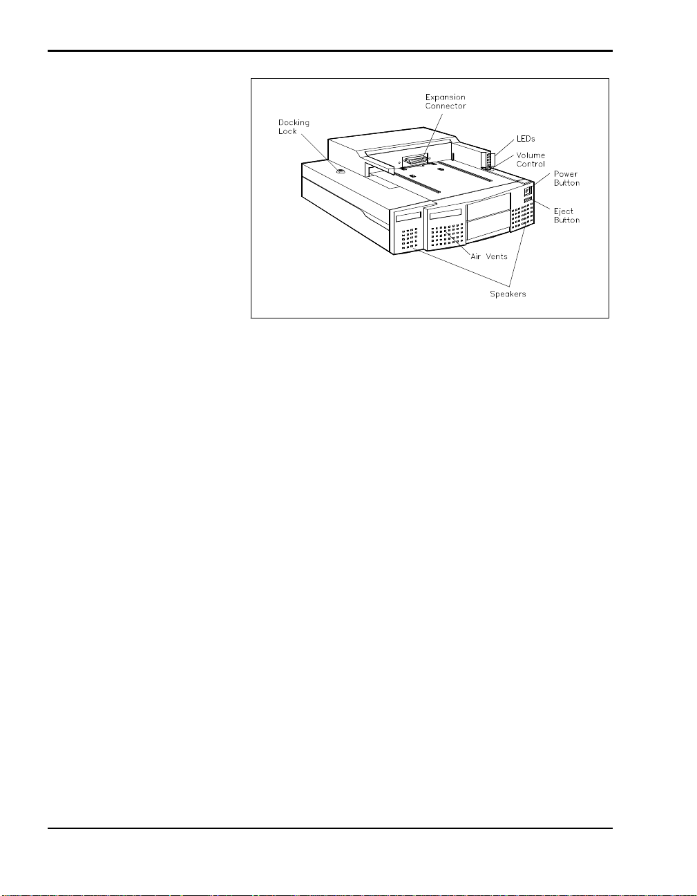
Front and side features
n Electronic Docking Mechanism – This innovative docking mechanism
makes docking and undocking easier than ever.
After setting up the hardware, all you do is position the NEC Versa on
the docking station and give it a firm push towards the connector. The
mechanism reaches out, grasps the NEC Versa, and completes the docking process.
n Expansion Connector — This connector attaches the NEC Versa and the
docking station interface board.
n Air Vents – These allow air circulation to keep the docking station and
its components from over heating.
n LEDs – Five LEDs on the front of the docking station let you monitor
docking status, hard disk drive access, diskette drive access, NEC Versa
battery, and Keylock status. (LED functions and lighting sequences are
described in the next section under “LEDs.”)
n Volume Control Knob – This conveniently located knob lets you control
the volume of sound output through docking station speakers.
n Power Button – The power button on the front panel of the docking
station turns on and off power to the docked NEC Versa. For Plug and
Play systems using Windows 95, this button acts as a Resume switch if
the NEC Versa is in Suspend mode.
1-4 Introducing the NEC Docking Station 6000
Page 12

n Eject Button – Pressing the eject button undocks the NEC Versa. All you
have to do is remove the laptop.
n Stereo Speakers – These speakers provide excellent sound quality. Use
your applications software or the volume control know to control speaker
volume and balance.
n External Bay Access – These front panels are removable to allow access
to drives installed in the bays.
n The Docking Lock – This lock provides three settings that let you control
NEC Versa removal.
Manual – lets you remove the NEC Versa manually. Use the unlocked position for emergency undocking only. Otherwise, use the Normal lock setting for normal use and the Locked setting to secure your
system to the docking station.
Normal – this default position allows you to dock or undock the
NEC Versa through software (for Windows 95 Plug and Play systems)
or the Eject button. Set the key lock to this position for normal use. To
prevent electrical damage, manual undocking is not allowed when the
lock is in this state.
Locked – secures your NEC Versa to the docking station. This setting keeps the NEC Versa from being removed from the docking station.
You must use the key to unlock the unit before removing the NEC Versa.
If no computer is docked and the key is in the Locked position, no one
else can use their computer on the docking station.
n Security Alarm – The locking mechanism comes equipped with an audi-
ble security alarm that sounds if someone tries to undock the NEC Versa
while the key is in the locked position.
Introducing the NEC Docking Station 6000 1-5
Page 13
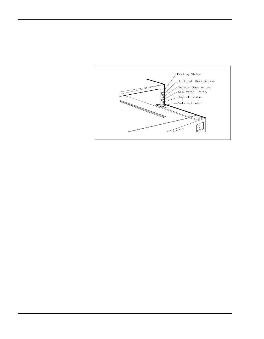
LEDs and the Volume Control Knob
NEC Docking Station 6000 LEDs and the volume control knob are located
on the front of the docking station. LED functions and lighting sequences are
described after the figure.
n Docking Status – lights green and yellow
Steady Green – When the Main Power Switch is turned on, no NEC
Versa is docked, and the lock is in the Normal position, the docking
status LED lights steady green indicating that it is ready for docking.
Status LEDs and the Volume Control Knob
Blinking Green – If docking or undocking is unsuccessful due to an
error or jam, the LED blinks.
Steady Yellow – Once the NEC Versa docking process completes
successfully, the LED lights a steady yellow.
n Hard Disk Drive Access – lights green when a hard disk drive in either
the NEC Versa or the docking station is being accessed.
n Diskette Drive Access – lights green when a diskette in the NEC Versa is
accessed.
n NEC Versa Battery – lights green
Steady green – when the notebook battery is charging.
Blinks green – if an abnormal charge condition occurs.
Off – indicates that the battery is fully charged.
1-6 Introducing the NEC Docking Station 6000
Page 14
n Keylock Status
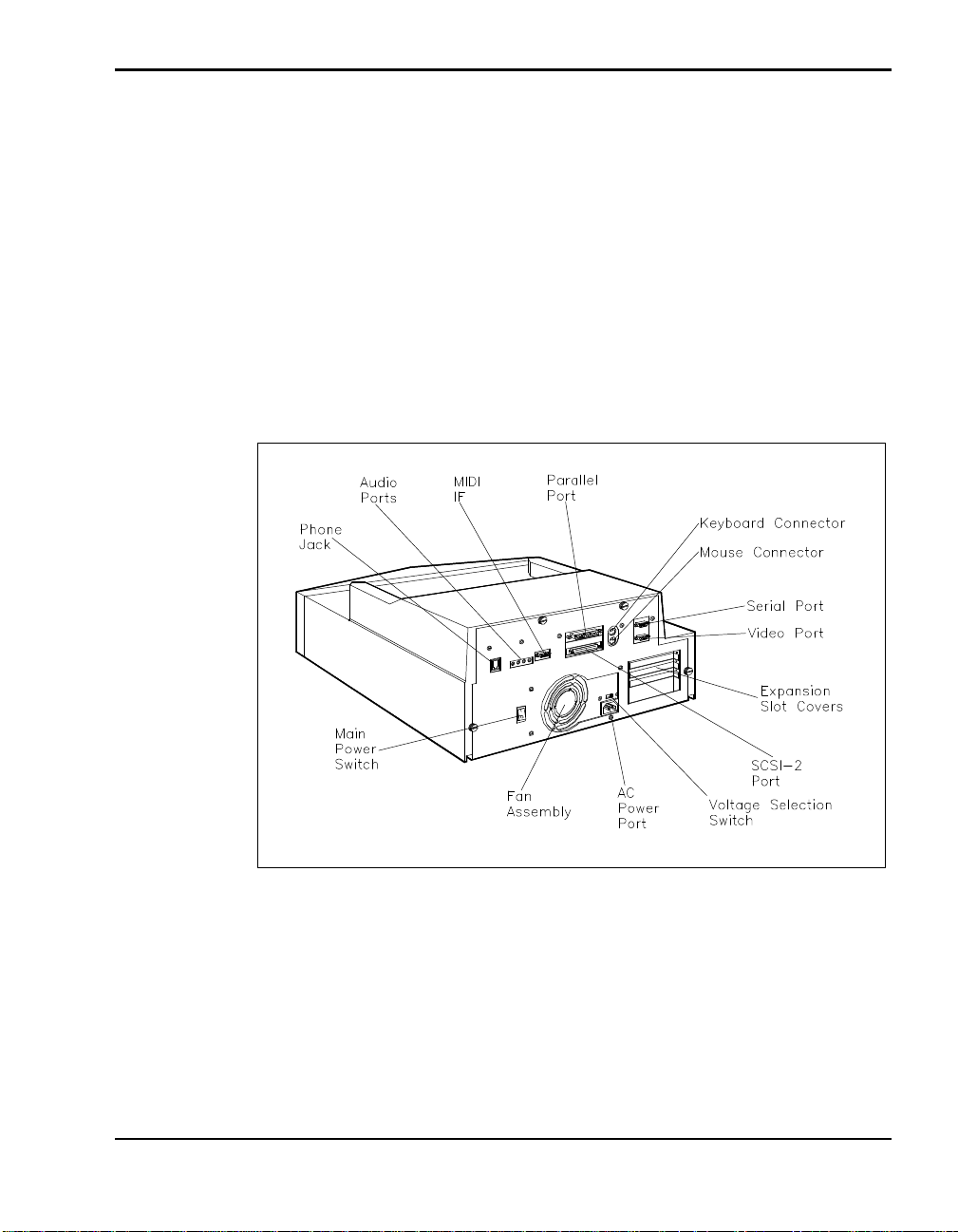
Back Features
Features on the back of the docking station are shown in the following
figure. Descriptions follow the figure.
Off — indicates that the lock is set to Normal.
Steady Green — indicates that the lock is set to Manual or Locked.
Blinks Green — indicates that the keylock is set to Manual or
Locked and a software eject command was issued or the Eject button
was pressed.
Features on the back of the docking station
n Thumbscrews – secure the cover to the docking station. When un-
screwed, allow cover removal.
n Keyboard Connector – allows the connection of an external PS/2-style
keyboard.
Introducing the NEC Docking Station 6000 1-7
Page 15

n Mouse Connector – allows the connection of an external PS/2-style
mouse.
n MIDI Game Port – lets you connect gaming devices such as joy stick.
n Video Port – lets you attach an external monitor to the docking station.
n RJ11 Telephone Jack – lets you plug in a standard phone cable to use the
internal NEC Versa modem.
n Serial Port (COM port) – lets you connect a serial device, such as a
printer or modem, to the docking station.
n Expansion Slot Covers – protect the expansion board slots when no
boards are installed. If you add expansion boards to the docking station,
these covers are removed.
n Power Port – lets you connect the power cord to the docking station and
AC power.
n Voltage Selection Switch – lets you select the correct voltage to use in
your area.
n Docking Station Power Switch – lets you turn on power to the docking
station.
n Fan Assembly – Provides proper cooling for the power supply that regu-
lates power in the docking station.
n SCSI-II Port – lets you connect an external SCSI-2 device, like an exter-
nal CD-ROM, scanner, or hard disk drive, to the docking station.
n Parallel Port – lets you connect a parallel device, like an external printer,
to the docking station.
n Audio Ports:
Microphone (MIC) – lets you plug in an external microphone for
monaural recording.
Headphones – lets you plug in stereo headphones or external
speakers.
Line In – lets you use another audio system, like a CD player, as a
stereo input source. Use a cable to connect to the Line Out port on
the other audio system to record or play.
1-8 Introducing the NEC Docking Station 6000
Page 16
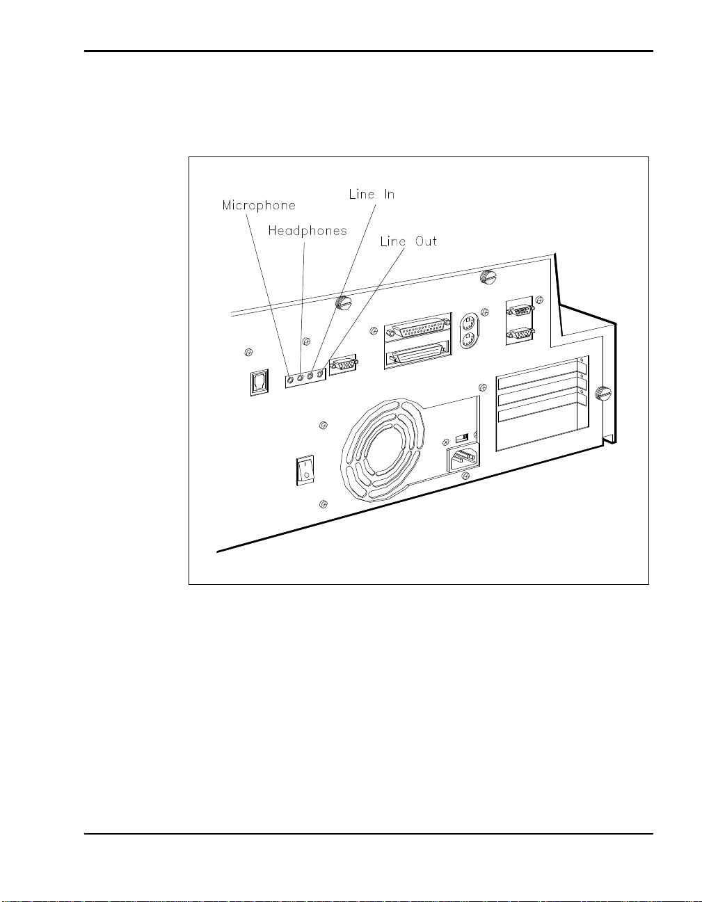
Line Out – lets the docking station act as a stereo input source for
another audio system. Connect this port to a Line In port on another
audio system to play or record.
Audio ports
Internal Features
Internal NEC Docking Station 6000 features are shown next. The following
figure shows the docking station with its cover removed. Descriptions of internal features follow the figure.
Introducing the NEC Docking Station 6000 1-9
Page 17
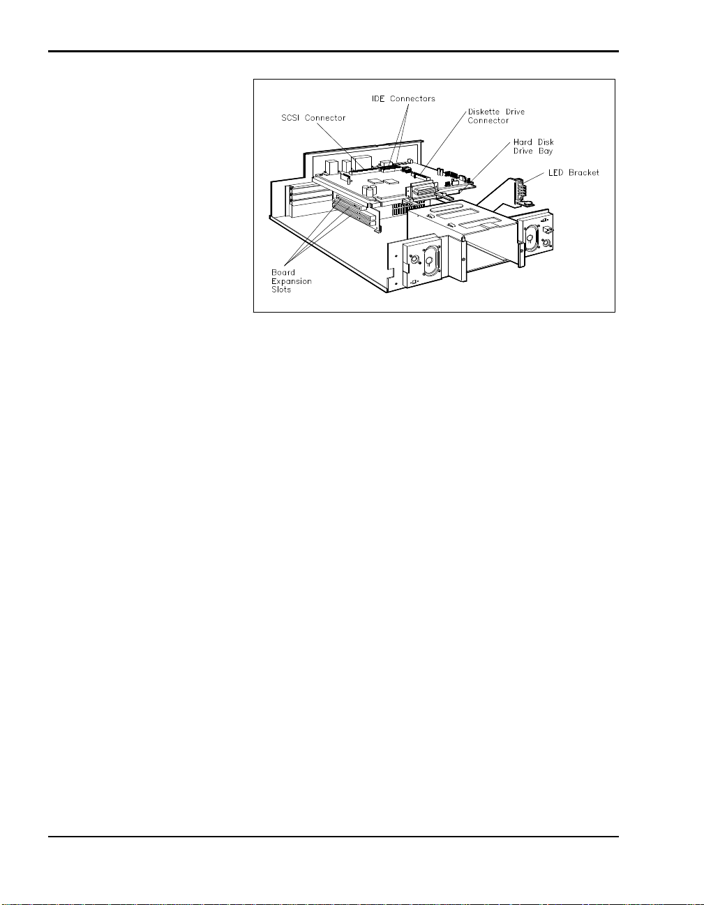
Internal features
n Board Expansion Slots – three full-size expansion slots
one full-size PCI card slot
one full-size ISA card slot
one full-size PCI/ISA card slot
n External Access Bay – allows the installation of up to two 5 1/4-inch
half-height drives.
n Hard Disk Drive Bay – lets you install one 3 1/2-inch internal hard disk
drive.
n I/O Connectors – One each of the following:
Diskette Drive Connector
IDE Disk Connector
SCSI Disk Connector.
n LED Bracket – supports docking station status LEDs and volume control
knob.
n Speakers – provide exceptional sound for the integrated docking station
sound system.
1-10 Introducing the NEC Docking Station 6000
Page 18

THE RIGHT ENVIRONMENT
Before setting up the docking station, find a good location for using it. Here
are some guidelines.
n Select a flat, sturdy surface, like a desktop or table, so you have access
to both the front and back of the unit.
n Choose an area away from extremely warm or cold surroundings, direct
sunlight, excessive dust, vibration, shock or moisture.
Operating Environment
Use the docking station in a location that meets the following environmental
conditions:
n Temperature: 41°F to 95°F (5°C to 35°C)
n Humidity: 20% to 80% (noncondensing)
Storage Environment
Store the docking station in a location that meets the following conditions:
n Temperature: –4°F to 122°F (–20°C to 50°C)
n Humidity: 15% to 85% (noncondensing)
DOCKING STATION 6000 CARE
With protective measures and proper care, you can keep your docking station in top operating condition. Follow the measures given next to maintain
your docking station.
Precautions
Follow these precautions when using and storing the NEC Docking
Station 6000.
n Do not use or store the docking station in direct sunlight or near radiant
heat sources for an excessive length of time. Heat from these sources can
raise the internal temperature of the unit and damage its parts.
n Do not use or store the docking station in dusty environments.
n Do not use or store the docking station near chemicals.
Introducing the NEC Docking Station 6000 1-11
Page 19
Routine Care
n Do not cover the air vents or put anything near enough to them to block
air circulation.
n Avoid excessive vibration or shock. Dropping the docking station or
knocking it over can cause serious damage.
n Keep the docking station away from machinery that generates strong
electric or magnetic fields.
n Do not place heavy objects on the docking station. Make sure the CRT
base is in position before placing an external monitor on it. The base is
designed to support an external monitor. Do not place other heavy objects on the CRT base.
Maintain the condition of your docking station by periodically following the
general procedures listed next.
WARNING
For safety, power off and unplug the docking station and NEC Versa
before cleaning.
n Clean the outside of the docking station with a soft clean cloth.
n Remove stubborn stains with a cloth slightly dampened with a mild de-
tergent. Never use a strong solution or spray cleaner on any part of the
unit.
n Check the docking station regularly for loose material, such a paper,
books, magazines, that might block the air vents and prevent proper air
circulation.
n Keep food and liquids away from the docking station and NEC Versa.
1-12 Introducing the NEC Docking Station 6000
Page 20

BATTERY CHARGING
The docking station charges the battery installed in your NEC Versa as long
as the computer is docked, the docking station is plugged into AC power,
and main docking station power switch is on.
Battery charging occurs whether or not you are using your system.
Introducing the NEC Docking Station 6000 1-13
Page 21
Docking/Undocking
2
HARDWARE SETUP
the NEC Versa
Getting your NEC Docking Station 6000 up and running is easy. This
chapter provides the procedures you need to get started. They include:
n Connecting the power cable to AC power and the docking station and
powering on the docking station.
n Preparing the NEC Versa 6000 and connecting it to the docking station.
n Powering on the NEC Versa.
The first time you use the NEC Docking Station 6000, you
must set system parameters on the NEC Versa hard disk. You must
set docking station parameters on every hard disk drive that you
plan to use with the docking station. These procedures are described in Chapter 3.
This chapter also describes how to undock the NEC Versa from the docking
station when you want to use the notebook by itself.
Connecting the Power Cable
Follow the instructions given next in the order presented to get your NEC
Versa and docking station up and running.
Connect the AC power cable to the docking station and AC
power before docking the computer.
Docking/Undocking the NEC Versa 2-1
Page 22
The power cable that came with the docking station provides power to the
docking station and the NEC Versa. Connect the docking station power
cable as follows.
1. Position the docking station on a flat surface close to an AC outlet.
2. Verify that the voltage selection switch is set correctly for your country.
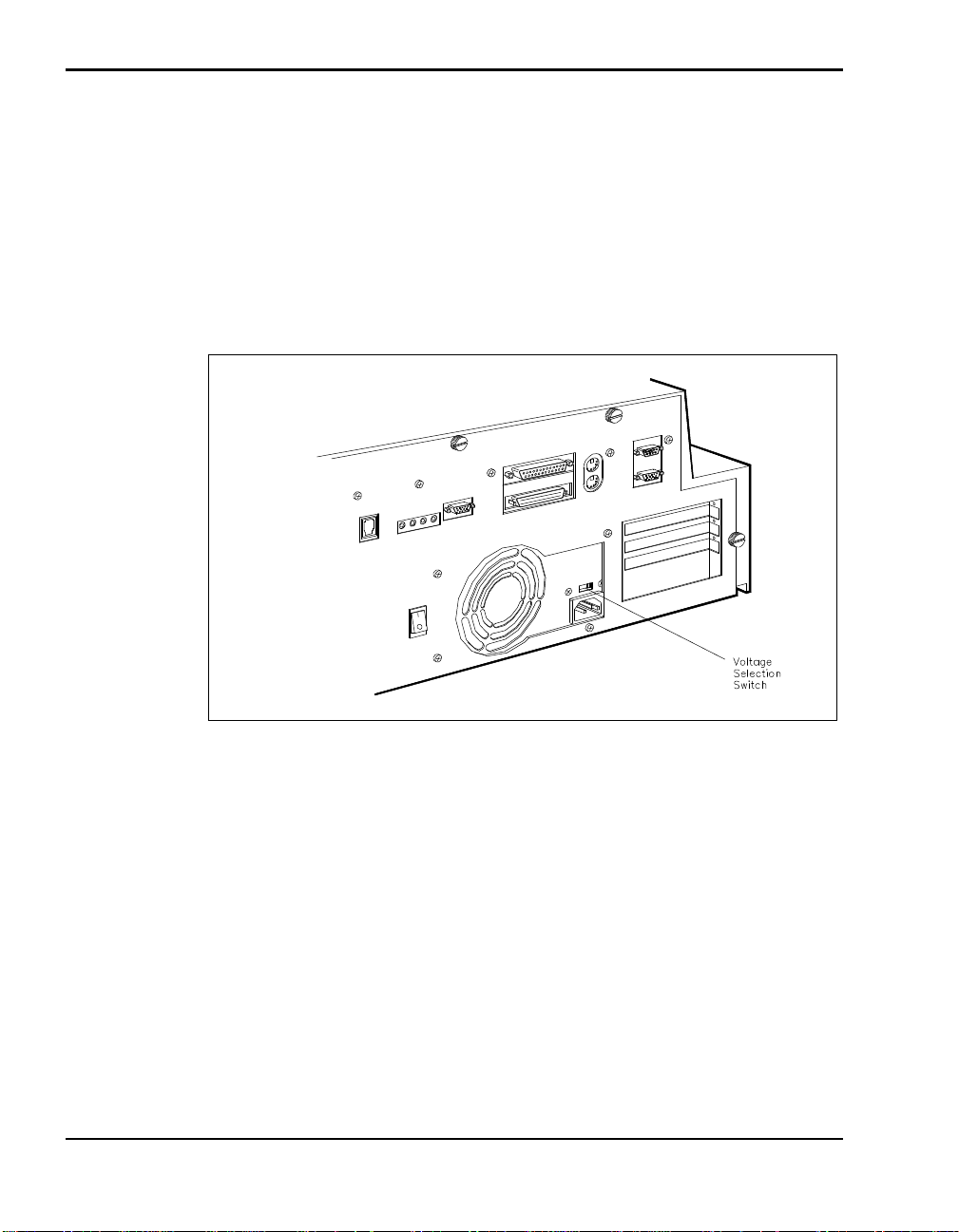
Insert a pointed object, like the tip of a ball-point pen, to move the switch
to the correct setting. (The switch is set at the factory for 115 voltage.)
Locating the voltage selection switch
3. Attach one end of the cable to the AC power port on the docking station.
4. Attach the other end to a properly grounded wall outlet.
2-2 Docking/Undocking the NEC Versa
Page 23
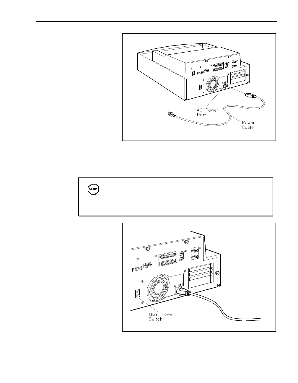
Connecting the power cable
5. Locate the main power switch on the back of the docking station. Press
ON to turn on docking station power.
Docking station power must be turned on for the electronic
docking mechanism to work. Pressing the main power button on the
back of the unit provides the necessary power.
Powering on the docking station
Docking/Undocking the NEC Versa 2-3
Page 24
CAUTION
Disconnecting the power cable, turning off power, or experiencing a
power outage while running the docking station and NEC Versa can
result in a system crash. If this occurs, see the instructions in
“Emergency Undocking” later in this chapter.
Once you connect the power cable to the docking station, keep it plugged in
and the power turned on. That way, the docking station is always ready for
the docking procedure.
Preparing the NEC Versa for Docking
Follow the procedure given next to prepare the NEC Versa for docking.
1. Set NEC Versa power for your system as follows.
n If you have a Plug and Play NEC Versa, you can either put your sys-
tem into Suspend mode or leave power on for docking.
For example, the NEC Versa 6000 with Windows 95 running is a
Plug and Play system.
n If you have a non-Plug and Play system, turn off system power before
docking. Systems running Windows for Workgroups do not support
plug and play.
Make sure your system is in Suspend mode or powered off as
appropriate before docking. If the NEC Versa is in Active mode or
power is on during docking, the docking station ejects the computer.
2. If you are running the NEC Versa on AC power, disconnect the AC
adapter cable from the NEC Versa.
Before disconnecting power, save any open files or close
open applications to avoid data loss.
2-4 Docking/Undocking the NEC Versa
Page 25
3. Verify that the power cord is plugged into the docking station and that
docking station power is turned on. (See “Connecting the Power Cable”
for details.)
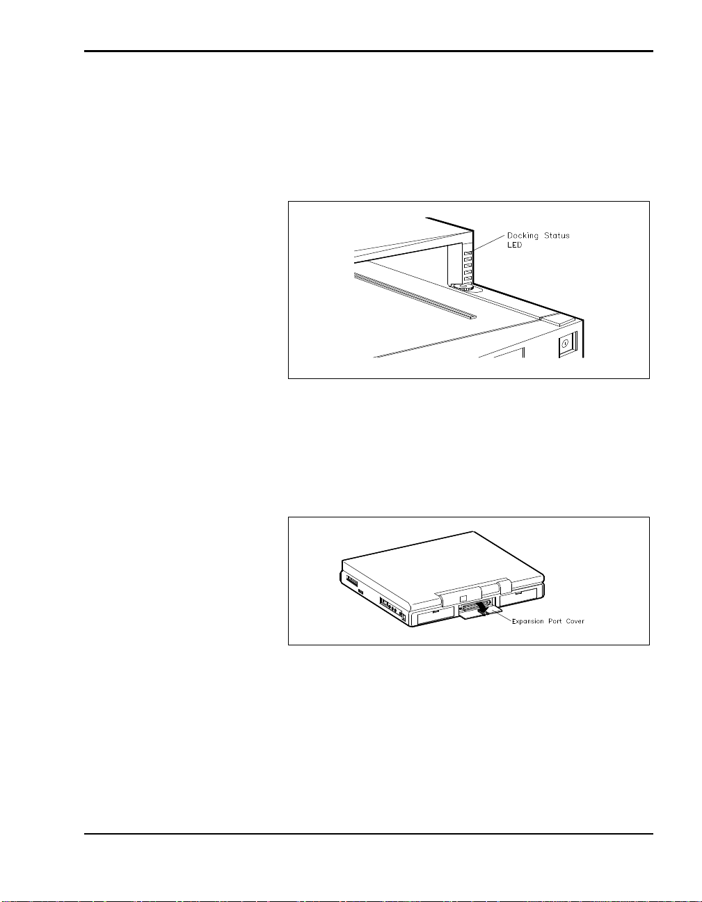
The Docking LED should be a steady green, which indicates that it is
ready for docking.
Docking LED
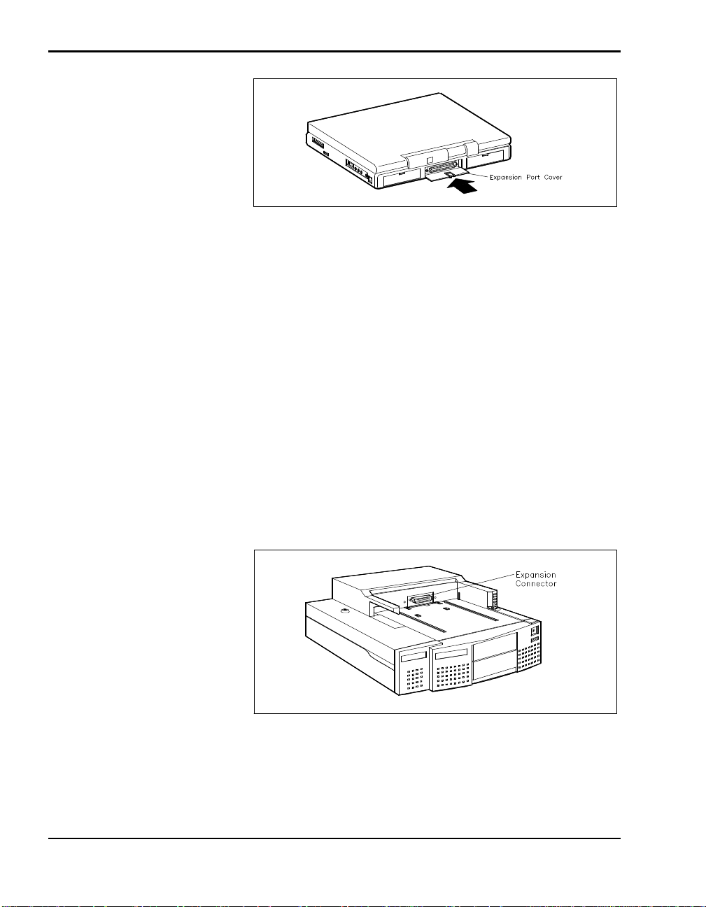
4. On the back of the NEC Versa, open the expansion port cover and slide it
underneath the expansion port.
Check that all other NEC Versa port covers are closed.
Opening the NEC Versa expansion port cover
Docking/Undocking the NEC Versa 2-5
Page 26
DOCKING THE NEC VERSA
You can dock the NEC Versa in one of two modes:
n Cold Docking – with NEC Versa system power off. This method works
for all NEC Versa models that support docking.
n Warm Docking – with NEC Versa power on and the system in Suspend
mode. This procedure can be used with NEC Versa 6000 systems with
the Windows 95 operating system.
n Hot Docking – with NEC Versa power on. This procedure can be used
with NEC Versa 6000 systems with the Windows 95 operating system.
Stowing the expansion port cover
Use the following steps to dock your NEC Versa.
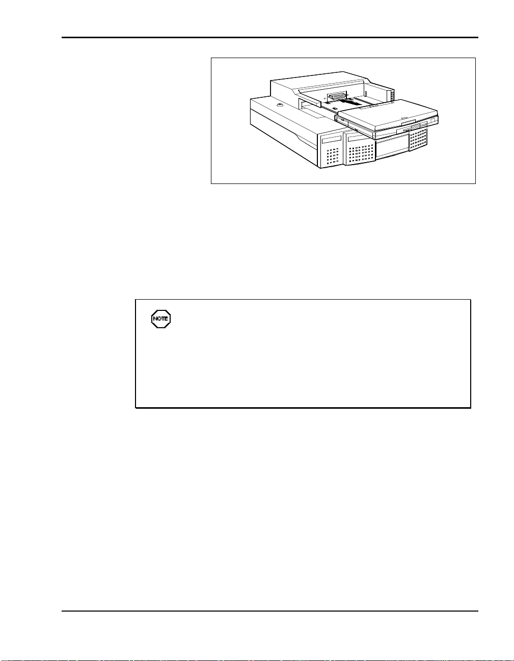
1. Locate the expansion connector on the docking station.
2. Set the NEC Versa on the docking station and align the expansion port
and connector.
2-6 Docking/Undocking the NEC Versa
Locating the expansion connector
Page 27
Docking the NEC Versa
3. Push against the front of the NEC Versa to put it in position to dock.
Keep the notebook computer aligned evenly with the connector. Firmly
push against the center of the computer or push with equal pressure
against the left front and right front of the NEC Versa.
Keep the NEC Versa straight. If the computer is pushed at an
angle, it does not dock properly.
To prevent connector damage, the docking mechanism will not start
to dock if the expansion connectors are not aligned properly. If this
occurs, adjust the NEC Versa position by lifting the front of the computer or shifting it left or right.
The sensor inside the docking connector detects the NEC Versa and
initiates the mechanical docking sequence. The mechanism pulls the NEC
Versa in and docks it. Some noise during docking is normal. When
docking is successful, the Docking LED lights a steady yellow.
Docking/Undocking the NEC Versa 2-7
Page 28
If the Docking LED blinks, push a little harder on the NEC
Versa to reseat it for docking. This usually corrects the problem and
the LED turns to a steady yellow.
If the LED continues to blink, call your authorized NEC service
representative. A blinking Docking LED indicates that something
went wrong with the docking sequence due to an error or hardware
failure.
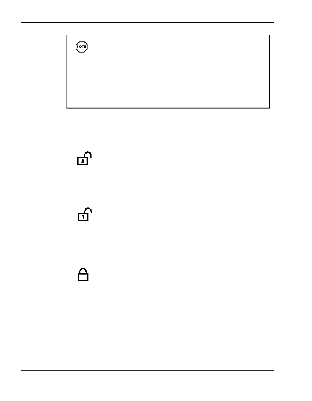
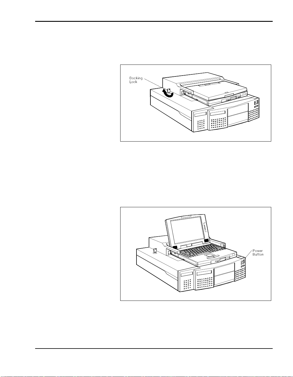
4. To lock your NEC Versa onto the docking station, insert the key into the
lock and turn it. The Docking Lock provides three lock settings that let
you control NEC Versa removal.
Manual – lets you dock and undock the NEC Versa manually. Use
the Manual position for emergency undocking only. Otherwise, use the
Normal lock setting for normal use and the Locked setting to secure your
system to the docking station.
The keylock LED lights a steady green when set to Manual.
Normal – allows you to dock or undock the NEC Versa through
software (for Windows 95 Plug and Play systems) or the Eject button.
Set the key lock to this position for normal use. To prevent electrical
damage, manual undocking is allowed. (This is the default lock setting.)
The keylock LED is off when set to Normal.
Locked – secures your NEC Versa to the docking station. This set-
ting keeps the NEC Versa from being removed from the docking station.
You must use the key to unlock the unit before removing the NEC Versa.
If no computer is docked and the key is in the Locked position, no one
else can use their computer on the docking station. Even if someone
manually docks an NEC Versa, they will be unable to use the docking
station and its features.
The Keylock LED lights a steady green when set to Locked.
2-8 Docking/Undocking the NEC Versa
Page 29
The locking mechanism comes equipped with an audible security alarm
that sounds if someone tries to undock the NEC Versa while the key is in
the locked position.
Locking the NEC Versa
5. If using the NEC Versa without an external monitor, open the LCD
panel.
6. To turn on NEC Versa power, locate the power button on the front of the
docking station, push it in momentarily and release it.
Powering on
Docking/Undocking the NEC Versa 2-9
Page 30

After docking the NEC Versa for the first time, you do not always need to
use the power button to power on your system. If the docking station remains plugged in and the main power switch on the back of the unit stays
turned on, the NEC Versa automatically powers on after docking. If you
turn off AC power through the main power switch or by unplugging the
docking station, you must use the power button the first time you dock your
NEC Versa.
UNDOCKING THE NEC VERSA
NEC recommends that you power down your NEC Versa before undocking.
n For standard undocking procedures, follow the instructions in “Normal
Undocking.”
n If power to the docking station is interrupted unexpectedly, follow the in-
structions in “Emergency Undocking.” You may need this procedure in
case of a power failure or motor jam.
Normal Undocking
Undock your NEC Versa as follows.
1. Check the status of your NEC Versa power:
n If you are running Windows 95, you can either put your system into
Suspend mode or leave the system operating to undock.
n If you are running Windows for Workgroups, save your files, and
power off your NEC Versa. (To power off the NEC Versa, press the
power button on the front panel of the docking station.)
2. For easier undocking, close the LCD panel.(This is not required, but is
recommended.) If using software undocking, do not close the panel.
2-10 Docking/Undocking the NEC Versa
Page 31
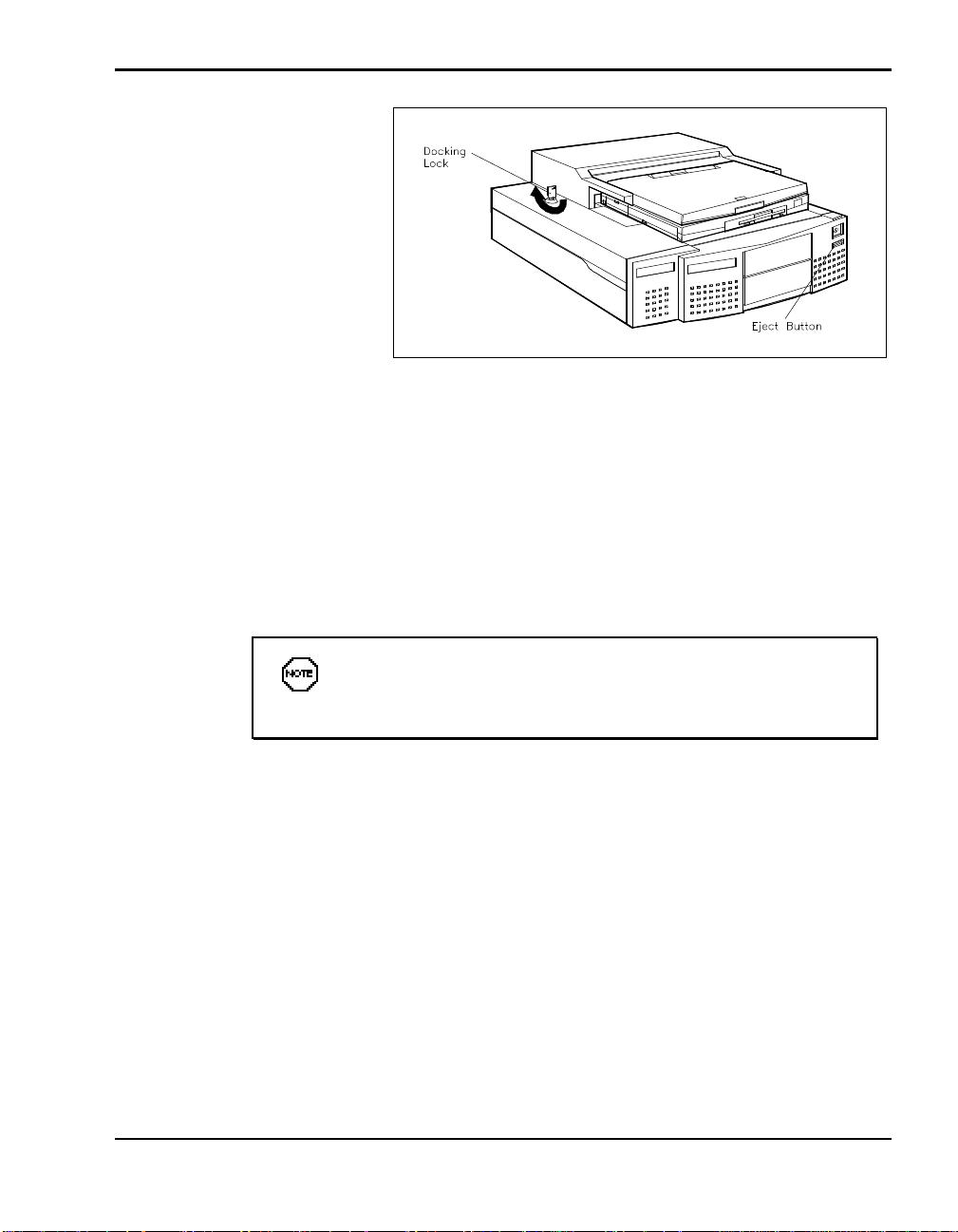
Eject button and lock location
3. Check the status of the lock. You cannot undock the NEC Versa if the
lock is in the Locked or Manual position.
4. Press the Eject button on the front panel of the docking station.
To use Windows 95 software to undock the NEC Versa, locate the Eject
icon on the screen and click. The software puts your NEC Versa into
Suspend mode and initiates the undocking sequence.
If the NEC Versa does not eject properly using the front panel
Eject button, go to the next section “Emergency Undocking.”
5. Once the connection is broken, pull the NEC Versa forward and remove
it from the docking station.
Docking/Undocking the NEC Versa 2-11
Page 32
Emergency Undocking
You may need to undock your NEC Versa when power to the docking
station is unavailable or is unexpectedly interrupted.
When necessary, use the following emergency undocking procedure to
undock the NEC Versa:
1. If possible, turn off NEC Versa power or put the system into Suspend
mode (a half moon is displayed on the LCD panel).
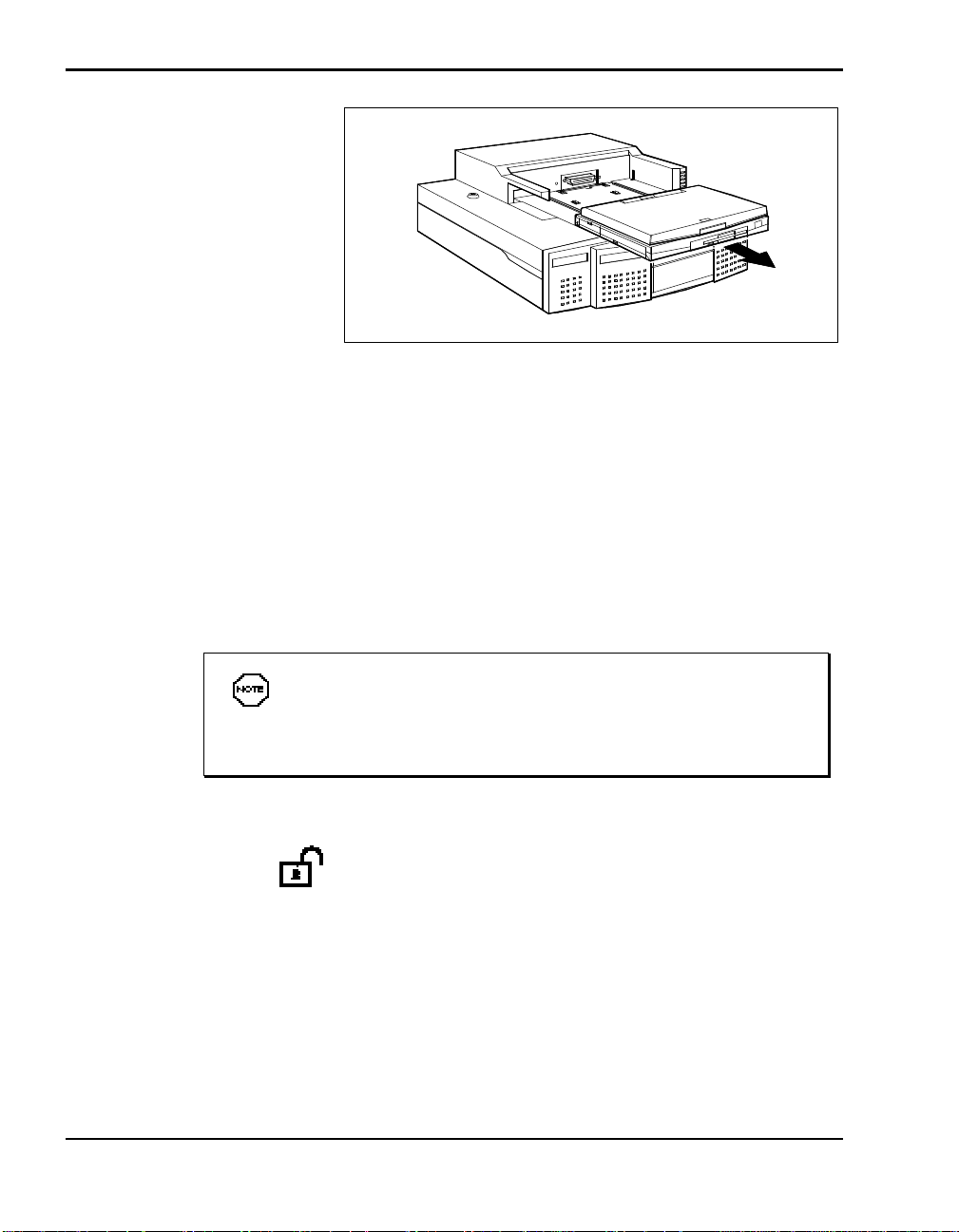
Removing the NEC Versa
If the NEC Versa cannot be powered off or put into Suspend
mode, turn off the main power switch on the back of the docking
station before continuing.
2. Turn the docking station key to the Manual position:
3. Close the NEC Versa LCD panel.
4. Pull the NEC Versa forward and lift it out of the docking station.
2-12 Docking/Undocking the NEC Versa
Page 33
CAUTION
Make sure the key is in the Manual position before MANUALLY
removing the NEC Versa. To prevent mechanical damage, do not
try to remove the NEC Versa manually with the key in any other
position.
5. Always turn the key back to the Normal position.
Docking/Undocking the NEC Versa 2-13
Page 34

Setting Up and
3
Using the Software
Your Docking Station 6000 comes with all the software you need to get it up
and running. The docking station setup utility installs the following onto
your NEC Versa 6000 hard disk drive:
n Online Docking Station User’s Guide (called the Docking Station Guide)
n Intel Plug and Play Kit (Windows for Workgroups systems only)
n EZ-SCSI drivers
n Docking Station drivers and message handler.
To set up your docking station, go to one of the following sections in this
chapter:
n Go to “Running the Setup Utility.”
n If you are extremely familiar with software setup programs and the NEC
Versa family of computers, the “Quick Start” section at the end of this
chapter may be all you need.
PLUG AND PLAY SYSTEMS
Plug and Play systems, like the NEC Versa 6000 with the Windows 95
operating system and Plug and Play BIOS, require no special software
installation. To install the online version of the docking station user’s guide
on your NEC Versa, simply follow the instructions in “Running the Setup
Utility.”
The NEC Versa 6000 with Windows 95 as its operating system supports
Plug and Play options in the docking station. Simply install the option, dock
the NEC Versa 6000, and reboot the system. The option is automatically
configured. (Some options may require that you install specific option drivers. Check the guide that came with the option to determine if this is true of
the option you plan to install.)
Setting Up and Using the Software 3-1
Page 35
Your NEC Versa, the option, and the operating system in use must all support Plug and Play for automatic configuration. If you install a non-Plug and
Play option, you must configure it according to its conventions.
NON-PLUG AND PLAY SYSTEMS
NEC Versa models running Windows for Workgroups do not support Plug
and Play options because of software restrictions. To use options in a
docking station with non-Plug and Play systems or options, you must
configure the option according to the NEC Versa and option requirements.
(See your NEC Versa user’s guide and the option guide.)
Setting up the software to use your NEC Docking Station 6000 is easy to
do. The setup utility loads the docking station SCSI drivers and installs the
online user’s guide on your NEC Versa hard drive.
RUNNING THE SETUP UTILITY
The first time you use the Docking Station 6000, you must set up the software in the NEC Versa to recognize the Docking Station 6000 and make full
use of its features.
Setting up the software as described here creates a configuration called
“Docking Station 6000” that your NEC Versa can use when it is connected
to the Docking Station 6000. When the NEC Versa is not docked, you can
specify the original NEC Versa configuration, called “Mobile.”
You must perform software setup on each hard disk that you
plan to use with the Docking Station 6000.
Run the Docking Station 6000 Software Setup utility as follows.
1. Make sure the CD-ROM reader is installed in the NEC Versa.
2. Follow the instructions in Chapter 2 and dock your NEC Versa on the
Docking Station 6000 and power on. (This step is optional, however,
docking your system first is recommended.)
In Windows for Workgroups systems, boot into Windows, if Windows is
not already opened. (Type win and press Enter to open Windows.)
3-2 Setting Up and Using the Software
Page 36
3. Close any Windows applications that may be running (for example, the
NEC Battery Gauge or Virus Scan software).
4. Insert the Docking Station 6000 Software Setup CD into the reader.
5. Proceed to the section that is appropriate for your system as follows:
n Go to the next section, “Windows for Workgroups Setup” if you are
running Windows for Workgroups.
n Go to the section “Windows 95 Setup” if you are running
Windows 95.
Windows for Workgroups Setup
In Windows for Workgroups, complete setup as follows.
1. Select “Run” from the File pull-down menu in Program Manager.
2. Enter the CD drive letter, a colon, backslash and setup. Press “OK” or
Enter to start Setup. For example, enter one of the following:
d:\setup or e:\setup
A Welcome screen appears.
3. Respond to the utility prompts as follows:
Press the “Next” button to accept the default loading directories. To
change a directory, press “Browse” and specify the new location.
The utility displays a progress gauge showing you that the required data
is being installed.
4. After the Plug and Play Kit is installed, press “No” at the prompt to re-
boot your computer.
CAUTION
After the Plug and Play Kit is installed, make sure you select “No” at
the prompt to reboot the computer. Pressing Yes stops the setup
process before it is complete.
Setting Up and Using the Software 3-3
Page 37

5. Follow the on-screen prompts to install EZ-SCSI. To accept the defaults,
press “Next” at each screen.
n To register your EZ-SCSI software, fill in the blanks on the registra-
In the Host Adapter field, choose Adapter type AIC-7870 from the
n Once EZ-SCSI is installed, reboot your system as prompted to finish
See the section, “Docking Station 6000 Setup Software,” for information
about using Docking Station 6000 software.
Windows 95 Setup
In Windows 95, the NEC Docking Station Software Setup utility starts
automatically.
1. Select “Run” from the Start menu.
2. Enter the CD drive letter, a colon, backslash and setup. Press “OK” or
Enter to start Setup. For example, enter one of the following:
tion screen.
drop-down list.
the docking station setup process.
d:\setup or e:\setup
A Welcome screen appears.
3. Respond to the utility prompts to load docking station software and EZ-
SCSI drivers.
n Press the “Next” button to accept the default loading directories. To
change a directory, press “Browse” and specify the new location.
The utility displays a progress gauge showing you that the required
data is being installed.
n To register your EZ-SCSI software, fill in the blanks on the registra-
tion screen.
In the Adapter Type field, choose Adapter type AIC-7870 from the
drop-down list.
4. Once EZ-SCSI is installed, reboot your system as prompted to finish the
docking station setup process.
3-4 Setting Up and Using the Software
Page 38

See the next section, “Docking Station 6000 Setup Software,” for information about using Docking Station 6000 software.
Docking Station 6000 Setup Software
This section describes how to use the software that the Docking Station 6000 Setup utility loads in your NEC Versa. At start up, the NEC
Versa lets you choose a configuration to use. See “Choosing a Configuration” for information.
Choosing a Configuration
After setting up the Docking Station 6000 software, your NEC Versa bootup differs from its original procedure. The new boot up sequence lets you
choose which configuration to use.
Use the new boot up procedure as follows:
1. Power on your NEC Versa as you would normally. A menu similar to the
following is displayed.
1. Mobile Configuration
2. Docking Station Configuration
2. Enter the appropriate number for the configuration you want to use as
follows:
n Mobile Configuration — Select this configuration to use the NEC
Versa by itself.
n Docking Station Configuration — Use this configuration when you
dock your NEC Versa on the Docking Station 6000.
Option Configuration
Follow the instructions that come with your option to configure devices installed in the Docking Station 6000.
If your NEC Versa BIOS, its operating system, and the option are all Plug
and Play-compliant, you should be able to install the option, reboot your
system, and use the option. Check the documentation that came with the
optional device to determine whether or not the option requires special
drivers. If it does, load the drivers according to the instructions that come
with the option.
Setting Up and Using the Software 3-5
Page 39

Drivers
Configure non-Plug and Play options according to the instructions that came
with the options and those in the NEC Versa user’s guide. If you install nonPlug and Play devices in a Plug and Play system, you must still configure
the option according to its requirements.
For some options, like a second IDE drive or diskette drive installed in the
docking station, you must run the Setup utility to set the correct parameters.
Some systems automatically detect the new device and its parameters. Check
that the settings reflect the options installed in the docking station.
Windows 95 supports multiple configurations for your NEC Versa. Versions of MS-DOS above revision 6.0 also support multiple configurations.
After running the NEC Docking Station 6000 Setup utility, simply reboot
your system when docked or undocked and select the configuration to use
from the start-up menu.
Use the NEC Versa 6000 Setup utility to enable and disable SCSI drivers.
Access Setup when you boot the system and the prompt “Press <F2> for
BIOS SETUP” appears on your screen.
3-6 Setting Up and Using the Software
Page 40
QUICK START
If you are familiar with setup programs and the NEC Versa family of computers, follow these steps to run the Docking Station 6000 Setup utility.
1. Install the CD-ROM reader in the NEC Versa 6000.
2. Dock your NEC Versa on the Docking Station 6000 and power on the
3. Boot into Windows.
4. Close any Windows applications that may be running.
5. Insert the Docking Station 6000 Software Setup CD into the reader. For
system. (This is optional, however, we do recommend that you dock your
system. See Chapter 2 for docking instructions.)
Windows for Workgroups systems, go to step 6 and continue.
In Windows 95 systems, select “Run” from the Start menu. Type
d:\setup (where d is the CD drive letter) and press Enter or click “OK.”
Respond to the utility as prompted.
If you register your EZ-SCSI software, choose Host Adapter AIC-7870.
When Setup is complete, reboot your system at the prompt.
6. From the Windows Program Manager, access the File pull-down menu
and select “Run.” Type d:\setup (where d is the CD drive letter) and
press Enter or click “OK.”
7. Respond to the utility as prompted.
After the Plug and Play Kit is installed, press “No” at the prompt to reboot your computer.
CAUTION
After the Plug and Play Kit is installed, make sure you select “No” at
the prompt to reboot the computer. Pressing Yes stops the setup
process before it is complete.
If you register your EZ-SCSI software, choose Adapter type AIC-7870.
8. When Setup is complete, reboot your system when prompted.
Setting Up and Using the Software 3-7
Page 41

4
Adding Options
You can install the following options in the NEC Versa Docking
Station 6000.
n In the front device storage bay, up to two 5 1/4-inch, half-height drives
or an optional VersaBay II adapter. The front bay allows external access
to the drives.
n In the internal device storage bay, one 3 1/2-inch internal hard disk drive.
n In the expansion board bay, a total of three boards:
One PCI card slot for a full-size or half-size PCI board
One ISA card slot for a full-size or half-size ISA board
One combination PCI/ISA card slot for a full- or half-size PCI or
ISA board.
Installing these options require that you remove the docking station cover.
Once the options are installed, you must replace the cover before using the
docking station.
This chapter provides the information you need to remove and replace the
docking station cover, install expansion boards, and add optional drives and
the VersaBay II adapter.
Before installing an option or expansion board in the docking station, read
the documentation that came with the option or board. Set any switches
required on the board or option before beginning the installation procedure.
Adding Options 4-1
Page 42
COVER REMOVAL
Follow these steps to remove the docking station cover.
Make sure docking station power is off, the NEC Versa is not
docked, peripheral devices are disconnected, and cables are detached from the docking station before beginning installation procedures.
1. Turn the Docking Lock to the Manual position for easier cover removal
and replacement
2. Remove the CRT Base from the docking station.
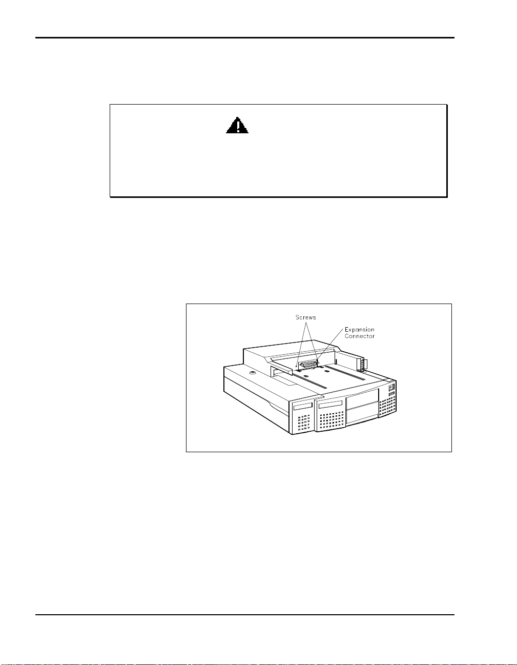
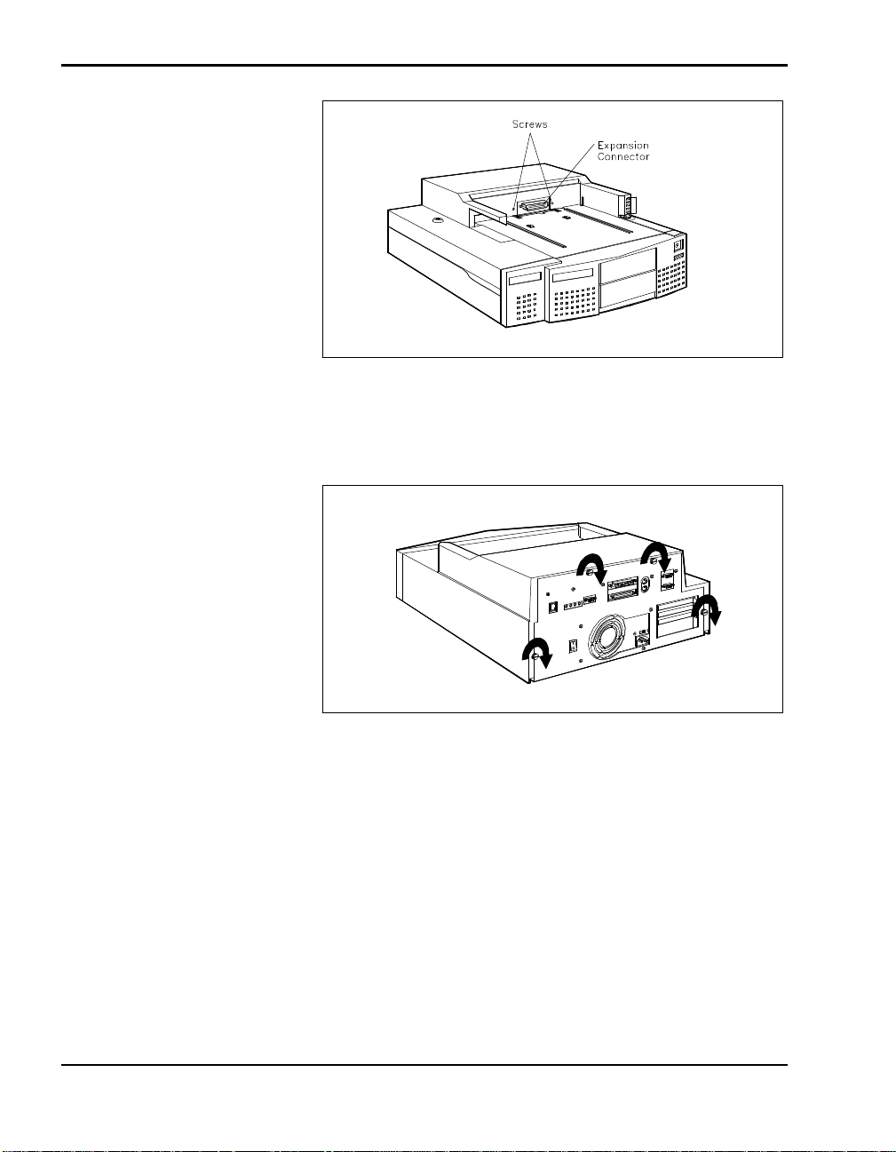
3. Locate and remove the two screws next to the expansion connector.
WARNING
Locating two screws
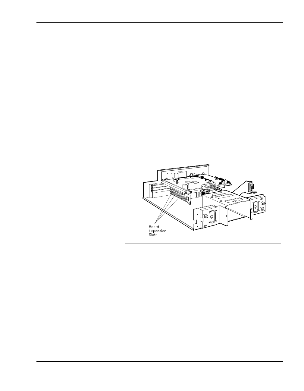
4. Locate and unscrew the thumbscrews on the back of the docking station.
4-2 Adding Options
Page 43
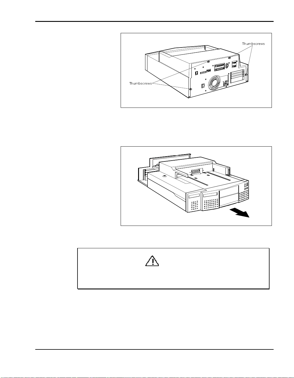
Thumbscrew locations
5. Pull the cover forward to clear the expansion connector.
Clearing the expansion connector
CAUTION
When disassembling the docking station, be careful not to drop
anything into it. Doing so can damage the unit.
Adding Options 4-3
Page 44
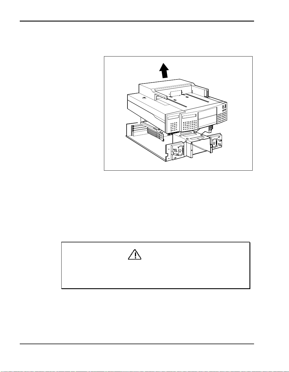
6. Pull the sides of the cover outward slightly and lift the cover up and off
of the docking station.
Removing the cover
COVER REPLACEMENT
Once your options are installed, replace the docking station cover as follows:
1. Align and lower the cover over the front of the docking station. Make
sure the cover clears the expansion connector.
Be careful not to catch any wires or cables when replacing the
cover. Move cables aside if they look like they may be pinched or
squeezed when you replace the cover.
4-4 Adding Options
CAUTION
Page 45
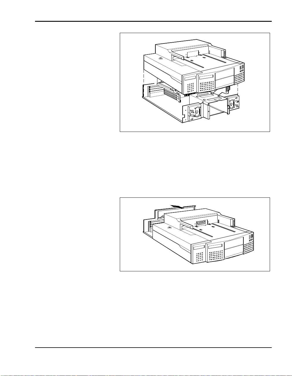
Positioning the cover
2. Pull the sides of the cover outward slightly.
3. Push the cover towards the back of the docking station. Make sure the
expansion connector and the volume control knob protrude through the
openings in the cover.
Replacing the cover
4. Slide the cover all the way onto the docking station.
5. Replace the two screw on the front of the docking station.
Adding Options 4-5
Page 46
Replacing the two screws
6. Replace the thumbscrews on the back of the docking station to secure the
cover.
Securing the cover
7. Replace the two screws next to the docking connector.
EXPANSION BOARDS
You can install three full-size or half-size PCI-bus or AT-style expansion
boards in the NEC Docking Station 6000. Before beginning the installation,
check the documentation that came with the board. If you have any switches
to set on the board, do so before starting this procedure.
4-6 Adding Options
Page 47
Precautions
Always remove expansion boards from the shipping material very carefully.
Static discharge can damage board components. Take the following
precautions when handling boards:
n Avoid carpets in cool, dry areas.
n Before handling a board, discharge any static electricity by touching a
n Always hold a board by its edges. Avoid touching the components on the
Slot Locations
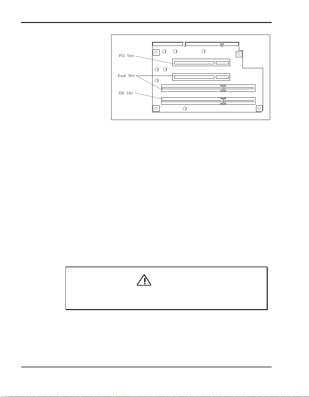
Slot locations for expansion boards are shown in the following figure.
grounded metal object.
board.
Expansion slot locations
These slots accommodate the following expansion board types:
n One slot accepts any industry-standard PCI-bus board.
n One slot accepts any industry standard 8- or 16-bit ISA expansion board.
n One slot accepts either a PCI-bus or ISA expansion board.
Adding Options 4-7
Page 48
Installation
PCI and ISA slot locations
Follow these steps to install an expansion board in the docking station.
1. Prepare for board installation as follows:
n Disconnect and remove the NEC Versa from the docking station.
n Turn off and unplug the docking station.
4-8 Adding Options
n Disconnect any peripheral devices connected to the docking station.
n Remove the docking station cover. See “Cover Removal” earlier in
this section for information on removing the cover.
n Position the docking station so you have access to the side where the
expansion slots are located.
CAUTION
Be careful not to drop anything into the docking station. Doing so
can damage the unit.
Page 49
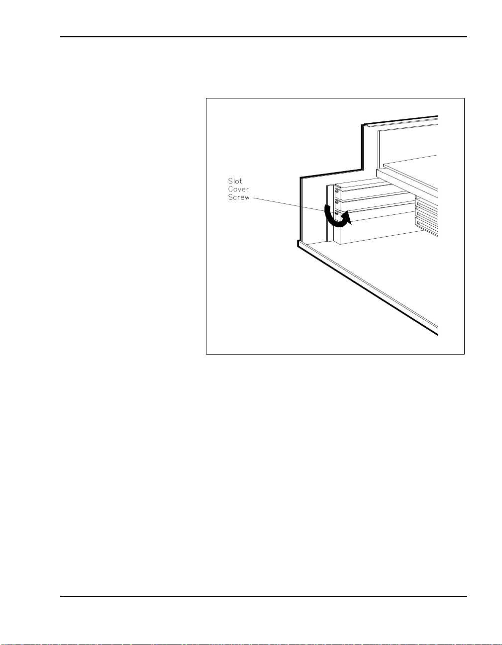
2. Locate and remove the screw that attaches the slot cover to the docking
station.
Removing the slot cover screw
3. Remove the slot cover.
4. Locate the expansion slot connectors inside the docking station.
5. Hold the board by its edges, component side up, and insert it into the slot.
If installing a full-size board, fit the board into the guide at the front of
the docking station.
Adding Options 4-9
Page 50
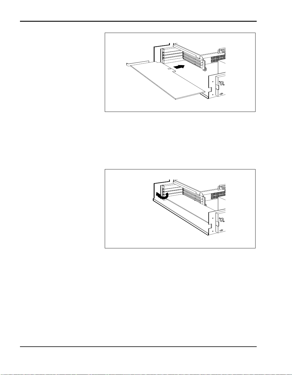
Aligning the board edge and connector
6. Press the board firmly until it is securely seated in the connector. You
may have to rock the board side-to-side.
7. Insert the screw to attach the board to the support bracket.
Securing the board
8. Repeat steps 2 through 7 to install a second or third expansion board.
9. Once you install the boards, continue as follows:
n To add drives, continue to the next section, “Data Storage Devices.”
n If you have no more options to install, replace the docking station
cover as described in “Cover Replacement” earlier in this chapter.
4-10 Adding Options
Page 51
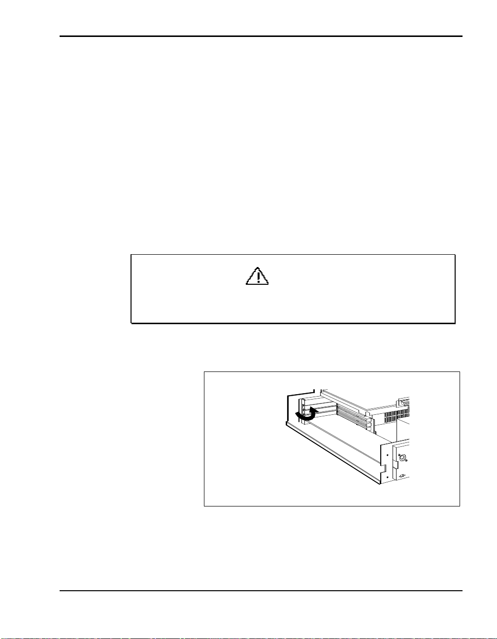
Removal
Follow these steps to remove an expansion board from the docking station.
1. Prepare for board removal as follows:
n Disconnect and remove the NEC Versa from the docking station.
n Turn off and unplug the docking station.
n Disconnect any peripheral devices connected to the docking station.
n Remove the docking station cover. See “Cover Removal” earlier in
this section for information on removing the cover.
n Position the docking station so you have access to the side where the
expansion slots are located.
CAUTION
Be careful not to drop anything into the docking station. Doing so
can damage the unit.
2. Remove the screw that attaches the board to the support bracket.
Removing the screw
Adding Options 4-11
Page 52
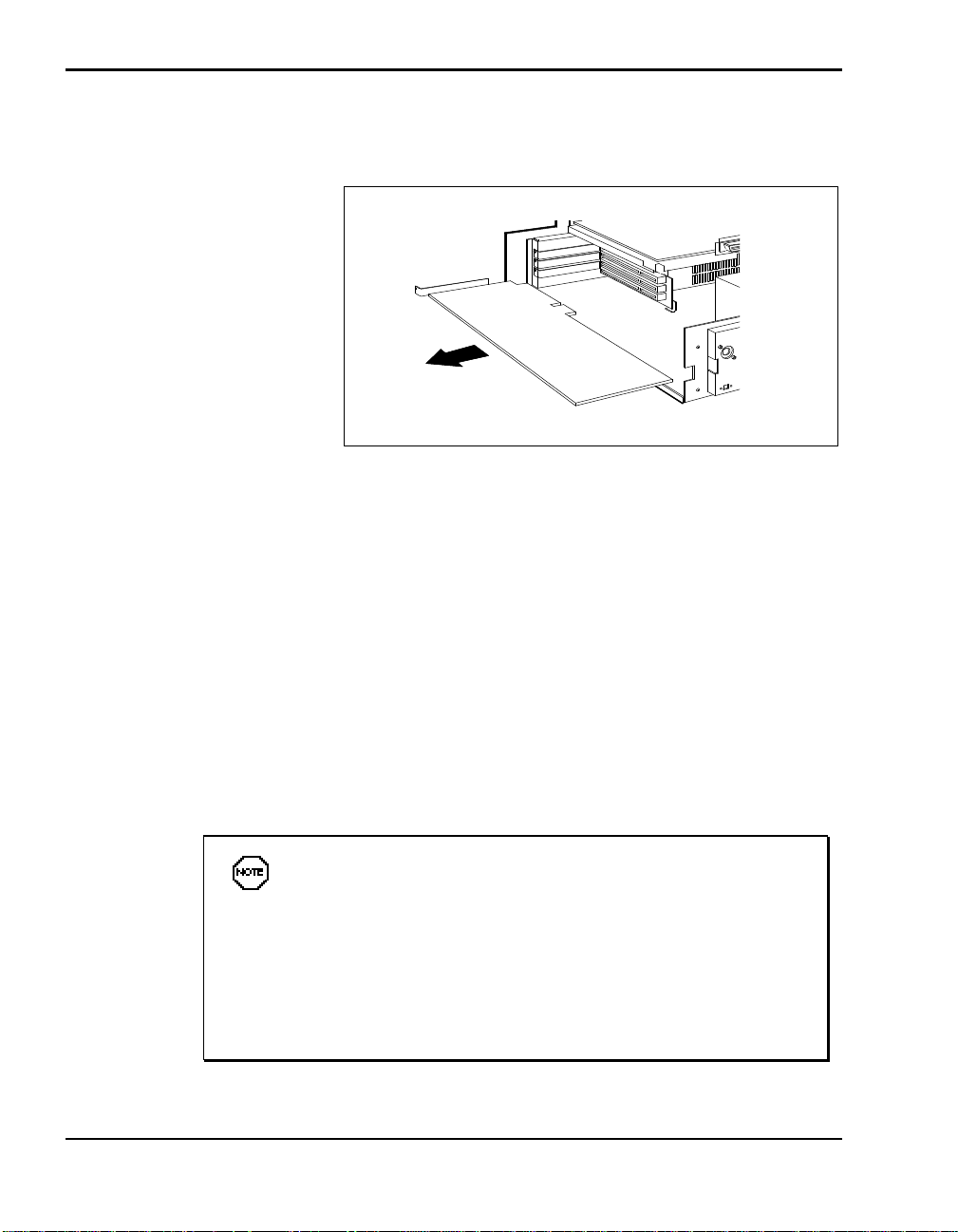
3. Hold the board by its edges and pull the board. You may need to rock the
board side-to-side to dislodge it from its connector.
4. Replace the docking station cover as described earlier in this chapter un-
der “Cover Replacement.”
DATA STORAGE DEVICES
The Docking Station 6000 has two bays for installing optional data storage
devices.
Removing the board
n A front bay provides external access to storage devices installed in it.
This bay accepts two standard 5 1/4-inch storage devices, including diskette, hard disk, tape, and CD-ROM drives.
n An internal bay provides space for one 3 1/2-inch hard disk drive.
NEC Versa series systems and the docking station support
only two diskette drives. Therefore, if you have more than two diskette drives installed in the NEC Versa and docking station, you can
only access two of them.
Some storage devices require that you provide a signal cable. For
example, to install a SCSI device, you need to purchase an optional
SCSI signal cable.
4-12 Adding Options
Page 53
Follow the instructions in the next section to prepare your drive for installation in the docking station.
Preparing the Drive
Read the documentation that came with the drive before beginning the installation procedure. Set any switches that need to be set on the drive.
If your drive comes with locking rails, do not use them. If the drive has
locking rails attached, remove them.
Installing Drives in the Front Bay
Use the following procedure to install a half-height diskette, tape, CD-ROM
or hard disk drive in the front drive bay. See “Preparing the Hard Disk
Drive” later in this chapter for hard disk drive preparation instructions.
Drive installation involves three basic procedures:
n Removing the drive cage.
n Attaching the drive(s) to the drive cage.
n Attaching power and signal cables to the drive.
n Finishing up (reinstalling the drive cage with the drive in the docking
station).
These procedures are described next.
Removing the Drive Cage
Prepare the docking station for drive installation by removing the drive cage
as follows.
Make sure docking station power is off, the NEC Versa is not
docked, peripheral devices are disconnected, and cables are detached from the docking station before beginning installation procedures.
1. Remove the docking station cover as described in “Cover Removal.”
WARNING
Adding Options 4-13
Page 54
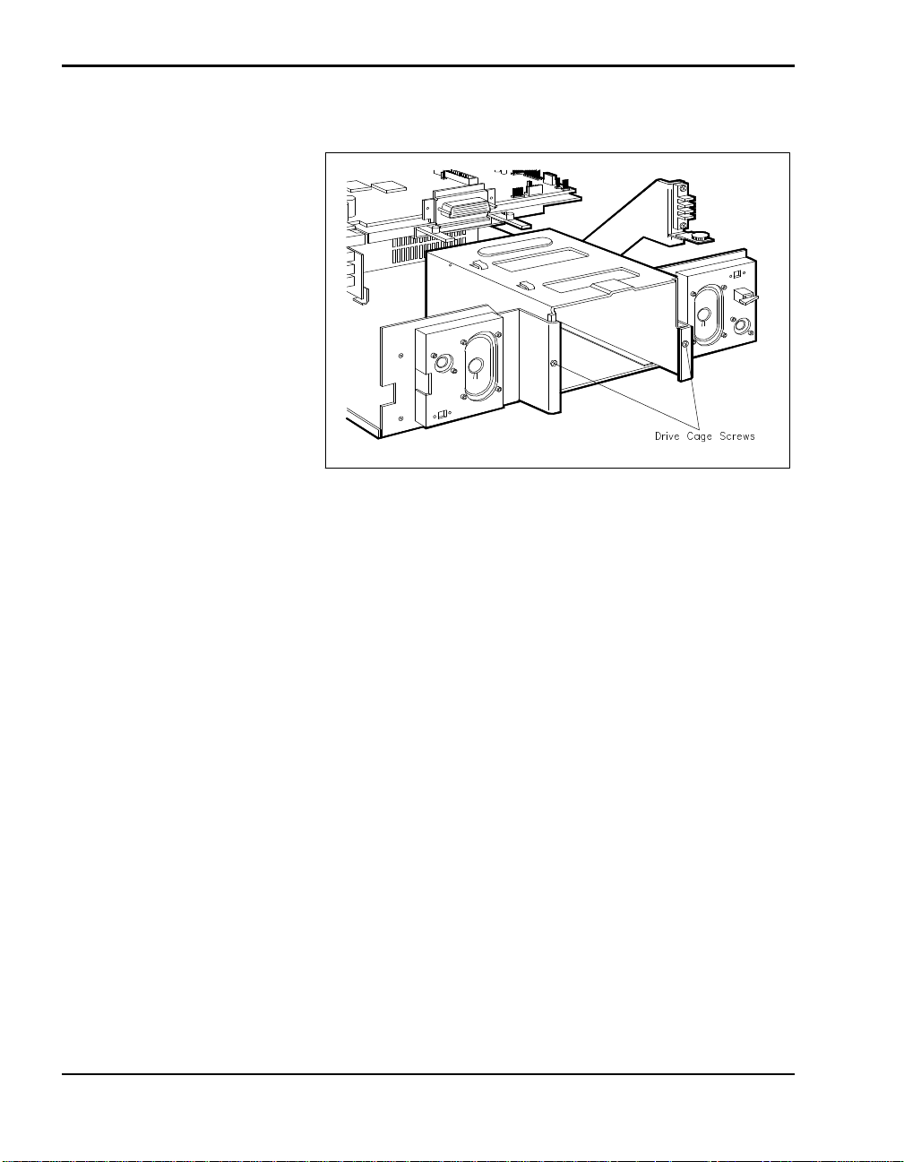
2. Locate and remove the screws on the drive cage.
Removing drive cage screws
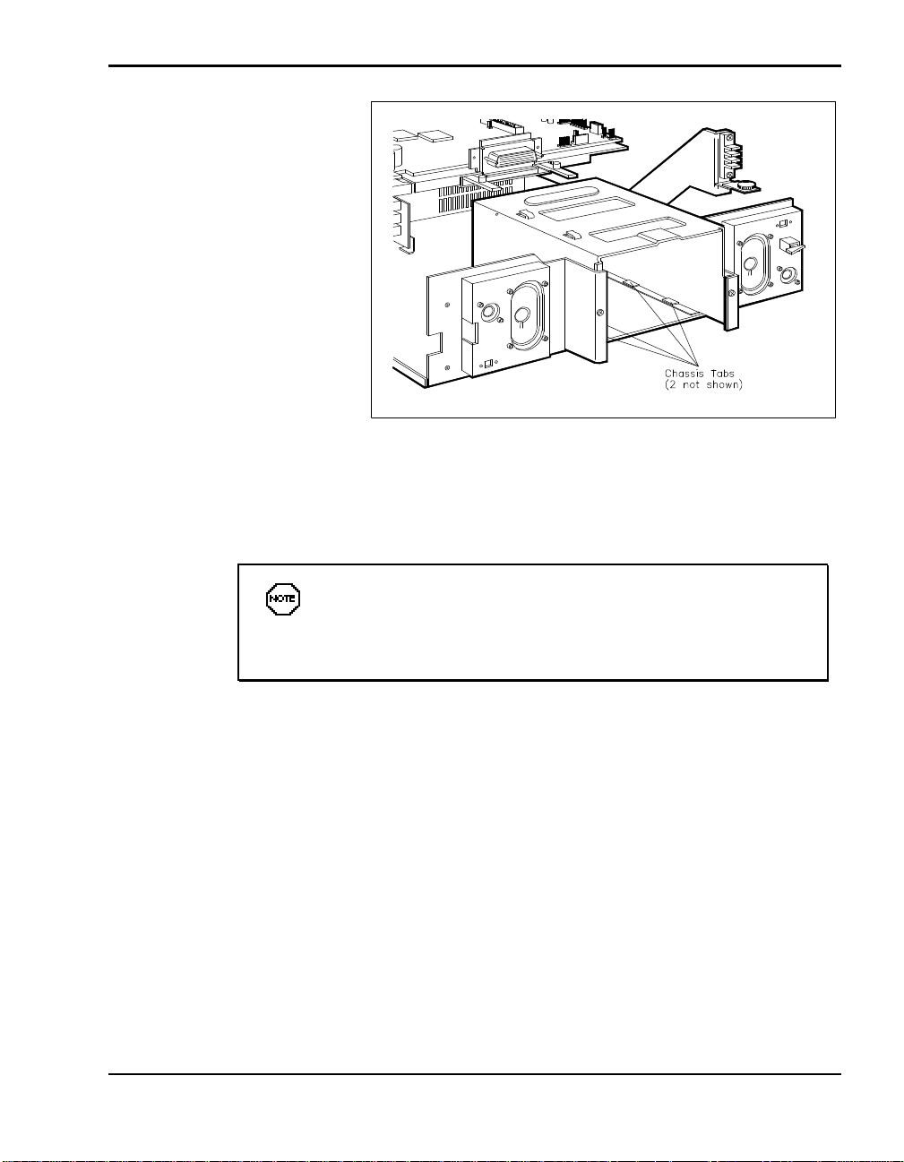
3. Slide the drive cage towards the back of the unit. Make sure the holes on
the bottom of the cage clear the tabs on the bottom of the docking station
chassis.
4. Lift the drive cage up and out of the system.
4-14 Adding Options
Page 55
Attaching the Drive to the Drive Cage
Attach the drive to the drive cage as follows.
Removing the drive cage
Before attaching the drive to the cage, make sure that any
switches on the drive are set properly. See the guide that came with
the drive for switch setting information.
1. Align the front of the drive with the front of one of the bays in the drive
cage.
Adding Options 4-15
Page 56
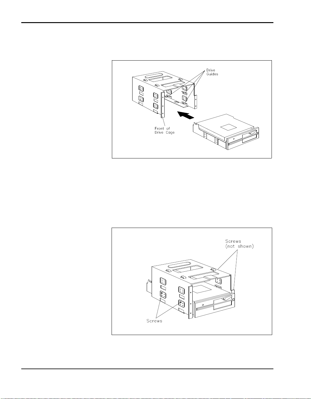
2. Slide the drive into the drive cage. Be sure the drive is seated on the
guides within the cage.
Sliding the drive into the cage
3. Locate the screw holes on the side of the drive cage and align them with
the screw holes on the side of the drive.
4. Using the screws that came with the drive, secure the drive to the drive
4-16 Adding Options
cage.
Securing the drive
Page 57
Attaching the Cables
Attach drive cables as follows.
When connecting cables, align the cable connector with the
drive connector and position the red edge of the cable as shown in
the figures.
Taking care not to bend any pins, press the cable connector firmly
onto the pins.
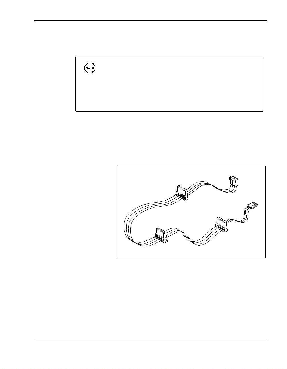
1. Place the drive cage close to the docking station for easy access to the
connectors on the docking station interface board.
2. Look in the package of cables that came with the docking station and lo-
cate drive power cable.
Drive power cable
3. Connect the power cable to the docking station interface board.
Adding Options 4-17
Page 58
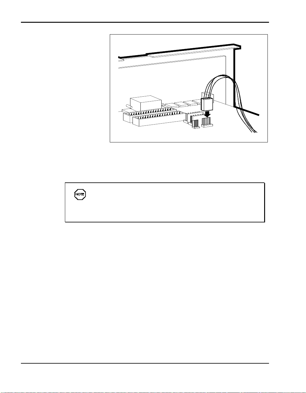
Connecting the power cable
4. Attach the cables for your drive type as follows.
When installing SCSI drives, you must purchase an optional
SCSI cable. If you are installing Plug and Play SCSI devices, purchase a cable that comes with a terminated connector.
n For diskette drives:
Look in the package of cables and find the diskette drive signal
cable.
4-18 Adding Options
Page 59
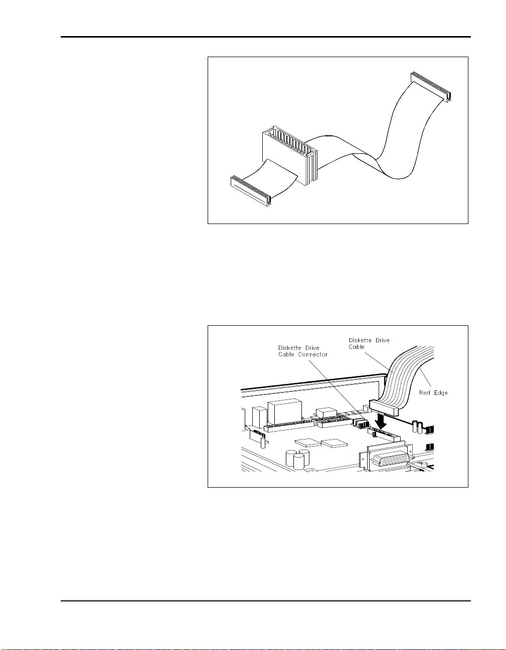
Diskette Drive Cable
Connect the diskette drive signal cable to the docking station in-
terface board as shown in the following figure.
Position the red edge as shown.
Connecting the diskette drive signal cable
Position the red edge of the signal cable as shown in the following
figure and connect the cable to the drive.
Adding Options 4-19
Page 60
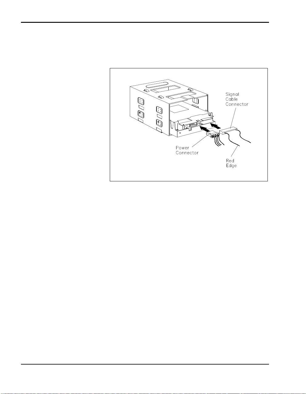
Connect a large or small power cable connector to the drive (con-
nector size depends on the drive you are installing). Power connectors are keyed to fit only one way.
Connecting the diskette drive signal cable
n For IDE drives
Locate the IDE cable in the bag of cables that came with the docking
station. The cable looks similar to the following.
4-20 Adding Options
Page 61
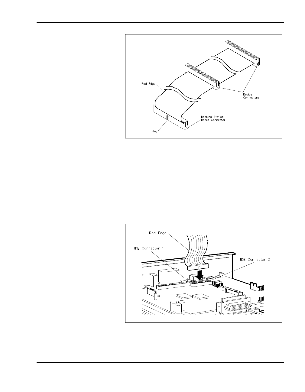
IDE Cable
Locate the cable connector to attach to the docking station
board. The connector has a projection that acts as a key on one
side.
Align the cable connector and the key with the connector on the
board and press firmly to attach them.
Position the red edge of the cable as shown.
Connecting the cable to the docking station board
Adding Options 4-21
Page 62
CAUTION
When connecting the IDE cable, be sure to use the correct cable
connector. Using the wrong connector can cause your system to
malfunction and damage the cable.
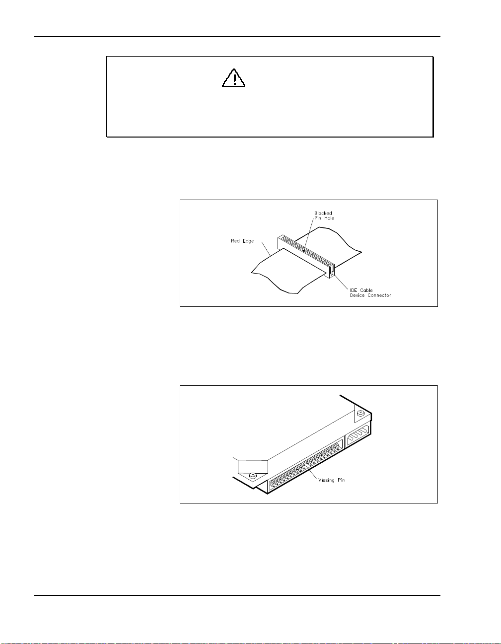
On the IDE cable, pick a connector to attach to your IDE device.
Note the location of the blocked hole in the connector.
Blocked pin hole
4-22 Adding Options
On the IDE device, locate the gap in the cable port. It looks like a
space with a missing pin.
Missing pin on IDE device connector
Page 63
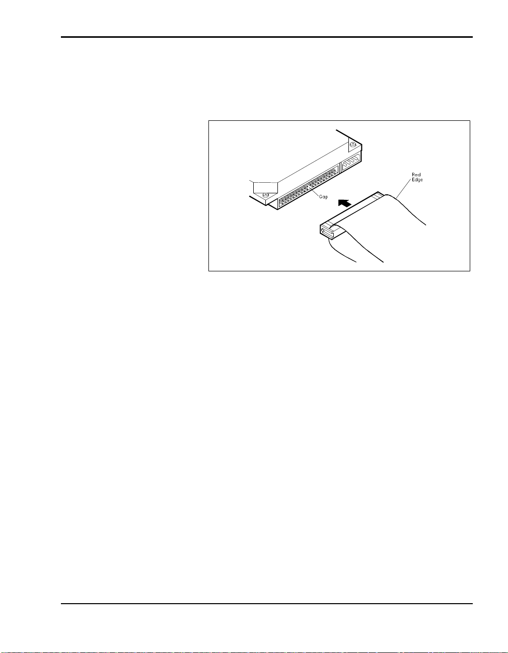
Align the gap on the device port with the blocked pin hole on the
cable connector and connect them.
Press firmly to secure the attachment.
Connecting the IDE cable to the device
On some IDE drives, the connector is reversed. The gap is in the
top row of pins instead of the bottom row. In this case, turn the
cable over so that the red edge is on the opposite side of the one
pictured.
If you are installing an IDE device with audio features (like a
CD-ROM reader), connect the audio cable as follows:
Locate the audio cable in the bag of cables that came with the
docking station.
Adding Options 4-23
Page 64
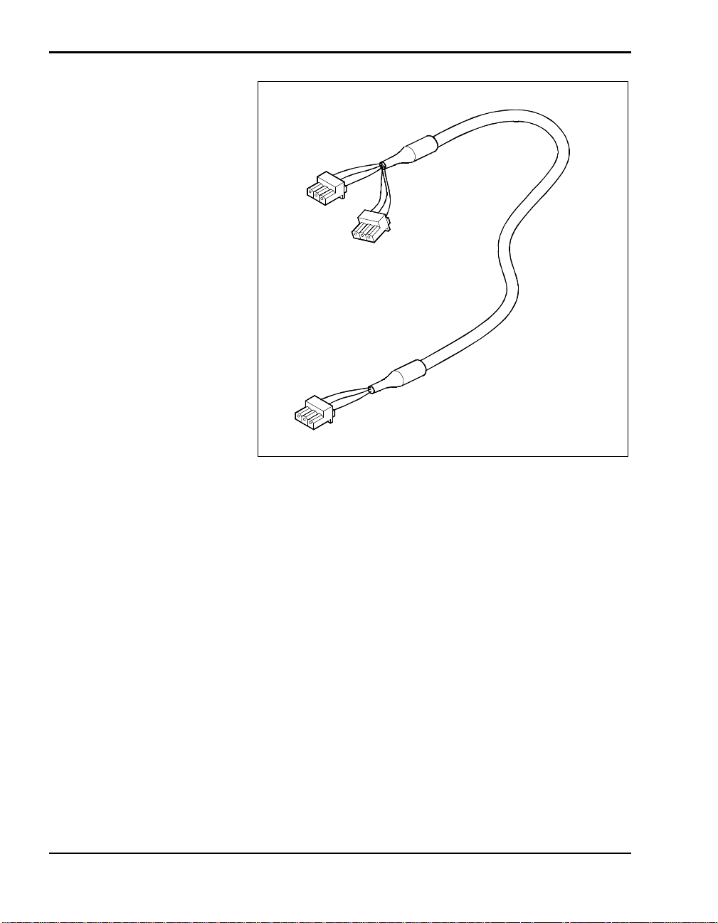
Audio Cable
Attach the audio cable to the docking station interface board as
shown in the following figure.
4-24 Adding Options
Page 65
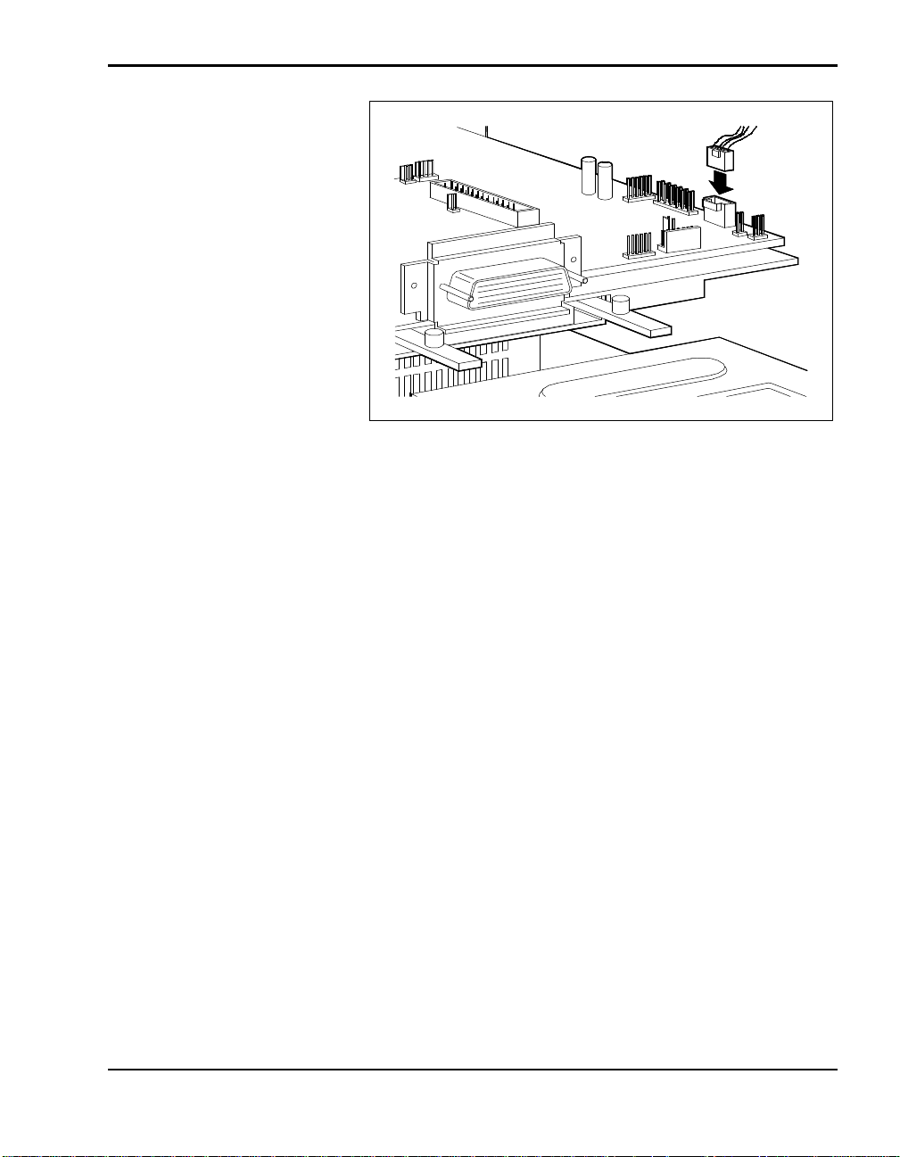
Connecting the audio cable
Connect a large or small power cable connector to the drive (con-
nector size depends on the drive you are installing). Power connectors are keyed to fit only one way.
The audio cable comes with two connectors. Pick the one that is
appropriate for your drive type.
Adding Options 4-25
Page 66
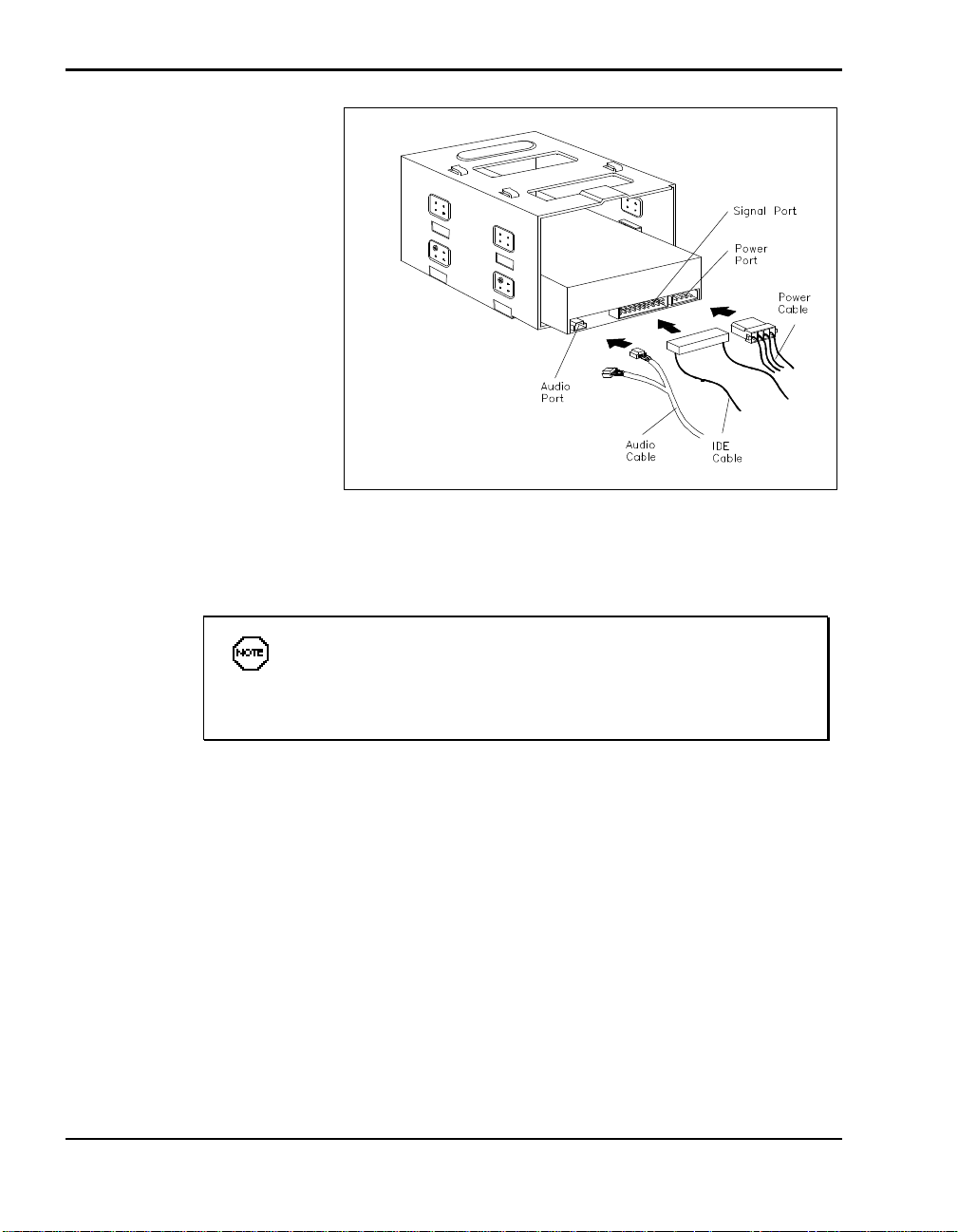
Connecting the IDE and power cables
n For SCSI drives
4-26 Adding Options
To install SCSI devices, you must purchase an optional SCSI
cable. If you are installing Plug and Play SCSI devices, purchase a
cable that comes with a terminated connector.
Locate your optional SCSI cable. It should look similar to the one
shown in the following figure.
Page 67
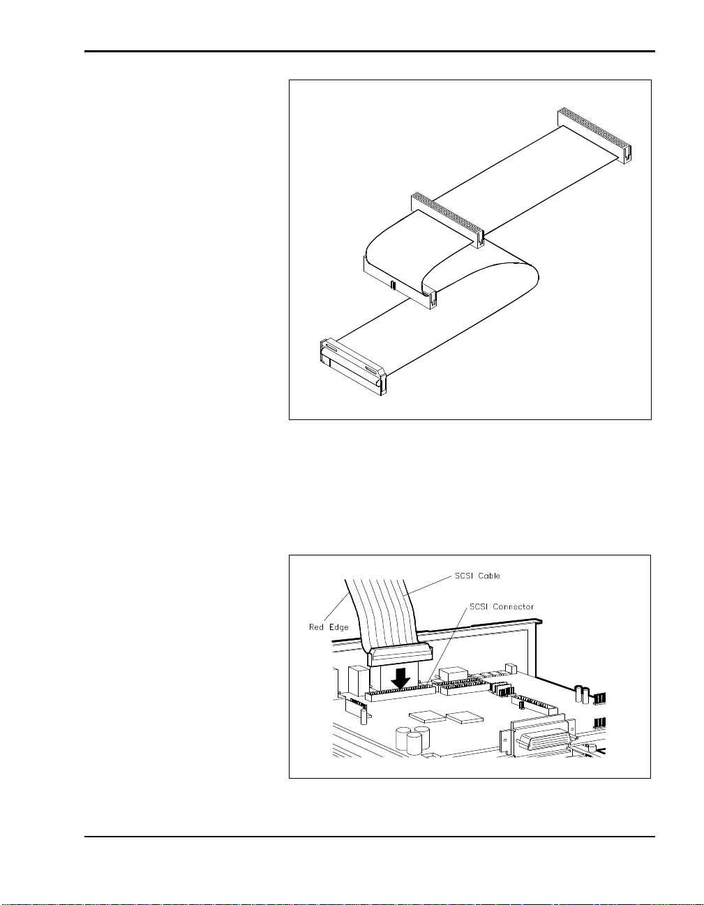
Optional SCSI signal cable
Locate the SCSI cable connector on the docking station interface
board.
Connect the SCSI signal cable to the interface board. (Connectors
are keyed to fit only one way.)
Connecting the SCSI cable to the interface board
Adding Options 4-27
Page 68
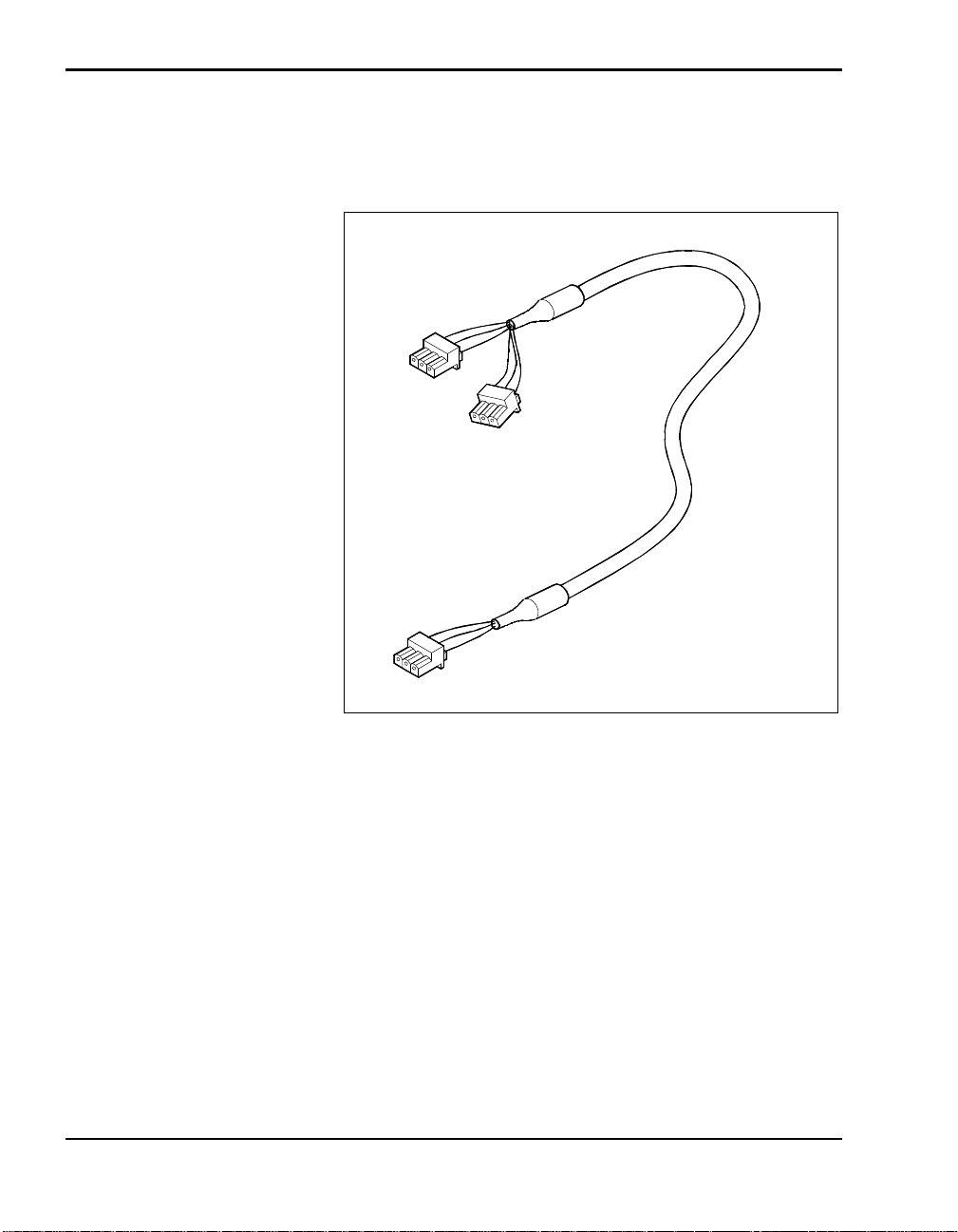
If you are installing a SCSI device with audio features (like a
CD-ROM reader), connect the audio cable as follows:
Locate the audio cable that came with the docking station.
Audio cable
Attach the audio cable to the docking station interface board.
4-28 Adding Options
Page 69
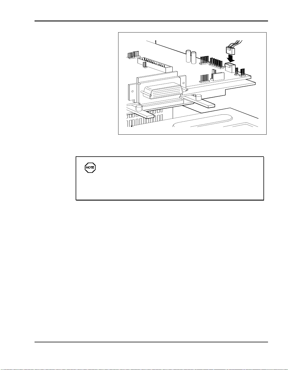
Connecting the audio cable
When installing SCSI devices, use the end connector on the
cable first. Attach the next SCSI device to next connector on the cable. (Do not skip connectors when attaching more than one SCSI
device.)
Connect the cables to the back of the drive. (See the documenta-
tion that came with the drive exact connector locations. Locations
vary depending on model.)
The audio cable comes with two connectors. Pick the one that is
appropriate for your drive type.
Adding Options 4-29
Page 70
Finishing Up
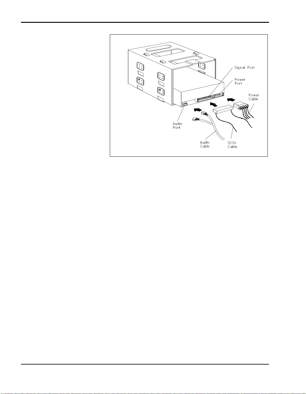
Connecting SCSI cables
5. To complete drive installation, go to “Finishing Up.”
Finish up drive installation as follows.
1. Locate the tabs on the bottom of the docking station chassis.
2. Position the drive cage a little behind the tabs and lower it into the unit.
3. Slide the drive cage forward until the tabs slide into the matching holes
on the bottom of the drive cage.
4. Replace the two screws that secure the drive cage in the docking station.
4-30 Adding Options
Page 71
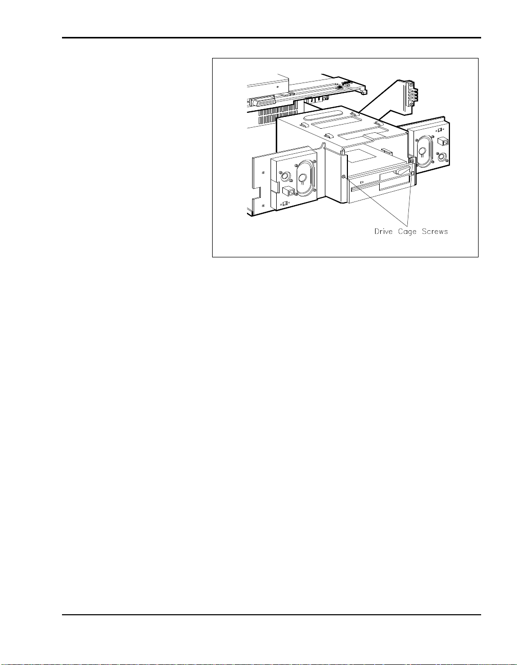
Replacing drive cage screws
5. If you installed a drive that requires external access, remove the drive
slot cover from the docking station cover as follows:
n Locate the drive slot cover tabs inside the docking station cover.
n Gently push the tabs out until you can release the cover.
n Remove the slot cover and store it in a safe place for possible future
use.
Adding Options 4-31
Page 72
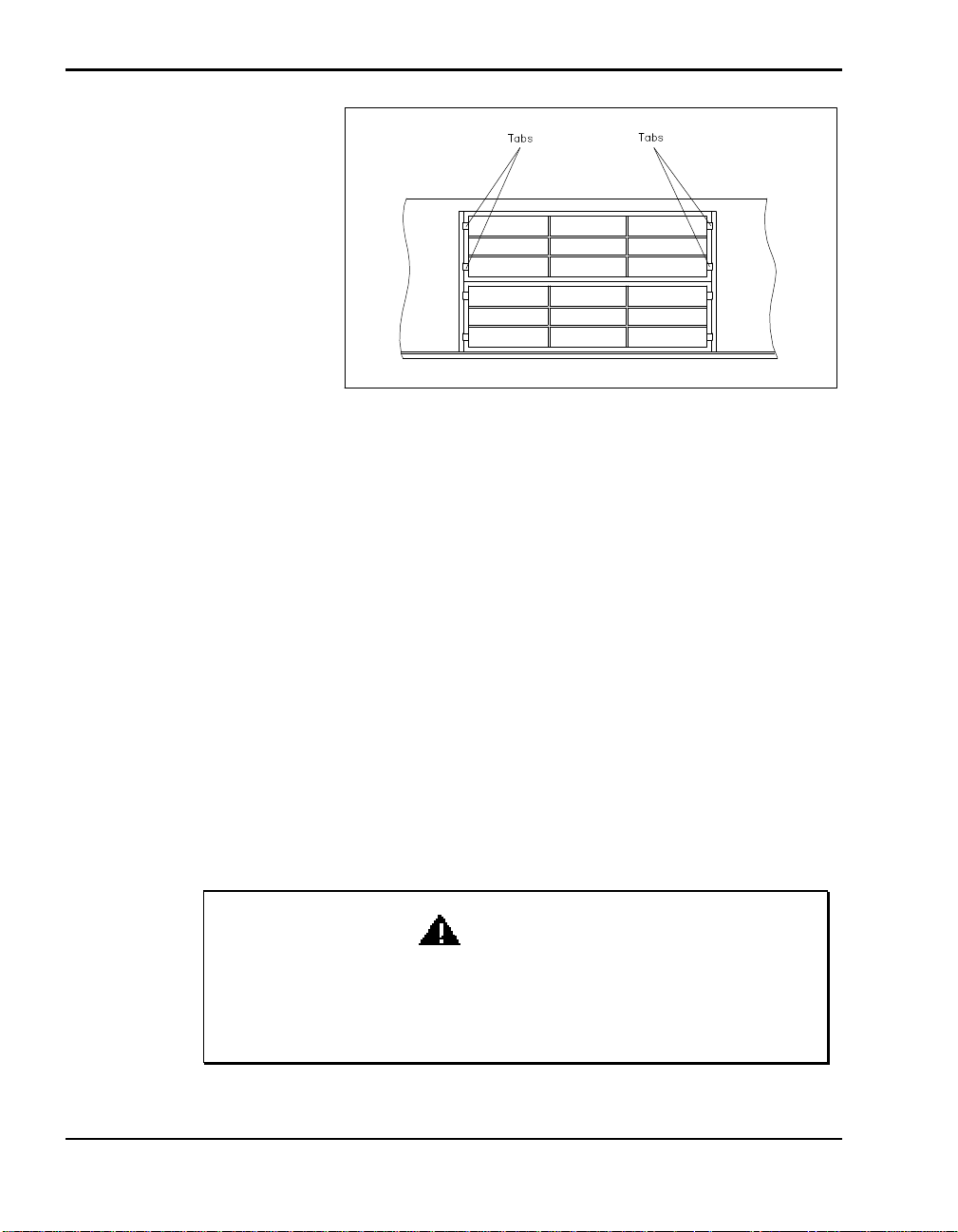
6. Being careful to move cables out of the way to prevent crushing them,
replace the docking station cover as described in “Cover Replacement.”
Hard Disk Drives
Installing a hard disk drive involves the following steps:
n Preparing the hard disk drive
Removing the drive slot cover
n Setting your hard disk drive to slave or master as appropriate
n Installing the drive
n Connecting cables
n Finishing up.
This section describes how to install a hard disk drive in the internal hard
disk drive bay in the docking station.
4-32 Adding Options
WARNING
Make sure docking station power is off, the NEC Versa is not
docked, peripheral devices are disconnected, and cables are detached from the docking station before beginning installation procedures.
Page 73
Preparing the Hard Disk Drive
The NEC Versa Docking Station 6000 has built-in IDE and SCSI controllers. However, some hard disk drives require that you install a controller
board. Before installing a drive that requires a controller board, install the
board as described in “Expansion Boards.”
See the documentation that comes with the drive for specific
cabling instructions.
Before starting the installation , check the following.
n The interface of your hard disk must match the interface of the hard disk
controller. For example, an IDE hard disk requires an IDE hard disk
controller.
If you are installing another controller board, you must disable
the built-in IDE. This is done through the Setup utility that comes
with your NEC Versa system. See your NEC Versa series user's
guide for more information.
n If you are installing a SCSI drive, you must purchase an optional SCSI
cable. If you are installing a Plug and Play SCSI device for use with a
Plug and Play system, make sure the SCSI cable comes with a terminated
connector.
n Follow any pre-installation instructions in the guide that comes with the
drive, such as setting jumpers or switches.
Specifying Master and Slave Drives
IDE drives must be set correctly as the first (master) or second (slave) drive.
Check the jumper settings on the drive before beginning the installation
procedure.
Only one drive can be identified as the master drive. If you plan to use the
NEC Versa IDE drive when docked, set the docking station IDE drive to the
slave setting.
Adding Options 4-33
Page 74
Installing the Drive
Follow these instructions to install a hard disk drive in the internal drive bay
of the docking station.
Make sure docking station power is off, the NEC Versa is not
docked, all peripheral devices are disconnected, and all power cables are detached from the docking station before starting this procedure.
1. Remove the docking station cover as described in “Cover Removal.”
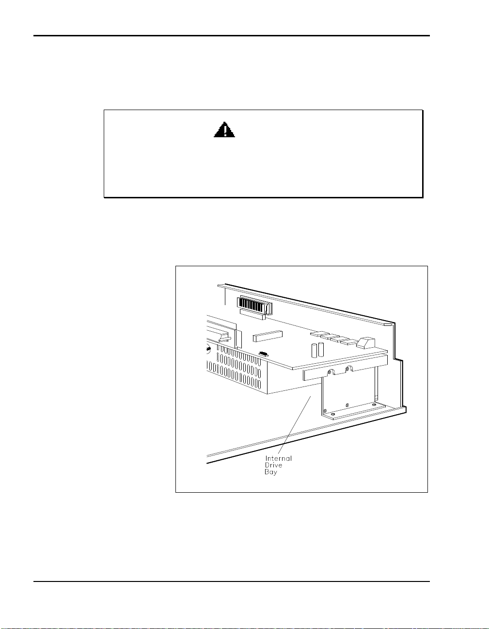
2. Locate the internal hard disk drive bay.
WARNING
Locating the internal drive bay
4-34 Adding Options
Page 75
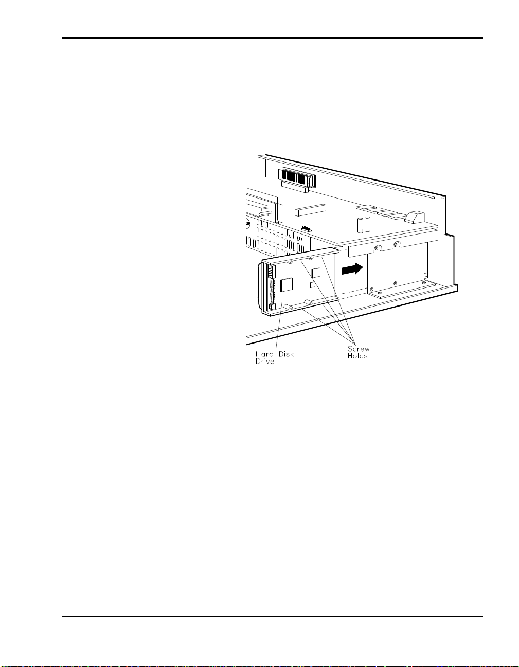
3. Align the hard disk drive so that its cable connectors face the front of the
docking station. Make sure the screw holes on the hard disk drive face
the drive bracket in the docking station.
4. Insert the drive into the drive bay.
Aligning and installing the drive
5. Align the screw holes on the drive with those on the bracket.
Adding Options 4-35
Page 76
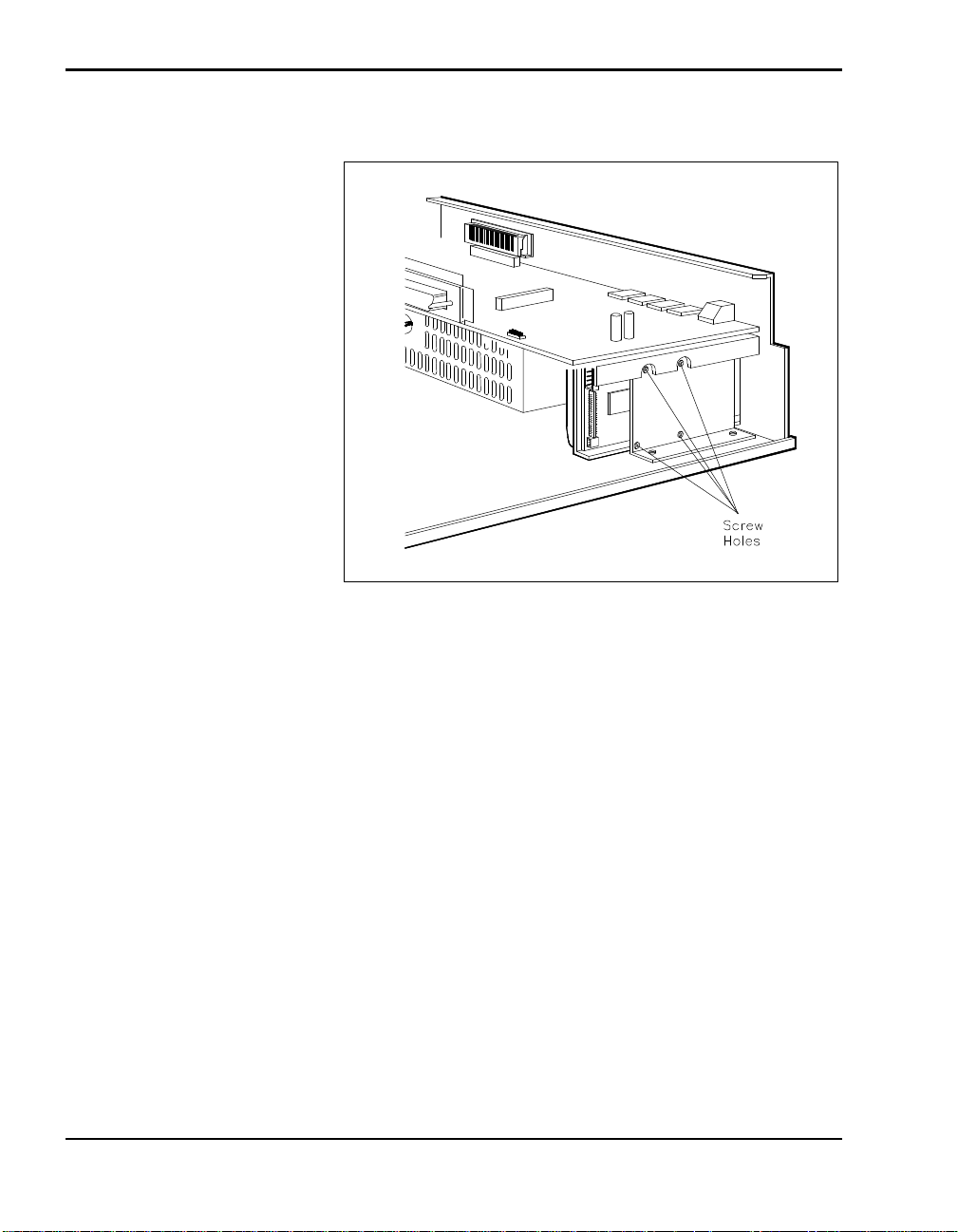
6. Use four screws and attach the disk drive to the guide.
Attaching the drive to the bracket
7. To continue, go to the appropriate cabling section:
n See “Attaching IDE Drive Cables” for IDE drive installations.
n See “Attaching SCSI Drive Cables” for SCSI drive installations.
Attaching IDE Drive Cables
Attach IDE drive cables as follows. The connectors are keyed to fit only one
way.
1. Locate the IDE cable in the bag of cables that came with the docking
station. The cable looks similar to the following.
4-36 Adding Options
Page 77
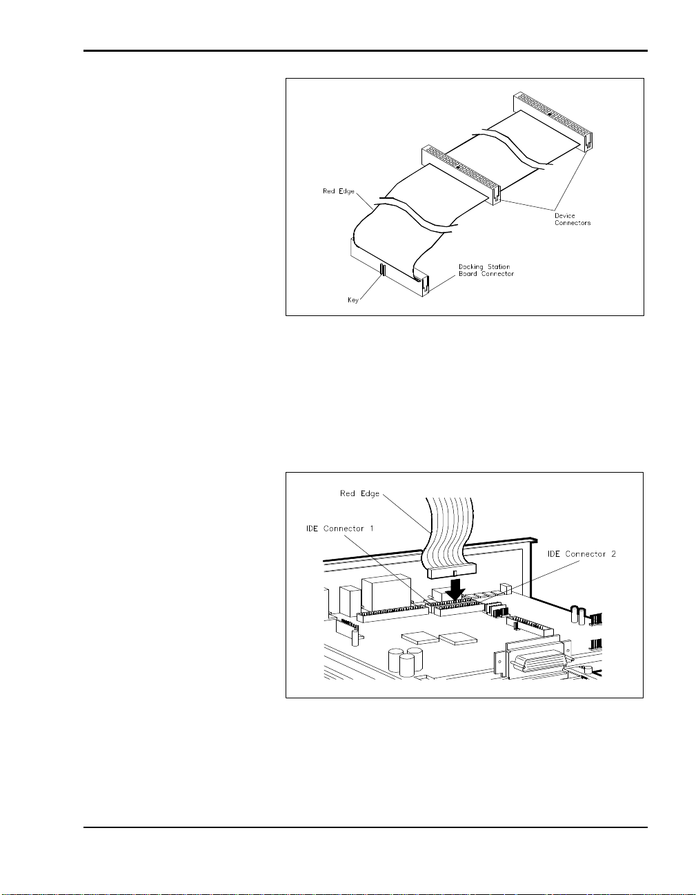
IDE Cable
2. Locate the cable connector to attach to the docking station board. The
connector has a projection that acts as a key on one side.
3. Align the cable connector and the key with the connector on the board
and press firmly to attach them.
Connecting the cable to the docking station board
Adding Options 4-37
Page 78
CAUTION
When connecting the IDE cable, be sure to use the correct cable
connector. Using the wrong connector can cause your system to
malfunction and damage the cable.
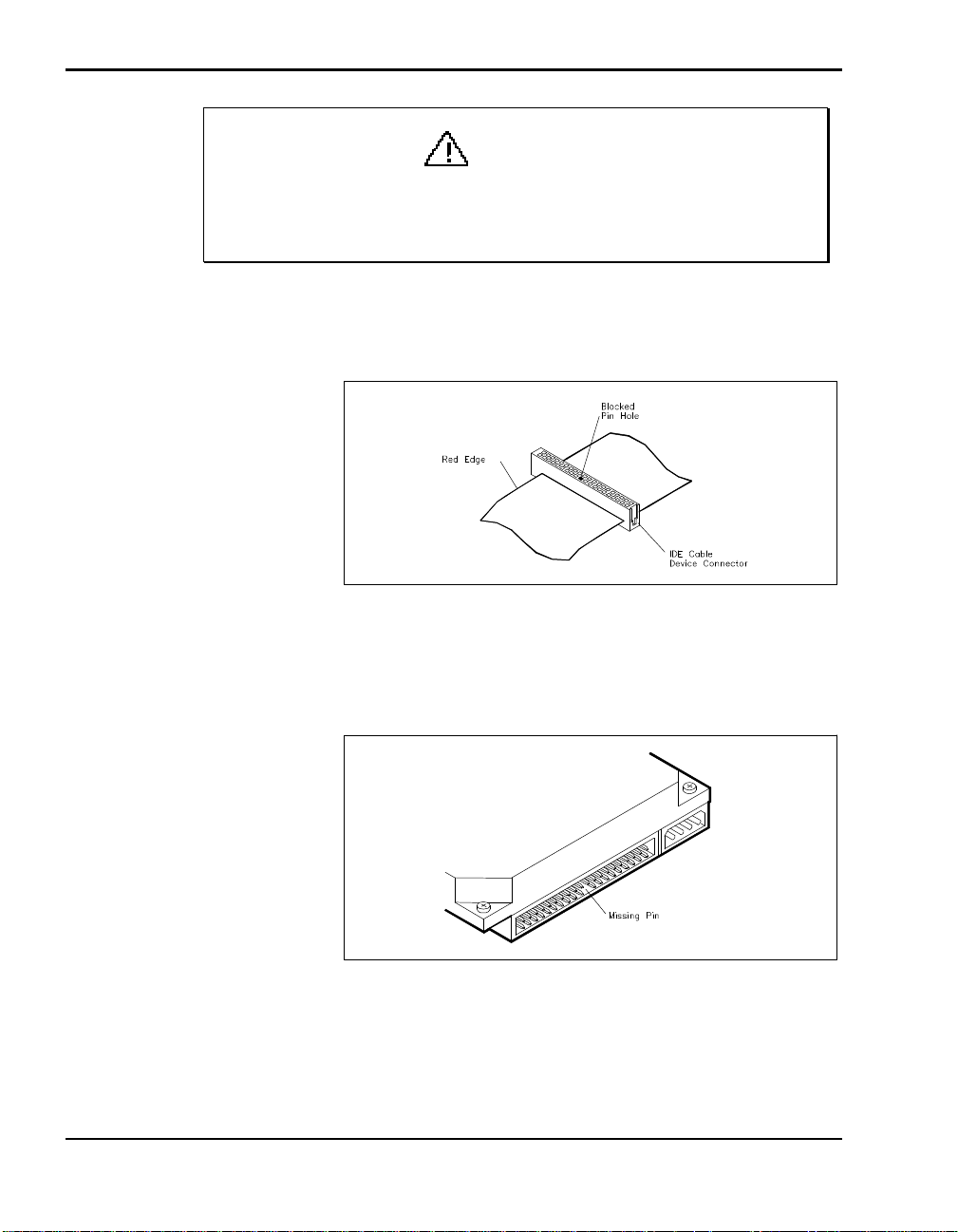
4. On the IDE cable, pick a connector to attach to your IDE device. Note
the location of the blocked hole in the connector.
Blocked pin hole
5. On the IDE device, locate the gap in the cable port. It looks like a space
6. Align the gap on the device port with the blocked pin hole on the cable
4-38 Adding Options
with a missing pin.
Missing pin on IDE device connector
connector and connect them.
Page 79
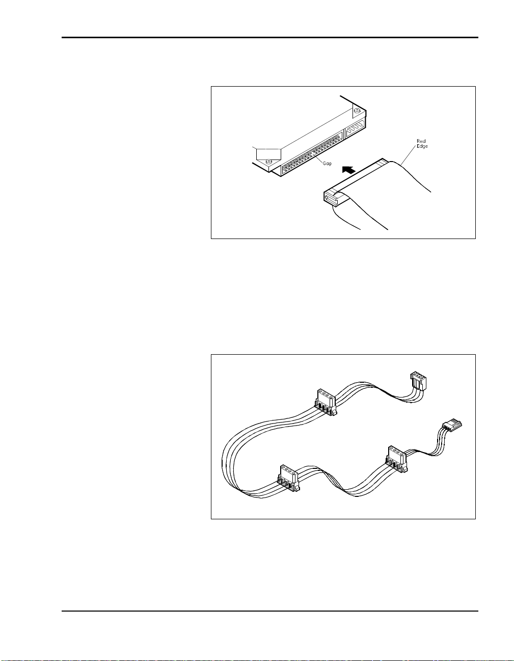
7. Press firmly to secure the attachment.
Connecting the IDE cable to the device
On some IDE drives, the connector is reversed. The gap is in the top row
of pins instead of the bottom row. In this case, turn the cable over so that
the red edge is on the opposite side of the one pictured.
8. Locate the power cable that came in the cable accessories bag.
The power cable
9. Connect the cable to the interface board. Power connectors are keyed to
fit in only the correct position.
Adding Options 4-39
Page 80
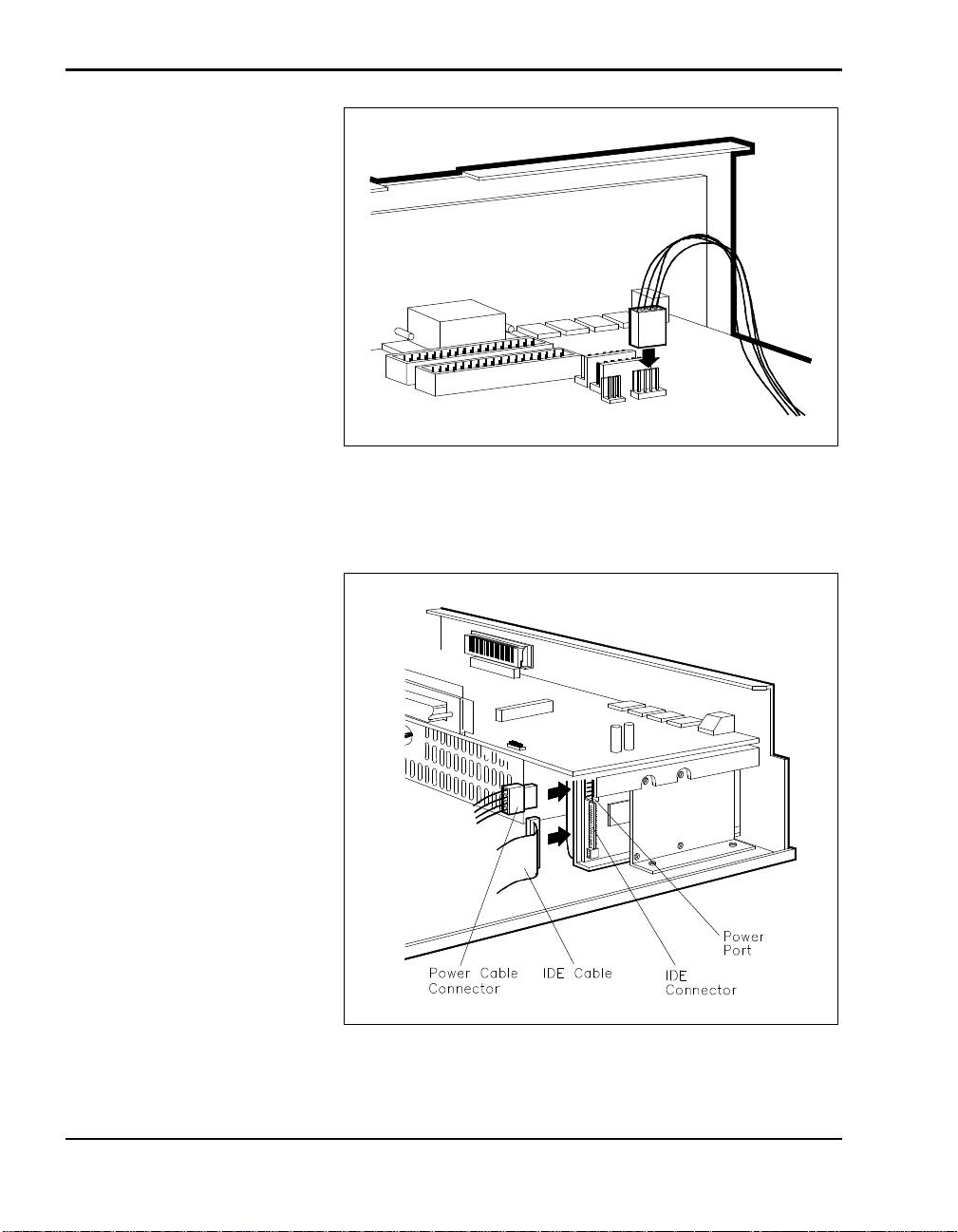
Connecting the power cable to the interface board
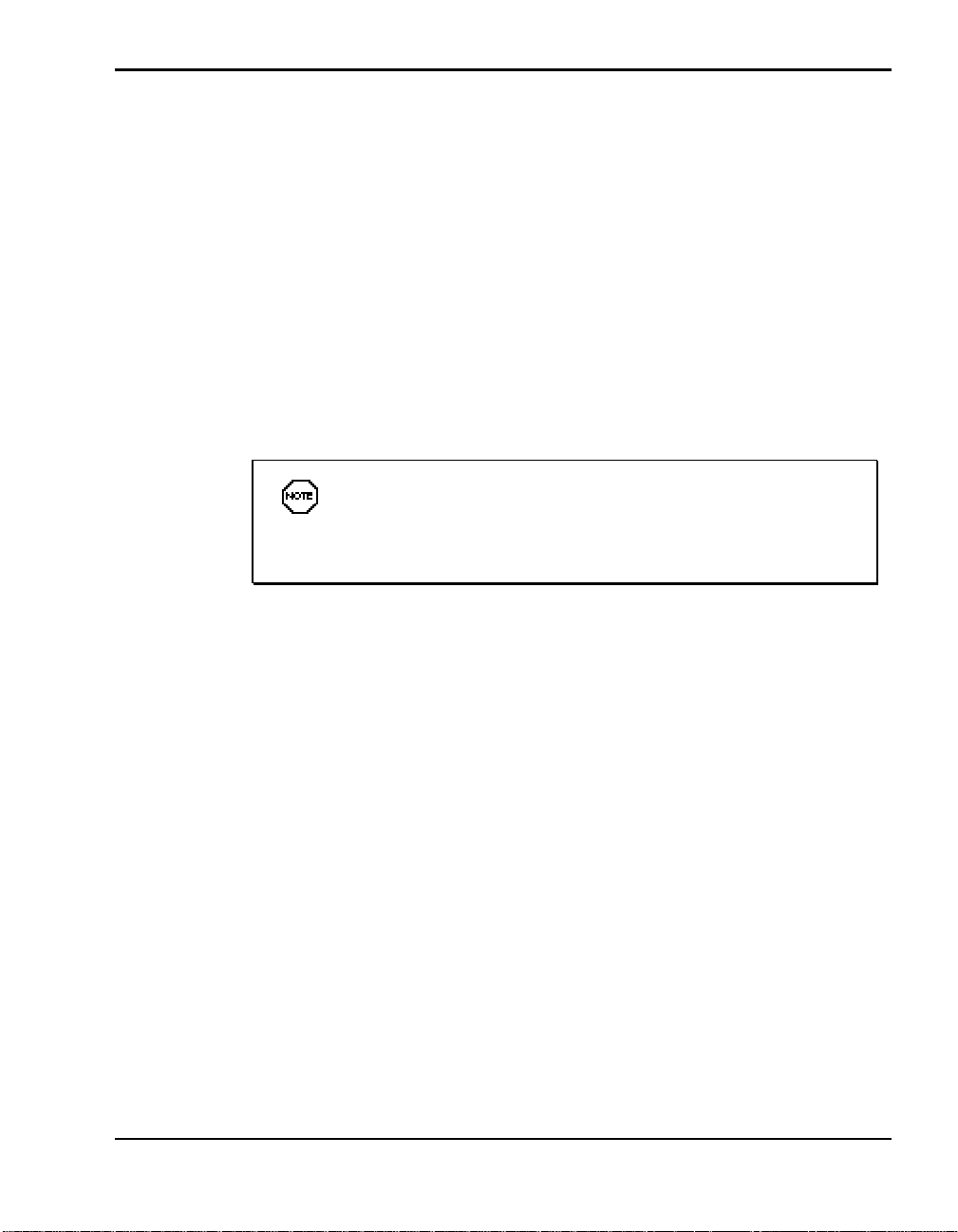
10. Connect the cables to the drive.
Connecting the cables to the drive
4-40 Adding Options
Page 81
11. If you have nothing else to install, replace the docking station cover as
described in “Cover Replacement.”
12. Proceed as follows:
n If you have a Plug and Play system, simply dock the NEC Versa and
reboot your system. The NEC Versa automatically detects the new
drive.
n If you do not have a Plug and Play system, run Setup to set your
new configuration.
Attaching SCSI Drive Cables
Attach SCSI drive cables as follows.
To install a SCSI drive, you must purchase an optional SCSI
cable. If you are installing Plug and Play SCSI drive, purchase a cable that comes with a terminated connector.
1. Locate the SCSI cable connector on the docking station interface board.
The cable should look similar to the one shown in the following figure.
Adding Options 4-41
Page 82
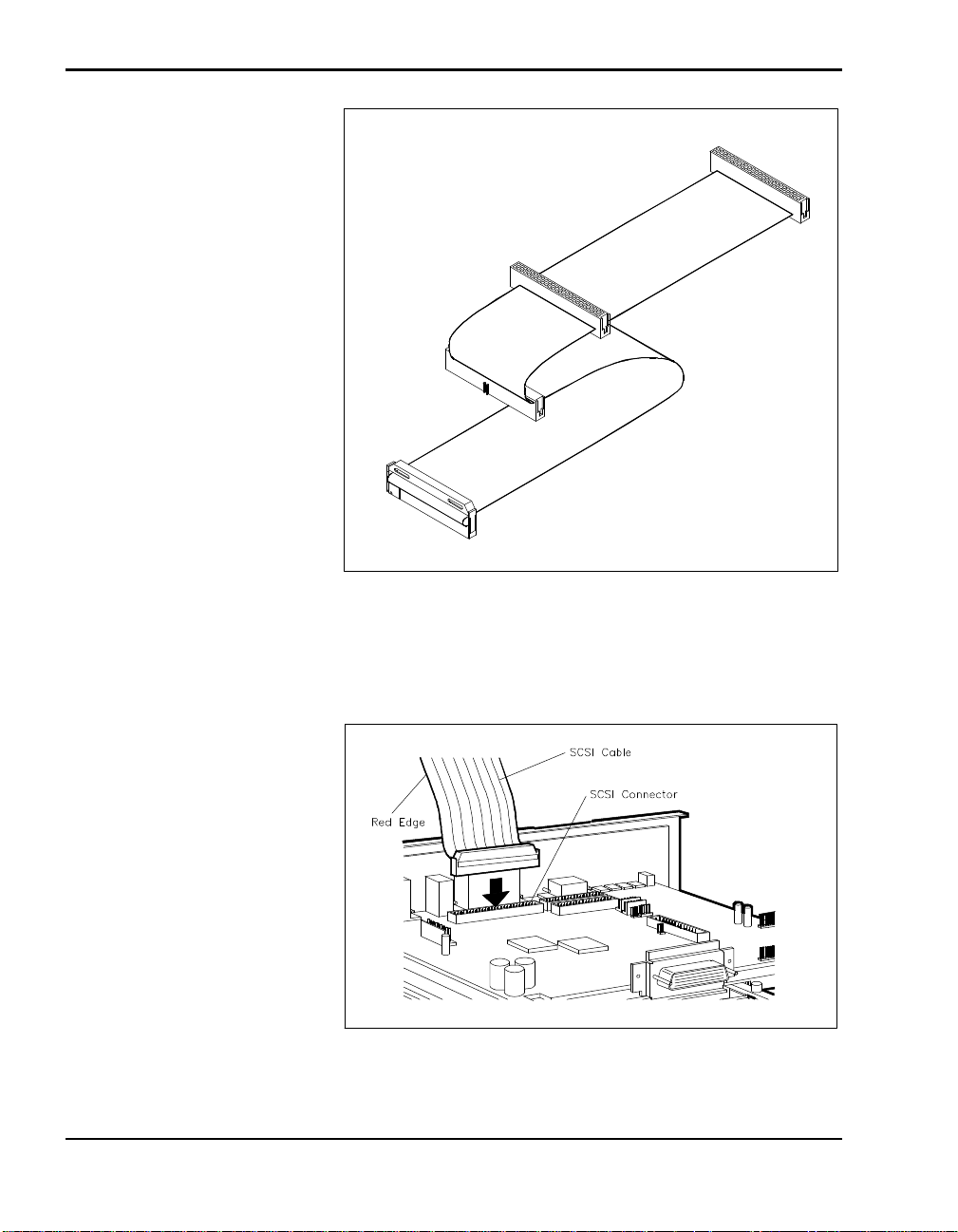
Optional SCSI cable
2. Attach the connector on the SCSI cable to the connector on the board.
4-42 Adding Options
The connectors are keyed to fit in only one position.
Attaching the SCSI cable
Page 83
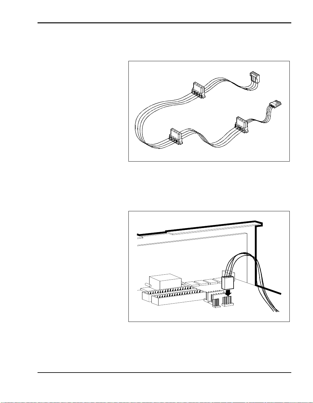
3. Locate the device power cable that came with the docking station. It
looks similar to the one shown in the following figure.
Power cable
4. Attach the power cable to the docking station interface board as shown in
the next figure.
Attaching the power cable to the docking station board
Adding Options 4-43
Page 84
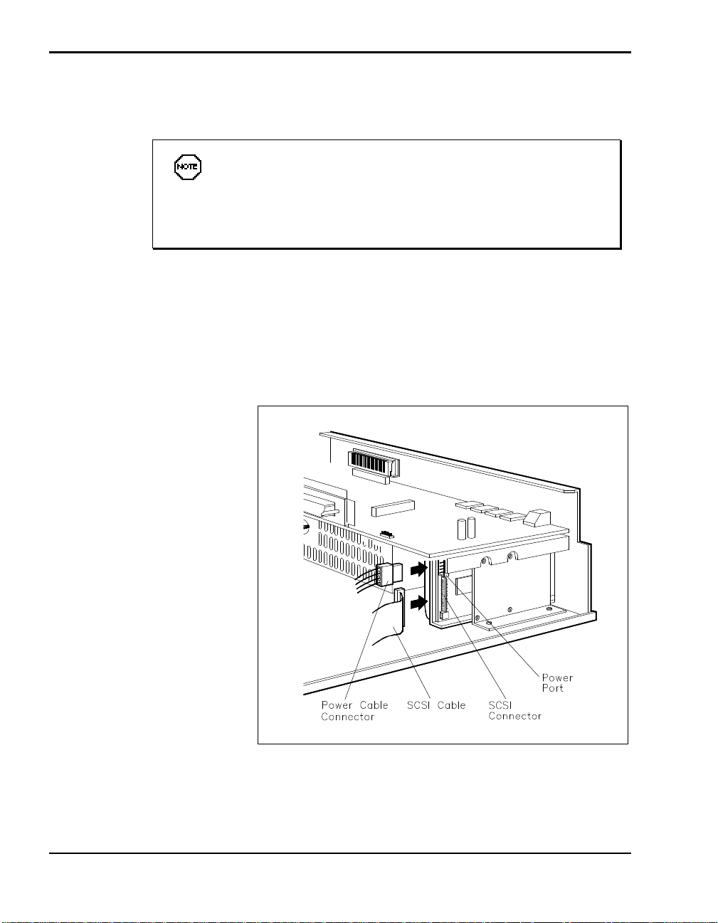
5. Align the cable connector with the hard disk drive connector as shown.
(The connectors are keyed to fit only one way.)
When installing SCSI devices, use the end connector on the
cable first. Attach the next SCSI device to next connector on the cable. (Do not skip connectors when attaching more than one SCSI
device.)
6. Taking care not to bend any pins, press the cable connector firmly onto
the pins. The connectors are keyed to fit in only the correct position.
7. Attach the appropriate power cable connector to the power connector on
the hard disk. Power connectors are keyed to fit only in the correct
position.
Attaching the SCSI cable to the drive
4-44 Adding Options
Page 85

8. If you have nothing else to install, replace the docking station cover as
described in “Cover Replacement.”
9. Proceed as follows:
n If you have a Plug and Play system, simply dock the NEC Versa and
reboot your system. The NEC Versa automatically detects the new
drive.
n If you do not have a Plug and Play system, run Setup to set your new
configuration.
VERSABAY II ADAPTER INSTALLATION
Installing the VersaBay II Adapter in the Docking Station 6000 involves the
following procedures:
n Removing the docking station cover. (See “Cover Removal” earlier in
this chapter.)
n Removing the drive cage.
n Connecting the adapter to the drive cage.
n Attaching the cables.
n Finishing up, which involves removing the slot cover and replacing the
docking station cover.
These procedures are described in the sections that follow.
Removing the Drive Cage
Remove the docking station drive cage as follows.
1. Locate and remove the two screws on the drive cage.
Adding Options 4-45
Page 86
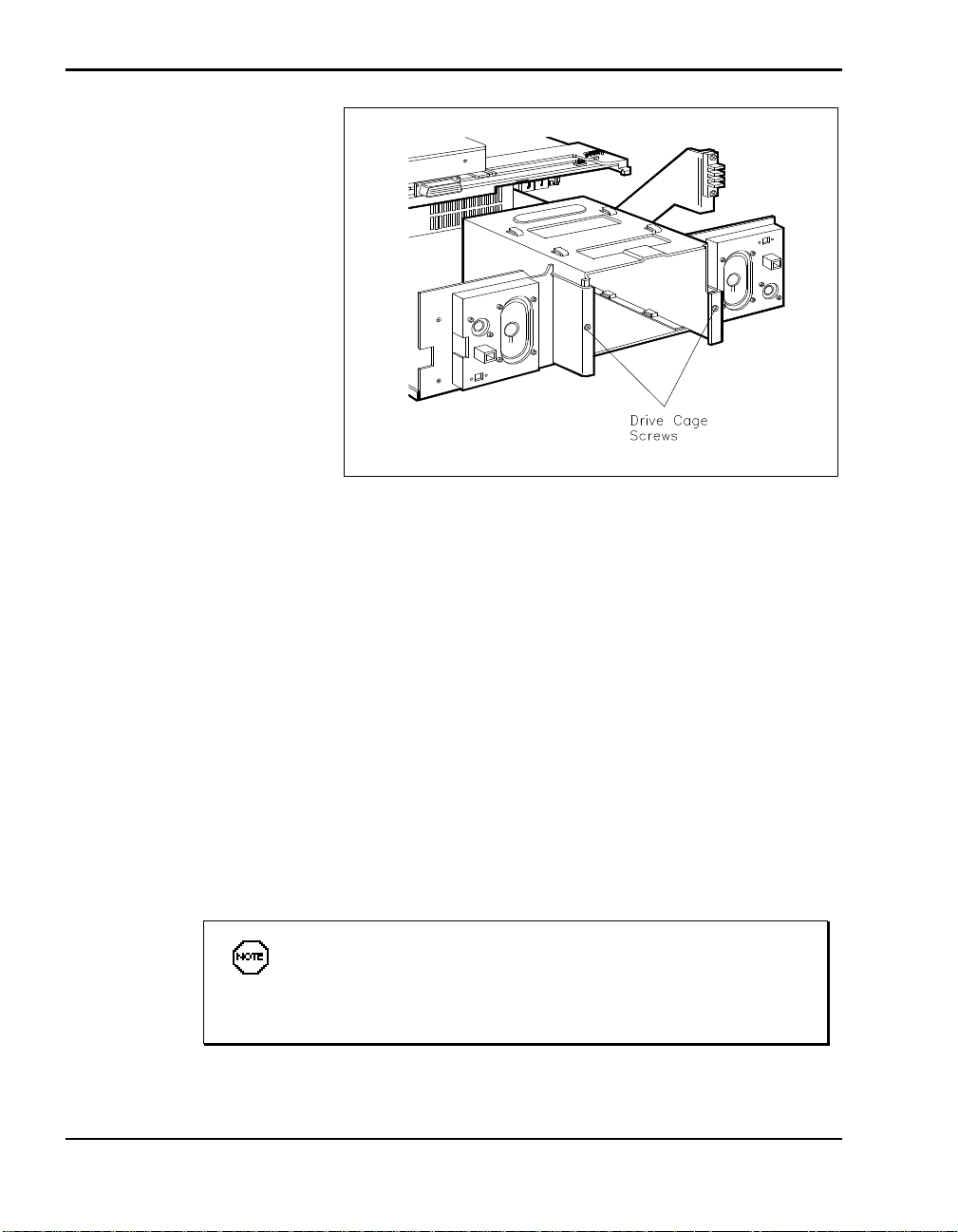
Removing drive cage screws
2. Slide the drive cage towards the back of the unit. Make sure the holes on
the bottom of the cage clear the tabs on the bottom of the docking station
chassis.
3. Lift the drive cage up and out of the docking station.
Securing the NEC VersaBay II Adapter
Next, use the following steps to secure the adapter to the docking station
drive cage.
1. Locate the last row of screw holes on the bottom of the drive cage.
2. Align the bottom set of screw holes on the side of the adapter with the
screw holes on the bottom of the drive cage.
The adapter does not sit on the rails inside the drive cage. Instead, lift the adapter up to line it up with the drive cage screw
holes.
4-46 Adding Options
Page 87
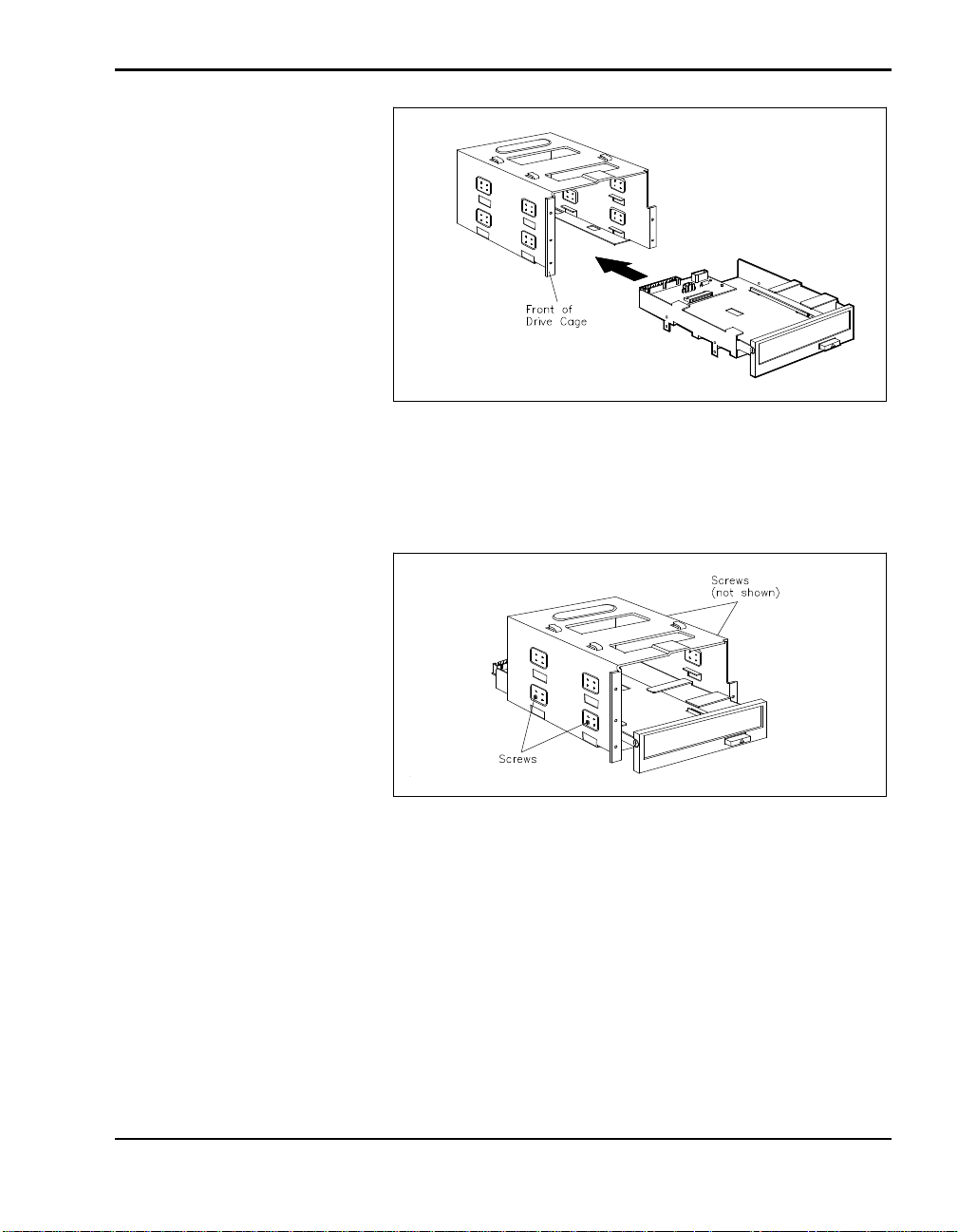
Sliding the adapter into the cage
3. Using the four screws that came with the adapter, secure the adapter to
the drive cage.
Securing the adapter
Adding Options 4-47
Page 88
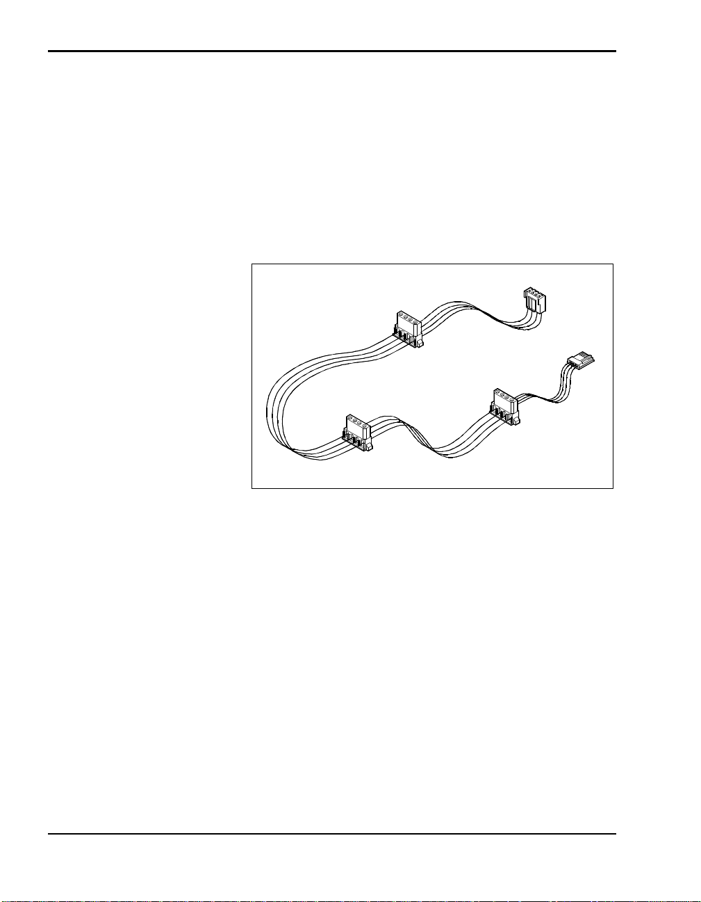
Attaching Cables
Once the adapter is secured to the docking station drive cage, you’ll need to
connect the IDE signal cable, the power cable, and, optionally, the audio cable that ships with the NEC Versa Docking Station 6000.
Attach the cables to the interface board as follows.
1. Look in the package of cables that came with the docking station and lo-
cate the 5-connector power cable.
Locating the power cable
If an optional diskette drive or hard drive is already installed, the power
cable is already attached to these options.
4-48 Adding Options
Page 89
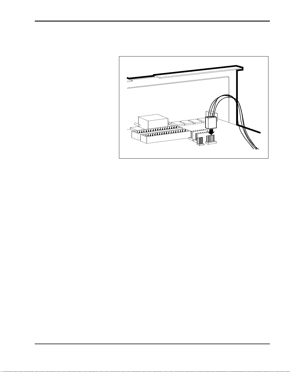
2. Connect the power cable to the docking station interface board, if not al-
ready attached.
Connecting the power cable
3. Locate the IDE signal cable that came with your docking station.
If an optional hard disk drive or CD-ROM drive is already installed, the
IDE signal cable is already attached to the option.
Depending on what other IDE devices are installed in the docking station,
the IDE cable might not be long enough. If not, purchase the appropriate
size cable at a local computer store.
The cable looks similar to the following.
Adding Options 4-49
Page 90
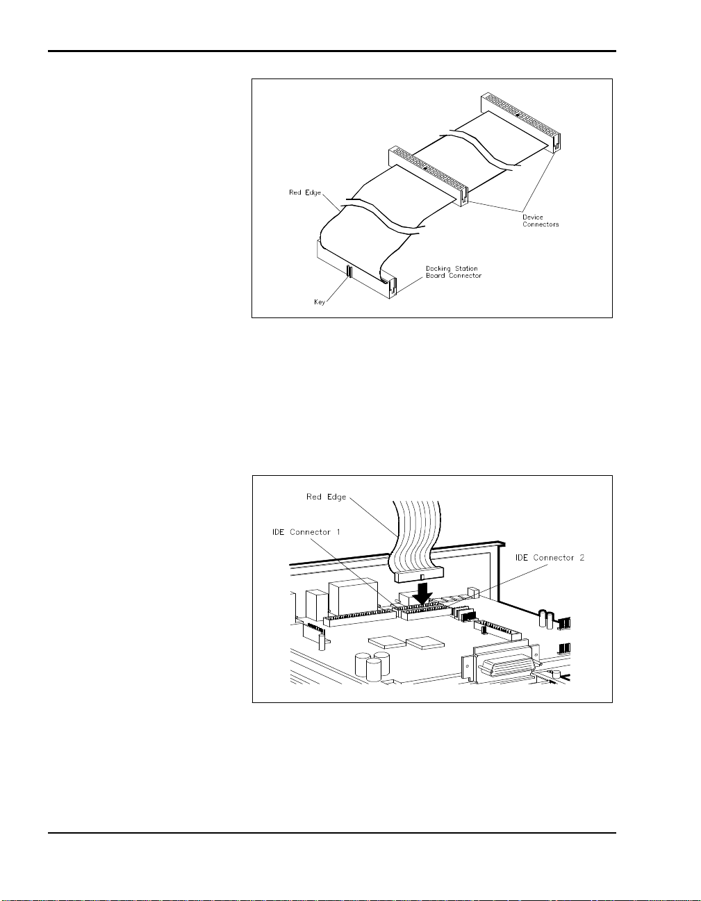
IDE Cable
4. Locate the cable connector to attach to the docking station board. The
connector has a projection that acts as a key on one side.
5. Align the cable connector and the key with the connector on the board
and press firmly to attach them.
Connecting the cable to the docking station board
4-50 Adding Options
Page 91
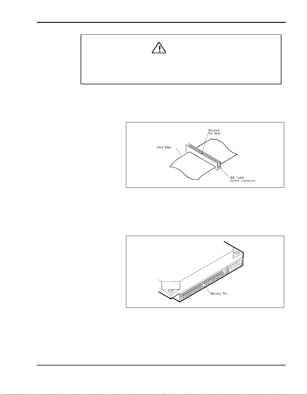
CAUTION
When connecting the IDE cable, be sure to use the correct cable
connector. Using the wrong connector can cause your system to
malfunction and damage the cable.
6. On the IDE cable, pick a connector to attach to your IDE device. Note
the location of the blocked hole in the connector.
Blocked pin hole
7. On the IDE device, locate the gap in the cable port. It looks like a space
with a missing pin.
Missing pin on IDE device connector
8. Align the gap on the device port with the blocked pin hole on the cable
connector and connect them.
Adding Options 4-51
Page 92
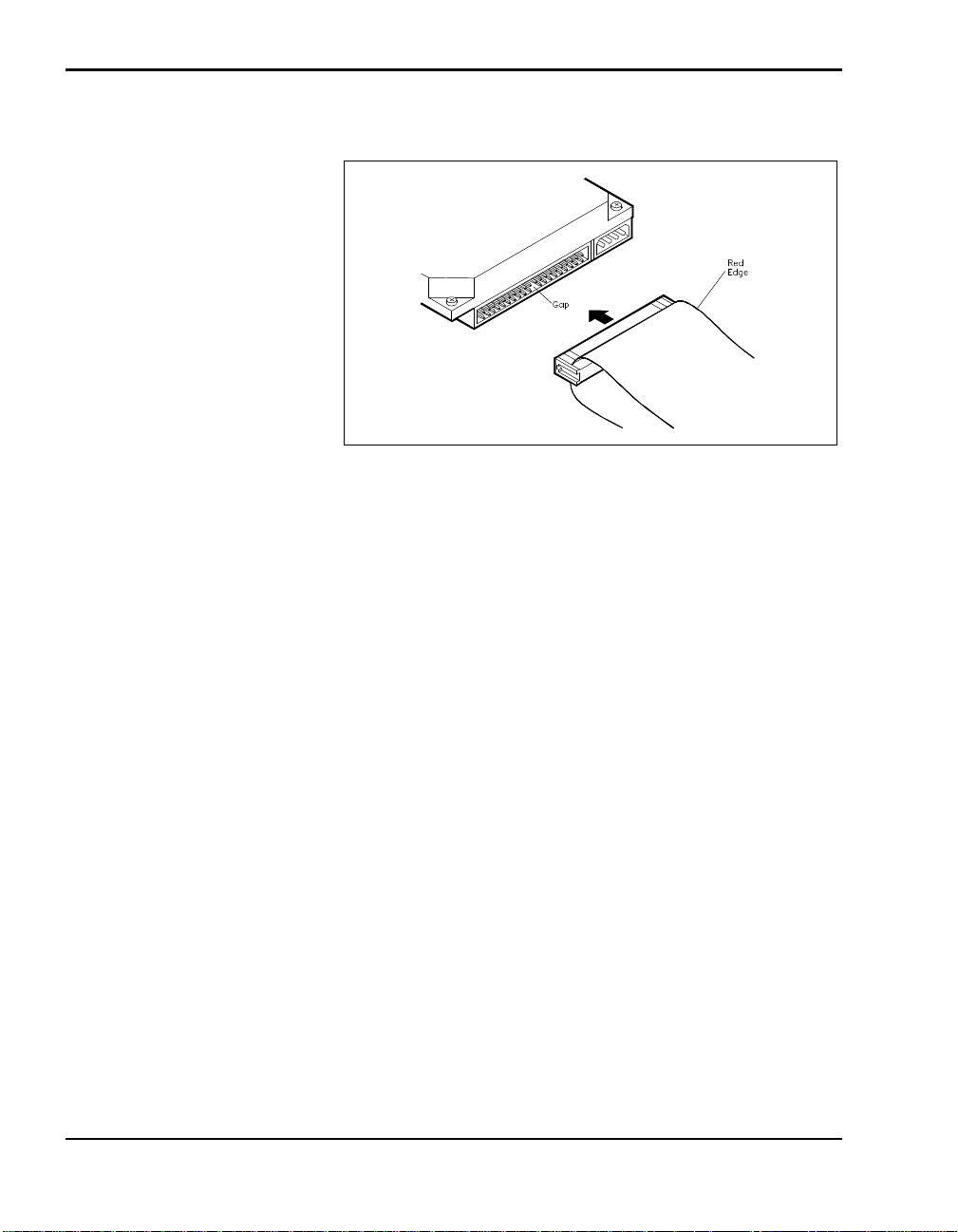
9. Press firmly to secure the attachment.
Connecting the IDE cable to the device
On some IDE drives, the connector is reversed. The gap is in the top row
of pins instead of the bottom row. In this case, turn the cable over so that
the red edge is on the opposite side of the one pictured.
10. If you plan to play audio CDs using your NEC CD-ROM pack, you
will need to connect the audio cable as follows:
n An audio cable is supplied with your NEC Versa Docking Station
6000. Locate the audio cable that came with the docking station.
n If an audio option is already installed, the audio cable is already at-
tached to the option.
4-52 Adding Options
Page 93
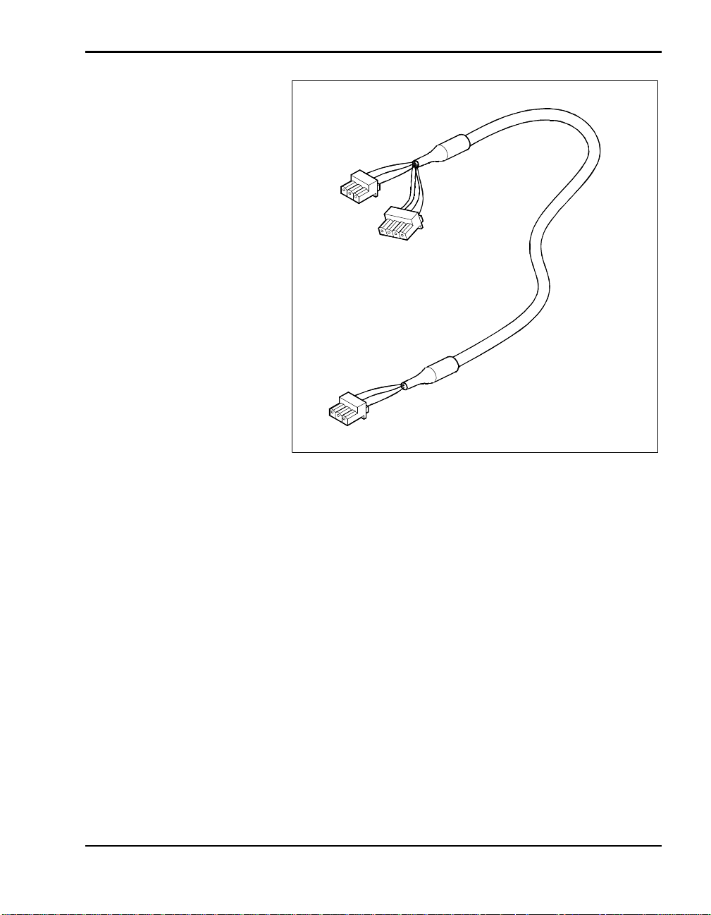
Audio cable
Attach the audio cable to the connector on the docking station in-
terface board.
Adding Options 4-53
Page 94
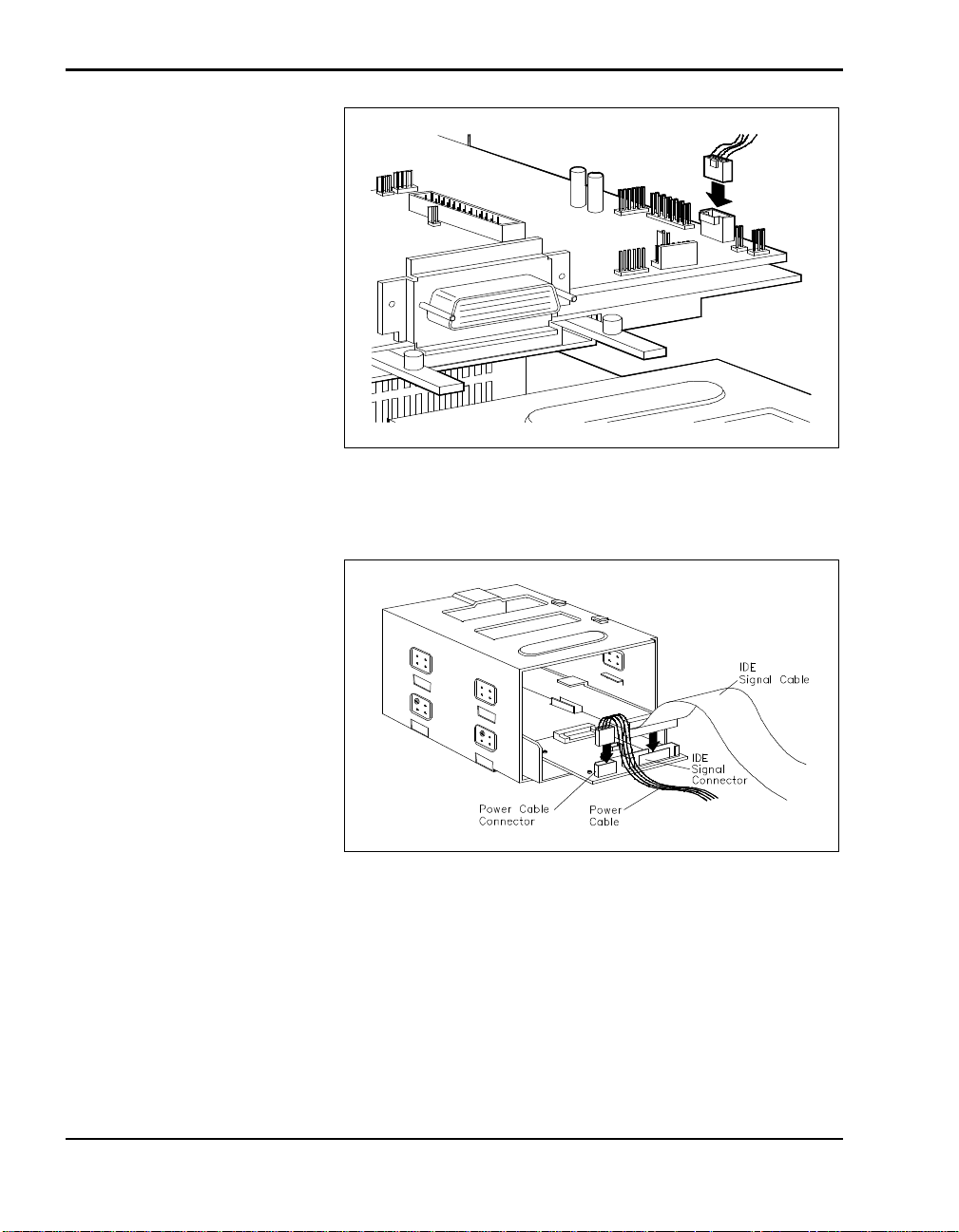
Connecting the audio cable
11. Connect a large power cable connector to connector J4 on the adapter.
Connecting IDE and power cables
12. Connect the smaller, 3-pin audio cable connector to connector J1 on the
adapter.
4-54 Adding Options
Page 95
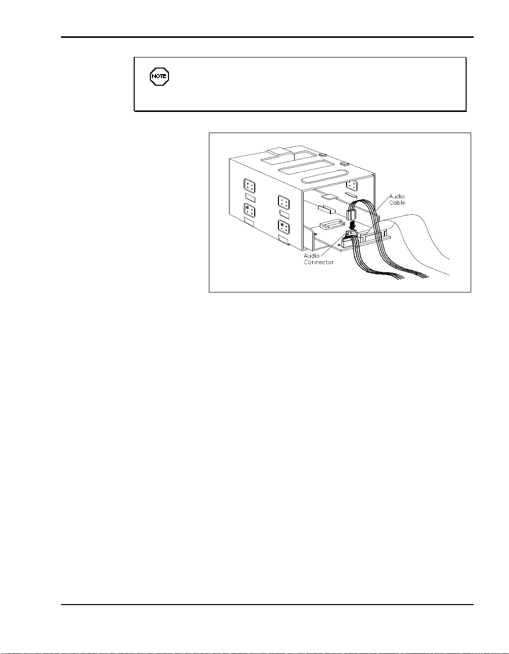
You do not need to connect the audio cable unless you plan to
play audio CDs with the optional NEC CD-ROM pack.
Connecting the audio cable
To finish the installation, go to the next section, “Finishing Up.”
Finishing Up
Finish up drive installation as follows.
1. Locate the tabs on the bottom of the docking station chassis.
2. Position the drive cage a little behind the tabs and lower it into the unit.
3. Slide the drive cage forward until the tabs slide into the matching holes
on the bottom of the drive cage.
4. Replace the two screws that secure the drive cage in the docking station.
Adding Options 4-55
Page 96
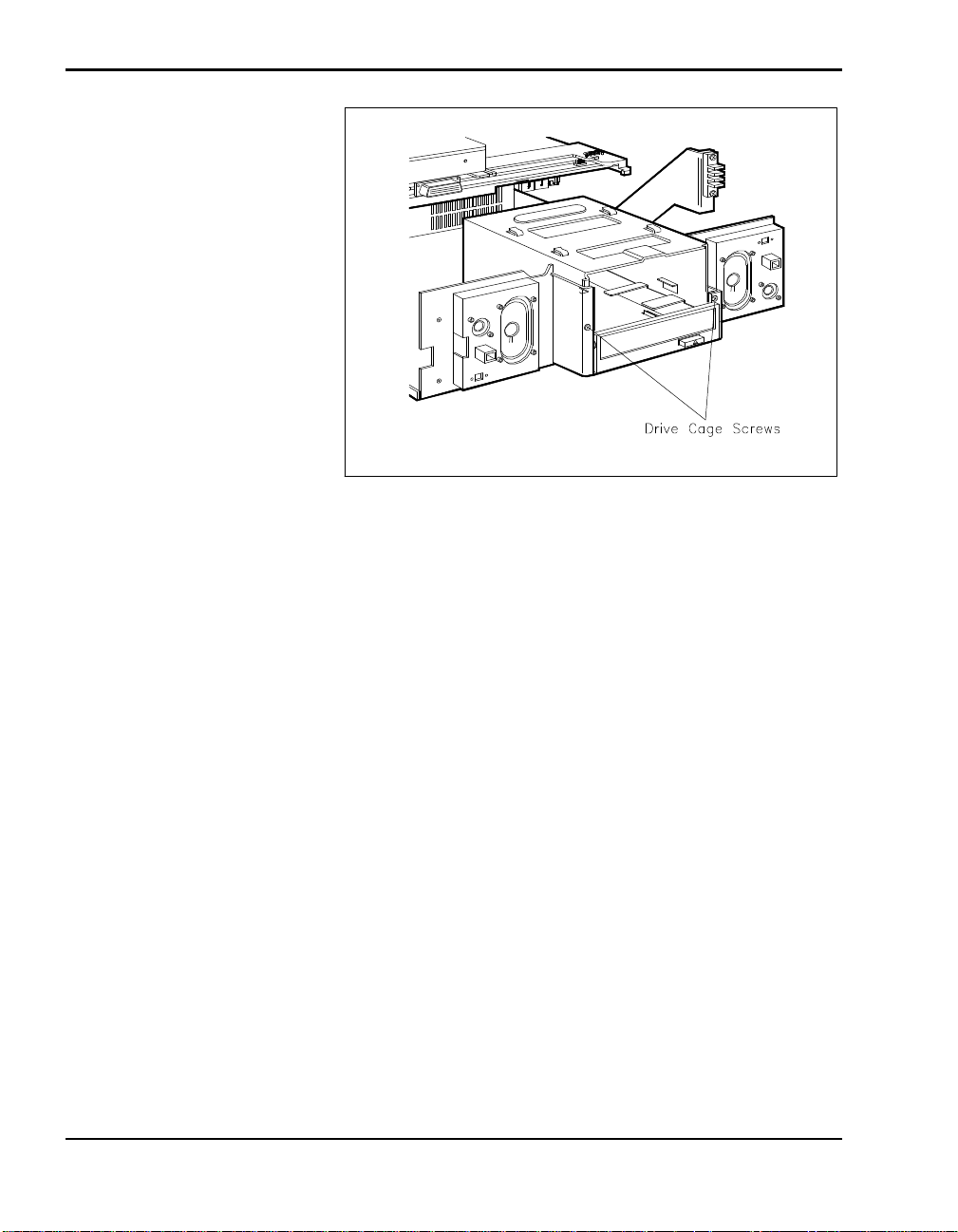
Replacing the Drive Cage Screws
5. If you installed a drive that requires external access, remove the drive
slot cover from the docking station cover as follows:
n Locate the drive slot cover tabs inside the docking station cover.
4-56 Adding Options
n Gently push the tabs out until you can release the cover.
n Remove the slot cover and store it in a safe place for possible future
use.
Page 97
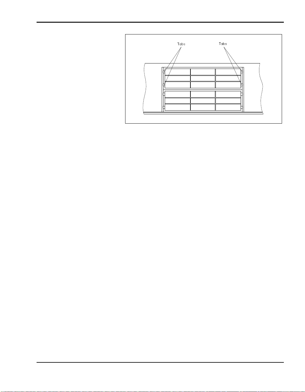
Removing the drive slot cover
6. Being careful to move cables out of the way to prevent crushing them,
replace the docking station cover as described in “Cover Replacement.”
Adding Options 4-57
Page 98

Connecting
5
Peripheral Devices
You can connect peripheral devices, like a printer or an external monitor, to
the NEC Docking Station 6000 for use when the NEC Versa is docked.
Ports for connecting devices are found on the back of the docking station.
Before using peripheral devices, make sure the system parameters match the
system configuration set with your NEC Versa setup utility (also called the
ACU). Parameters and configuration files are discussed in Chapter 3,
Setting Up and Using the Software.
External options that you can connect include the following:
n External monitor
n External keyboard and mouse
n External audio peripherals, including:
Headphone and external speakers
Microphone
External sound sources connected to the Line In or Line Out port
n A standard phone cable to let you use the internal NEC Versa modem.
n Gaming devices, such as a joy stick.
n Parallel devices such as printers
n Serial devices such as an external modem
n External SCSI devices such as a scanner.
Connecting Peripheral Devices 5-1
Page 99
EXTERNAL MONITOR
To connect an external CRT monitor, you need a monitor signal cable. A
signal cable is usually provided with the monitor. One end of the cable must
have a 15-pin connector for the docking station.
You can use an external monitor with or without the CRT base. If you
choose not to use the CRT base provided with the docking station, place the
external monitor on the table or desk next to the docking station.
Always use the CRT base if you are going to put an external CRT
monitor on the docking station. Never place an external monitor or
any other heavy object directly on the docking station or NEC Versa
without the CRT base. Doing so can damage the unit.
The CRT base weight limit is 60 lb (27.2 kg) equivalent to a 17-inch
NEC monitor. Do not exceed the weight limit. Doing so can damage
the unit.
CAUTION
Use the following steps to connect an external monitor to the docking station. If you choose not to use the CRT base, skip steps 2 and 3.
1. Check the following before connecting the CRT.
n Docking station power is off. (Make sure power is off. Otherwise, the
system cannot identify the external monitor type attached.)
n The cover is in place and secured.
n If the NEC Versa is docked, turn off power to the computer. (If you
have a Plug and Play system, you can put your system into Suspend
mode instead of turning off system power.)
n When using the CRT base, the NEC Versa display panel is closed and
secured.
5-2 Connecting Peripheral Devices
Page 100
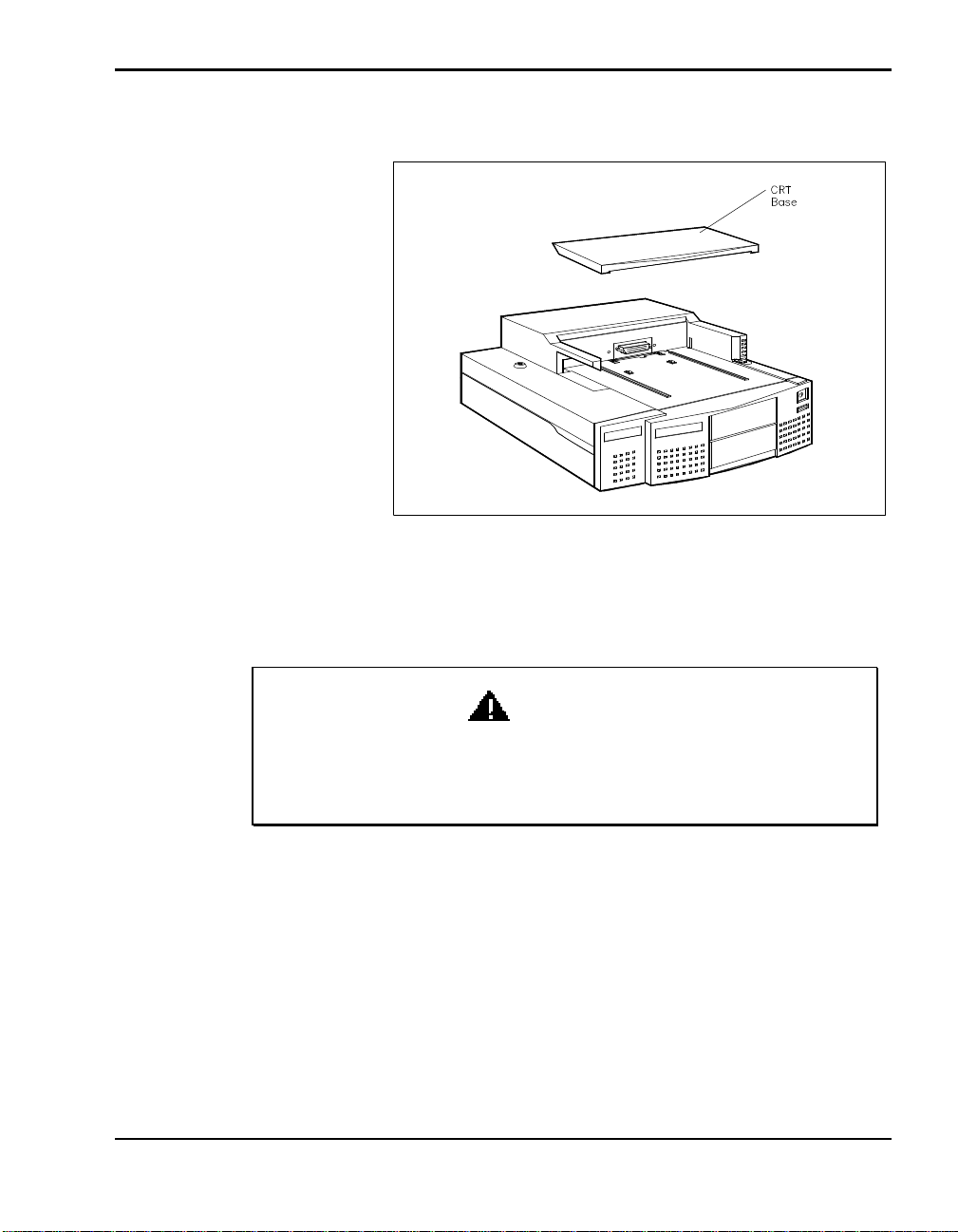
2. Lower the CRT base onto the docking station.
Lowering the CRT base into place
3. Carefully center the external monitor on the CRT base or place it on the
desk.
WARNING
Be sure to center the monitor on the CRT base and docking station
(see the following figure). Putting the monitor too close to the edge
can cause the monitor to fall, causing possible harm or damage.
4. Attach the 15-pin connector on the signal cable to the monitor port on the
docking station.
Connecting Peripheral Devices 5-3
 Loading...