

Page 1
Page 2

Proprietary Notice and Liability Disclaimer
The information disclosed in this document, including all designs and
related materials, is the valuable property of NEC Computer Systems
Division, Packard Bell NEC, Inc. (hereinafter “NEC CSD”) and/or its
lice nsor s. NEC CSD and/or its licens ors , as ap prop ria te, res erve a ll pat ent,
copyright and other proprietary rights to this document, including all
desi g n, manu fa c t ur in g, r eproduc ti o n, u se, a nd s a l es r ight s th ereto, except to
the extent said r i ghts a re expr essly grant e d to oth ers.
The NEC CSD product(s) discussed in this document are warranted in
accordance with the terms of the Warranty Statement accompanying each
product. However, actual performance of each such product is dependent
upon factors such as system configuration, customer data, and operator
contr ol. Since imp lemen ta tio n by custo mers of each p rodu ct may var y, th e
suitability of specific product configurations and applications must be
determined by the customer and is not warranted by NEC CSD.
To allow for design and specification improvements, the information in this
document is subject to change at any time, without notice. Reproduction
of this document or portions thereof without prior written approval of
NEC CSD is pr ohibite d.
NEC and PowerMate are registered trademarks of NEC Corporation, used under license.
All other product, brand, or trade names used in this publication are the trademarks or
registere d t rademarks of th eir respe ct ive trademark ow ners.
First Printing — August 1999
Copyright 1999
NEC Computer Systems Division
6000 Florin-Perkins Road
Sacramento, CA 95828-1037
All Rights Reserved
Page 3

Contents
Using This Guide
Text Conventions.............................................................................xi
Related Documents.........................................................................xii
1 Reviewing System Features
Front Features............................................................................... 1-2
System Controls and Lamps .................................................. 1-3
Diskette Drive A.................................................................... 1-4
Universal Serial Bus Port....................................................... 1-4
CD-ROM Drive..................................................................... 1-5
DVD-ROM Drive.................................................................. 1-5
Tape Backup Unit.................................................................. 1-5
Zip Drive............................................................................... 1-6
PC Card Adapter................................................................... 1-6
LS-120 SuperDisk Drive ....................................................... 1-6
Rear Features................................................................................ 1-7
External Connectors.............................................................. 1-8
Power Supply Features.........................................................1-10
Inside Features.............................................................................1-10
System Board .......................................................................1-11
Network Board.....................................................................1-12
Modem Board......................................................................1-12
Storage Device Support........................................................1-12
Chassis ........................................................................................1-12
Speakers......................................................................................1-13
System Features...........................................................................1-13
Hardware..............................................................................1-13
Software...............................................................................1-14
Preloaded Operating System.........................................1-14
NEC OS Restore CD.....................................................1-15
NEC Application and Driver CD...................................1-15
Security........................................................................1-16
Contents iii
Page 4

2 Setting Up the System
Cable Connections........................................................................ 2-2
Startup.......................................................................................... 2-3
Shutdown...................................................................................... 2-4
Power-Saving Operation............................................................... 2-5
System Care.................................................................................. 2-6
Protecting Your System From Damage.................................. 2-6
Keeping Your System in Good Condition.............................. 2-8
Moving or Shipping Your System.......................................... 2-9
More Information.........................................................................2-10
3 Configuring the System
Configuration Tools and Utilities.................................................. 3-2
BIOS Setup Utility........................................................................ 3-5
How to Start BIOS Setup....................................................... 3-6
How to Use BIOS Setup........................................................ 3-7
Main Menu............................................................................ 3-7
Advanced Menu...................................................................3-11
Security Menu ......................................................................3-18
Exit Menu............................................................................3-19
FLASH Utility.............................................................................3-20
NEC OS Restore CD....................................................................3-21
Introducing OS Restore Options...........................................3-21
Choosing a Restore Program.................................................3-21
Launching the NEC OS Restore CD.....................................3-22
Auto Rebuild and Restore.....................................................3-24
Custom Rebuild and Restore.................................................3-26
Fixing the Operating System.................................................3-29
NEC Application and Driver CD..................................................3-31
Launching the Application and Driver CD ............................3-31
Installing Software...............................................................3-32
NEC Help Center.........................................................................3-33
Installing the NEC Help Center ............................................3-33
Uninstalling the NEC Help Center........................................3-34
Resolutions for NEC VistaScan USB Monitors............................3-34
iv Contents
Page 5

System Board Jumper Settings.....................................................3-35
Processor Jumper Settings....................................................3-37
Clear CMO S/Pass word.........................................................3-38
Power On Mode...................................................................3-40
4 Installing Options
General Rules............................................................................... 4-2
Safety Precautions......................................................................... 4-3
System Unit Covers...................................................................... 4-4
Removing the Left Side Cover............................................... 4-5
Replacing the Left Side Cover............................................... 4-7
Removing the Right Side Cover............................................. 4-9
Replacing the Right Side Cover............................................4-11
System Board Options..................................................................4-12
Memory Upgrade.................................................................4-13
Checking System Memory............................................4-15
Removing a DIMM.......................................................4-16
Installing a DIMM........................................................4-17
Processor Upgrade................................................................4-19
Removing a Celeron or Pentium III Processor...............4-20
Inst alling a Cel eron or Pentium III Upgrade Process or ..4- 22
Removing the Pentium II Processor...............................4-24
Installing the Pentium II Upgrade Processor..................4-26
Expansion Boards........................................................................4-29
Locating Expansion Slots and Connectors ............................4-30
Installing an Expansion Board..............................................4-31
Removing an Expansion Board.............................................4-33
AGP Board..................................................................................4-33
Removing the AGP Graphics Board.....................................4-33
Installing the AGP Graphics Board.......................................4-34
Data Storage Devices...................................................................4-35
Locating Device Bays...........................................................4-35
Preparing the Device ............................................................4-37
Connecting Device Cables....................................................4-37
Diskette Drive Signal Cable..........................................4-40
IDE Signal Cables.........................................................4-41
System Power Cables....................................................4-41
Contents v
Page 6

Cabling Storage Devices.......................................................4-41
IDE Drive Cabling........................................................4-42
Diskette Drive Cabling..................................................4-43
PC Card Adapter Cabling..............................................4-43
Network Board Wake-On LAN Cabling........................4-44
Installing Storage Devices....................................................4-45
Removing the Front Panel.............................................4-45
Replacing the Front Panel.............................................4-48
Installing a 3 1/2-Inch Hard Drive.................................4-48
Installing a 5 1/4-Inch Device........................................4-51
5 Solving System Problems
Solutions to Common Problems.................................................... 5-2
System Problems................................................................... 5-2
Diskette Drive Problems........................................................ 5-4
Monitor Problems.................................................................. 5-5
Keyboard/Mouse Problems.................................................... 5-6
CD-ROM Drive Problems..................................................... 5-7
Speaker Problems .................................................................. 5-8
How to Clean the Mouse ............................................................... 5-9
Battery Replacement....................................................................5-11
How to Get Help..........................................................................5-14
Help From Your Company...................................................5-14
Help From Your NEC CSD Dealer.......................................5-14
Help From NEC CSD Technical Support Center...................5-15
NEC CSD Warranty/Non-Warranty Repair Service..............5-16
6 Getting Services and Support
NEC CSD Website........................................................................ 6-2
NEC CSD FTP Site....................................................................... 6-3
Email/Fax Technical Support Service............................................ 6-3
NEC CSD Bulletin Board System................................................. 6-4
NEC CSD Technical Support Services.......................................... 6-7
vi C ont ent s
Page 7

A Setting Up a Healthy Work Environment
Making Your Computer Work for You..........................................A-2
Arrange Your Equipment.............................................................. A-4
Adjust Your Chair.........................................................................A-5
Adjust Your Input Devices ............................................................A-7
Adjust Your Monitor.....................................................................A-9
Vary Your Workday....................................................................A-11
Pre-existing Conditions and Psychosocial Factors.......................A-12
Checking Your Comfort: How Do You Measure Up?..................A-13
Checking Your Chair...........................................................A-13
Checking Your Keyboard....................................................A-13
Checking Your Mouse.........................................................A-13
Checking Your Monitor.......................................................A-13
Checking You .....................................................................A-14
B System Specifications
System Processor..........................................................................B-2
Processor Support..................................................................B-2
Secondary Cache...................................................................B-3
Processor Socket ...................................................................B-3
Random Access Memory (RAM)..................................................B-3
Cache Memory .............................................................................B-3
Read Only Memory (ROM)..........................................................B-3
Calendar Clock.............................................................................B-4
Input/Output (I/O) Features ...........................................................B-4
Video Memory..............................................................................B-5
Sound System...............................................................................B-6
Fax/Modem Board........................................................................B-6
Peripherals ....................................................................................B-6
Network Board......................................................................B-6
AGP Graphics Board.............................................................B-7
Diskette Drive.......................................................................B-7
Hard Drive............................................................................B-8
Content s vii
Page 8

CD-ROM Drive.....................................................................B-8
DVD-ROM Drive..................................................................B-8
PC Card Adapter...................................................................B-9
Zip Drive...............................................................................B-9
Tape Backup Unit..................................................................B-9
Speakers..............................................................................B-10
Dimensions .................................................................................B-10
System Unit......................................................................... B-10
Keyboard.............................................................................B-10
Power .........................................................................................B-10
Operating Environment...............................................................B-10
Compliance.................................................................................B-11
Index
viii Contents
Page 9

Using This Guide
The PowerMate VT 300 Series User’s Guide provides a
comprehensive reference to infor mat ion about your
computer.
The guide contains the following information:
Chapter 1, Reviewing Syste m Featur es, provides a look at
the front, rear, internal, and peripheral features of the
syste m. It also gives a summary of t he system’s hardware ,
software, and secur it y featur es.
The chapter includes a quick-reference chart for finding
information described more fully later in the document.
Chapter 2, Setting Up the System, explains how to set up,
start up, and shut down the syste m. It also provides
information on insta lling applications, and tips on caring
for the system.
Chapter 3, Configuring the System, describes how to use
the software utilities shipped with your system, including
the BIOS Setup Utility, t he NEC OS Rest ore CD, and the
NEC Applicat ion and Driver CD. It also pro vides
info rmation fo r setting s ys tem bo ard jumpers .
Chapter 4, Installing Options, provides detailed
installation procedures for system upgrades and options.
Chap ter 5, Solving System Proble ms , contains
troubleshooting tips fo r solvin g simple pr oblems a nd
describes how to find help when you cannot solve a
problem yourself.
Using This Guide ix
Page 10

Chapter 6, Getting Services and Support, describes the
services avai lable t o you for info rmation and help, and
describes how to access the services.
Appendix A, Setting Up a Healthy Work Environment,
contains guidelines to help you use your computer
productively and safely. This appendix also instructs you
on how to set up and use your computer to reduce your
risk of developing nerve, muscle, or tendon disorders.
!
WARNING
Prolonged or impr oper use of a c om puter
workstation m ay pose a risk of serious injury. To
reduce your ri sk of i njur y, set up and use your
computer in the manner described in Appendix
A, Setting Up a Healthy Wor k Envir onm ent.
Appendix B, System Specifications, provides a technical
description of your computer and its components.
x Using This Guide
Page 11

Text Conventions
This guide u ses the following text co nventions.
Warnings, caut ions, and notes have the following
meanings:
!
WARNING
Warnings aler t you to situations that could result
in serious personal i njury or loss of life.
!
CAUTION
Cautions indicate situations that can damage the
hardware or software.
:
Note
the material being described.
Notes give important information about
Names of keyboard keys are printed as they appear on the
keyboard, for example,
Text or keystrokes that you enter appear in boldface type.
For example, type
File names are printed in uppercase letters. For example,
Ctrl, Alt
abc123
and press
, or
Enter
Enter
.
.
AUTOEXEC.BAT.
Using This Guide xi
Page 12

Related Documents
In addition to this guide, the following printed documentation
ships with your computer.
NEC PowerMate VT 300i Series Quick Setup/Quick
Reference
The Quick Setup shows how to quickly get the system
connected and powered on.
The Quick Reference briefly describes the documentation,
NEC CSD tools and utilities, so ftware applications, and
services availa ble w ith the NEC PowerMate® VT 300
Series computer.
How Does Your Workplace Measure Up?
This brochure provides information for setting up and
using the computer productively and safely. Informat ion
includes guidelines to reduce the risk of injury associated
with using a computer.
NEC PowerMate VT 300 Series Release Notes
Release Not es pro v ide additional information about the
computer that was not available at the time the user’s
guide was printed.
xii Using This Guide
Page 13

Your system comes with the following online document ation
on the NEC Application and Driver CD.
NEC Help Center
The NEC Help Center is an online guide to Po wer Mate
computers. It provides infor mation about your system
under the following topics: System Tour, System
Information, System Upgrades, Service and Support, and
Reference.
Healthy Environment
This is an online h elp file that complements the “How
Does Your Workplace Measure Up?” broc hur e .
In addition, service and re ference manuals are available on
the Internet at the Service and Support area of the NEC CSD
website (see Chapter 6 for access information).
Using This Guide xiii
Page 14

Reviewi n g System
Features
Front Features
Rear Features
Inside Features
Speakers
System Features
1
Page 15
!
Prolonged or impr oper use of a c om puter
workstation m ay pose a risk of serious injury. To
reduce your ri sk of i njur y, set up and use the
computer in the manner described in Appendix
A, Setting Up a Healthy Wor k Envir onm ent.
This chapter highlights system hardware and software, and
describes the secur it y feat ur es of the system.
Front Features
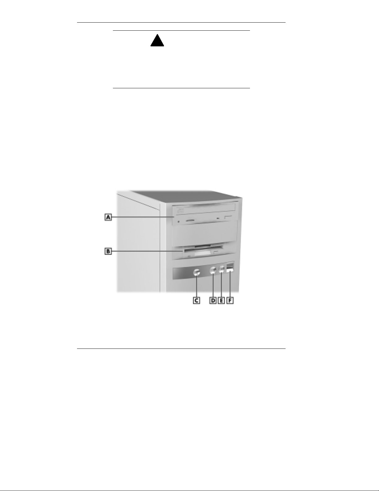
The following figure shows the featur es on the front of the
syste m. A brie f description fo llow s the figure.
WARNING
Front features
A
– CD-ROM Drive
B
– Diskette Drive
C
– Power/Sleep Button
1-2 Reviewing Syst em Featu res
D
– Power/Sleep Lamp
E
– Hard Drive Lamp
F
– USB Port
Page 16

System Controls and Lamps
System contro ls let you se lect specific system operat ions.
Lamps let you know the status of system operation. The
following describes the controls and lamps. The previous
figure shows the co nt ro ls and lamps o n the fro nt of the
system.
Power/Sleep button
Press this button to turn on system power. To turn off
power, press the button and hold in place until the system
powers down (approximately three to four seconds).
Press and immediat ely release t he power/sleep button to
suspend system operation when you plan to be away from
your computer for a short time. Th is place s the system in a
power saving mode. If you have a VESA-compliant
monitor, your monitor also goes into a power-saving
mode.
Press any key or move your mouse to resume system
operation at the point where you stopped it.
An amber system unit power lamp indicates that the
system is in a power-saving mode.
Power/Sleep lamp
The power/sleep lamp indicat es whet her s yst em power is
on or off. It also lets you know if the system is operating
in a power-saving mode.
A steady green lamp indicates that the power is on to all
system components. An amber lamp indicates that the
system is in Sleep mode with full-power reduction.
Reviewing System Features 1-3
Page 17

Har d drive lamp
A lit lamp indicates that t he hard drive is active. The green
lamp tells you tha t the ha rd drive is read ing or writing
data.
Do not turn off the system unless absolutely
necessary whil e the hard drive lamp is lit. To do
so can damage your hard driv e or data.
Diskette Drive A
Use diskett e drive A to copy data files to and from a diskette.
You can also use it as a bootable drive for loading and
starting pro grams fro m a diskette.
To prevent damage to your disket te drive and
data, do not turn off the system or remove a
diskette while the diskette drive busy lamp is lit.
!
CAUTION
!
CAUTION
Universal Serial Bus Port
The universal serial bus (USB) port on the front of the system
allows you to easily and conveniently add plug and play USB
devices without opening up the system. You simply plug the
USB device into the port. You can connect up to 127 devices
including a mouse, monitor, keyboard, printer, scanner,
speakers, and more. A second USB port is on the rear of the
system.
1-4 Reviewing Syst em Featu res
Page 18

CD-ROM Drive
Some models come with a 32X Max or 40X Max variable
speed CD-ROM drive. Use the CD-ROM drive to load and
start progr ams fro m a compact disc (CD). You can also use
the CD-ROM drive to play your audio CDs.
The CD-ROM drive operates at different speeds depending
on whether the CD you are using contains data or music. This
allows you to get your data faster and to see smoother
animation and video.
DVD-ROM Drive
Some models come with a 4X or 6X digital video disc
(DVD)-ROM drive (Windows 98 systems only). The drive
offers many improvement s over the standard CD-ROM
technology, including superior video and audio playback,
faster data access, and greater storage capacities.
The DVD-ROM drive uses DVD technology to read DVD
discs as well as standard audio and video CDs.
Tape Backup Unit
Some models come with a tape backup unit. If your system
has a tape backup unit, you can use it to quickly back up all
or part of your system’s files to a high-capacity tape
cartridge. Backup software helps you tailor the backup
process to protect your files and app lications. Files are
compressed during the backup process to conserve space and
to speed up the process.
Reviewing System Features 1-5
Page 19

Zip Drive
Some models come wit h a Zip® drive. Use the Zip drive to
back up work, archive old files, and transport your work.
Store up to 100 MB of data on a 3 1/2-inch Zip disk.
PC Card Adapter
If your model has a PC card adapter, you can add PC cards to
the system. A PC card is insert ed into a PC card slot similar
to inserting a diskette in a diskett e drive.
Each type of PC card has a different function. With your PC
card adapter, you can add a number of functions to your
system with a variet y of PC cards.
LS-120 SuperDisk Drive
Some models come with an LS-120 MB SuperDisk™ dr ive, in
place of the 3 1/2-inch diskette drive. The drive offers highcapacity, removable data sto r age through use o f SuperDisk
diskettes that hold up to 120 MB of data. The SuperDisk
drive is fully compatible with 1.44 MB disket tes and can read
or write to the diskettes.
1-6 Reviewing Syst em Featu res
Page 20

Rear Features
On the rear of your computer, you’ll find external connectors,
the power supply socket and voltage select switch, and
expansion board slots. The following figure shows the
features.
Rear features
A
– Power Socket
B
– Voltage Selector Switch
C
– Mous e Port
D
– Keyboard Port
E
– USB Port
F
– Serial Port 1
G
– Serial Port 2
H
– Line Out Jack
I
– Line In Jack
J
– Microphone In Jack
K
– Fan
L
– Printer Po rt
M
– MIDI Port
N
– VGA Monitor Connector
O
– Expansion Slots
Reviewing System Features 1-7
Page 21

External Connectors
External connecto r s let you att ach periphera l devices, such as
a monitor, keyboard, mouse, and printer to your system. Your
system has the fo llowing exter na l co nnect ors.
Mouse port
Attach the mouse that comes w ith your computer to this
port. The mouse port supports a PS/2-compatible mouse.
Keyboard port
Attach the keyboard that comes with your computer to the
ke yboard port.
The keyboard port supports a PS/2®-compatible (personal
system/2-compatible) 101-key or 104-key keyboard (in the
U.S. and Canada) or a 102-key keyboard (in the United
Kingdom and Germany) with a 6-pin mini DIN connector.
VGA monitor connector
The system comes with an acce lerated graphics port
(AGP) graphics board. The external video graphics array
(VGA) connector on the AGP board supports an NEC
MultiSync® monitor , NEC VistaScan™ monitor, or other
VGA-compatible monitor with a 15-pin connector. Att ach
the signal cable from your monitor to the VGA connector.
Printer port
Use this port to connect a parallel printer with a 25-pin
connector to the system.
Serial ports 1 and 2 (COM1 and COM2)
Attach a serial device with a 9-pin connector to these
serial ports. Serial devices include a pointing device, serial
printer, or a modem.
Unive rsal Se rial Bus port
This port adds a USB connector at the rear of the system
(see “Universal Serial Bus Port” earlier in this chapter) .
1-8 Reviewing Syst em Featu res
Page 22

Audio connectors
The following connector s co me integrat ed o n t he syste m
board (see the preceding figure for jack locations).
Microphone in jack
The microphone in jack lets you connect a microphone
for recording audio information in your data s ystem
files.
Line in jac k
The line in jack lets you connect a stereo audio device
suc h a s a stereo amp lifier or a ca s s e tte o r minidisc
player for playback or recording.
Line out jack
The line out jack allows you to connect an amplified
output device, such as powered speakers or headset, a
stereo tape recorder, or an external amplifier for audio
output.
MIDI/Joyst ick co nnect or
The MIDI/Joystick connector lets you attach a joystick to
your system for use with games.
Fax/modem ports
Some models come with a V.90 rated 56-kilobytes per
second (Kbps) fax/mo dem board. The fax/mo dem boa rd
allows the connection of a phone line to the computer for
fax and data communications functions.
Dual fax/modem ports let you use a telephone line for the
fax/modem and your telephone.
LAN connector
Some models come with a networ k board. Use the RJ-45
compatible port on the board for connect ing the system to
an Ethernet local-area net work (LAN).
Reviewing System Features 1-9
Page 23

Power Supply Features
Your system has the following power supply features:
Power socket
Connect your power cable to t his socket .
Voltage selector switch
Sets the voltage for your system to 115 volts or 220 volts.
!
Set the switch cor r ectly for the voltage in your
area. Most wall outlets in the United States and
Canada are 115 volts. O utlets in Europe,
Australi a, and Asi a ( ex c ept T aiwan) are
230 volts. Tai wan uses 115-volt outlets.
Pow e r supply fa n
The power supply fan cools the power supply and other
system component s to keep t hem from overheating. Keep
the area near the fan clear for proper vent ilat ion.
CAUTION
Inside Features
See the following figure for the location of features w ithin the
system. Feature descriptions follow.
1-10 Reviewing System Features
Page 24
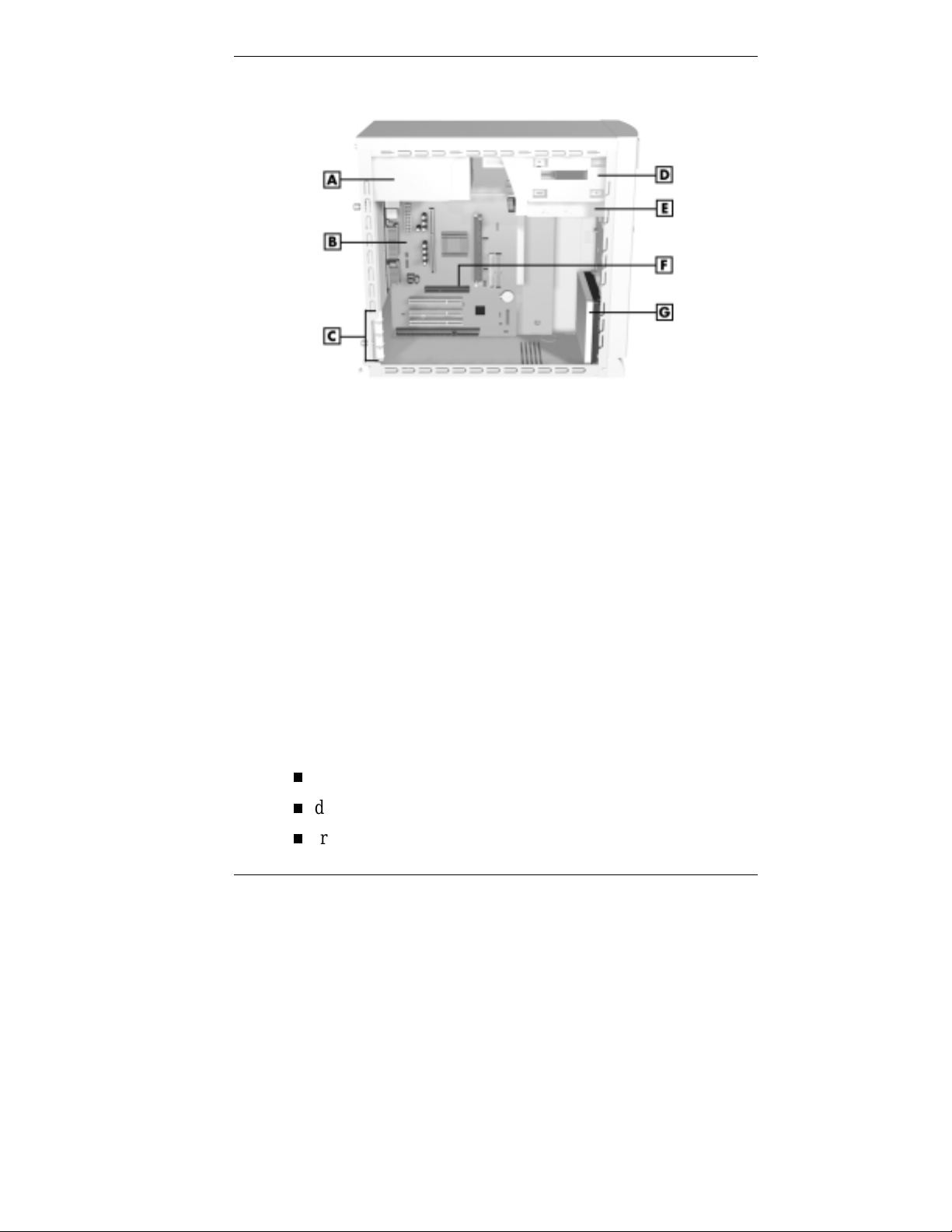
Inside the system
A
– Power Supply
B
– System Board
C
– Expansion Slots
D
– Accessible Device Bays
System Board
The syste m processor, memory, audio subsystem, s yst em
battery, internal connecto r s, and externa l connectors are on
the system board. For information on the external connector s,
see “External Connecto rs” earlier in this chapter.
The system board supports a diskette drive and up to four
IDE devices such as IDE hard drives, IDE CD-ROM drive,
IDE DVD-ROM drive, and IDE Zip drive.
Internal connecto r s on the system board include:
primary and secondary IDE co nnectors
diskette drive connect or
front panel connectors for lamp, USB, and audio signals
E
– Diskette Drive
F
– AGP Board Connector
G
– Hard Drive
Reviewing System Features 1-11
Page 25

power connector s
AGP graphics board connector
three PCI connecto r s
one ISA connector
additional connectors include the CD Audio In, Modem
In, Wake-On LAN, and fan.
Network Board
Some models come wit h a 3 Co m® 10/100Base-T Ethernet
net work boar d, an Intel® EtherE xpress® Pro100 +10/100
Ethernet network board, or a GVC D110G 10/100 network
board installe d in a PC I slot .
Modem Board
Some models come wit h a Robotics® 56K Python V.90 ISA
modem board or a Lucent V.90 Winmodem PCI board.
Connect your telephone line to th is board.
Storage Device Support
Five storage device bays accommodat e up to three accessib le
devices and two internal hard drives.
Chassis
The NEC micro tower chassis conforms to the Intel ATX
form factor specificat ion. The c hass is features the following:
standardized chassis s ize and d imensions
standardized system board size and dimensions
standardized ATX 145 watt power supply.
1-12 Reviewing System Features
Page 26

Speakers
If ordered, some systems come with two high-quality stereo
speakers. One of the speakers connects to the line out jack at
the rear of the system unit.
An AC adapter comes with the speakers. I n stall the AC
adapter along with the speakers.
Adjust the speaker volume by using the vo lume cont ro l on
the front of the syste m or on the right speaker . Yo u can also
use the Windows sound software. To bring up the Windows
volume control, double click the speaker icon on the t askbar
(next to the syste m clock). Use the software to balance the
sound between the left and right speaker s.
System Features
Your computer hardware and software deliver the
performance and technologies you need for all your
challenging tasks today and into the future.
Hardware
The PowerMate VT 300 Series includes the following
hardware features:
PC98 Compliance
All the hardware in the system has been certified by
Microsoft® to be PC98 compliant.
Processor
The system comes with a Celeron® processor, Pentium® II
processor, or Pentium III processor. Processor speed
depends o n s yst em model. The processors are fast,
power ful pro cessors that lend t he mse lves to
computational, graphical, and networking tasks.
Reviewing System Features 1-13
Page 27

Audio on the System Board
The system board comes w ith an audio subs yst em. The
audio chipset gives you a surrou nd sound system for threedimensio nal sou nd effe c ts — much like a live
per formance. It also provides wavetable synthesis.
(Wavetable synthes is uses actual recordings of real sound
effects and musical instr uments for a dynamic audio
experience.)
Flashable ROM BIOS
The system’s ROM BIOS features system setu p
configuration, Plug and Play support, and flash support for
easy and economical BIOS upgrades.
System Memory
Your computer comes with at least 32 MB o f non-ECC
synchronous dynamic random access memory (SDRAM)
and supports up to 512 MB.
AGP Graphics Board
All models ship with an AGP gr aphics board. AGP
enhances graphics performance, particularly for 3-D
applications.
Po wer Manageme nt Options
Power management opt ions conserve energy and reduce
power costs.
Software
NEC CSD provides a variety o f applicat ions and hardware
utilities with your system to let you take advantage of your
hardware capabilities.
Preloaded Operating System
The Microsoft® Windows NT®, Windows® 95, or Windows
98 operating system comes loaded o n your syst em.
1-14 Reviewing System Features
Page 28

NEC OS Restore CD
In the event of operat ing system problems, you can rest ore
your operating system using the NEC OS Restore CD. The
NEC OS Restore Program on the CD provides a “Fix OS”
Restore option for reinstalling the Windows 95 or
Windows 98 operating system while leaving data files intact.
This feature lets you back up your data files before
performing a complete restore of the operating system.
The OS Restore program also provides options for
reformatting and repartitioning the hard drive. In addition, the
program automatically deter mines which dr ivers are needed
for your original hardware configuration and insta lls them
during the restore.
NEC Application and Driver CD
Your system comes with an NEC Application and Driver CD.
Use this CD to install any or all of the software that comes
with your system, including:
Microsoft® Internet Explorer
Internet Exp lorer prov ides a t op-no tch browse r with
preloaded links for easy access to t he world wide web.
Also use Internet E xplorer to access one of the many new
browser-based utilities.
Netscape® Browser
Netscape provides a top-notch browser with preloaded
links for easy access to the wor ld wide web. Also use
Netscape to access o ne of the many new browser - based
utilities.
Reviewing System Features 1-15
Page 29

Adobe® Acrobat® Reader
Use the Adobe Acrobat Reader to read and print portable
document format (PDF) files found on the Internet and
PDF documents included with various software
applications.
Network™ Assoc iat es VirusScan® Software
Protect the system from viru ses by running VirusScan.
PartitionMagic™
Repartition your hard drive while leaving your data intact
with PartitionMagic. Includes BootMagic™ software for
eas il y mana g in g multip le op er a t ing systems.
NEC Help Center
The NEC Help Center is an online guide with information
about the Power Mate system.
Healthy Environment
This is an online version of the printed brochure, Setting
up a Healthy Environment.
The NEC Applicat ion and Driver CD also contains a wide
selection of dr ivers for hardwar e that is compatible with
PowerMate series co mputers. These drivers are provided with
the original manufacturer’s inst allation wizard s t o ensure
correct inst allation.
Security
The system has hardware, software, and mechanical securit y
features that offer protection against unauthorized access to
your system and data. The following security featur es ar e
available with the syst em.
Passwor d security
The BIOS Setup utility includes a feature t hat lets you set
up either a user or supervisor password, or both.
1-16 Reviewing System Features
Page 30

The user password controls booting of the system and
controls access to the Setup utility and the keyboard. (User
access to the BIOS Setup utility is limited to a subset o f all
BIOS Setup parameters when a supervisor password has
been set .)
The supervisor password allows full access to t he system
and the BIOS.
Windows network secur it y features
To learn more about the network security features
available through the Windows operating system, refer to
your Windows documentation or consult your system
administrator.
Locking tab
The system also has a lock ing tab o n the rear of the
chassis. The tab fits through a slot on t he rear edge of the
chassis cover when the co ver is on. When a pad lock is
used in the tab, the system is physically prot ected from
chassis intrusion.
Reviewing System Features 1-17
Page 31

2
Setting Up the System
Cable Connections
Startup
Shutdown
Power-Saving Operation
System Care
More Information
Page 32

This chapter provides the informat ion you need to set up and
use your system. This includes ca ble co nnections, system
startup procedures, system shutdown procedures, and system
care. The chapter also includes a matrix showing where to
find additional information about the computer.
Cable Connections
After unpacking the system and positioning the system unit in
your work area, connect the syste m co mponents using your
Quick Setup poster and the following tips.
Use the icons on the rear o f the system unit to identify the
keyboard, mouse, printer, USB, and monitor connectors.
If the system comes with a fax/ mode m board, connect it to
the telephone line as follows:
Unplug the telephone from the telephone jack on the
wall.
Plug the telephone cable that co mes w ith the syst em
into the line jack on the rear of the syste m and into the
telephone jack on the wall.
Plug the cable on the telephone into the phone jack on
the rear of the system.
If your system comes with the network board option, see
your network administrator for guidelines on configuring
the system for network access.
2-2 Se tting Up the System
Page 33

Set the voltage switch correctly for your area. The correct
setting for the U.S. and Canada is 115V.
Set the voltage switch cor r ec tly for your area.
Connect syste m power cables to a surge protector
(recommended) or a properly grounded wall outlet.
NEC CSD recommends connecting the power
cable to a surge protect or .
Startup
Press the power button to start up yo ur syste m. The power
lamp lights green to indicat e that the system is on. The
system performs its Power-On Self-Test (POS T) and several
messages appear indicating that your system is checking its
subsystems. To see t he messages, pr ess
!
WARNING
!
CAUTION
Tab
during POST.
At the bottom of the NEC startup scr een, the following
message appear s:
If you want to enter t he BIOS Setup, immediately press
while the startup scr een d isplays.
One beep indicates that the system has successful ly
completed the power-on test. After a short delay, Windows
starts up.
Press F2 to enter BIOS Setup
F2
Setting Up the System 2-3
Page 34

If a problem occurs, a series of beeps may sound. I f this
happens repeatedly after powering on, power off the system
and turn to Chapter 5, “Solving System Problems.” The
chapter provides helpful hints for solving system problems.
Note
indicating that system settings have changed,
run the BIOS Setup utility (see Chapter 3,
“Configuring the System”).
On systems loaded with the Windows NT® 4.0 operating
syste m, pr ess
The log-on box appears for enter ing a password.
Shutdown
Follow these steps to power o ff your computer .
1.
Save your work and exit all open application programs.
2.
Make sure that the hard drive, diskett e dr ive, and any
other drives are not in use. A lit device lamp indicates t hat
the device is in use.
If the system display s a message
:
Ctrl Alt Del
when prompted on-screen to do so.
!
Wait until a progr am i s finished running before
powering off the system.
Unless absolutel y nec essary, never power off the
system when the system power l am p is amber or
when either the hard drive lamp, diskette drive,
or other device lamp is li t. Inf ormation on the
device might be l ost or damaged.
2-4 Se tting Up the System
CAUTION
Page 35

3. Click
Shut Down
on the taskbar, then point to and click
Start
. Selecting
Shut Down
gives you several
choices in the pop-up submenu. Select
computer
, then click
Yes
or press
Enter
4. If your system is configured with Windows 98, the
system shuts down automatically after a short interval.
Note
pressing the power button and holding it in for
several seconds bef or e r eleasing. The system
powers off after a short del ay .
You can also power off the system by
:
5. If your system is configured with Windows 95 or
Windows NT, shut down the system by pressing and
ho lding in the power button for sever al seconds be fore
releasing.
6. Turn off power to your monitor.
Power-Saving Operation
Shut down the
for shut down.
If the system is running Windows 95 or Windows 98, you can
put it in Sleep mode (a power-saving state) by lightly
pressing and immediately releasing the power button on the
front of your unit. The Sleep mode is a convenient way of
conserving energy when you are going to be away from your
system for a short period of time.
The system also goes into Sleep mode when it has been
inactive, if the powe r manageme nt has been en abled in BIOS ,
and an inactivity timeout has been enabled. (See Chapter 3,
“Configuring Your System” for information on se tting po wer
manag e me nt functions . )
Setting Up the System 2-5
Page 36

Take care to lightly press and immediately
release the power button t o enter the Sleep
mode. Avoid pressing and hol ding in the power
button or you may tur n off power and lose data.
When the system goes into S leep mode, it saves data and
system status and then shuts off power to all possible
components. Sleep mode lets you save power without first
saving your wo rk.
An amber power lamp indicates t hat t he syste m is in Sleep
mode. Press a key or move the mouse to r esume s yste m
operation where you left off.
System Care
Your system is a durable, dependable computer built for
heavy use. With protective measures and pro per care, you can
prevent problems and promote the successfu l operation and
long life span of your computer.
!
CAUTION
Protecting Your System From Damage
There are several ways that you can prot ect your syst em from
po ssible damage. NEC C SD strongly rec omme nds t he
following protective measures.
Connect a surge suppressor between your computer and a
grounded wall outlet. A surge suppressor protects your
system from sudden transient increases and decreases in
electrical power.
2-6 Se tting Up the System
Page 37

Be sure to connect all peripherals, such as your monitor
and printer, to the surge suppressor. The surge protector
should be the only device that you plug into the wall
outlet.
Avoid repeated power-o n c ycles. These su bject the system
components to temperature variations and stress.
Disconnect yo ur system from telephone and power lines
when an electrical sto r m threat ens. I f you have a
fax/modem, lightning can travel in on the phone line and
damage both the fax/modem and the system unit.
Lightning can also travel in on power lines and damage
your monitor and system unit.
Be sure that system power is off before you connect or
disconnect a cable. Never make cable changes when the
system power is on. Doing so can damage the system and
its peripher als.
Use BIOS Setup utilit y options to protect against viruses
(see “Security Menu” in Chapter 3). Use appro pr iate virus
detection software regularly to protect your system from
computer viruses.
If you plan to use software programs other than NEC CSD
supplied software, NEC C SD stro ngly recommends that
you take the necessary st eps, such as virus checks, to
protect your system.
Position your computer away fro m direct sunlight and
extreme hot and cold temperatures.
The recommended operating environment is from 50°F to
95°F (10°C t o 3 5°C).
The recommended non-operating environment (shipping
or storage) is from 14°F to 158°F (-10°C to 70°C).
Setting Up the System 2-7
Page 38

After turning off power, wait about five seconds for the
hard drive to spin down before you power on again.
Be sure that nothing is p laced on top of your system power
cables.
Prevent dust from entering your system by covering it
when it is not in u s e .
Keeping Your System in Good Condition
Maintain the condition of your system by periodically using
the following procedures.
!
WARNING
For safety, power off and unplug your system,
monitor, and any exter nal devices before
cleaning them.
Clean the outside of the computer with a soft clean cloth.
Yo u can re move stubborn stains with a cloth slightly
dampened with a mild detergent . Never use a st rong
cleaner or solvent on any part of the system.
Keep food and liquids away fr o m your computer.
Periodically clean the keyboard with a vacuum cleaner
brush attachment. Do not use any liquid cleaners on the
keyboard as they can damage the keyboard.
If an object, such as a paper clip, falls into the keyboard,
turn the keyboard over and gently shake it.
Clean the monitor screen wit h a g lass cleaner and wipe it
with a clean, lint-free cloth. You may use wet/dry cleaning
pads manufactured for monitor screens.
2-8 Se tting Up the System
Page 39

Moving or Shipping Your System
Use these steps to pr epar e your syst em for moving or
shipping.
1. Back up the files on the hard drive to diskettes, Zip disks,
tape cartridges, or other backup devices.
Take precautions for storing and transpo rting Zip disks,
diskettes, o r tape cartr idges so t hat t hey are not exposed
to magnetic fields or electrical impulses.
2. Remove any diskette from the diskette drive. If you have
a CD in the CD-ROM drive, remove the CD.
3. Turn off the system unit and any external options
connected to it.
4. Unplug the system unit power cable from the wall outlet
or surge suppressor, then from the unit itself.
5. Unplug any external options fro m the wall outlets or
surge suppressor, then disconnect t hem fro m the system
unit.
6. Pack the system components in the original shipping
materials and carto ns. If these are not available, be sure to
use adequate packing materials to prot ect the components.
To set up your system, follow the st ep s on the
PowerMate VT 300i Series Quick Setup poster that comes
with the computer.
Setting Up the System 2-9
Page 40

More Information
Once you have your system up and running, we suggest that
you do the following:
Install applications provided by NEC CSD on the NEC
Application and Driver CD.
See “Setting Up a Healthy Work Environment” in
Appendix A.
Install any of your own applicat ions. S ee the
documentation that comes w ith the app licat ion.
See the following quick reference chart to find informat ion
about using the computer.
Quick Reference to Information About the Computer
Information Where to Find It
Installing the applications pr ovided by
NEC CSD
Installing the NEC Help Center online
documentation
Uninstalli n g th e NEC Help Center “Uninstallin g th e NEC Help Center” in
Setting a password Chapter 3
Adding options Chapter 4
Accessing the world wide web Chapter 6
Protecting the syst em from viruses Chapter 1
Using support services Chapter 6
Taking care of the system “System Care” in Chapter 2
Troubleshooting tips Chapter 5
“In stalling Applications” in Chapter 3
“Installi ng the NEC Help Center” in
Chapter 3
Chapter 3
2-10 Se tting Up the System
Page 41

3
Configuring the System
Configuration Tools and Utiliti es
BIOS Setup U tility
Flash Utility
NEC OS Restore CD
NEC Application and Driver CD
NEC Help Center
Resolutions for NE C VistaScan USB
Monitors
System Board Jumper Settings
Page 42

This chapter provides information on configuring your
computer. The chapter includes infor mation on the
American M e gatrends , Inc. (AMI) B IOS S etup ut ility fo r
configuring hardware and the system
Flash utility for BIOS updates
NEC OS Restore CD for rebuilding the hard drive and/or
restoring the operating system
NEC Applic ations and Driver CD for installing the NEC
supplied applications and optional drivers
jumper settings for physically configuring devices in the
system.
See the followin g tab le for a quick guide to the utilities, t ools,
or procedures required in configuring the system. For detailed
information abo ut t hese and other tools, see the sections
following the t able.
Configuration Tools and Utilities
The following table lists ways you can configure t he system,
and the utility, tool, or procedure to use for the configuration.
3-2 Configuring the System
Page 43

Configuration Tools and Utilitie s
Configuration Method, Tool, or Utility
BIOS, updating FLASH utility
Boot devices, deter mining BIOS Setup (Advanced menu )
Boot order, changing BIOS Setup (Advanced menu)
Clearing CMOS and password Jumper Settings
Configuring processor jumpers on system
board
DIMM memory, checking BIOS Setup (Main menu)
Diskette drive, enabli ng BIOS Setup (Mai n m enu)
Drivers for NEC CSD hardware, installing NEC Application and Driver CD
Hard drive, reformatting NEC OS Restore CD
Hard drive, repartioning NEC OS Restore CD
Har d driv e, setting a pre-delay BIOS Setu p (Adva nced menu)
Hard drive, subjecting to power m anagement BIOS Setup (Advanced menu)
Healthy Environment (online document),
installing
Inactivity timeout, setting BIOS Setup (Advanced menu)
Keyboard options BIOS Setup (Advanced menu)
Mem ory, c hecking BIOS Setu p (Main menu)
NEC Help Center, installing NEC Application and Driver CD
NEC Help Center, uninstalling see “Uninstalling the NEC Help
Jumper Settings
NEC Application and Driver CD
(see “Ins talling the NEC Help
Center”)
Center”
Operating system, restoring NEC OS Restore CD
Configuring the System 3-3
Page 44

Configuration Tools and Utilitie s
Configuration Method, Tool, or Utility
Parallel port, enabling, configuring BIOS Setup (Advanced menu)
Pas sword, setting or clearing (user,
supervisor, or both)
Plug and Play, enabling BIOS Setup (Advanced menu)
Power management, enabling, configuring BIOS Setup (Advanced menu)
Processor speed, changing Jumpers
Serial ports, enabling BIOS Setup (Advanced menu)
Software provided through NEC, installing NEC Application and Driver CD
Sound, enabling BIOS Setup (Advanced menu)
Time and date, setting BIOS Setup (Main menu)
USB functions BIOS Setup (Advanced menu)
Video device, subjecting to power
management
Windows 95, Windows 98, or Windows NT,
restoring
BIOS Setup (Security menu)
Jumper Settings
BIOS Setup (Advanced menu)
NEC OS Restore CD
3-4 Configuring the System
Page 45

BIOS Setup Utility
The AMI BIOS Setup utility program is used to configure the
main components of yo ur computer.
Your system ships from the factory with the corr ect system
parameters for your configuration. Unless you add optional
hard ware, you do not need to run the BIOS Setup utility t o
operate your system. However, you might wish to run the
Setup utility to set featur es t hat customize your system, such
as security featur es.
System configurat ion information is stored in nonvolatile
memory. A nonvolat ile memo ry device re tains its da ta when
system power is turne d off. Nonvolat ile memo ry in yo u r
system is stor e d in a co mpleme ntary meta l-oxide
semiconductor (CMOS) memory ch ip backed up by a batt ery
on the system board. The battery supplies continuous power
to CM O S memory and ma intain s configura tion informatio n
when system power is off (see “Battery Replacement” in
Chapter 5).
NEC CSD recommends that you print out or write down your
current BIOS Setup parameters and store t he informatio n in a
safe place. This lets you restore your system to the current
parameters if you ever need to replace the battery.
Configuring the System 3-5
Page 46

How to Start BIOS Setup
Main Menu
Main Advanced Security Exit
BIOS Version
Processor Type
Processor Speed
Cache RAM
Total Memory
DRAM Bank 0
DRAM Bank 1
System Date
System Time
Floppy Drive A
Floppy Drive B
Primary IDE Master
Primary IDE Slave
Secondary IDE Master
Secondary IDE Slave
VI.xxxx
Pentium
450 MHz
512 KB
32 Mb
SDRAM
None
Wed Aug 11 1999
10:17:59
1.44 MB 3 1/2
Not Installed
Auto
Auto
Auto
Auto
Setup Help
Month: Jan-Dec
Day: 01-31
Year: 1901-2099
Previous Item
Next Item
Select Menu
Esc: Exit Enter: Select F5: Setup Defaults F6: Original Values F10: Save & Exit
To start the BIOS Setup utility, follow these st eps.
1. Turn on or reboot the system.
2. Press F2 as soon as you see the following message at the
bottom of the NEC st artup scr een.
Press F2 to enter BIOS Setup
Yo u have a bout f ive seconds to pr ess F2 before the
system boot cont inues.
3. Setup’s Main Menu appea rs and look s similar to the
following.
Setup Main Menu
3-6 Configuring the System
Page 47

How to Use BIOS Setup
Use the keys shown on the bottom of the Main Menu to make
your selections or exit the current menu. The following table
describes the navigation keys.
Navigation Keys
Key Function
Esc Exits th e menu.
Enter Executes Com m and or brings up
F5 Loads the Default Configuration
F6 Selects the Origina l V a lu es for the
F10 Saves changes and Exits the
Up or down ar r ow keys Moves cursor up and down in the
Left or right ar r ow keys Selects next menu.
a su bmenu.
value s fo r this menu .
field.
BIOS Setup utility.
menu.
Help Setup information displays on the right side of the Setup
screen.
Main Menu
The BIOS Setup utility usually comes up displaying the Main
Menu. If BIOS is displaying another menu, choose the Main
Menu by selecting Main in the lege nd bar.
See “How to Start BIOS Setup” for a look at a typical Main
Menu scree n.
Configuring the System 3-7
Page 48

Main Menu options are a va i lable by selecting submenus. Use
the arrow keys to se lect a Main Menu option. Press
Enter
to
display the submenu. Explanations of typical Main Menu
options and suboptions appear in the following tables. Actual
exp la nation s and setti ng s ma y vary bet we e n sys t e ms.
Main Menu Item s
Menu Item Settings (default is bold)
BIOS Version This field is read-only and cannot be changed
from the BIOS Setup utility.
Example: V1.001
Processor Type This field is read- only and cannot be changed
from the BIOS Setup utility.
Example: Celeron
Processor Speed This field is read-only and cannot be changed
from the BIOS Setup utility.
Example: 433 MHz
Cache RAM This field is read- only and cannot be changed
from the BIOS Setup utility.
Example: 128 KB
Total Memory This field is read- only and cannot be changed
from the BIOS Setup utility.
Example: 32 MB
DRAM Bank 0
DRAM Bank 1
System Date
These fields are read-only and cannot be
changed from the BIOS Setup uti lity.
Example:
DRAM Bank 0 32 MB SDRAM
DRAM Bank 1 None
Set system date in this field. Press
Enter
to move between month, date, and
year fields.
Example:
Aug 10 1999
Tab
3-8 Configuring the System
or
Page 49

Main Menu Item s
Menu Item Settings (default is bold)
System Time Set system time in this field. Press
Enter
to move between hour, minute, and
second fields.
Example: 09:30:00
Floppy Drive A: Disabled
360 KB 5 1/4"
1.2 MB 5 1/4"
720 KB 3 1/2"
1.44/1.25 MB 3 1/2"
2.88 MB 3 1/2"
Floppy Drive B Not Installed
Primary IDE Master
Primary IDE Slave
Secondary IDE Master
Secondary IDE Slave
Device type,
Device type,
Device type,
Device type,
Each device menu item displays the Hard
drive or CD-ROM identifier if a device is
installed.
If you install a hard drive that does not feature
auto IDE type detection or your IDE hard
drive was formatted on another system with
parameters different fr om those reported by
the driv e, enter a parameter for eac h of the
fields in the device submenu.
Auto
Auto
Auto
Auto
Tab
or
Bring up a d evice subm enu by pressing
Enter
. The submenus include Type,
Cylinders, Heads, Sectors, LBA Mode, Block
Mode, Fast Programmed I/O Modes, and
32-Bit Transfer Mode. Each mode is briefly
des c rib ed in the following .
Configuring the System 3-9
Page 50

Main Menu Item s
Menu Item Settings (default is bold)
Type None, CD-ROM, IDE Removable, Us er,
ATAPI Removable,
Defaults to Disabled and changes at boot
time based on auto-detection. When set to
Auto, the values for Cylinders, Heads,
Sectors, and Maximum Capacity are
displayed but are read only.
When set to Auto, the BIOS detects what the
dri ve is c apabl e of, not the tr anslat ion
mechanism that w as used to format th e dr ive.
If a drive is run in a mode other than the
mode in which i t was partitioned and
formatted, unpredictable results may occur,
including data loss.
Cylinders When Type is Auto, value in the Cyli nders
field is auto-detected and field is read only.
Write Precomp ensation When Type i s Auto, value in Write Pre-
compensation field is auto-detected and field
is read only.
Heads When Type is Auto, value in Head s field is
auto-detected and field is read only.
Auto
Sectors W hen Type i s Auto, value in Sectors f ield is
auto-detected and field is read only.
Maximum Capacity xxxx MB
LBA Mode
On
, Off
When On is selected, it causes logical block
addressing to be used in place of cylinder s,
heads, and sector s.
When Typ e is set to Au to, the value in th e
LBA Mode field is auto-detected and the field
is read only.
3-10 Configuring the System
Page 51

Main Menu Item s
Menu Item Settings (default is bold)
Block Mode
Fas t Programmed I / O
Modes
32 Bit Transfer Mode
Advanced Menu
The Advanced Menu is a top-level menu in the BIOS Setup
utility. Choose the Advanced Menu by select ing Advanced in
the legend bar.
Advanced Menu options ar e avai lable by se lecting submenus.
Use the arrow keys to select an Advanced Menu o ption. Press
to display the submenu. Settings of the Advanced
Enter
Menu opt ions and s uboptions are given in the following
tables.
On
, Off
When On is selected, it allows block mode
data transfers.
When Typ e is set to Au to, the value in th e
Block Mode field is auto-detected and the
field is read only.
Auto, 1, 2, 3, 4, 5.
Sets the Advanced PIO mode.
ON
, Off
When On, all o ws 3 2 bit d at a tra n sfers.
!
CAUTION
Setting items on this menu to incorrect values
can cause your system to malfunction.
Configuring the System 3-11
Page 52

Advanced Menu - Advanced CMOS Setup
Menu Item Settings (default is bold)
Event Log Capacit y Status only. Press
Event Log Validity Status only. Press
View DMI Event Lo g Status on ly. Press
Clear all DMI Ev ents Logs
No
, Yes
Enter
Enter
Enter
to view.
to view.
to view.
Selecting No pr events clear ing out the DMI
events logs.
Event Logging
Enabled
, Di sabled
Selecting Enabled permits event logging.
ECC Event Logging
Enabled
, Di sabled
Selecting Enabled permit s ECC event
logging.
Quick Boot
Enabled
, Di sabled
When Enabled, the BIOS does not test
system memory above 1 MB or wait for ready
signals, allowing a quick boot.
st
Boot Devi ce Disabled,
1
IDE-0
, IDE-1 , IDE-2, IDE -3, Floppy,
LS-120, ATAPI Zip, CDROM, SCSI, Networ k
Sets the hard drive as the fi r st boot device.
nd
Boot Device Disabled, IDE-0, IDE-1, IDE-2, IDE-3, Floppy,
2
LS-120, ATAPI Zip,
CDROM
, SCSI, Network
Sets the CD-ROM drive as the second boot
device.
rd
Boot Device Disabled, IDE-0, IDE-1, IDE-2, IDE-3,
3
Floppy
, LS-120, ATAPI Zip, CDROM, SCSI,
Network
Sets the diskette drive as the third boot
device.
3-12 Configuring the System
Page 53

Advanced Menu - Advanced CMOS Setup
Menu Item Settings (default is bold)
Quiet Boot
S.M.A.R.T. for Hard Disks
PS/2 Mouse Support
CPU Serial Number
Enabled
Wh en Enabl ed, displays the NEC splash
screen, with settings for displaying POST or
entering BIOS setup.
Disabled
Select Enabled to use the Self Monitoring
Analysis and Reporting Technology
(S.M.A.R.T.) for reporting se rv er sy s tem
information over a network.
Enabled
Select Enabled to allow use of a PS/2 mouse.
Disabled
, Di sabled
, Enabled
, Di sabled
, Enabled
Advanced Menu - Advanced Chipset Setup
Menu Item Settings (default is bold)
Graphics Aperture Size 4 MB, 8 MB, 16 MB, 32 MB,
256 MB
Determi nes the effective s ize of the graphics
aperture used in the particular PAC
configuration.
64 MB
, 128 MB,
USB Keybd/Mouse Legacy
Support
Disabled,
Select Enabled to enable the BIOS USB
functions for legacy keyboards and mice.
Enabled
Configuring the System 3-13
Page 54

Advanced Menu - Power Management Setup
Menu Item Settings (default is bold)
Power Management/APM
Video Power Down Mode Disabled, Standby,
Hard Disk Power Down Mode Disabled,
Standby Time Out (Minutes)
Sus pend Ti me Out (Minutes)
Enabled
The Enabled setting enables Power
Management and Advanced Power
Management (APM).
Specifies the power conserving state that the
VESA VGA video subsystem enters after a
specified period of display inactivity has
expired.
Specifies the power conserving state that the
hard disk drive enters after a specified period
of inactivity has expir ed.
Disabled
Specifies the length of time of syste m
inactivity while in full power on state before
entering Standby state.
Disabled
Specifies the length of time of syste m
inactivity while in Standby state before
entering Suspend power state.
, Di sabled
Standby
, 1, 2, 4, 8, 10, 20, 30, 40, 50, 60
, 1, 2, 4, 8, 10, 20, 30, 40, 50, 60
Suspend
, Suspend
Power Button Function
3-14 Configuring the System
Sleep/Suspend
Sleep/Suspend sets the power switch for
Suspend (Sleep) m ode. With power on,
pressing the sw i tch once places th e system in
sleep mode. Pressing and holding the switch
in for 4 seconds turns power off.
Page 55

Advanced Menu - Power Management Setup
Menu Item Settings (default is bold)
Restore on AC/Power Loss
Ring Resume from Soft Off
LAN Resume from Soft Off
RTC Alarm Resume from Soft
Off
Stay Off
The Power On setting turns power on after a
power loss. Jum per JP1 must be set for
Power On (see “Setting System Board
Jumpers” for procedures on setti ng JP1).
Disabled
The Disabled settin g causes the system to
ignore any incom i ng call from a modem.
Enabled allows the system to boot up on an
incoming telephone call. Not supported on
Windows 98 syste ms.
Disabled
The Disabled settin g causes the system to
ignore any incom i ng signal from the LAN
network board. Enabled allows t he system to
boot up on an incoming LAN signal from the
network board.
Disabled
When Enabled, you can choose the time the
system boots up (s ee the following time
settings).
, Power On, Last State
, Enabled
, Enabled
, Enabled
RTC Al arm Date Sets the day that the system boots up (when
RTC Alarm Resume is Enabled).
RTC Alarm Hour Sets real time clock alarm hour (when RTC
Alarm Resume is Enabled).
RTC Alarm Minute Sets real time clock alarm minut e (when RTC
Alarm Resume is Enabled).
RTC Alarm Second Sets real time clock alarm second (when RTC
Alarm Resume is Enabled).
Configuring the System 3-15
Page 56

Advanced Menu - PCI/Plug and Play Setup
Menu Item Settings (default is bold)
Plug and Play Aware O/S
Primary Graphics Adapter PCI,
PCI VGA Palette Snoop
PCI IDE Bus Master Dis a bled,
No
for W in NT,
Select Yes if the system’s operating system is
Plug and Play compliant.
AGP
Select AGP if your graphics board is AGP.
Select PCI if your graphics boar d is PCI.
Disabled
Set to Enabled if an ISA adapt er board
requires VGA palette snooping.
Set to Enabled to specify that the IDE
controller on the PCI local bus includes a bus
mastering device.
Yes
, Enabled
Enabled
for Win 9x
Advanced Menu - Peripheral Setup
Menu Item Settings (default is bold)
Onboard Sound Chi p Disabled,
The Enabled setting allows use of onboard
sound.
Enabled
Onboard FDC
Onboard Serial Port A Auto, Disabled, 3F8h,
Onboard Serial Port B Auto,
IR I/O Pin Loca tion Select
Auto
, Dis abled, Enab led
Select Auto to automatically detect FDC
devices.
Disabled
SINB/SOUTB
, 3F8h, 2F8h, 3E8h, eE8h
, IRRX/IRTX
3-16 Configuring the System
2F8h
, 3E8h, eE8h
Page 57

Advanced Menu - Peripheral Setup
Menu Item Settings (default is bold)
Serial Port B Mode
IR D uplex Mode N/A
IrDa Protocol
Onboard Parallel Por t Auto, Disabled,
Parallel Port Mode Normal,
EPP Version Use this setting (1.7 or 1.9) to select the EPP
Parallel Port IRQ
Parallel Port DMA Channel This option allows you to choose DMA
Normal
Selecting Normal sets the port for normal
use, not for IR use.
N/A
Select Auto to allow the BIOS to
automatically assign t he parallel port to an
available parallel port IRQ.
Use this mode to choose the operating mode
of the onboard par all el port.
version.
Parallel port 7
Setting depends on setting of Parallel Port
Mode. If not set at auto, you can select the
interrupt line for the onboard parallel port.
channel 1 to 3 for the onboar d parallel port in
ECP mode.
, IrDA, ASK IR
378
, 3BC
Bi-Dir
, EPP, ECP
Onboard IDE Di sabled, Primary, Secondary,
The Both setting enables both the primary
and secondary IDE controllers.
Hard Disk Del ay Time Disabled, 3 sec.,
sec., 21 sec., 30 sec.
The hard disk delay time gives the hard disk
time to spin up before the system boots.
6 sec
., 9 sec., 12 sec., 15
Configuring the System 3-17
Both
Page 58

Advanced Menu - Change Language Setting
Menu Item Settings (default is bold)
Language
English
Security Menu
The Security Menu is a top- level menu in the BIOS Setup
utility. Choose the Securit y Menu by selecting Security in the
lege nd bar .
Security Menu options are a vai lable by se lecting submenus.
Use the arrow keys to select a Secur ity Menu option. Press
to display the submenu. Settings of the Security Menu
Enter
options and suboptions appear in the following table.
Security M en u It ems
Menu Item Settings (default is bold)
Pas swor d C heck
Set Supervisor Password [ Enter]
Setup
, Always
Use this field t o set or change the supervisor
password. Press
box where the password can be entered and
confirmed.
Enter
to bring up a dialog
Set User Password [Enter]
3-18 Configuring the System
Use this field t o set or change the user
password. Press
box where the password can be entered and
confirmed.
Enter
to bring up a dialog
Page 59

Exit Menu
The Exit Menu is a top- level menu in the BIOS Setup utilit y.
Choose the Exit Menu by select ing Exit in the legend bar.
Exit Menu options are ava ilable by selecting submenus. Use
the arrow keys to se lect an Exit Me nu option. Press
display the submenu. Explanations of the Exit Menu options
and suboptions appear in the following table.
Exit Menu Items
Menu Item Settings (default is bold)
Exit Saving Changes Implements the changes j ust made, and exits
BIOS.
Exit Discarding Changes Reverts to the settings from before the BIOS
session.
Load Optimal Setti ngs Reverts to the factory set optimal settings.
Load Fail Safe Settings Reverts to the factory set fail safe settings.
Load Original Values Reverts to the factory-shipped settings.
Enter
to
Configuring the System 3-19
Page 60

FLASH Utility
The system BIOS res ides o n a flash read only memor y
(ROM) chip in your system. The flash ROM can be updated
using the following procedure. Before starting the BIOS
update, NEC recommends that you first contact NEC CSD
for assistance (see Chapter 6 for contact informat ion).
Update the Flash ROM with a BIOS flash disket te. The
diskette contains the latest version of the BIOS code. You can
get the diskette from NEC CSD or download the BIOS from
the NEC CSD website o r Bulletin Board System (BBS). S ee
Chapter 6 for downlo ad, w e bsite, and bulletin board system
information.
Update the BIOS from the BIOS flash diskette as follows.
1. Write down the BIOS Setup parameters currently set on
your system.
2. Turn off the system.
3. Put the flash diskette in drive A, and turn on the system.
4. When the flash upgrade menu appears, choo se
Flash Memory Area from a file
5. When the menu asks you to enter a pat h/filename, use the
arrow keys to select the “.bio” file and press
6. The utility asks for a confirmation that you want to load
the new flash into memory. Select
Programming
7. After the upgrade completes, remove the diskette.
8. Reboot the system and start the Set u p program. Press
to reset the BIOS defaults. Use t he recorded Setup
selections you made at the beginning of this procedure to
se t the parameter s.
3-20 Configuring the System
.
.
Continue with
Update
Enter
.
F5
Page 61

NEC OS Restore CD
The following procedures describe how to use the NEC OS
Resto r e CD that ships with your s ystem.
Please read the following sections in their entirety before
using the NEC OS Restore CD to restore the Windows
operating system or factory-installed drivers on your system.
Introducing OS Restore Options
The NEC OS Restore CD contains the Windows 95,
Windows 98, or Windows NT operating system and device
drivers for the hardware t hat was factor y-inst alled in your
system. Use this CD to restore your system to its working
state if a problem occurs t hat causes data loss or corruption.
After restor ing the op er ating system, use the NEC
Application and Driver CD to install your applicat ions,
optional drivers, and online documents.
:
Note
CD to install or restor e applications, optional
drivers, and online documents (see “NEC
Application and Driver CD” later in this chapter).
Use the NEC Application and Driver
Choosing a Restore Program
The O S Restore program allows you to reins tall your
Windows 95, Windows 98, or Windows NT operating
system. You can perform the rest or e in the following ways:
, which reformats and repartit ions the hard drive
Auto
before restoring the Windows OS and factory-shipped
drivers (see “Auto Rebu ild a nd Rest ore”)
Configuring the System 3-21
Page 62

Custom
, which reformats the hard drive with the option to
repartition before restoring the Windows OS and factoryshipped drivers (see “Cust om Rebuild and Rest ore”)
Fix OS,
a Restore option on the NEC OS Restore CD for
Windows 95 and Windows 98 systems. The Fix OS
restore option reinstalls the Windows operating system
while leaving data files intact. It allows you to restore your
system to the point where you can back up your data files.
This option is intended as a precurso r to a full format and
restore (see “Fixing the Operating System”).
The operating system and factor y-shipped dr ivers ar e always
restored regardless of which program you choose.
See “NEC Applicat ion and Driver CD” for instructions on
installing any of the applications or online documents, or to
install device drivers that did not come with your system.
Launching the NEC OS Restore CD
Follow these st eps to launch the NEC OS Restore CD.
!
CAUTION
The OS Restore program deletes all the data on
your hard driv e. If possible, back up your data
before perf orming an OS restore.
1.
Power on or restart the syste m and immediately insert the
NEC OS Restore CD into t he CD-ROM drive. The
Operating System Restore Welcome screen appears (see
the following figure).
3-22 Configuring the System
Page 63

Welcome screen
2. Click
Continue
to continue (or
to exit the program).
Exit
A License Agreement screen appears with three opt ions:
Back, Reject, and Accept.
3. Read the license agreement and click
Accept
to continue.
The Restor e Mo de scr een appears with four options:
Back, Auto, Custom, and Fix OS.
See one of the following sect ions to continue with the rest or e.
“Auto Rebu ild and Restore”
“Custom Rebuild and Restore”
“Fixing the Operating System”
Configuring the System 3-23
Page 64

Auto Rebuild and Restore
Follow these steps to r eformat and repartition your hard
drive.
!
CAUTION
The OS Restore program deletes all the data on
your hard driv e. If possible, back up your data
before perf orming an OS restore.
1.
Launch the NEC OS Restore CD and follow the prompts
to get to the Restore Mo de screen (see “Launching the OS
Resto r e CD”).
2.
Auto
Click
If you are running Windows NT 4.0, skip to
If you are running Windows 95 or Windows 98, the
to repartition and reformat your hard drive.
step 4
Partition Information screen appears.
3.
The Partition Infor mat ion scree n t hat appear s in Windows
95 or Windows 98 has three options (Back, FAT 16, and
FAT 32) and lets you select the File Allocation Table
(FAT) type you want to use for the operating system
restore:
Click
Click
to return to the Operating Mode screen.
FAT 16
to select the FAT 16 allocation table
Back
(current FAT type).
Click
to select the FAT 32 allocation table
FAT 32
(available for Windows 95 or Windows 98 systems
only).
.
3-24 Configuring the System
Page 65

:
Note
a Windows 95 or Windows 98 system c onfigured
for FAT 32. In additi on, selec t FAT16 if a dualboot system (wit h Windows 95 or Windows 98
and Windows NT 4.0) is desired.
Some older software may not work in
4. A FAT 16 o r FAT 32 Partition warning screen appears
indicating that the system is about to partit ion and format
your hard drive using the FDISK program. This warning
screen contains t hree options: Back, Exit, and Continue.
5. Click
system performs FDISK
system reboots
partitions are formatted
OS and drivers load from the CD
Continue
. The following take place:
The “Operating System Restor e Complet ed ” screen
appe ar s whe n al l fi le s ha ve bee n re stor e d.
6. Remove the CD from the CD tray.
7. Click OK to reboot.
This completes the Auto Rebuild and Restore procedure.
See “NEC Applicat ion and Driver CD” for instructions on
installing any of the applications or online documents, or to
install device drivers that did not come with your system.
Restor e any applicat ion or driver that was not provided by
NEC by using the vendor diskette(s) or CD-ROM(s) included
in its original packaging.
Configuring the System 3-25
Page 66

Custom Rebuild and Restore
Follow these steps t o for mat your hard dr ive wit h cho ices o n
repartitioning the drive:
1. Launch the NEC OS Restore CD and fo llow the pro mpts
to get to the Restore Mo de screen (see “Launching the OS
Resto r e CD”).
2. Click
Custom
to repartition and/or and reformat your
hard drive before reinstalling the operating system. After
you click
Custom
, the integrity of your system’s exist ing
FAT table is verified.
If the table is functional, a Partitioning the Hard Drive
screen appears with options allowing you to retain the
present part ition str ucture or partition the hard disk
using FAT16 or FAT32.
If the existing partition table is not functional, the
system performs an “Auto” restore as described in
“Auto Rebu ild and Restore.”
3. If you want to partition and reformat the hard drive, go to
step 6
. Otherwis e, click
to retain the present
Skip
partition structure on the hard drive. The Format Mode
screen appears with four opt ions: Back, Quick, Full, and
Exit.
Click
to return to the Partiti on Information
Back
screen.
Click
3-26 Configuring the System
Click
Click
Quick
Full
Exit
to do a quick hard drive format.
to do a full hard drive format.
to terminate t he restor e process.
Page 67

4. After you select the type of hard drive format you want to
do (Quick or Full), the Formatting Drive(s) screen
appears with a status bar showing the progress of the
formatting.
After the drive is reformatt ed, the Installing App lications
screen appears, indicating the status as the operat ing
system loads fro m the CD.
The drivers and other software components required for
the operating system are also loaded from the CD.
After the OS finishes loading, the “Operating Syste m
Resto r e Co mpleted” screen appears. Go to
step 6
.
5. To partition the hard drive, click
Continue
on the
Partitio ning the Hard Drive screen. The Partition
Information screen appears in Windows 95 and Windows
98 syste ms In W indows NT 4.0 syst ems, the FAT16
Partition warning appears as described in
step 7
.
6. The Partition Informat ion screen has three options and
lets you select the File Allocation Table (FAT) type you
want to use for the operating system restore.
Click
Click
to return to the Operating Mode screen.
Back
FAT 16
to select the FAT16 allocation table
(current FAT type).
Click
FAT 32
to select the FAT32 allocation table
(available for Windows 95 and Windows 98 systems
only).
:
Note
a Windows 95 or Windows 98 system c onfigured
for FAT 3 2 .
Some older software may not work in
Configuring the System 3-27
Page 68

:
Note
Partition Information screen does not appear.
Instead, the FAT16 P art ition warning appears.
This screen is described in the following
paragraph.
In Windows NT 4.0 systems, the
7. After you select the FAT type, a FAT 16 or FAT 32
Partition warning screen appears indicating that the
system is about to partition and format your hard drive
using the FDISK program. This warning screen contains
three options: Back, E x it, and Co nt inue.
8. Click
system performs FDISK using the FAT type selected
system reboots
partitions are formatted
OS and drivers load from the CD.
Continue
. The following takes place:
The “Operating System Restor e Complet ed ” screen
appe ar s whe n al l fi le s ha ve bee n re stor e d.
9. Remove the CD from the CD tray.
10. Click OK to reboot.
This completes the Custom Rebuild and Restore procedure.
See “NEC Applicat ion and Driver CD” for instructions on
installing any of the applications or online documents, or to
install device drivers that did not come with your system.
Restor e any applicat ion or driver that was not provided by
NEC by using the vendor diskette(s) or CD-ROM(s) included
in its original packaging.
3-28 Configuring the System
Page 69

Fixing the Operating System
Use the following procedure to restor e the o perating syste m
to a state for retrieving and backing up data withou t
repartitioning or reformatting the hard drive. Once all data is
backed up, perform another NEC OS Restore using the
or
Custom
The Auto and Custom OS Restore pr ogr am s
delete all the dat a on your har d drive. If possible,
back up your data before performing an OS
restore with these options.
1.
Launch the NEC OS Restore CD and follow the prompts
to get to the Restore Mo de screen (see “Launching the OS
Resto r e CD”).
2.
Click
Fix OS screen appears and displays two o pt ions ( Back
and Continue).
mode.
Fix OS
!
CAUTION
to do a basic operating syste m rest ore. The
Auto
3.
Click
Continue
. The Installing Applications screen
appears, show ing the st atus of the restore. It also displays
the version of Windows OS being installed. The
installation can take from 5 to 10 minutes.
:
Note
components required for the operating system
are also loaded fr om the CD.
The drivers and other soft ware
After the OS finishes loading, the “Operating Syste m
Resto r e Co mpleted” screen appears.
Configuring the System 3-29
Page 70

4. Remove the CD from the CD tray.
5. Click OK to reboot.
This completes the OS Restore (or “Fix OS”) procedure. The
system is now in a state where dat a can be backed up. System
settings previously located in the C:\WINDOWS directory
are now in a backup directory C:\WINDOWS.ORG.
!
CAUTION
Some or all applicati ons might not exhibit full
functionality after the Fix OS is performed. To
restore the system to its fact or y -i nstalled state,
perform another OS Restor e usi ng the
Auto
option.
Fix OS
or
Custom
!
CAUTION
option repetitivel y without using
option afterward might
Custom
Using the
the
cause unpredictable results.
Auto
or
To restore t he syste m to its fact or y-installed state, perform
another NEC OS Restore using the
(see “Launching the OS Restore CD”).
3-30 Configuring the System
Auto
or
Custom
option
Page 71

NEC Application and Driver CD
Your system comes with an NEC Application and Driver CD.
Use this CD to install any or all of the software that comes
with your system, including
applications
utilities device drivers
the NEC Help Center (online documentation)
the Healthy Environment online brochure.
:
Note
the drivers that were factory-shipped are
automatically installed.
Should a problem occur that causes data loss or corruption,
you can restore these files to your computer using one of the
programs on the CD.
If you restore the operating system,
Launching the Application and Driver CD
Use the Applicat ion and Dr iver CD to install applications,
drivers, utilities, I nter net browser s, and t he online NEC Help
Center.
!
CAUTION
Do not select and install drivers for any hardware
that is not currently installed on the system.
Doing so can damage the operat ing system.
Configuring the System 3-31
Page 72

In Windows, launch the Application and Driver CD by
inse rting the CD into the CD- R OM drive.
The Ap plica tio n and Driver Installation Utilit y dialog bo x
appears. See “Installing Software” fo r further instructions.
Installing Software
The Ap plica tio n and Driver Installation Utilit y dialog bo x
consists of the following components.
Selection Tabs — Located just below the title bar, each tab
represents a softwar e category. The selection tabs include
applications, dr ivers, utilities, Internet browser s, and the
online NEC Help Center.
Description — Located in the bottom portion of the dialog
box, the text describes the se lect ed or highlighted software
category or application, driver, etc.
Install — C licking the Install but ton ins talls the selected
software.
Exit — Clicking the Exit button closes the Application and
Dr iver Installa tion Utility dialog box.
Once the Applicat ion and Driver Installation Utility dialog
box appears, fo llow t hese st eps t o install the desired software.
1. Click the selection tab of your choice.
2. Click t he desired applic a tion, driver, or utility.
!
CAUTION
Do not select and install drivers for any hardware
that is not currently installed on the system.
Doing so can damage the operat ing system.
3-32 Configuring the System
Page 73

3. Click
Install
to ins tall your selection. Follow the o n-
screen instructions to install your selection.
4. Click
to close the Application and Driver Installation
Exit
Utility dialog box.
5. Remove the CD from the CD-ROM drive when the
inst a llation is co mp lete.
NEC Help Center
NEC CSD provides an online NEC Help Cent er . T he Help
Center comes on the NEC App lication and Driver CD. It’s
easy to install and it provides an overview to your computer.
To install the NEC Help Center, see the following section
“Installing the NEC Help Center.”
To u ninstall the NEC Help Center, follow the in s tru ctions in
“Uninstalling the NEC Help Center.”
Installing the NEC Help Center
The insta llation of the NEC Help Center requires Microsoft
Internet Explorer 4.01, 5.0, or higher. If Internet Explorer is
not alrea d y in st a lle d on yo ur syst em, install it fr o m the NE C
Application and Driver CD before you insta ll the Help
Center. Inst all the He lp Center from the NEC Application and
Driver CD.
:
Note
work with Int er net Ex plor er v ersions 4.01
higher
on systems with the Windows 98 operati ng
system.
The NEC Help Center is designed to
. Internet Explorer 5.0 comes preinstalled
Configuring the System 3-33
or
Page 74

Follow the instructions in the previous section, “Installing
Applications,” to inst all the N EC He lp C enter online
documentation. The NEC He lp Center is in the list o f
applications that appear when t he NEC Application and
Driver CD is start ed. I nst all it in the same manner as the
applications and drivers in the list.
Uninstalling the NEC Help Center
To uninstall the NEC Help Center , use these steps.
1. Access the C:\P ro gr am Files\ nec hlpct directory.
2. Double click the
related to the NEC Help Center and the
Files\nechlpct
To reinstall the NEC Help Center, use the NEC Application
and Driver CD and follow the instructions in “Installing the
NEC Help Center. ”
Unwise.exe
directory.
icon to remo ve all files
C:\Program
Resolutions for NEC VistaScan
USB Monitors
The following table lists the supported resolutions for NEC
PowerMate Series systems with 15-inch and 17-inch NEC
VistaScan™ USB monitors.
!
CAUTION
Setting resolutions other than the rates listed in
the following table generates a “black" monitor
screen.
3-34 Configuring the System
Page 75

Resolutions for 15- and 17-Inch NEC VistaScan USB Monitors
Horizontal
Mode Resolution
1 720 x 400 31.47 70
2 640 x 480 31.47 60
3 800 x 600 35.16 56
4 1024 x 768 35. 52 87
5 640 x 480 37.50 75
6 800 x 600 37.88 60
7 640 x 480 43.3 85
8 800 x 600 46.88 75
9 1024 x 768 48. 36 60
10 800 x 600 53.67 85
11 1024 x 768 60. 02 75
12 1280 x 1024 63.98 60
13 1024 x 768 68. 68 85
Frequency (KHz)
Vertical
Frequency (Hz)
System Board Jumper Settings
System board jumpers enable you to configure your system
fo r a par tic ular sys tem requir ement. Condition s t hat re quire
chang in g ju mp er set t ing s inc lud e the fo llo w in g.
You are upgrading your processor. You must set jump ers
on the system board for the CPU/Bus speed.
You need to configure the system to power on when the
power cord is plugged in instead of when the power button
is pressed. You must set a jumper on the system board to
enab le this function.
Configuring the System 3-35
Page 76

You forgot your password and need to clear it.
You need to restor e the CMOS settings to the factory stat e.
Your BIOS is corrupted and you must perform a BIOS
Recovery. This is performed with a BIOS Recovery
diskette and is seldom required. If it is, contact NEC CSD
Technical Support for assistance (see Section 6 for
information on contacting Technical Support).
You can obtain the BIOS Recovery program by
downloading it to a diskette from the NEC CSD Bu lletin
Board System (BBS), the NEC CSD File Transfer
Protocol (FTP) site, or the NEC CSD website. See
Chapter 6 for information on downloading.
The following figure shows system board ju mpers.
Locating system board jumpers
A
– Power On Mode Jumper JP1
B
– Processor /Bus Speed Jumpers SW1
3-36 Configuring the System
C
– Clear CMOS Jumper JBAT1
Page 77

Processor Jumper Settings
To change the processo r jumper settings on the system boar d,
use the following steps. NE C CS D reco mmends using
needle-nose pliers t o move a jumper.
!
CAUTION
Jumpers are set corr ec tly at the factory for your
configuration. Only change (or check) the
appropriate jumper setting if you are upgrading
the processor. O therwise, keep the jumpers at
their factory settings.
1.
Power off and unplug the system and any external
options.
2.
Remove the left side cover (see “Removing the Left Side
Cover” in Chapter 4).
!
WARNING
System power must be off bef or e c hanging a
jumper setting.
3.
Locate the processor/bus speed SW1 jumper block on the
system board (see the figure “Locating system board
jumpers” earl ier in this chapter) .
4.
Move the jumpers according to the speed of the processor
being installed and the set tings shown on the follo wing
figure.
Configuring the System 3-37
Page 78

Processor Jumper Settings
233 MHz/66 MHz
350 MHz/100 MHz
266 MHz/66 MHz
400 MHz/100 MHz
300 MHz/66 MHz
450 MHz/100 MHz
333 MHz/66 MHz
500 MHz/100 MHz
366 MHz/66 MHz
550 MHz/100 MHz
400 MHz/66 MHz
600 MHz/100 MHz
433 MHz/66 MHz
5. Replace the left side cover (see “Replacing the Left Side
Cover” in Chapter 4).
6. Connect system power cables and external options.
7. Power on the system and run BIOS Setup utility to check
the configuration of your system.
Clear CMOS/Password
If you need to clear your password or reset your CMOS
settings to the ir factory state, set jumper block JBAT1 as
follows.
3-38 Configuring the System
Page 79

!
CAUTION
Jumpers are set corr ec tly at the factory for your
configuration. Only change (or check) the
appropriate jumper setting. Otherwise, keep the
jumpers at their factory settings.
1.
Power off and unplug the system and any external
options.
!
CAUTION
To prevent damage to t he system boar d, do not
clear CMOS while power is on.
2.
Remove the left side cover (see “Removing the Left Side
Cover” in Chapter 4).
3.
Locate jumper block JBAT1 on the system board (see the
figure “Locating syste m boar d jumpers” earlier in this
chapter).
4.
Move the jumper from pins 1 and 2 to pins 2 and 3 to
clear your password and reset the CMOS settings.
5.
Move the jumper back to pins 1 and 2.
6.
Replace the left side cover, plug in the power cord, and
power up the system.
7.
Run the BIOS Setup utility to check the configuration o f
your system.
Configuring the System 3-39
Page 80

Power On Mode
Your system can be jumpered to start up in one of the
following two ways:
when the power button is pressed
when the power cord is connected (“Immediate Bo ot Up”).
To change the way your system starts up, change the jumper
setting on jumper blo ck JP1.
1. Power off t he syste m and monitor and unplug any
peripherals.
The system power must be off before removing
the cover and changing a jumper setting.
2. Remove the left side cover (see “Removing the Left Side
Cover” in Chapter 4).
!
WARNING
3. Locate JP1 on the system board (see the figure “Locating
system board jump ers” earlier in this chapter).
4. Set jumper JP1 as follows.
Set the jumper on pins 1 and 2 to allow system boot
up when the power button is pressed.
Remo ve the jumper fr om pins 1 and 2 for immediate
system boot up when the power cable is connected.
To prevent loss of the jumper, “park” it o n pin 1 only.
3-40 Configuring the System
Page 81

5. Replace the left side cover (see “Replacing the Left Side
Cover” in Chapter 4). Connect s ystem power cables and
external options.
6. Power on the system. Press F2 to open the BIOS Setup
utility.
7. Set the BIOS for the power option you jumpered (see
“Advanced M enu - Power Management Setup” in this
chapter for the settings).
Configuring the System 3-41
Page 82

Installing Options
General Rules
Safety Precautions
System Unit Covers
System Board Options
Expansion Boards
Data Storage Devices
4
Page 83

This chapter p r ovides installation in s tru ctions for a variety of
industry-standard and NEC CSD expansion options that you
can add to your system.
Included in the chapter are procedures for
memory mo du le upgrade
processor upgrade
expansion board installation
AGP bo a r d inst allation
data storage device insta llat ion.
Most procedures require removal of the system’s left side
cover. Some procedures require removing the right side cover
and the front panel. Procedures for removing the covers and
front panel are inc luded in this chapter.
General Rules
Follow t hese general rules when installing system options.
Turn off system power and unplug the power cable.
Turn off and disconnect all peripherals from the front or
rear of the system.
When handling boards or c hips, touc h the system metal
frame to discharge st atic.
Do not disassemble parts other than those specified in the
procedure.
All screws are Phillips-head unless otherwise specified.
Label any cable connectors before disconnecting. Note
where the connector go es and in what posit ion it was
installed.
4-2 Installing Options
Page 84

Safety Precau tio ns
Observe sa fety rules when working inside the syst em and
when handling computer components. Avoid electric shock
or personal injury by observing the following warning.
!
WARNING
Before removing system covers, turn off the
power and unplug the system power cable.
Power is removed only when the power cabl e is
unplugged.
Static electricity and improper insta llation procedures can
damage computer components. Protect computer components
by following these safety instructions.
!
CAUTION
Electrostatic discharge can damage computer
components. Discharge static electricity by
touching a metal obj ect before removing the
system unit cover .
Avoid carpets in cool, dry areas. Leave boards and chips
in their anti-static packaging until ready to be installed.
Dissipate stat ic electricity before hand ling any system
components (boards, chips, memor y modules) b y touching
a grounded metal object, such as t he syste m’s unpainted
metal chassis.
If possible, use antistatic devices, such as wrist str aps and
floor mats.
Installing Options 4-3
Page 85

Always hold a chip or board by its edges. Avoid touching
the components on the chip or board.
Take care when connecting or disconnecting cables. A
damaged cable can cause a short in the electr ical circu it.
When installing a cable, rout e the cable so it is not pinched
by other components and is out of the path of the system
unit covers.
Prevent damage to the connectors by aligning connector
pins before you connect the cable.
Misaligned connect or pins can cause damage to system
components at po wer-on.
When disconnect ing a cable, always pull on the cable
connector or strain-relief loop, not on the cable itself.
System Unit Covers
The following sections descr ibe how to remove and replace
the system unit left side cover, r ight s ide cover, and fro nt
panel. Remove the left side cover to access the interior of the
system.
Less frequ ent ly, remove the right side cover to install/ repla ce
a 5 1/4-inch device and remove the front panel to
install/replace a hard drive o r a 5 1/4-inch device (see
“Removing the Front Panel” later in this chapter).
4-4 Installing Options
Page 86

Removing the Left Side Cover
Before installing optional hardware inside your system, yo u
must first remove t he left side cover from the system unit.
!
WARNING
Before removing the left side cover, turn off
system power and unplug the system power
cable. Power i s remov ed only when the power
cable is unplugged.
1.
Turn off and unplug the system unit.
2.
Disconnect any external opt ions (suc h as a ke yboard and
monitor) from the front or rear of the system unit.
!
CAUTION
Electrostatic discharge can damage computer
components. Discharge static electricity by
touching a metal obj ect before removing the left
side cover.
3.
If you have a padlock in the lock tab on the rear of the
chas sis , remov e it.
Installing Options 4-5
Page 87

4. Remove the two thumb screws holding the left side cover
to the rear of the chassis.
5. Grasp the handle on the left side cover and slide t he cover
towards t he rear o f the chassis a bo ut an inch.
6. Pull the to p of the side cover away fro m the chass is a bou t
one-half inch, t hen lift t he co ver off the system.
Removing the left side cover
A
– Left Side Cover
B
– Thumb Screws
4-6 Installing Options
C
– Handle
D
– Lock Tab
Page 88

Replacing th e Left Side Cover
Replace the left side co ver as follows.
!
CAUTION
Ensure that all c ables are positioned to prevent
crimping, abrasion, or cutting while installing the
cover. Check that the ribbon c ables are folded
along their fol d lines and out of the direct path of
the cover.
1.
Position the side cover over the side of the chassis so that
the back edge of the cover is about an inch beyond the
back edge of the chassis (see the following figure).
2.
Fit the flange on the botto m of the cover over t he rail
along the bottom edge of the chassis.
3.
Align the lock tab slot at the bottom rear of the cover w ith
the lock tab.
4.
Align the tabs on the top of the cover with the top slots on
the chassis.
5.
Firmly press the cover aga inst the chassis and slide the
cover towards t he fro nt o f the chassis unt il it locks in
place.
:
Note
the way to the front of the c hassis, chec k that the
cover tabs at the front of the cover are properly
inserted into their slots in the chassis.
If the left side cover does not slide all
Installing Options 4-7
Page 89

Replacing the left side cover
A
– Tab Slots
B
– Left Side Cover
Replace the two previously removed t humb screws.
6.
If you have a padlock for the locking tab on the rear edge
7.
of the chassis, install it.
Reconnect a ll external peripherals.
8.
Plug in your power cables.
9.
4-8 Installing Options
C
– Chassis Rail
D
– Lock Tab
Page 90

Removing the Right Side Cover
Before installing (or removing) 5 1/4-inch devices in your
syste m, you must remove the right side co ver from the
system unit to access t he device mou nt ing screw s.
!
WARNING
Before removing the right side cover, turn off
system power and unplug the system power
cable. Power i s remov ed only when the power
cable is unplugged.
1.
Turn off and unplug the system unit.
2.
Disconnect any external opt ions (suc h as a ke yboard and
monitor) from the front or rear of the system unit.
!
CAUTION
Electrostatic discharge can damage computer
components. Discharge static electricity by
touching a metal obj ect before removing the left
side cover.
3.
Remove the left side cover (see “Removing the Left Side
Cover” ea rlier in this c hapte r).
Installing Options 4-9
Page 91

4. Remove the t hree scr ews holding the right side cover to
the rear of the chassis.
Removing the right side cover
A
– Screws
B
– Handle
5. Grasp the handle on the right side cover and slide the
cover towards t he rear of the chassis a bo ut o ne-half inc h.
6. Pull out the botto m of the cover and tilt the cover towards
the left side of the chassis u nt il it releases from the
chassis.
7. Remove the cover from the chassis.
4-10 Installing Options
C
– Right Side Cover
Page 92

Replacing the Right Side Cover
Replace the r ight side cover as follows.
1. Position the right side cover over the chassis, about a
hal f- inch fro m t he fr o nt pa ne l.
Replacing the right side cover
A
– Right Side Cover
B
– Flange
C
– Rail
D
– Tabs
E
–Tab Slots
2. Align the tabs on the inside of the top of the cover with
the tab slots on the left side of the chassis.
3. Fit the flange on the bottom of the cover over the rail
along the bottom edge of the chassis.
Installing Options 4-11
Page 93

4. Firmly press the cover aga inst t he chassis and sl ide the
cover towards t he fro nt o f the chassis unt il it locks in
place.
:
Note
the way to the front of the c hassis, chec k that the
cover tabs at the left si de of t he cover are
properly inserted into their slots in the chassis.
If the right side cover does not sli de all
5. Replace the three previously removed screws.
6. Replace the left side cover (see “Replacing the Left Side
Cover” ea rlier in this c hapte r).
7. Reconnect all external peripherals.
8. Plug in your power cables.
System Board Options
This section describes how to upgrade options on the system
board. Procedures described in this section include:
ad din g m e mory mo d ule s
upgrading the processor.
The following figure shows the locations of the sockets and
connectors on the system board.
4-12 Installing Options
Page 94

System boar d sock ets an d c on nectors
A
– Processor Socket
B
– Cooling Fan Connector
Memory Up grade
Memory upgrades are installed into two memory module
sockets on the syst em board. The sockets support up to
512 MB of high-speed memory. The system supports
168-pin, 100-MHz SDRAM modules in 32-, 64-, 128-, and
256-MB unbuffered memory configurations. Non-ECC dual
inline memory modules (DIMMs) are supported.
Use the fo llowing guidelines in se le c ting DIMM types:
memory can be installe d in one or two so c kets
the size of the DIMMs can vary between sockets
C
– Memory Sockets 1 and 2
D
– Wake-On LAN Connector
Installing Options 4-13
Page 95

the speed of the DIMMs must match or exceed the
processor bus speed
single- and double-sided DIMMs are supported.
To determine what configuration o f DIMMs t o use, see t he
table “Supported DIMMs.”
For sample memory configurations, see the table “Sample
DIMM Upgrade Pat hs.”
To locate memory module so ckets on the system board, see
the previous figure, “System board sockets and connectors.”
To determine the memory you need to purchase for a memory
upgrade, see “Checking System Memory.”
Supported DIMMs
DIMM Size Non-ECC Configuration
32 MB 4 Mbit x 64
64 MB 8 Mbit x 64
128 MB 16 Mbit x 64
256 MB 32 Mbit x 64
4-14 Installing Options
Page 96

Sample DIMM Upgrade Paths*
Total
Memory DIMM 1 DIMM 2
32 MB 32 MB —
64 MB 32 MB 32 MB
64 MB 64 MB —
128 MB 64 MB 64 MB
128 MB 128 MB —
256 MB 128 MB 128 MB
256 MB 256 MB —
512 MB 256 MB 256 MB
*The information in this table shows sample DIMM upgrade paths. It does not represent every
combination of DIMMs supported in the system.
Checking System Memory
If you do not kno w ho w muc h me mory is inst a lle d in you r
system, check the amount by using the following pro cedur e.
On the Windows 95, Windows 98, or Windows NT 4.0
1.
desktop, po int to
My Compu ter
,
and click the right
mouse button.
With the left mouse button, click
2.
General
tab shows the random access memory (RAM).
Properties
. The
This is t he amo u nt of syst em memory in your co mpu t e r .
In Windows 95 or Windows 98, you can also find the amount
of memo r y by pointing t o
My Compu ter
mouse button, and selecting the
Performance
, clicking the right
tab.
Installing Options 4-15
Page 97

Removing a DIMM
If your memory configuration requires the removal of a
DIMM module, use the following steps.
Before opening t he computer and before
handling boards or mem or y m odules, r educe
static discharge by touching the chassis.
1.
Remove the left side cover (see “Removing the Left Side
Cover” ea rlier in this C hapt er).
2.
Locate the memory upgrade sockets on the system board
(see the figure “System board so cket s and connectors”
earlier in this c hapt e r).
3.
Eject a DIMM by pressing the plastic clips at the outer
edges of the socket away from the memory module.
!
CAUTION
Removing a DIMM
4-16 Installing Options
A
– Plastic Cli p
Page 98

4. If you are insta lling a DIMM, see “Installing a DIMM” in
the next s e ction.
5. Replace the left side cover (see “Replacing the Left Side
Cover” ea rlier in this c hapte r).
Installing a DIMM
Use the following steps to install a memory module.
1. Remove the left side cover (see “Removing the Left Side
Cover” ea rlier in this c hapte r).
2. If you need to remove a currently installed DIMM, see
“Removing a DIMM” earlier in this chapter.
Before you install a DIM M , reduc e static
discharge by touching the chassis.
3. Align the notches on the new DIMM with the keys in an
empty memory socket (see the following figure).
!
CAUTION
If your memory configuration requires only one DIMM,
install it in DIMM so cket 1 (next to the processor ).
4. Press the DIMM firmly into t he so cket.
5. Make sure the locking clips at both ends of the DIMM
click close d.
Installing Options 4-17
Page 99

Inserting a DIMM
A
– Plastic Clips
Replace the left side cover (see “Replacing the Left Side
6.
Cover” ea rlier in this c hapte r).
Note:
of memory display ed at t he P ower-O n S elf-Test
or in Windows with the amount of mem or y that
you installed, check that you installed the
memory modules co rrectl y.
4-18 Installing Options
If you find a discrepancy in the amount
B
– Notches
Page 100

Processor Upgrade
The system board has a Slot 1 242-pin edge connector and a
universal retention mechanism for secur ing in place a
Celeron, Pentium II, or Pentium III processor cartridge
(depending on your system model).
Before starting the processor upgrade, you must first
determine the pro cessor your system has, as the type of
processor determines the installation procedur e you use.
To identify a Pentium II or a Pentium III processor, check the
top of the cartridge. To identify a Celeron processor, check
the rear of the cartridge.
To remove the pro cessor, see “Removing the Celero n o r
Pentium III Processor Cartridge” or see “Removing the
Pentium II Processor Cartridge” in the fo llo w in g se ctions.
To install the upgrade processor, see “Installing the Celeron
or Pentiu m III Processor Cartridge” or see “Installing the
Pentium II Processor Cartridge” in the fo llo w in g se ctions.
!
CAUTION
NEC recommends that you c ontact your NEC
dealer or NEC service c enter for assistance in
upgrading your proc essor.
Incorrect installation of the processor cartridge
and heat sink can damage t he pr oc essor, system
board, or both. Car efully follow the installati on
instructions provided with the upgrade processor
and the procedures in t he following sections.
Ensure that you have the correct heat sink for the
processor being i nstalled. The Celeron,
Pentium II, and P entium III each use a different
heat sink. Do not use the heat si nk from the
removed proc essor.
Installing Options 4-19
 Loading...