

Page 1
T30A / T60A Tape Library
-This User's Guide provides information to use the unit safely and correctly and to avoid a
personal injury and/or a damage to the customer's properties. Thoroughly read this manual to
fully understand handling of the unit.
-Keep this User's Guide with the unit to see whenever it is necessary.
-Make sure to provide this User's Guide along with the unit to a third party.
NF6303 / NF6306
User’s Guide
Rev.1
<T30A> <T60A>
856-129409-460-A
Page 2
Handling of laser product
When the Fibre Chanel drive is installed, class 1 laser product is used in this product.
1 Klassenlaserprodukt wird zu der Zeit des Einsatzes von einem Fibre Chanel-Antrieb mit diesem Produkt
benutzt.
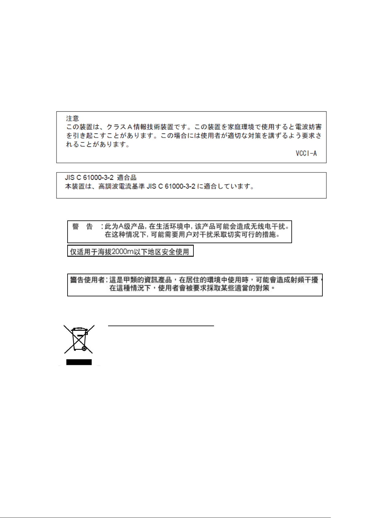
Japanese acceptance statement
Chinese acceptance statement
Taiwan acceptance statement
WEEE
Disposing of your used NEC product
In the European Union
EU-wide legislation as implemented in each Member State requires that used
electrical and electronic products carrying the mark (left) must be disposed of
separately from normal household waste. This includes tape library or electrical
components, such as tape drive, AC power supply.
When you dispose of such products, please follow the guidance of your local
authority or ask the shop where you purchased the product, or if applicable,
follow applicable legislation or agreement you may have.The mark on electrical
and electronic products may only apply to the current Europian Union Menber
States.
Outside the European Union
If you wish to dispose of used electrical and electronic products outside the
European Union, please contact your local authority and ask for the correct
method of disposal.
-i-
Page 3

FCC acceptance statement
This equipment has been tested and found to comply with the limits for a Class A digital device,
pursuant to Part 15 of the FCC Rules. These limits are designed to provide reasonable protection
against harmful interference when the equipment is operated in a commercial environment. This
equipment generates, uses, and can radiate radio frequency energy and, if not installed and used in
accordance with the instruction manual, may cause harmful interference to radio communications.
Operation of this equipment in a residential area is likely to cause harmful interference in which case
the user will be required to correct the interference at his own expense.
ICES acceptance statement
Industry Canada Class A Emission Compliance Statement/Avis de conformité à la réglementation
d`Industrie Canada:
CAN ICES-3(A) / NMB-3(A)
Other
Under the EN ISO 7779 standard, the maximum noise level is 70 decibels.
RoHS Compliance
This product complies with the EU's "Restriction of the use of certain hazardous substances in
electrical and electronic equipment" (RoHS).
Türkiye Cumhuriyeti:EEE Yönetmeliğine Uygundur
Complying with “CIRCULAR, No.30/2011/TT-BCT(Hanoi, August 10 2011), Temporary regulations
on content limit for certain hazardous substances in electrical products”
-ii-
Page 4
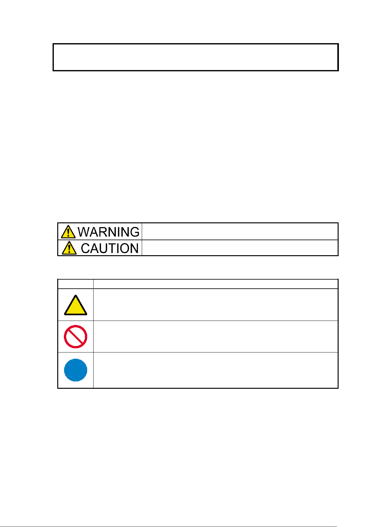
Safety Precautions
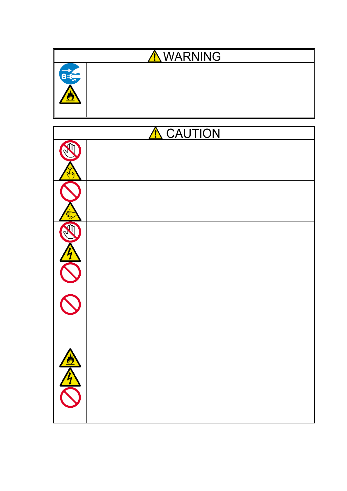
Indicates the presence of a hazard that may result in death or serious
personal injury if the instruction is ignored.
Indicates the presence of a hazard that may cause minor personal injury,
including burns, or property damage if the instruction is ignored.
SYMBOL
MEAN
This symbol indicates the presence of a hazard if the instruction is ignored. An image in
the symbol illustrates the hazard type. (Attention)
This symbol indicates prohibited actions. An image in the symbol illustrates a particular
prohibited action. (Prohibited Action)
This symbol indicates mandatory actions. An image in the symbol illustrates a mandatory
action to avoid a particular hazard. (Mandatory Action)
Before use, In order to use the product safely and correctly, be sure to read over this book, please handle it
properly.
This product has been designed with sufficient safety. In case of improper use of this product, the operator
may be injured and damage to property may result. After reading this manual, store it for future reference if
necessary.
Follow the instructions in this Guide for your safety to use the product.
The product contains components with possible danger, hazards that may cause by ignoring warnings, and
preventive actions against such hazards.
This product contains components with potential hazards, which are marked with a warning label placed on
or arount those components
In this Guide or warning labels, "WARNING" or "CAUTION" is used to indicate a degree of danger. These
terms are defined as follows:
Precautions and notices against hazards are presented with one of the following three symbols. The
individual symbols are defined as follows:
-iii-
Page 5
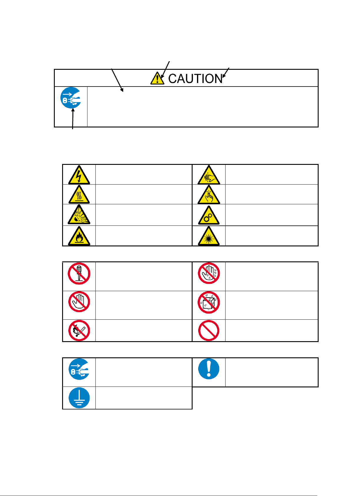
Disconnect the power cord(s) before installing or removing the product.
Make sure to power off the product and disconnect the power cord(s) from a power outlet
before installing/removing the server. All voltage is removed only when the power cords
are unplugged.
Indicates that improper use may
cause an electric shock.
Indicates that improper use may
cause fingers to be caught.
Indicates that improper use may
cause personal injury.
Indicates that improper use may
cause personal injury.
Indicates that improper use may
cause explosion or burst.
Indicates that improper use may
cause fingers or hands to be
caught.
Indicates that improper use may
cause fumes or fire.
Indicates that improper use may
cause eye damage.
Do not disassemble, repair, or
modify the server. Otherwise, an
electric shock or a fire may be
caused.
Do not touch the server
components with wet hand.
Otherwise, an electric shock may
be caused.
Do not touch any other component
than specified. Otherwise, an
electric shock or burn may be
caused.
Keep water or liquid away from
the server. Otherwise, an electric
shock or a fire may be caused.
Do not place the server near a fire.
Otherwise, a fire may be caused.
Indicates a general prohibited
action that cannot be specifically
identified.
Unplug the power cord of the
server. Otherwise, an electric shock
or a fire may be caused.
Indicates a mandatory action that
cannot be specifically identified.
Make sure to follow the
instruction.
Be sure to provide earthing.
Otherwise, an electric shock or a
fire may be caused.
Symbol indicating a prohibited
action (may not always be
indicated)
Description of a danger
Symbol to draw attention
Term indicating a degree of danger
(Example)
Attentions
Prohibited Actions
Mandatory Action
-iv-
Page 6
Do not use the product for services related to human lives or requiring high
reliability.
Your product is not intended to be used with or control facilities or devices concerning
human lives, including medical devices, nuclear facilities and devices, aeronautics and
space devices, transportation facilities and devices; and facilities and devices requiring
high reliability. NEC assumes no liability for any accident resulting in personal injury,
death, or property damage if the product has been used in the above conditions.
Do not use the product if any smoke, odor, or noise is present.
If smoke, odor, or noise is present, immediately turn off the product and disconnect the
power plug from the outlet, then contact your service representative. Using the product in
such conditions may cause a fire.
Keep needles or metal objects away from the product.
Keep needles or metal objects away from the product.
Do not insert needles or metal objects into ventilation holes or gaps in the product. Doing
so may cause an electric shock.
Do not use the product in any unapproved place.
Install the product on a standard EIA 19-inch rack assembly. Do not install the rack
containing the product in a place inappropriate to the rack installation environment. Failure
to follow these instructions may cause some bad influences to be imposed on the product
and other systems installed on the rack and also a fire or personal injury due to falling of
the rack may occur. For the detailed explanation on the place where the server should be
installed and the earthquake-resistant construction for the rack, refer to the manual attached
to the rack or contact you service representative.
Always install the product on a rack conforming to the relevant standard.
Install the product on a rack confirming to the EIA standard for the Server/Storage to be
used. Do not use the product installed on a rack that is not comply with EIA standard or
without mounting it on a proper rack. Failure to follow these instructions may cause the
server to operate incorrectly and/or personal injury or damages of surrounding devices to
occur. Contact your service representative for the racks available for the product.
Keep water or foreign matter away from the product.
Do not let any form of liquid (water etc.) or foreign matter (e.g., pins or paper clips) enter
the server. Failure to follow this warning may cause an electric shock, a fire, or a failure of
the server. When such things accidentally enter the server, immediately turn off the power
and disconnect the power plug from the outlet. Do not disassemble the product. Contact
your service representative.
General
-v-
Page 7
Do not overload the supply circuit by connecting this equipment with other
equipment so that the total exceeds the outlet rating.
To prevent fires, wiring and device damage, the total power drawn by the equipment in
the rack shall not exceed the rating of the branch circuit. Contact your electric constructor
or the local power company for the requirements on the wiring and installation of electric
facilities.
Do not carry or install the product only by a single person.
More than one person is required to carry or install the rack. Failure to follow this
instruction may cause the rack to fall to result in personal injury and/or breakages of
surrounding devices. In particular, a high rack (such as 44U rack) is unstable if it is not
fixed by stabilizers. More than one person is required to hold the rack to carry and install
the product.
Do not install the product so that the load may be concentrated on a specific
point.
Install stabilizers on the rack or connect more than one rack with each other to distribute
the load to avoid the weight is concentrated on one spot. Failure to follow this instruction
may cause the rack to fall to result in personal injury.
Do not install components on the product only by a single person.
More than one person is required to install parts including the doors and trays for the rack.
Failure to follow this instruction may cause some parts to fall to be broken and/or to result
in personal injury.
Anchor the equipment rack.
The equipment rack must be anchored (putting stabilizers or providing seismic protection)
to an unmovable support to prevent it from falling over when the product is removed from
the rack. The anchors must be able to withstand a force of up to 113kg (250lbs.) You must
also consider the weight of any other device installed in the rack.
Do not pull more than one device out of the rack at the same time.
Pulling out more than one device from the rack may cause the rack to be fallen. Only pull
out a single device from the rack at a time.
Rack
-vi-
Page 8
Elevated Operating Ambient.
If installed in a closed or multi-unit rack assembly, the operating ambient temperature of
the rack environment may be greater than room ambient. Therefore, consideration
should be given to installing the equipment in an environment compatible with the
maximum ambient temperature (Tma) specified by the manufacturer.
Reduced Air Flow.
Installation of the equipment in a rack should be such that the amount of air flow required
for safe operation of the equipment is not compromised.
Reliable Earthing.
Reliable earthing of rack-mounted equipment should be maintained. Particular attention
should be given to supply connections other than direct connections to the branch circuit
(e.g. use of power strips).
-vii-
Page 9
Do not hold the power plug with a wet hand.
Do not disconnect/connect the plug while your hands are wet. Failure to follow this
warning may cause an electric shock.
Do not connect the ground wire to a gas pipe.
Never connect the ground wire to a gas pipe. Failure to follow this warning may cause a
gas explosion.
If you disconnect the power, disconnect the two power lines.
The product might be powered from 2 AC power lines. If you disconnect the power from
the device, both 2 power sources must be disconnected. It may cause an electric shock if
the power is not disconnected properly.
Plug in to a proper power source.
Use a proper wall outlet. Use of an improper power source may cause a fire or a power
leak. Do not install the product where you need an extension cord. Use of a cord that does
not meet the power specifications of the product may heat up the cord and cause a fire.
Do not connect the power cord to an outlet that has an illegal number of
connections.
The electric current exceeding the rated flow overheats the outlet, which may cause a fire.
Insert the power plug into the outlet as far as it goes.
Heat generation resulting from a halfway inserted power plug (imperfect contact) may
cause a fire. Heat will also be generated if condensation is formed on dusty blades of the
halfway inserted plug, increasing the possibility of fire.
Do not use the attached power cord for any other devices or usage.
The power cord that comes with your product is designed aiming to connect with this
product and to use with the product, and its safety has been tested. Do not use the attached
power cord for any other purpose. Doing so may cause a fire or an electric shock.
Power Supply and Power Cord Use
-viii-
Page 10
Use the authorized power cord only.
Use only the power cord that comes with your product. Use of an unauthorized power
cord may cause a fire when the electric current exceeds the rated flow. Also, observe the
following to prevent an electric shock or a fire caused by a damaged cord.
・Do not stretch the cord harness.
・Do not pinch the power cord.
・Do not bend the power cord.
・Keep chemicals away from the power cord.
・Do not twist the power cord.
・Do not place any object on the power cord.
・Do not step on the power cord.
・Do not alter, modify, or repair the power cord.
・Do not bundle the power cords.
・Do not secure the power cord with staples or equivalents.
・Do not use any damaged power cord.
(Replace a damaged power cord with a new one of the same specifications. Ask your
service representative for replacement.)
-ix-
Page 11
Do not use or store this product in corrosive environment.
Avoid the usage or storage of this product in an environment which may be exposed to
corrosive gases, such as those including but not limited to: sulfur dioxide, hydrogen
sulfide, nitrogen dioxide, chlorine, ammonia and/or ozone. Avoid installing this product
in a dusty environment or one that may be exposed to corrosive materials such as sodium
chloride and/or sulfur. Avoid installing this product in an environment which may have
excessive metal flakes or conductive particles in the air. Such environments may cause
corrosion or short circuits within this product, resulting in not only damage to this
product, but may even lead to be a fire hazard. If there are any concerns regarding the
environment at the planned site of installation or storage, please contact your sales agent.
Do not install the product in any place other than specified.
Do not install the product in the following places or any place other than specified in this
Guide. Failure to follow this instruction may cause a fire.
・a dusty place
・a humid place such as near a boiler
・a place exposed to direct sunlight
・an unstable place
Do not install the parts other than specified.
Do not install third-party products or options on the device. Operation is no longer
successful, and may cause fire or malfunction.
Do not block the intake and exhaust holes.
Do not block air intake holes at the front or back of the product. Internal temperature rises
may cause malfunction and doing so may cause a fire.
Do not use any unauthorized interface cable.
Use only interface cables provided by NEC and locate a proper device and connector
before connecting a cable. Using an unauthorized cable or connecting the product to an
improper destination may result in a fire by short circuit. Also, observe the following
notes on using and connecting an interface cable.
・Do not step on the cable.
・Do not place any object on the cable.
・Do not use the device with loose cable connections.
・Do not use any damaged cable connector.
・Lock the cable certainly by the attachments such as screws.
Treat SAS cables with care and respect.
Rough treatment of SAS cables could cause deterioration of characteristics or mechanical
damage (line disconnection).
・Ensure a minimum bending radius of 150mm.
・Make sufficient allowance for the cable forming.
・Do not forcibly stretch a cable or otherwise stress it.
Installation, Relocation, Storage, and Connection
-x-
Page 12
Treat optical fiber cables with care and respect.
Rough treatment of optical fiber cables could cause deterioration of characteristics or
mechanical damage (line disconnection).
・Ensure a minimum bending radius of 38mm.
・Do not drop a cable on the floor or otherwise shock it.
・If not connecting a cable, place caps on it. When connecting a cable, do not discard the
caps but save them (as well as those for connectors on the unit).
As the optical power is attenuated by dust or dirt and it may cause data error, be sure to
clean the optical connector using the following procedure when optical fibre cable is
inserted to the product:
1. Spray air or another parts cleaning gas on the optical connector for several seconds.
2. Wipe the optical connector lightly several times with a non-fibrous cloth wetted with
isopropyl alcohol.
3. Spray parts cleaning gas on the optical connector for several seconds again.
Be careful when handling the laser products.
The product contains class-1 laser products based on JIS C6802, EN60825-1 (+A-11), and
21 CFR 1040.10 and 1040.11 issued by the U.S. Food and Drug Association (FDA).
Do not look straight at the optical fiber cable, optical fiber connector, or laser transceiver
module because there is a risk of eye damage, depending on the laser power level.
Note that JIS C6802, EN60825, and IEC60825 defines class-1 laser as the level of laser
which causes no injury if human is exposed to it.
Prevent damage from electrostatic discharge.
Components in the device is sensitive to static electricity. Even a slight discharge, could
damage the electrical components in the device. Even if a component receives damage, an
error may not occur immediately, but the state is aggravated and is causing a
"intermittent" problem gradually.
Before touching the product, touch an unpainted metal surface. It is effective to use
commercially available anti-static wrist strap with a clip terminal.
・If the frame of the device is metal, touch the frame.
・Otherwise, touch the wall part of the product or a screw of the door frame.
・Stay as still as possible when touching the components inside the product to avoid
produce static electricity.
Do not pinch your finger with rails or other components.
Be careful sufficiently not to pinch or cut your fingers with the rails etc. when you
mount/unmount the product on the rack.
Do not apply any load on the device pulled out from the rack.
Do not apply any load on the device pulled out from the rack. Doing so bends the frame of
the device. Consequently, the device cannot be pushed back into the rack. Placing an
object on the device may also cause personal injury if the device drops.
Relocation of the product.
Consult with your service representative for relocation of the product.
Disposal of the product.
The product contains liquid crystal display (LCD). Consult with your service
representative before disposing of the product. Dispose of the unit according to the
ordinance of the local government.
-xi-
Page 13
Do not disassemble, repair, or alter the product.
Never attempt to disassemble, repair, or alter the product on any occasion. Failure to
follow this instruction may cause an electric shock or fire as well as malfunctions of the
server.
Disconnect the power plug before cleaning the product.
Make sure to power off and disconnect the power plug from a power outlet before
cleaning product. Touching any internal components of the product with its power cord
connected to a power source may cause electric shock even if the product’s power is
offline. Disconnect the power plug from the outlet occasionally and clean the plug with a
dry cloth. Heat will be generated if condensation is formed on a dusty plug, which may
cause a fire.
Avoid installation in extreme temperature conditions.
Immediately after the device is powered off, its internal components are very hot. Please
work after confirming the product was cooled enough.
Make sure to complete installation.
Install power cords and interface cables surely.
Improper installation of the cords and cables may cause a contact failure, resulting in
smoking or fire.
Handling of damaged LCD (liquid crystal display)
The product uses the liquid crystal display that contains harmful liquid to the human body.
If you need to touch the damaged LCD, take extreme care not to touch the liquid inside
the display. If the liquid enters your mouth, immediately gargle and consult with your
doctor. If the liquid adheres your skin or eyes, rinse it for at least 15 minutes, and then
consult with your doctor.
Ask your service representative for repair of the LCD.
Cleaning and Working with Internal Devices
-xii-
Page 14
Do not use the product if any smoke, odor, or noise is present.
If smoke, odor, or noise is present, immediately turn off the product and disconnect the
power plug from the outlet, then contact your service representative. Using the product in
such conditions may cause a fire.
Do not put hand inside the device.
Do not put your hand inside the device. There is a possibility of injury by pinching your
hands with the internal components..
Stay away from the fan.
Keep your hand or hair away from the cooling fan on the rear of the product. Failure to
follow this warning may get your hand or hair caught in the fan, resulting in injury.
Avoid contact with the product during thunderstorms.
If it starts thundering before you disconnect the power plug, do not touch any part of the
product including the cables. Failure to follow this warning may cause an electric shock
by the thunderbolt.
Do not peep into device when magazine operations.
The part of the magazine has a mechanism to automatically open.
If you are peeping into the device during magazine operations, it may be injured part of
the magazine hit the face.
Do not put the finger in the opening of the magazine while operating the I/O
station.
The I/O station dashes out to a device front side after pressing the enter button. Please
there must not be danger from which the hand is placed between the moving part, and do
not affix the hand to the magazine, and do not put the finger in the opening of the
magazine until the I/O station dashes out. Please push the magazine a little when the
finger is placed in the opening of the magazine by any chance and pull out the finger
while returning it.
Keep any animal (Pet) away from the product.
Keep any animal (Pet) away from the product. Pet’s discharges or fur may enter the
device and cause a fire or electric shock.
To avoid incommoding reflections at visual display workplaces this device must
not be placed in the direct field of view.
This device is not intended for use in the direct field of view at visual display workplaces.
To avoid incommoding reflections at visual display workplaces this device must not be
placed in the direct field of view.
During Operation
-xiii-
Page 15
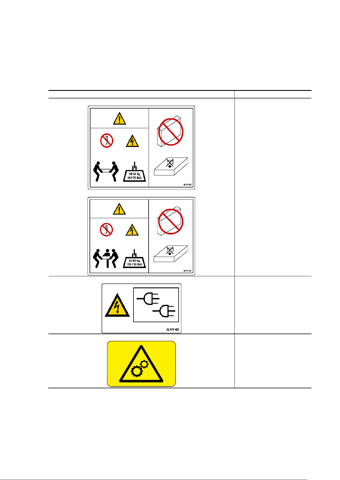
Warning Label
Meaning / Location
T30A
T60A
[Do not disassemble]
Only the maintenance
Personnelcan disassemble
the unit.
[Heavy load]
To avoid personal injury, at
least three persons must
carry the unit.
[Do not put the thing on]
Do not put the thing on the
device.
[Do not put on length.]
Do not put the device on
length.
Location: Top plate of the
unit
T60A
[Redundant power supply
use]
Location: back of device
T30A/T60A
[Attention that rolls hand and
finger]
Location:Drive
Warning Labels
The following warning labels have been attached to this unit. Customers and maintenance service personnel
are urged to keep these warnings in the forefront of their minds when operating this unit. (Do not remove or
soil these labels.)
If any of these labels are missing, removed, soiled, or otherwise unreadable, contact your local maintenance
service company.
-xiv-
Page 16
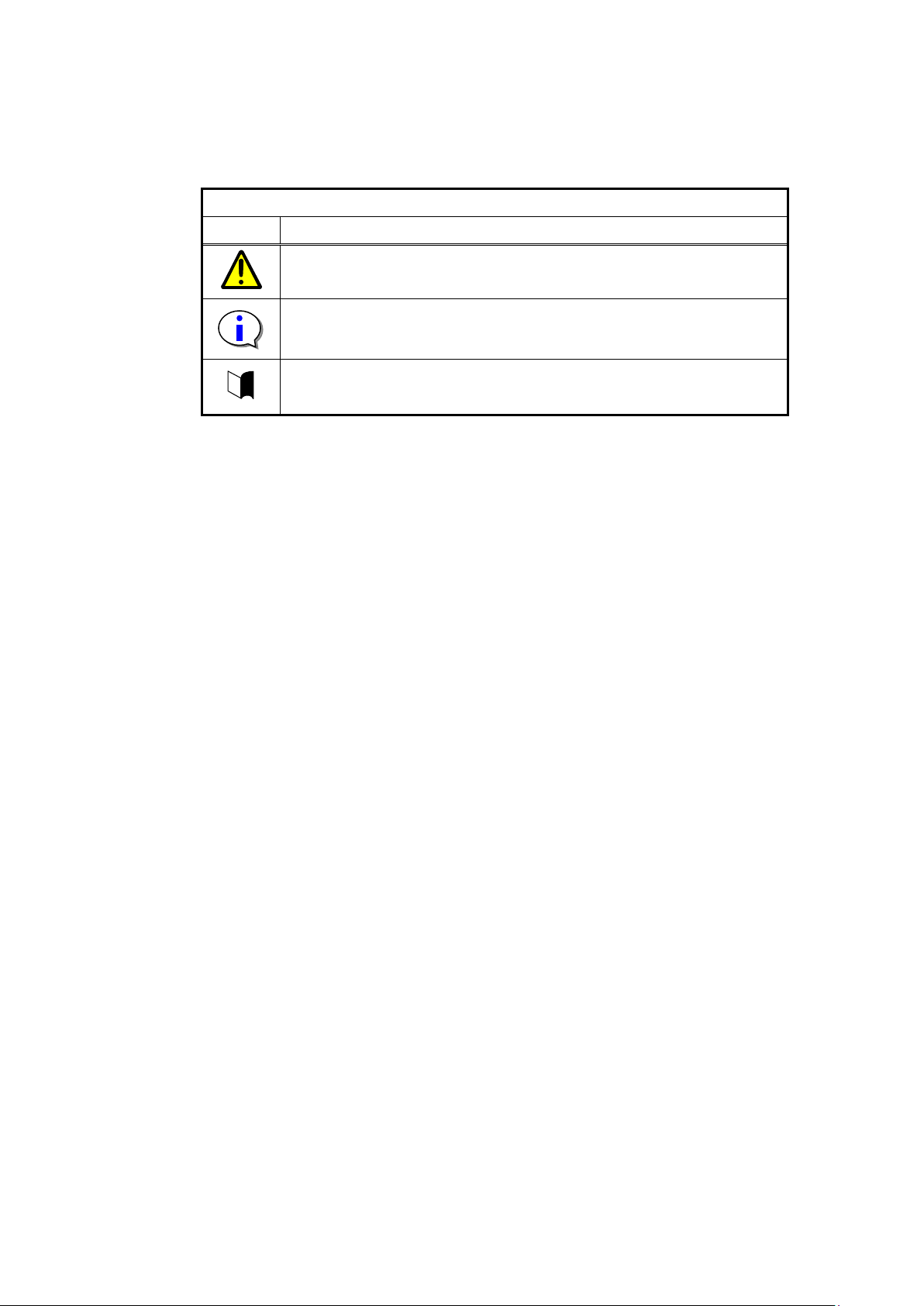
Kind of display
Kind
Content
It explains the content for which attention is especially necessary in
operating.
It explains information on the limitations in the operation.
It explains amplification of the text.
The mark of this manual
The following signs are used in this manual.
-xv-
Page 17

Contents
Handling of laser product .................................................................................................... i
Japanese acceptance statement ............................................................................................. i
Chinese acceptance statement .............................................................................................. i
Taiwan acceptance statement ............................................................................................... i
WEEE ................................................................................................................................ i
FCC acceptance statement .................................................................................................. ii
ICES acceptance statement ................................................................................................. ii
Other ................................................................................................................................ ii
RoHS Compliance ............................................................................................................. ii
Warning Labels ............................................................................................................... xiv
The mark of this manual ................................................................................................... xv
Contents ....................................................................................................................................... xvi
Figures ........................................................................................................................... xxi
Tables .......................................................................................................................... xxiii
Preface ....................................................................................................................................... xxiv
Remarks ....................................................................................................................... xxiv
Exemptions ................................................................................................................... xxv
Use Limitation ............................................................................................................... xxv
Chapter1 General Description ...................................................................................................... 1
1.1 Handling Precautions ................................................................................................................. 1
1.1.1 Notes on Use ....................................................................................................................... 1
1.2 Transfer of Library ..................................................................................................................... 1
1.3 Names and Features of Components ............................................................................................ 2
1.3.1 Front View .......................................................................................................................... 2
1.3.2 Operator panel ..................................................................................................................... 3
1.3.2.1 Status LED .................................................................................................................... 3
1.3.2.2 LCD .............................................................................................................................. 4
1.3.2.3 Button ........................................................................................................................... 4
1.3.3 Magazine operation panel ..................................................................................................... 5
1.3.3.1 Magazine Status LED ..................................................................................................... 5
1.3.3.2 Button ........................................................................................................................... 5
1.3.3.3 Ethernet connector for maintenance ................................................................................. 6
1.3.4 Magazine ............................................................................................................................ 7
1.3.4.1 Slot number ................................................................................................................... 7
1.3.4.2 Active Slot ..................................................................................................................... 8
1.3.4.3 I/O station ...................................................................................................................... 8
1.3.4.4 Escape slot ..................................................................................................................... 8
1.3.4.5 Cleaning Slot ................................................................................................................. 8
1.3.4.6 Inactive slot ................................................................................................................... 8
1.3.5 Rear View ........................................................................................................................... 9
1.3.6 Drive Sled Ingicator ........................................................................................................... 10
1.3.7 Power Module LED ............................................................................................................ 11
1.4 Encryption ............................................................................................................................... 12
1.5 Disposal of the Product and Comsumables ................................................................................. 13
1.6 Unpacking ............................................................................................................................... 14
1.6.1 Unpacking ........................................................................................................................ 14
1.7 Installing the Rack Mounting Kit .............................................................................................. 16
1.7.1 Components ...................................................................................................................... 16
1.7.2 Caution points for rack mounting ........................................................................................ 17
1.7.3 Rack mount rail attachment position ................................................................................... 19
1.7.4 Attachment of Rack mount rail L/R..................................................................................... 20
1.7.5 Attachment of Rack mount bracket L/R ............................................................................... 21
1.7.6 Installation of library ......................................................................................................... 22
1.7.7 Attachment of Rack ear ...................................................................................................... 24
-xvi-
Page 18

1.7.8 Attachment of label plate.................................................................................................... 25
1.8 Removal of shipment Stabilizer ................................................................................................. 26
Chapter2 Setup ......................................................................................................................... 27
2.1 Connection of a Interface Cable ................................................................................................ 27
2.1.1 Connection of SAS Cable ................................................................................................... 27
2.1.2 Connection of FC Cable ..................................................................................................... 28
2.2 Connection of AC Power Cable ................................................................................................ 29
2.3 Power-On and self test.............................................................................................................. 29
2.4 Setting Drive configuration ....................................................................................................... 29
2.5 Setting Library and Drive configuration ..................................................................................... 29
2.6 Diagnostic Test ........................................................................................................................ 30
2.7 Operation Checks after Installation ............................................................................................ 30
Chapter3 Power-On and Power-Off ............................................................................................ 31
3.1 Power-On and Power-On Sequence ........................................................................................... 31
3.2 Starting the System .................................................................................................................. 31
3.3 Shutting Down the System ........................................................................................................ 31
3.4 Power-Off and Power-Off Sequence .......................................................................................... 31
Chapter4 Operator Panel ........................................................................................................... 32
4.1 Panel Indications ...................................................................................................................... 32
4.1.1 Menu Screen ..................................................................................................................... 32
4.1.2 Status Display screen ......................................................................................................... 33
4.1.2.1 Library State ................................................................................................................ 33
4.1.2.2 Drive State ................................................................................................................... 37
4.1.3 Asynchronization message screen ....................................................................................... 39
4.2 Menu Tree ............................................................................................................................... 40
4.3 Login ...................................................................................................................................... 44
4.3.1 Service Login .................................................................................................................... 45
4.4 Top Menu ................................................................................................................................ 46
4.4.1 Commands ........................................................................................................................ 47
4.4.2 Configuration .................................................................................................................... 48
4.4.2.1 Library Settings ............................................................................................................ 49
4.4.2.2 Network Settings .......................................................................................................... 50
4.4.2.3 Drive Settings .............................................................................................................. 51
4.4.2.4 OP Panel Settings ......................................................................................................... 52
4.4.2.5 Date / Time .................................................................................................................. 52
4.4.2.6 Set Default ................................................................................................................... 52
4.4.3 Current Information ........................................................................................................... 53
4.4.3.1 Setting Information ....................................................................................................... 53
4.4.3.2 Slot Information ........................................................................................................... 53
4.4.4 Service .............................................................................................................................. 54
4.4.4.1 View Error Status ......................................................................................................... 54
4.4.4.2 Diagnostics .................................................................................................................. 54
4.4.4.3 Statistics ...................................................................................................................... 55
4.4.4.4 Telnet Service Port ....................................................................................................... 55
4.4.4.5 View Revision ............................................................................................................. 55
4.4.4.6 Drive Replacement ....................................................................................................... 55
4.4.4.7 Advanced Service ......................................................................................................... 56
4.4.4.8 Library Log ................................................................................................................. 56
4.4.5 Logout .............................................................................................................................. 56
4.5 Configuring the Library ............................................................................................................ 57
4.5.1 Viewing Configuration data of the library ............................................................................ 57
4.5.2 Change password ............................................................................................................... 57
4.5.3 Setting of Drive ................................................................................................................. 59
4.5.3.1 Setting of Serial Attached SCSI ..................................................................................... 59
4.5.3.2 Setting of Fibre Channel ............................................................................................... 60
4.5.3.3 Setting robot control path .............................................................................................. 61
4.5.3.4 Power Save Mode ........................................................................................................ 62
4.5.4 Switching between ONLINE and OFFLINE ........................................................................ 62
4.5.5 Setting of I/O Station ......................................................................................................... 63
-xvii-
Page 19

4.5.6 Setting of Active Slot ......................................................................................................... 63
4.6 Insertion and Removing Cartridge by Operator Panel ................................................................. 64
4.6.1 Magazine Operations ......................................................................................................... 64
4.6.1.1 Removing Magazine ..................................................................................................... 64
4.6.1.2 Insertion of cartridges into magazine .............................................................................. 66
4.6.1.3 Removal of cartridges from magazine ............................................................................ 66
4.6.1.4 Emergency removal of magazine ................................................................................... 67
4.6.2 I/O Station Operations ....................................................................................................... 68
4.7 Using the operation panel to move cartridges ............................................................................. 69
4.7.1 Load cartridge into drive .................................................................................................... 69
4.7.2 Removing from the drive.................................................................................................... 71
4.8 Cleaning .................................................................................................................................. 73
4.8.1 Cleaning by Operation panel .............................................................................................. 73
4.8.2 Auto Cleaning ................................................................................................................... 73
4.9 Rebooting the Library .............................................................................................................. 74
4.10 Rebooting Drive ..................................................................................................................... 75
Chapter5 Remote Manager Interface .......................................................................................... 76
5.1 Connection Configuration ......................................................................................................... 76
5.2 Connection Settings ................................................................................................................. 77
5.3 Startup of Remote Manager Interface ........................................................................................ 78
5.3.1 Connection of https ............................................................................................................ 79
5.4 Login Formats ......................................................................................................................... 80
5.5 Web Page Configuration ........................................................................................................... 81
5.6 Web Page Detail ...................................................................................................................... 82
5.6.1 Menu windows .................................................................................................................. 82
5.6.2 Login ................................................................................................................................ 83
5.6.3 Library information viewing menu(Monitor Sytem) ............................................................. 84
5.6.3.1 Library Basic Information(System Summary) ................................................................. 84
5.6.3.2 Library Detailed Information Window (Library Map) ..................................................... 86
5.6.4 Library management menu (Manage Library) ...................................................................... 93
5.6.4.1 Move Cartridge window (Move Cartridge) ..................................................................... 93
5.6.4.2 Unload Drive window (Unload Drive) ........................................................................... 95
5.6.4.3 Clean Drive window (Clean Drive) ................................................................................ 96
5.6.4.4 Library State (OFFLINE/ONLINE)switching window(Library State) ............................... 97
5.6.5 Library setting (Configure Library) ..................................................................................... 98
5.6.5.1 Account setting (User Access) ....................................................................................... 98
5.6.5.2 Physical View (Physical) ............................................................................................ 101
5.6.5.3 Library setup window (Logical)................................................................................... 102
5.6.5.4 Network setup window (Network) ............................................................................... 105
5.6.5.5 Date and Time setup window (Date and Time) ............................................................. 107
5.6.5.6 Event Notification setup window(SMTP) ..................................................................... 108
5.6.5.7 Event Notifications setup window (SNMP) .................................................................. 109
5.6.5.8 Encryption Basis ......................................................................................................... 112
5.6.5.9 Encryption Detail ........................................................................................................ 113
5.6.5.10 Licenses Registration ................................................................................................. 114
5.6.5.11 Saving the File Setting / Restore Screen (Save and Restore) .......................................... 115
5.6.6 Library maintenance (Service Library) ............................................................................... 117
5.6.6.1 View Library Logs ...................................................................................................... 117
5.6.6.2 Download Library /Drive logs (Download Logs) ........................................................... 118
5.6.6.3 Reset (Reset Library / Drive) ........................................................................................ 119
5.6.6.4 Firmware Refresh Screen (Firmware Update) ............................................................... 120
5.6.6.5 Statistical Information (Usage Statistics) ...................................................................... 121
5.6.6.6 Web Shell (web shell) ................................................................................................. 122
5.7 Event list ............................................................................................................................... 123
Chapter6 Encryption Key Management Function ...................................................................... 125
6.1 General Information ............................................................................................................... 125
6.1.1 Features of Encryption Key Management Option ............................................................... 125
6.1.2 Encryption Mechanism .................................................................................................... 125
6.1.3 Types of Keys ................................................................................................................. 125
-xviii-
Page 20

6.1.3.1 Master Key ................................................................................................................ 126
6.1.3.2 Encryption Key .......................................................................................................... 127
6.1.3.3 Backup of encryption key ........................................................................................... 127
6.2 Basic Operation of encryption key management function .......................................................... 128
6.2.1 Setup .............................................................................................................................. 128
6.2.1.1 Registering the activation key ...................................................................................... 129
6.2.1.2 Checking the license key registration status .................................................................. 129
6.2.1.3 Enabling the encryption key management function ....................................................... 130
6.2.1.4 Registering (importing) the master key......................................................................... 131
6.2.1.5 Exporting (backing up) the master key ......................................................................... 133
6.2.2 Operation ........................................................................................................................ 134
6.2.2.1 To Create encrypted medium ....................................................................................... 134
6.2.3 Checking tape media Information ..................................................................................... 135
6.2.3.1 Sharing tape medium among multiple libraries ............................................................. 135
6.2.4 Maintenance .................................................................................................................... 135
6.2.4.1 Backup of Encryption Key (Basic Operation) ............................................................... 135
6.2.4.2 Executing Set Default ................................................................................................. 136
6.2.4.3 Checking the encryption log ........................................................................................ 136
6.3 Advance Operation of encryption key management function ..................................................... 137
6.3.1 Enabling or Disableing Enctyption for Each tape medium................................................... 138
6.3.1.1 Setting tape medium encryption................................................................................... 139
6.3.1.2 Sharing tape medium among multiple libraries (advanced) ............................................ 140
6.3.2 Importing and Exporting the Encryption Key(For Each Tape Medium) ................................ 140
6.3.2.1 When to import the encryption key .............................................................................. 141
6.3.2.2 To import the encryption key ...................................................................................... 141
6.3.2.3 To export an encryption key ........................................................................................ 143
6.3.3 Disabling the Encryption Management Function for the Library .......................................... 144
6.3.4 Changing the Master Key ................................................................................................. 145
6.3.5 Backing Up and Restoring the KEY Database .................................................................... 145
6.3.5.1 Backing up the KEY database ..................................................................................... 146
6.3.5.2 Restoring the KEY database ........................................................................................ 146
6.3.6 Clearing encryption information ....................................................................................... 147
6.3.6.1 To clear encryption information................................................................................... 147
6.4 Points to Check When a Failure or Abnormality Occurs ............................................................ 148
6.5 FAQ about Encryption Key Management function ................................................................... 149
6.6 List of Encryption Event Log Messages ................................................................................... 150
Chapter7 Installation of Option ................................................................................................ 151
7.1 Install of drive ....................................................................................................................... 151
7.2 Install of power module .......................................................................................................... 151
7.3 Install of activation key .......................................................................................................... 152
Chapter8 Cartridges ................................................................................................................ 152
8.1.1 Data Cartridge ................................................................................................................. 153
8.1.2 WORM cartridge ............................................................................................................. 153
8.1.3 Cleaning cartridge ........................................................................................................... 153
8.1.4 Diagnosis cartridge .......................................................................................................... 153
8.2 Cartridge Label ...................................................................................................................... 154
8.2.1 Attaching a cartridge label ................................................................................................ 155
8.3 Write Protection ..................................................................................................................... 156
8.4 Notes on Handling ................................................................................................................. 157
8.4.1 Notes on Use ................................................................................................................... 157
8.4.2 General ........................................................................................................................... 157
8.4.3 Use protection standard .................................................................................................... 157
8.4.4 Service Life ..................................................................................................................... 158
8.4.5 Cartridge storage ............................................................................................................. 158
Chapter9 Maintenance............................................................................................................. 159
9.1 Drive Cleaning ...................................................................................................................... 159
9.1.1 Auto Cleaning ................................................................................................................. 159
9.2 Diagnosis test ........................................................................................................................ 160
9.3 Cleaning of device ................................................................................................................. 160
-xix-
Page 21

9.4 Cleaning of Magazine Filter .................................................................................................... 161
9.5 Cleaning of cartridge .............................................................................................................. 161
9.6 Updating the Firmware ........................................................................................................... 162
9.6.1 Confirming the Firmware Version ..................................................................................... 162
9.6.2 Updating the Library Firmware ......................................................................................... 163
9.6.3 Updating the Drive Firmware ........................................................................................... 164
9.7 Troubleshooting Procedures .................................................................................................... 165
9.8 Moving the Library ................................................................................................................ 166
Chapter10 Replacing Maintenance Parts ................................................................................... 167
10.1 Saving and Restoring Maintenance Information ...................................................................... 168
10.1.1 Saving Maintenance Information .................................................................................... 168
10.1.2 Restoring Maintenance Information ................................................................................ 169
10.2 Replacing the Device ............................................................................................................ 170
10.3 Replacing the Maintenance Chassis ....................................................................................... 170
10.4 Replacing the Contoller Board .............................................................................................. 171
10.5 Replacing the Drive Module ................................................................................................. 173
10.6 Replacing the Power Supply Module ..................................................................................... 174
10.7 Replacing the Operator Panel PKG ........................................................................................ 175
10.8 Replacing the Escape Slot ..................................................................................................... 177
10.9 Replacing the Front Magazine and Rear Magazine ................................................................. 177
10.10 Replacing the Air Filter ...................................................................................................... 178
10.11 Replacing the Drive fan ...................................................................................................... 181
10.12 Replacing the Internal FC cable ........................................................................................... 184
10.13 Replacing the Front bezel L................................................................................................. 185
10.14 Replacing the Front bezel R ................................................................................................ 186
Chapter11 Self-Diagnosis Function .......................................................................................... 187
11.1 Mechanism Test ................................................................................................................... 187
11.1.1 Demo (Slot-Drv-Slot) ..................................................................................................... 187
11.1.2 Demo (Slot-Slot) ........................................................................................................... 187
11.1.3 MSBF Test .................................................................................................................... 187
11.1.4 X-Move Test ................................................................................................................. 187
11.1.5 Y-Move Test ................................................................................................................. 187
11.1.6 Pick/Put Test ................................................................................................................. 187
11.1.7 Pick/Put/Move Test ........................................................................................................ 187
11.1.8 Vibration Test ............................................................................................................... 187
11.2 LCD/LED Test .................................................................................................................... 187
11.3 Phy Test .............................................................................................................................. 187
Chapter12 Action in breakdown and abnormal circumstances .................................................... 188
12.1 Trouble Shooting ................................................................................................................. 189
12.2 When you request maintenance ............................................................................................. 190
-xx-
Page 22

Figures
Figure 1-1 Front of the Library (Above: T30A/Below: T60A) ......................................................... 2
Figure 1-2 Operator panel ............................................................................................................. 3
Figure 1-3 Magazine operation panel(left:T30A,right:T60A) .......................................................... 5
Figure 1-4 Slot Number of Magazine(Above:T30A,Below:T60A) ................................................... 7
Figure 1-5 Components on the Rear of the Library(T30A) .............................................................. 9
Figure 1-6 Components on the Rear of the Library(T60A) .............................................................. 9
Figure 1-7 Components of Rack mount kit parts ........................................................................... 16
Figure 1-8 Illustration of Rack Bars ............................................................................................ 17
Figure 1-9 Rack Dimensions ....................................................................................................... 18
Figure 1-10 Rack mount rail attachment position.......................................................................... 19
Figure 1-11 attachment of rack mount rails .................................................................................. 20
Figure 1-12 attachment of rack mount bracket R(left:T30A , right :T60A) ...................................... 21
Figure 1-13 attachment of rack mount bracket L(left:T30A , right :T60A) ...................................... 21
Figure 1-14 Mounting of library onto rack ................................................................................... 22
Figure 1-15 attachment of rack ears ............................................................................................. 23
Figure 1-16 Fastening of Library’s front side ............................................................................... 24
Figure 1-17 attachment of label plate ........................................................................................... 25
Figure 4-1 Menu Screen ............................................................................................................. 32
Figure 4-2 Component of Operator Panel ..................................................................................... 33
Figure 4-3 Accessor Icon ............................................................................................................ 34
Figure 4-4 Magazine Icon ........................................................................................................... 35
Figure 4-5 Magazine Icon(Magazine is Opened) .......................................................................... 35
Figure 4-6 Magazine Icon(I/O Station is set) ................................................................................ 35
Figure 4-7 Magazine Icon (I/O Station is opened) ........................................................................ 36
Figure 4-8 Magazine Icon(Slot Image) ........................................................................................ 36
Figure 4-9 Root screen of Top Menu ........................................................................................... 46
Figure 4-10 Move Cartidge ......................................................................................................... 69
Figure 4-11 Select source Screen................................................................................................. 69
Figure 4-12 Select Destination Screen ......................................................................................... 70
Figure 4-13 Select Execute ......................................................................................................... 70
Figure 4-14 Move Cartridge ....................................................................................................... 71
Figure 4-15 Select source screen ................................................................................................. 71
Figure 4-16 Select Destination screen .......................................................................................... 72
Figure 4-17 Select Execute ......................................................................................................... 72
Figure 4-18 Reboot Library ........................................................................................................ 74
Figure 5-1 Input URL................................................................................................................. 78
Figure 5-2 Login page(before entry) ............................................................................................ 83
Figure 5-3 Login page(after entry) .............................................................................................. 83
Figure 5-4 Library Basic Information Window ............................................................................. 84
Figure 5-5 Library map .............................................................................................................. 86
Figure 5-6 Detail(Magazine) ....................................................................................................... 87
Figure 5-7 Accessor Information ................................................................................................. 88
Figure 5-8 Library information ................................................................................................... 89
Figure 5-9 Network information.................................................................................................. 90
Figure 5-10 Notification information ........................................................................................... 91
Figure 5-11 Drive information .................................................................................................... 92
Figure 5-12 Move Cartridge ....................................................................................................... 93
Figure 5-13 Unload Drive ........................................................................................................... 95
Figure 5-14 Clean Drive ............................................................................................................. 96
Figure 5-15 Library state ............................................................................................................ 97
Figure 5-16 confirmation screen.................................................................................................. 97
Figure 5-17 UserAccess ............................................................................................................. 98
Figure 5-18 Add a User .............................................................................................................. 99
Figure 5-19 Remove a User confirmation screen ........................................................................ 100
Figure 5-20 Physical ................................................................................................................ 101
Figure 5-21 Logcal .................................................................................................................. 102
Figure 5-22 Network setup ....................................................................................................... 105
-xxi-
Page 23

Figure 5-23 Date and Time setup .............................................................................................. 107
Figure 5-24 SMTP setup ........................................................................................................... 108
Figure 5-25 SNMP setup .......................................................................................................... 109
Figure 5-26 SNMPv3 setup ....................................................................................................... 110
Figure 5-27 Trap list.................................................................................................................. 111
Figure 5-28 Encryption Basis setup ............................................................................................ 112
Figure 5-29 Encryption Detail setup ........................................................................................... 113
Figure 5-30 Licenses Registration .............................................................................................. 114
Figure 5-31 Save/Restore .......................................................................................................... 115
Figure 5-32 View Library logs ................................................................................................... 117
Figure 5-33 Download Logs ...................................................................................................... 118
Figure 5-34 Reset Library / Drive............................................................................................... 119
Figure 5-35 Firmware Update ................................................................................................... 120
Figure 5-36 Usage Statistics ..................................................................................................... 121
Figure 5-37 Web Shell .............................................................................................................. 122
Figure 6-1 activation key is not registered .................................................................................. 129
Figure 6-2 activation key is registered ....................................................................................... 129
Figure 6-3 Encryption Enable ................................................................................................... 130
Figure 6-4 Master key is registered ........................................................................................... 130
Figure 6-5 Manual Input of Master key...................................................................................... 131
Figure 6-6 File Input of Master key ........................................................................................... 132
Figure 6-7 Export of Master key ............................................................................................... 133
Figure 6-8 Encryption Detail .................................................................................................... 134
Figure 6-9 Encryption Detail .................................................................................................... 138
Figure 6-10 Encryption Setting ................................................................................................. 139
Figure 6-11 manual inputting of the encryption key .................................................................... 141
Figure 6-12 file inputting of the encryption key .......................................................................... 142
Figure 6-13 Export of the encryption key ................................................................................... 143
Figure 6-14 Disabling the Encryption Management Function ...................................................... 144
Figure 6-15 Changing Master Key ............................................................................................ 145
Figure 6-16 Backup or Restore of KEY Database ....................................................................... 145
Figure 6-17 Backup of KEY Database ....................................................................................... 146
Figure 6-18 Clear of Encryption information ............................................................................. 147
Figure 8-1 Names of Cartridge Parts ......................................................................................... 152
Figure 8-2 Data Cartridge Label ................................................................................................ 154
Figure 8-3 Attaching a cartridge label ........................................................................................ 155
Figure 8-4 Write Protection of cartridge ..................................................................................... 156
Figure 9-1 Confirming the Firmware Version ............................................................................. 162
Figure 9-2 Firmware Update Window (Library Firmware Update) ............................................... 163
Figure 9-3 Firmware Update Window (Drive Firmware Update) ................................................. 164
Figure 10-1 Save/Restore Window ............................................................................................ 168
Figure 10-2 Save/Restore Window ............................................................................................ 169
-xxii-
Page 24

Tables
Table 1-1 Status LED on OperatorPanel......................................................................................... 3
Table 1-2 Button on OperatorPanel ............................................................................................... 4
Table 1-3 Status LED on Magazine Operation panel ....................................................................... 5
Table 1-4 Button on Magazine Operation panel .............................................................................. 5
Table 1-5 Drive Sled ingicator .................................................................................................... 10
Table 1-6 component list of rack mount kit parts .......................................................................... 16
Table 1-7 internal Dimension Requirements for rack .................................................................... 18
Table 2-1 Setting item ................................................................................................................ 29
Table 4-1 Library Status displayed in the Operation Panel ............................................................. 34
Table 4-2 Drive Status Icons ....................................................................................................... 36
Table 4-3 Drive Status Icons ....................................................................................................... 37
Table 4-4 Drive Message ............................................................................................................ 37
Table 4-5 Asynchronization Message .......................................................................................... 39
Table 4-6 Menu tree of commands .............................................................................................. 40
Table 4-7 Menu tree of configuration .......................................................................................... 41
Table 4-8 Menu tree of current information .................................................................................. 42
Table 4-9 Menu tree of Service ................................................................................................... 43
Table 4-10 Menu tree of logout ................................................................................................... 43
Table 4-11 Commands Submenus ............................................................................................... 47
Table 4-12 Configuration Submenus ........................................................................................... 48
Table 4-13 Library Setting Submenu ........................................................................................... 49
Table 4-14 Network Setting Submenu ......................................................................................... 50
Table 4-15 IPv4 Setting Submenu ............................................................................................... 50
Table 4-16 IPv6 Setting Submenu ............................................................................................... 50
Table 4-17 Drive Settings Submenu ............................................................................................ 51
Table 4-18 port setting submenu ................................................................................................. 51
Table 4-19 OP Panel Settings Submenu ....................................................................................... 52
Table 4-20 Date / Time Submenu ................................................................................................ 52
Table 4-21 Current Information submenu..................................................................................... 53
Table 4-22 Information to be displayed on Setting Information menu............................................. 53
Table 4-23 Information to be displayed on Slot Information menu ................................................. 53
Table 4-24 Service submenu ....................................................................................................... 54
Table 4-25 Information to be displayed on View Error Status ........................................................ 54
Table 4-26 Diagnostics ............................................................................................................... 54
Table 4-27 Information to be displayed on Statistics ..................................................................... 55
Table 4-28 Information to be displayed on View Revision ............................................................. 55
Table 4-29 Test to be displayed on Advanced Service ................................................................... 56
Table 4-30 Information to be displayed on View Revision ............................................................. 56
Table 5-1 Connection Setting (IPv4) ............................................................................................ 77
Table 5-2 Connection Setting (IPv6) ............................................................................................ 77
Table 5-3 Menus available at various user access levels ................................................................ 82
Table 5-4 Event List ................................................................................................................. 123
Table 5-5 Event List ................................................................................................................. 124
Table 6-1 Troubleshooting Table ............................................................................................... 148
Table 8-1 Drive/Cartridge Compatibility .................................................................................... 153
Table 8-2 Cartridge label code .................................................................................................. 154
Table 10-1 Maintenance Parts List ............................................................................................ 167
-xxiii-
Page 25

Preface
This User's Guide describes the operation (mainly for the hardware) of the T30A and T60A Tape
Library (hereinafter called "T30A Library" or "T60ALibrary" or ”Library”).
Refer to the manual of the backup software for commands and console messages of backup software.
This manual is intended for the operator of the library, however, it provides useful information
for system programmer and system administrator of the computer.
1st edition,September 2016
Remarks
(1) Trademarks
- Linear Tape-Open, LTO, Ultrium are trademarks of Hewlett-Packard Company, International
Business Machines Corporation, and Quantum of the U.S.A.
- IBM is a registered trademark of International Business Machines Corporation of the U.S.A.
- HP is registered trademarks of Hewlett-Packard Company of the U.S.A. in the United States.
- Windows is registered trademarks of Microsoft Corporation in the United States and other
countries.
- Java and other Java-based names and logos are trademarks or registered trademarks of Oracle
Corporation, Inc. in the United States and other countries.
This manual describes neither nor clearly.
(2) No part of this manual may be reproduced in any form without the prior written permissi
on of NEC Corporation.
(3) The contents of this manual may be revised without prior notice.
(4) The contents of this manual shall not be copied or altered without the prior written permi
ssion of NEC Corporation.
(5) All efforts have been made to ensure the accuracy of all information in this manual. If y
ou notice any part unclear, incorrect, or omitted in this manual, contact the service represe
ntative where you purchased this product.
-xxiv-
Page 26

Exemptions
(1) NEC assumes no liability arising from the use of this product, nor any liability for incidental or
consequential damages arising from the use of this manual regardless of Item (5) on the previous
page.
(2) NEC assumes no liability for the data stored in memory (data cartridge) regardless of existence of
an error or a failure.
(3) NEC assumes no liability for the damages caused by an earthquake, fires beyond our
responsibility, action by the third party, other accidents, customers' intended or unintended faults,
incorrect operation, and other uses under abnormal conditions.
(4) NEC assumes no liability for the accompanying damages (e.g., profit loss or business
interruption) arising from the use or unserviceable state.
(5) NEC assumes no liability for the damages caused by ignoring the description in this manual.
(6) NEC assumes no liability for the damages arising from the malfunction of the unit caused by the
use of an unauthorized devices and/or software.
Use Limitation
(1) This product is not intended to be used for the system which includes the devices which may
directly affect human lives. Do not use the product for such a purpose.
(2) Special consideration for the operation, maintenance, and management of the system are required
when this product is used for the system including the devices which may affect human safety
and public facility. Contact your service representative for such a case.
-xxv-
Page 27

This page is intentionally blank.
-xxvi-
Page 28

Chapter1 General Description
This chapter describes the major hardware components of the library system and the system
specifications.
The T30A tape library is an automated tape management system that contains one or two LTO
Ultrium drives. This library can house up to 30 cartridges.
The T60A tape library is an automated tape management system that contains one to four LTO
Ultrium drives. This library can house up to 60 cartridges.
1.1 Handling Precautions
Follow the instructions below to ensure that the product operates normally.
1.1.1 Notes on Use
The product has a cooling fan on the back. Do not obstruct the air vent or use the product in a
badly ventilated place. Do not store or use the product in an extremely hot place or a place
subject to sudden changes in temperature.
The product is made up of precision electronic components. Avoid applying shock to the
product, and do not store or use the product in a place subject to vibration.
Do not store or use the product in a place where it might come into contact with chemical
substances or vaporized chemicals.
Do not move or transport the product with its power on.
Do not store or use the product with heavy objects placed on it.
Do not turn off the power to the product while it is operating.
Do not insert cartridges in the magazine that do not comply with the product specifications.
1.2 Transfer of Library
When transferring (or selling) the product or any of its accessories to a third party, follow the
instructions below.
Main unit
When transferring (or selling) the product to a third party, be sure to also provide this guide.
Accessories
Since all accessories are required for setup and other procedures, they should be provided as well.
-1-
Page 29
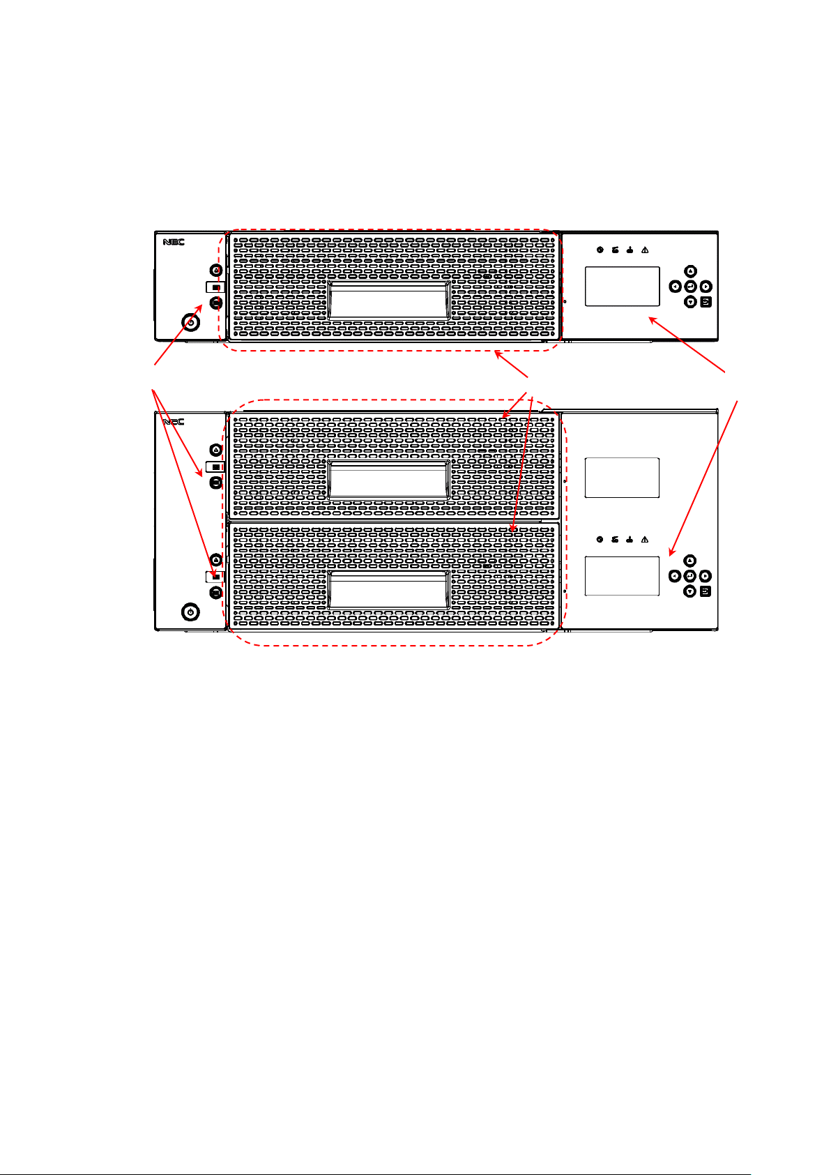
(1)
(2)
(3)
1.3 Names and Features of Components
This section shows the location of each component of the library and outlines its operation.
For information about how to mount the library in the rack, see "1.7Installing the Rack Mounting
Kit.")
1.3.1 Front View
Figure 1-1 Front of the Library (Above: T30A/Below: T60A)
(1).Magazine operation panel
(When the front panel is removed, the Ethernet connector for maintenance is found inside.)
(2).Magazine
(T30A has one magazine, and T60A has two magazines (upper and lower).)
(3).Operator panel
-2-
Page 30
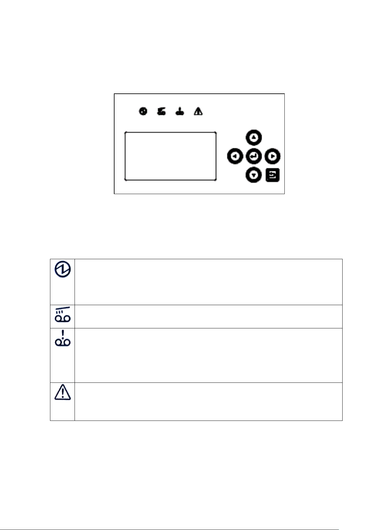
Ready indicator
This Green LED is on when library is ready state to the host.
On :Ready
Blinking : Library being initialized or an inventory is being taken
:The accessor moves by the command from the host/WEB/operator panel
: Initialize the drive / Diagnosing / Magazine is opend / Library is offline state.
Drive cleaning indicator
Lighting:The drive is requesting cleaning.
Blinking:The drive is being cleaned.
Cartridge error indicator
Lighting:This Orange LED is on when the cartridge error has been detected.
When SCD=6/7/J is reported in cartridge Load to Drive.
When Cleaning cartridge is used 50 times or more.
Turning off method:Magazine opening and shutting
Attention:After it is opened and shut,this LED doesn’t light even if the cartridge judged to be
abnormal before is turned on again in the magazine. (similar in case of I/O station)
Library error indicator
Lighting:This Orange LED in on when drive or accessor error has been detected.
Blinking:The library has recovered from error.
Turning off method:After the library has recovered(Blinking),please execute a warning off from
operator panel.(refer to 4.4.1)
1.3.2 Operator panel
The operator panel has LEDs that indicate the status of the library, an LCD panel that displays the
library status, operations, messages, library settings, error messages, etc., and buttons used to operate the
library.
Figure 1-2 Operator panel
1.3.2.1 Status LED
The following four LEDs are included in the operation panel.
Table 1-1 Status LED on OperatorPanel
-3-
Page 31

Direction button
It is used for the selection of the operation menu and the cursor position movement.
Enter button
Use this button to select the item currently indicated by the cursor. Also use this button to
determine the selected menu or value.
Cancel button
Use this button to cancel the selected menu or value or to return to the previous (upper
level) menu.
1.3.2.2 LCD
The LCD panel displays the library state, operations, messages, library settings, error messages, etc.
The LCD panel has a built-in backlight LED and is backlit when the operator panel is used.
If you disable the Auto Backlight OFF function on the OP Panel Settings menu, the backlight is
automatically turned off if the specified time elapses without any operation being performed.
1.3.2.3 Button
Table 1-2 Button on OperatorPanel
-4-
Page 32

This LED indicates the internal status of the I/O station.
When the I/O station is closed:
On: The I/O station contains one or more cartridges.
Off: The I/O station contains no cartridge.
When the I/O station is open, the LED is off. The color of the LED is green.
Magazine unlock button / indicator
Magazine unlock request button.
This Green LED is on when the button is enabled.
I/O Station unlock button / indicator
I/O station unlock request button.
This Green LED is on when the button is enabled.
After the unlock button is pressed, the I/O station is unlocked by the enter button
pressing.
LED of the unlock button blinks until the decision button is pressed.
Power button / indicator
Button to power on / off.
This LED is orange when power is being supplied, or the LED is green lighting when
power is on.
1.3.3 Magazine operation panel
Figure 1-3 Magazine operation panel(left:T30A,right:T60A)
1.3.3.1 Magazine Status LED
1.3.3.2 Button
Table 1-3 Status LED on Magazine Operation panel
Table 1-4 Button on Magazine Operation panel
-5-
Page 33

1.3.3.3 Ethernet connector for maintenance
When the front bezel of the magazine operation panel is removed, the Ethernet connector for
maintenance is found inside.
The Ethernet connector for maintenance is used for logging in to the remote management interface
as a user with maintenance personnel authority. (The IP address of the maintenance port is
192.0.2.1.)
In the Ethernet connector for maintenance, a remote administration interface can be used like the
Ethernet connector on the back of equipment.
For information about how to remove the front bezel of the magazine operation panel, see
"10.13Replacing the Front bezel L."
-6-
Page 34

1.3.4 Magazine
There are two types of magazines: one can hold 18 cartridges, and the other can hold 12 cartridges.
The library houses the 18-cartridge-type magazine in the front and the 12-cartridge-type magazine in
the back.
The 18-cartridge-type magazine has nine columns, and the 12-cartridge-type magazine has six
columns. Each column can hold two tape cartridges inserted end to end.
When two or more drives are mounted, the drive slot is used as the escape slot. When only one
drive is mounted, an escape slot module is provided for temporarily storing tape cartridges.
1.3.4.1 Slot number
The slot numbers range from 1 to 30 for T30A and from 1 to 60 for T60A. In each column, the
slot in the back has the smaller slot number.
When a column contains one tape cartridge, that tape cartridge is housed in the front slot and an odd
number is assigned to this slot. When another tape cartridge is inserted into the same column, the
previously inserted tape cartridge is moved to the back slot and the slot number of this back slot
changes to an odd number. An even number is assigned to the front slot that now contains the newly
inserted tape cartridge.
Figure 1-4 Slot Number of Magazine(Above:T30A,Below:T60A)
-7-
Page 35

1.3.4.2 Active Slot
This slot is used to store a data cartridge.
There are as many active slots as the value of Active Slots specified from the operator panel. For
details, see "4.4.2.1 Library Settings”
1.3.4.3 I/O station
This slot is used to insert tape cartridges into the library as well as to eject tape cartridges.
You can set whether to enable or disable the I/O station from the operator panel. For details, see
“4.4.2.1Library Settings”
If you enable the I/O station, the magazine slot numbers shown below are assigned to the I/O station
slots.
Slot numbers: 29/30 for T30A; 59/60 for T60A.
By default, the I/O station function is disabled.
1.3.4.4 Escape slot
This slot is used to temporarily store tape cartridges when moving tape cartridges inside this product.
When only one drive is mounted, an escape slot module is provided at the location where an additional
drive is usually mounted and this module is used as the escape slot.
When two or more drives are mounted, the drive slot is used as the escape slot.
1.3.4.5 Cleaning Slot
This slot contains a cleaning cartridge for auto cleaning. Since auto cleaning is not available, this
slot is normally not used.
If you enable auto cleaning from the operator panel or remote management interface, the inactive
slot containing a cleaning cartridge is automatically assigned as the cleaning slot. (A barcode label is
used to judge whether a cartridge is a cleaning cartridge. A cleaning cartridge without a barcode
label is not recognized as such.)
1.3.4.6 Inactive slot
This slot is one that fits none of the above descriptions.
When auto cleaning is enabled, an inactive slot is used as the cleaning slot.
For information about the auto cleaning function, see "4.8.2Auto Cleaning”
By default, the number of inactive slots is "0".
-8-
Page 36

(1)
(2)
(3)
(4)
(5)
(6)
(7)
(8)
1.3.5 Rear View
Figure 1-5 Components on the Rear of the Library(T30A)
Figure 1-6 Components on the Rear of the Library(T60A)
(1)Power supply (In case of T60A,the redundant power supply might be installed)
(2).AC power connector
(3).Drive
(4).Drive Sled indicator (refer to 1.3.6)
(5).SAS access port or FC access port
SAS Drive: Two connectors are mounted on the device back and forth.
(front :port A, back:port B(not use))
FC Drive: Two connectors are mounted on the vertical direction of the device.
(upper : port A, lower:port B(not use))
(6).Ethernet access port
(7).Fastening screw for transportation
(8).Interface cable fastener (to be used for fastening the interface cable as necessary)
-9-
Page 37

LED indicating the status and maintenance requirements
On :Maintenance request status.
Off :normal.
LED indicating the status of power supply
On :Power is supplied.
Off :Power is not supplied.
LED indicates the communication status to the library
On :Recognized from the library.
Blinking :Data transfer.
Off :Not recognized from the library.
LED indicating the status of the cartridge
On :Cartridge exist.
Off :No cartridge.
LED indicating the connection status with host.
On :Connected to the host.
Blinking :Data transfer or initializing state.
Off :Port closed or disconnected to the host.
1.3.6 Drive Sled Ingicator
These indicate the states of the drive.
Table 1-5 Drive Sled ingicator
-10-
Page 38

1.3.7 Power Module LED
Three LED that shows the following is mounted on the back side of the power source module.
・AC:When the AC voltage is supplied, it lights.
・DC:When the DC voltage is supplied, it lights.
・Alarm:When abnormality occurs by the power source module, it lights.
-11-
Page 39

1.4 Encryption
This function allows you to encrypt cartridges by setting either an encryption key automatically
generated from the master key or a separately specified encryption key to the drive.
The library stores encryption keys and manages them individually on a cartridge-by-cartridge basis
using barcode labels.
This function is disabled by default. It is enabled when a license key is input from the remote
management interface.
When enabled, the encryption function behaves as follows:
Setting the encryption function requires administrator authority.
The library has a database that can hold encryption keys for 2000 cartridges.
If an attempt is made to store encryption keys for more than 2000 cartridges in the database, the
stored data is deleted starting with the oldest encryption key.
The encryption key database can be saved and restored by using the remote management interface.
-12-
Page 40

Data stored in a tape cartridge:
It is your responsibility to properly erase the data stored in a used tape cartridge so that
confidential data (e.g., business information or accounting data) is not leaked to a third
party.
To avoid data leakage, it is strongly recommended to erase the data completely using
your backup software. For information about how to erase data, see the manual of
the backup software.
NEC is not liable for any leakage of data resulting from improper data erasure.
1.5 Disposal of the Product and Comsumables
Observe all relevant local government regulations when disposing of this product, its packaging
material, or cartridges. Note that the power cable accompanying the product should be disposed of
together with the product so as to prevent it from being used improperly for another device. For details,
contact the relevant local authority.
-13-
Page 41

1.6 Unpacking
1.6.1 Unpacking
The rack mount kit includes the following parts.
1. Unlock the strap (two places).
2. The exterior box has two fasteners, called joints, one on each side.
Pull the tab at the right end of the joint toward you and remove the joint.
3. Hold the corners of the exterior box, and pull up the box slowly.
Take out the accessory container, which contains the AC power cable and other accessories.
-14-
Page 42

4. Remove the cushioning material to take out the library.
5. Open the plastic bag, and remove the library.
-15-
Page 43

Item
No
Name
Qty
<1>
Rack mount rail L
1
<2>
Rack mount rail R
1
<3>
Rack mount bracket L
1
<4>
Rack mount bracket R
1
<5>
Rack earL
1
<6>
Rack earR
1
<7>
Screws(M3)
8
<8>
Screws(M5)
2
<9>
Flat head screws(M6)
8
③ ② ④
⑤(T30A)
⑦
①
⑧
⑨
⑥(T30A)
⑤(T60A)
⑥(T60A)
1.7 Installing the Rack Mounting Kit
1.7.1 Components
The rack mounting kit consists of the components shown below.
Figure 1-7 Components of Rack mount kit parts
Table 1-6 component list of rack mount kit parts
-16-
Page 44

12.7mm
15.875mm
15.875mm
12.7mm
15.875mm
15.875mm
1U
1U
1U
1U
450.8mm or greater
465mm
1.7.2 Caution points for rack mounting
Racks that hold the Autoloader must meet the requirements described in <1> to <4> below. Confirm
this by referring to the figure below and by taking measurements.
<1> According to the EIA standard, the rack must have a 19-inch universal pitch.
<2> There must be air vents in the front and rear to enable adequate cooling of the device.
<3> The rack must have bars at the front and rear for attaching the device, as illustrated below.
Illustration of front and rear bars
Figure 1-8 Illustration of Rack Bars
Caution:
The rack mount kit cannot be installed if the holes in the rack bars are not at least 6.5
mm in diameter.
-17-
Page 45

Site
Description
Requirement
A
Distance from front device mounting bracket to inner
side of front door
25mm or above
B
Gap between front and rear device mounting brackets
680 to 1050mm
C
Distance from rear of device to inner side of rear door
30mm or above
Rear door
Mounting
brackets
Front door
Enlarged view of X area
<4> The rack's internal dimensions must meet the dimension requirements shown in Figures A to C
below.
[unit: mm]
Figure 1-9 Rack Dimensions
Table 1-7 internal Dimension Requirements for rack
-18-
Page 46

Library bottom
<front of rack>
2U
Library bottom
Rack mount rail
<back of rack>
Rack mount rail
2U
1.7.3 Rack mount rail attachment position
Attach four flat head screws (M6) each to the front and back of the rack to attach the rack mount
rails.
Figure 1-10 Rack mount rail attachment position
-19-
Page 47

Rack mount rail L
Rack mount rail R
<front of rack>
Flat head
screws
Flat head screws
1.7.4 Attachment of Rack mount rail L/R
Perform the following steps to attach the left and right rack mount rails.
<1> Use four flat head screws (M6) to attach the rack mount rail L to the front and rear of the rack.
<2> Use four flat head screws (M6) to attach the rack mount rail R to the front and rear of the rack.
Figure 1-11 attachment of rack mount rails
-20-
Page 48

Rack mount bracket R
screws(M3)
screws(M3)
screws(M3)
screws(M3)
Rack mount bracket L
1.7.5 Attachment of Rack mount bracket L/R
Perform the following steps to attach the left and right rack mount brackets.
<1> Use four screws (M3) to attach the rack mount bracket R to the right of the library.
<2> Use four screws (M3) to attach the rack mount bracket L to the left of the library.
Figure 1-12 attachment of rack mount bracket R(left:T30A , right :T60A)
Figure 1-13 attachment of rack mount bracket L(left:T30A , right :T60A)
-21-
Page 49

Transport and install of the rack by two people or more. The rack falls and it causes the
injury and the damage of surroundings. Especially, the rack (44U etc.) with height is
not fixed to the delicate state by the stabilizer etc.Transport and set it up while
supporting the rack by two people or more.
T30A
T60A
1.7.6 Installation of library
Set the Library onto the rack mount rail at the front of the rack, and then slowly slide it toward the
rear.
Figure 1-14 Mounting of library onto rack
-22-
Page 50
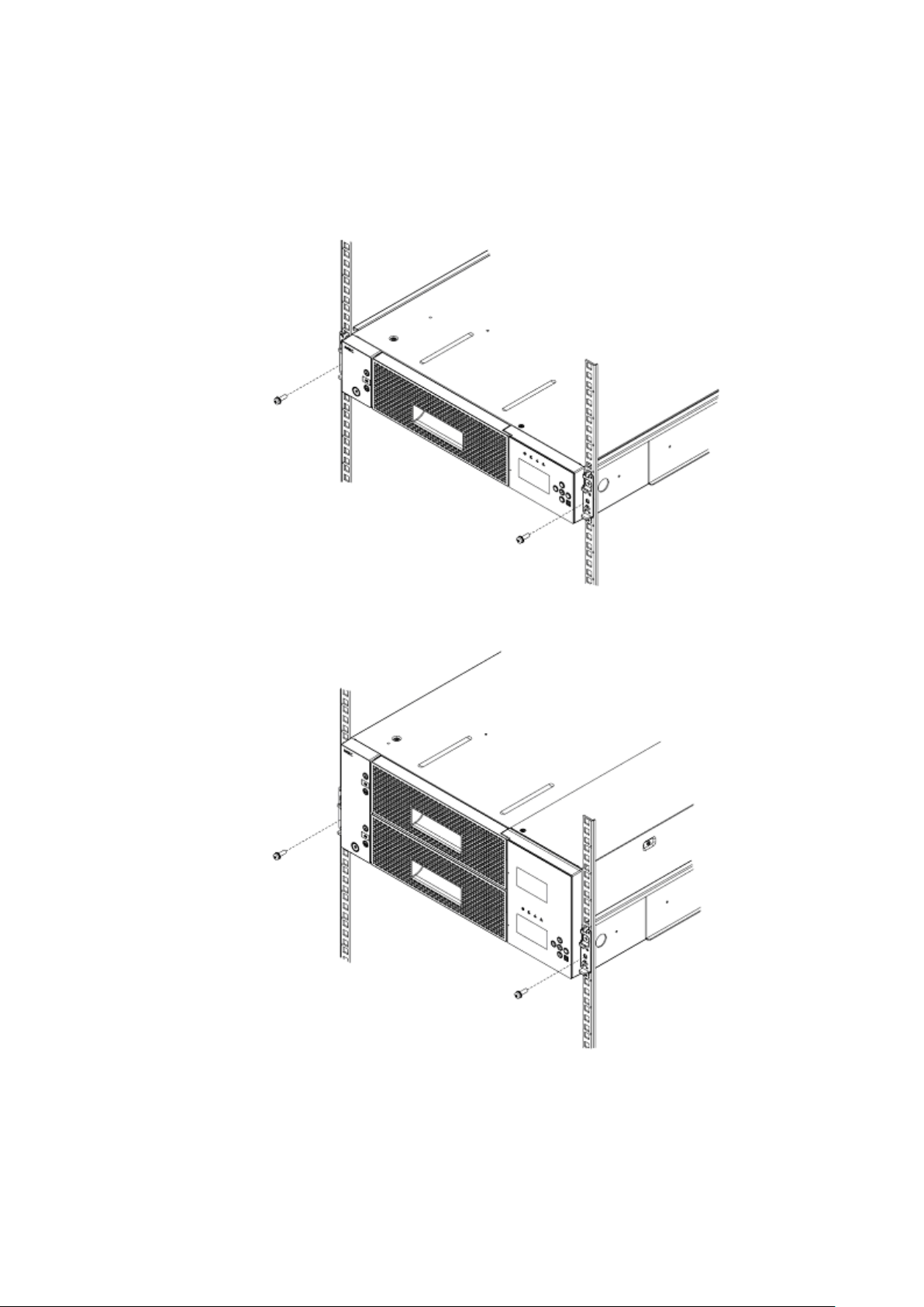
T30A
T60A
Use two screws (M5) to attach the left and right of the Library's front side.
Figure 1-15 attachment of rack ears
-23-
Page 51

T30A
T60A
1.7.7 Attachment of Rack ear
Attach the left and right rack ears to the left and right of the Library's front side.
Figure 1-16 Fastening of Library’s front side
-24-
Page 52

1.7.8 Attachment of label plate
Attach the label plate with repetition belt to the left of library ‘s back side.
Figure 1-17 attachment of label plate
-25-
Page 53

Make sure that the shipment stabilizer screw has been unfastened.
If the power is turned on while the screw is still fastened, operation faults may
occur
If the error message "***CHK*** CODE:[0009]" is displayed, turn off the power and
unfasten
this shipment stabilizer screw before turning the power back on.
1.8 Removal of shipment Stabilizer
The Library has a screw that is fastened to its rear side to stabilize the internal Accessor during
shipment.
Before using the Library, be sure to unfasten this screw.
-26-
Page 54

After connecting the cable, make sure it is connected securely.
The SAS cable's connector includes a locking mechanism.
Make sure it is set to the locked position.
Please connect it from the connector of a lower number sequentially when you connect
divergence SAS cable.
Chapter2 Setup
This chapter describes the cable connections, diagnostic test, and operation checks, which are all needed to
set up the library.
* If setup is not necessary, go to "Chapter4Operator Panel" or "Chapter5Remote Manager Interface Remote
Management Interface."
2.1 Connection of a Interface Cable
This section describes how to connect the product to a server or switch by using an interface cable.
The T60A library can house up to four drives, and the T30A library can house up to two drives.
2.1.1 Connection of SAS Cable
Connect each SAS drive of the library to a server by using an SAS cable. The product has an SAS
connector on the back.Be sure to connect the SAS cable to Port A of each drive.
Make sure that the cable is plugged all the way in.
(* The product will not work if the cable is connected to Port B.)
-27-
Page 55

After connecting the cable, make sure it is connected securely.
The FC cable's connector includes a locking mechanism.
Make sure it is set to the locked position.
2.1.2 Connection of FC Cable
Connect the FC drive of the product to a server or switch by using an FC cable. The product has
an FC connector on the back. Be sure to connect the FC cable to Port A. Before connecting the
cable, remove the white protection caps.
(* The product will not work if the cable is connected to Port B.)
(Connector on the upper side of the drive; shown on the right is the connector with the caps
removed.)
For information about how to connect a server or switch, see the manual accompanying the server
or switch.
-28-
Page 56

When a wrong topology, Loop ID, and Link Speed are set, the entire system might be
negatively affected.
・Please set it to the loop when connecting directly with HBA.
・Please set it to Point to Point when you pass the FC switch.
Setting item
procedure
1.Setting of library and drive
(1) Setting of Fibre Channel or SAS
(2) Setting of drive port / media changer path
(3) Setting of I/O Station
(4) Setting of slots
4.5.3.1 or 4.5.3.2
4.5.3.3
4.5.5
4.5.6
2.Setting of Network
(1) Setting of IP address
(2) Setting of subnetmask
(3) Setting of gateway
(4) Setting of DHCP
5.2
5.2
5.2
5.2
3.Setting of Time
4.4.2.5 or 5.6.5.5
2.2 Connection of AC Power Cable
After connecting the signal cable, insert the AC power cable's plug into the Library's AC power
connector. Make sure that the plug is fully inserted.
When the redundant power supply is installed in the library, insert the AC power cable’s plug into
each Library’s AC connector.
2.3 Power-On and self test
Turning on the power of the unit starts power-on sequence automatically.
For description of power-on, see “3.1Power-On and Power-On Sequence”.
2.4 Setting Drive configuration
Set the interface configuration in the drive module referring the panel operation in
4.4.2Configuration.
[SAS interface]
・Drive Path The setting of drive path
・Media Changer Path The setting of the media changer path of the robot
・Link Speed 3Gbps、6Gbps
・Power Save Mode The setting of drive power save mode
[FC interface]
・Control Path The setting of drive path
・Media Changer Path The setting of the media changer path of the robot
・Topology Point to Point / loop
・Loop ID 0 to 125
・Link Speed Auto、1Gbps、2Gbps、4Gbps、8Gbps
・Power Save Mode The setting of drive power save mode
2.5 Setting Library and Drive configuration
After the library starts normally, the composition of the library and the drive can be set.
Table 2-1 Setting item
Since time information is reset (2000/1/1/00:00:00) when the state of the equipment power supply
OFF continues, please carry out a time setup again after the power supply ON.
-29-
Page 57

2.6 Diagnostic Test
Load the diagnostic cartridge in the library, and execute the diagnostic test. For information about
how to perform this test, see "9.2Diagnosis test."
2.7 Operation Checks after Installation
After installing and setting up the library, connecting the cables, executing the diagnostic test, and
loading the cartridges, check the following:
1. Check that all the cables are connected properly to the connectors.
2. Check that there are no unnecessary items, such as components, connectors, or tools, left in the
library.
3. Check that the magazines are mounted.
4. It is confirmed whether the time displayed in the library is correct. (If time shifts, a set change is
done. Please refer to 4.4.2.5 or 5.6.5.5 )
After checking the library, perform a connection check from the server.
If you can recognize the library from the server, perform an online check using backup software. If
the library is offline, change the relevant setting to make it online or check the setting of the server.
For information about how to perform a check by using the backup software, refer to the manual of the
backup software.
-30-
Page 58

If a cartridge is loaded into the drive before the system is started, errors may occur
when reading or writing data stored in the cartridge.
When shutting down the system, use your backup application or check for messages on
the LCD to make sure that no cartridges have been loaded into the cartridge drive. If
the system is shut down while a cartridge is loaded in the cartridge drive, the next time
the system is started errors may occur when reading or writing data stored in the
cartridge, which can lead to malfunctions in the cartridge or the Library.
Do not shut down and restart the system while the Library is operating. Make sure that
the LIbrary has stopped before shutting down the system or restarting it.
Chapter3 Power-On and Power-Off
3.1 Power-On and Power-On Sequence
Turning on the power of the product initiates a self test. The self test takes several minutes, but no
other operation can be performed during the test.
Before turning on the power, check that the fastening screw for transportation has been
removed (see "1.8Removal of shipment Stabilizer").
3.2 Starting the System
When starting the system, first start the LIbrary (and any peripheral devices connected to the server or
workstation), then turn the server or workstation's power on to start the system.
1) Push the power switch button located on the front of the unit to turn on the power.
2) When the power is supplied, [Power LED] goes on green and the system starts power-on test.
3) When the power-on test successfully completed, a [Ready] appears on the operator panel.
3.3 Shutting Down the System
When shutting down the system, first turn off the power to the server or workstation, then the power to
the Library (and any peripheral devices connected to the server or workstation) to shut down the system.
3.4 Power-Off and Power-Off Sequence
1) Push the power switch button (for about 1sec) located on the front of the unit to turn off the power.
2) The shutdown processing is begun, and the power supply is turned off automatically.
When the data cartridge is stored in the drive, power supply OFF is not carried out automatically.
After choosing [NO],take out a data cartridge from a drive and carry out power supply OFF again, or
choose [Yes], and turn off a power supply as it is.
However, if power supply OFF is carried out where a data cartridge is stored in a drive, it will become
a cause of failure of a data cartridge and this equipment.
In moving of Library, turn off the power supply of library(see “9.8Moving the Library”)
-31-
Page 59

1.Menu title
2.Menu item
Chapter4 Operator Panel
This chapter describes how to use the operation panel and how to enter settings for the Library and the
cartridge drive.
Settings can be entered for the Accessor and the drive only after the Library has been reset.
4.1 Panel Indications
The library unit has three screens. The [Menu screen] is used for operation and setting of library unit.
The [Status Display screen] is for real-time display of the internal state of library unit. The
[Asynchronization message screen] display the message to draw attention to the operator. Described
below is detailed explanation of [Menu screen], [Status Display screen] and [Asynchronization message
screen].
4.1.1 Menu Screen
[Menu screen] appears when a user attempts to operate the library unit or configure it. The following
items are displayed.
Figure 4-1 Menu Screen
1.Menu title
Indicates the menu title currently displayed.
2.Menu item
Indicates the menu item. See "4.2Menu Tree" for details.
-32-
Page 60

(1)
(2)
(4)
(5)
(6)
(8)
(7)
(3)
(9)
4.1.2 Status Display screen
[Status Display screen] changes its display when no button operation is performed within certain
period of time on [Menu screen], or when Cancel button is pressed on [TopMenu] menu.
Shown below is the [Status Display screen]. The [Status Display screen] has the [Library State] that
displays a status of library and [Drive State] that displays a status of drive.
Each screen can be switched by pressing buttons other than Enter.
4.1.2.1 Library State
In this example, library state that installed four half-Height drives is displayed.
Figure 4-2 Component of Operator Panel
Library State is composed of the following.
1.Library status display
The following terms are used to indicate the status of the library.
-33-
Page 61

Message
Description
PLEASE INSERT MAGAZINE
Magazine insertion is requested.
MAGAZINE UNLOCKED
Magazine is not locked.
PLEASE CLOSE I/O STATION
I/O Station CLOSE is requested.
INITIALIZING・・・
Initialization is in progress.
INVENTORY・・・
Inventory is in progress.
SETTING・・・
Setting in progress
** CHK **
[XXXX]
Library error status (xxxx is the CHK code)
RECOVERING・・・
PLEASE WAIT
Library firmware is in recovery.
LIBRARY FIRMWARE
UPDATING!
Library firmware update is in progress.
DRIVEn FIRMWARE
UPDATING!
Drive firmware update is in progress.
DRIVE DUMP DATA
UPLOADING!
Dump data is being uploaded from drive.
EXCHANGE SLOTFULL
A cartridge is stored in the exchange slot.
CARTRIDGE WRONG
INSERTION
A cartridge has been incorrectly inserted in the drive.
ENDURANCE
COUNT OVER
The number of Accessor mechanism operations has reached
the expected life (endurance) value
OFFLINE
Library Offline(Not Ready)
CLEANING...
During drive cleaning
(This status message is displayed in doing “Clean Drive”)
REPLACE CLEANING MEDIA
Replacement of cleaning cartridge
CLEAN DRIVEn
Drive n cleaning is requested
PSU n FAULT
Power module error
PSU n FAN ERROR
Power module fan error
REDUNDANT PSU ERROR
Redundant power module error
Drive n FAN ERROR
Drive FAN error
READY
Ready(Idle)
(With no cartridge tape)
(with cartridge tape)
Table 4-1 Library Status displayed in the Operation Panel
2. Accessor status display section
Indicates whether a cartridge tape exists in the picker section of the accessor.
Figure 4-3 Accessor Icon
-34-
Page 62

I/O Station Disable
I/O Station Enable
Upper Magazine
Lower Magazine
rear
front
18slot Magazine
12slot Magazine
Upper
Center
Lower
3.Magazine status display section
Indicates the status of magazines on the library unit.
Figure 4-4 Magazine Icon
When the magazine is Opened, the display changes as shown below.
(In this example,Lower Magazine is Opened.)
Figure 4-5 Magazine Icon(Magazine is Opened)
When I/O Station is set, it is displayed as follows.
Figure 4-6 Magazine Icon(I/O Station is set)
When the I/O Station is Opened, the display changes as shown below. ([!] mark is displayed)
Cartridge existence information other than I/O Station are maintained.
-35-
Page 63

Indicates that no cartridge tape is inserted into
the escape slot.
Indicates that a cartridge tape is inserted into
the escape slot.
Indicates that no cartridge tape is inserted into
the tape drive.
Indicates that a cartridge tape is inserted into
the tape drive.
Indicates that the cartridge tape was ejected
from the tape drive.
Indicates that the tape drive detected error.
Indicates that the tape drive initializes.
Data slot
I/O Station
Figure 4-7 Magazine Icon (I/O Station is opened)
Graphic changes into each slot in the magazine depending on the number of cartridge storage as
follows. Moreover, a blink indication of the cartridge which the media error generated is given.
Figure 4-8 Magazine Icon(Slot Image)
4. Drive Icon
Indicates the status of tape drive installed in the library unit.
Table 4-2 Drive Status Icons
5. Library mode Icon
Indicates current Library mode setting(random / sequential / auto / system) of the library unit.
6. Prevent Icon
Indicates the prevent status of the library unit. When this icon is displayed, it is shown that it is a
state of Prevent.
7. Encryption Icon
Indicates whether the Encryption function of the library is effective.When this icon is displayed, the
library shows that the Encryption function is effective.
8. Display mode Icon
Indicated current mode of [Status Display screen]. (LIBRARY STATE / DRIVE STATE)
9. Media Changer Path Icon
Indicates on the drive specified as Media Changer Path.
-36-
Page 64

Indicates that no cartridge tape is inserted into the tape drive.
Indicates that a cartridge tape is inserted into the tape drive.
Indicates that the cartridge tape was ejected from the tape drive.
Message
Description
Ready
Indicates that a cartridge tape is inserted into the tape drive.
Not Ready
Indicates that the tape drive is initialing.
Empty
Indicates that no cartridge tape is inserted into the tape drive.
Ejected
Indicates that the cartridge tape was ejected from the tape drive.
Loading
Indicates that the tape drive is loading a cartridge tape.
Unloading
Indicates that the cartridge tape is unloading from the tape drive.
Rewinding
Indicates that the tape drive is rewinding a cartridge tape.
Cleaning
Indicates that the cleaning cartridge is cleaning the tape drive.
Reading
Indicates that the tape drive is reading data out from the cartridge tape.
Writing
Indicates that the tape drive is writing data into the cartridge tape.
Locating
Indicates that the tape drive is locating a cartridge tape.
Erasing
Indicates that the tape drive is erasing data into the cartridge tape.
Formatting
Indicates that the tape drive is formatting a cartridge tape.
Calibrating
Indicates that the tape drive is calibrating.
Offline
Indicates that the tape drive is offline.
Other
Other
(1)
(2)
(3)
(4)
(8)
(5)
(6)
(7)
4.1.2.2 Drive State
In this example, library state that installed four half-Height drives is displayed.
Drive State is composed of the following.
1. Drive Icon
Indicates the status of tape drive installed in the library unit.
Indicates whether a cartridge tape exists in the drive.
Table 4-3 Drive Status Icons
2. Drive message
Indicates the status of tape drive installed in the library unit.
The following terms are used to indicate the status of the drive.
Table 4-4 Drive Message
-37-
Page 65

3. Display mode Icon
Indicates the current mode of [Status Display screen]. (LIBRARY STATE / DRIVE STATE)
4. Prevent Icon
Indicates the prevent status of the drive. When this icon is displayed, it is shown that it is a state of
Prevent.
5. Fan Error Icon
Indicates the fan error status of drive.
6. Encryption mode Icon
Indicates whether an encryption setup of a drive is effective.
7. Compressed mode Icon
Indicates whether the data compression setup of a drive is effective
8. Drive Error Icon
Indicates the error code when drive error occurs.(See “B-3”)
-38-
Page 66

Asynchoronization
Message
Description
I/O Station is
being opened
Unlocking of I/O Station
Indication: Demanded the I/O Station lock release from the main management task
Message off:End of lock release
I/O Station is
opened
Unlocked of I/O Station
Indication: End of lock release
Message off:In five seconds or pressing some key
I/O Station open
failed
Unlocking of I/O Station failed CHK status
Indication: Abnormal termination of lock release of I/O station
Message off:Pressing some key
Magazine is being
unlocked(T30A)
Unlocking of Magazine
Indication: Demanded the Magazine lock release from the main management task
Message off: End of lock release
Upper Magazine
is being
unlocked(T60A)
Unlocking of Upper Magazine
Indication: Demanded the Magazine lock release from the main management task
Message off: End of lock release
Lower Magazine
is being
unlocked (T60A)
Unlocking of Lower Magazine
Indication: Demanding the Magazine lock release from the main management task
Message off: End of lock release
Magazine
is unlocked(T30A)
Unlocked of Magazine
Indication: End of lock release
Message off:Opening the Magazine or in 60 seconds without opening the magazine
Upper Magazine
is unlocked(T60A)
Unlocked of Upper Magazine
Indication: End of lock release
Message off:Opening the Magazine or in 60 seconds without opening the magazine
Lower Magazine
is unlocked(T60A)
Unlocked of Lower Magazine
Indication: End of lock release
Message off:Opening the Magazine or in 60 seconds without opening the magazine
Magazine unlock
failed
Unlocking of Magazine failed CHK status
Indication: Abnormal termination of lock release of Magazine
Message off:Pressing some key
Library Firmware
update in progress
Updating Library Firmware
Indication:Demanded display from each task
Message off: Demanded message-off from each task
Drive Microcode
update in progress
Updating Drive Firmware
Indication:Demanded display from each task
Message off: Demanded message-off from each task
Library Dump
upload in progress
Uploading Library Dump
Indication:Demanded display from each task
Message off: Demanded message-off from each task
Drive Dump upload
in progress
Updating Drive Dump
Indication:Demanded display from each task
Message off: Demanded message-off from each task
Other
Depending on the task of demanding.
Indication:Demanded display from each task
Message off: Demanded message-off from each task
4.1.3 Asynchronization message screen
[Asynchronization message screen] is indicated from [Menu screen] and [Status Display screen] by
priority.
There are two kinds (the message to disappear automatically when time passes to some degree and
the message to disappear when the operator intervenes it) in this message.
Table 4-5 Asynchronization Message
-39-
Page 67

Top Menu
Submenu
Commands
Move Cartridge
Unload
Clean Drive
Shipping Move
Reboot Drive
Reboot Library
Library State
Online / Offline
Drive State
Selecting of drive
Online / Offline
Warning Clear
4.2 Menu Tree
Table 4-6 Menu tree of commands
-40-
Page 68

Top Menu
Submenu
Configuration
Library Settings
I/O station
Enable / Disable
Active Slots
Auto Cleaning Mode
Enable / Disable
Library Mode
Random Mode
Sequential Mode
Loop Mode
Enable / Disable
Autoload Mode
Enable / Disable
Cleaning Notice
Near Expired
Enable / Disable
Every Cleaning
Enable / Disable
Apply
Network Settings
Link Speed
Auto Negotiation / 10Base-T Full / 10Base-T
Half / 100Base-TX Full / 100Base-TX Half /
1000Base-T Full / 1000Base-T Half
Protocol Stack
IPv4 / IPv6
IPv4 Settings
DHCP IPv4
Enable / Disable
IP Address
Subnet Mask
Gateway
Apply
IPv6 Settings
Stateless DHCP
Enable / Disable
DHCP IPv6
Enable / Disable
IP Address
Prefix Length
Gateway
Apply
Apply
Drive Settings
Selection of drive
Port A
Drive Path
Enable / Disable
Link Speed
(SAS)
3Gbps / 6Gbps
Topology
Loop / Point to Point
Set Loop ID
Link Speed
(FC)
Auto Negotiation /
8Gbps / 4Gbps / 2Gbps
/ 1Gbps
Port B
Port A
Media Changer Path
Enable / Disable
Power Save Mode
Enable / Disable
Apply
OP Panel Settings
Auto Backlight OFF
Enable / Disable
Login Mode
Enable / Disable
Auto Logout Mode
Enable / Disable
Change Password
Date / Time
Set Date
Set Time
Time Zone
Set Default
Table 4-7 Menu tree of configuration
-41-
Page 69

Top Menu
Submenu
Current Information
Setting Information
Library Setting
Network Settings
Drive Settings
OP Panel Settings
Slot Information
T30A
View Magazine
View Drive
View Escape Slot
View Accessor
T60A
View Upper Magazine
View Lower Magazine
View Drive
View Escape Slot
View Accessor
Table 4-8 Menu tree of current information
-42-
Page 70

Top Menu
Submenu
Service
View Error Status
View Library Error
View Drive Error
Diagnostics
Library Verify
Drive Diagnostics
Perform R/W Test
Media Test
Head Test
Statistics
View Accessor Data
View Retry Data
View Error Data
Clear Accessor Data
Clear Retry Data
Clear Error Data
Telnet Service Port
(only service login)
Enable / Disable
View Revision
Drive Replacement
(only service login)
Advanced Services
(only service login)
Mechanism Test
Demo(Slot-Drv-Slot)
Demo(Slot-Slot)
MSBF Test
X-Move Test
Y-Move Test
Pick/Put Test
Pick/Put/Move Test
Vibration Test
MAG Endurance Test
I/O Endurance Test
LCD/LED Test
Phy Test
Normal Operation
Test Mode 1
Test Mode 2
Test Mode 3
Test Mode 4
Library Log
Advanced Settings
Top Menu
Submenu
Logout
Table 4-9 Menu tree of Service
Table 4-10 Menu tree of logout
When the Login Mode setting is invalid, the item of Logout is not displayed.
-43-
Page 71

4.3 Login
Login is required before removing the Library's magazine, entering settings, or using the operation
panel's functions.
1) After the library unit is powered on and diagnosis of accessor starts.
2) Diagnosis of accessor is completed, the menu screen as shown below appears.
3) Enter the password on this menu screen.
Enter the user password consisting of four-digit number (from 0 to 9).
The factory-set user password is set as "0000".
4) If the password entered does not match the one stored in the library unit, the following message
is displayed. If this message is displayed, repeat steps from 3). Retry for password entry is not
limited.
5) When the correct password is entered, the [TopMenu] is displayed, and the library unit becomes
ready to operate. For menu screen, see ” 4.1.1Menu Screen”.
When the Auto Login setting is effective, this screen changes to "Top Menu" at once without
being displayed. When Login has succeeded, the Login screen is not displayed as long as it
doesn't Logout or automatic operation Logout do.
-44-
Page 72

【Service Login in “Login Mode Disable”】
Push the right-and-left button of an operator panel for 10 seconds.
It changes to a login screen compulsorily.
At the time of service login, the "S" icon which shows service
login is displayed on the upper left.
4.3.1 Service Login
Input with the password entry screen, "3776". It is displayed as the password error.
Service login can be done when inputting once after it returns to the screen of three, "2355".
-45-
Page 73

4.4 Top Menu
After Log in, the following screen is displayed.
Figure 4-9 Root screen of Top Menu
-46-
Page 74

Submenu item
Default
Description
Move Cartridge
-
Use this menu to move a cartridge in a slot to another slot of
the library.
Specify the slot type and slot numbers of source and
destination slots.
Unload
-
Use this menu to unload the cartridge from the drive.
In addition, it is necessary to execute Move Cartridge to return
it to the slot.
Clean Drive
-
Use this menu to provide cleaning on the drive.
Cleaning cartridge must be loaded beforehand.
See Section 4.8.1 for details.
Shipping Move
-
To carry the library, moves the robot to the carriage position.
Note: Take all the cartridges out from the magazine before
running this command. Before carrying the library, always run
this command.
After executing this command, be sure to fasten the Accessor
using the stabilizer screw.
Reboot Drive
-
This reboots the drive.
See Section4.10 for details.
Reboot Library
-
This reboots the Library.
Library State
■Online
□Offline
Online
This submenu can be used to switch the Library state between
online and offline.
See Section 4.5.4 for details.
Drive State
Online
This submenu can be used to switch the Drive state between
online and offline.
Warning Clear
-
When turning it off when the lighting Alarm indicator is
recovered from the error situation, it selects it.
4.4.1 Commands
Use the COMMANDS menu when moving the cartridge in the library or cleaning the drive through
operator panel.
Table 4-11 Commands Submenus
-47-
Page 75

Submenu item
Description
Library Settings
This submenu can be used to enter various Library settings.
Network Settings
This submenu can be used to enter various network-related settings.
Drive Settings
This submenu can be used to enter various drive settings.
OP Panel Settings
This submenu can be used to enter various settings on the operation panel.
Date/Time
This submenu can be used to set date and time.
Set Default
This submenu can be used to reset Library settings to their factory presets.
Do not use this submenu unless initializing the Library's settings.
4.4.2 Configuration
This menu is used to enter settings for the Library and the drive.
Table 4-12 Configuration Submenus
-48-
Page 76

Submenu item
Default
Description
I/O Station
Disable
Enable or disable the I/O station.
Active Slots
T30A:30
T60A:60
Sets the number of data slots and the active/inactive setting.
Each logical library can be set.
Auto Cleaning Mode
Disable
Enable or disable auto cleaning.
Each logical library can be set.
For auto cleaning to be executed, an Inactive slot must be set
in advance.
Library Mode
Random Mode
This submenu can be used to switch between random and
sequential mode.
Sequential mode should be set when used in environments in
which the Accessor cannot be controlled.
・Random Mode
Random mode should be set when using backup software.
Sequential Mode
-Loop Mode
Operation does not stop after the cartridge has been unloaded
by the host from the last slot. Instead, the first slot's cartridge
is loaded, and then operation continues.
-Auto Load Mode
When the magazine is set to the Library, the cartridge is
automatically mounted in the drive.
Cleaning Notice
-
This submenu can be used to setup the SNMP about
Cleaning.
・Nearly Expired
Nearly Expired trap is reported from setup value to 1.
Setup value:1-49
・Every Cleaning
Set up whether it remains for every cleaning execution
and report the number of times trap.
Apply
-
The above-mentioned setting is applied.
Auto Cleaning Mode:
When you use the library with backup software, please set up an Auto Cleaning
Mode Disable.
If the backup software supports the AUTO CLEANING Mode, use the auto
cleaning function of backup software.
4.4.2.1 Library Settings
Table 4-13 Library Setting Submenu
-49-
Page 77

Submenu item
Default
Description
Link Speed
Auto Negotiation
This sets the network's communications mode.
To use the auto setting, select "AUTO".
Protocol Stack
IPv4 Only
Setting of Protocol Stack
IPv4 Setting
-
Setting of IPv4 network
IPv6 Setting
-
Setting of IPv6 network
Submenu item
Default
Description
DHCP IPv4
Disable
This submenu can be used to configure the DHCP
server.
IP Address
192.168.1.1
This sets the IP address for access via a network.
Subnet Mask
255.255.255.0
This enables the Autoloader to be accessed from a
subnet.
Gateway
192.168.1.254
This indicates a gateway connection between subnets.
Apply
-
The above-mentioned setting is applied.
Submenu item
Default
Description
Stateless DHCP
Disable
This submenu can be used to configure the stateless
DHCP.
DHCP IPv6
Disable
This submenu can be used to configure the DHCP
server.
IP Address
0::0
This sets the IP address for access via a network.
Plefix length
64
This sets plefix length.
Gateway
0::0
This indicates a gateway connection between subnets.
Apply
-
The above-mentioned setting is applied.
4.4.2.2 Network Settings
Table 4-14 Network Setting Submenu
Table 4-15 IPv4 Setting Submenu
Table 4-16 IPv6 Setting Submenu
-50-
Page 78

Submenu item
Default
Description
Port-A
-
Setting of Port A of the selected drive.
Port-B
-
Setting of Port B of the selected drive.
A set content is the same as PortA. The license is
necessary for the setting.
Media changer path
Drive #1
Enable
Drive #2-#4
Disable
Set the drive that controls the library.
Apply
-
The above-mentioned setting is applied.
Submenu item
Default
Description
Drive path
Port –A:Enbale
Setting of port-A(Enable / Disable)
Link Speed
(SAS model.)
3Gbps
Link Speed:
Specify the drive max Link Speed,
”3Gbps”, “6Gbps” are selectable.
Topology
(It is non-display in
the SAS model.)
Point to point
Specify the topology type
Set Loop ID
(It is non-display in
the SAS model.)
000
Specify the three-digit number Loop ID.
Valid number range is 000-125.
Link Speed
(FC model.)
8Gbps
Link Speed: Specify the drive Link Speed, ”Auto”,
“1Gbps”, “2Gbps”, “4Gbps” or “8Gbps” are
selectable.
4.4.2.3 Drive Settings
Table 4-17 Drive Settings Submenu
Table 4-18 port setting submenu
-51-
Page 79

Submenu item
Default
Description
Auto Backlight OFF
Disable
This sets the panel's contrast.
・Enable
This sets the time until the LCD back light is
automatically shut off.
・Disable
This disables the LCD back light auto off
function.
Login mode
Enable
This submenu can be used to set login mode.
Auto Logout
Enable
This submenu can be used to set auto-logout.
・Enable
Sets Auto-Logout time.
Change Password
0000
This submenu can be used to change the login
password.
Submenu item
Default
Description
Set Date
2000/00/00
This submenu can be used to set the date.
Set Time
00:00:00
This submenu can be used to set the time.
Time Zone
+0:00
This submenu can be used to set the time zone.
4.4.2.4 OP Panel Settings
4.4.2.5 Date / Time
Table 4-19 OP Panel Settings Submenu
Table 4-20 Date / Time Submenu
4.4.2.6 Set Default
This menu can be used to reset the Autoloader's settings to its factory presets.
-52-
Page 80

Submenu item
Description
Setting Information
Use this menu to view the configuration of the library.
Slot Information
Use this menu to view the information of the cartridge stored in the
library.
Submenu item
Description
Library Settings
Partition / I/O station / Active Slots / Auto Cleaning / Library Mode /
Cleaning notice
Network Settings
link status / wwide node name / protocol stack / DHCP IPv4 / IP
Address IPv4 / subnet mask IPv4 / gateway IPv4 / stateless DHCP /
DHCP IPv6 / IP address IPv6 / Prifix Length / Gateway IPv6
Drive Settings
Port-A / Port-B / Media Changer / Power Save Mode
OP Panel Settings
Auto Backlight / Login Mode / Auto Logout
Date/Time Settings
Date/time/UTC
Submenu item
Description
View Upper Magazine
Displays the information of the cartridge stored in upper magazine.
View Lower Magazine
Displays the information of the cartridge stored in Lower magazine.
View Drive
Displays the information of the cartridge loaded in the drive.
View Accessor
Displays the information of the tape retained by the accessor.
View Escape Slot
Displays the information of the cartridge loaded in the escape slot.
4.4.3 Current Information
Current information about library, network, drives, cartridges in the library are displayed.
Table 4-21 Current Information submenu
4.4.3.1 Setting Information
This menu can be used to view the configuration of the library.
Table 4-22 Information to be displayed on Setting Information menu
4.4.3.2 Slot Information
This menu can be used this menu to view the information of the cartridge stored in the library.
Table 4-23 Information to be displayed on Slot Information menu
-53-
Page 81

Submenu item
Description
View Error Status
This checks the errors in Library or the drive.
Diagnostics
This diagnoses Library.
At least one data cartridge is needed to diagnose Library.
Statistics
This checks the statistics information in Library.
Telnet Service Port
This enables and disables the TELNET port.
View Revision
This checks the firmware revision information.
Drive Replacement
This menu is used in exchanging the drive.
Advanced services
This menu can be used to test of library.(only service login)
Library Log
This checks the library log.
Submenu item
Description
View Library Error
This checks the errors in Library.
View Drive Error
This checks the errors in the drive.
Submenu item
Description
Library Verify
This diagnoses Library.
Drive Diagnostics
This diagnoses the drive in Library.
・Perform R/W Test
・Media Test
・Head Test
At least one data cartridge is needed to diagnose.
The I/O station is unlocked when the diagnosis begins, and turn on the diagnosis
cartridge.
The I/O station is unlocked when the diagnosis ends, and exhaust the diagnosis cartridge.
When detecting it abnormally, an error code is shown to an operator panel, so please push
Enter button to advance check movement first after confirmation.
4.4.4 Service
This menu is used to check or test errors in the Library or drive.
4.4.4.1 View Error Status
Table 4-24 Service submenu
Table 4-25 Information to be displayed on View Error Status
4.4.4.2 Diagnostics
Table 4-26 Diagnostics
-54-
Page 82

Submenu item
Description
View Accessor Data
This checks the statistics information in the Accessor.
View Retry Data
This checks the statistics information in the Retry.
View Error Data
This checks the statistics information in the Error.
Clear Accessor Data
This clears the statistics information in the Accessor.
Clear Retry Data
This clears the statistics information in the Retry.
Clear Error Data
This clears the statistics information in the Error.
Submenu item
Description
Library
vendor ID / product ID / Serial No / FW rev / mac address
Drive
vendor ID / product ID / serial No / FW rev / wwnodename /
wwportname
Submenu item
Description
Selection of the drive
Remove Drive
This is used to remove drive.
Restore Drive
This is used to restore drive.
It is chosen whether a drive serial number is succeeded after Restore
Drive selection.
4.4.4.3 Statistics
This menu is used to check the statistics information in Library.
Table 4-27 Information to be displayed on Statistics
4.4.4.4 Telnet Service Port
This menu is used to enable and disable the TELNET port.
4.4.4.5 View Revision
This menu is used to check the firmware revision of the library and the installed drive.This menu is
used to check the firmware revision information of Library.
Table 4-28 Information to be displayed on View Revision
4.4.4.6 Drive Replacement
This menu is used to exchange the drive.
-55-
Page 83

Submenu item
Description
Mechanism test
The following mechanism test can be executed. (Do not use it usually. )
・Demo (Slot-Drv-Slot)
・Demo (Slot-Slot)
・MSBF Test
・X-Move Test
・Y-Move Test
・Pick/Put Test
・Pick/Put/Move Test
・Vibration Test
LCD / LED test
LCD / LED test can be executed. (Do not use it usually. )
Phy test
Ethernet phy test can be executed. (Do not use it usually. )
Submenu item
Description
Library Log
Error Log / Cleaning Log / Media Error Log
4.4.4.7 Advanced Service
This menu is used to test of Library. (Do not use it usually. )
4.4.4.8 Library Log
This menu is used to check the Library Log.
Table 4-29 Test to be displayed on Advanced Service
Table 4-30 Information to be displayed on View Revision
4.4.5 Logout
This returns to the Login menu.
-56-
Page 84

4.5 Configuring the Library
This section describes Library configuration,setting of the drive, changing of the password , and
setting for I/O station.
4.5.1 Viewing Configuration data of the library
Take the following steps to view the configuration data of the library.
1) [Login]. See Section 4.3Login for detail.
2) Select [Current Information].
3) Select [Setting Information] from [Current Information].
The configuration information of the library is displayed.
To view the firmware version of the library, select [View Revision] from [service] of [Top menu].
4.5.2 Change password
The following describes how to change the password used during login.
1) [Login]. See Section 4.3Login for detail.
2) Select [Configuration].
3) Select [OP Panel Settings] from [Configuration].
4) Select [Change Password] from [Configuration].
5) The following password input menu will appear.
Enter a new four-digit password.
6) Next, retype the password that you entered at step 5).
7) If the password entered in step 5) and 6) match, the following message will appear.
-57-
Page 85

Once the above message is displayed, the new password is valid.
If the entered passwords do not match, the following message will appear.
If the above message is displayed, start again from step 4).
-58-
Page 86

4.5.3 Setting of Drive
This section describes how to set configuration for tape drive installed in the unit.
1) [Login]. See Section 4.3Login for detail.
2) Select [Configuration].
3) Select [Drive Settings] from [Configuration].
4) Select the drive to set change.
5) Refer to 4.5.3.1at the SAS drive. Refer to 4.5.3.2 at the FC drive.
4.5.3.1 Setting of Serial Attached SCSI
This section describes how to set SAS(Serial Attached SCSI) interface configuration for tape drive
installed in the unit.In case of SAS drive, set drive path and robot control path.
Refer to 4.5.3.3 Setting robot control path in the setting of the robot control path.
1) The following screen will appear after selecting SAS drive.
1.Setting of drive path
1) Select either of Enable , Disable.
2) Selecting [Apply], the port of the drive is reset,and the setting is applied.
2.Setting of Link Speed
1) Specify the link speed from 3Gbps, 6Gbps.
2) Selecting [Apply], the port of the drive is reset,and the setting is applied.
-59-
Page 87

The valid value for Loop ID is in the range between 000 and 125.
Setting of Fibre Channel:
Selecting [Apply], the port of the drive is reset,and the setting is applied.
If [Apply] is selected after all of 1(Topology), 2(Loop ID) and 3(Link Speed) are set,
setting can be set by port reset only once.
4.5.3.2 Setting of Fibre Channel
This section describes how to set Fibre channel interface configuration for tape drive installed in the
unit. In case of FC drive, set drive path , topology , loop ID , Link Speed and robot control path.
1) The following screen will appear after selecting SAS drive.
1.Setting of drive path
1) Select either of Enable , Disable.
2) Selecting [Apply], the port of the drive is reset,and the setting is applied.
2.Setting of Topology
1) Select either of Loop , Point to Point.
2) Selecting [Apply], the port of the drive is reset,and the setting is applied.
3.Setting of Loop ID
1) Select [Set Loop ID].
2) Input three-digit number for Loop ID.
3) Selecting [Apply], the port of the drive is reset,and the setting is applied.
4.Setting of Link Speed
3) Specify the link speed from Auto Negotiation, 8Gbps, 4Gbps, 2Gbps, or 1Gbps.
4) Selecting [Apply], the port of the drive is reset,and the setting is applied.
-60-
Page 88

4.5.3.3 Setting robot control path
This section describes how to set robot control path.
1) [Login]. See Section 4.3Login for detail.
2) Select [Configuration].
3) Select [Drive Settings] from [Configuration].
4) Select the drive that sets the robot control passing.
5) Select Enable under Media Changer Path.
6) Selecting [Apply], the port of the drive is reset,and the setting is applied.
-61-
Page 89

Similar steps are used to switch from offline to online mode.
Because the port of the drive is closed when the library is switched to off-line, the
connection with the server is cut.
4.5.3.4 Power Save Mode
This section describes how to set Power Save Mode.
1) [Login]. See Section 4.3Login for detail.
2) Select [Configuration].
3) Select [Drive Settings] from [Configuration].
4) Select the drive that sets power save mode.
5) Select Enable under Power Save Mode.(Default:Enable)
6) Selecting [Enable], the screen which inputs time to shift to an energy conservation mode is
indicated. When time is input, confirmation screen is indicated. Setting is applied by [Yes].
4.5.4 Switching between ONLINE and OFFLINE
The Library usually starts in online mode. When operating the Library by itself, switch to offline
mode.
The following describes how to switch from online to offline mode.
1) [Login]. See Section 4.3Login for detail.
2) Select [Commands].
3) Select [Offline] under [Library State] from [Commands].
4) Select [Offline] and [Yes] to switch library to offline.
5) Library is switched to Offline
-62-
Page 90

If I/O Station is enabled:
If the I/O station is enabled, two decreases of the number of slots that can be set.
The number that can be set as Active Slots is only the even numbers.
4.5.5 Setting of I/O Station
You can configure the library unit to use a part of the front magazine as I/O station. Described
below is the setting procedure.
1) [Login]. See Section 4.3Login for detail.
2) Select [Configuration]
3) Select [Library Settings] from [Configuration].
4) Select [Enable] of [I/O station] from [Library Settings].
5) Selecting [Apply], the port of the drive is reset,and the setting is applied.
4.5.6 Setting of Active Slot
You can change the number of slots logically in the library unit. Described below is setting
procedure.
1) [Login]. See Section 4.3Login for detail.
2) Select [Configuration].
3) Select [Library Setting] from [Configuration].
4) Select [Active Slots] from [Library Settings].
5) The following screen will appear.
6) Input number of Active slots.Select [Yes] to set change number of Active slots.
7) Selecting [Apply], the port of the drive is reset,and the setting is applied.
-63-
Page 91

Release lever of fall prevention lock
Draw out the magazine by both hands.
4.6 Insertion and Removing Cartridge by Operator Panel
This section describes how to insert and remove the cartridge from the library by the operation of
the operator panel using the magazine and I/O station.
4.6.1 Magazine Operations
4.6.1.1 Removing Magazine
Magazine parts are composed of front magazine and rear magazine.
Described below is the procedure to remove front magazine.
1) [Login]. See Section 4.3Login for detail.
2) Put Magazine Unlock button.(refer to 1.3.3.2Button)
3) The message of [Magazine is unlocked] is displayed in Library state on LCD screen, and
magazine is unlocked. Next,draw out the magazine.
4) Draw out the magazine slowly until there is a locked feeling. Please do not draw out the
magazine strongly.
5) Draw out the magazine with pressing the lever under the left of the magazine.( Release lever of
fall prevention lock).
(Draw out the magazine by both hands.)
The front magazine can be removed above.
-64-
Page 92

release lever of fall prevention lock
Described below is the procedure to remove rear magazine.
The rear magazine is drawn out to the position of the following picture with drawing out the front
magazine.
6) A rear magazine is drawn out according to the procedure3),4) similar to the procedure for
drawing out the front magazine.(Refer to follwing picture about the location of release lever of
fall prevention lock)
Please do not draw out the magazine strongly.
-65-
Page 93

Insert the cartridges correctly. If a cartridge is inserted in the wrong direction or
it is not fully inserted into the slot, the Library may not start, an error message
may be displayed, and the Accessor or cartridge may be damaged.
4.6.1.2 Insertion of cartridges into magazine
When inserting cartridges into the slots of the magazine, note the direction of each cartridge. If a
cartridge is inserted in the wrong direction, malfunctions may occur. Refer to the photo below before
inserting.
For description of magazine slot numbers, see” 1.3.4.1Slot number”
4.6.1.3 Removal of cartridges from magazine
To remove a cartridge, slide the locking mechanism to the left located next to the slot's opening.
-66-
Page 94

This removal method should be used only during an emergency.
The point to remove upper magazine in the emergency
The point to remove lower magazine in the emergency
4.6.1.4 Emergency removal of magazine
When the magazine is taken out in case of things except the necessity by the following operations,
neither the library device operation, the drive device nor the tape cartridge can be guaranteed.
Moreover, please note that it causes the breakdown of the transportation device ([accessor]) and the
magazine when the tape cartridge is taken out while operating.
The steps for removing the magazine from the Library are described below.
1) Insert a pointed object (such as a small Philips screwdriver) into the round hole shown below.
2) Keep the object inserted while pulling out the magazine.
-67-
Page 95

The I/O station dashes out to a device front side after pressing the enter button. Please
there must not be danger from which the hand is placed between the moving part, and
do not affix the hand to the magazine, and do not put the finger in the opening of the
magazine until the I/O station dashes out. Please push the magazine a little when the
finger is placed in the opening of the magazine by any chance and pull out the finger
while returning it.
Insert the cartridges correctly. If a cartridge is inserted in the wrong direction or
it is not fully inserted into the slot, the Library may not start, an error message
may be displayed, and the Accessor or cartridge may be damaged.
Don’t lift the cover of the I/O station.
4.6.2 I/O Station Operations
1) [Login]. See Section 4.3Login for detail.
2) Push Magazine I/O station Unlock button.(refer to 1.3.3.2Button)
3) The message of [Push Enter Key] is displayed in Library state on LCD screen
4) Push Enter button , and I/O station is opened.
5) Refer to the photo below before inserting.
Prevented.
6) Close I/O station.
7) Inventory automatically starts.
The I/O Station lock release is not done when set from the host to the state of Media Removal
-68-
Page 96

4.7 Using the operation panel to move cartridges
4.7.1 Load cartridge into drive
The following describes how to use the operation panel to move a cartridge from a specified
magazine slot into the drive.
In this example, the cartridge in slot 1 will be loaded into the drive #1.
1) [Login]. See Section 4.3Login for detail.
2) Select [Commands].
3) Select [Move Cartridge] from [Commands].
4) The screen to specify the Source and Destination is displayed.
Figure 4-10 Move Cartidge
5) Select [slotxx] under [Source], and the slot where the cartridge is stored is displayed.
In this example, select slot01.
Figure 4-11 Select source Screen
-69-
Page 97

6) Select [slotxx] under [Destination], and the slot where the no cartridge is stored is displayed.
In this example, slect Drive1.
Figure 4-12 Select Destination Screen
7) Select [Execute], the cartridge is moved and inserted into the drive.
Figure 4-13 Select Execute
-70-
Page 98

This operation should be performed only during emergencies, such as when the
operation cannot be controlled from a host device.
4.7.2 Removing from the drive
The following describes the steps for moving a cartridge from the drive.
In this example, the cartridge in drive 1 will be removed into the slot1.
1) [Login]. See Section 4.3Login for detail.
2) If the library is in online state, set it to offline. See Section 4.5.4Switching between ONLINE
and OFFLINE for details.
Select [Unload] from [Commands] to eject a cartridge from the drive.
If you select [Unload], you are prompted to select the drive to unload. Specify the relevant
drive and execute the command. When [Unload] is executed, the cartridge moves to the drive
bay.
3) Select [Move Cartridge] from [Commands].
4) The screen to specify the Source and Destination is displayed.
Figure 4-14 Move Cartridge
5) Select [slotxx] under [Source], and the slot where the cartridge is stored is displayed.
In this example, select Drive1.
Figure 4-15 Select source screen
-71-
Page 99

6) Select [slotxx] under [Destination], and the slot where the no cartridge is stored is displayed.
In this example, slect Slot01.
Figure 4-16 Select Destination screen
7) Select [Execute], the cartridge is ejected from the drive and moved to the slot.
Figure 4-17 Select Execute
-72-
Page 100

・Use a special cleaning cartridge with a bar code label that supports the drive to be
cleaned.
・Clean the drive once a month or a backup of 100 hours when cleaning is necessary
in operation.(When there is a cleaning request from the drive, clean the drive.)
・Each cleaning cartridge can be used up to 50 times.
Record the number of use, and when 50 times is reached, replace the cleaning
cartridge.
The drive will not be cleaned even if the cleaning cartridge being used has
exceeded its service life. When it's detected that a cleaning cartridge reached its
service life, it's shown to an operator panel with "REPLACE CLEANING
MEDIA".
・[Clean Drive] doesn't operate when the bar code for the cleaning cartridge is not
stuck on the cleaning cartridge. In that case, please use and clean [Move
Cartridge].
・[Clean drive] should be performed only when there are no backup software jobs
being executed.
When you use the library with backup software, please set up an Auto Cleaning
Mode Disable.
If the backup software supports the AUTO CLEANING function, use the auto
cleaning function of backup software.
4.8 Cleaning
4.8.1 Cleaning by Operation panel
Before using the operation panel to set cleaning, make sure that the backup software will not be
executing any jobs during the cleaning process. (If necessary, take measures such as turning off the
backup software service.)
1) Check that the cleaning cartridge is appropriate to the target drive and its use count limitation
has not been reached.
2) [Login]. See Section 4.3Login for detail.
3) Remove the magazine, and set the cleaning cartridge into the slot.
4) Select [Clean Drive] from [Commands].
5) Select the target drive to be cleaned.
6) The drive automatically performs cleaning. When the cleaning is complete, the cleaning
cartridge is returned to the slot as before.
7) Remove the magazine, and then remove the cleaning cartridge.
4.8.2 Auto Cleaning
The auto cleaning function enables the Library to automatically clean drives that require cleaning.
Be sure to insert the cleaning cartridge into an Inactive slot.
When the auto cleaning function is on and the drive requests cleaning, the Accessor removes the
cleaning cartridge from the unused slot and loads it into the drive. When cleaning is finished, it returns
the cartridge to the same Inactive slot.
-73-
 Loading...