

Page 1

NEC Express5800/T120d
Configuration Guide
Introduction
This document contains product and configuration information that will enable you to configure your system. The
guide will ensure fast and proper configuration of your NEC Express5800 server.
October 25, 2013
Revision 5.0
NEC Corporation
Page 2

CONFIGURATION GUIDE – NEC Express5800/T120d
NEC Corporation Revision 7.0 – October 25, 2013 2
Contents
TECHNICAL SPECIFICATION ........................................................................................ 3
Key Features .......................................................................................................................................... 3
Specification .......................................................................................................................................... 3
EXTERNAL VIEWS ......................................................................................................... 7
Front and Rear Views ........................................................................................................................... 7
Dimensions (mm) .................................................................................................................................. 9
CONFIGURATION DIAGRAM ....................................................................................... 10
EXPANSION SLOTS ..................................................................................................... 10
SERVER CONFIGURATION ......................................................................................... 11
1 Base Models ................................................................................................................................. 11
2 Processors and Heat Sink .......................................................................................................... 11
3 Memory ......................................................................................................................................... 12
3.1 Memory Configuration ......................................................................................................... 12
4 Internal Hard Disk Drives ............................................................................................................ 15
4.1 RAID Configuration .............................................................................................................. 15
4.2 Hot Plug 2.5-inch Internal Drive Configuration .................................................................... 19
4.3 Hot Plug 3.5-inch Internal Drive Configuration .................................................................... 40
4.4 Non-hot Plug 3.5-inch Internal Drive Configuration ............................................................. 45
5 Optical Drive ................................................................................................................................. 47
6 Internal Tape / RDX Drives .......................................................................................................... 48
6.1 Tape / RDX Drive Selection ................................................................................................. 48
6.2 Tape / RDX Configuration .................................................................................................... 48
7 PCI Card ........................................................................................................................................ 50
7.1 Network Interface Controller ................................................................................................ 50
7.2 External Storage Controller ................................................................................................. 51
7.3 Serial Port Adapter .............................................................................................................. 52
8 Other Add-in Components .......................................................................................................... 52
8.1 Redundant Fan .................................................................................................................... 53
8.2 Trusted Platform Module Kit ................................................................................................ 53
8.3 Internal Flash Memory ......................................................................................................... 53
8.4 Flash FDD............................................................................................................................ 54
8.5 Input Devices ....................................................................................................................... 54
9 Add-on Components ................................................................................................................... 54
9.1 Server Management License............................................................................................... 54
9.2 Rack Conversion Kit ............................................................................................................ 54
9.1 Dust / Insect Proof Kit .......................................................................................................... 55
9.2 Medium and Cartridge ......................................................................................................... 55
REFERENCES............................................................................................................... 56
Server Management ............................................................................................................................ 56
OS Support Matrix for PCI Cards and Embedded Controllers ....................................................... 57
Supported PCI Cards and Installable Slots ...................................................................................... 57
Maximum power consumption .......................................................................................................... 59
Copyright Notice and Liability Disclaimer ........................................................................................ 60
REVISION HISTORY ..................................................................................................... 61
Page 3

CONFIGURATION GUIDE – NEC Express5800/T120d
NEC Corporation Revision 7.0 – October 25, 2013 3
Technical Specification
Key Features
High performance with the latest Intel® Xeon® processor E5-2400 product family
Up to 384 GB of high speed DDR3-1600 memory
High energy efficiency with power capping feature and 80 PLUS® Platinum or Gold power supply
Full manageability by integrated EXPRESSSCOPE Engine 3
Specification
(1/2)
Model
T120d
Processor
Type
Intel® Xeon®
Processor
E5-2403
Intel® Xeon®
Processor
E5-2407
Intel® Xeon®
Processor
E5-2420
Intel® Xeon®
Processor
E5-2430
Clock speed
1.80 GHz
2.20 GHz
1.90 GHz
2.20 GHz
Number of Processors
1 or 2
Cache
10 MB
15 MB
Cores and Threads
4C - 4T
6C - 12T
Chipset
Intel® C602 Chipset
Memory
Type
DDR3-1600 and DDR3-1066 ECC Registered Low Power DIMM
Standard Capacity
0 GB
Maximum Capacity
384 GB (12 x 32 GB)
Memory protection
ECC, x4 SDDC, Memory Mirroring, Memory Lockstep, Memory
Sparing
Internal Storage
Standard Capacity
0 GB
Maximum Capacity
Hot plug 2.5-inch drive configuration:
SAS HDD: 28.8 TB (24 x 1.2 TB)
SATA HDD: 24 TB (24 x 1 TB)
SAS SSD : 9.6 TB ( 24 x 400 GB)
Hot plug 3.5-inch drive configuration:
SATA HDD: 32 TB (8 x 4 TB)
Non-hot plug 3.5-inch drive configuration:
SATA HDD: 16 TB (4 x 4 TB)
Storage Controller
SATA : 3 / 6 Gb/s (Integrated)
SAS: 6Gb/s (Optional)
RAID
SATA : RAID 0/1/10 1 (Standard), RAID 5/6/50/60 (Optional)
SAS : RAID 0/1/5/6/10/50/60 (Optional)
Hot Plug
Supported with hot plug drive bay
Optical Disk Drive
Optional
5-inch Media Bays
2
Disk Drive Bays
Hot plug 2.5-inch drive configuration: 24
Hot plug 3.5-inch drive configuration: 8
Non-hot plug 3.5-inch drive configuration: 4
Expansion Slots
Total: 4 to 5 slots available
1 PCIe x16 Gen 3 (x16 connector)
1 to 2 PCIe x8 Gen 3 (x8 connector) 2
1 PCIe x4 Gen 2 (x8 connector)
1 PCIe x1 Gen 2 (x4 connector)
Page 4

CONFIGURATION GUIDE – NEC Express5800/T120d
NEC Corporation Revision 7.0 – October 25, 2013 4
Model
T120d
Video
Controller (VRAM)
Integrated in Server Management Controller (32MB)
Resolution / Color
1280 x 1024 / 16.7M 3
Interfaces
9 USB2.0 (2 x front, 4 x rear, 3 x internal)
1 VGA (15-pin mini D-sub, 1 x rear)
1 to 2 Serial (9-pin mini D-sub, RS232-C, 1 to 2 x rear)
2 1000BASE-T LAN connector (RJ-45, 2 x rear)
1 Management LAN connector (RJ-45, 1 x rear)
Server Management
EXPRESSSCOPE Engine 3
Redundant Fan
Optional, hot plug with redundant fan kit
Redundant Power Supply
Optional, hot plug with redundant power supply
Power Supply
2 x 450 / 800 Watt 80 PLUS® Platinum certified hot plug PSU
1 x 700 Watt 80 PLUS® Gold certified non-hot plug PSU
100-240 VAC ± 10% 50 / 60 Hz ± 3 Hz
Power
Consumption
(Max. Config, Idling)
289 VA /
287 Watt
293 VA /
291 Watt
297 VA /
295 Watt
296 VA /
295 Watt
(Max. Config,
Operating)
476 VA /
465 Watt
491 VA /
489 Watt
541 VA /
539 Watt
566 VA /
565 Watt
Acoustical Noise
(Sound Pressure
Level) 4
Max. Config, Idling
40.6 dB
Max. Config, Operating
44.3 dB
Dimensions (W x D x H )
200.0 x 599.0 x 438.0 mm / 7.8 x 23.5 x 17.2 in (5U)
Weight (Minimum / Maximum)
17 kg / 33.0 kg, 37.47 lbs. / 72.75 lbs.
Temperature, Relative Humidity
(non-condensing)
Operating: 10° to 40° C / 50° to 104° F, 20 to 80%
Non-Operating: -10° to 55° C / 14° to 131° F, 20 to 80%
Regulatory and Safety
FCC, C-TICK, CE, UL, CB, RoHS, WEEE
Operating Systems and Virtualization
Software
Microsoft® Windows Server® 2003 R2, Standard Edition
Microsoft® Windows Server® 2003 R2, Enterprise Edition
Microsoft® Windows Server® 2003 R2, Standard x64 Edition
Microsoft® Windows Server 2003 R2, Enterprise x64 Edition
Microsoft® Windows Server® 2008 Standard
Microsoft® Windows Server® 2008 Enterprise
Microsoft® Windows Server® 2008 Standard (x64)
Microsoft® Windows Server® 2008 Enterprise (x64)
Microsoft® Windows Server® 2008 R2 Standard
Microsoft® Windows Server® 2008 R2 Enterprise
Microsoft® Windows Server® 2012 Standard 5
Microsoft® Windows Server® 2012 Datacenter 5
Red Hat Enterprise Linux 5.7 or later (x86)
6
Red Hat Enterprise Linux 5.7 or later (EM64T)
6
Red Hat Enterprise Linux 6.2 or later (x86)
6
Red Hat Enterprise Linux 6.2 or later (x86_64)
6
VMware ESXi 4.1 Update 2
VMware ESXi 5 Update 1
VMware ESXi 5.1
VMware ESXi 5.5 7
1
Embedded SATA RAID controller is supported only on Windows operating systems.
2
One PCIe x8 Gen 3 slot is available in single processor system.
3
Maximum resolution available via EXPRESSSCOPE Engine 3 remote console is 1280 x 1024 / 65K colors.
4
Noise emission was measured at the operator positions in accordance with ISO 7779. The actual value may vary
by the operating environment.
5
For Windows Server 2012 installation, download the driver kit from the following website and install it after OS
installation
http://www.nec.com/en/global/prod/express/download/
6
For Linux support, contact our sales representative or go to the NEC website at:
Page 5

CONFIGURATION GUIDE – NEC Express5800/T120d
NEC Corporation Revision 7.0 – October 25, 2013 5
http://www.nec.com/en/global/prod/express/linux/index.html
7
Available in November 2013.
(2/2)
Model
T120d
Processor
Type
Intel® Xeon®
Processor
E5-2450
Intel® Xeon®
Processor
E5-2470
Clock speed
2.10 GHz
2.30 GHz
Number of Processors
1 or 2
Cache
20 MB
Cores and Threads
8C - 16T
Chipset
Intel® C602 Chipset
Memory
Type
DDR3-1600 and DDR3-1066 ECC Registered Low Power DIMM
Standard Capacity
0 GB
Maximum Capacity
384 GB (12 x 32 GB)
Memory protection
ECC, x4 SDDC, Memory Mirroring, Memory Lockstep, Memory
Sparing
Internal Storage
Standard Capacity
0 GB
Maximum Capacity
Hot plug 2.5-inch drive configuration:
SAS HDD: 28.8 TB (24 x 1.2 TB)
SATA HDD: 24 TB (24 x 1 TB)
SAS SSD : 9.6 TB ( 24 x 400 GB)
Hot plug 3.5-inch drive configuration:
SATA HDD: 32 TB (8 x 4 TB)
Non-hot plug 3.5-inch drive configuration:
SATA HDD: 16 TB (4 x 4 TB)
Storage Controller
SATA : 3 / 6 Gb/s (Integrated)
SAS: 6Gb/s (Optional)
RAID
SATA : RAID 0/1/10 1 (Standard), RAID 5/6/50/60 (Optional)
SAS : RAID 0/1/5/6/10/50/60 (Optional)
Hot Plug
Supported with hot plug drive bay
Optical Disk Drive
Optional
5-inch Media Bays
2
Disk Drive Bays
Hot plug 2.5-inch drive configuration: 24
Hot plug 3.5-inch drive configuration: 8
Non-hot plug 3.5-inch drive configuration: 4
Expansion Slots
Total: 4 to 5 slots available
1 PCIe x16 Gen 3 (x16 connector)
1 to 2 PCIe x8 Gen 3 (x8 connector) 2
1 PCIe x4 Gen 2 (x8 connector)
1 PCIe x1 Gen 2 (x4 connector)
Video
Controller (VRAM)
Integrated in Server Management Controller (32MB)
Resolution / Color
1280 x 1024 / 16.7M 3
Interfaces
9 USB2.0 (2 x front, 4 x rear, 3 x internal)
1 VGA (15-pin mini D-sub, 1 x rear)
1 to 2 Serial (9-pin mini D-sub, RS232-C, 1 to 2 x rear)
2 1000BASE-T LAN connector (RJ-45, 2 x rear)
1 Management LAN connector (RJ-45, 1 x rear)
Server Management
EXPRESSSCOPE Engine 3
Redundant Fan
Optional, hot plug with redundant fan kit
Page 6

CONFIGURATION GUIDE – NEC Express5800/T120d
NEC Corporation Revision 7.0 – October 25, 2013 6
Model
T120d
Redundant Power Supply
Optional, hot plug with redundant power supply
Power Supply
2 x 450 / 800 Watt 80 PLUS® Platinum certified hot plug PSU
1 x 700 Watt 80 PLUS® Gold certified non-hot plug PSU
100-240 VAC ± 10% 50 / 60 Hz ± 3 Hz
Power
Consumption
(Max. Config, Idling)
299 VA /
297 Watt
296 VA /
295 Watt
(Max. Config,
Operating)
614 VA /
613 Watt
657 VA /
656 Watt
Acoustical Noise
(Sound Pressure
Level) 4
Max. Config, Idling
40.6 dB
Max. Config, Operating
44.3 dB
Dimensions (W x D x H )
200.0 x 599.0 x 438.0 mm / 7.8 x 23.5 x 17.2 in (5U)
Weight (Minimum / Maximum)
17 kg / 33.0 kg, 37.47 lbs. / 72.75 lbs.
Temperature, Relative Humidity
(non-condensing)
Operating: 10° to 40° C / 50° to 104° F, 20 to 80%
Non-Operating: -10° to 55° C / 14° to 131° F, 20 to 80%
Regulatory and Safety
FCC, C-TICK, CE, UL, CB, RoHS, WEEE
Operating Systems and Virtualization
Software
Microsoft® Windows Server® 2003 R2, Standard Edition
Microsoft® Windows Server® 2003 R2, Enterprise Edition
Microsoft® Windows Server® 2003 R2, Standard x64 Edition
Microsoft® Windows Server 2003 R2, Enterprise x64 Edition
Microsoft® Windows Server® 2008 Standard
Microsoft® Windows Server® 2008 Enterprise
Microsoft® Windows Server® 2008 Standard (x64)
Microsoft® Windows Server® 2008 Enterprise (x64)
Microsoft® Windows Server® 2008 R2 Standard
Microsoft® Windows Server® 2008 R2 Enterprise
Microsoft® Windows Server® 2012 Standard 5
Microsoft® Windows Server® 2012 Datacenter 5
Red Hat Enterprise Linux 5.7 or later (x86)
6
Red Hat Enterprise Linux 5.7 or later (EM64T)
6
Red Hat Enterprise Linux 6.2 or later (x86)
6
Red Hat Enterprise Linux 6.2 or later (x86_64)
6
VMware ESXi 4.1 Update 2
VMware ESXi 5 Update 1
VMware ESXi 5.1
VMware ESXi 5.5 7
1
Embedded SATA RAID controller is supported only on Windows operating systems.
2
One PCIe x8 Gen 3 slot is available in single processor system.
3
Maximum resolution available via EXPRESSSCOPE Engine 3 remote console is 1280 x 1024 / 65K colors.
4
Noise emission was measured at the operator positions in accordance with ISO 7779. The actual value may vary
by the operating environment.
5
For Windows Server 2012 installation, download the driver kit from the following website and install it after OS
installation
http://www.nec.com/en/global/prod/express/download/
6
For Linux support, contact our sales representative or go to the NEC website at:
http://www.nec.com/en/global/prod/express/linux/index.html
7
Available in November 2013.
Page 7
CONFIGURATION GUIDE – NEC Express5800/T120d
NEC Corporation Revision 7.0 – October 25, 2013 7
External Views
Front and Rear Views
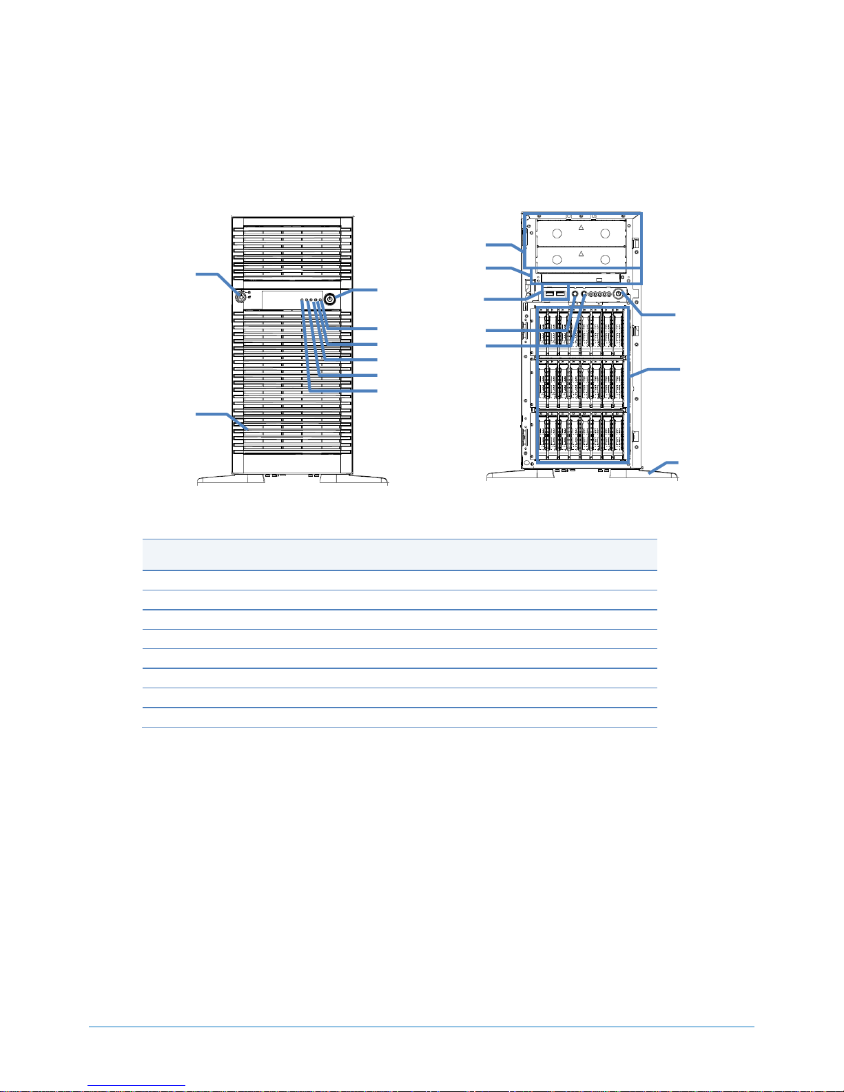
Front View
With Front bezel
Hot Plug 2.5-inch Drive Configuration
Legend
A.
Power Button
I.
5.25-inch Media Bay
B.
Power LED
J.
Optical Drive Bay
C.
Data LAN 1 Activity LED
K.
USB Connectors
D.
Data LAN 2 Activity LED
L.
Dump (NMI) Button
E.
Hard Drive Activity LED
M.
System Reset Button
F.
System Status LED
N.
Power Button
G.
Front Bezel
O.
2.5-inch Derive Bay
H.
Front Bezel Key
P.
Stabilizer
G
D
F
A E H
B
C
I
J
L
M
N
O K P
Page 8
CONFIGURATION GUIDE – NEC Express5800/T120d
NEC Corporation Revision 7.0 – October 25, 2013 8
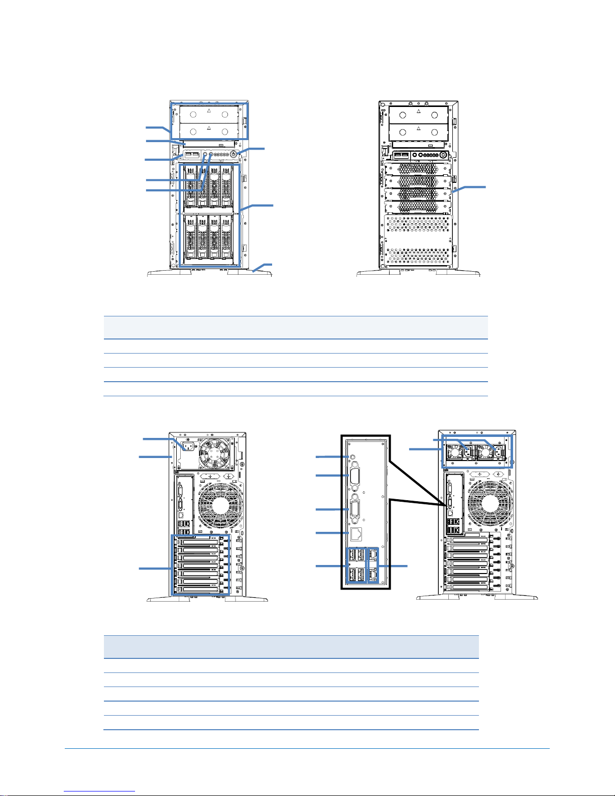
Front View
Hot Plug 3.5-inch Drive Configuration
Non-hot Plug 3.5-inch Drive Configuration
Legend
A.
5.25-inch Media Bay
E.
System Reset Button
B.
Optical Drive Bay
F.
Power Button
C.
USB Connectors
G.
3.5-inch Drive Bay
D.
Dump (NMI) Button
H.
Stabilizer
Rear View
Non-hot Plug Power Supply Configuration
Hot Plug Power Supply Configuration
Legend
A.
PCI Slots
F.
Management LAN Connector
B.
Power Supply Unit
G.
USB Connectors
C.
AC Inlet
H.
Data LAN Connectors
D.
Serial Port Connector
I.
BMC System Reset Button
E.
VGA Connector
F
A
B
C
D E G
H
G
A
B C D
E
F
G
H
I
C
B
Page 9

CONFIGURATION GUIDE – NEC Express5800/T120d
NEC Corporation Revision 7.0 – October 25, 2013 9
Dimensions (mm)
Non-hot Plug Power Supply Configuration
Hot Plug Power Supply Configuration
611.0
599.0
200.0
313.4
438.0
424.0
611.0
599.0
200.0
313.4
438.0
424.0
200.0
313.4
438.0
625.4
599.0
424.0
200.0
313.4
438.0
625.4
599.0
424.0
Page 10
CONFIGURATION GUIDE – NEC Express5800/T120d
NEC Corporation Revision 7.0 – October 25, 2013 10
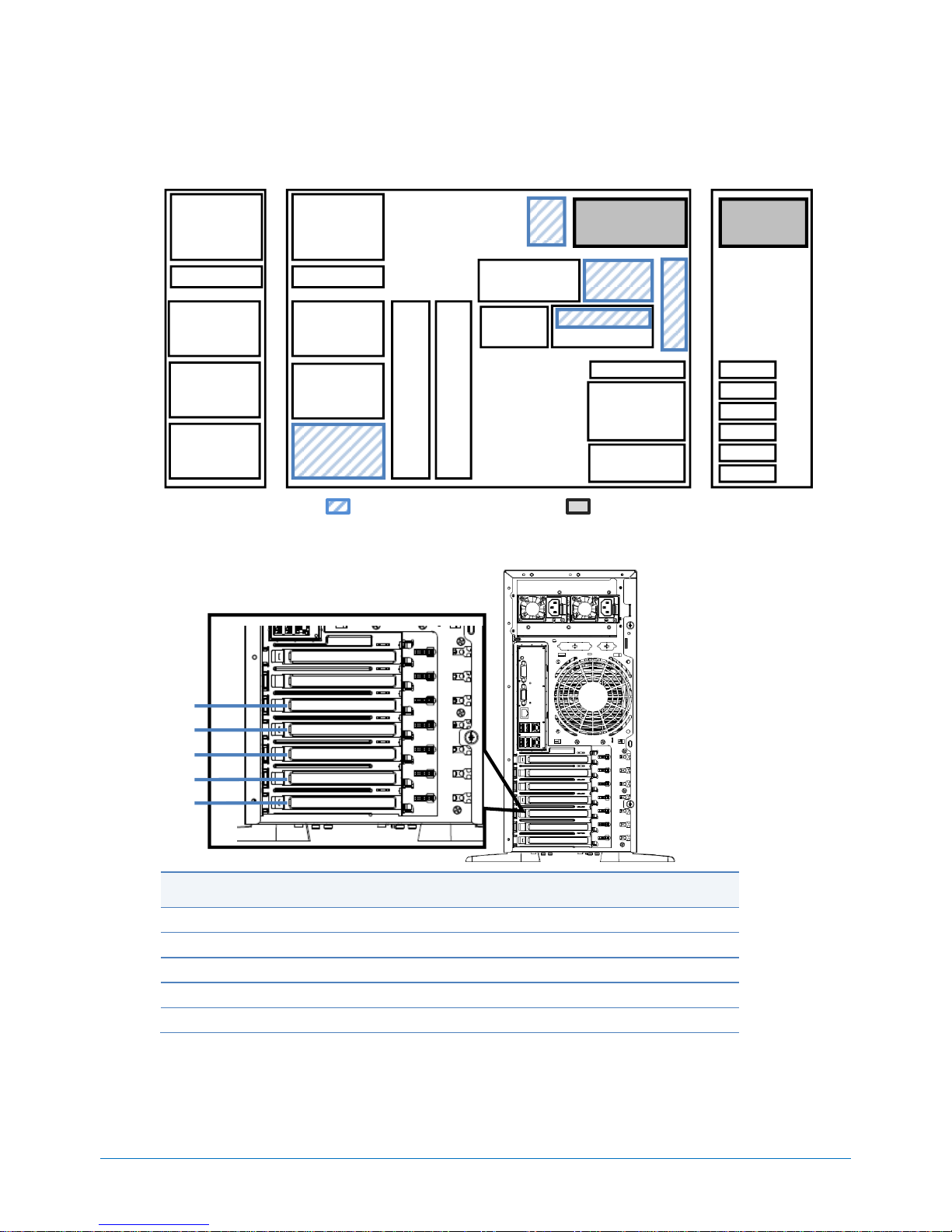
Configuration Diagram
Legend: Minimum required components Standard Components
Expansion Slots
Legend
#1
PCIe 3.0 x8, x8 connector, Full height, up to 300 mm length
#2
PCIe 3.0 x8, x8 connector, Full height, up to 300 mm length
#3
PCIe 3.0 x16, x16 connector, Full height, up to 300 mm length
#4
PCIe 2.0 x4, x8 connector, Full height, up to 300 mm length
#5
PCIe 2.0 x1, x4 connector, Full height, up to 300 mm length
NOTE:
The slot #1 is available in dual processor configuration.
CHASSIS
FRONT
CHASSIS
INSIDE
PCIe 3.0
PCIe 2.0
Cooling Fan
Processor
#2
Power Supply
PCI 5
Processor
#1
Optical Drive Bay
1 DIMM Slots
6 DIMM Slots
2 Media Bay
4 RAID BBU Slots
2 Media Bay
Optical Drive Bay
Drive Cage
Bay #1
Drive Cage
Bay #2
Drive Cage
Bay #3
Drives
Drives
Drives
6 DIMM Slots
PCI 4
PCI 3
PCI 2
PCI 1
Serial
Serial Port Adp.
Power
Supply
CHASSIS
REAR
Cooling Fan
Cooling
Fan
#4
#3
#2
#1
#5
Page 11

CONFIGURATION GUIDE – NEC Express5800/T120d
NEC Corporation Revision 7.0 – October 25, 2013 11
Server Configuration
1 Base Models
Product Name / Description
Part Number
NEC EXPRESS5800/T120d Server
no processor, no RAM, no Drive Cage, no HDD, non DVD
Including:
700W 80 PLUS® Gold non-hot plug PSU, EXPRESSBUILDER DVD
N8100-1957F
NEC EXPRESS5800/T120d Server
no processor, no RAM, no Drive Cage, no HDD, non DVD
Including:
2 x 450W 80 PLUS® Platinum hot plug PSU, EXPRESSBUILDER DVD
N8100-1958F
NEC EXPRESS5800/T120d Server
no processor, no RAM, no Drive Cage, no HDD, non DVD
Including:
2 x 800W 80 PLUS® Platinum hot plug PSU, EXPRESSBUILDER DVD
N8100-1959F
NOTE:
The base model must be ordered with a processor kit and a drive cage.
Use the NEC Power Supply Selector to select appropriate size for power units. For details, please
visit the NEC website at:
http://www.nec.com/en/global/prod/express/collateral/tools/PowerSelector_G01.xls
2 Processors and Heat Sink
Available sockets: 2
Category
Product Name / Description
Part Number
Processors
1 Processor
Required
Xeon E5-2403 Processor Kit
Intel® Xeon ® Processor E5-2403 (1.80 GHz, 4C/4T, 10 MB)
N8101-569F
Xeon E5-2407 Processor Kit
Intel® Xeon ® Processor E5-2407 (2.20 GHz, 4C/4T, 10 MB)
N8101-570F
Xeon E5-2420 Processor Kit
Intel® Xeon ® Processor E5-2420 (1.90 GHz, 6C/12T, 15 MB)
N8101-571F
Xeon E5-2430 Processor Kit
Intel® Xeon ® Processor E5-2430 (2.20 GHz, 6C/12T, 15 MB)
N8101-572F
Xeon E5-2450 Processor Kit
Intel® Xeon ® Processor E5-2450 (2.10 GHz, 8C/16T, 20 MB)
NOTE: The kit is only available in the EMEA region.
N8101-573F
Xeon E5-2470 Processor Kit
Intel® Xeon ® Processor E5-2470 (2.30 GHz, 8C/16T, 20 MB)
N8101-574F
Heat Sink
1st
Processor Heat Sink
For 1st Processor
(Standard)
2nd
Processor Heat Sink
For 2nd Processor
N8101-577F
NOTE:
Minimum one processor kit from above must be installed.
The processors must be the same to configure dual processor system.
Page 12

CONFIGURATION GUIDE – NEC Express5800/T120d
NEC Corporation Revision 7.0 – October 25, 2013 12
3 Memory
3.1 Memory Configuration
Refer to the section in accordance with your memory configuration:
Independent channel / Memory Sparing Configuration: Refer to 3.1.1
Memory Sparing Configuration: Refer to 3.1.2
Memory Mirroring / Memory Lockstep Configuration: Refer to 3.1.3
Memory Configuration Feature Comparison
See the table below for feature comparisons of memory configurations supported.
Independent
Channel
Memory
Sparing
Memory
Lockstep
Memory
Mirroring
Performance
Best
Better
Better
Good
Data Protection
No
Multiple single bit
error protection
No
Multiple single bit
and multi bit error
protection
Redundancy
No
Partly
No
Fully
Data Correction
ECC, x4 SDDC
ECC, x4 SDDC
ECC, x8 SDDC
ECC, x4 SDDC
Available Memory
Full physical
memory
2/3 physical memory
Full physical
memory
Half physical
memory
Available Memory
Channels
3 3 2
2
Notes
-
All DIMMs in the
system must be
identical.
Paired DIMMs must
be identical.
Paired DIMMs must
be identical.
3.1.1 Independent Channel Configuration
Available slots: 6 per processor
Product Name / Description
Part Number
2GB DDR3-1600 REG Memory Kit
1x 2GB Registered ECC DIMM, DDR3L-1600(PC3L-12800)
N8102-478F
4GB DDR3-1600 REG Memory Kit
1x 4GB Registered ECC DIMM, DDR3L-1600(PC3L-12800)
N8102-479F
8GB DDR3-1600 REG Memory Kit
1x 8GB Registered ECC DIMM, DDR3L-1600(PC3L-12800)
N8102-480F
16GB DDR3-1600 REG Memory Kit
1x 16GB Registered ECC DIMM, DDR3L-1600(PC3L-12800)
N8102-481F
32GB DDR3-1600 REG Memory Kit
1x 32GB Registered ECC DIMM, DDR3L-1600(PC3L-12800)
N8102-482F
NOTE:
Minimum one memory kit per processor must be installed.
It is recommended to install three identical memory kits for triple-channel symmetric memory
configurations to increase memory transfer speed.
Page 13

CONFIGURATION GUIDE – NEC Express5800/T120d
NEC Corporation Revision 7.0 – October 25, 2013 13
3.1.2 Memory Sparing Configuration
Available slots: 6 per processor
Product Name / Description
Part Number
16GB DDR3-1600 REG Memory Kit
2x 8GB Registered ECC DIMM, DDR3L-1600(PC3L-12800)
N8102-486
32GB DDR3-1600 REG Memory Kit
2x 16GB Registered ECC DIMM, DDR3L-1600(PC3L-12800)
N8102-487
NOTE:
Minimum one memory kit per processor must be installed.
The memory kits must be identical.
The logical memory capacity at the time of memory sparing becomes three-fourths of physical
capacity.
3.1.3 Memory Mirroring / Memory Lockstep Configuration
Available slots: 4 per processor
Product Name / Description
Part Number
8GB DDR3-1600 REG Memory Kit
2x 4GB Registered ECC DIMM, DDR3L-1600(PC3L-12800)
N8102-483
16GB DDR3-1600 REG Memory Kit
2x 8GB Registered ECC DIMM, DDR3L-1600(PC3L-12800)
N8102-484
32GB DDR3-1600 REG Memory Kit
2x 16GB Registered ECC DIMM, DDR3L-1600(PC3L-12800)
N8102-485
NOTE:
Minimum one memory kit per processor must be installed.
The logical memory capacity at the time of memory mirroring becomes a half of physical capacity.
Maximum Memory Speed
See the table below for the actual maximum memory speed on your system.
DDR3 memory speed depends on the type of DIMMs and the native memory bus speed of the memory
controller. All memory buses operate at the clock frequency of the DIMM with the lowest frequency.
Processor Type
Populated DIMMs
Memory Power
Setting
DIMM Speed
E5-2403
2 GB, 4 GB, 8 GB,16 GB
-
1066 MHz
E5-2407
32 GB
-
800 MHz
E5-2420
2 GB, 4 GB, 8 GB,16 GB
-
1333 MHz
E5-2430
32 GB
-
800 MHz
E5-2450
2 GB, 4 GB, 8 GB,16 GB
Low (1.35V)
1333 MHz
E5-2470
Normal (1.5V)
1600 MHz
32 GB
-
800 MHz
Page 14

CONFIGURATION GUIDE – NEC Express5800/T120d
NEC Corporation Revision 7.0 – October 25, 2013 14
Maximum Available Memory
See the table below for the maximum memory size that you can actually use on your system.
The maximum available memory is less than the maximum physical memory supported by your system
because some chipsets require PCI resource space of about 750MB. PCI resource requirements vary
depending on the type and the number of PCI cards you are using.
Maximum Memory Size Supported by Operating Systems
Maximum Available Memory
Microsoft Windows Server 2003 R2, Standard Edition
Microsoft Windows Server 2008 Standard
4 GB
4 GB (HW-DEP enabled)
App. 2 GB (HW-DEP disabled)
Microsoft Windows Server 2003 R2, Standard x64 Edition
Microsoft Windows Server 2008 Standard (x64) 1
Microsoft Windows Server 2008 R2 Standard 1
32 GB
32 GB
Microsoft Windows Server 2003 R2, Enterprise Edition
Microsoft Windows Server 2008 Enterprise
64 GB
64 GB
Microsoft Windows Server 2003 R2, Enterprise x64 Edition
Microsoft Windows Server 2008 Enterprise (x64) 1
1 TB
384 GB
Microsoft Windows Server 2008 R2 Enterprise 1
2 TB
384 GB
Microsoft Windows Server 2012 Standard 1
Microsoft Windows Server 2012 Datacenter 1
4 TB
384 GB
Red Hat Enterprise Linux 5
Red Hat Enterprise Linux 6
16 GB
16 GB
Red Hat Enterprise Linux 5 (EM64T)
1 TB
384 GB
Red Hat Enterprise Linux 6 (x86_64)
2 TB
384 GB
VMware ESX 4.12
256 GB or
1 TB
256 GB or
384 GB
VMware ESXi 5.0, 5.1 3
2 TB
384 GB
VMware ESXi 5.5 3
4 TB
384 GB
1
The maximum available memory size of Hyper-V systems are below:
- Windows Server 2008 Standard (x64) and Windows Server 2008 R2 Standard : 32 GB
- Windows Server 2008 Enterprise (x64) and Windows Server 2008 R2 Enterprise : 1TB
- Windows Server 2012 : 4 TB
2
Up to 255 GB of the main memory is available to each virtual machine
3
Up to 1 TB of the main memory is available to each virtual machine..
Page 15
CONFIGURATION GUIDE – NEC Express5800/T120d
NEC Corporation Revision 7.0 – October 25, 2013 15
4 Internal Hard Disk Drives
4.1 RAID Configuration
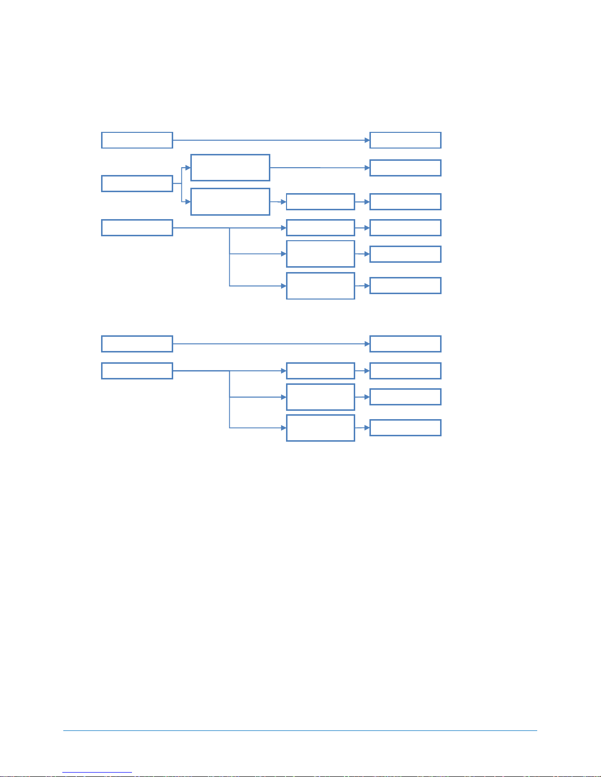
Refer to the section in accordance with your disk form factor and RAID configuration.
4.1.1 Hot Plug 2.5-inch Drive Configuration
Up to eight 2.5-inch Drives
Up to sixteen 2.5-inch Drives with two RAID Controllers
Up to twenty four 2.5-inch Drives with three RAID Controllers
Non-RAID
RAID 5/6/50/60
512 MB Cache
1GB Cache/
Battery
512 MB Cache
Refer to 4.2.1
Refer to 4.2.3
Refer to 4.2.4
Refer to 4.2.5
RAID 0/1/10
SATA
SAS, SATA
SAS, SATA
SAS, SATA
Available Interface
Embedded SATA
RAID Controller
Optional RAID
Controller
Refer to 4.2.2
SATA
1GB Cache/
CacheVault
Refer to 4.2.6
SAS, SATA
RAID 0/1/10
RAID 5/6/50/60
1GB Cache/
Battery
512 MB Cache
Refer to 4.2.8
Refer to 4.2.9
SAS, SATA
SAS, SATA
Available Interface
Refer to 4.2.7
SAS, SATA
1GB Cache/
CacheVault
Refer to 4.2.10
SAS, SATA
RAID 0/1/10
RAID 5/6/50/60
1GB Cache/
Battery
512 MB Cache
Refer to 4.2.12
Refer to 4.2.13
SAS, SATA
SAS, SATA
Available Interface
Refer to 4.2.11
SAS, SATA
1GB Cache/
CacheVault
Refer to 4.2.14
SAS, SATA
Page 16

CONFIGURATION GUIDE – NEC Express5800/T120d
NEC Corporation Revision 7.0 – October 25, 2013 16
Up to sixteen 2.5-inch Drives with SAS Expander Card
Up to twenty four 2.5-inch Drives with SAS Expander Card
NOTE:
Embedded SATA controller can connect to up to four drives.
Embedded SATA RAID controller is supported only on Windows operating systems. An optional RAID
controller is required to configure RAID array for other operating systems.
Hot plug insertion/removal is not supported with the Embedded SATA non-RAID controller.
All drives within a RAID array should be of the same type, capacity and rotation speed.
If multiple RAID controllers are mounted, the RAID controllers must be identical.
To install more than sixteen drives, N8181-98 Redundant Fan kit must be installed
Up to two different types of drive can be used in the same drive cage. Two mixed drives in multiple
drive cages are required to install more than three different types of drive.
For optional RAID controller driver to install Windows Server 2003 R2, download from the NEC
website at:
http://www.nec.com/en/global/prod/express/download/index.html
RAID 0/1/10
RAID 5/6/50/60
1GB Cache/
Battery
512 MB Cache
Refer to 4.2.16
Refer to 4.2.17
SAS, SATA
SAS, SATA
Available Interface
Refer to 4.2.15
SAS, SATA
1GB Cache/
CacheVault
Refer to 4.2.18
SAS, SATA
RAID 0/1/10
RAID 5/6/50/60
1GB Cache/
Battery
512 MB Cache
Refer to 4.2.20
Refer to 4.2.21
SAS, SATA
SAS, SATA
Available Interface
Refer to 4.2.19
SAS, SATA
1GB Cache/
CacheVault
Refer to 4.2.22
SAS, SATA
Page 17
CONFIGURATION GUIDE – NEC Express5800/T120d
NEC Corporation Revision 7.0 – October 25, 2013 17
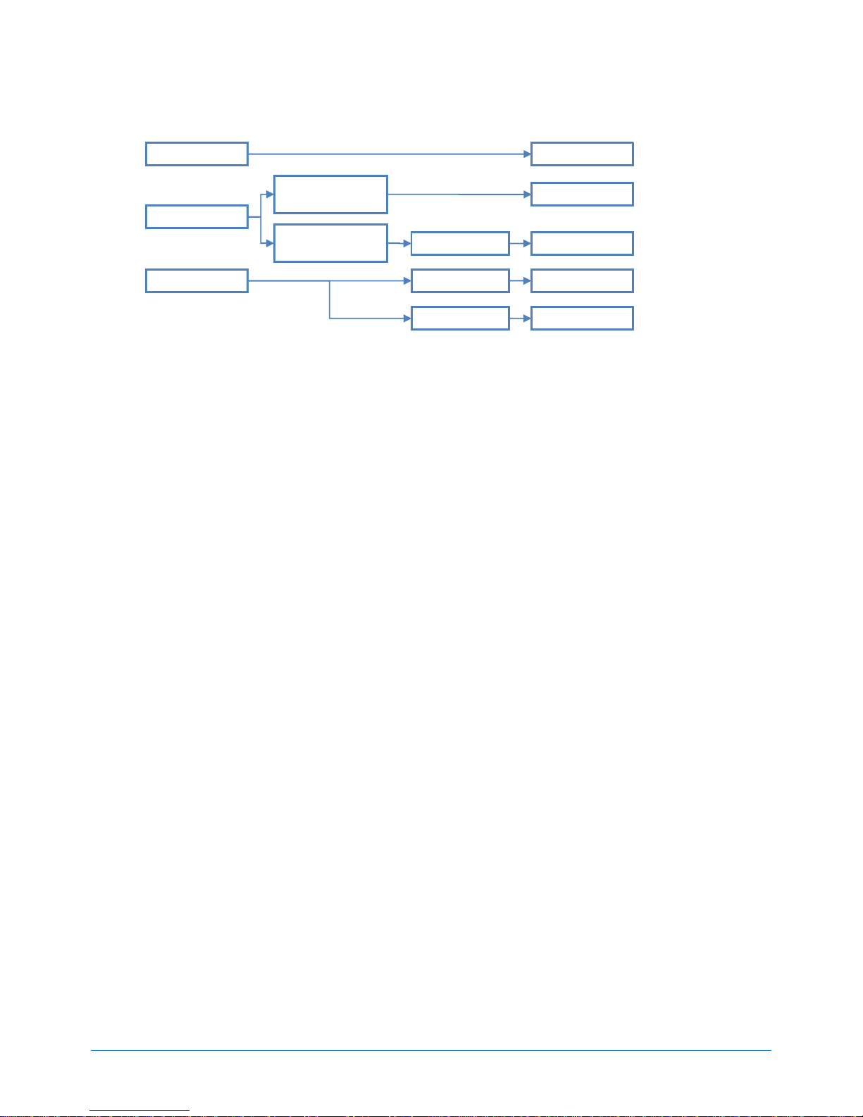
4.1.2 Hot Plug 3.5-inch Drive Configuration
Up to four 3.5-inch Drives
Up to eight 3.5-inch Drives
NOTE:
Embedded SATA RAID controller is supported only on Windows operating systems. An optional RAID
controller is required to configure RAID array for other operating systems.
Embedded SATA RAID Controller does not support RAID 10 configured with 2TB and 3TB HDDs.
Hot plug insertion/removal is not supported with the Embedded SATA non-RAID controller.
All hard drives within a RAID array should be of the same capacity.
An optional RAID controller occupies one PCI slot.
For optional RAID controller driver to install Windows Server 2003 R2, download from the NEC
website at:
http://www.nec.com/en/global/prod/express/download/index.html
Non-RAID
RAID 5/6/50/60
512 MB Cache
1GB Cache/
Battery
512 MB Cache
Refer to 4.3.1
Refer to 4.3.3
Refer to 4.3.4
Refer to 4.3.5
RAID 0/1/10
SATA
SATA
SATA
SATA
Available Interface
Embedded SATA
RAID Controller
Optional RAID
Controller
Refer to 4.3.2
SATA
1GB Cache/
CacheVault
Refer to 4.3.6
SATA
RAID 0/1/10
RAID 5/6/50/60
1GB Cache/
Battery
512 MB Cache
Refer to 4.3.8
Refer to 4.3.9
SATA
SATA
Available Interface
Refer to 4.3.7
SATA
1GB Cache/
CacheVault
Refer to 4.3.10
SATA
Page 18
CONFIGURATION GUIDE – NEC Express5800/T120d
NEC Corporation Revision 7.0 – October 25, 2013 18
4.1.3 Non-hot Plug 3.5-inch Drive Configuration
NOTE:
Embedded SATA RAID controller is supported only on Windows operating systems. An optional RAID
controller is required to configure RAID array for other operating systems.
Embedded SATA RAID Controller does not support RAID 10 configured with 2TB and 3TB HDDs.
Hot plug insertion/removal is not supported with the Embedded SATA non-RAID controller.
All hard drives within a RAID array should be of the same capacity.
An optional RAID controller occupies one PCI slot.
For optional RAID controller driver to install Windows Server 2003 R2, download from the NEC
website at:
http://www.nec.com/en/global/prod/express/download/index.html
Non-RAID
RAID 5/6/50/60
512 MB Cache
1GB Cache
512 MB Cache
Refer to 4.4.1
Refer to 4.4.3
Refer to 4.4.5
RAID 0/1/10
SATA
SATA
SATA
SATA
Available Interface
Embedded SATA
RAID Controller
Optional RAID
Controller
Refer to 4.4.2
SATA
Refer to 4.4.4
Page 19

CONFIGURATION GUIDE – NEC Express5800/T120d
NEC Corporation Revision 7.0 – October 25, 2013 19
4.2 Hot Plug 2.5-inch Internal Drive Configuration
4.2.1 Up to 4 Drive with Embedded SATA non-RAID Controller
Category
Product Name / Description
Part Number
Storage Controller
Embedded SATA Controller
2x 6Gb/s SATA, 2x 3Gb/s SATA
(Standard)
Cable
Required
Internal SATA Cable
4 x Single SATA to 1 x mini-SAS
K410-258(00)
Drive Cage
Required
2.5-inch Hot Plug Drive Cage Kit
8 x 2.5-inch hot plug hard drive bays
N8154-42F
Drive
4 slots
available
SATA
HDD
250GB 7.2K Hot Plug 2.5-inch SATA HDD
1x 250 GB SATA HDD, 2.5-inch, 6Gb/s, 7,200 rpm
N8150-356
500GB 7.2K Hot Plug 2.5-inch SATA HDD
1x 500 GB SATA HDD, 2.5-inch, 6Gb/s, 7,200 rpm
N8150-357
1TB 7.2K Hot Plug 2.5-inch SATA HDD
1x 1 TB SATA HDD, 2.5-inch, 6Gb/s, 7,200 rpm
N8150-358
NOTE:
Hot plug insertion/removal is not supported with the Embedded SATA non-RAID controller.
4.2.2 Up to 4 Drive with Embedded SATA RAID Controller
Category
Product Name / Description
Part Number
Storage Controller
Embedded SATA Controller
2x 6Gb/s SATA, 2x 3Gb/s SATA, RAID 0/1/10 capable
(Standard)
Cable
Required
Internal SATA Cable
4 x Single SATA to 1 x mini-SAS
K410-258(00)
Drive Cage
Required
2.5-inch Hot Plug Drive Cage Kit
8 x 2.5-inch hot plug hard drive bays
N8154-42F
Drive
4 slots
available
SATA
HDD
250GB 7.2K Hot Plug 2.5-inch SATA HDD
1x 250 GB SATA HDD, 2.5-inch, 6Gb/s, 7,200 rpm
N8150-356
500GB 7.2K Hot Plug 2.5-inch SATA HDD
1x 500 GB SATA HDD, 2.5-inch, 6Gb/s, 7,200 rpm
N8150-357
1TB 7.2K Hot Plug 2.5-inch SATA HDD
1x 1 TB SATA HDD, 2.5-inch, 6Gb/s, 7,200 rpm
N8150-358
NOTE:
Embedded SATA RAID controller is supported only on Windows operating systems. An optional RAID
controller is required to configure RAID array for other operating systems.
All hard drives within a RAID array should be of the same capacity.
Page 20

CONFIGURATION GUIDE – NEC Express5800/T120d
NEC Corporation Revision 7.0 – October 25, 2013 20
4.2.3 Up to 8 Drives with RAID 0/1 Controller with 512 MB Cache
Category
Product Name / Description
Part Number
Storage Controller
Required
RAID Controller (512MB, RAID 0/1)
LSI MegaRAID SAS 9267-8i
RAID 0/1, 512 MB, Int. 8, PCIe 2.0 x8, SAS 6Gb/s, SATA
6Gb/s
N8103-149
RAID BBU
Recommended
RAID Battery Backup Unit
for LSI MegaRAID SAS 9267-8i
N8103-154
Cable
1 to 2 Required
Internal SAS/SATA Cable
1 x mini-SAS to 1 x mini-SAS
NOTE: To install five drives or more, two sets of cable are
required.
K410-274(00)
Drive Cage
Required
2.5-inch Hot Plug Drive Cage Kit
8 x 2.5-inch hot plug hard drive bays
N8154-42F
Drive
4 to 8 slots
available
SAS
HDD
300GB 10K Hot Plug 2.5-inch SAS HDD
1 x 300 GB SAS HDD, 2.5-inch, 6Gb/s, 10,000 rpm
N8150-301
450GB 10K Hot Plug 2.5-inch SAS HDD
1 x 450 GB SAS HDD, 2.5-inch, 6Gb/s, 10,000 rpm
N8150-322
600GB 10K Hot Plug 2.5-inch SAS HDD
1 x 600 GB SAS HDD, 2.5-inch, 6Gb/s, 10,000 rpm
N8150-304
900GB 10K Hot Plug 2.5-inch SAS HDD
1x 900 GB SAS HDD, 2.5-inch, 6Gb/s, 10,000 rpm
N8150-332
1.2TB 10K Hot Plug 2.5-inch SAS HDD
1x 1.2TB SAS HDD, 2.5-inch, 6Gb/s, 10,000 rpm
N8150-408
73.2GB 15K Hot Plug 2.5-inch SAS HDD
1x 73.2 GB SAS HDD, 2.5-inch, 6Gb/s, 15,000 rpm
N8150-302
146.5GB 15K Hot Plug 2.5-inch SAS HDD
1x 146.5 GB SAS HDD, 2.5-inch, 6Gb/s, 15,000 rpm
N8150-303
300GB 15K Hot Plug 2.5-inch SAS HDD
1x 300 GB SAS HDD, 2.5-inch, 6Gb/s, 15,000 rpm
N8150-331
SATA
HDD
250GB 7.2K Hot Plug 2.5-inch SATA HDD
1x 250 GB SATA HDD, 2.5-inch, 6Gb/s, 7,200 rpm
N8150-356
500GB 7.2K Hot Plug 2.5-inch SATA HDD
1x 500 GB SATA HDD, 2.5-inch, 6Gb/s, 7,200 rpm
N8150-357
1TB 7.2K Hot Plug 2.5-inch SATA HDD
1x 1 TB SATA HDD, 2.5-inch, 6Gb/s, 7,200 rpm
N8150-358
SAS
SSD
200GB Hot Plug 2.5-inch SAS SSD
1x 200 GB SAS SSD, eMLC, 2.5-inch, 6Gb/s
N8150-711
400GB Hot Plug 2.5-inch SAS SSD
1x 400 GB SAS SSD, eMLC, 2.5-inch, 6Gb/s
N8150-712
NOTE:
All drives within a RAID array should be of the same type, capacity and rotation speed.
Up to two different types of drive can be used in the same drive cage.
For VMware ESXi 5.5 installation, to download the CIM provider (LSI SMI-S provider) is required.
Page 21

CONFIGURATION GUIDE – NEC Express5800/T120d
NEC Corporation Revision 7.0 – October 25, 2013 21
4.2.4 Up to 8 Drives with RAID 5/6 Controller with 512 MB Cache
Category
Product Name / Description
Part Number
Storage Controller
Required
RAID Controller (512MB, RAID 0/1/5/6)
LSI MegaRAID SAS 9267-8i
RAID0/1/5/6/10/50/60, 512MB, Int. 8, PCIe 2.0 x8, SAS 6Gb/s,
SATA 6Gb/s
N8103-150
RAID BBU
Recommended
RAID Battery Backup Unit
for LSI MegaRAID SAS 9267-8i
N8103-154
Cable
1 to 2 Required
Internal SAS/SATA Cable
1 x mini-SAS to 1 x mini-SAS
NOTE: To install five drives or more, two sets of cable are
required.
K410-274(00)
Drive Cage
Required
2.5-inch Hot Plug Drive Cage Kit
8 x 2.5-inch hot plug hard drive bays
N8154-42F
Drive
4 to 8 slots
available
SAS
HDD
300GB 10K Hot Plug 2.5-inch SAS HDD
1 x 300 GB SAS HDD, 2.5-inch, 6Gb/s, 10,000 rpm
N8150-301
450GB 10K Hot Plug 2.5-inch SAS HDD
1 x 450 GB SAS HDD, 2.5-inch, 6Gb/s, 10,000 rpm
N8150-322
600GB 10K Hot Plug 2.5-inch SAS HDD
1 x 600 GB SAS HDD, 2.5-inch, 6Gb/s, 10,000 rpm
N8150-304
900GB 10K Hot Plug 2.5-inch SAS HDD
1x 900 GB SAS HDD, 2.5-inch, 6Gb/s, 10,000 rpm
N8150-332
1.2TB 10K Hot Plug 2.5-inch SAS HDD
1x 1.2TB SAS HDD, 2.5-inch, 6Gb/s, 10,000 rpm
N8150-408
73.2GB 15K Hot Plug 2.5-inch SAS HDD
1x 73.2 GB SAS HDD, 2.5-inch, 6Gb/s, 15,000 rpm
N8150-302
146.5GB 15K Hot Plug 2.5-inch SAS HDD
1x 146.5 GB SAS HDD, 2.5-inch, 6Gb/s, 15,000 rpm
N8150-303
300GB 15K Hot Plug 2.5-inch SAS HDD
1x 300 GB SAS HDD, 2.5-inch, 6Gb/s, 15,000 rpm
N8150-331
SATA
HDD
250GB 7.2K Hot Plug 2.5-inch SATA HDD
1x 250 GB SATA HDD, 2.5-inch, 6Gb/s, 7,200 rpm
N8150-356
500GB 7.2K Hot Plug 2.5-inch SATA HDD
1x 500 GB SATA HDD, 2.5-inch, 6Gb/s, 7,200 rpm
N8150-357
1TB 7.2K Hot Plug 2.5-inch SATA HDD
1x 1 TB SATA HDD, 2.5-inch, 6Gb/s, 7,200 rpm
N8150-358
SAS
SSD
200GB Hot Plug 2.5-inch SAS SSD
1x 200 GB SAS SSD, eMLC, 2.5-inch, 6Gb/s
N8150-711
400GB Hot Plug 2.5-inch SAS SSD
1x 400 GB SAS SSD, eMLC, 2.5-inch, 6Gb/s
N8150-712
NOTE:
All drives within a RAID array should be of the same type, capacity and rotation speed.
Up to two different types of drive can be used in the same drive cage.
For VMware ESXi 5.5 installation, to download the CIM provider (LSI SMI-S provider) is required.
Page 22

CONFIGURATION GUIDE – NEC Express5800/T120d
NEC Corporation Revision 7.0 – October 25, 2013 22
4.2.5 Up to 8 Drives with RAID 5/6 Controller with 1 GB Cache/Battery
Category
Product Name / Description
Part Number
Storage Controller
Required
RAID Controller (1GB, RAID0/1/5/6)
LSI MegaRAID SAS 9267-8i
RAID 0/1/5/6/10/50/60, 1 GB, Int. 8, PCIe 2.0 x8, SAS 6Gb/s,
SATA 6Gb/s
N8103-151
RAID BBU
Recommended
RAID Battery Backup Unit
for LSI MegaRAID SAS 9267-8i
N8103-154
SSD Caching
Recommended
MegaRAID CacheCade
for LSI MegaRAID SAS
NOTE:
- SSD used for cache is required
- The SSD capacity which can be used as read cache is up to
512 GB.
N8103-156
Cable
1 to 2 Required
Internal SAS/SATA Cable
1 x mini-SAS to 1 x mini-SAS
NOTE: To install five drives or more, two sets of cable are
required.
K410-274(00)
Drive Cage
Required
2.5-inch Hot Plug Drive Cage Kit
8 x 2.5-inch hot plug hard drive bays
N8154-42F
Drive
4 to 8 slots
available
SAS
HDD
300GB 10K Hot Plug 2.5-inch SAS HDD
1 x 300 GB SAS HDD, 2.5-inch, 6Gb/s, 10,000 rpm
N8150-301
450GB 10K Hot Plug 2.5-inch SAS HDD
1 x 450 GB SAS HDD, 2.5-inch, 6Gb/s, 10,000 rpm
N8150-322
600GB 10K Hot Plug 2.5-inch SAS HDD
1 x 600 GB SAS HDD, 2.5-inch, 6Gb/s, 10,000 rpm
N8150-304
900GB 10K Hot Plug 2.5-inch SAS HDD
1x 900 GB SAS HDD, 2.5-inch, 6Gb/s, 10,000 rpm
N8150-332
1.2TB 10K Hot Plug 2.5-inch SAS HDD
1x 1.2TB SAS HDD, 2.5-inch, 6Gb/s, 10,000 rpm
N8150-408
73.2GB 15K Hot Plug 2.5-inch SAS HDD
1x 73.2 GB SAS HDD, 2.5-inch, 6Gb/s, 15,000 rpm
N8150-302
146.5GB 15K Hot Plug 2.5-inch SAS HDD
1x 146.5 GB SAS HDD, 2.5-inch, 6Gb/s, 15,000 rpm
N8150-303
300GB 15K Hot Plug 2.5-inch SAS HDD
1x 300 GB SAS HDD, 2.5-inch, 6Gb/s, 15,000 rpm
N8150-331
SATA
HDD
250GB 7.2K Hot Plug 2.5-inch SATA HDD
1x 250 GB SATA HDD, 2.5-inch, 6Gb/s, 7,200 rpm
N8150-356
500GB 7.2K Hot Plug 2.5-inch SATA HDD
1x 500 GB SATA HDD, 2.5-inch, 6Gb/s, 7,200 rpm
N8150-357
1TB 7.2K Hot Plug 2.5-inch SATA HDD
1x 1 TB SATA HDD, 2.5-inch, 6Gb/s, 7,200 rpm
N8150-358
SAS
SSD
200GB Hot Plug 2.5-inch SAS SSD
1x 200 GB SAS SSD, eMLC, 2.5-inch, 6Gb/s
N8150-711
400GB Hot Plug 2.5-inch SAS SSD
1x 400 GB SAS SSD, eMLC, 2.5-inch, 6Gb/s
N8150-712
NOTE:
All drives within a RAID array should be of the same type, capacity and rotation speed.
Up to two different types of drive can be used in the same drive cage.
For VMware ESXi 5.5 installation, to download the CIM provider (LSI SMI-S provider) is required.
Page 23

CONFIGURATION GUIDE – NEC Express5800/T120d
NEC Corporation Revision 7.0 – October 25, 2013 23
4.2.6 Up to 8 Drives with RAID 5/6 Controller with 1 GB Cache/CacheVault
Category
Product Name / Description
Part Number
Storage Controller
Required
RAID Controller (1GB, RAID 0/1/5/6)
LSI MegaRAID SAS 9270CV-8i (with CV)
RAID0/1/5/6/10/50/60, 1GB Cache, Int. 8ports, PCIe 3.0(x8),
6Gb/s, flash cache protection modules included
N8103-152
SSD Caching
Recommended
MegaRAID CacheCade
for LSI MegaRAID SAS
NOTE:
- SSD used for cache is required
- The SSD capacity which can be used as read cache is up to
512 GB.
N8103-156
Cable
1 to 2 Required
Internal SAS/SATA Cable
1 x mini-SAS to 1 x mini-SAS
NOTE: To install five drives or more, two sets of cable are
required.
K410-259(00)
Drive Cage
Required
2.5-inch Hot Plug Drive Cage Kit
8 x 2.5-inch hot plug hard drive bays
N8154-42F
Drive
4 to 8 slots
available
SAS
HDD
300GB 10K Hot Plug 2.5-inch SAS HDD
1 x 300 GB SAS HDD, 2.5-inch, 6Gb/s, 10,000 rpm
N8150-301
450GB 10K Hot Plug 2.5-inch SAS HDD
1 x 450 GB SAS HDD, 2.5-inch, 6Gb/s, 10,000 rpm
N8150-322
600GB 10K Hot Plug 2.5-inch SAS HDD
1 x 600 GB SAS HDD, 2.5-inch, 6Gb/s, 10,000 rpm
N8150-304
900GB 10K Hot Plug 2.5-inch SAS HDD
1x 900 GB SAS HDD, 2.5-inch, 6Gb/s, 10,000 rpm
N8150-332
1.2TB 10K Hot Plug 2.5-inch SAS HDD
1x 1.2TB SAS HDD, 2.5-inch, 6Gb/s, 10,000 rpm
N8150-408
73.2GB 15K Hot Plug 2.5-inch SAS HDD
1x 73.2 GB SAS HDD, 2.5-inch, 6Gb/s, 15,000 rpm
N8150-302
146.5GB 15K Hot Plug 2.5-inch SAS HDD
1x 146.5 GB SAS HDD, 2.5-inch, 6Gb/s, 15,000 rpm
N8150-303
300GB 15K Hot Plug 2.5-inch SAS HDD
1x 300 GB SAS HDD, 2.5-inch, 6Gb/s, 15,000 rpm
N8150-331
SATA
HDD
250GB 7.2K Hot Plug 2.5-inch SATA HDD
1x 250 GB SATA HDD, 2.5-inch, 6Gb/s, 7,200 rpm
N8150-356
500GB 7.2K Hot Plug 2.5-inch SATA HDD
1x 500 GB SATA HDD, 2.5-inch, 6Gb/s, 7,200 rpm
N8150-357
1TB 7.2K Hot Plug 2.5-inch SATA HDD
1x 1 TB SATA HDD, 2.5-inch, 6Gb/s, 7,200 rpm
N8150-358
SAS
SSD
200GB Hot Plug 2.5-inch SAS SSD
1x 200 GB SAS SSD, eMLC, 2.5-inch, 6Gb/s
N8150-711
400GB Hot Plug 2.5-inch SAS SSD
1x 400 GB SAS SSD, eMLC, 2.5-inch, 6Gb/s
N8150-712
NOTE:
All drives within a RAID array should be of the same type, capacity and rotation speed.
Up to two different types of drive can be used in the same drive cage.
For VMware ESXi 5.x installation, to download the CIM provider (LSI SMI-S provider) is required.
Page 24

CONFIGURATION GUIDE – NEC Express5800/T120d
NEC Corporation Revision 7.0 – October 25, 2013 24
4.2.7 Up to 16 Drives with RAID 0/1 Controller with 512 MB Cache
Category
Product Name / Description
Part Number
Storage Controller
2 Required
RAID Controller (512MB, RAID 0/1)
LSI MegaRAID SAS 9267-8i
RAID 0/1, 512 MB, Int. 8, PCIe 2.0 x8, SAS 6Gb/s, SATA
6Gb/s
N8103-149
RAID BBU
2 Recommended
RAID Battery Backup Unit
for LSI MegaRAID SAS 9267-8i
N8103-154
Cable
3 to 4 Required
Internal SAS/SATA Cable
1 x mini-SAS to 1 x mini-SAS
NOTE: To install thirteen drives or more, four sets of cable
are required.
K410-274(00)
Drive Cage
2 Required
2.5-inch Hot Plug Drive Cage Kit
8 x 2.5-inch hot plug hard drive bays
N8154-42F
Drive
12 to 16
slots
available
SAS
HDD
300GB 10K Hot Plug 2.5-inch SAS HDD
1 x 300 GB SAS HDD, 2.5-inch, 6Gb/s, 10,000 rpm
N8150-301
450GB 10K Hot Plug 2.5-inch SAS HDD
1 x 450 GB SAS HDD, 2.5-inch, 6Gb/s, 10,000 rpm
N8150-322
600GB 10K Hot Plug 2.5-inch SAS HDD
1 x 600 GB SAS HDD, 2.5-inch, 6Gb/s, 10,000 rpm
N8150-304
900GB 10K Hot Plug 2.5-inch SAS HDD
1x 900 GB SAS HDD, 2.5-inch, 6Gb/s, 10,000 rpm
N8150-332
1.2TB 10K Hot Plug 2.5-inch SAS HDD
1x 1.2TB SAS HDD, 2.5-inch, 6Gb/s, 10,000 rpm
N8150-408
73.2GB 15K Hot Plug 2.5-inch SAS HDD
1x 73.2 GB SAS HDD, 2.5-inch, 6Gb/s, 15,000 rpm
N8150-302
146.5GB 15K Hot Plug 2.5-inch SAS HDD
1x 146.5 GB SAS HDD, 2.5-inch, 6Gb/s, 15,000 rpm
N8150-303
300GB 15K Hot Plug 2.5-inch SAS HDD
1x 300 GB SAS HDD, 2.5-inch, 6Gb/s, 15,000 rpm
N8150-331
SATA
HDD
250GB 7.2K Hot Plug 2.5-inch SATA HDD
1x 250 GB SATA HDD, 2.5-inch, 6Gb/s, 7,200 rpm
N8150-356
500GB 7.2K Hot Plug 2.5-inch SATA HDD
1x 500 GB SATA HDD, 2.5-inch, 6Gb/s, 7,200 rpm
N8150-357
1TB 7.2K Hot Plug 2.5-inch SATA HDD
1x 1 TB SATA HDD, 2.5-inch, 6Gb/s, 7,200 rpm
N8150-358
SAS
SSD
200GB Hot Plug 2.5-inch SAS SSD
1x 200 GB SAS SSD, eMLC, 2.5-inch, 6Gb/s
N8150-711
400GB Hot Plug 2.5-inch SAS SSD
1x 400 GB SAS SSD, eMLC, 2.5-inch, 6Gb/s
N8150-712
NOTE:
All drives within a RAID array should be of the same type, capacity and rotation speed.
Up to two different types of drive can be used in the same drive cage. Two mixed drives in multiple
drive cages are required to install more than three different types of drive.
For VMware ESXi 5.5 installation, to download the CIM provider (LSI SMI-S provider) is required.
Page 25

CONFIGURATION GUIDE – NEC Express5800/T120d
NEC Corporation Revision 7.0 – October 25, 2013 25
4.2.8 Up to 16 Drives with RAID 5/6 Controller with 512 MB Cache
Category
Product Name / Description
Part Number
Storage Controller
2 Required
RAID Controller (512MB, RAID 0/1/5/6)
LSI MegaRAID SAS 9267-8i
RAID 0/1/5/6/10/50/60, 512MB, Int. 8, PCIe 2.0 x8, SAS
6Gb/s, SATA 6Gb/s
N8103-150
RAID BBU
2 Recommended
RAID Battery Backup Unit
for LSI MegaRAID SAS 9267-8i
N8103-154
Cable
3 to 4 Required
Internal SAS/SATA Cable
1 x mini-SAS to 1 x mini-SAS
NOTE: To install thirteen drives or more, four sets of cable
are required.
K410-274(00)
Drive Cage
2 Required
2.5-inch Hot Plug Drive Cage Kit
8 x 2.5-inch hot plug hard drive bays
N8154-42F
Drive
12 to 16
slots
available
SAS
HDD
300GB 10K Hot Plug 2.5-inch SAS HDD
1 x 300 GB SAS HDD, 2.5-inch, 6Gb/s, 10,000 rpm
N8150-301
450GB 10K Hot Plug 2.5-inch SAS HDD
1 x 450 GB SAS HDD, 2.5-inch, 6Gb/s, 10,000 rpm
N8150-322
600GB 10K Hot Plug 2.5-inch SAS HDD
1 x 600 GB SAS HDD, 2.5-inch, 6Gb/s, 10,000 rpm
N8150-304
900GB 10K Hot Plug 2.5-inch SAS HDD
1x 900 GB SAS HDD, 2.5-inch, 6Gb/s, 10,000 rpm
N8150-332
1.2TB 10K Hot Plug 2.5-inch SAS HDD
1x 1.2TB SAS HDD, 2.5-inch, 6Gb/s, 10,000 rpm
N8150-408
73.2GB 15K Hot Plug 2.5-inch SAS HDD
1x 73.2 GB SAS HDD, 2.5-inch, 6Gb/s, 15,000 rpm
N8150-302
146.5GB 15K Hot Plug 2.5-inch SAS HDD
1x 146.5 GB SAS HDD, 2.5-inch, 6Gb/s, 15,000 rpm
N8150-303
300GB 15K Hot Plug 2.5-inch SAS HDD
1x 300 GB SAS HDD, 2.5-inch, 6Gb/s, 15,000 rpm
N8150-331
SATA
HDD
250GB 7.2K Hot Plug 2.5-inch SATA HDD
1x 250 GB SATA HDD, 2.5-inch, 6Gb/s, 7,200 rpm
N8150-356
500GB 7.2K Hot Plug 2.5-inch SATA HDD
1x 500 GB SATA HDD, 2.5-inch, 6Gb/s, 7,200 rpm
N8150-357
1TB 7.2K Hot Plug 2.5-inch SATA HDD
1x 1 TB SATA HDD, 2.5-inch, 6Gb/s, 7,200 rpm
N8150-358
SAS
SSD
200GB Hot Plug 2.5-inch SAS SSD
1x 200 GB SAS SSD, eMLC, 2.5-inch, 6Gb/s
N8150-711
400GB Hot Plug 2.5-inch SAS SSD
1x 400 GB SAS SSD, eMLC, 2.5-inch, 6Gb/s
N8150-712
NOTE:
All drives within a RAID array should be of the same type, capacity and rotation speed.
Up to two different types of drive can be used in the same drive cage. Two mixed drives in multiple
drive cages are required to install more than three different types of drive.
For VMware ESXi 5.5 installation, to download the CIM provider (LSI SMI-S provider) is required.
Page 26

CONFIGURATION GUIDE – NEC Express5800/T120d
NEC Corporation Revision 7.0 – October 25, 2013 26
4.2.9 Up to 16 Drives with RAID 5/6 Controller with 1 GB Cache/Battery
Category
Product Name / Description
Part Number
Storage Controller
2 Required
RAID Controller (1GB, RAID0/1/5/6)
LSI MegaRAID SAS 9267-8i
RAID 0/1/5/6/10/50/60, 1 GB, Int. 8, PCIe 2.0 x8, SAS 6Gb/s,
SATA 6Gb/s
N8103-151
RAID BBU
2 Recommended
RAID Battery Backup Unit
for LSI MegaRAID SAS 9267-8i
N8103-154
SSD Caching
2 Recommended
MegaRAID CacheCade
for LSI MegaRAID SAS
NOTE:
- SSD used for cache is required
- The SSD capacity which can be used as read cache is up to
512 GB.
N8103-156
Cable
3 to 4 Required
Internal SAS/SATA Cable
1 x mini-SAS to 1 x mini-SAS
NOTE: To install thirteen drives or more, four sets of cable
are required.
K410-274(00)
Drive Cage
Required
2.5-inch Hot Plug Drive Cage Kit
8 x 2.5-inch hot plug hard drive bays
N8154-42F
Drive
12 to 16
slots
available
SAS
HDD
300GB 10K Hot Plug 2.5-inch SAS HDD
1 x 300 GB SAS HDD, 2.5-inch, 6Gb/s, 10,000 rpm
N8150-301
450GB 10K Hot Plug 2.5-inch SAS HDD
1 x 450 GB SAS HDD, 2.5-inch, 6Gb/s, 10,000 rpm
N8150-322
600GB 10K Hot Plug 2.5-inch SAS HDD
1 x 600 GB SAS HDD, 2.5-inch, 6Gb/s, 10,000 rpm
N8150-304
900GB 10K Hot Plug 2.5-inch SAS HDD
1x 900 GB SAS HDD, 2.5-inch, 6Gb/s, 10,000 rpm
N8150-332
1.2TB 10K Hot Plug 2.5-inch SAS HDD
1x 1.2TB SAS HDD, 2.5-inch, 6Gb/s, 10,000 rpm
N8150-408
73.2GB 15K Hot Plug 2.5-inch SAS HDD
1x 73.2 GB SAS HDD, 2.5-inch, 6Gb/s, 15,000 rpm
N8150-302
146.5GB 15K Hot Plug 2.5-inch SAS HDD
1x 146.5 GB SAS HDD, 2.5-inch, 6Gb/s, 15,000 rpm
N8150-303
300GB 15K Hot Plug 2.5-inch SAS HDD
1x 300 GB SAS HDD, 2.5-inch, 6Gb/s, 15,000 rpm
N8150-331
SATA
HDD
250GB 7.2K Hot Plug 2.5-inch SATA HDD
1x 250 GB SATA HDD, 2.5-inch, 6Gb/s, 7,200 rpm
N8150-356
500GB 7.2K Hot Plug 2.5-inch SATA HDD
1x 500 GB SATA HDD, 2.5-inch, 6Gb/s, 7,200 rpm
N8150-357
1TB 7.2K Hot Plug 2.5-inch SATA HDD
1x 1 TB SATA HDD, 2.5-inch, 6Gb/s, 7,200 rpm
N8150-358
SAS
SSD
200GB Hot Plug 2.5-inch SAS SSD
1x 200 GB SAS SSD, eMLC, 2.5-inch, 6Gb/s
N8150-711
400GB Hot Plug 2.5-inch SAS SSD
1x 400 GB SAS SSD, eMLC, 2.5-inch, 6Gb/s
N8150-712
NOTE:
All drives within a RAID array should be of the same type, capacity and rotation speed.
Up to two different types of drive can be used in the same drive cage. Two mixed drives in multiple
drive cages are required to install more than three different types of drive.
For VMware ESXi 5.5 installation, to download the CIM provider (LSI SMI-S provider) is required.
Page 27

CONFIGURATION GUIDE – NEC Express5800/T120d
NEC Corporation Revision 7.0 – October 25, 2013 27
4.2.10 Up to 16 Drives with RAID 5/6 Controller with 1 GB Cache/CacheVault
Category
Product Name / Description
Part Number
Storage Controller
2 Required
RAID Controller (1GB, RAID 0/1/5/6)
LSI MegaRAID SAS 9270CV-8i (with CV)
RAID0/1/5/6/10/50/60, 1GB Cache, Int. 8ports, PCIe 3.0(x8),
6Gb/s, flash cache protection modules included
N8103-152
SSD Caching
2 Recommended
MegaRAID CacheCade
for LSI MegaRAID SAS
NOTE:
- SSD used for cache is required
- The SSD capacity which can be used as read cache is up to
512 GB.
N8103-156
Cable
2 Required
Internal SAS/SATA Cable
1 x mini-SAS to 1 x mini-SAS
K410-259(00)
Cable
1 to 2 Required
Internal SAS/SATA Cable
1 x mini-SAS to 1 x mini-SAS
NOTE: To install thirteen drives or more, two sets of cable
are required.
K410-274(00)
Drive Cage
Required
2.5-inch Hot Plug Drive Cage Kit
8 x 2.5-inch hot plug hard drive bays
N8154-42F
Drive
12 to 16
slots
available
SAS
HDD
300GB 10K Hot Plug 2.5-inch SAS HDD
1 x 300 GB SAS HDD, 2.5-inch, 6Gb/s, 10,000 rpm
N8150-301
450GB 10K Hot Plug 2.5-inch SAS HDD
1 x 450 GB SAS HDD, 2.5-inch, 6Gb/s, 10,000 rpm
N8150-322
600GB 10K Hot Plug 2.5-inch SAS HDD
1 x 600 GB SAS HDD, 2.5-inch, 6Gb/s, 10,000 rpm
N8150-304
900GB 10K Hot Plug 2.5-inch SAS HDD
1x 900 GB SAS HDD, 2.5-inch, 6Gb/s, 10,000 rpm
N8150-332
1.2TB 10K Hot Plug 2.5-inch SAS HDD
1x 1.2TB SAS HDD, 2.5-inch, 6Gb/s, 10,000 rpm
N8150-408
73.2GB 15K Hot Plug 2.5-inch SAS HDD
1x 73.2 GB SAS HDD, 2.5-inch, 6Gb/s, 15,000 rpm
N8150-302
146.5GB 15K Hot Plug 2.5-inch SAS HDD
1x 146.5 GB SAS HDD, 2.5-inch, 6Gb/s, 15,000 rpm
N8150-303
300GB 15K Hot Plug 2.5-inch SAS HDD
1x 300 GB SAS HDD, 2.5-inch, 6Gb/s, 15,000 rpm
N8150-331
SATA
HDD
250GB 7.2K Hot Plug 2.5-inch SATA HDD
1x 250 GB SATA HDD, 2.5-inch, 6Gb/s, 7,200 rpm
N8150-356
500GB 7.2K Hot Plug 2.5-inch SATA HDD
1x 500 GB SATA HDD, 2.5-inch, 6Gb/s, 7,200 rpm
N8150-357
1TB 7.2K Hot Plug 2.5-inch SATA HDD
1x 1 TB SATA HDD, 2.5-inch, 6Gb/s, 7,200 rpm
N8150-358
SAS
SSD
200GB Hot Plug 2.5-inch SAS SSD
1x 200 GB SAS SSD, eMLC, 2.5-inch, 6Gb/s
N8150-711
400GB Hot Plug 2.5-inch SAS SSD
1x 400 GB SAS SSD, eMLC, 2.5-inch, 6Gb/s
N8150-712
NOTE:
All drives within a RAID array should be of the same type, capacity and rotation speed.
Up to two different types of drive can be used in the same drive cage. Two mixed drives in multiple
drive cages are required to install more than three different types of drive.
For VMware ESXi 5.x installation, to download the CIM provider (LSI SMI-S provider) is required.
Page 28

CONFIGURATION GUIDE – NEC Express5800/T120d
NEC Corporation Revision 7.0 – October 25, 2013 28
4.2.11 Up to 24 Drives with RAID 0/1 Controller with 512 MB Cache
Category
Product Name / Description
Part Number
Storage Controller
3 Required
RAID Controller (512MB, RAID 0/1)
LSI MegaRAID SAS 9267-8i
RAID 0/1, 512 MB, Int. 8, PCIe 2.0 x8, SAS 6Gb/s, SATA
6Gb/s
N8103-149
RAID BBU
3 Recommended
RAID Battery Backup Unit
for LSI MegaRAID SAS 9267-8i
N8103-154
Cable
5 to 6 Required
Internal SAS/SATA Cable
1 x mini-SAS to 1 x mini-SAS
NOTE: To install twenty one drives or more, six sets of
cable are required.
K410-274(00)
Drive Cage
3 Required
2.5-inch Hot Plug Drive Cage Kit
8 x 2.5-inch hot plug hard drive bays
N8154-42F
Drive
20 to 24
slots
available
SAS
HDD
300GB 10K Hot Plug 2.5-inch SAS HDD
1 x 300 GB SAS HDD, 2.5-inch, 6Gb/s, 10,000 rpm
N8150-301
450GB 10K Hot Plug 2.5-inch SAS HDD
1 x 450 GB SAS HDD, 2.5-inch, 6Gb/s, 10,000 rpm
N8150-322
600GB 10K Hot Plug 2.5-inch SAS HDD
1 x 600 GB SAS HDD, 2.5-inch, 6Gb/s, 10,000 rpm
N8150-304
900GB 10K Hot Plug 2.5-inch SAS HDD
1x 900 GB SAS HDD, 2.5-inch, 6Gb/s, 10,000 rpm
N8150-332
1.2TB 10K Hot Plug 2.5-inch SAS HDD
1x 1.2TB SAS HDD, 2.5-inch, 6Gb/s, 10,000 rpm
N8150-408
73.2GB 15K Hot Plug 2.5-inch SAS HDD
1x 73.2 GB SAS HDD, 2.5-inch, 6Gb/s, 15,000 rpm
N8150-302
146.5GB 15K Hot Plug 2.5-inch SAS HDD
1x 146.5 GB SAS HDD, 2.5-inch, 6Gb/s, 15,000 rpm
N8150-303
300GB 15K Hot Plug 2.5-inch SAS HDD
1x 300 GB SAS HDD, 2.5-inch, 6Gb/s, 15,000 rpm
N8150-331
SATA
HDD
250GB 7.2K Hot Plug 2.5-inch SATA HDD
1x 250 GB SATA HDD, 2.5-inch, 6Gb/s, 7,200 rpm
N8150-356
500GB 7.2K Hot Plug 2.5-inch SATA HDD
1x 500 GB SATA HDD, 2.5-inch, 6Gb/s, 7,200 rpm
N8150-357
1TB 7.2K Hot Plug 2.5-inch SATA HDD
1x 1 TB SATA HDD, 2.5-inch, 6Gb/s, 7,200 rpm
N8150-358
SAS
SSD
200GB Hot Plug 2.5-inch SAS SSD
1x 200 GB SAS SSD, eMLC, 2.5-inch, 6Gb/s
N8150-711
400GB Hot Plug 2.5-inch SAS SSD
1x 400 GB SAS SSD, eMLC, 2.5-inch, 6Gb/s
N8150-712
NOTE:
All drives within a RAID array should be of the same type, capacity and rotation speed.
Up to two different types of drive can be used in the same drive cage. Two mixed drives in multiple
drive cages are required to install more than three different types of drive.
N8181-98 Redundant Fan kit must be installed.
For VMware ESXi 5.5 installation, to download the CIM provider (LSI SMI-S provider) is required.
Page 29

CONFIGURATION GUIDE – NEC Express5800/T120d
NEC Corporation Revision 7.0 – October 25, 2013 29
4.2.12 Up to 24 Drives with RAID 5/6 Controller with 512 MB Cache
Category
Product Name / Description
Part Number
Storage Controller
3 Required
RAID Controller (512MB, RAID 0/1/5/6)
LSI MegaRAID SAS 9267-8i
RAID 0/1/5/6/10/50/60, 512MB, Int. 8, PCIe 2.0 x8, SAS
6Gb/s, SATA 6Gb/s
N8103-150
RAID BBU
3 Recommended
RAID Battery Backup Unit
for LSI MegaRAID SAS 9267-8i
N8103-154
Cable
5 to 6 Required
Internal SAS/SATA Cable
1 x mini-SAS to 1 x mini-SAS
NOTE: To install twenty one drives or more, six sets of
cable are required.
K410-274(00)
Drive Cage
3 Required
2.5-inch Hot Plug Drive Cage Kit
8 x 2.5-inch hot plug hard drive bays
N8154-42F
Drive
20 to 24
slots
available
SAS
HDD
300GB 10K Hot Plug 2.5-inch SAS HDD
1 x 300 GB SAS HDD, 2.5-inch, 6Gb/s, 10,000 rpm
N8150-301
450GB 10K Hot Plug 2.5-inch SAS HDD
1 x 450 GB SAS HDD, 2.5-inch, 6Gb/s, 10,000 rpm
N8150-322
600GB 10K Hot Plug 2.5-inch SAS HDD
1 x 600 GB SAS HDD, 2.5-inch, 6Gb/s, 10,000 rpm
N8150-304
900GB 10K Hot Plug 2.5-inch SAS HDD
1x 900 GB SAS HDD, 2.5-inch, 6Gb/s, 10,000 rpm
N8150-332
1.2TB 10K Hot Plug 2.5-inch SAS HDD
1x 1.2TB SAS HDD, 2.5-inch, 6Gb/s, 10,000 rpm
N8150-408
73.2GB 15K Hot Plug 2.5-inch SAS HDD
1x 73.2 GB SAS HDD, 2.5-inch, 6Gb/s, 15,000 rpm
N8150-302
146.5GB 15K Hot Plug 2.5-inch SAS HDD
1x 146.5 GB SAS HDD, 2.5-inch, 6Gb/s, 15,000 rpm
N8150-303
300GB 15K Hot Plug 2.5-inch SAS HDD
1x 300 GB SAS HDD, 2.5-inch, 6Gb/s, 15,000 rpm
N8150-331
SATA
HDD
250GB 7.2K Hot Plug 2.5-inch SATA HDD
1x 250 GB SATA HDD, 2.5-inch, 6Gb/s, 7,200 rpm
N8150-356
500GB 7.2K Hot Plug 2.5-inch SATA HDD
1x 500 GB SATA HDD, 2.5-inch, 6Gb/s, 7,200 rpm
N8150-357
1TB 7.2K Hot Plug 2.5-inch SATA HDD
1x 1 TB SATA HDD, 2.5-inch, 6Gb/s, 7,200 rpm
N8150-358
SAS
SSD
200GB Hot Plug 2.5-inch SAS SSD
1x 200 GB SAS SSD, eMLC, 2.5-inch, 6Gb/s
N8150-711
400GB Hot Plug 2.5-inch SAS SSD
1x 400 GB SAS SSD, eMLC, 2.5-inch, 6Gb/s
N8150-712
NOTE:
All drives within a RAID array should be of the same type, capacity and rotation speed.
Up to two different types of drive can be used in the same drive cage. Two mixed drives in multiple
drive cages are required to install more than three different types of drive.
N8181-98 Redundant Fan kit must be installed.
For VMware ESXi 5.5 installation, to download the CIM provider (LSI SMI-S provider) is required.
Page 30

CONFIGURATION GUIDE – NEC Express5800/T120d
NEC Corporation Revision 7.0 – October 25, 2013 30
4.2.13 Up to 24 Drives with RAID 5/6 Controller with 1 GB Cache/Battery
Category
Product Name / Description
Part Number
Storage Controller
3 Required
RAID Controller (1GB, RAID0/1/5/6)
LSI MegaRAID SAS 9267-8i
RAID 0/1/5/6/10/50/60, 1 GB, Int. 8, PCIe 2.0 x8, SAS 6Gb/s,
SATA 6Gb/s
N8103-151
RAID BBU
3 Recommended
RAID Battery Backup Unit
for LSI MegaRAID SAS 9267-8i
N8103-154
SSD Caching
3 Recommended
MegaRAID CacheCade
for LSI MegaRAID SAS
NOTE:
- SSD used for cache is required
- The SSD capacity which can be used as read cache is up to
512 GB.
N8103-156
Cable
5 to 6 Required
Internal SAS/SATA Cable
1 x mini-SAS to 1 x mini-SAS
NOTE: To install twenty one drives or more, six sets of
cable are required.
K410-274(00)
Drive Cage
3 Required
2.5-inch Hot Plug Drive Cage Kit
8 x 2.5-inch hot plug hard drive bays
N8154-42F
Drive
20 to 24
slots
available
SAS
HDD
300GB 10K Hot Plug 2.5-inch SAS HDD
1 x 300 GB SAS HDD, 2.5-inch, 6Gb/s, 10,000 rpm
N8150-301
450GB 10K Hot Plug 2.5-inch SAS HDD
1 x 450 GB SAS HDD, 2.5-inch, 6Gb/s, 10,000 rpm
N8150-322
600GB 10K Hot Plug 2.5-inch SAS HDD
1 x 600 GB SAS HDD, 2.5-inch, 6Gb/s, 10,000 rpm
N8150-304
900GB 10K Hot Plug 2.5-inch SAS HDD
1x 900 GB SAS HDD, 2.5-inch, 6Gb/s, 10,000 rpm
N8150-332
1.2TB 10K Hot Plug 2.5-inch SAS HDD
1x 1.2TB SAS HDD, 2.5-inch, 6Gb/s, 10,000 rpm
N8150-408
73.2GB 15K Hot Plug 2.5-inch SAS HDD
1x 73.2 GB SAS HDD, 2.5-inch, 6Gb/s, 15,000 rpm
N8150-302
146.5GB 15K Hot Plug 2.5-inch SAS HDD
1x 146.5 GB SAS HDD, 2.5-inch, 6Gb/s, 15,000 rpm
N8150-303
300GB 15K Hot Plug 2.5-inch SAS HDD
1x 300 GB SAS HDD, 2.5-inch, 6Gb/s, 15,000 rpm
N8150-331
SATA
HDD
250GB 7.2K Hot Plug 2.5-inch SATA HDD
1x 250 GB SATA HDD, 2.5-inch, 6Gb/s, 7,200 rpm
N8150-356
500GB 7.2K Hot Plug 2.5-inch SATA HDD
1x 500 GB SATA HDD, 2.5-inch, 6Gb/s, 7,200 rpm
N8150-357
1TB 7.2K Hot Plug 2.5-inch SATA HDD
1x 1 TB SATA HDD, 2.5-inch, 6Gb/s, 7,200 rpm
N8150-358
SAS
SSD
200GB Hot Plug 2.5-inch SAS SSD
1x 200 GB SAS SSD, eMLC, 2.5-inch, 6Gb/s
N8150-711
400GB Hot Plug 2.5-inch SAS SSD
1x 400 GB SAS SSD, eMLC, 2.5-inch, 6Gb/s
N8150-712
NOTE:
All drives within a RAID array should be of the same type, capacity and rotation speed.
Up to two different types of drive can be used in the same drive cage. Two mixed drives in multiple
drive cages are required to install more than three different types of drive.
N8181-98 Redundant Fan kit must be installed.
For VMware ESXi 5.5 installation, to download the CIM provider (LSI SMI-S provider) is required.
Page 31

CONFIGURATION GUIDE – NEC Express5800/T120d
NEC Corporation Revision 7.0 – October 25, 2013 31
4.2.14 Up to 24 Drives with RAID 5/6 Controller with 1 GB Cache/CacheVault
Category
Product Name / Description
Part Number
Storage Controller
3 Required
RAID Controller (1GB, RAID 0/1/5/6)
LSI MegaRAID SAS 9270CV-8i (with CV)
RAID0/1/5/6/10/50/60, 1GB Cache, Int. 8ports, PCIe 3.0(x8),
6Gb/s, flash cache protection modules included
N8103-152
SSD Caching
3 Recommended
MegaRAID CacheCade
for LSI MegaRAID SAS
NOTE:
- SSD used for cache is required
- The SSD capacity which can be used as read cache is up to
512 GB.
N8103-156
Cable
2 Required
Internal SAS/SATA Cable
1 x mini-SAS to 1 x mini-SAS
K410-259(00)
Cable
3 to 4 Required
Internal SAS/SATA Cable
1 x mini-SAS to 1 x mini-SAS
NOTE: To install twenty one drives or more, four sets of
cable are required.
K410-274(00)
Drive Cage
3 Required
2.5-inch Hot Plug Drive Cage Kit
8 x 2.5-inch hot plug hard drive bays
N8154-42F
Drive
20 to 24
slots
available
SAS
HDD
300GB 10K Hot Plug 2.5-inch SAS HDD
1 x 300 GB SAS HDD, 2.5-inch, 6Gb/s, 10,000 rpm
N8150-301
450GB 10K Hot Plug 2.5-inch SAS HDD
1 x 450 GB SAS HDD, 2.5-inch, 6Gb/s, 10,000 rpm
N8150-322
600GB 10K Hot Plug 2.5-inch SAS HDD
1 x 600 GB SAS HDD, 2.5-inch, 6Gb/s, 10,000 rpm
N8150-304
900GB 10K Hot Plug 2.5-inch SAS HDD
1x 900 GB SAS HDD, 2.5-inch, 6Gb/s, 10,000 rpm
N8150-332
1.2TB 10K Hot Plug 2.5-inch SAS HDD
1x 1.2TB SAS HDD, 2.5-inch, 6Gb/s, 10,000 rpm
N8150-408
73.2GB 15K Hot Plug 2.5-inch SAS HDD
1x 73.2 GB SAS HDD, 2.5-inch, 6Gb/s, 15,000 rpm
N8150-302
146.5GB 15K Hot Plug 2.5-inch SAS HDD
1x 146.5 GB SAS HDD, 2.5-inch, 6Gb/s, 15,000 rpm
N8150-303
300GB 15K Hot Plug 2.5-inch SAS HDD
1x 300 GB SAS HDD, 2.5-inch, 6Gb/s, 15,000 rpm
N8150-331
SATA
HDD
250GB 7.2K Hot Plug 2.5-inch SATA HDD
1x 250 GB SATA HDD, 2.5-inch, 6Gb/s, 7,200 rpm
N8150-356
500GB 7.2K Hot Plug 2.5-inch SATA HDD
1x 500 GB SATA HDD, 2.5-inch, 6Gb/s, 7,200 rpm
N8150-357
1TB 7.2K Hot Plug 2.5-inch SATA HDD
1x 1 TB SATA HDD, 2.5-inch, 6Gb/s, 7,200 rpm
N8150-358
SAS
SSD
200GB Hot Plug 2.5-inch SAS SSD
1x 200 GB SAS SSD, eMLC, 2.5-inch, 6Gb/s
N8150-711
400GB Hot Plug 2.5-inch SAS SSD
1x 400 GB SAS SSD, eMLC, 2.5-inch, 6Gb/s
N8150-712
NOTE:
All drives within a RAID array should be of the same type, capacity and rotation speed.
Up to two different types of drive can be used in the same drive cage. Two mixed drives in multiple
drive cages are required to install more than three different types of drive.
N8181-98 Redundant Fan kit must be installed.
For VMware ESXi 5.x installation, to download the CIM provider (LSI SMI-S provider) is required.
Page 32

CONFIGURATION GUIDE – NEC Express5800/T120d
NEC Corporation Revision 7.0 – October 25, 2013 32
4.2.15 Up to 16 Drives with RAID 0/1 Controller with 512 MB Cache
Category
Product Name / Description
Part Number
Storage Controller
Required
RAID Controller (512MB, RAID 0/1)
LSI MegaRAID SAS 9267-8i
RAID 0/1, 512 MB, Int. 8, PCIe 2.0 x8, SAS 6Gb/s, SATA
6Gb/s
N8103-149
RAID BBU
Recommended
RAID Battery Backup Unit
for LSI MegaRAID SAS 9267-8i
N8103-154
SAS Expander Card
Required
SAS Expander Card
SAS Expander Card, including 1 mini-SAS – mini-SAS Cable
N8103-166
Cable
3 to 4 Required
Internal SAS/SATA Cable
1 x mini-SAS to 1 x mini-SAS
NOTE: To install thirteen drives or more, four sets of cable
are required.
K410-274(00)
Drive Cage
2 Required
2.5-inch Hot Plug Drive Cage Kit
8 x 2.5-inch hot plug hard drive bays
N8154-42F
Drive
12 to 16
slots
available
SAS
HDD
300GB 10K Hot Plug 2.5-inch SAS HDD
1 x 300 GB SAS HDD, 2.5-inch, 6Gb/s, 10,000 rpm
N8150-301
450GB 10K Hot Plug 2.5-inch SAS HDD
1 x 450 GB SAS HDD, 2.5-inch, 6Gb/s, 10,000 rpm
N8150-322
600GB 10K Hot Plug 2.5-inch SAS HDD
1 x 600 GB SAS HDD, 2.5-inch, 6Gb/s, 10,000 rpm
N8150-304
900GB 10K Hot Plug 2.5-inch SAS HDD
1x 900 GB SAS HDD, 2.5-inch, 6Gb/s, 10,000 rpm
N8150-332
1.2TB 10K Hot Plug 2.5-inch SAS HDD
1x 1.2TB SAS HDD, 2.5-inch, 6Gb/s, 10,000 rpm
N8150-408
73.2GB 15K Hot Plug 2.5-inch SAS HDD
1x 73.2 GB SAS HDD, 2.5-inch, 6Gb/s, 15,000 rpm
N8150-302
146.5GB 15K Hot Plug 2.5-inch SAS HDD
1x 146.5 GB SAS HDD, 2.5-inch, 6Gb/s, 15,000 rpm
N8150-303
300GB 15K Hot Plug 2.5-inch SAS HDD
1x 300 GB SAS HDD, 2.5-inch, 6Gb/s, 15,000 rpm
N8150-331
SATA
HDD
250GB 7.2K Hot Plug 2.5-inch SATA HDD
1x 250 GB SATA HDD, 2.5-inch, 6Gb/s, 7,200 rpm
N8150-356
500GB 7.2K Hot Plug 2.5-inch SATA HDD
1x 500 GB SATA HDD, 2.5-inch, 6Gb/s, 7,200 rpm
N8150-357
1TB 7.2K Hot Plug 2.5-inch SATA HDD
1x 1 TB SATA HDD, 2.5-inch, 6Gb/s, 7,200 rpm
N8150-358
SAS
SSD
200GB Hot Plug 2.5-inch SAS SSD
1x 200 GB SAS SSD, eMLC, 2.5-inch, 6Gb/s
N8150-711
400GB Hot Plug 2.5-inch SAS SSD
1x 400 GB SAS SSD, eMLC, 2.5-inch, 6Gb/s
N8150-712
NOTE:
All drives within a RAID array should be of the same type, capacity and rotation speed.
Up to two different types of drive can be used in the same drive cage. Two mixed drives in multiple
drive cages are required to install more than three different types of drive.
For VMware ESXi 5.5 installation, to download the CIM provider (LSI SMI-S provider) is required.
Page 33

CONFIGURATION GUIDE – NEC Express5800/T120d
NEC Corporation Revision 7.0 – October 25, 2013 33
4.2.16 Up to 16 Drives with RAID 5/6 Controller with 512 MB Cache
Category
Product Name / Description
Part Number
Storage Controller
Required
RAID Controller (512MB, RAID 0/1/5/6)
LSI MegaRAID SAS 9267-8i
RAID 0/1/5/6/10/50/60, 512MB, Int. 8, PCIe 2.0 x8, SAS
6Gb/s, SATA 6Gb/s
N8103-150
RAID BBU
Recommended
RAID Battery Backup Unit
for LSI MegaRAID SAS 9267-8i
N8103-154
SAS Expander Card
Required
SAS Expander Card
SAS Expander Card, including 1 mini-SAS – mini-SAS Cable
N8103-166
Cable
3 to 4 Required
Internal SAS/SATA Cable
1 x mini-SAS to 1 x mini-SAS
NOTE: To install thirteen drives or more, four sets of cable
are required.
K410-274(00)
Drive Cage
2 Required
2.5-inch Hot Plug Drive Cage Kit
8 x 2.5-inch hot plug hard drive bays
N8154-42F
Drive
12 to 16
slots
available
SAS
HDD
300GB 10K Hot Plug 2.5-inch SAS HDD
1 x 300 GB SAS HDD, 2.5-inch, 6Gb/s, 10,000 rpm
N8150-301
450GB 10K Hot Plug 2.5-inch SAS HDD
1 x 450 GB SAS HDD, 2.5-inch, 6Gb/s, 10,000 rpm
N8150-322
600GB 10K Hot Plug 2.5-inch SAS HDD
1 x 600 GB SAS HDD, 2.5-inch, 6Gb/s, 10,000 rpm
N8150-304
900GB 10K Hot Plug 2.5-inch SAS HDD
1x 900 GB SAS HDD, 2.5-inch, 6Gb/s, 10,000 rpm
N8150-332
1.2TB 10K Hot Plug 2.5-inch SAS HDD
1x 1.2TB SAS HDD, 2.5-inch, 6Gb/s, 10,000 rpm
N8150-408
73.2GB 15K Hot Plug 2.5-inch SAS HDD
1x 73.2 GB SAS HDD, 2.5-inch, 6Gb/s, 15,000 rpm
N8150-302
146.5GB 15K Hot Plug 2.5-inch SAS HDD
1x 146.5 GB SAS HDD, 2.5-inch, 6Gb/s, 15,000 rpm
N8150-303
300GB 15K Hot Plug 2.5-inch SAS HDD
1x 300 GB SAS HDD, 2.5-inch, 6Gb/s, 15,000 rpm
N8150-331
SATA
HDD
250GB 7.2K Hot Plug 2.5-inch SATA HDD
1x 250 GB SATA HDD, 2.5-inch, 6Gb/s, 7,200 rpm
N8150-356
500GB 7.2K Hot Plug 2.5-inch SATA HDD
1x 500 GB SATA HDD, 2.5-inch, 6Gb/s, 7,200 rpm
N8150-357
1TB 7.2K Hot Plug 2.5-inch SATA HDD
1x 1 TB SATA HDD, 2.5-inch, 6Gb/s, 7,200 rpm
N8150-358
SAS
SSD
200GB Hot Plug 2.5-inch SAS SSD
1x 200 GB SAS SSD, eMLC, 2.5-inch, 6Gb/s
N8150-711
400GB Hot Plug 2.5-inch SAS SSD
1x 400 GB SAS SSD, eMLC, 2.5-inch, 6Gb/s
N8150-712
NOTE:
All drives within a RAID array should be of the same type, capacity and rotation speed.
Up to two different types of drive can be used in the same drive cage. Two mixed drives in multiple
drive cages are required to install more than three different types of drive.
For VMware ESXi 5.5 installation, to download the CIM provider (LSI SMI-S provider) is required.
Page 34

CONFIGURATION GUIDE – NEC Express5800/T120d
NEC Corporation Revision 7.0 – October 25, 2013 34
4.2.17 Up to 16 Drives with RAID 5/6 Controller with 1 GB Cache/Battery
Category
Product Name / Description
Part Number
Storage Controller
Required
RAID Controller (1GB, RAID0/1/5/6)
LSI MegaRAID SAS 9267-8i
RAID 0/1/5/6/10/50/60, 1 GB, Int. 8, PCIe 2.0 x8, SAS 6Gb/s,
SATA 6Gb/s
N8103-151
RAID BBU
Recommended
RAID Battery Backup Unit
for LSI MegaRAID SAS 9267-8i
N8103-154
SSD Caching
Recommended
MegaRAID CacheCade
for LSI MegaRAID SAS 9267-8i
NOTE:
- SSD used for cache is required
- The SSD capacity which can be used as read cache is up to
512 GB.
N8103-156
SAS Expander Card
Required
SAS Expander Card
SAS Expander Card, including 1 mini-SAS – mini-SAS Cable
N8103-166
Cable
3 to 4 Required
Internal SAS/SATA Cable
1 x mini-SAS to 1 x mini-SAS
NOTE: To install thirteen drives or more, four sets of cable
are required.
K410-274(00)
Drive Cage
Required
2.5-inch Hot Plug Drive Cage Kit
8 x 2.5-inch hot plug hard drive bays
N8154-42F
Drive
12 to 16
slots
available
SAS
HDD
300GB 10K Hot Plug 2.5-inch SAS HDD
1 x 300 GB SAS HDD, 2.5-inch, 6Gb/s, 10,000 rpm
N8150-301
450GB 10K Hot Plug 2.5-inch SAS HDD
1 x 450 GB SAS HDD, 2.5-inch, 6Gb/s, 10,000 rpm
N8150-322
600GB 10K Hot Plug 2.5-inch SAS HDD
1 x 600 GB SAS HDD, 2.5-inch, 6Gb/s, 10,000 rpm
N8150-304
900GB 10K Hot Plug 2.5-inch SAS HDD
1x 900 GB SAS HDD, 2.5-inch, 6Gb/s, 10,000 rpm
N8150-332
1.2TB 10K Hot Plug 2.5-inch SAS HDD
1x 1.2TB SAS HDD, 2.5-inch, 6Gb/s, 10,000 rpm
N8150-408
73.2GB 15K Hot Plug 2.5-inch SAS HDD
1x 73.2 GB SAS HDD, 2.5-inch, 6Gb/s, 15,000 rpm
N8150-302
146.5GB 15K Hot Plug 2.5-inch SAS HDD
1x 146.5 GB SAS HDD, 2.5-inch, 6Gb/s, 15,000 rpm
N8150-303
300GB 15K Hot Plug 2.5-inch SAS HDD
1x 300 GB SAS HDD, 2.5-inch, 6Gb/s, 15,000 rpm
N8150-331
SATA
HDD
250GB 7.2K Hot Plug 2.5-inch SATA HDD
1x 250 GB SATA HDD, 2.5-inch, 6Gb/s, 7,200 rpm
N8150-356
500GB 7.2K Hot Plug 2.5-inch SATA HDD
1x 500 GB SATA HDD, 2.5-inch, 6Gb/s, 7,200 rpm
N8150-357
1TB 7.2K Hot Plug 2.5-inch SATA HDD
1x 1 TB SATA HDD, 2.5-inch, 6Gb/s, 7,200 rpm
N8150-358
SAS
SSD
200GB Hot Plug 2.5-inch SAS SSD
1x 200 GB SAS SSD, eMLC, 2.5-inch, 6Gb/s
N8150-711
400GB Hot Plug 2.5-inch SAS SSD
1x 400 GB SAS SSD, eMLC, 2.5-inch, 6Gb/s
N8150-712
NOTE:
All drives within a RAID array should be of the same type, capacity and rotation speed.
Up to two different types of drive can be used in the same drive cage. Two mixed drives in multiple
drive cages are required to install more than three different types of drive.
For VMware ESXi 5.5 installation, to download the CIM provider (LSI SMI-S provider) is required.
Page 35

CONFIGURATION GUIDE – NEC Express5800/T120d
NEC Corporation Revision 7.0 – October 25, 2013 35
4.2.18 Up to 16 Drives with RAID 5/6 Controller with 1 GB Cache/CacheVault
Category
Product Name / Description
Part Number
Storage Controller
Required
RAID Controller (1GB, RAID 0/1/5/6)
LSI MegaRAID SAS 9270CV-8i (with CV)
RAID0/1/5/6/10/50/60, 1GB Cache, Int. 8ports, PCIe 3.0(x8),
6Gb/s, flash cache protection modules included
N8103-152
SSD Caching
Recommended
MegaRAID CacheCade
for LSI MegaRAID SAS
NOTE:
- SSD used for cache is required
- The SSD capacity which can be used as read cache is up to
512 GB.
N8103-156
SAS Expander Card
Required
SAS Expander Card
SAS Expander Card, including 1 mini-SAS to mini-SAS Cable
N8103-166
Cable
3 to 4 Required
Internal SAS/SATA Cable
1 x mini-SAS to 1 x mini-SAS
NOTE: To install thirteen drives or more, four sets of cable
are required.
K410-274(00)
Drive Cage
Required
2.5-inch Hot Plug Drive Cage Kit
8 x 2.5-inch hot plug hard drive bays
N8154-42F
Drive
12 to 16
slots
available
SAS
HDD
300GB 10K Hot Plug 2.5-inch SAS HDD
1 x 300 GB SAS HDD, 2.5-inch, 6Gb/s, 10,000 rpm
N8150-301
450GB 10K Hot Plug 2.5-inch SAS HDD
1 x 450 GB SAS HDD, 2.5-inch, 6Gb/s, 10,000 rpm
N8150-322
600GB 10K Hot Plug 2.5-inch SAS HDD
1 x 600 GB SAS HDD, 2.5-inch, 6Gb/s, 10,000 rpm
N8150-304
900GB 10K Hot Plug 2.5-inch SAS HDD
1x 900 GB SAS HDD, 2.5-inch, 6Gb/s, 10,000 rpm
N8150-332
1.2TB 10K Hot Plug 2.5-inch SAS HDD
1x 1.2TB SAS HDD, 2.5-inch, 6Gb/s, 10,000 rpm
N8150-408
73.2GB 15K Hot Plug 2.5-inch SAS HDD
1x 73.2 GB SAS HDD, 2.5-inch, 6Gb/s, 15,000 rpm
N8150-302
146.5GB 15K Hot Plug 2.5-inch SAS HDD
1x 146.5 GB SAS HDD, 2.5-inch, 6Gb/s, 15,000 rpm
N8150-303
300GB 15K Hot Plug 2.5-inch SAS HDD
1x 300 GB SAS HDD, 2.5-inch, 6Gb/s, 15,000 rpm
N8150-331
SATA
HDD
250GB 7.2K Hot Plug 2.5-inch SATA HDD
1x 250 GB SATA HDD, 2.5-inch, 6Gb/s, 7,200 rpm
N8150-356
500GB 7.2K Hot Plug 2.5-inch SATA HDD
1x 500 GB SATA HDD, 2.5-inch, 6Gb/s, 7,200 rpm
N8150-357
1TB 7.2K Hot Plug 2.5-inch SATA HDD
1x 1 TB SATA HDD, 2.5-inch, 6Gb/s, 7,200 rpm
N8150-358
SAS
SSD
200GB Hot Plug 2.5-inch SAS SSD
1x 200 GB SAS SSD, eMLC, 2.5-inch, 6Gb/s
N8150-711
400GB Hot Plug 2.5-inch SAS SSD
1x 400 GB SAS SSD, eMLC, 2.5-inch, 6Gb/s
N8150-712
NOTE:
All drives within a RAID array should be of the same type, capacity and rotation speed.
Up to two different types of drive can be used in the same drive cage. Two mixed drives in multiple
drive cages are required to install more than three different types of drive.
For VMware ESXi 5.x installation, to download the CIM provider (LSI SMI-S provider) is required.
Page 36

CONFIGURATION GUIDE – NEC Express5800/T120d
NEC Corporation Revision 7.0 – October 25, 2013 36
4.2.19 Up to 24 Drives with RAID 0/1 Controller with 512 MB Cache
Category
Product Name / Description
Part Number
Storage Controller
Required
RAID Controller (512MB, RAID 0/1)
LSI MegaRAID SAS 9267-8i
RAID 0/1, 512 MB, Int. 8, PCIe 2.0 x8, SAS 6Gb/s, SATA
6Gb/s
N8103-149
RAID BBU
Recommended
RAID Battery Backup Unit
for LSI MegaRAID SAS 9267-8i
N8103-154
SAS Expander Card
Required
SAS Expander Card
SAS Expander Card, including 1 mini-SAS to mini-SAS Cable
N8103-166
Cable
5 to 6 Required
Internal SAS/SATA Cable
1 x mini-SAS to 1 x mini-SAS
NOTE: To install twenty one drives or more, six sets of
cable are required.
K410-274(00)
Drive Cage
3 Required
2.5-inch Hot Plug Drive Cage Kit
8 x 2.5-inch hot plug hard drive bays
N8154-42F
Drive
20 to 24
slots
available
SAS
HDD
300GB 10K Hot Plug 2.5-inch SAS HDD
1 x 300 GB SAS HDD, 2.5-inch, 6Gb/s, 10,000 rpm
N8150-301
450GB 10K Hot Plug 2.5-inch SAS HDD
1 x 450 GB SAS HDD, 2.5-inch, 6Gb/s, 10,000 rpm
N8150-322
600GB 10K Hot Plug 2.5-inch SAS HDD
1 x 600 GB SAS HDD, 2.5-inch, 6Gb/s, 10,000 rpm
N8150-304
900GB 10K Hot Plug 2.5-inch SAS HDD
1x 900 GB SAS HDD, 2.5-inch, 6Gb/s, 10,000 rpm
N8150-332
1.2TB 10K Hot Plug 2.5-inch SAS HDD
1x 1.2TB SAS HDD, 2.5-inch, 6Gb/s, 10,000 rpm
N8150-408
73.2GB 15K Hot Plug 2.5-inch SAS HDD
1x 73.2 GB SAS HDD, 2.5-inch, 6Gb/s, 15,000 rpm
N8150-302
146.5GB 15K Hot Plug 2.5-inch SAS HDD
1x 146.5 GB SAS HDD, 2.5-inch, 6Gb/s, 15,000 rpm
N8150-303
300GB 15K Hot Plug 2.5-inch SAS HDD
1x 300 GB SAS HDD, 2.5-inch, 6Gb/s, 15,000 rpm
N8150-331
SATA
HDD
250GB 7.2K Hot Plug 2.5-inch SATA HDD
1x 250 GB SATA HDD, 2.5-inch, 6Gb/s, 7,200 rpm
N8150-356
500GB 7.2K Hot Plug 2.5-inch SATA HDD
1x 500 GB SATA HDD, 2.5-inch, 6Gb/s, 7,200 rpm
N8150-357
1TB 7.2K Hot Plug 2.5-inch SATA HDD
1x 1 TB SATA HDD, 2.5-inch, 6Gb/s, 7,200 rpm
N8150-358
SAS
SSD
200GB Hot Plug 2.5-inch SAS SSD
1x 200 GB SAS SSD, eMLC, 2.5-inch, 6Gb/s
N8150-711
400GB Hot Plug 2.5-inch SAS SSD
1x 400 GB SAS SSD, eMLC, 2.5-inch, 6Gb/s
N8150-712
NOTE:
All drives within a RAID array should be of the same type, capacity and rotation speed.
Up to two different types of drive can be used in the same drive cage. Two mixed drives in multiple
drive cages are required to install more than three different types of drive.
N8181-98 Redundant Fan kit must be installed.
For VMware ESXi 5.5 installation, to download the CIM provider (LSI SMI-S provider) is required.
Page 37

CONFIGURATION GUIDE – NEC Express5800/T120d
NEC Corporation Revision 7.0 – October 25, 2013 37
4.2.20 Up to 24 Drives with RAID 5/6 Controller with 512 MB Cache
Category
Product Name / Description
Part Number
Storage Controller
Required
RAID Controller (512MB, RAID 0/1/5/6)
LSI MegaRAID SAS 9267-8i
RAID 0/1/5/6/10/50/60, 512MB, Int. 8, PCIe 2.0 x8, SAS
6Gb/s, SATA 6Gb/s
N8103-150
RAID BBU
Recommended
RAID Battery Backup Unit
for LSI MegaRAID SAS 9267-8i
N8103-154
SAS Expander Card
Required
SAS Expander Card
SAS Expander Card, including 1 mini-SAS – mini-SAS Cable
N8103-166
Cable
5 to 6 Required
Internal SAS/SATA Cable
1 x mini-SAS to 1 x mini-SAS
NOTE: To install twenty one drives or more, six sets of
cable are required.
K410-274(00)
Drive Cage
3 Required
2.5-inch Hot Plug Drive Cage Kit
8 x 2.5-inch hot plug hard drive bays
N8154-42F
Drive
20 to 24
slots
available
SAS
HDD
300GB 10K Hot Plug 2.5-inch SAS HDD
1 x 300 GB SAS HDD, 2.5-inch, 6Gb/s, 10,000 rpm
N8150-301
450GB 10K Hot Plug 2.5-inch SAS HDD
1 x 450 GB SAS HDD, 2.5-inch, 6Gb/s, 10,000 rpm
N8150-322
600GB 10K Hot Plug 2.5-inch SAS HDD
1 x 600 GB SAS HDD, 2.5-inch, 6Gb/s, 10,000 rpm
N8150-304
900GB 10K Hot Plug 2.5-inch SAS HDD
1x 900 GB SAS HDD, 2.5-inch, 6Gb/s, 10,000 rpm
N8150-332
1.2TB 10K Hot Plug 2.5-inch SAS HDD
1x 1.2TB SAS HDD, 2.5-inch, 6Gb/s, 10,000 rpm
N8150-408
73.2GB 15K Hot Plug 2.5-inch SAS HDD
1x 73.2 GB SAS HDD, 2.5-inch, 6Gb/s, 15,000 rpm
N8150-302
146.5GB 15K Hot Plug 2.5-inch SAS HDD
1x 146.5 GB SAS HDD, 2.5-inch, 6Gb/s, 15,000 rpm
N8150-303
300GB 15K Hot Plug 2.5-inch SAS HDD
1x 300 GB SAS HDD, 2.5-inch, 6Gb/s, 15,000 rpm
N8150-331
SATA
HDD
250GB 7.2K Hot Plug 2.5-inch SATA HDD
1x 250 GB SATA HDD, 2.5-inch, 6Gb/s, 7,200 rpm
N8150-356
500GB 7.2K Hot Plug 2.5-inch SATA HDD
1x 500 GB SATA HDD, 2.5-inch, 6Gb/s, 7,200 rpm
N8150-357
1TB 7.2K Hot Plug 2.5-inch SATA HDD
1x 1 TB SATA HDD, 2.5-inch, 6Gb/s, 7,200 rpm
N8150-358
SAS
SSD
200GB Hot Plug 2.5-inch SAS SSD
1x 200 GB SAS SSD, eMLC, 2.5-inch, 6Gb/s
N8150-711
400GB Hot Plug 2.5-inch SAS SSD
1x 400 GB SAS SSD, eMLC, 2.5-inch, 6Gb/s
N8150-712
NOTE:
All drives within a RAID array should be of the same type, capacity and rotation speed.
Up to two different types of drive can be used in the same drive cage. Two mixed drives in multiple
drive cages are required to install more than three different types of drive.
N8181-98 Redundant Fan kit must be installed.
For VMware ESXi 5.5 installation, to download the CIM provider (LSI SMI-S provider) is required.
Page 38

CONFIGURATION GUIDE – NEC Express5800/T120d
NEC Corporation Revision 7.0 – October 25, 2013 38
4.2.21 Up to 24 Drives with RAID 5/6 Controller with 1 GB Cache/Battery
Category
Product Name / Description
Part Number
Storage Controller
Required
RAID Controller (1GB, RAID0/1/5/6)
LSI MegaRAID SAS 9267-8i
RAID 0/1/5/6/10/50/60, 1 GB, Int. 8, PCIe 2.0 x8, SAS 6Gb/s,
SATA 6Gb/s
N8103-151
RAID BBU
Recommended
RAID Battery Backup Unit
for LSI MegaRAID SAS 9267-8i
N8103-154
SSD Caching
Recommended
MegaRAID CacheCade
for LSI MegaRAID SAS
NOTE:
- SSD used for cache is required
- The SSD capacity which can be used as read cache is up to
512 GB.
N8103-156
SAS Expander Card
Required
SAS Expander Card
SAS Expander Card, including 1 mini-SAS – mini-SAS Cable
N8103-166
Cable
5 to 6 Required
Internal SAS/SATA Cable
1 x mini-SAS to 1 x mini-SAS
NOTE: To install twenty one drives or more, six sets of
cable are required.
K410-274(00)
Drive Cage
3 Required
2.5-inch Hot Plug Drive Cage Kit
8 x 2.5-inch hot plug hard drive bays
N8154-42F
Drive
20 to 24
slots
available
SAS
HDD
300GB 10K Hot Plug 2.5-inch SAS HDD
1 x 300 GB SAS HDD, 2.5-inch, 6Gb/s, 10,000 rpm
N8150-301
450GB 10K Hot Plug 2.5-inch SAS HDD
1 x 450 GB SAS HDD, 2.5-inch, 6Gb/s, 10,000 rpm
N8150-322
600GB 10K Hot Plug 2.5-inch SAS HDD
1 x 600 GB SAS HDD, 2.5-inch, 6Gb/s, 10,000 rpm
N8150-304
900GB 10K Hot Plug 2.5-inch SAS HDD
1x 900 GB SAS HDD, 2.5-inch, 6Gb/s, 10,000 rpm
N8150-332
1.2TB 10K Hot Plug 2.5-inch SAS HDD
1x 1.2TB SAS HDD, 2.5-inch, 6Gb/s, 10,000 rpm
N8150-408
73.2GB 15K Hot Plug 2.5-inch SAS HDD
1x 73.2 GB SAS HDD, 2.5-inch, 6Gb/s, 15,000 rpm
N8150-302
146.5GB 15K Hot Plug 2.5-inch SAS HDD
1x 146.5 GB SAS HDD, 2.5-inch, 6Gb/s, 15,000 rpm
N8150-303
300GB 15K Hot Plug 2.5-inch SAS HDD
1x 300 GB SAS HDD, 2.5-inch, 6Gb/s, 15,000 rpm
N8150-331
SATA
HDD
250GB 7.2K Hot Plug 2.5-inch SATA HDD
1x 250 GB SATA HDD, 2.5-inch, 6Gb/s, 7,200 rpm
N8150-356
500GB 7.2K Hot Plug 2.5-inch SATA HDD
1x 500 GB SATA HDD, 2.5-inch, 6Gb/s, 7,200 rpm
N8150-357
1TB 7.2K Hot Plug 2.5-inch SATA HDD
1x 1 TB SATA HDD, 2.5-inch, 6Gb/s, 7,200 rpm
N8150-358
SAS
SSD
200GB Hot Plug 2.5-inch SAS SSD
1x 200 GB SAS SSD, eMLC, 2.5-inch, 6Gb/s
N8150-711
400GB Hot Plug 2.5-inch SAS SSD
1x 400 GB SAS SSD, eMLC, 2.5-inch, 6Gb/s
N8150-712
NOTE:
All drives within a RAID array should be of the same type, capacity and rotation speed.
Up to two different types of drive can be used in the same drive cage. Two mixed drives in multiple
drive cages are required to install more than three different types of drive.
N8181-98 Redundant Fan kit must be installed.
For VMware ESXi 5.5 installation, to download the CIM provider (LSI SMI-S provider) is required.
Page 39

CONFIGURATION GUIDE – NEC Express5800/T120d
NEC Corporation Revision 7.0 – October 25, 2013 39
4.2.22 Up to 24 Drives with RAID 5/6 Controller with 1 GB Cache/CacheVault
Category
Product Name / Description
Part Number
Storage Controller
Required
RAID Controller (1GB, RAID 0/1/5/6)
LSI MegaRAID SAS 9270CV-8i (with CV)
RAID0/1/5/6/10/50/60, 1GB Cache, Int. 8ports, PCIe 3.0(x8),
6Gb/s, flash cache protection modules included
N8103-152
SSD Caching
Recommended
MegaRAID CacheCade
for LSI MegaRAID SAS
NOTE:
- SSD used for cache is required
- The SSD capacity which can be used as read cache is up to
512 GB.
N8103-156
SAS Expander Card
Required
SAS Expander Card
SAS Expander Card, including 1 mini-SAS – mini-SAS Cable
N8103-166
Cable
5 to 6 Required
Internal SAS/SATA Cable
1 x mini-SAS to 1 x mini-SAS
NOTE: To install twenty one drives or more, six sets of
cable are required.
K410-274(00)
Drive Cage
3 Required
2.5-inch Hot Plug Drive Cage Kit
8 x 2.5-inch hot plug hard drive bays
N8154-42F
Drive
20 to 24
slots
available
SAS
HDD
300GB 10K Hot Plug 2.5-inch SAS HDD
1 x 300 GB SAS HDD, 2.5-inch, 6Gb/s, 10,000 rpm
N8150-301
450GB 10K Hot Plug 2.5-inch SAS HDD
1 x 450 GB SAS HDD, 2.5-inch, 6Gb/s, 10,000 rpm
N8150-322
600GB 10K Hot Plug 2.5-inch SAS HDD
1 x 600 GB SAS HDD, 2.5-inch, 6Gb/s, 10,000 rpm
N8150-304
900GB 10K Hot Plug 2.5-inch SAS HDD
1x 900 GB SAS HDD, 2.5-inch, 6Gb/s, 10,000 rpm
N8150-332
1.2TB 10K Hot Plug 2.5-inch SAS HDD
1x 1.2TB SAS HDD, 2.5-inch, 6Gb/s, 10,000 rpm
N8150-408
73.2GB 15K Hot Plug 2.5-inch SAS HDD
1x 73.2 GB SAS HDD, 2.5-inch, 6Gb/s, 15,000 rpm
N8150-302
146.5GB 15K Hot Plug 2.5-inch SAS HDD
1x 146.5 GB SAS HDD, 2.5-inch, 6Gb/s, 15,000 rpm
N8150-303
300GB 15K Hot Plug 2.5-inch SAS HDD
1x 300 GB SAS HDD, 2.5-inch, 6Gb/s, 15,000 rpm
N8150-331
SATA
HDD
250GB 7.2K Hot Plug 2.5-inch SATA HDD
1x 250 GB SATA HDD, 2.5-inch, 6Gb/s, 7,200 rpm
N8150-356
500GB 7.2K Hot Plug 2.5-inch SATA HDD
1x 500 GB SATA HDD, 2.5-inch, 6Gb/s, 7,200 rpm
N8150-357
1TB 7.2K Hot Plug 2.5-inch SATA HDD
1x 1 TB SATA HDD, 2.5-inch, 6Gb/s, 7,200 rpm
N8150-358
SAS
SSD
200GB Hot Plug 2.5-inch SAS SSD
1x 200 GB SAS SSD, eMLC, 2.5-inch, 6Gb/s
N8150-711
400GB Hot Plug 2.5-inch SAS SSD
1x 400 GB SAS SSD, eMLC, 2.5-inch, 6Gb/s
N8150-712
NOTE:
All drives within a RAID array should be of the same type, capacity and rotation speed.
Up to two different types of drive can be used in the same drive cage. Two mixed drives in multiple
drive cages are required to install more than three different types of drive.
N8181-98 Redundant Fan kit must be installed.
For VMware ESXi 5.x installation, to download the CIM provider (LSI SMI-S provider) is required.
Page 40

CONFIGURATION GUIDE – NEC Express5800/T120d
NEC Corporation Revision 7.0 – October 25, 2013 40
4.3 Hot Plug 3.5-inch Internal Drive Configuration
4.3.1 Up to 4 Drives with Embedded SATA non-RAID Controller
Category
Product Name / Description
Part Number
Storage Controller
Embedded SATA Controller
2x 6Gb/s SATA, 2x 3Gb/s SATA
(Standard)
Cable
Required
Internal SATA Cable
4 x Single SATA to 1 x mini-SAS
K410-258(00)
Drive Cage
Required
3.5-inch Drive Cage
4 x 3.5-inch hot plug hard drive bays
N8154-44F
Drive
4 slots available
500GB 7.2K Hot Plug 3.5-inch SATA HDD
1x 500 GB SATA HDD, 3.5-inch, 6Gb/s, 7,200 rpm
N8150-363
1TB 7.2K Hot Plug 3.5-inch SATA HDD
1x 1 TB SATA HDD, 3.5-inch, 6Gb/s, 7,200 rpm
N8150-364
2TB 7.2K Hot Plug 3.5-inch SATA HDD
1x 2 TB SATA HDD, 3.5-inch, 6Gb/s, 7,200 rpm
N8150-354
NOTE:
Hot plug insertion/removal is not supported with the configuration.
4.3.2 Up to 4 Drives with Embedded SATA RAID Controller
Category
Product Name / Description
Part Number
Storage Controller
Embedded SATA Controller
2x 6Gb/s SATA, 2x 3Gb/s SATA, RAID 0/1/10 capable
(Standard)
Cable
Required
Internal SATA Cable
4 x Single SATA to 1 x mini-SAS
K410-258(00)
Drive Cage
Required
3.5-inch Drive Cage
4 x 3.5-inch hot plug hard drive bays
N8154-44F
Drive
4 slots available
500GB 7.2K Hot Plug 3.5-inch SATA HDD
1x 500 GB SATA HDD, 3.5-inch, 6Gb/s, 7,200 rpm
N8150-363
1TB 7.2K Hot Plug 3.5-inch SATA HDD
1x 1 TB SATA HDD, 3.5-inch, 6Gb/s, 7,200 rpm
N8150-364
2TB 7.2K Hot Plug 3.5-inch SATA HDD
1x 2 TB SATA HDD, 3.5-inch, 6Gb/s, 7,200 rpm
N8150-354
3TB 7.2K Hot Plug 3.5-inch SATA HDD
1x 3 TB SATA HDD, 3.5-inch, 6Gb/s, 7,200 rpm
N8150-355
4TB 7.2K Hot Plug 3.5-inch SATA HDD
1x 4 TB SATA HDD, 3.5-inch, 6Gb/s, 7,200 rpm
N8150-395
NOTE:
Embedded SATA RAID controller is supported only on Windows operating systems. An optional RAID
controller is required to configure RAID array for other operating systems.
Embedded SATA RAID Controller does not support RAID 10 configured with 2 TB, 3 TB, and 4 TB
HDDs.
All hard drives within a RAID array should be of the same capacity.
Page 41

CONFIGURATION GUIDE – NEC Express5800/T120d
NEC Corporation Revision 7.0 – October 25, 2013 41
4.3.3 Up to 4 Drives with RAID 0/1 Controller with 512 MB Cache
Category
Product Name / Description
Part Number
Storage Controller
Required
RAID Controller (512MB, RAID 0/1)
LSI MegaRAID SAS 9267-8i
RAID 0/1/10, 512MB cache, Int. 8, PCIe 2.0 x8, SAS 6Gb/s,
SATA 6Gb/s
N8103-149
RAID BBU
Recommended
RAID Battery Backup Unit
for LSI MegaRAID SAS 9267-8i
N8103-154
Cable
Required
Internal SAS/SATA Cable
1 x mini-SAS to 1 x mini-SAS
K410-274(00)
Drive Cage
Required
3.5-inch Hot Plug Drive Cage Kit
4 x 3.5-inch hot plug hard drive bays
N8154-44F
Drive
4 slots available
500GB 7.2K Hot Plug 3.5-inch SATA HDD
1x 500 GB SATA HDD, 3.5-inch, 6Gb/s, 7,200 rpm
N8150-363
1TB 7.2K Hot Plug 3.5-inch SATA HDD
1x 1 TB SATA HDD, 3.5-inch, 6Gb/s, 7,200 rpm
N8150-364
2TB 7.2K Hot Plug 3.5-inch SATA HDD
1x 2 TB SATA HDD, 3.5-inch, 6Gb/s, 7,200 rpm
N8150-354
3TB 7.2K Hot Plug 3.5-inch SATA HDD
1x 3 TB SATA HDD, 3.5-inch, 6Gb/s, 7,200 rpm
N8150-355
4TB 7.2K Hot Plug 3.5-inch SATA HDD
1x 4 TB SATA HDD, 3.5-inch, 6Gb/s, 7,200 rpm
N8150-395
NOTE:
All hard drives within a RAID array should be of the same capacity.
For VMware ESXi 5.5 installation, to download the CIM provider (LSI SMI-S provider) is required.
4.3.4 Up to 4 Drives with RAID 5/6 Controller with 512 MB Cache
Category
Product Name / Description
Part Number
Storage Controller
Required
RAID Controller (512MB, RAID 0/1/5/6)
LSI MegaRAID SAS 9267-8i
RAID 0/1/5/6/10/50/60, 512MB cache, Int.8, PCIe 2.0 x8 ,
SAS 6Gb/s, SATA 6Gb/s
N8103-150
RAID BBU
Recommended
RAID Battery Backup Unit
for LSI MegaRAID SAS 9267-8i
N8103-154
Cable
Required
Internal SAS/SATA Cable
1 x mini-SAS to 1 x mini-SAS
K410-274(00)
Drive Cage
Required
3.5-inch Hot Plug Drive Cage Kit
4 x 3.5-inch hot plug hard drive bays
N8154-44F
Drive
4 slots available
500GB 7.2K Hot Plug 3.5-inch SATA HDD
1x 500 GB SATA HDD, 3.5-inch, 6Gb/s, 7,200 rpm
N8150-363
1TB 7.2K Hot Plug 3.5-inch SATA HDD
1x 1 TB SATA HDD, 3.5-inch, 6Gb/s, 7,200 rpm
N8150-364
2TB 7.2K Hot Plug 3.5-inch SATA HDD
1x 2 TB SATA HDD, 3.5-inch, 6Gb/s, 7,200 rpm
N8150-354
3TB 7.2K Hot Plug 3.5-inch SATA HDD
1x 3 TB SATA HDD, 3.5-inch, 6Gb/s, 7,200 rpm
N8150-355
4TB 7.2K Hot Plug 3.5-inch SATA HDD
1x 4 TB SATA HDD, 3.5-inch, 6Gb/s, 7,200 rpm
N8150-395
NOTE:
All hard drives within a RAID array should be of the same capacity.
For VMware ESXi 5.5 installation, to download the CIM provider (LSI SMI-S provider) is required.
Page 42

CONFIGURATION GUIDE – NEC Express5800/T120d
NEC Corporation Revision 7.0 – October 25, 2013 42
4.3.5 Up to 4 Drives with RAID 5/6 Controller with 1 GB Cache/Battery
Category
Product Name / Description
Part Number
Storage Controller
Required
RAID Controller (1GB, RAID0/1/5/6)
LSI MegaRAID SAS 9267-8i
RAID 0/1/5/6/10/50/60, 1 GB, Int. 8, PCIe 2.0 x8, SAS 6Gb/s,
SATA 6Gb/s
N8103-151
RAID BBU
Recommended
RAID Battery Backup Unit
for LSI MegaRAID SAS 9267-8i
N8103-154
Cable
Required
Internal SAS/SATA Cable
1 x mini-SAS to 1 x mini-SAS
K410-274(00)
Drive Cage
Required
3.5-inch Hot Plug Drive Cage Kit
4 x 3.5-inch hot plug hard drive bays
N8154-44F
Drive
4 slots available
500GB 7.2K Hot Plug 3.5-inch SATA HDD
1x 500 GB SATA HDD, 3.5-inch, 6Gb/s, 7,200 rpm
N8150-363
1TB 7.2K Hot Plug 3.5-inch SATA HDD
1x 1 TB SATA HDD, 3.5-inch, 6Gb/s, 7,200 rpm
N8150-364
2TB 7.2K Hot Plug 3.5-inch SATA HDD
1x 2 TB SATA HDD, 3.5-inch, 6Gb/s, 7,200 rpm
N8150-354
3TB 7.2K Hot Plug 3.5-inch SATA HDD
1x 3 TB SATA HDD, 3.5-inch, 6Gb/s, 7,200 rpm
N8150-355
4TB 7.2K Hot Plug 3.5-inch SATA HDD
1x 4 TB SATA HDD, 3.5-inch, 6Gb/s, 7,200 rpm
N8150-395
NOTE:
All hard drives within a RAID array should be of the same capacity.
For VMware ESXi 5.5 installation, to download the CIM provider (LSI SMI-S provider) is required.
4.3.6 Up to 4 Drives with RAID 5/6 Controller with 1 GB Cache/CacheVault
Category
Product Name / Description
Part Number
Storage Controller
Required
RAID Controller (1GB, RAID 0/1/5/6)
LSI MegaRAID SAS 9270CV-8i (with CV) RAID0/1/5/6/10/50/60,
1GB Cache, Int. 8ports, PCIe 3.0(x8), 6Gb/s, flash cache
protection modules included
N8103-152
Cable
Required
Internal SAS/SATA Cable
1 x mini-SAS to 1 x mini-SAS
K410-259(00)
Drive Cage
Required
3.5-inch Hot Plug Drive Cage Kit
4 x 3.5-inch hot plug hard drive bays
N8154-44F
Drive
4 slots available
500GB 7.2K Hot Plug 3.5-inch SATA HDD
1x 500 GB SATA HDD, 3.5-inch, 6Gb/s, 7,200 rpm
N8150-363
1TB 7.2K Hot Plug 3.5-inch SATA HDD
1x 1 TB SATA HDD, 3.5-inch, 6Gb/s, 7,200 rpm
N8150-364
2TB 7.2K Hot Plug 3.5-inch SATA HDD
1x 2 TB SATA HDD, 3.5-inch, 6Gb/s, 7,200 rpm
N8150-354
3TB 7.2K Hot Plug 3.5-inch SATA HDD
1x 3 TB SATA HDD, 3.5-inch, 6Gb/s, 7,200 rpm
N8150-355
4TB 7.2K Hot Plug 3.5-inch SATA HDD
1x 4 TB SATA HDD, 3.5-inch, 6Gb/s, 7,200 rpm
N8150-395
NOTE:
All hard drives within a RAID array should be of the same capacity.
For VMware ESXi 5.x installation, to download the CIM provider (LSI SMI-S provider) is required.
Page 43

CONFIGURATION GUIDE – NEC Express5800/T120d
NEC Corporation Revision 7.0 – October 25, 2013 43
4.3.7 Up to 8 Drives with RAID 0/1 Controller with 512 MB Cache
Category
Product Name / Description
Part Number
Storage Controller
Required
RAID Controller (512MB, RAID 0/1)
LSI MegaRAID SAS 9267-8i
RAID 0/1, 512 MB, Int. 8, PCIe 2.0 x8, SAS 6Gb/s, SATA 6Gb/s
N8103-149
RAID BBU
Recommended
RAID Battery Backup Unit
for LSI MegaRAID SAS 9267-8i
N8103-154
Cable
2 Required
Internal SAS/SATA Cable
1 x mini-SAS to 1 x mini-SAS
K410-274(00)
Drive Cage
2 Required
3.5-inch Hot Plug Drive Cage Kit
4 x 3.5-inch hot plug hard drive bays
N8154-44F
Drive
8 slots available
500GB 7.2K Hot Plug 3.5-inch SATA HDD
1x 500 GB SATA HDD, 3.5-inch, 6Gb/s, 7,200 rpm
N8150-363
1TB 7.2K Hot Plug 3.5-inch SATA HDD
1x 1 TB SATA HDD, 3. 5-inch, 6Gb/s, 7,200 rpm
N8150-364
2TB 7.2K Hot Plug 3.5-inch SATA HDD
1x 2 TB SATA HDD, 3. 5-inch, 6Gb/s, 7,200 rpm
N8150-354
3TB 7.2K Hot Plug 3.5-inch SATA HDD
1x 3 TB SATA HDD, 3. 5-inch, 6Gb/s, 7,200 rpm
N8150-355
4TB 7.2K Hot Plug 3.5-inch SATA HDD
1x 4 TB SATA HDD, 3.5-inch, 6Gb/s, 7,200 rpm
N8150-395
NOTE:
All hard drives within a RAID array should be of the same capacity.
For VMware ESXi 5.5 installation, to download the CIM provider (LSI SMI-S provider) is required.
4.3.8 Up to 8 Drives with RAID 5/6 Controller with 512 MB Cache
Category
Product Name / Description
Part Number
Storage Controller
Required
RAID Controller (512MB, RAID 0/1/5/6)
LSI MegaRAID SAS 9267-8i
RAID 0/1/5/6/10/50/60, 512MB cache, Int.8, PCIe 2.0 x8,
SAS 6Gb/s, SATA 6Gb/s
N8103-150
RAID BBU
Recommended
RAID Battery Backup Unit
for LSI MegaRAID SAS 9267-8i
N8103-154
Cable
2 Required
Internal SAS/SATA Cable
1 x mini-SAS to 1 x mini-SAS
K410-274(00)
Drive Cage
2 Required
3.5-inch Hot Plug Drive Cage Kit
4 x 3.5-inch hot plug hard drive bays
N8154-44F
Drive
8 slots available
500GB 7.2K Hot Plug 3.5-inch SATA HDD
1x 500 GB SATA HDD, 3.5-inch, 6Gb/s, 7,200 rpm
N8150-363
1TB 7.2K Hot Plug 3.5-inch SATA HDD
1x 1 TB SATA HDD, 3. 5-inch, 6Gb/s, 7,200 rpm
N8150-364
2TB 7.2K Hot Plug 3.5-inch SATA HDD
1x 2 TB SATA HDD, 3. 5-inch, 6Gb/s, 7,200 rpm
N8150-354
3TB 7.2K Hot Plug 3.5-inch SATA HDD
1x 3 TB SATA HDD, 3. 5-inch, 6Gb/s, 7,200 rpm
N8150-355
4TB 7.2K Hot Plug 3.5-inch SATA HDD
1x 4 TB SATA HDD, 3.5-inch, 6Gb/s, 7,200 rpm
N8150-395
NOTE:
All hard drives within a RAID array should be of the same capacity.
For VMware ESXi 5.5 installation, to download the CIM provider (LSI SMI-S provider) is required.
Page 44

CONFIGURATION GUIDE – NEC Express5800/T120d
NEC Corporation Revision 7.0 – October 25, 2013 44
4.3.9 Up to 8 Drives with RAID 5/6 Controller with 1 GB Cache/Battery
Category
Product Name / Description
Part Number
Storage Controller
Required
RAID Controller (1GB, RAID0/1/5/6)
LSI MegaRAID SAS 9267-8i
RAID 0/1/5/6/10/50/60, 1 GB, Int. 8, PCIe 2.0 x8, SAS 6Gb/s,
SATA 6Gb/s
N8103-151
RAID BBU
Recommended
RAID Battery Backup Unit
for LSI MegaRAID SAS 9267-8i
N8103-154
Cable
2 Required
Internal SAS/SATA Cable
1 x mini-SAS to 1 x mini-SAS
K410-274(00)
Drive Cage
2 Required
3.5-inch Hot Plug Drive Cage Kit
4 x 3.5-inch hot plug hard drive bays
N8154-44F
Drive
8 slots available
500GB 7.2K Hot Plug 3.5-inch SATA HDD
1x 500 GB SATA HDD, 3.5-inch, 6Gb/s, 7,200 rpm
N8150-363
1TB 7.2K Hot Plug 3.5-inch SATA HDD
1x 1 TB SATA HDD, 3. 5-inch, 6Gb/s, 7,200 rpm
N8150-364
2TB 7.2K Hot Plug 3.5-inch SATA HDD
1x 2 TB SATA HDD, 3. 5-inch, 6Gb/s, 7,200 rpm
N8150-354
3TB 7.2K Hot Plug 3.5-inch SATA HDD
1x 3 TB SATA HDD, 3. 5-inch, 6Gb/s, 7,200 rpm
N8150-355
4TB 7.2K Hot Plug 3.5-inch SATA HDD
1x 4 TB SATA HDD, 3.5-inch, 6Gb/s, 7,200 rpm
N8150-395
NOTE:
All hard drives within a RAID array should be of the same capacity.
For VMware ESXi 5.5 installation, to download the CIM provider (LSI SMI-S provider) is required.
4.3.10 Up to 8 Drives with RAID 5/6 Controller with 1 GB Cache/CacheVault
Category
Product Name / Description
Part Number
Storage Controller
Required
RAID Controller (1GB, RAID 0/1/5/6)
LSI MegaRAID SAS 9270CV-8i (with CV) RAID0/1/5/6/10/50/60,
1GB Cache, Int. 8ports, PCIe 3.0(x8), 6Gb/s, flash cache
protection modules included
N8103-152
Cable
2 Required
Internal SAS/SATA Cable
1 x mini-SAS to 1 x mini-SAS
K410-259(00)
Drive Cage
2 Required
3.5-inch Hot Plug Drive Cage Kit
4 x 3.5-inch hot plug hard drive bays
N8154-44F
Drive
8 slots available
500GB 7.2K Hot Plug 3.5-inch SATA HDD
1x 500 GB SATA HDD, 3.5-inch, 6Gb/s, 7,200 rpm
N8150-363
1TB 7.2K Hot Plug 3.5-inch SATA HDD
1x 1 TB SATA HDD, 3. 5-inch, 6Gb/s, 7,200 rpm
N8150-364
2TB 7.2K Hot Plug 3.5-inch SATA HDD
1x 2 TB SATA HDD, 3. 5-inch, 6Gb/s, 7,200 rpm
N8150-354
3TB 7.2K Hot Plug 3.5-inch SATA HDD
1x 3 TB SATA HDD, 3. 5-inch, 6Gb/s, 7,200 rpm
N8150-355
4TB 7.2K Hot Plug 3.5-inch SATA HDD
1x 4 TB SATA HDD, 3.5-inch, 6Gb/s, 7,200 rpm
N8150-395
NOTE:
All hard drives within a RAID array should be of the same capacity.
For VMware ESXi 5.x installation, to download the CIM provider (LSI SMI-S provider) is required.
Page 45

CONFIGURATION GUIDE – NEC Express5800/T120d
NEC Corporation Revision 7.0 – October 25, 2013 45
4.4 Non-hot Plug 3.5-inch Internal Drive Configuration
4.4.1 Up to 4 Drives with Embedded SATA non-RAID Controller
Category
Product Name / Description
Part Number
Storage Controller
Embedded SATA Controller
2x 6Gb/s SATA, 2x 3Gb/s SATA
(Standard)
Cable
Required
Internal SATA Cable
4 x Single SATA to 4 x SAS
K410-256(00)
Drive Cage
Required
3.5-inch Non-hot Plug Drive Cage Kit
4 x 3.5-inch non-hot plug hard drive bays
N8154-43F
Drive
4 slots available
500GB 7.2K non-Hot Plug 3.5-inch SATA HDD
1 x 500 GB, 3.5-inch, SATA2, 6Gb/s, 7,200 rpm
N8150-359
1TB 7.2K non-Hot Plug 3.5-inch SATA HDD
1 x 1 TB, 3.5-inch, SATA2, 6Gb/s, 7,200 rpm
N8150-360
2TB 7.2K non-Hot Plug 3.5-inch SATA HDD
1 x 2 TB, 3.5-inch, SATA2, 6Gb/s, 7,200 rpm
N8150-361
NOTE:
Hot plug insertion/removal is not supported.
4.4.2 Up to 4 Drives with Embedded SATA RAID Controller
Category
Product Name / Description
Part Number
Storage Controller
Embedded SATA Controller
2x 6Gb/s SATA, 2x 3Gb/s SATA, RAID 0/1/10 capable
(Standard)
Cable
Required
Internal SATA Cable
4 x Single SATA to 4 x SAS
K410-256(00)
Drive Cage
Required
3.5-inch Non-hot Plug Drive Cage Kit
4 x 3.5-inch non-hot plug hard drive bays
N8154-43F
Drive
4 slots available
500GB 7.2K non-Hot Plug 3.5-inch SATA HDD
1 x 500 GB, 3.5-inch, SATA2, 6Gb/s, 7,200 rpm
N8150-359
1TB 7.2K non-Hot Plug 3.5-inch SATA HDD
1 x 1 TB, 3.5-inch, SATA2, 6Gb/s, 7,200 rpm
N8150-360
2TB 7.2K non-Hot Plug 3.5-inch SATA HDD
1 x 2 TB, 3.5-inch, SATA2, 6Gb/s, 7,200 rpm
N8150-361
3TB 7.2K non-Hot Plug 3.5-inch SATA HDD
1 x 3 TB, 3.5-inch, SATA2, 6Gb/s, 7,200 rpm
N8150-362
4TB 7.2K non-Hot Plug 3.5-inch SATA HDD
1 x 4 TB, 3.5-inch, SATA2, 6Gb/s, 7,200 rpm
N8150-396
NOTE:
Embedded SATA RAID controller is supported only on Windows operating systems. An optional RAID
controller is required to configure RAID array for other operating systems.
Embedded SATA RAID Controller does not support RAID 10 configured with 2TB, 3TB and 4TB
HDDs.
All hard drives within a RAID array should be of the same capacity.
Page 46

CONFIGURATION GUIDE – NEC Express5800/T120d
NEC Corporation Revision 7.0 – October 25, 2013 46
4.4.3 Up to 4 Drives with RAID 0/1 Controller with 512 MB Cache
Category
Product Name / Description
Part Number
Storage Controller
Required
RAID Controller (512MB, RAID 0/1)
LSI MegaRAID SAS 9267-8i
RAID 0/1, 512 MB, Int. 8, PCIe 2.0 x8, SAS 6Gb/s, SATA 6Gb/s
N8103-149
RAID BBU
Recommended
RAID Battery Backup Unit
for LSI MegaRAID SAS 9267-8i
N8103-154
Cable
Required
Internal SAS/SATA Cable
1 x mini-SAS to 4 x SAS
K410-218(00)
Drive Cage
Required
3.5-inch Non-hot Plug Drive Cage Kit
4 x 3.5-inch non-hot plug hard drive bays
N8154-43F
Drive
4 slots available
500GB 7.2K non-Hot Plug 3.5-inch SATA HDD
1 x 500 GB, 3.5-inch, SATA2, 6Gb/s, 7,200 rpm
N8150-359
1TB 7.2K non-Hot Plug 3.5-inch SATA HDD
1 x 1 TB, 3.5-inch, SATA2, 6Gb/s, 7,200 rpm
N8150-360
2TB 7.2K non-Hot Plug 3.5-inch SATA HDD
1 x 2 TB, 3.5-inch, SATA2, 6Gb/s, 7,200 rpm
N8150-361
3TB 7.2K non-Hot Plug 3.5-inch SATA HDD
1 x 3 TB, 3.5-inch, SATA2, 6Gb/s, 7,200 rpm
N8150-362
4TB 7.2K non-Hot Plug 3.5-inch SATA HDD
1 x 4 TB, 3.5-inch, SATA2, 6Gb/s, 7,200 rpm
N8150-396
NOTE:
All hard drives within a RAID array should be of the same capacity.
For VMware ESXi 5.5 installation, to download the CIM provider (LSI SMI-S provider) is required.
4.4.4 Up to 4 Drives with RAID 5/6 Controller with 512 MB Cache
Category
Product Name / Description
Part Number
Storage Controller
Required
RAID Controller (512MB, RAID 0/1/5/6)
LSI MegaRAID SAS 9267-8i
RAID0/1/5/6/10/50/60, 512MB cache, Int.8, PCIe 2.0 x8,
SAS 6Gb/s, SATA 6Gb/s
N8103-150
RAID BBU
Recommended
RAID Battery Backup Unit
for LSI MegaRAID SAS 9267-8i
N8103-154
Cable
Required
Internal SAS/SATA Cable
1 x mini-SAS to 4 x SAS
K410-218(00)
Drive Cage
Required
3.5-inch Non-hot Plug Drive Cage Kit
4 x 3.5-inch non-hot plug hard drive bays
N8154-43F
Drive
4 slots available
500GB 7.2K non-Hot Plug 3.5-inch SATA HDD
1 x 500 GB, 3.5-inch, SATA2, 6Gb/s, 7,200 rpm
N8150-359
1TB 7.2K non-Hot Plug 3.5-inch SATA HDD
1 x 1 TB, 3.5-inch, SATA2, 6Gb/s, 7,200 rpm
N8150-360
2TB 7.2K non-Hot Plug 3.5-inch SATA HDD
1 x 2 TB, 3.5-inch, SATA2, 6Gb/s, 7,200 rpm
N8150-361
3TB 7.2K non-Hot Plug 3.5-inch SATA HDD
1 x 3 TB, 3.5-inch, SATA2, 6Gb/s, 7,200 rpm
N8150-362
4TB 7.2K non-Hot Plug 3.5-inch SATA HDD
1 x 4 TB, 3.5-inch, SATA2, 6Gb/s, 7,200 rpm
N8150-396
NOTE:
All hard drives within a RAID array should be of the same capacity.
For VMware ESXi 5.5 installation, to download the CIM provider (LSI SMI-S provider) is required.
Page 47

CONFIGURATION GUIDE – NEC Express5800/T120d
NEC Corporation Revision 7.0 – October 25, 2013 47
4.4.5 Up to 4 Drives with RAID 5/6 Controller with 1 GB Cache
Category
Product Name / Description
Part Number
Storage Controller
Required
RAID Controller (1GB, RAID0/1/5/6)
LSI MegaRAID SAS 9267-8i
RAID 0/1/5/6/10/50/60, 1 GB, Int. 8, PCIe 2.0 x8, SAS 6Gb/s,
SATA 6Gb/s
N8103-151
RAID BBU
Recommended
RAID Battery Backup Unit
for LSI MegaRAID SAS 9267-8i
N8103-154
Cable
Required
Internal SAS/SATA Cable
1 x mini-SAS to 4 x SAS
K410-218(00)
Drive Cage
Required
3.5-inch Non-hot Plug Drive Cage Kit
4 x 3.5-inch non-hot plug hard drive bays
N8154-43F
Drive
4 slots available
500GB 7.2K non-Hot Plug 3.5-inch SATA HDD
1 x 500 GB, 3.5-inch, SATA2, 6Gb/s, 7,200 rpm
N8150-359
1TB 7.2K non-Hot Plug 3.5-inch SATA HDD
1 x 1 TB, 3.5-inch, SATA2, 6Gb/s, 7,200 rpm
N8150-360
2TB 7.2K non-Hot Plug 3.5-inch SATA HDD
1 x 2 TB, 3.5-inch, SATA2, 6Gb/s, 7,200 rpm
N8150-361
3TB 7.2K non-Hot Plug 3.5-inch SATA HDD
1 x 3 TB, 3.5-inch, SATA2, 6Gb/s, 7,200 rpm
N8150-362
4TB 7.2K non-Hot Plug 3.5-inch SATA HDD
1 x 4 TB, 3.5-inch, SATA2, 6Gb/s, 7,200 rpm
N8150-396
NOTE:
All hard drives within a RAID array should be of the same capacity.
For VMware ESXi 5.5 installation, to download the CIM provider (LSI SMI-S provider) is required.
5 Optical Drive
Available bay: 1
Product Name / Description
Part Number
Internal Slim DVD-ROM drive
Slim DVD-ROM drive
N8151-100
Internal DVD Super Multi Drive
Slim DVD Super Multi drive, not including writing software
N8151-107F
Page 48

CONFIGURATION GUIDE – NEC Express5800/T120d
NEC Corporation Revision 7.0 – October 25, 2013 48
6 Internal Tape / RDX Drives
6.1 Tape / RDX Drive Selection
Refer to the section in accordance with your type of tape drives.
NOTE:
The same combination of drive type and host interface cannot be installed multiple times.
Tape devices cannot be directly connected to VMware ESXi servers. For an ESXi environment, it is
recommended to connect and configure an additional backup server via network.
6.2 Tape / RDX Configuration
6.2.1 DAT Drive
Category
Product Name / Description
Part Number
Controller
Internal USB Controller
1 x USB port
(Standard)
Cable
Internal USB cable
1 x Internal USB to 1 x USB device
NOTE: The cable is provided for each tape drive.
(Standard)
Drive
1 drive available
Internal DAT (USB)
DDS4 / DAT72 / DAT160, Native capacity 80 GB
NOTE: DDS1 / DDS2 / DDS3 format are not supported.
N8151-78A
Refer to 6.2.2
DAT
LTO
DAT160
LTO2
Refer to 6.2.1
Refer to 6.2.1
RDX
DAT72
USB
SAS
Refer to 6.2.3
LTO3
SAS
Refer to 6.2.3
LTO4
Refer to 6.2.3
LTO5
SAS
SAS
USB
USB
Refer to 6.2.3
Page 49

CONFIGURATION GUIDE – NEC Express5800/T120d
NEC Corporation Revision 7.0 – October 25, 2013 49
6.2.2 RDX Drive
Category
Product Name / Description
Part Number
Controller
Internal USB Controller
1 x USB port
(Standard)
Cable
Internal USB cable
1 x Internal USB to 1 x USB device.
K410-264(00)
Drive
1 drive available
Internal RDX (USB)
N8151-105
6.2.3 LTO Drive
Category
Product Name / Description
Part Number
Controller
Required
SAS Controller
LSI SAS9212-4i4e Host Bus Adapter
6Gbps SAS, Int. 4, Ext. 4, 7-pin SATA / SFF-8088, PCIe 2.0 x8
N8103-142
Cable
Required
Internal SAS Cable
1x 7-pin Single SATA to 1x SFF-8482 SAS
K410-217(00)
Drive
1 drive available
Internal LTO (SAS)
LTO3, Half height, Native capacity 400 GB
N8151-102
Internal LTO (SAS)
LTO4, Half height, Native capacity 800 GB
N8151-90
Internal LTO (SAS)
LTO5, Half height, Native capacity 1.5 TB
N8151-103
Internal LTO (SAS)
LTO6, Half height, Native capacity 2.5 TB
N8151-106
Page 50

CONFIGURATION GUIDE – NEC Express5800/T120d
NEC Corporation Revision 7.0 – October 25, 2013 50
7 PCI Card
Please refer to
Page 51

CONFIGURATION GUIDE – NEC Express5800/T120d
NEC Corporation Revision 7.0 – October 25, 2013 51
Supported PCI Cards and Installable Slots with regard to the position of PCI slot which can mount PCI
card supported.
7.1 Network Interface Controller
Category
Product Name / Description
Part Number
1GbE
1000BASE-T Adapter
Broadcom ® BCM5718 Gigabit Ethernet Controller
PCIe 2.0 x1
N8104-138
Dual Port 1000BASE-T Adapter
Broadcom ® BCM5718 Gigabit Ethernet Controller
PCIe 2.0 x1
N8104-132
Quad Port 1000BASE-T Adapter
Broadcom ® BCM5719 Gigabit Ethernet Controller
PCIe 2.0 x4
NOTE:
- Network cables with RJ-45 plug covers cannot be used.
- Jumbo frames are supported.on Windows Server 2008 R2
and Redhat Enterprise Linux operating systems.
N8104-133
10GbE
Ctrlr
10GBASE Adapter (SFP+/2ch)
Broadcom NetXtreme II BCM957711 10G SFP+ Dual Port
Network Interface Card
PCIe 2.0 x8
NOTE:
- N8104-129 SFP+ Module is required to connect with an
optical cable.
- Up to 2 SFP+ Modules can be installed.
- Supports up to 2 adapters covering 10Gb Converged Network
Adapter and 10Gb Network Adapter.
N8104-128
Dual Port 10Gb Converged Network Adapter
BROCADE 1020 Dual Port 10Gbps Converged Network Adapter
PCIe 2.0 x8, 2 x SFP modules, Max. one adapter
NOTE:
- Supports up to two adapters of10Gb Converged Network
Adapter and 10Gb Network Adapter.
N8104-131
Module
SFP+ Module (10G-SR)
1 x SFP+ Module for N8104-128
N8104-129
NIC Teaming feature – NIC Teaming and bonding features
See the table below for supported network interfaces and OS combinations.
Windows Server 2003 R2 and Windows Server 2008 support BASP (Broadcom Advanced Server
Program) teaming while Windows Server 2012 and Linux support teaming with bonding function supported
by OS.
Network Interface
Team
Operating Systems
1GbE NIC
Embedded 1GbE NIC and
N8104-138/-132/-133
Up to four teams per one system
Up to four ports per one team
Windows Server 2003 R2
Windows Server 2008
Windows Server 2008 R2
Red Hat Enterprise Linux
10GbE NIC
N8104-128
Up to two teams per one system
Up to two ports per one team
Windows Server 2008
Windows Server /2008 R2
Red Hat Enterprise Linux
NOTE:
NIC teaming feature is not supported on iSCSI interfaces.
The network interfaces for NIC teaming must be the same.
When 10GbE and 1GbE NIC teaming are mixed, the teams must be up to four per one system.
Page 52

CONFIGURATION GUIDE – NEC Express5800/T120d
NEC Corporation Revision 7.0 – October 25, 2013 52
Using iSCSI
See the table below for supported network interfaces and OS combinations.
Categor
Network Interface
Operating Systems
1GbE
Embedded 1GbE NIC
Windows Server 2008 R2, Windows Server 2012, Red Hat Linux, VMware
N8104-138
Windows Server 2008 R2, Windows Server 2012, Red Hat Linux, VMware
N8104-132
Windows Server 2008 R2, Windows Server 2012, Red Hat Linux, VMware
N8104-133
Windows Server 2008 R2, Windows Server 2012, Red Hat Linux, VMware
10GbE
N8104-128
Windows Server 2008, Windows Server 2008 R2, Red Hat Linux, VMware
NOTE:
Teaming feature is not supported on iSCSI interfaces.
7.2 InfiniBand
Category
Product Name / Description
Part Number
Controller
Single Port InfiniBand Adapter
Mellanox ConnectX-3 VPI, MCX353A-FCBT,
FDR, PCIe 3.0(x8)
N8104-146
Dual Port InfiniBand Adapter
Mellanox ConnectX-3 VPI, MCX354A-FCBT,
FDR, PCIe 3.0(x8)
N8104-147
Cable
InfiniBand Cable 2m/FRD
Copper
K410-304(02)
InfiniBand Cable 3m/FDR
Copper
K410-304(03)
Switch
Unit
InfiniBand Switch 36 ports/FDR
Mellanox MSX6036F-1SFR
36 ports, FDR, One power supply module included, no power
cord
NE3707-061
Power
Supply
Redundant Power Supply Unit
Power supply module for 36 ports InfiniBand switch, no power
cord
NE3707-063
NOTE:
Up to two InfiniBand adapters can be installed into the system and two adapters should be of the
same type.
The InfiniBand adapters and other options are make-to-order products. Please consult our sales
representative in regards to production lead time.
Page 53

CONFIGURATION GUIDE – NEC Express5800/T120d
NEC Corporation Revision 7.0 – October 25, 2013 53
7.3 External Storage Controller
7.3.1 External RAID Controller
Category
Product Name / Description
Part Number
Controller
RAID Controller (1GB, RAID0/1/5/6)
LSI MegaRAID SAS 9285-8e
RAID0/1/5/6/10/50/60, 1GB, Ext. 8, PCIe 2.0 x8, SAS 6Gb/s,
SATA 6Gb/s,
NOTE:
- Supports up to two controllers and supports up to four RAID
Controllers in a system
N8103-160
RAID BBU
RAID Battery Backup Unit
for LSI MegaRAID SAS 9285-8e
N8103-162
NOTE:
To configure a large-capacity RAID array, it is recommended to configure in RAID 6 or RAID 60 in
order to minimize the risk of becoming multiple hard drives failure during the RAID rebuilding process.
It is recommended to set RAID array configuration drives less than eight in order to minimize the risk
of becoming multiple hard drives failure.
7.3.2 Fibre Channel / SAS Controller
Category
Product Name / Description
Part Number
Fibre Channel
Fibre Channel Controller
Emulex LightPulse LPe1250-F8 Host Bus Adapter
8Gb/s, Optical, PCIe 2.0 x8
N8190-153
Fibre Channel Controller (2ch)
Emulex LightPulse LPe12002-M8 Host Bus Adapter
8Gb/s, Optical, PCIe 2.0 x8
N8190-154
Fibre Channel Controller (1ch)
Emulex LightPulse LPe16000B-M6 Host Bus Adapter
16Gb/s, Optical, PCIe 3.0 x8
N8190-157
Fibre Channel Controller (2ch)
Emulex LightPulse LPe16002B-M6 Host Bus Adapter
16Gb/s, Optical, PCIe 3.0 x8
N8190-158
SAS
SAS Controller
LSI SAS9212-4i4e Host Bus Adapter
6Gb/s SAS, Int. 4 / Ext. 4, 7-pin SATA / SFF-8088, PCIe 2.0 x8
N8103-142
7.4 Serial Port Adapter
Product Name / Description
Part Number
Serial Port Adapter
Serial port fixed to PCI bracket
N8117-01A
NOTE:
Up to one Serial Port Adapter can be installed.
Page 54

CONFIGURATION GUIDE – NEC Express5800/T120d
NEC Corporation Revision 7.0 – October 25, 2013 54
8 Other Add-in Components
8.1 Redundant Fan
Product Name / Description
Part Number
Redundant Fan Kit
Hot plug Cooling Fan for T120d
N8181-98
Non-redundant Fan Kit
Non-hot plug Cooling Fan for T120d
N8181-105
NOTE:
One of the fan kits must be installed.
To install more than sixteen 2.5-inch drives, N8181-98 Redundant Fan kit must be installed
8.2 Trusted Platform Module Kit
Product Name / Description
Part Number
Trusted Platform Module Kit
TPM 1.2 module
N8115-11
NOTE:
The kit is not available in China.
The kit is not removable after attachment.
"TPM Support" in BIOS setup menu must be activated prior to use of this kit.
To use Windows BitLocker drive encryption, be sure to keep the "recovery password" of BitLocker
function. The recovery password is required to restore data for hardware replacement during a
system error.
8.3 Internal Flash Memory
Product Name / Description
Part Number
Internal Flash Memory
Internal flash memory to enable software and tools in the EXPRESSBUILDER DVD
without DVD media
NOTE:
Before use, software and tools must be copied from the EXPRESSBUILDER DVD to the
flash memory.
The following operations can be performed with the flash memory:
- Installation of Windows server with express setup
- Installation of Starter Pack—the package of NEC qualified drivers and system setting
tools
- Installation of NEC ESMPRO Agent and Universal RAID Utility
- Performance of the Test and Diagnosis Tool
N8115-09
Page 55

CONFIGURATION GUIDE – NEC Express5800/T120d
NEC Corporation Revision 7.0 – October 25, 2013 55
8.4 Flash FDD
Choose the Flash FDD if you need to prepare an alternative for a floppy drive.
Product Name / Description
Part Number
Flash FDD
USB flash emulating USB floppy disk, Native capacity 1.44 MB
N8160-86
NOTE:
Up to one drive can be connected.
8.5 Input Devices
Product Name / Description
Part Number
Keyboard and Mouse Pack (US)
1 x 10⁴-keys White USB keyboard, 1 x USB White Optical Wheel Mouse
(Standard)
9 Add-on Components
9.1 Server Management License
The server integrates the EXPRESSSCOPE Engine 3 as standard. Refer to Server Management for the
standard management features. For more extensive remote KVM and remote media features, choose the
following kit.
Product Name / Description
Part Number
Remote KVM and Media License Kit
License for one server.
Remote KVM and remote media are enabled regardless of OS status.
Remote KVM:
- Displays a graphics console on the web browser of the remote terminal
(PC/server).
- Controls keyboard and mouse via the remote terminals' web browser
Remote media:
Enables the user to use the CD / DVD / FD / Flash memory of the remote terminals
(PC/server) as if accessing the local drives.
NOTE: Remote KVM and remote media features are not available for virtual machines.
N8115-04
9.2 Rack Conversion Kit
The following rack conversion kit is required to install the server into a 19-inch rack system:
Product Name / Description
Part Number
Rack Conversion Kit
Convert to 5U form factor
N8143-82
Page 56

CONFIGURATION GUIDE – NEC Express5800/T120d
NEC Corporation Revision 7.0 – October 25, 2013 56
9.1 Dust / Insect Proof Kit
The server supports the dust resistant feature. Choose the following kit to install the system in dusty
places.
Category
Product Name / Description
Part Number
Front Bezel
Dust Proof Bezel with Sensor
Including 1 set of filter replacement sensors, 1 set of dust proof
filters
N8146-28
Dust Proof Bezel
Including 1 set of dust proof filters
N8146-33
Filter
Dust proof filter (5 pcs.)
For N8146-28 and N846-33 Dust Proof Bezel
Removal capacity of particles : Up to 1 μm-sized
N8147-24
Sensor
Filter Replacement Sensor
For N8146-33 Dust Proof Bezel, Including 1 set of filter
replacement sensors
N8146-29
9.2 Medium and Cartridge
Category
Product Name
Drive supported
Part Number
RDX
RDX Cartridge (320GB)
N8151-105
N8153-01
RDX Cartridge (500GB)
N8151-105
N8153-02
RDX Cartridge (1TB)
N8151-105
N8153-03
RDX Cartridge (1.5TB)
N8151-105
N8153-04
Page 57

CONFIGURATION GUIDE – NEC Express5800/T120d
NEC Corporation Revision 7.0 – October 25, 2013 57
References
Server Management
The EXPRESSSCOPE Engine 3, integrated into the server, provides superior remote control and system
management features listed in the table below.
Standard
With Remote KVM
and Media License
kit
Hardware
monitoring
Temperature/hard drive/fan/voltage/power
consumption/degeneration(memory/hard drive1)
Hardware configuration information collection
Hardware event log collection
Boot monitoring
BIOS/POST stall, Booting, OS stall, shutdown
2
2
Alerting
HW error, Boot error , and OS panic
(by SNMP, E-Mail)
Remote KVM
(via LAN)
POST/BIOS setup, ROM utility
3
Panic screen, Boot screen
3, 4, 5
CUI-based screen (OS console)
3, 5
GUI-based screen (OS console)
-
Remote control
(via LAN)
Remote reset/power on-off/ dump
Remote power capping
BIOS/BMC FW update
Remote BIOS setup(partial configuration only)
OS shutdown
2
2
Remote media (CD/DVD/FD/USB)
-
CLP (Command Line Protocol) (DMTF compliant)
Remote control via Web browser (multi user login
at the same time)
Scheduling (without UPS)
2
2
Maintenance
EXPRESSSCOPE® Profile key
(Backup/restore BIOS/BMC setup information)
Others
Set automatic IP address via DNS/DHCP
LDAP/Active Directory verification/user control
Clock synchronization of main unit and the RTC
Access log collection
Industry standard
IPMI
2.0
2.0
1
The feature is not supported on non-hot plug 3.5-inch drive.
2
The feature is not supported on VMware ESXi systems.
3
The optional serial port is not available for the feature.
4
Monitoring boot screens is not supported on VMware systems.
5
In VMware systems, only the direct console user interface is supported.
Page 58

CONFIGURATION GUIDE – NEC Express5800/T120d
NEC Corporation Revision 7.0 – October 25, 2013 58
OS Support Matrix for PCI Cards and Embedded Controllers
Part number
Product Name
WS 2012
WS 2008R2
WS 2008
WS 2008 x64
WS 2003R2
WS 2003R2 x64
RHEL 6
RHEL 6 x64
RHEL 5
RHEL 5 x64
ESXi 5.5
ESXi 5.1
ESXi 5.0
ESX 4.1
-
Embedded SATA non-RAID Controller
- - Embedded SATA RAID Controller
-
- - - - - - -
-
-
Embedded 1GbE NIC
N8103-149
RAID Controller (512 MB, RAID 0/1)
N8103-150
RAID Controller (512 MB, RAID 0/1/5/6)
N8103-151
RAID Controller (1 GB,RAID 0/1/5/6)
N8103-152
RAID Controller (1 GB,RAID 0/1/5/6)
-
-
N8103-160
RAID Controller (1 GB,RAID 0/1/5/6)
N8103-142
SAS Controller
-
-
N8190-153
Fibre Channel Controller
N8190-154
Fibre Channel Controller (2ch)
N8190-157
Fibre Channel Controller
- - - - - -
- - - -
N8190-158
Fibre Channel Controller (2ch)
- - - - - -
- - - -
N8104-138
1000BASE-T adapter
N8104-132
Dual Port 1000BASE-T Adapter
N8104-133
Quad Port 1000BASE-T Adapter
N8104-128
10GBASE adapter (SFP+/2ch)
-
-
N8104-146
Single Port InfiniBand Adapter
- - - - - - - - - - - - -
N8104-147
Dual Port InfiniBand Adapter
- - - - - - - - - - - - -
N8104-131
Dual Port 10Gb Converged Network Adapter
-
-
- - -
-
Page 59

CONFIGURATION GUIDE – NEC Express5800/T120d
NEC Corporation Revision 7.0 – October 25, 2013 59
Supported PCI Cards and Installable Slots
Slots
Part Number
Product Name
Serial
#1 1
#2
#3
#4
#5
N8103-149
RAID Controller (512 MB, RAID 0/1)
-
-
N8103-150
RAID Controller (512 MB, RAID 0/1/5/6)
-
-
N8103-151
RAID Controller (1 GB,RAID 0/1/5/6)
-
-
N8103-152
RAID Controller (1 GB,RAID 0/1/5/6)
-
-
N8103-166
SAS Expander Card
- - - - -
N8103-160
RAID Controller (1 GB,RAID 0/1/5/6)
-
-
N8103-142
SAS Controller
-
-
N8190-153
Fibre Channel Controller
-
-
N8190-154
Fibre Channel Controller (2ch)
-
-
N8190-157
Fibre Channel Controller
-
-
N8190-158
Fibre Channel Controller (2ch)
-
-
-
N8104-138
1000BASE-T adapter
-
N8104-132
Dual Port 1000BASE-T Adapter
-
N8104-133
Quad Port 1000BASE-T Adapter
-
N8104-128
10GBASE adapter (SFP+/2ch)
-
-
N8104-131
Dual Port 10Gb Converged Network Adapter
-
-
N8104-146
Single Port InfiniBand Adapter
-
-
-
N8104-147
Dual Port InfiniBand Adapter
-
-
-
N8117-01A
Serial Port Adapter
-
-
1
The slot is not available in single processor system
Page 60

CONFIGURATION GUIDE – NEC Express5800/T120d
NEC Corporation Revision 7.0 – October 25, 2013 60
Maximum power consumption
See the table below for the maximum power consumption based on type of power supplies installed. The
power consumption was measured in 40 degree Celsius (104 degree Fahrenheit) environment.
Processors
E5-2403
E5-2407
E5-2420
E5-2430
E5-2450
E5-2470
200 VAC
input
700 Watt
or 800 Watt
PSU
481 VA
/ 460 Watt
506 VA
/ 484 Watt
557 VA
/ 534 W
583 VA
/ 559 Watt
682 VA
/ 607 Watt
677 VA
/ 650 Watt
450 Watt
PSU
321 VA
/ 316 Watt
345V A
/ 341 Watt
395 VA
/ 389 Watt
419 VA
/ 414 Watt
468 VA
/ 462 Watt
493 VA
/ 485 Watt
100 VAC
input
700 Watt
or 800 Watt
PSU
467 VA
/ 465 Watt
491 VA
/ 489 Watt
541 VA
/ 539 Watt
566 VA
/ 565 Watt
-
657 VA
/ 656 Watt
450 Watt
PSU
321 VA
/ 319 Watt
345 VA
/ 344 Watt
395 VA
/ 393 Watt
419 VA
/ 418 Watt
-
493 VA
/ 490 Watt
Page 61

CONFIGURATION GUIDE – NEC Express5800/T120d
NEC Corporation Revision 7.0 – October 25, 2013 61
Copyright Notice and Liability Disclaimer
The information contained herein is subject to change without notice.
Microsoft and Windows Server are either registered trademarks or trademarks of Microsoft Corporation in
the United States and/or other countries
Intel and Xeon are registered trademarks or trademarks of Intel Corporation or its subsidiaries in the United
States and other countries.
Linux is a trademark of Linus Torvalds.
Red Hat is a registered trademark of Red Hat, Inc. in the U.S.
All other products, brands, or trade names used in this document are trademarks or registered trademarks
of their respective holders.
NEC shall not be liable for technical or editorial errors or omissions contained herein.
For hard drive capacity measurements, 1 GB = 1 billion bytes. Actual formatted capacity is less.
Page 62

CONFIGURATION GUIDE – NEC Express5800/T120d
NEC Corporation Revision 7.0 – October 25, 2013 62
Revision History
Revision
Date
Description
7.0
October 25, 2013
New products added:
Single Port InfiniBand Adapter / N8104-146
Dual Port InfiniBand Adapter / N8104-147
InfiniBand Cable 2m/FRD / K410-304(02)
InfiniBand Cable 3m/FRD / K410-304(03)
InfiniBand Switch 36 ports/FDR / NE3707-061
Redundant Power Supply Unit / NE3707-063
Others:
Add VMware ESXi 5.5 to the list of operating system supported
Update OS support matrix
Remove DAT and LTO cartridge
6.0
July 17, 2013
New products added:
1.2TB 10K Hot Plug 2.5-inch SAS HDD / N8150-408
5.0
April 16, 2013
New products added:
4TB 7.2K Hot Plug 3.5-inch SATA HDD / N8150-395
4TB 7.2K non-Hot Plug 3.5-inch SATA HDD / N8150-396
Fibre Channel Controller (1ch) / N8190-157
Fibre Channel Controller (2ch) / N8190-158
Internal LTO / N8151-106
RDX Cartridge (1.5TB) / N8153-04
Part number changed:
Internal DVD Super Multi Drive / N8151-107F
RDX Cartridge (320GB) / N8153-01
RDX Cartridge (500GB) / N8153-02
RDX Cartridge (1TB) / N8153-03
Discontinued products removed:
100GB SSD / N8150-709
400GB SSD / N8150-710
Others:
Remove N8151-101 Internal LTO(SAS)
Support NIC teaming on Windows Server 2012 systems.
Support N8103-142 SAS Controller on Windows Server 2012 systems
4.0
December 21, 2012
Part number changed:
Internal DAT (USB) / N8151-69A
Internal DAT (USB) / N8151-78A
Others:
Add Windows Server 2012 to the list of operating system supported
Support N8103-152 RAID Controller on VMware ESXi 5.x systems
Support 10GbE NIC teaming with two or more 10GbE NIC cards.
Update OS support matrix
Page 63

CONFIGURATION GUIDE – NEC Express5800/T120d
NEC Corporation Revision 7.0 – October 25, 2013 63
Revision
Date
Description
3.0
November 7, 2012
New products added:
RAID Controller (1GB, RAID 0/1/5/6) / N8103-152
SAS Expander Card / N8103-166
Internal SAS/SATA Cable / K410-274(00)
200GB SSD / N8150-711
400GB SSD / N8150-712
Dust Proof Bezel with Sensor / N8146-28
Discontinued products removed:
100GB SSD / N8150-707
SAS Controller / N8103-104A
Internal LTO / N8151-77
Other:
Change the internal SAS cable to connect RAID controllers excluding
N8103-152 and drive cages directly
Add VMware ESXi 5.1 to the list of operating system supported
Support iSCSI protocol on 10GbE NIC
Update the maximum number of N8104-128 10GBASE Adapter on RHEL
Update OS support matrix
2.0
August 3, 2012
New products added:
Internal RDX / N8151-105
Internal USB Cable / K410-264(00)
Discontinued products removed:
Internal RDX / K8151-86
Other:
Add description for expansion slots
Correct wrong product name and part number for RAID card in section 4.2.10
Add maximum power consumption table
Remove 2.5-inch 10Krpm SATA drives
1.1
June 25, 2012
Other:
Remove CacheCade from the list for up to four hot plug 3.5-inch drive
RAID5/6 configuration
1.0
May 14, 2012
Initial release
 Loading...