


Proprietary Notice and Liability Disclaimer
The information disclosed in this document, including all designs and related materials, is the
valuable propert y of NEC Computer Systems Divisi on, Packa r d Bell NE C (NE CCSD, PBNEC)
and/or its licensors. NECCSD and/or its licensors, as appropriate, reserve all patent, copyright
and other proprietary rights to this document, including all design, manufacturing,
reproduction, use, and sales rights thereto, except to the extent said rights ar e expressly granted
to others.
The NECCSD product(s) discussed in this document are warranted in accordance with the
terms of the Warranty Statement accompanying each product. However, actual performance of
each such product is dependent upon factors such as system configuration, customer data, and
operator control. Since implementation by customers of each product may vary, the suitability
of specific product configurations and applications must be determined by the customer and is
not warranted by NECCSD.
To allow for design and specification improvements, the information in this document is
subject to change at any time, without notice. Reproduction of this document or portions
thereof without prior written approval of NECCSD is prohibited.
NEC is a registered trademark of NEC Corporation and NEC CS500 is a trademark of NEC Technologies, Inc. These
trademarks and registered trademarks are used under license by NEC Computer Systems Division,
Packard Bell NEC, Inc.
All other product, brand, or trade names used in this publication are the trademarks or registered trademarks of their
respective trademark owners.
First Printing — August 1997
Copyright 1997
NEC Computer Systems Division
Packard Bell NEC, Inc.
1414 Massachusetts Avenue
Boxborough, MA 01709
All Rights Reserved

Contents
System upgrades ........................................................................ 1
Choosing options..............................................................................2
Getting started..................................................................................2
Precautions.................................................................................. 3
Working inside the system ................................................................4
Handling computer parts...................................................................4
Connecting/disconnecting cables.......................................................5
A look inside................................................................................ 7
Taking off the cover .........................................................................8
Taking a quick look inside ..............................................................11
Looking at the system board........................................................... 12
Replacing the cover ........................................................................13
System memory......................................................................... 15
Looking at memory upgrade kits.....................................................16
Checking the memory in your system..............................................17
Adding memory modules ................................................................19
Removing a memory module...........................................................21
Expansion boards ..................................................................... 23
Adding boards ................................................................................24
Removing a board...........................................................................28
Contents iii

System processor......................................................................31
Removing the processor................................................................. 32
Adding a processor ........................................................................ 35
Storage devices..........................................................................39
Preparing the device....................................................................... 40
Identifying the cables you need....................................................... 41
System power cables ................................................................. 42
Diskette drive cable................................................................... 43
IDE cables................................................................................. 44
Connecting cables to your device ................................................... 45
Cabling an IDE device............................................................... 45
Cabling a diskette drive ............................................................. 47
Installing storage devices................................................................ 48
Adding a 3 1/2-inch hard disk.................................................... 48
Adding a 5 1/4-inch device ........................................................ 52
External options.........................................................................59
Locating external connectors.......................................................... 60
Connecting an NEC CS500 monitor............................................... 64
Connecting an NEC C700 monitor................................................. 66
Connecting a printer....................................................................... 68
System resources......................................................................71
Looking at communication ports.................................................... 72
Looking at COM port and IRQ settings ......................................... 72
Viewing system resources .............................................................. 73
Checking jumper settings ............................................................... 74
Clearing your password.................................................................. 77
iv Contents

System specifications............................................................... 79
System chassis ................................................................................80
Power supply .............................................................................80
Expansion board slots ................................................................81
Storage device slots ...................................................................81
System unit dimensions and weight ............................................81
System board..................................................................................82
Processor...................................................................................83
Secondary cache ........................................................................84
System memory..........................................................................84
Intel TX PCI chipset ..................................................................85
PCI local bus..............................................................................86
Expansion board slots ................................................................87
BIOS .........................................................................................87
IDE ports...................................................................................88
I/O ports and connectors............................................................88
Universal serial bus .................................................................... 89
Graphics accelerator...................................................................90
Power management....................................................................91
Plug and play .............................................................................91
Feature connector ......................................................................92
Diskette drive .................................................................................92
Hard disk........................................................................................93
CD-ROM reader.............................................................................94
Keyboard........................................................................................97
Mouse............................................................................................98
Fax/modem/sound board.................................................................98
Sound........................................................................................99
Fax/modem..............................................................................101
Graphics board .............................................................................102
Contents v

Tables
Ethernet network board ............................................................... 103
Game pad .................................................................................... 104
Environmental specifications ........................................................ 104
Diskette drive specifications........................................................... 92
CD-ROM reader specifications....................................................... 94
CD-ROM reader jumper block A settings....................................... 96
CD-ROM reader jumper block B settings....................................... 96
vi Contents

This guide
This guide provides information for adding system upgrades to your
Ready computer. The guide also includes system specifications.
Who should use this guide?
We’ve written this guide for anyone who wants to install an upgrade
option in the Ready computer or who needs system specifications.
How should I use this guide?
We recommend that you read:
“System upgrades” for information about choosing upgrades
and getting started.
“Precautions” for safety guidelines when you work inside the
system and when you handle computer parts.
“A look inside” to become familiar with the inside of your
computer and to locate upgrade features. Also see this section
to remove and replace the system cover.
the appropriate section for the upgrade you want to add to
your computer. Sections include procedures for adding system
memory, expansion boards, processor, and storage devices.
“External options” to connect a device to the connectors at
the back of the system, such as a monitor or printer.
This guide vii
“System resources” to find a description of your computer’s
resources, such as communication ports and interrupts, default
settings, and how to view available resources. You can also
find jumper setting information to check factory settings.
“Specifications” for information about the features,
characteristics, and capabilities of your Ready system.
What about text conventions?
This guide uses the following text conventions.
Warnings, cautions, and notes have the following meanings:
!
Warnings alert you to situations that could result in serious
personal injury or loss of life.
WARNING
viii This guide
!
Cautions indicate situations that can damage the hardware
or software.
Note:
material being described.
Notes give important information about the
CAUTION

Names of keyboard keys are printed as they appear on the
keyboard, for example,
Text or keystrokes that you enter appear in boldface type. For
example, type
Mouse input is a single click of the left mouse button unless
exit
Ctrl, Alt
and press
Enter
, or
Enter
.
indicated otherwise.
Where else can I find information?
Use the following documentation with this guide for upgrade
information:
NEC Ready Multimedia Computers User’s Guide
In addition to describing your computer’s features, this
printed guide provides quick steps for accomplishing ordinary
office tasks in some new, easier ways using your Ready
computer.
.
NEC Help Center
The NEC Help Center is your comprehensive source of
information about your system. Go to the NEC Help Center
for detailed information about upgrading your computer.
Choose the System Upgrades category.
You can also choose topics from categories such as System
Tour, The Basics, Advanced Topics, Questions & Answers,
and Service & Support.
This guide ix

System upgrades
Your Ready computer comes with high-performance, state-of-the-art
components designed to deliver the power and speed necessary for
most of today's computing. New technologies and additional
requirements demand more power and more speed.
Upgrade options let you increase system power, memory, and storage
capabilities to meet your growing computer needs.
Your Ready system supports a variety of NECCSD and industrystandard options. Many optional upgrade components are available
for customizing your computer.
System upgrades 1

Choosing options
For help in choosing options for your computer, see:
“Upgrade Options” in your online NEC Help Center for a list
of supported options
your authorized NECCSD dealer for assistance in determining
which options are best for you
the software box or software documentation for hardware
recommendations.
Getting started
If you are ready to install an upgrade, see these sections in sequence:
“Precautions” for guidelines about handling chips, boards,
system board components, and cables. Follow the
recommendations for your personal safety and to protect your
hardware from damage.
Get started — you'll find easy-to-follow steps ahead!!
figures in color, view the System Upgrades category in the
online NEC Help Center!
2 System upgrades
“A look inside” to remove the cover and get acquainted with
the upgrade features inside your system. You'll also find steps
for replacing the cover.
the appropriate section for your upgrade (for example
“System memory,” “Expansion boards,” and “Storage
devices”).
Note:
For detailed upgrade information and photo-like

Precautions
Before you begin your system upgrade, please take a few minutes to
look at the simple guidelines in this section. Follow these guidelines
when you
work inside the system
handle computer parts.
Precautions 3

Working inside the system
Take care when you work inside the system. Avoid electric shock or
personal injury by observing the following warning.
!
Before you remove the system cover and work inside the
unit,
turn off
and its peripherals from their power sources.
all system power and
WARNING
Handling computer parts
Static electricity and improper installation procedures can damage
your computer components. Protect your computer components by
following these safety instructions:
Leave an upgrade option, such as a board or chip, in its antistatic packaging until you are ready to install it.
disconnect
the system
4 Precautions
Dissipate static electricity before handling any system
components (boards, chips, and so on) by touching a
grounded metal object, such as the system's unpainted metal
chassis.
If possible, use anti-static devices, such as wrist straps and
floor mats.
Always hold a chip or board by its edges. Avoid touching the
components on the chip or board.

Connecting/disconnecting cables
Take care when you connect or disconnect cables. A damaged cable
can cause a short in the electrical circuit. Misaligned pins can damage
system components at power-on. Prevent damage by following these
guidelines:
Align cable connector pins carefully before you connect the
cable. Check for instructions that show connector keys or
alignment pins for the correct pin alignment.
Route a cable in the system so it is not pinched by other
components. Check that the cable is out of the path of the
system cover.
When you disconnect a cable, always pull on the cable
connector or strain-relief loop, not on the cable.
Precautions 5

A look inside
See the following sections to:
take off the system unit cover
get a quick look inside your system unit
look at the upgrade features on the system board
replace the system unit cover.
A look inside 7
Taking off the cover
Use the following steps to remove the system unit cover.
Before you remove the system unit cover,
power and
removed only when you unplug the power cable
1.
Turn off and unplug the system unit.
2.
Unplug the keyboard, mouse, monitor, and any other attached
devices (such as a printer) from the back of the system unit.
Electrostatic discharge can damage computer components.
Discharge static electricity by touching a metal object
before you remove the system unit cover
unplug
!
WARNING
turn off
the system power cable. Power is
.
!
CAUTION
.
system
8 A look inside
3.
If you have a cover lock, unlock it and remove it from the
system unit.
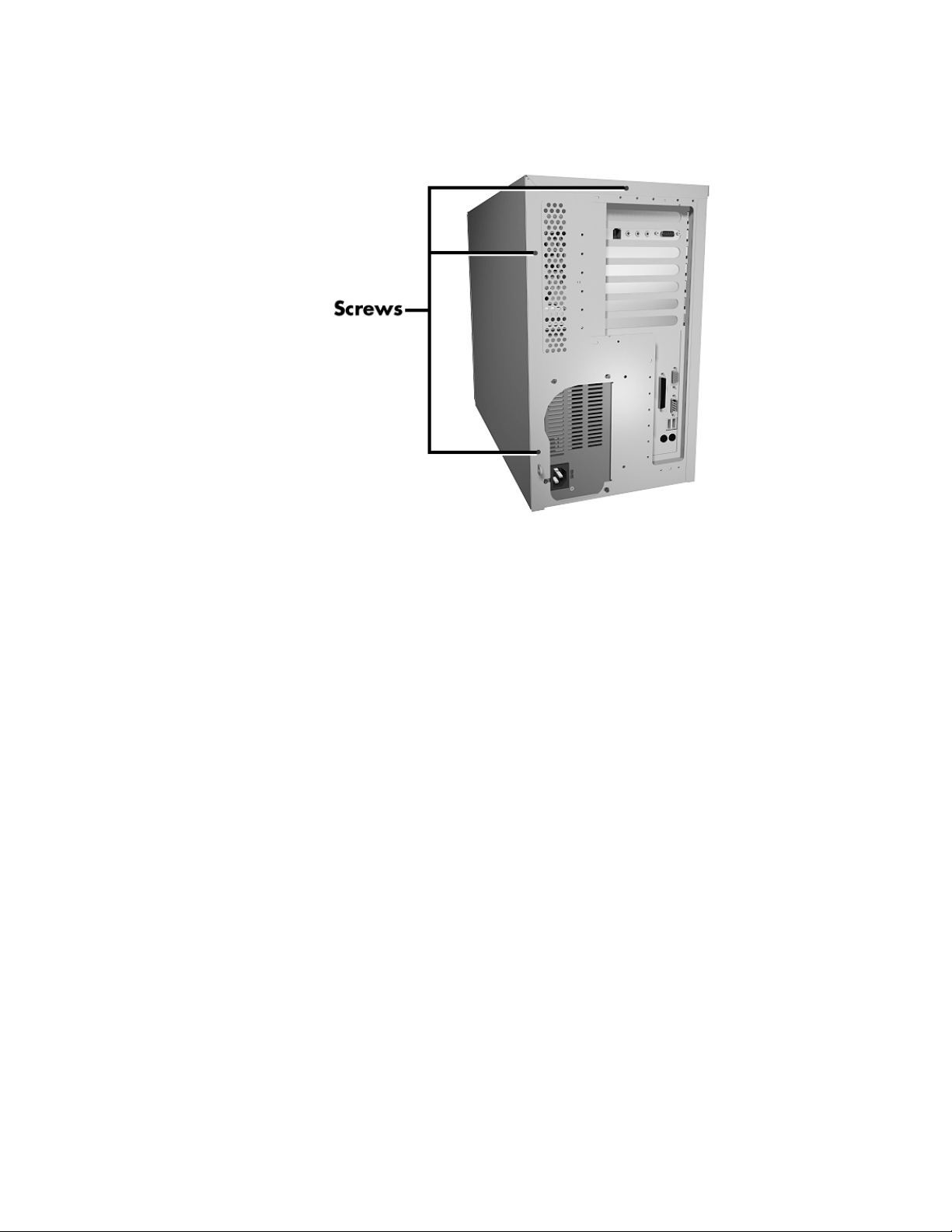
4.
Remove the three cover screws from the back of the system
unit.
Removing cover screws
A look inside 9
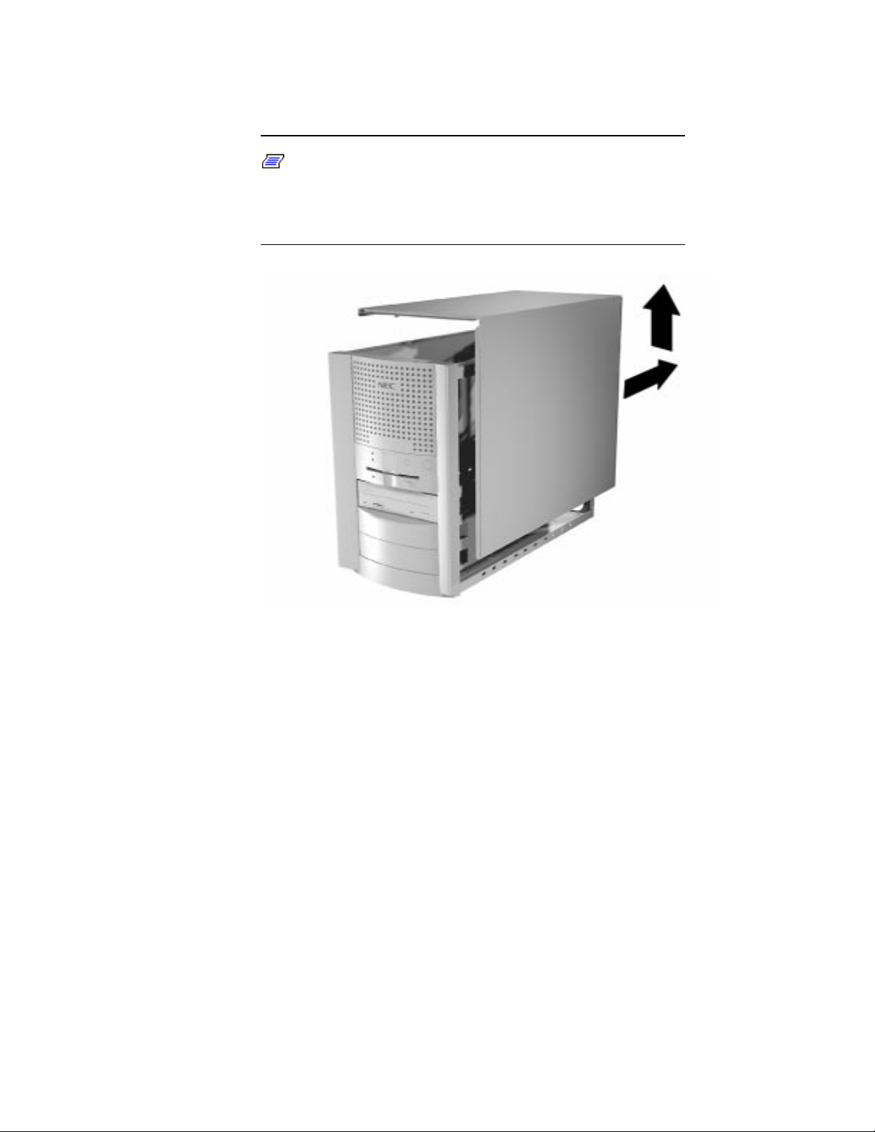
5.
Release the cover by pulling it about an inch away from the
front panel.
Note:
the front edge of the cover to release it from the front panel.
Also try pressing your thumbs against the rear panel to
slide the cover one inch away from the front panel.
The cover fits tightly. You might need to press
10 A look inside
6.
Lift the cover up and away from the system unit.
Releasing the cover
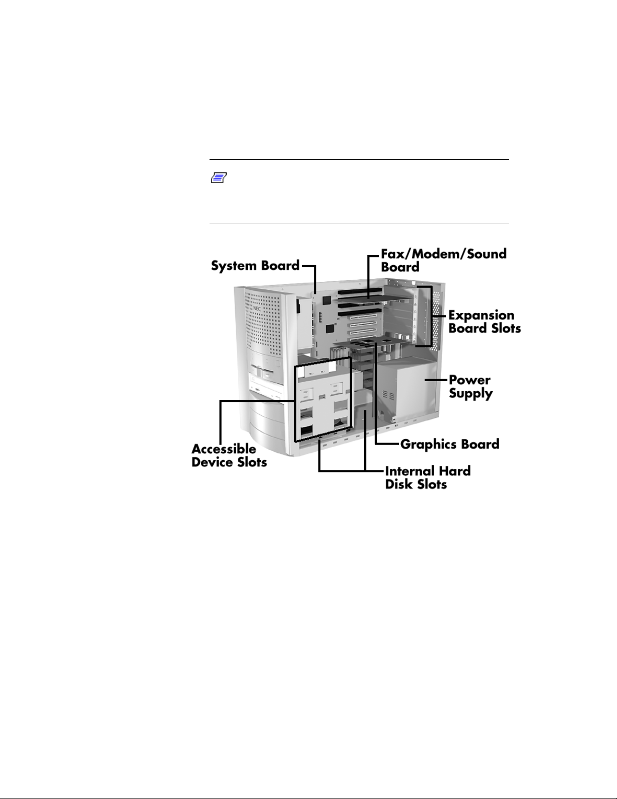
Taking a quick look inside
Take a quick look at the following figure to become familiar with the
features in your system unit. Some systems ship with a graphics
board, fax/modem/sound board, or Ethernet network board (not
shown), depending on system configuration.
Note:
to view them in color, see “System Upgrades” in your NEC
Help Center. Then choose “Looking at Your System.”
For a detailed description of these features and
Inside your system unit
A look inside 11
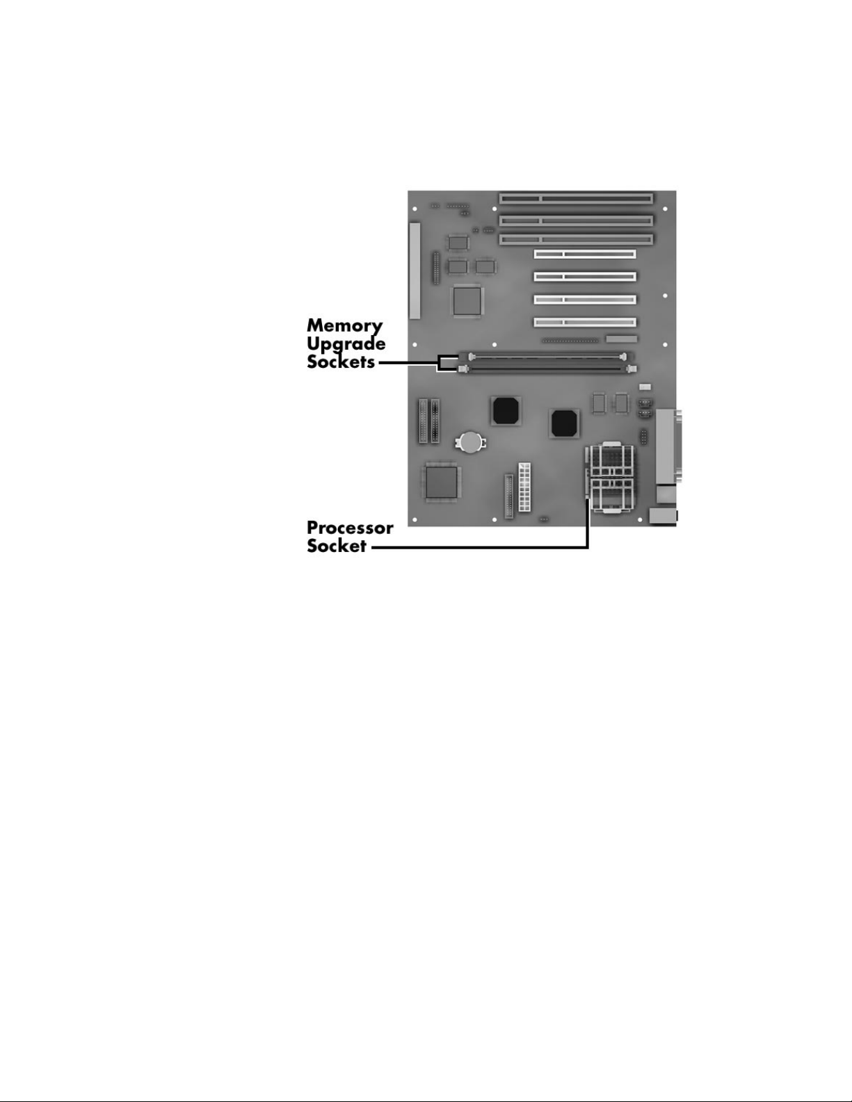
Looking at the system board
See the following figure to locate the memory and processor upgrade
sockets on your system board.
12 A look inside
System board upgrade sockets
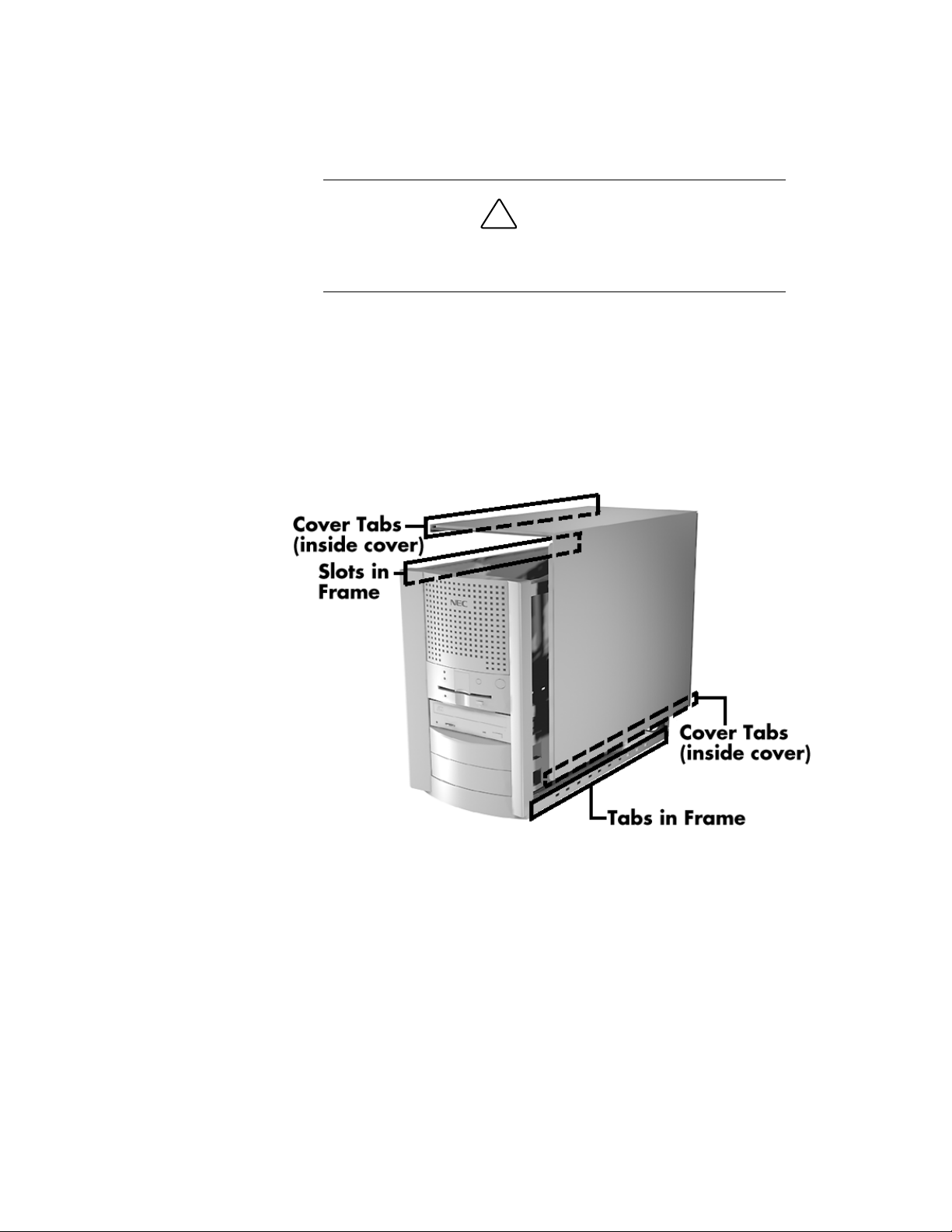
Replacing the cover
Use the following steps to replace the system unit cover.
To prevent damage to the system cables, carefully tuck the
cables out of the path of the cover.
1.
With the cover about an inch away from the front of the
system unit, carefully align the top and bottom cover tabs into
the slots and tabs in the system unit frame.
Be sure that the cover tabs on the sides of the cover align
inside the frame of the unit.
!
CAUTION
Aligning the cover
A look inside 13

2.
Slide the cover forward to meet the front panel.
Note:
all the way to the front panel, place one hand on the front
of the unit while you slide the cover forward from the rear.
3.
Secure the cover with the three cover screws removed earlier
The cover fits tightly. If the cover does not slide
(see “Taking off the cover”).
4.
If you have a cover lock, replace it and secure it.
5.
Connect the monitor, keyboard, mouse, and any other external
devices to the back of the system unit.
6.
Plug in your power cables.
14 A look inside

System memory
See the following sections for information about:
the memory upgrade kits for your computer
how to identify the memory in your system
where to install additional memory
how to add memory.
System memory 15

Looking at memory upgrade kits
Memory upgrade kits are installed in two memory upgrade sockets on
the system board. Your system board ships with 32 MB of high-speed
memory and supports up to 128 MB of memory.
Note:
modules referred to in the computer industry as “dual in-line
memory modules” or “DIMM” sticks.
Your system supports the following 60-ns 64-bit (non-parity)
synchronous dynamic random access memory (SDRAM)
configurations:
1-MB by 64-bit DIMM stick (4-MB module)
2-MB by 64-bit DIMM stick (8-MB module)
Memory upgrade kits for your computer contain
To avoid corrosion between different metals, only use
memory modules with gold-plated connectors.
16 System memory
4-MB by 64-bit DIMM stick (16-MB module)
8-MB by 64-bit DIMM stick (32-MB module)
16-MB by 64-bit DIMM stick (64-MB module).
!
CAUTION

Checking the memory in your system
Use the following procedure to:
check the memory installed in your system
determine the memory configuration you need to increase
your memory
identify the correct sockets for the memory upgrade.
1.
If you don’t know how much memory is installed in your
system, you can check the amount in Windows® 95. On the
Windows 95 desktop, point to My Computer and click the
right mouse button.
With the left mouse button, click Properties. The General tab
shows the random access memory (RAM). This is the amount
of system memory in your computer.
You can also find the amount of memory by selecting the
Performance tab.
2.
Remove the system unit cover (see “Taking off the cover”).
!
Be sure that the system unit power is
system is
procedure.
unplugged
WARNING
turned off
before you begin the installation
System memory 17
and the
3.
Determine the amount of memory you want to add and the
modules you need. Modules do not need to be added in pairs.
You may add modules singly.
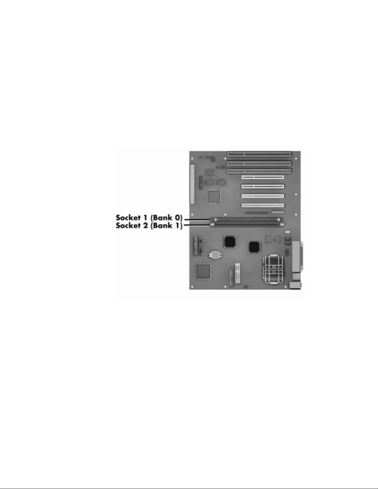
4.
Use the following figure to locate and identify the memory
upgrade sockets for the installation.
If any cables block access to the sockets, label the cables and
disconnect them.
If any expansion boards block access to the sockets, remove
the expansion boards (see “Expansion boards”).
18 System memory
Identifying the memory sockets
Adding memory modules
Use the following steps to install memory modules.
1.
Remove the system unit cover (see “Taking off the cover”).
!
Be sure that the system unit power is
system is
procedure.
2.
Locate the memory upgrade sockets for your configuration
(see “Checking the memory in your system”).
If you need to remove a memory module, see “Removing a
memory module” in this guide.
unplugged
before you begin the installation
WARNING
turned off
and the
!
Before you install a memory module, reduce static
discharge by touching the system’s metal chassis.
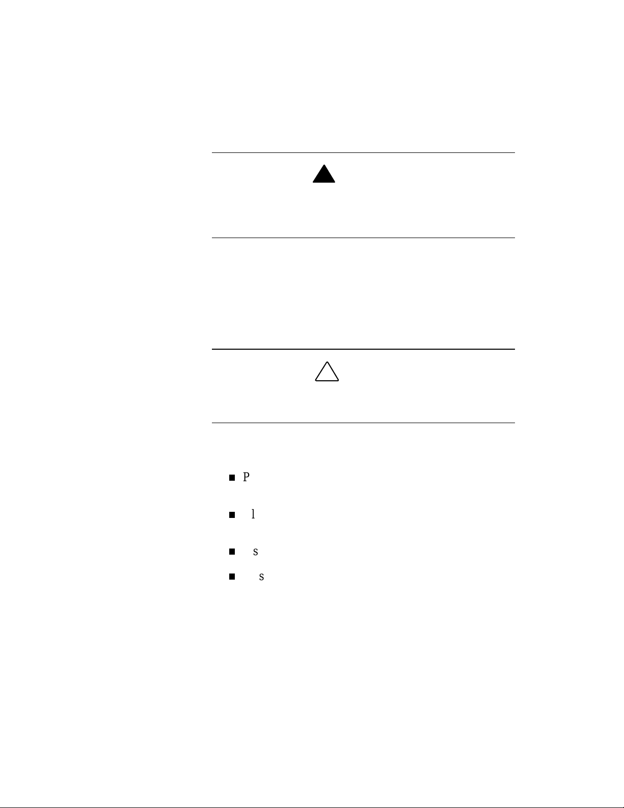
3.
Insert the memory module as follows:
Press out the plastic locking clips at the ends of an empty
socket.
Align the notches on the module with the keys in the
memory socket.
Insert the module into the socket.
Press in the plastic locking clips at the ends of the socket
until they lock in place on the module.
CAUTION
System memory 19
!
Be careful when handling the memory module. The module
and socket clips are fragile.
4.
Replace any cables or boards that you removed during this
procedure (see “Expansion boards”).
CAUTION
Inserting the module
5.
Note: If you find a discrepancy in the amount of
memory displayed at the Power-On Self-Test with the
amount of memory that you installed, check that you
installed the memory modules correctly.
20 System memory
Replace the system unit cover (see “Replacing the cover”).
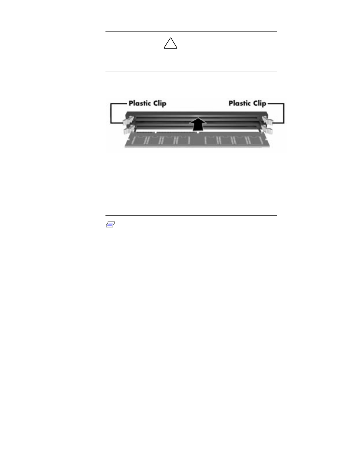
Removing a memory module
If your memory configuration requires the removal of a module,
remove the module as follows.
!
To reduce static discharge, touch the system’s metal
chassis.
1.
Press the plastic locking clips at the ends of the socket away
from the memory module.
2.
Gently rock the memory module while pulling it up from the
socket.
CAUTION
Removing a module
System memory 21

Expansion boards
You’ll find information in the following sections about:
how to add a board to your computer
how to remove a board from your computer.
Note:
is in the way of adding other options or connecting cables.
See the board removal procedure when a board
Expansion boards 23

Adding boards
Use the following steps to add a board to your system unit.
Be sure that the system unit power is
system is
procedure
1.
Follow any preinstallation instructions that come with your
expansion board (such as setting switches or jumpers on the
board).
2.
See the information that comes with your board to determine
which type of board you have:
an 8-bit or 16-bit Industry Standard Architecture (ISA)
board
!
unplugged
.
WARNING
turned off
before you begin the installation
and the
3.
Remove the system unit cover (see “Taking off the cover”).
24 Expansion boards
a 32-bit Peripheral Component Interconnect (PCI)
board.

4.
Locate the appropriate ISA or PCI slot for your board.
Locating a slot for your board
Expansion boards 25

5.
Remove the screw securing an expansion slot cover and
remove the cover. Save the screw for installing the board.
Store the slot cover in case you choose to remove the board in
the future.
The following figure shows boards removed for clarity.
26 Expansion boards
Removing a slot cover

6.
Hold the board by its edges and install it into the slot:
If you have a full-width board, align it with the guide rail at
the front of the system unit.
Align the connector end of the board with the slot
connector.
Press the board firmly into the slot connector. You might
have to gently rock the board from side-to-side to seat it
into the connector.
Insert the screw you removed earlier to secure the board to
the support bracket.
Inserting a board
Expansion boards 27

7.
Replace the system unit cover (see “Replacing the cover”).
8.
Add any necessary drivers. See the instructions that come
with the board for information about driver requirements.
Removing a board
See the following steps to remove a board from your system unit.
Be sure that the system unit power is
system is
procedure
1.
Remove the system unit cover (see “Taking off the cover”).
2.
If you have any cables connected to the board that you need
to remove, label the cable.
unplugged
.
!
WARNING
turned off
before you begin the removal
and the
On the label, write or draw the following cable information:
Then disconnect the cable from the board.
28 Expansion boards
Location of the connector on the board.
Note the cable connector alignment. Look for a colored
edge of the cable and notice whether it is on the right, left,
top, or bottom side of the board connector.

3.
Remove the screw that secures the board to the support
bracket (see the following figure).
4.
Pull the board out of the connector. You might have to gently
rock the board from side-to-side to release it from its
connector.
Removing a board
5.
Replace the system unit cover (see “Replacing the cover”).
Expansion boards 29

System processor
See the following sections for information about:
removing the processor in your computer
adding an upgrade processor, such as an Intel
OverDrive™ processor.
®
System processor 31

Removing the processor
To upgrade your processor, you must first remove the processor
currently in your computer. Use the following steps to remove it.
1.
Remove the system unit cover (see “Taking off the cover”).
!
Be sure that the system unit power is
system is
procedure.
2.
Locate the processor socket on the system board (see
“Looking at the system board”).
If you have expansion boards obstructing your view of the
socket, remove them (see “Removing a board”).
unplugged
before you begin the installation
WARNING
turned off
and the
If the power supply is obstructing your access to the
processor socket, remove it (see step 3). Check “Taking a
quick look inside” for the location of the power supply.
32 System processor

3.
Remove the power supply to access the processor socket.
At the back of the system unit, locate and remove the four
power supply screws.
Carefully lift the power supply out of the system unit. You
might need to label and disconnect any cables that do not
reach outside the unit.
Locating the power supply screws
System processor 33

4.
Release the heatsink clamp from the socket tabs.
5.
Release the processor by pulling the socket lever away from
the socket and as far back as it can go without forcing.
Before you pick up the processor, reduce static discharge
by touching the metal frame of the chassis.
6.
Lift the processor out of the socket.
34 System processor
Releasing the heatsink clamp
!
CAUTION
Adding a processor
Use the following steps to add a processor upgrade to your computer.
1.
Remove the processor currently in your system (see
“Removing the processor”).
Before you pick up the processor, reduce static discharge
by touching the metal frame of the chassis.
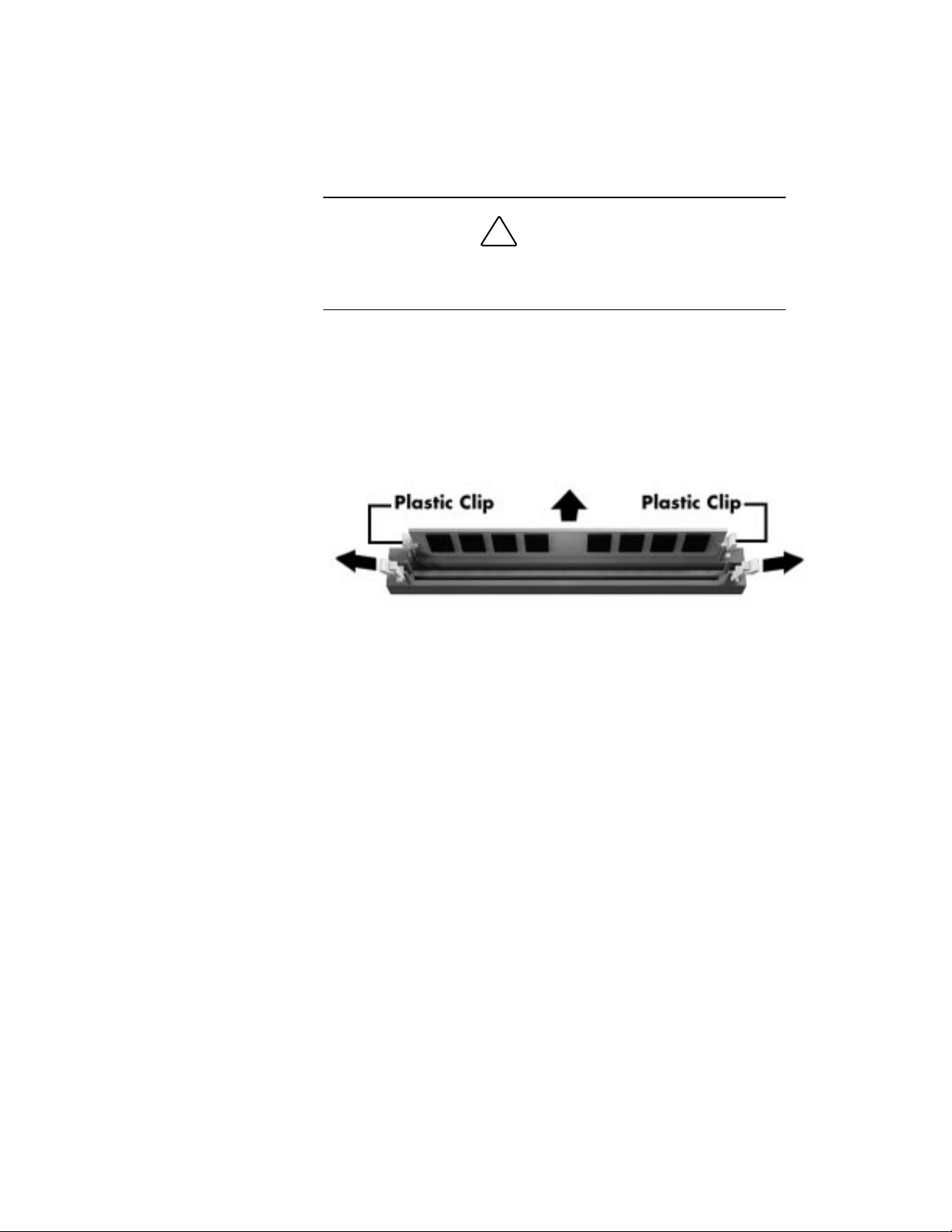
2.
Align the notched corner of the processor with the pin 1
corner of the socket. Insert the processor into the socket.
!
CAUTION
Aligning the processor with the socket
System processor 35

3.
Swing the socket lever down to lock the processor in the
socket.
4.
Replace the heatsink by positioning the clamp openings over
the socket tabs.
5.
Be sure your jumper settings are set correctly for your
upgrade processor (see “Checking jumper settings” in the
“System Resources” section of this guide).
36 System processor
Replacing the heatsink

6.
Replace the power supply you removed during this procedure.
If you disconnected any cables from the power supply,
reconnect them.
Secure the power supply with the four screws you removed
earlier.
7.
Replace any expansion boards you might have removed during
this procedure (see “Adding a board”).
8.
Replace the system unit cover (see “Replacing the cover”).
System processor 37

Storage devices
Your Ready computer holds up to six storage devices. For a
description of which devices you have and what you can add, go to
your online NEC Help Center and select “System Upgrades.” Select
“Adding Upgrade Options” and choose “Data Storage Devices.”
If you’re ready to add an option, see the following sections:
preparing your device for installation
identifying the cables you need
connecting the cables to your device
installing storage devices.
Storage devices 39

Preparing the device
Before you install a storage device in your computer, follow any
preinstallation instructions that come with the device.
For example:
Diskette drive — remove any termination on an optional
diskette drive. See the documentation that comes with the
drive.
IDE device — check the jumper settings on an IDE device
before you install it. See the documentation that comes with
the device for jumper setting information.
If you have an IDE device, you need to know which of the two IDE
connectors, primary or secondary, you are going to use to add your
device. Here’s some information about the IDE connection:
An IDE device, such as an IDE hard disk or IDE CD-ROM
reader, must be set correctly as the first (master) or second
(slave) device on the primary or secondary IDE connector on
the system board.
The IDE hard disk that comes with your system is set as the master
device on the high-speed primary IDE connector. The CD-ROM
reader that comes with your system is set as the master device on the
secondary IDE connector. Any optional IDE device that you install
must be set as the slave device on the primary or secondary IDE
connector.
See “IDE cables” in the next section for more information about IDE
connections.
40 Storage devices
One master device and one slave device are supported on the
primary IDE connector, and one master and one slave device
are supported on the secondary IDE connector.
Identifying the cables you need
The cables that you use to add storage devices in your system
include:
diskette drive cable
IDE interface cable
system power cable.
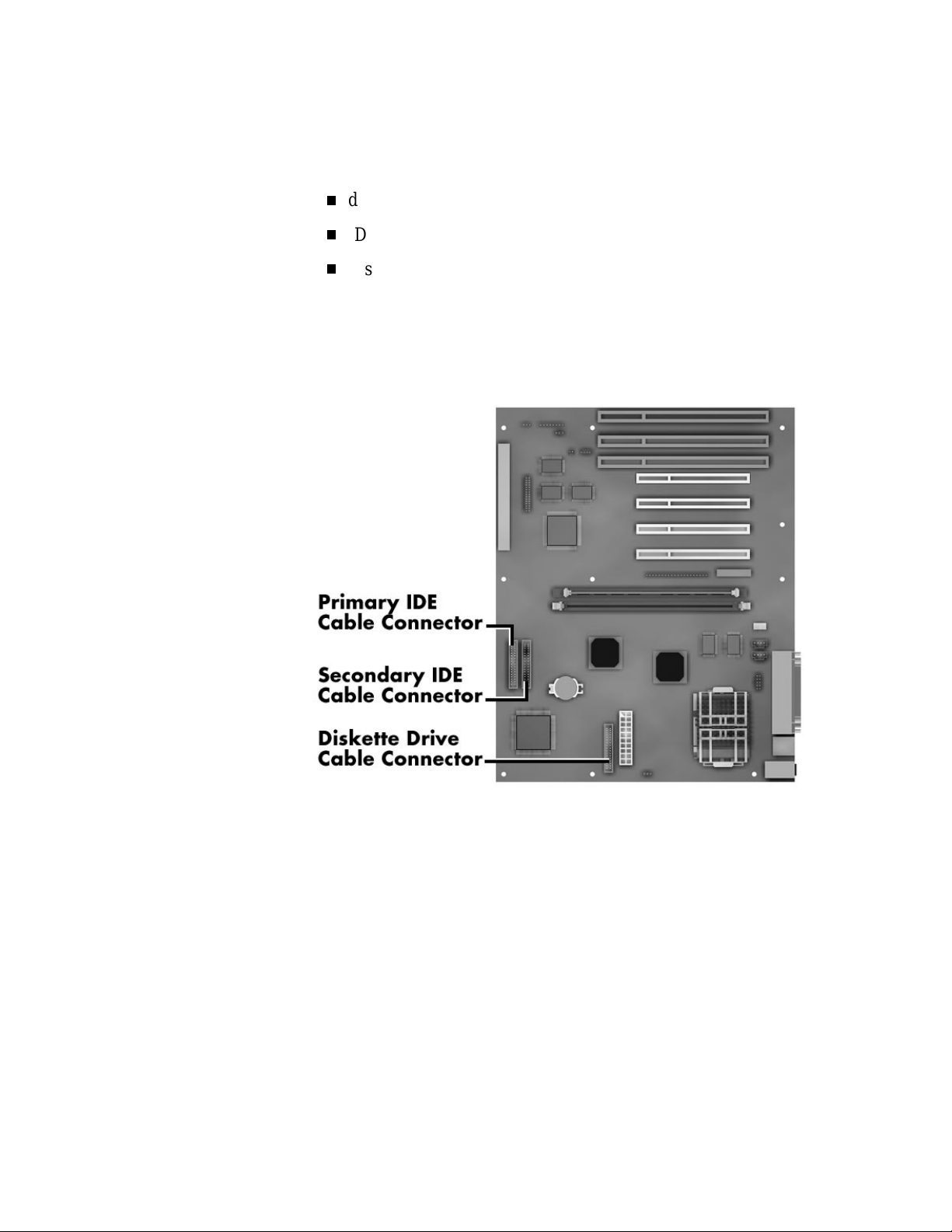
The following figure shows the cable connector locations on the
system board. See the information following the figure for
descriptions of the cables and connectors.
System board cable connectors
Storage devices 41

System power cables
Power cables come from the power supply and are attached to the
standard storage devices (hard disk, diskette drive, and CD-ROM
reader). Additional cables are available for optional devices.
System power cables vary in length and provide connector sizes to
accommodate a variety of supported storage configurations.
Power cable connectors are keyed to fit only in the correct position.
42 Storage devices
Power cable connectors

Diskette drive cable
A three-connector diskette drive signal cable comes attached to the
system board and to the standard 1.44-MB diskette drive.
The cable connector for a 5 1/4-inch diskette drive is keyed to fit only
in the correct position. The colored edge of the cable goes to pin 1 on
the cable connector. Align the red edge of the cable with pin 1 (the
notched end) on the drive connector.
Align the colored edge of the cable with the pin 1 side of the system
board diskette drive cable connector.
Three-connector diskette drive signal cable
Storage devices 43
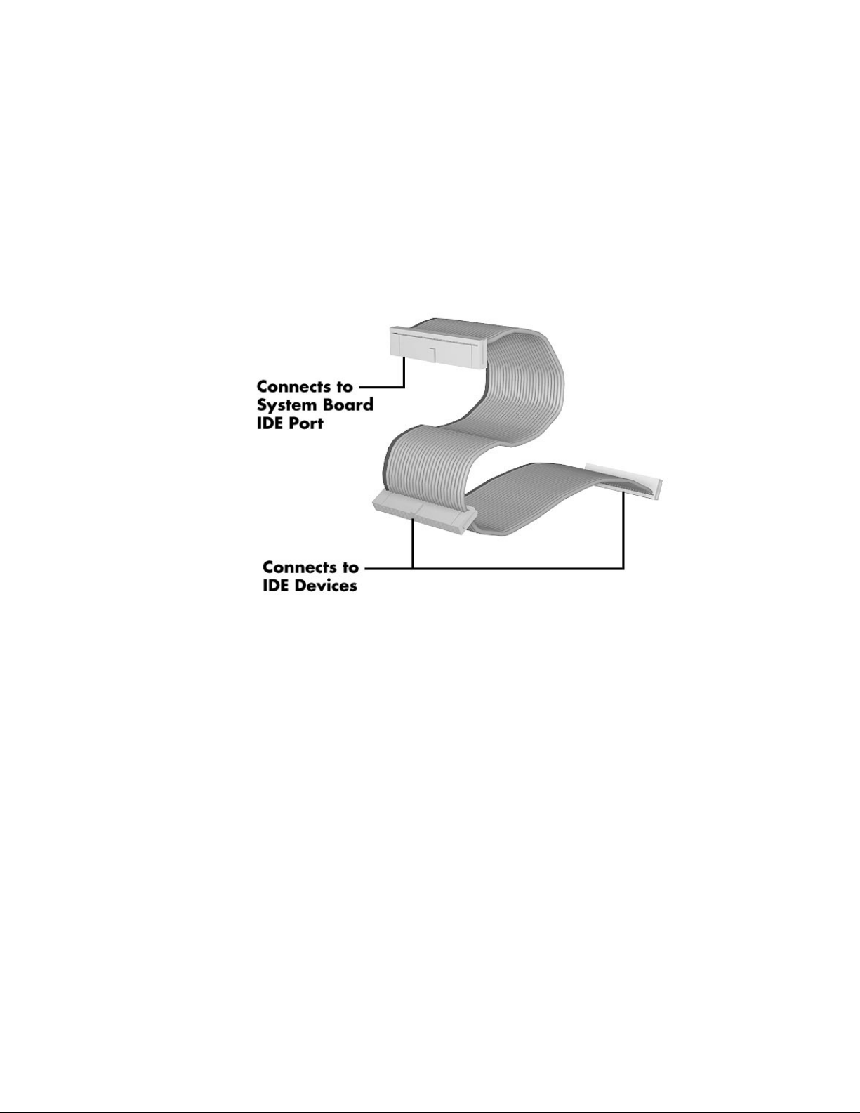
IDE cables
Your system comes with a three-connector IDE interface cable
attached to the standard hard disk and to the primary IDE connector
on the system board. A second three-connector IDE cable connects to
the standard CD-ROM reader and to the secondary IDE connector.
Each IDE connector on the system board supports two IDE devices.
The following figure shows a typical three-connector IDE cable.
If your IDE cable is not keyed with a connector tab, align the colored
edge of the cable with the pin 1 side of the drive connector and
system board IDE connector.
44 Storage devices
Three-connector IDE drive signal cable

Connecting cables to your device
All storage devices require a power cable and a signal cable
connection. The devices that come with your system are already
connected.
Use the information in the following section along with the
appropriate procedure in “Installing storage devices” to install
optional devices. Refer to the appropriate section to cable your
device:
“Cabling an IDE device”
“Cabling a diskette drive.”
Cabling an IDE device
Use the following steps to cable an IDE device such as an IDE hard
disk or CD-ROM reader.
1.
Connect the unused connector on the installed IDE cable (see
“IDE cable”) to the IDE device.
Take care to prevent bending drive connector pins. Align the
IDE cable connector as shown in the following figure.
Storage devices 45
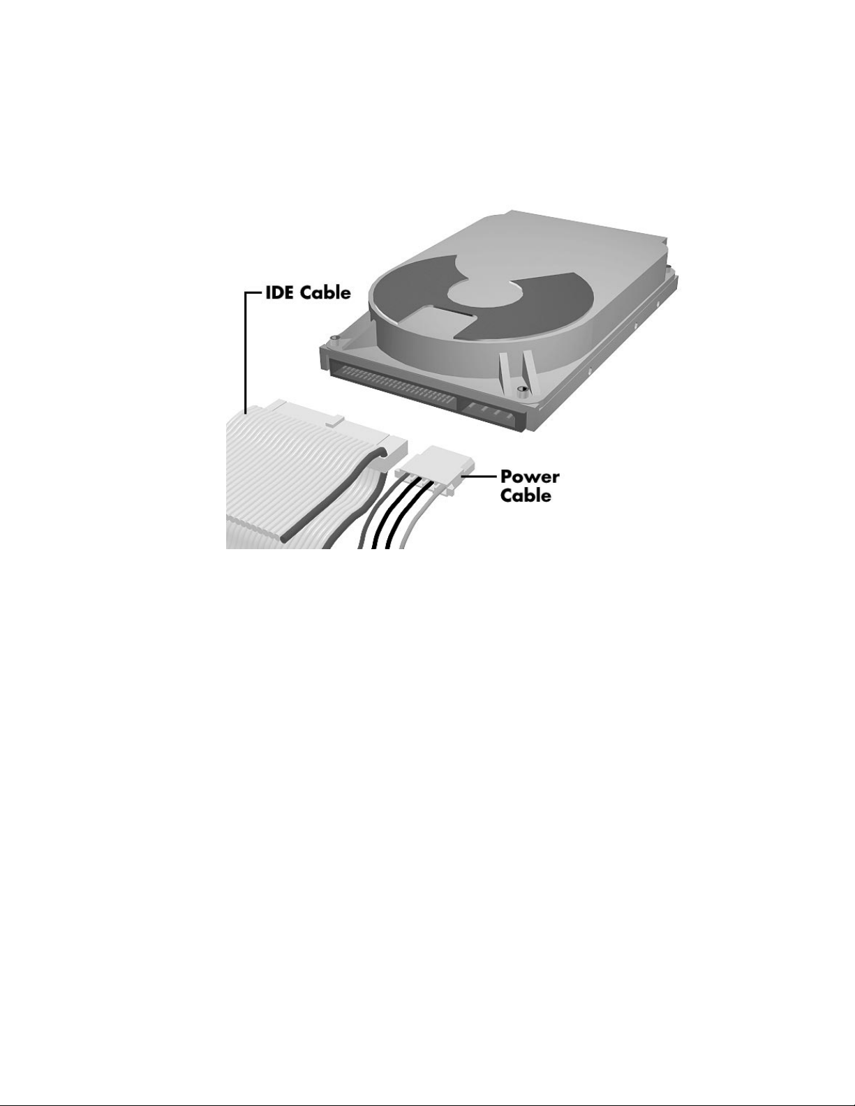
2.
Locate an available power connector coming from the power
supply (see “System power cables”).
Connect the power cable to the power connector on the IDE
device (see the following figure).
3.
46 Storage devices
Connecting cables to an IDE device
If you are installing a CD-ROM reader, also connect the audio
cable (see the instructions that come with the reader).
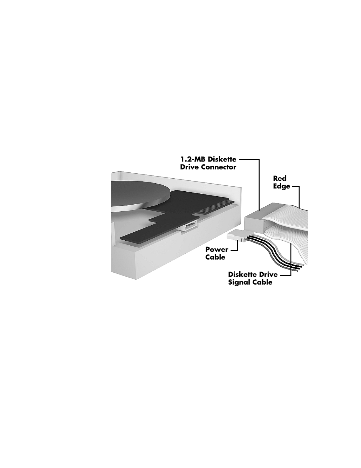
Cabling a diskette drive
Use these steps to cable a second diskette drive, such as a 1.2-MB
diskette drive.
1.
Connect the appropriate diskette drive cable (see “Diskette
drive cable”) to the diskette drive.
2.
Locate an available power connector coming from the power
supply (see “System power cables”).
3.
Connect the power cable to the power connector on the
diskette drive.
Connecting cables to a diskette drive
Storage devices 47

Installing storage devices
Your Ready computer comes with one free 3 1/2-inch device slot and
two free 5 1/4-inch device slots. See the following procedures to add
your storage device:
“Adding a 3 1/2-inch hard disk”
“Adding a 5 1/4-inch device.”
Adding a 3 1/2-inch hard disk
Use the following steps to add a 3 1/2-inch hard disk to your system.
1.
Follow the preinstallation instructions that come with your
device, such as setting jumpers and switches.
See “Preparing your device” earlier in this guide for
preparation information.
2.
Be sure that the system power is
peripherals are
installation procedure.
48 Storage devices
Be sure you have handy the four screws that come with the
hard disk.
Remove the system unit cover (see “Taking off the cover”).
!
unplugged
WARNING
off
and the system and its
before you begin the

3.
Locate the following items inside your computer (see “Taking
a quick look inside”):
standard hard disk installed in the front 3 1/2-inch slot
CD-ROM reader
power supply
internal 3 1/2-inch drive slot (next to the power supply).
4.
To access the internal drive slot, remove the power supply
from the inside of the unit as follows:
At the back of the system, locate and remove the four
power supply screws.
Locating the power supply screws
Storage devices 49

Carefully lift the power supply out of the system unit. You
might need to label and disconnect any cables that do not
reach outside the unit.
5.
Connect the IDE and power cables to the new hard disk as
follows:
Carefully place the system unit on its side with the open
side facing up.
Locate the four holes on the bottom of the hard disk.
Hold the hard disk with the holes facing the floor of the
system unit and the connectors facing the front of the unit.
Connect the IDE and power cables to the hard disk (see
“IDE cables”).
6.
Install the hard disk in the drive slot as follows:
50 Storage devices
Locate the four holes on the bottom of the system unit (see
the following figure).
Position the hard disk in the hard disk drive slot area (see
“Taking a quick look inside”).
Align the four holes on the bottom of the hard disk with
the holes in the drive slot (see the following figure).
Secure the hard disk with the four screws that come with
the hard disk.

Securing the hard disk
7.
Carefully lift the system unit back into its upright position.
Replace the system unit cover (see “Replacing the cover”).
8.
Replace the power supply in the system unit. If you
disconnected any cables, reconnect them. Secure the power
supply with the four screws you removed earlier.
9.
Run the Setup utility to set your new configuration. See
“Setup Utility” in the “Advanced Topics” category of your
NEC Help Center.
This completes your 3 1/2-inch device installation!
Storage devices 51

Adding a 5 1/4-inch device
Use the following steps to add a 5 1/4-inch device into an accessible
device slot in your system.
1.
Follow the preinstallation instructions that come with your
device, such as setting jumpers and switches.
See “Preparing your device” earlier in this guide for
preparation information.
Note:
do not attach them. Remove any rails already attached.
See the documentation that comes with the device.
2.
Remove the system unit cover (see “Taking off the cover”).
If your 5 1/4-inch device comes with drive rails,
Be sure that the system power is
peripherals are
installation procedure.
3.
plugs.
52 Storage devices
!
unplugged
Remove the front panel by carefully pulling it off the front of
the system unit. Use an even amount of pressure around the
edges of the panel.
Note:
The front panel is secured with six locking
WARNING
off
and the system and its
before you begin the
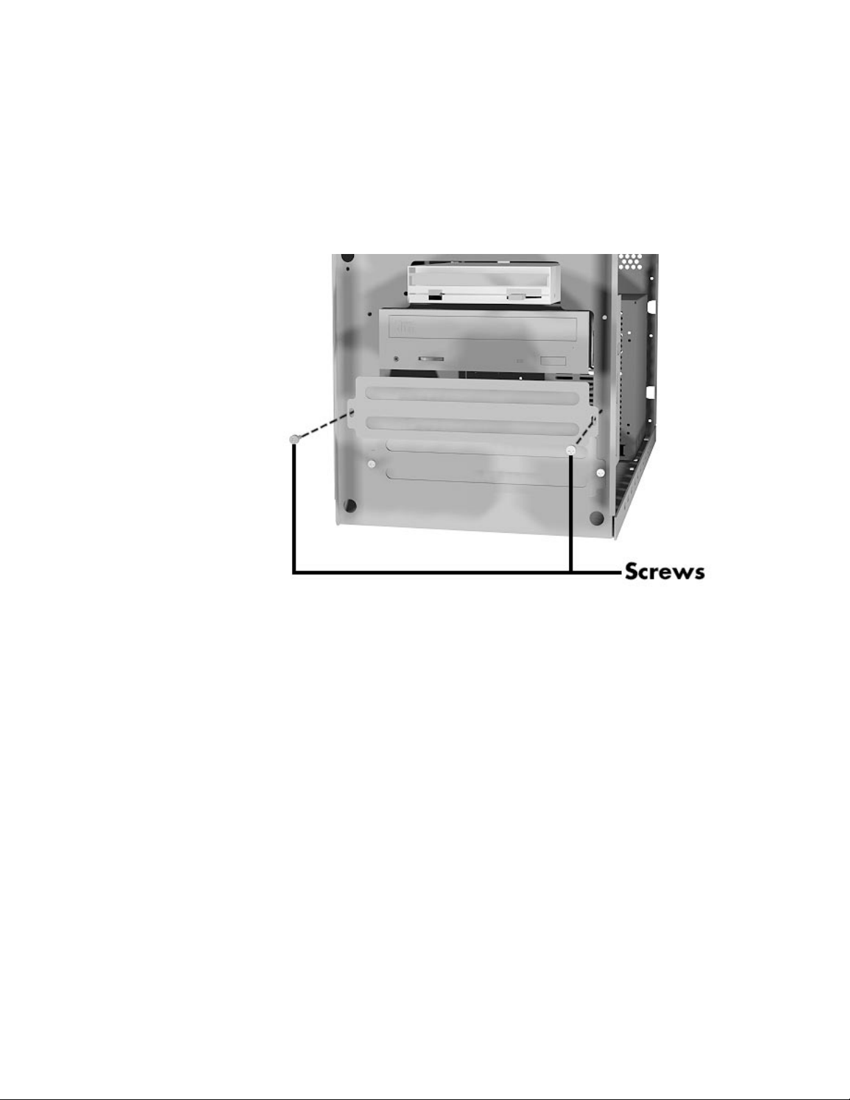
4.
Remove the two screws holding the slot cover and the two
rails to a device slot in the system.
If you are installing a hard disk in the 5 1/4-inch slot, keep the
slot cover handy.
Otherwise, store the slot cover. Replace the cover if you
remove the device from the slot.
Removing a slot cover
Storage devices 53

5.
Attach the two rails that come with your system to the sides
of the device. Use the four screws that come with the device.
If you are installing an accessible device, attach the rails to
the device so that the front of the device extends outside
the chassis.
The front of a typical device should be even with the blank
panels on the front of the system.
54 Storage devices
Attaching the rails

6.
If you are installing an accessible device, locate the blank
panel on the front panel corresponding to the device slot in
the system.
Remove the blank panel by pressing the panel tabs from inside
the panel and pushing the panel out.
Locating the blank panel tabs
Storage devices 55
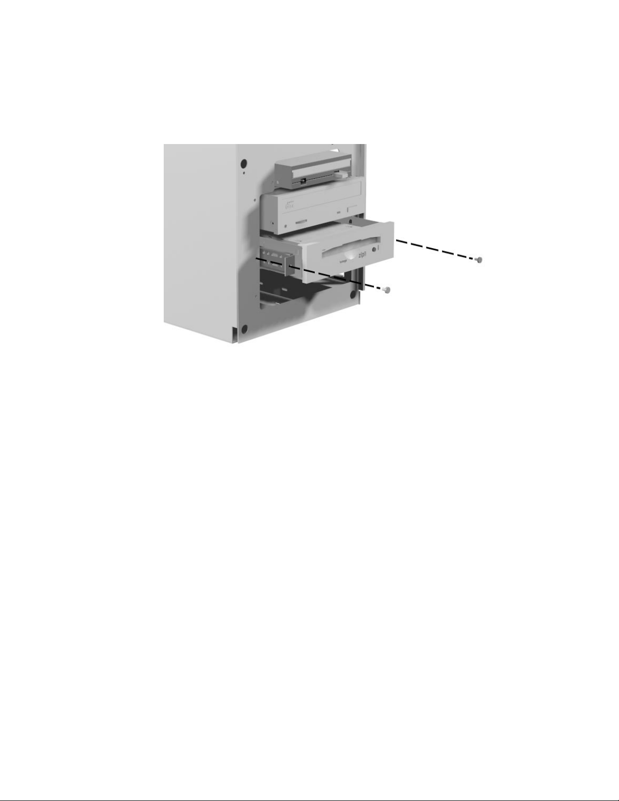
7.
Insert the connector end of the device into the device slot in
the system unit.
Secure the device with the two slot cover screws you
removed earlier.
8.
56 Storage devices
Securing the device
Connect the device cables (see “Identifying the cables you
need”).

9.
Replace the front panel:
Align the front panel plugs with the system unit holes.
Press the front panel onto the front of the system unit to
secure it.
Replacing the front panel
10.
Replace the system unit cover (see “Replacing the cover”).
11.
Run the Setup program to set your new configuration (see
“Setup Utility” in the “Advanced Topics” category of your
NEC Help Center).
This completes your 5 1/4-inch device installation!
Storage devices 57

External options
The previous sections describe adding options to the inside of your
Ready computer. You can also expand the capabilities of your
computer by adding options to the outside of the computer.
See the following sections to:
locate the external connectors on your computer
connect an NEC CS500™ monitor
connect an NEC C700™ monitor
connect a printer.
External options 59

Locating external connectors
Connectors on the back of your Ready computer let you add a variety
of popular industry-standard options. Depending on system
configuration, your system has either a fax/modem/sound board
(modem configuration) or a Ethernet network board and graphics
board (Ethernet configuration). See the following figures to locate the
connector for your device.
For a description of the devices each connector supports, go to
“System Tour” in your NEC Help Center. Then choose “A Closer
Look at the Parts” and “Looking at the Back.”
Locating your external device connectors (modem configurations)
60 External options
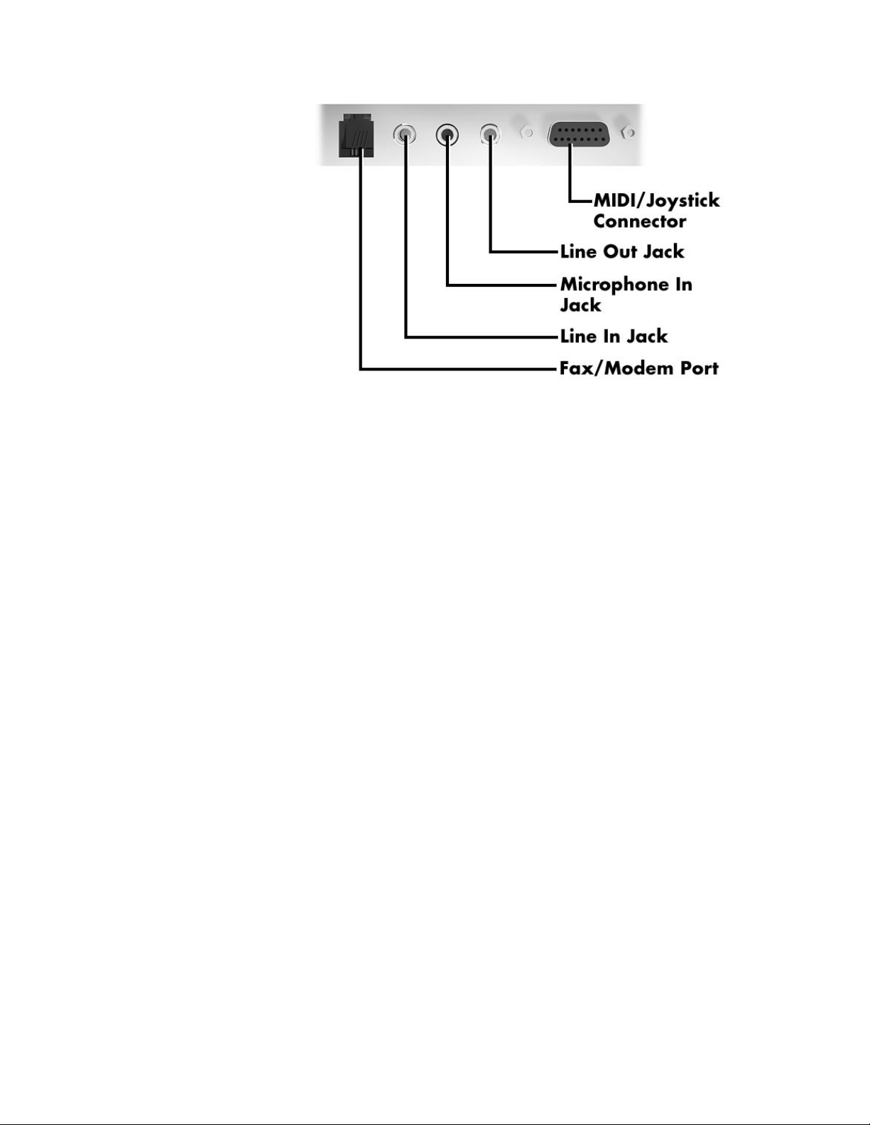
Locating your modem and audio connectors (modem configurations)
External options 61

Locating your external device connectors (Ethernet configurations)
62 External options
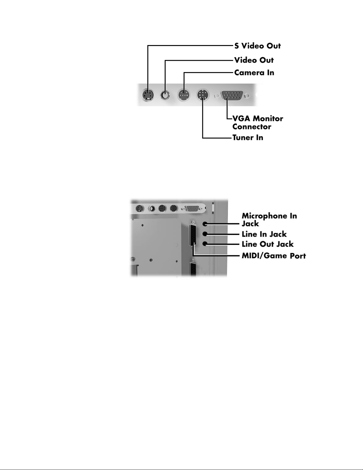
Locating your graphics board connectors (Ethernet configurations)
Locating your audio connectors (Ethernet configurations)
External options 63
Connecting an NEC CS500 monitor
Some systems ship with the NEC CS500 monitor. The monitor
integrates in one cabinet an NEC color monitor, two amplified
speakers, and a microphone.
If your system comes with the NEC CS500 monitor, use the
following steps to connect the monitor to the back of your system
unit. Also see the documentation that comes with the monitor.
1.
Turn off and unplug the system unit and any external options
connected to the system unit.
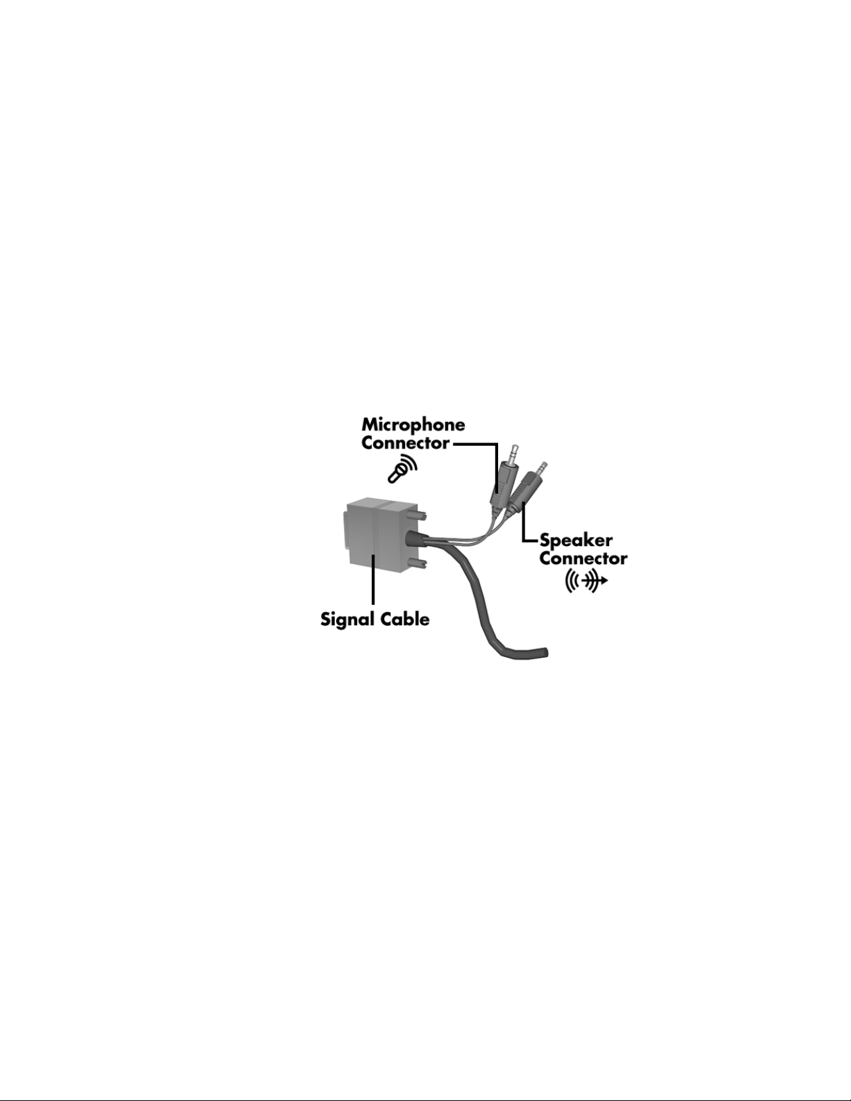
2.
Locate the signal cable connector, microphone connector, and
speaker connector on the monitor cable.
64 External options
Identifying the NEC CS500 monitor cable connectors

3.
Connect the monitor signal cable to the VGA monitor
connector on the back of your system unit. Secure the
connector with the screws provided.
Note:
connectors on the back of the system unit vary, depending
on system configuratio n. See the preced ing figures for the
location of the connectors.
4.
Connect the microphone cable to the microphone in jack.
5.
Connect the speaker cable connector to the line out jack.
6.
Connect one end of the power cable to the monitor and the
The location of the monitor connector and audio
other end to a properly grounded power outlet.
Connecting the NEC CS500 monitor power cable
External options 65

7.
Reconnect the system unit power cable and any external
option power cables to the system unit.
8.
Press the power button on the front of the monitor.
9.
Press the power button on the front of the system unit.
See the monitor’s documentation for further information on using the
monitor with your system.
Connecting an NEC C700 monitor
Some systems ship with an NEC C700 monitor, without speakers and
microphone. You might want to add optional speakers and an
optional microphone.
Follow these general steps to connect the monitor and any optional
components. Also see the documentation that comes with the units
for detailed connection information.
connectors on the back of the system unit vary, depending
on system configuratio n. See the preced ing figures for the
location of the connectors.
1.
2.
3.
66 External options
Note:
The location of the monitor connector and audio
Turn off and unplug your system unit and any external options
connected to the system unit.
Connect the monitor signal cable to the VGA monitor
connector on the back of your system unit. Secure the
connector with the screws provided.
Connect the optional microphone to the microphone jack on
the back of your system unit.

4.
Connect the optional speaker set. See the documentation that
comes with the speakers for additional connection
information.
Connect the speakers.
Connect the speaker-to-system cable to the line out jack on
the back of your system unit.
If your speaker set has an AC adapter, connect the adapter
to the speaker and to a grounded power source.
5.
Connect the monitor power cable, system unit power cable,
and any external option power cables to a grounded power
source.
See the monitor’s documentation for further information on using the
monitor with your system.
External options 67

Connecting a printer
Before you connect a printer to your computer, follow the setup
instructions that come with the printer. Then follow these steps:
1.
Turn off and unplug the system unit and any external option
connected to the system unit.
2.
Check that the printer power is off and the power cable is
unplugged.
3.
Connect the printer cable to the printer port on the rear of the
system unit. Secure the system connection with the screws
provided.
4.
68 External options
Connecting a printer cable
Connect the printer cable to the printer. Secure the cable with
the clips on the printer connector.

5.
See the NEC Help Center for setting up a printer in
Windows® 95.
If your printer is not included in the Windows 95 listing, see your
printer manual or call the printer manufacturer.
External options 69

System resources
When you are setting up new hardware, your system might require
information such as available system resources. The following
sections include information about:
system resources for your communications ports
default system settings
viewing system resources
jumper settings on the system board.
System resources 71

Looking at communication ports
Your system’s communications ports include a fax/modem port or
network port (depending on your system configuration) and a serial
port.
Communication port settings are listed below.
Fax/modem or network — enabled.
Serial port 2 — enabled as serial port.
See the following sections for default system settings, interrupts, and
information to view system resources.
Looking at COM port and IRQ settings
The following settings are the default COM port and IRQ settings:
Fax/modem or network — on COM1 (IRQ10)
Serial port — on COM2 (IRQ3)
COM B — enabled as serial port
Windows 95 mode, MS-DOS mode, and MS-DOS box in
Windows 95
72 System resources
IRQ0 (timer)
IRQ1 (keyboard)
IRQ2 (programmable interrupt controller)
IRQ3 COM2 (serial port)
IRQ4 (available)
IRQ5 (sound)
IRQ6 (floppy disk controller)
IRQ7 (LPT1)

IRQ8 (real time clock)
IRQ9 (MIDI device)
IRQ10 (modem/network)
IRQ11 (graphics/PCI handler)
IRQ12 (mouse)
IRQ13 (coprocessor)
IRQ14 (primary IDE)
IRQ15 (secondary IDE).
See the following section to view system resources.
Viewing system resources
Some hardware option installations might require system resources
such as interrupt request (IRQ) lines, direct memory access (DMA)
channels, and input/output (I/O) addresses. See the following
procedures to view system resources.
Follow these steps to view system resources:
1.
From the Windows 95 desktop, click the “My Computer” icon
with the
2.
Click “Properties.” The System Properties box appears.
3.
Click the Device Manager tab.
4.
Double click “Computer.” The Computer Properties box
right
mouse button.
appears and displays the View Resources folder.
The View Resources folder shows the system resources used by your
computer. For example, it shows a list of interrupts and how they are
allocated. If an interrupt is not in the list, it is available.
System resources 73

Checking jumper settings
The following procedure explains how to locate and, if necessary,
change jumper settings when you upgrade your processor. See this
section to also view factory jumper settings.
If a jumper change is required, lift the plastic block from the jumper
pins with needle-nose pliers and place the block on the appropriate
pins.
!
Jumpers are set correctly at the factory for your configuration.
If your system requires a jumper change, change only the
setting for that condition. Otherwise, keep the settings at
their factory settings.
CAUTION
The system power must be off before changing a jumper
setting.
1.
Power off and unplug the system and any attached devices.
2.
Remove the system unit cover (see “Taking off the cover”
earlier in this guide).
74 System resources
!
WARNING

3.
Locate the host bus frequency jumper (J9C1-C) and processor
frequency jumper (J9C1-D) on the system board (see the
following figure).
You might need to remove any installed expansion boards to
access the jumpers (see “Removing a board”).
Locating system configuration jumpers
System resources 75

4.
Check the processor and host bus frequency jumper settings
on your system board using the following factory settings. If
upgrading your processor, set the jumpers per the following
and the instructions included with the processor.
166-MHz processor
Host PCI ISA Bus/
Bus Bus Bus Processor
J9C1-C J9C1-D
5-6 2-3, 5-6 66 MHz 33 MHz 8.33 MHz 2.5
200-MHz processor
J9C1-C J9C1-D
5-6 1-2, 5-6 66 MHz 33 MHz 8.33 MHz 3
233-MHz processor
J9C1-C J9C1-D
5-6 1-2, 4-5 66 MHz 33 MHz 8.33 MHz 3.5
Freq. Freq. Freq. Freq. Ratio
Host PCI ISA Bus/
Bus Bus Bus Processor
Freq. Freq. Freq. Freq. Ratio
Host PCI ISA Bus/
Bus Bus Bus Processor
Freq. Freq. Freq. Freq. Ratio
5.
Reinstall any removed expansion boards (see “Adding
boards”).
6.
Replace the system unit cover (see “Replacing the cover”).
7.
Connect the system and monitor power cables and any
external options.
8.
Power on the monitor and system.
76 System resources

Clearing your password
If you forgot your password, use the following procedure to clear
your current password and to set a new one.
1.
Turn off and unplug the system and any external options.
2.
Remove the system unit cover (see “Taking off the cover”).
3.
Locate the Password Clear jumper (J9C1-A) on the system
board (see the “Locating system configuration jumpers”
figure in this section).
You might have to remove any installed expansion boards to
access the jumper (see “Removing a board”).
4.
Move the jumper to the Password Clear jumper pins
(pins 2-3).
5.
Replace the system unit cover (see “Replacing the cover”).
6.
Connect the system and monitor power cables.
7.
Power on the monitor and system. The system lets you boot
your computer.
8.
Power off and unplug the system and monitor.
9.
Remove the system unit cover.
10.
Move the jumper to the Password Enabled jumper pins
(pins 1-2).
System resources 77

11.
If you removed any expansion boards, replace them (see
“Adding boards”).
12.
Replace the system unit cover.
13.
Connect the system and monitor power cables and any
external options.
14.
Power on the monitor and system.
15.
Run Setup to set a new password (see “Setting a Password”
in the “Advanced Topics” category of your NEC Help
Center).
78 System resources

System specifications
Look through these specifications for information about the features,
characteristics, and capabilities of your Ready system.
You can find information for the following components:
system chassis
system board
diskette drive
hard disk
CD-ROM reader
System specifications 79

keyboard
mouse
fax/modem/sound board
graphics board
Ethernet network board
game pad.
System chassis
The system chassis provides an enclosure for the system power
supply, system board, hard drive, diskette drive, CD-ROM reader,
and optional storage devices. Depending on your system
configuration, the chassis also provides an enclosure for a
fax/modem/sound board, graphics board, and/or Ethernet network
board.
Power supply
A 200-watt 115V/230V switchable power supply is mounted inside
the system unit. The power supply supplies power to the system
board, diskette drive, hard disk drive, CD-ROM reader, and all other
installed devices requiring power.
A fan inside the power supply provides cooling for the power supply
and system. The power supply has six cables for attaching to the
various storage devices requiring power.
80 System specifications

Expansion board slots
The expansion board slots on the rear of the system unit include three
PCI slots, two ISA slots, and one shared PCI/ISA slot.
For modem configured systems, the factory-installed
fax/modem/sound board occupies an ISA slot. For Ethernet
configured systems, the graphics board and Ethernet board each
occupy a PCI slot. The remaining slots are available for installing
optional expansion boards.
Storage device slots
Your system unit has four accessible storage device slots and two
internal storage device slots.
A 3 1/2-inch accessible storage device slot contains the standard
one-inch high 1.44-MB diskette drive. A 5 1/4-inch accessible slot
contains the standard CD-ROM reader. The remaining two 5 1/4-inch
slots are available for expansion.
One of the two 1-inch high 3 1/2-inch internal slots contains the
standard hard drive. The second slot is available for expansion.
System unit dimensions and weight
The system unit dimensions and weight are as follows:
height: 14 inches (35.56 cm)
width: 8 inches (20.32 cm)
depth: 16 inches (40.64 cm)
weight: 26 lb (11.78 kg). Weight depends on system
configuration.
System specifications 81

System board
The system board contains most of the components that provide your
system functions, including:
Intel® Pentium® 166-MHz, 200-MHz, or 233-MHz processor
with MMX technology
secondary cache
32 MB of main system memory
Intel TX PCI chipset
PCI local bus
expansion board connectors
256 KB (fax/modem/sound board configured systems)
512 KB (Ethernet network board configured systems)
basic input/output system (BIOS)
CMOS memory/real-time clock battery
onboard graphics (modem configured systems only, Ethernet
configurations use a graphics board)
graphics accelerator
2 MB of SGRAM video memory
IDE ports
82 System specifications

Processor
I/O ports and connectors
VESA feature connector
onboard Yamaha OPL3 audio (Ethernet configurations only,
modem configurations have sound integrated on the
fax/modem/sound board)
power management
plug and play.
Your system uses a 166-MHz, 200-MHz, or 233-MHz Intel Pentium
processor, depending on system configuration. The processor features
multimedia extensions (MMX) and cache memory enhancements for
powerful processing needs. The MMX processor accelerates
multimedia and communications applications for improved audio,
video, and 3D graphics performance, yet maintains full compatibility
with existing operating systems and applications.
Key features of the Pentium processor include:
pipeline 32-bit addressing
enhanced 64-bit internal data bus
32-bit write-back primary L1 cache, 16K for code and 16K
for data
single-instruction, multiple data (SIMD) technique
57 new instructions specifically designed to manipulate and
process video, audio, and graphical data efficiently
eight 64-bit wide MMX registers
four new data types (Packed Byte, Pack Word, Packed
Doubleword, and Quadword)
System specifications 83

math coprocessor
full backward compatibility.
The processor comes mounted in the latest 321-pin zero-insertionforce (ZIF) socket (Socket 7). The socket allows easy processor
upgrades with next generation processors.
Secondary cache
The secondary cache compliments the processor’s internal caches.
The secondary cache uses burst pipelined synchronous static random
access memory (BSRAM) and tag RAM. Cache memory improves
read performance by holding copies of code and data that are
frequently requested from system memory by the processor.
The cache is connected directly to the processor address bus and uses
physical addresses. A bus feature known as pipeline burst enables fast
cache fills. Memory areas (pages) can be designated as cacheable or
non-cacheable by software. The cache can be enabled or disabled by
software.
The write strategy of the cache (both primary and secondary) is writeback and write-through organization. If the write is a cache hit, an
external bus cycle is not generated and information is written to the
cache. An area of memory can be cached in the system. Noncacheable portions of memory are defined by software. The cache can
be cleared by software instructions
System memory
The system comes with 32 MB of 60-ns SDRAM memory installed
on the system board. Two sockets (socket 0 and socket 1) on the
system board support up to 128 MB of high-speed memory using
industry-standard gold-plated dual in-line modules (DIMMs).
84 System specifications

Memory socket 0 contains the standard 32-MB DIMM module. The
second socket is available for memory upgrades. The DIMM modules
do not need to be installed in pairs. The modules can be single-sided
or double-sided.
Jumpers are not required to set memory size or type as the system
BIOS automatically detects the DIMMs.
The system supports the following non-parity 60-ns SDRAM memory
module configurations:
1-MB by 64-bit DIMM module (4 MB)
2-MB by 64-bit DIMM module (8 MB)
4-MB by 64-bit DIMM module (16 MB)
8-MB by 64-bit DIMM module (32 MB)
16-MB by 64-bit DIMM module (128 MB).
Intel TX PCI chipset
The Intel 82430TX PCI chipset on the system board is optimized for
the Pentium processor with MMX technology to maximize
performance of media-rich applications. The chipset includes an
82439TX system controller and an 82371AB PCI I/O ISA/IDE
Xcelerator.
The system controller integrates the cache and main memory control
functions. The controller also provides bus control to handle transfers
between the processor, cache, main memory, and the PCI bus. The
controller allows PCI masters to achieve full PCI bandwidth by using
the snoop ahead feature.
System specifications 85

The controller features:
microprocessor interface control
integrated L2 write-back cache controller
integrated DRAM controller
fully synchronous minimum latency PCI bus interface
power management control.
The PCI/ISA IDE Xcelerator provides the supporting PCI-to-ISA
bridge, PCI/IDE functionality, universal serial bus (USB) function,
and enhanced power management. The Xcelerator features:
multifunction PCI to ISA bridge
USB controller
integrated dual-channel enhanced IDE interface
enhanced DMA controller
interrupt controller
power management logic
real-time clock.
PCI local bus
The 32-bit industry-standard PCI bus is a highly-integrated
input/output (I/O) interface that offers the highest performance local
bus available for the Pentium processor. The PCI bus supports burst
modes that send large chunks of data across the bus, allowing fast
displays of high-resolution images.
The PCI bus operates at half the Pentium’s processor speed. The bus
supports memory transfer rates of up to 105 MB per second for reads
and up to 120 MB per second for writes, depending on processor
configuration.
86 System specifications

The high-bandwidth PCI local bus eliminates data bottlenecks found
in traditional systems, maintains maximum performance at high clock
speeds, and provides a clear upgrade path to future technologies.
Expansion board slots
The system board has three ISA expansion board connectors and four
32-bit PCI connectors. One ISA and one PCI connector use the
shared PCI/ISA slot on the back of the system unit. The Intel
PCI/ISA IDE Accelerator chip provides the logic for enabling the
ISA bus functions.
BIOS
With 24-bit memory addressing, a 16-bit data path, and an 8-MHz
clock, the ISA bus supports all peripherals compatible with the IBM
®
AT™ standard.
For PCI functions, the Accelerator chip provides 32-bit memory
addressing, 32-bit data path, and up to a 33-MHz clock speed.
The Phoenix Basic Input/Output System (BIOS) is stored in an Intel
PA28FB200BX 2-MB Flash EPROM on the system board. The Flash
EPROM also contains the Setup program, Power On Self Test
(POST), advanced power management, PCI auto-configuration
utility, and a plug and play BIOS program.
The BIOS programs execute POST, initialize processor controllers,
and interact with the display, diskette drive, hard disk, communication
devices, and peripherals.
With Flash EPROM, a ROM BIOS change:
is fast and easily done using a Flash utility
eliminates the expensive replacement of ROM BIOS chips,
and reduces system maintenance costs
System specifications 87

IDE ports
reduces inadvertent system board damage that can take place
when replacing ROMs
facilitates adopting new technology while maintaining
corporate standards
gives network administrators company-wide control of BIOS
revisions.
The system board comes with a fast IDE port (primary channel) and a
standard IDE port (secondary channel). Each port supports up to two
IDE devices for a total of four IDE devices.
The fast IDE port has an enhanced IDE interface which supports up
to 10 MB per second 32-bit wide data transfers on the highperformance PCI local bus. Standard IDE supports 2 MB to 3 MB
per second on the ISA bus.
The standard hard disk drive is connected to the fast IDE port
(primary channel) as the master device. A second IDE device can be
connected to the fast IDE port as a slave device.
The standard CD-ROM reader is connected to the secondary IDE
port as the master device. A second IDE device can be connected to
the secondary port as a slave device.
I/O ports and connectors
The input/output (I/O) ports and connectors are controlled by a
National Semiconductor PC87307 Super I/O Controller on the
system board. The controller is an ISA Plug and Play compatible
multifunction I/O device.
The I/O ports and connectors on the system board include an
enhanced parallel port, one buffered high-speed serial port, two USB
ports, and keyboard and mouse connectors.
88 System specifications

The enhanced parallel port supports Enhanced Capabilities Port
(ECP) and Enhanced Parallel Port (EPP) modes for devices that
require ECP or EPP protocols. These protocols allow high-speed
bi-directional transfer over a parallel port and increase parallel port
functionality by supporting more devices.
The buffered high-speed serial port uses a fast 16550 UART. The
UART supports transfer rates up to 19.2 kilobytes per second. This
port allows installation of high-speed devices for faster data transfer
rates.
The two USB ports allow you to add new plug and play serial devices
without opening the system. You simply plug the USB device into the
port. The speed varies between 12 megabits per second (Mbps) for
printers and 1.5 Mbps for mice and keyboards. Up to 127 USB
devices can be connected to your computer.
The combination of the enhanced parallel port, buffered serial port,
and USB ports ensure optimum performance for future peripheral
devices and operating systems.
The keyboard and mouse connectors support a PS/2-compatible
keyboard and mouse.
The controller integrates a real-time clock with Century calendar
functionality and a 242-byte CMOS RAM. A 3-volt lithium battery
backs up the CMOS RAM. The battery is socketed on the system
board and is replaceable.
Universal serial bus
The system board has two USB ports that permit the direct
connection of two USB devices, one to each port. For more than two
devices, external hubs on the devices can be daisy-chained to either
port.
System specifications 89

!
Only shielded USB cables meeting the requirements for
fast-speed USB devices should be used. Unshielded
cables can generate harmful interference to radio and
television reception, even if no device is connected to the
cable.
CAUTION
The board supports the universal host controller interface and uses
software drivers that are controller compatible. Features include:
hot plugging of USB devices while the system is running
support for up to 127 USB devices
variable speeds between 1.5 Mbps (mice, keyboard) and
12 Mbps (printers)
automatic mapping of function to driver and configuration
built-in error handling and fault-recovery mechanisms.
Graphics accelerator
All modem configured systems come with an ATI Rage™ II graphics
accelerator chip integrated on the system board. The chip integrates
3D/2D graphics accelerators, pallet DAC, dual-clock synthesizers,
and 2 MB of video SGRAM memory.
With 2 MB of video memory, the system supports the following
resolutions and colors:
1024 by 768 pixels, 256/64K colors
800 by 600 pixels, 256/64K/16.8 million colors
640 by 480 pixels, 16/256/64K/16.8 million colors.
90 System specifications

Power management
The Advanced Power Management (APM) program is contained in
the Intel PCI I/O ISA/IDE Accelerator chip on the system board. The
program reduces system power consumption to less than 30 watts
when there is no activity detected from the keyboard, mouse, diskette
drive, CD-ROM reader, or hard disk drive after a pre-determined
period of time. As soon as activity is detected, the system resumes
operation where it left off.
There are three levels of reduced power consumption, all selectable in
the CMOS Setup utility. The three levels are Full Power On, Standby,
and Suspend. Each setting provides a timer in which the system
activates the Idle, Standby, and Suspend power saving schemes.
Plug and play
Your system comes with Plug and Play technology for automatic
configuration of Plug and Play expansion boards. Plug and Play
eliminates complicated setup procedures for installing Plug and Play
expansion boards. There are no jumpers to set and no system
resource conflicts to resolve. You need only power down the system,
install the Plug and Play expansion board, and power up the system.
The system also supports non Plug and Play boards.
Plug and Play is controlled by the Plug and Play BIOS and the
system’s operating system. The Plug and Play BIOS is stored in the
2-MB Flash EPROM on the system board.
The Plug and Play BIOS adds several steps to the POST process.
During POST, the Plug and Play evaluates the configuration of
installed boards and assigns available system resources to the devices.
On completion of Plug and Play POST, the operating system checks
to see if there are any additional resources required, then assigns
available resources to the devices.
System specifications 91

Feature connector
In addition to the system’s VGA connector, the system has an ATI
multimedia channel/VESA-compliant (AMC/VCF) feature connector
on the system board for maximizing multimedia performance. The
feature connector synchronizes graphics output and lets pass-through
signals from a video add-in board use the system’s VGA circuits.
Diskette drive
The system comes standard with a 1.44-MB high density diskette
drive pre-installed in the 3 1/2-inch accessible device slot as drive A.
The drive is connected to the system board via a three-connector
cable.
The diskette drive is a high-capacity, high-performance data storage
device that writes data on and reads data from diskettes. The diskette
drive supports removable diskettes with a formatted capacity of
1.44 MB and 1.2 MB.
The diskette drive specifications are as follows.
FEATURE SPECIFICATION
Performance
Recording Capacity High density mode:
Normal density mode:
92 System specifications
Diskette drive specifications
Unformatted:
2.00/1.00 MB
Formatted:
1440 KB (512B 18 Sec)
720 KB (256B 18 Sec)
Unformatted:
1.00.00/0.50 MB
Formatted:
640 KB (256B 16 Sec)
320 KB (128B 16 Sec)

Diskette drive specifications
FEATURE SPECIFICATION
Data Transfer Rate High density mode:
500/250 Kbit/sec
Normal density mode:
250/125 Kbit/sec
Disk Speed 300 rpm
Number of Tracks 160 (80 tracks x 2 sides)
Maximum bit density High density mode:
17434/8717 BPI
Normal density mode:
8717/4359 BPI
Seek time 3 ms
Head setting time 15 ms
Tracks per inch 135 TPI
Recording mode MFM/FM
Hard disk
The standard 3.2-GB, 4.3-GB, or 6.4-GB hard disk drive is mounted
in the 3 1/2-inch internal device slot in the system unit. The hard disk
is connected to the primary IDE port on the system board as the
master device.
The drive is auto-configurable, meaning that once the master/slave
jumpers are set, the hard disk type is automatically detected by the
system and remaining drive parameters are automatically set by the
system’s Setup utility.
General Specifications
Temperature
Relative Humidity 20% to 80%
Dimensions (W x H x D) 25.4 mm x 101.6 mm x 146 mm
Weight 430 grams (typical)
Operating: 4°C to 46°C
System specifications 93

CD-ROM reader
Your system comes standard with a 24-speed (maximum)
CD-ROM reader pre-installed as drive Q in the system. The reader
can be used to load programs from a CD or it can be used to play
audio CDs. The reader operates at different speeds depending on
whether the CD contains music or data. The reader is fully compatible
with Kodak Multisession Photo CDs™ and standard CDs.
The half-height CD-ROM reader is installed in a 5 1/4-inch accessible
slot. The reader is connected as the master device to the secondary
PCI/IDE connector on the system board via an I/O cable. An audio
cable connects the reader to the sound system.
The following table lists the specifications for the CD-ROM reader.
FEATURE SPECIFICATION
CD-ROM reader specifications
Performance
Data Transfer Rate Mode 1 and Mode 2 Form 1: 900 Kbs (X12) -
Burst Transfer Rate PIO Mode 4 support
Average Full Stroke Seek
Average 1/3 Full Stroke
Seek
Supported Formats CD-Audio, CD-ROM (mode 1 and mode 2), CD-
94 System specifications
1800 Kbs (X24)
Mode 2 and Mode 2 Form 2: 1368.8 Kbs (X8)
DMA (single word) Mode 2 support
(multi word) Mode 2 support
160 ms (typical)
95 ms (typical)
ROM XA (mode 2, form 1 and form 2), Photo CD
(single and multiple sessions),
CD-I (FMV), Video CD, CD Extra
CD-ROM reader specifications
FEATURE SPECIFICATION
General Specifications
Interface IDE
Capacity 656 MB, Mode 1
Disc Loading Motorized Front Loading (power tray with holder)
MTBF (power-on hours) 70, 000 hours (10% duty cycle)
MTTR 30 minutes
Weight 2 lb. (0.91 kg)
Relative Humidity
(operational)
Operating Temperature 5°C to 45°C
748 MB, Mode 2
30% to 70% (no condensation)
The back of the CD-ROM reader has the following connectors and
jumpers:
Analog audio line output connector — 4-pin male connector
that connects the reader to the system’s sound system via an
audio cable.
Digital audio line output connector — 2-pin male connector.
Configuration jumpers — enables or disables the cable select
feature, slave device configuration, or master device
configuration.
IDE connector — connects the reader to the secondary
PCI/IDE channel via an I/O cable.
Power connector — connects the reader to the power supply
via a power cable.
System specifications 95

On the back of the CD-ROM reader are two 6-pin jumper blocks
(jumper A and jumper B). The jumper A block is factory set with the
pins open, as shown in the following table.
CD-ROM reader jumper block A settings
PIN SETTING SIGNAL
1 Disabled (open) –
2 Disabled (open) Factory use only
3 Disabled (open) Factory use only
The jumper B block sets functions cable select (CSEL), slave (SL),
and master (MA). The following table summarizes the factory set
jumper settings.
CD-ROM reader jumper block B settings
PIN SETTING SIGNAL
1 Disabled (open) CSEL (cable select)
2 Disabled (open) SL (slave)
3 Enabled (open) Master (default setting)
96 System specifications

Keyboard
The Microsoft® Natural® Keyboard is an ergonomically designed
104-key Windows keyboard. The keyboard features an attractive
design that provides a comfortable alternative to standard keyboards.
The keyboard encourages a balanced natural hand position through
use of a split and angled keypad layout. The keys are arranged in a
staggered QWERTY layout. An adjustable hinged rail at the base of
the keyboard allows a straighter wrist position while typing. The
keyboard also has a built-in palm rest.
Other features include:
two Windows 95 keys (marked with Windows logo) for
accessing the Windows 95 Start button
a Windows 95 programmable application key (marked with
menu logo and arrow) for accessing sub menus in application
programs (acts the same as clicking the mouse right button)
mouse cursor control from the numeric keypad — four cursor
features including Snap To, Sonar, Pointer Wrap, and Fast
Move
function keys — 12 keys, capable of up to 48 functions
status lamps — numeric lock, capital lock, and scroll keys
numeric keyboard — standard
separate cursor control keys — standard.
The keyboard has a six-foot coiled cable with a 6-pin mini-DIN
connector for connecting to the system.
System specifications 97

Mouse
The Microsoft® IntelliMouse™ is a PS/2-compatible, 400 dots per
inch (dpi) unit. The two buttons on the top of the unit are standard
momentary contact buttons used for mode selection.
A scrolling wheel between the two buttons is used to scroll vertically
and horizontally on the monitor screen and to zoom in on data on the
screen. The mouse is controlled by Microsoft® IntelliPoint™ software
preinstalled at the factory.
A rolling ball on the bottom of the mouse moves the cursor on the
monitor screen at a maximum speed of five inches per second in both
the X and Y axis.
The mouse has a self-cleaning mechanism that prevents a buildup of
dust or lint around the mouse ball and tracking mechanism.
A six foot straight cable with a 6-pin mini-DIN connector is attached
to the mouse.
Fax/modem/sound board
Modem configured systems come with the fax/modem/sound board
pre-installed. The board provides sound, fax, and modem capabilities.
Connectors on the board include a fax/modem port, microphone in
jack, line in jack, line out jack, and MIDI/joystick connector. A
splitter cable that comes with the system allows connection of the
board to a wall phone jack and a telephone.
The sound portion of the board is compatible with SoundBlaster™
Pro™, SoundBlaster 2, Ad Lib™, MPU-401, and Microsoft
Windows Sound System™ for PC sound applications.
98 System specifications
®
 Loading...