

Page 1

Manual
Page 2

The information in this document is subject to change without notice and does not represent a
commitment on the part of Native Instruments GmbH. The software described by this document is subject to a License Agreement and may not be copied to other media. No part of this
publication may be copied, reproduced or otherwise transmitted or recorded, for any purpose,
without prior written permission by Native Instruments GmbH, hereinafter referred to as Native
Instruments.
“Native Instruments”, “NI” and associated logos are (registered) trademarks of Native Instruments GmbH.
Mac, Mac OS, GarageBand, Logic, iTunes and iPod are registered trademarks of Apple Inc.,
registered in the U.S. and other countries.
Windows, Windows Vista and DirectSound are registered trademarks of Microsoft Corporation
in the United States and/or other countries.
All other trade marks are the property of their respective owners and use of them does not imply any affiliation with or endorsement by them.
Document authored by: Native Instruments GmbH
Disclaimer
Page 3

NATIVE INSTRUMENTS GmbH
Schlesische Str. 29-30
D-10997 Berlin
Germany
www.native-instruments.de
NATIVE INSTRUMENTS North America, Inc.
6725 Sunset Boulevard
5th Floor
Los Angeles, CA 90028
USA
www.native-instruments.com
NATIVE INSTRUMENTS K.K.
YO Building 3F
Jingumae 6-7-15, Shibuya-ku,
Tokyo 150-0001
Japan
www.native-instruments.co.jp
Contact
NATIVE INSTRUMENTS UK Limited
18 Phipp Street
London EC2A 4NU
UK
www.native-instruments.com
© NATIVE INSTRUMENTS GmbH, 2015. All rights reserved.
Page 4

Table of Contents
Table of Contents
1 Welcome to the REAKTOR Factory Library ...................................................................
2 Effects ......................................................................................................................
2.1 Analogic Filter Box ...................................................................................................................... 17
2.2 Anima ......................................................................................................................................... 19
2.3 Banaan Electrique ...................................................................................................................... 22
2.4 Classic Vocoder .......................................................................................................................... 24
2.5 Cyan ........................................................................................................................................... 25
2.6 Echomania ................................................................................................................................. 28
2.7 EnFX ........................................................................................................................................... 30
2.8 Fast FX ....................................................................................................................................... 36
2.1.1 Introduction ............................................................................................................... 17
2.1.2 Structure and Signal Flow ......................................................................................... 17
2.1.3 Modulation ................................................................................................................ 18
2.3.1 Introduction ............................................................................................................... 22
2.3.2 Getting Started .......................................................................................................... 23
2.3.3 Structure and Signal Flow ......................................................................................... 23
2.4.1 Introduction ............................................................................................................... 24
2.4.2 Quick Start ................................................................................................................ 24
2.4.3 Structure and Signal Flow ......................................................................................... 24
2.4.4 The Vocoding Engine ................................................................................................. 25
2.6.1 Introduction ............................................................................................................... 28
2.6.2 Quick Start ................................................................................................................ 28
2.6.3 Structure and Signal Flow ......................................................................................... 28
2.7.1 EnFX Delay 1.3 ........................................................................................................... 31
2.7.2 EnFX Distortion 1.3 .................................................................................................... 33
2.7.3 EnFX Filter 1.3 ........................................................................................................... 34
16
17
REAKTOR Factory Library - Manual - 4
Page 5

2.9 FlatBlaster 2 ...............................................................................................................................44
2.10 Flatblaster .................................................................................................................................. 47
2.11 Fusion Reflections ...................................................................................................................... 50
2.12 Grainstates FX ............................................................................................................................ 52
2.13 Longflow ..................................................................................................................................... 55
2.14 Resochord ...................................................................................................................................57
2.15 Space Master 2 ...........................................................................................................................63
2.9.1 Introduction ............................................................................................................... 44
2.9.2 What’s New in 2.0.2? ................................................................................................. 45
2.9.3 Multi-band Compressor ............................................................................................. 45
2.9.4 Full-band Peak Limiter .............................................................................................. 46
2.10.1 Introduction ............................................................................................................... 47
2.10.2 Quick Start ................................................................................................................ 48
2.10.3 Structure and Signal Flow ......................................................................................... 48
2.10.4 Frequency-Specific Compressor ................................................................................. 48
2.10.5 Full-Band Peak Limiter .............................................................................................. 49
2.11.1 Introduction ............................................................................................................... 50
2.11.2 Quick Start ................................................................................................................ 51
2.11.3 Structure and Signal Flow ......................................................................................... 51
2.11.4 Diffusion Delays ........................................................................................................ 51
2.12.1 Introduction ............................................................................................................... 52
2.12.2 Quick Start ................................................................................................................ 53
2.12.3 Structure and Signal Flow ......................................................................................... 53
2.12.4 Additional Controls .................................................................................................... 54
2.12.5 MIDI Control ............................................................................................................... 54
2.15.1 Introduction ............................................................................................................... 63
2.15.2 Input and Output Stage ............................................................................................. 64
2.15.3 Reflections ................................................................................................................ 64
Table of Contents
REAKTOR Factory Library - Manual - 5
Page 6

Table of Contents
2.16 SpaceMaster ...............................................................................................................................66
2.17 Spring Tank ................................................................................................................................ 71
2.18 Two Knees Compressor ............................................................................................................... 73
2.15.4 Frequency Response .................................................................................................. 65
2.16.1 Introduction ............................................................................................................... 66
2.16.2 SpaceMaster 5.1 Surround ........................................................................................ 68
2.16.3 SpaceMaster Quad .................................................................................................... 69
2.16.4 SpaceMaster Stereo ................................................................................................... 70
2.17.1 Introduction ............................................................................................................... 72
2.17.2 Quick Start ................................................................................................................ 72
2.17.3 Structure and Signal Flow ......................................................................................... 72
2.18.1 Introduction ............................................................................................................... 73
2.18.2 Quick Start ................................................................................................................ 74
2.18.3 Structure and Signal Flow ......................................................................................... 74
3 Grooveboxes .............................................................................................................
3.1 Aerobic ....................................................................................................................................... 75
3.2 Aerobic ....................................................................................................................................... 82
3.3 GoBox ......................................................................................................................................... 89
3.1.1 Sound Engine ............................................................................................................ 76
3.1.2 Sequencer .................................................................................................................. 78
3.1.3 Master / Mixer ............................................................................................................ 79
3.2.1 Introduction ............................................................................................................... 83
3.2.2 Sound Engine ............................................................................................................ 83
3.2.3 Sequencer .................................................................................................................. 85
3.2.4 Master/Mixer .............................................................................................................. 86
3.3.1 Introduction ............................................................................................................... 89
3.3.2 Quick Start ................................................................................................................ 90
3.3.3 Structure and Signal Flow ......................................................................................... 90
75
REAKTOR Factory Library - Manual - 6
Page 7

Table of Contents
3.4 Krypt ........................................................................................................................................... 93
3.5 L3 ............................................................................................................................................... 101
3.6 Limelite ...................................................................................................................................... 106
3.7 Massive 1.1 ................................................................................................................................ 118
3.8 Newscool .................................................................................................................................... 137
3.9 Random Step Shifter .................................................................................................................. 142
3.10 Rhythmaker ................................................................................................................................ 147
3.11 Scenario ..................................................................................................................................... 155
3.3.4 The Sequencer ........................................................................................................... 91
3.3.5 Morph ........................................................................................................................ 92
3.5.1 Introduction ............................................................................................................... 101
3.5.2 Pattern Sequencer .................................................................................................... 102
3.5.3 Step Sequencer .......................................................................................................... 102
3.5.4 Sampler ..................................................................................................................... 104
3.7.1 Introduction ............................................................................................................... 119
3.7.2 Control Section .......................................................................................................... 119
3.7.3 Modulation Section .................................................................................................... 123
3.7.4 Sequencer .................................................................................................................. 124
3.7.5 Sound Engine ............................................................................................................ 127
3.7.6 Snapper ..................................................................................................................... 132
3.7.7 Output ....................................................................................................................... 135
3.8.1 Introduction ............................................................................................................... 138
3.8.2 Life Sequencer ........................................................................................................... 138
3.8.3 Newscool ................................................................................................................... 140
3.9.1 Introduction ............................................................................................................... 143
3.9.2 SQ2 ............................................................................................................................ 143
3.9.3 Sampler ..................................................................................................................... 144
3.11.1 Introduction ............................................................................................................... 155
REAKTOR Factory Library - Manual - 7
Page 8

Table of Contents
3.12 Sinebeats 2 ................................................................................................................................ 161
3.13 Splitter ....................................................................................................................................... 170
3.14 Vectory ........................................................................................................................................176
3.11.2 Quick Start ................................................................................................................ 156
3.11.3 Structure and Signal Flow ......................................................................................... 157
3.11.4 Loading Samples ....................................................................................................... 159
3.11.5 Tips and Tricks .......................................................................................................... 159
3.12.1 Introduction ............................................................................................................... 161
3.12.2 Sequencer .................................................................................................................. 162
3.12.3 Noise Synthesizer ....................................................................................................... 163
3.12.4 Sine Synthesizers ....................................................................................................... 164
3.12.5 FX 1 & 2 ..................................................................................................................... 166
3.12.6 Mixer .......................................................................................................................... 167
3.12.7 EQ and Compressor ................................................................................................... 167
3.12.8 Master ....................................................................................................................... 168
3.12.9 Snapshot System ....................................................................................................... 168
3.13.1 Introduction ............................................................................................................... 171
3.13.2 Sequencer .................................................................................................................. 171
3.13.3 Splitter ...................................................................................................................... 173
3.14.1 Introduction ............................................................................................................... 177
3.14.2 Sample ...................................................................................................................... 177
3.14.3 Sequencer .................................................................................................................. 178
3.14.4 Grain Effect ............................................................................................................... 179
3.14.5 Sample Loader ........................................................................................................... 181
3.14.6 MIDI Controller ........................................................................................................... 181
4 Samplers ..................................................................................................................
4.1 BeatSlicer 2 ................................................................................................................................ 183
4.1.1 Introduction ............................................................................................................... 184
183
REAKTOR Factory Library - Manual - 8
Page 9

Table of Contents
4.2 Memory Drum 2 .......................................................................................................................... 189
4.3 Grainstates SP ............................................................................................................................196
4.4 Travelizer .................................................................................................................................... 197
4.5 Lurker ......................................................................................................................................... 200
4.1.2 Global Section ........................................................................................................... 184
4.1.3 Loop Section .............................................................................................................. 185
4.1.4 Slice Parameters ....................................................................................................... 186
4.1.5 Modulation ................................................................................................................ 187
4.2.1 Introduction ............................................................................................................... 190
4.2.2 Global Parameters ..................................................................................................... 191
4.2.3 Sample & Edit ........................................................................................................... 191
4.2.4 Sample Parameters ................................................................................................... 193
4.2.5 Modulation ................................................................................................................ 194
4.4.1 Introduction ............................................................................................................... 197
4.4.2 Quick Start ................................................................................................................ 198
4.4.3 Structure and Signal Flow ......................................................................................... 198
4.5.1 Introduction ............................................................................................................... 201
4.5.2 Global ........................................................................................................................ 201
4.5.3 Sequencer .................................................................................................................. 202
4.5.4 Delay Units ................................................................................................................ 203
4.5.5 Filter .......................................................................................................................... 205
4.5.6 Master and Envelope ................................................................................................. 205
4.5.7 Additional Delay ........................................................................................................ 206
5 Sequenced Synthesizers ............................................................................................
5.1 Akkord ........................................................................................................................................ 208
5.2 Atmotion ..................................................................................................................................... 216
5.3 BlueMatrix .................................................................................................................................. 222
5.3.1 Introduction ............................................................................................................... 222
208
REAKTOR Factory Library - Manual - 9
Page 10

Table of Contents
5.4 Vierring .......................................................................................................................................229
5.5 WaveWeaver ............................................................................................................................... 231
5.3.2 Quick Start ................................................................................................................ 223
5.3.3 Structure and Signal Flow ......................................................................................... 223
5.3.4 The Sequencer ........................................................................................................... 225
5.3.5 Modulation ................................................................................................................ 227
5.4.1 Introduction ............................................................................................................... 229
5.4.2 Structure and Signal Flow ......................................................................................... 230
5.5.1 Introduction ............................................................................................................... 231
5.5.2 Quick Start ................................................................................................................ 232
5.5.3 The Sequencer ........................................................................................................... 233
6 Sequencers ...............................................................................................................
6.1 Spiral ..........................................................................................................................................235
6.2 SQ16 ...........................................................................................................................................239
6.3 SQ8 .............................................................................................................................................241
6.4 SQ 8x8 ........................................................................................................................................ 243
6.5 SQP .............................................................................................................................................245
6.6 SQX .............................................................................................................................................247
6.1.1 Introduction ............................................................................................................... 236
6.1.2 Using Spiral ............................................................................................................... 236
6.2.1 Introduction ............................................................................................................... 240
6.2.2 Details ....................................................................................................................... 240
6.3.1 Introduction ............................................................................................................... 241
6.3.2 Details ....................................................................................................................... 242
6.4.1 Introduction ............................................................................................................... 244
6.4.2 Details ....................................................................................................................... 244
6.5.1 Introduction ............................................................................................................... 245
6.5.2 Details ....................................................................................................................... 246
235
REAKTOR Factory Library - Manual - 10
Page 11

Table of Contents
6.6.1 Introduction ............................................................................................................... 248
6.6.2 SnapSeq .................................................................................................................... 248
6.6.3 TrackSeq .................................................................................................................... 249
6.6.4 ToneGen ..................................................................................................................... 251
7 Sound Generators ......................................................................................................
7.1 Metaphysical Function ................................................................................................................254
7.2 Skrewell ...................................................................................................................................... 260
7.3 Space Drone ............................................................................................................................... 263
7.1.1 Introduction .............................................................................................................. 255
7.1.2 Quick Start ............................................................................................................... 255
7.1.3 Details ...................................................................................................................... 256
7.2.1 Introduction ............................................................................................................... 261
7.2.2 Operation Modes ........................................................................................................ 261
7.2.3 Sound Engine ............................................................................................................ 261
7.2.4 Master Controls ......................................................................................................... 262
7.3.1 Introduction ............................................................................................................... 263
7.3.2 Sound Engine ............................................................................................................ 264
7.3.3 Reverb ....................................................................................................................... 265
8 Synthesizer ...............................................................................................................
8.1 2-Osc ..........................................................................................................................................267
8.2 Carbon 2 .....................................................................................................................................274
8.1.1 Introduction ............................................................................................................... 268
8.1.2 List of Controls .......................................................................................................... 268
8.2.1 Introduction ............................................................................................................... 274
8.2.2 Oscillators ................................................................................................................. 275
8.2.3 Filter .......................................................................................................................... 277
8.2.4 Effects ....................................................................................................................... 278
8.2.5 Modulation Sources ................................................................................................... 280
254
267
REAKTOR Factory Library - Manual - 11
Page 12

Table of Contents
8.3 Carbon ........................................................................................................................................285
8.4 Carbon ........................................................................................................................................288
8.5 Equinoxe Deluxe ..........................................................................................................................291
8.6 FM4 ............................................................................................................................................ 294
8.7 Gaugear ......................................................................................................................................301
8.8 Green Matrix ............................................................................................................................... 307
8.2.6 Global Controls .......................................................................................................... 283
8.3.1 Introduction ............................................................................................................... 286
8.3.2 Quick Start ................................................................................................................ 286
8.3.3 Signal Flow and Structure ......................................................................................... 286
8.3.4 Modulation ................................................................................................................ 287
8.3.5 Global Parameters ..................................................................................................... 288
8.4.1 Introduction ............................................................................................................... 288
8.4.2 Quick Start ................................................................................................................ 289
8.4.3 Signal Flow and Structure ......................................................................................... 289
8.4.4 Modulation ................................................................................................................ 290
8.4.5 Global Parameters ..................................................................................................... 291
8.5.1 Introduction ............................................................................................................... 291
8.5.2 String Section ............................................................................................................ 292
8.5.3 Ensemble, KleinStein, and Delay Sections ................................................................. 292
8.6.1 Introduction ............................................................................................................... 294
8.6.2 Operator Sections 1-4 ................................................................................................ 295
8.6.3 FM Sources Section .................................................................................................... 297
8.6.4 LFO Section ................................................................................................................ 297
8.6.5 Voice Mode Section .................................................................................................... 298
8.6.6 Effects Sections ......................................................................................................... 299
8.7.1 Introduction ............................................................................................................... 301
8.7.2 Overview .................................................................................................................... 302
REAKTOR Factory Library - Manual - 12
Page 13

Table of Contents
8.9 Grobian .......................................................................................................................................310
8.10 Junatik ........................................................................................................................................315
8.11 Kaleidon ..................................................................................................................................... 317
8.12 Lazerbass ................................................................................................................................... 321
8.8.1 Introduction ............................................................................................................... 307
8.8.2 Quick Start ................................................................................................................ 308
8.8.3 Structure and Signal Flow ......................................................................................... 308
8.8.4 Modulation ................................................................................................................ 309
8.11.1 Introduction ............................................................................................................... 318
8.11.2 Quick Start ................................................................................................................ 318
8.11.3 Signal Flow and Structure ......................................................................................... 318
8.11.4 Global Parameters ..................................................................................................... 320
8.12.1 Introduction ............................................................................................................... 322
8.12.2 Oscillator ................................................................................................................... 323
8.12.3 Group Attenuation ..................................................................................................... 323
8.12.4 Oscillator Phase ........................................................................................................ 324
8.12.5 Ratio Multiply ............................................................................................................ 324
8.12.6 Ratio Add ................................................................................................................... 325
8.12.7 Dispersion ................................................................................................................. 325
8.12.8 Partial Beating .......................................................................................................... 325
8.12.9 Visualization Area ...................................................................................................... 326
8.12.10 Brightness ................................................................................................................. 326
8.12.11 Periodic Filter ............................................................................................................ 327
8.12.12 Using the Modulation Matrix ...................................................................................... 329
8.12.13 Modulation Envelope ................................................................................................. 330
8.12.14 Modulation LFO .......................................................................................................... 330
8.12.15 Modulation Macro Controls ........................................................................................ 331
8.12.16 Panning/Master ......................................................................................................... 331
REAKTOR Factory Library - Manual - 13
Page 14

Table of Contents
8.13 Nanowave ................................................................................................................................... 335
8.14 Oki Computer 2 ...........................................................................................................................337
8.15 Photone ...................................................................................................................................... 345
8.16 SoundSchool Analog ................................................................................................................... 367
8.17 Steam Pipe 2 .............................................................................................................................. 376
8.18 Steam Pipe ................................................................................................................................. 385
8.12.17 Master Envelope / Release Mode ............................................................................... 331
8.12.18 Global Pitch ............................................................................................................... 332
8.12.19 Gate Mode ................................................................................................................. 333
8.12.20 Glide .......................................................................................................................... 333
8.12.21 Pitch Mod. ................................................................................................................. 334
8.14.1 Introduction ............................................................................................................... 338
8.14.2 MIDI In ....................................................................................................................... 338
8.14.3 Oscillator ................................................................................................................... 339
8.14.4 Filter / Out ................................................................................................................. 341
8.14.5 Envelope, CC1, Sequencer and LFO ........................................................................... 341
8.14.6 Modulation Matrix ...................................................................................................... 343
8.16.1 Introduction ............................................................................................................... 367
8.16.2 Interface Areas and Control Elements ....................................................................... 367
8.16.3 Page B - Instrument Architecture .............................................................................. 375
8.17.1 Introduction ............................................................................................................... 376
8.17.2 Steam ........................................................................................................................ 377
8.17.3 Pipe ........................................................................................................................... 378
8.17.4 Global Controls .......................................................................................................... 381
8.17.5 Space Master Deluxe ................................................................................................. 382
8.17.6 Input and Output Stage ............................................................................................. 382
8.17.7 Reflections ................................................................................................................ 383
8.17.8 Frequency Response .................................................................................................. 383
REAKTOR Factory Library - Manual - 14
Page 15

Table of Contents
8.19 SubHarmonic .............................................................................................................................. 388
8.20 Sum Synth .................................................................................................................................. 393
8.21 Titan ........................................................................................................................................... 396
8.18.1 Introduction ............................................................................................................... 385
8.18.2 Quick Start ................................................................................................................ 386
8.18.3 Structure and Signal Flow ......................................................................................... 386
8.19.1 Introduction ............................................................................................................... 388
8.19.2 Voice .......................................................................................................................... 388
8.19.3 Vibrato ....................................................................................................................... 389
8.19.4 Amplitude and Modulation Envelope ......................................................................... 390
8.19.5 Sub Oscillator ............................................................................................................ 390
8.19.6 Formant Oscillator ..................................................................................................... 391
8.19.7 Mix and Output .......................................................................................................... 391
8.19.8 Reverb ....................................................................................................................... 392
8.20.1 Introduction ............................................................................................................... 393
8.20.2 Quick Start ................................................................................................................ 394
8.20.3 Structure and Signal Flow ......................................................................................... 394
REAKTOR Factory Library - Manual - 15
Page 16

Welcome to the REAKTOR Factory Library
1 Welcome to the REAKTOR Factory Library
The REAKTOR Factory Library comes with more than 70 pre-built Ensembles, ranging from
synthesizers and effects to grooveboxes and sequencers. This classic and renowned selection
of musical tools unfolds more than ten years of legacy within electronic music. All Ensembles
are ready to use in your music and sound design projects, but their open Structures also allow
you to look behind the curtain and discover how they work.
REAKTOR Factory Library - Manual - 16
Page 17
2 Effects
2.1 Analogic Filter Box
Effects
Analogic Filter Box
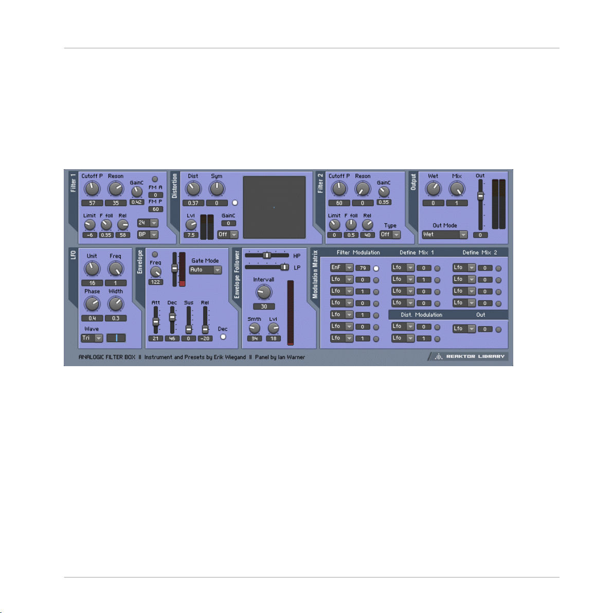
1.1 Analogic FIlter Box user interface
2.1.1 Introduction
The Analogic Filter Box sandwiches a rich and meaty distortion unit between two hearty analog-style filters to create a sound-shaping tool for every appetite. Juicy modulation is also provided on the side: An envelope, LFO, and envelope follower can be freely routed to the most
important filter and distortion parameters. Analogic Filter Box can handle everything from fat
disco-loop tweaking to full-on mangling of any sound source imaginable.
2.1.2 Structure and Signal Flow
The signal is routed from input to Filter 1, to the Distortion, to Filter 2, and then out.
REAKTOR Factory Library - Manual - 17
Page 18

Analogic Filter Box
Both filters offer multiple operation modes. For the first filter, you can choose between Lowpass, Highpass, Bandpass, Peak EQ, and Notch filters, with a choice of a 12 or 24 dB/octave
slope per filter type. The second filter is designed for shaping the sound after the distortion, so
it offers four different lowpass filters, three bandpass filters, and a bandpass/lowpass combo.
Both filters were very carefully designed to produce warm, analog sounds even at extreme resonance and cutoff settings.
Beside the normal cutoff frequency control available in both filters, Filter 1 also provides fast
modulation of its frequency by an additional oscillator (which can itself be modulated by the
LFO, envelope, or envelope follower!).
The Distortion section between the two multimode filters also features multiple modes of operation. While the clipper mode provides a relatively harsh distortion sound and the saturator
mode results in warm overdrive, the several wrapping modes (marked by the name of the waveform used for wrapping) produce unique sounds from subtle to extreme.
An additional quantize mode converts the incoming signal into a step waveform, for familiar
bit-reduction effects to mimic the character of vintage samplers, for instance. A visual display
of the distortion function helps to see what's going on inside.
2.1.3 Modulation
Analogic Filter offers six modulation sources (A built-in LFO, envelope follower, enveloper,
MIDI note pitch, modulation wheel, and pitch bend wheel). The modulation sources and the
flexible matrix signal routing system at the bottom of this effect transforms it into an incredibly
powerful machine.
Effects
The modulation signal routing system provides a source selector for each parameter to be
modified; among those modifiable parameters are the cutoff frequencies and resonance settings of both filters and the distortion amount and symmetry control of the distortion section.
In addition to gate information from MIDI note-on events that can even be used to trigger the
filter, you can also use the pitch and mod wheels as modulation sources.
An internal LFO, envelope follower, and auto-trigger envelope can add movement to the sound
without the need any external MIDI controllers. The LFO offers different waveforms and can also be synchronized to the global tempo or MIDI clock (the small Unit knob syncs the LFO to
MIDI clock and sets the musical note-units that are shown under Freq). The Envelope Follower
calculates its modulation amount from the incoming signal: At high levels there is a high modulation level, and at low levels it's low. The Interval knob controls the response time to fast
REAKTOR Factory Library - Manual - 18
Page 19
level changes. Use the cutoff controls of the internal highpass and lowpass filters to select a
specific frequency band of the incoming signal to trigger the envelope follower. The Envelope
is a standard attack-decay-sustainrelease envelope generator, triggered by MIDI note on events.
However, an additional auto-trigger feature allows it to be triggered by the incoming audio, settable with the Tresh slider.
It's even possible to combine any two MIDI controllers to make one dependent on the other for instance, to have the amount of LFO modulation dependent on MIDI pitch. You can define
custom mix modulation combinations in the Define Mix 1 and 2 areas as the bottom of the
instrument.
* You can play a sound through the built-in loop-player, through the realtime audio inputs, or
you can process audio in realtime by using Reaktor as an effect plugin. Please check your Reaktor or Reaktor Session user's guide for helpful information.
2.2 Anima
Effects
Anima
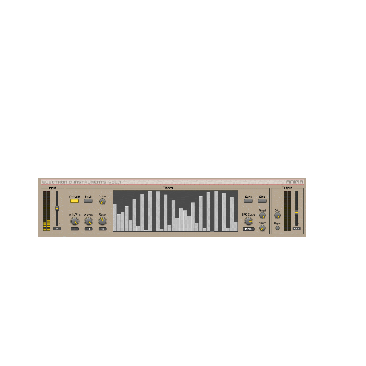
2.1 Anima user interface
Introduction
Anima is a polyphony-dependent filter bank, animated by an LFO that can produce complex
wave effects.
Input
<Level> Sets the input level, in dB. The meters show the post-fader input level.
REAKTOR Factory Library - Manual - 19
Page 20

Filters
A single bandpass filter corresponds to every voice of polyphony. All of the filters are controlled
together, in the main XY display.
• <Y->Wdth> If ON, the Y coordinate of the Xy controller in the center of this panel modulates the width of the frequency band that is covered by the bandpass filters. If off, the Y
coordinate modulates the phase offset or starting point of the wave that determines the
amplitude of the bands. The "missing" parameter can be set with the "Wdth/Phse" knob.
• <Keyb> If ON, incoming midi notes shift the cutoff frequencies of the bandpass filters.
Note that the actual cutoff frequency as set by MIDI notes is not displayed in the XY panel.
• <Wdth/Phse> Width / Phase control. If the "Y-Wdth" button is off this knob controls the
width of the frequency band that is covered by the bandpass filters in semitones. If the
"Y-Wdth" button is on it controls the phase offset or starting point of the wave that determines the amplitude of the bandpass filters. Values between 0 and 1 set the phase between 0 and 360 degrees.
• <Waves> Sets the number of cycles of the wave that determines the amplitude of the
bandpass filters.
Effects
Anima
• <Resonance> Sets the resonance of the bandpass filters in dB. The amplification is compensated internally so the resonance controls only the narrowness of the bandpass filters.
• <Drive> Sets the amplification before the distortion unit. The amplification is compensated internally so it controls the amount of distortion.
• <XY Panel> The XY panel shows a graphical representation of the amplitude and frequency of all bandpass filters.
◦ Display: X->frequency of the filters
◦ Display: Y->amplitude of the filters
◦ Controller: X->center of the frequency range that is covered by the bandpass filters.
◦ Controller: Y->either the width of the frequency range or the phase offset of the wave
that determines the amplitude of the bandpass filters (depends on the "Y->width" button on the left).
REAKTOR Factory Library - Manual - 20
Page 21

LFO
• <Sync> If ON, the LFO is synced to the global clock. Its length is then set in 16th notes.
The global clock can be started and stopped by the corresponding buttons in Reaktor’s
toolbox. If Reaktor is used as a plug in the clock of the host is used.
• <LFO Cycle> Sets the cycle length of the low frequency oscillator (LFO). The LFO modulates the phase offset of the wave that determines the amplitude of the bandpass filters.
If the "Snyc" button is on the length are set in 16th notes. If off the length is set in milliseconds.
• <Sine> Toggles the waveform of the LFO from triangle to sine wave.
• <Ampl> Sets the amplitude of the LFO.
• <Asym> Sets the amount of asymmetry of the LFO. E.g. a triangle waveform turns in a
sawtooth with a rising slope if the knob is turned fully clockwise. Counter clockwise it
turns into a sawtooth with a falling slope. In the center it remains a triangle waveform.
Output
• <Level> Sets the output level, in dB. The meters show the post-fader output level.
Effects
Anima
• <D/W>Dry / Wet control. It crossfades between the incoming signal (fully left) and the
processed signal (fully right).
• <Byps> Bypass switch which turns the effect off. When off, the CPU is no longer used.
REAKTOR Factory Library - Manual - 21
Page 22

2.3 Banaan Electrique
Effects
Banaan Electrique
1.2 Banaan Electrique user interface
2.3.1 Introduction
Banaan Electrique is a sophisticated guitar and bass amp simulator with built in effects. It's
like having a pedal board full of vintage pedals and a vintage amp, with the added advantages
of not needing to cable anything together or risk electrocuting yourself by running too much
REAKTOR Factory Library - Manual - 22
Page 23

Banaan Electrique
current through the amp. You can still get shocked by its lush sound, however. Naturally, Banaan is happy to eat whatever types of sounds you feed it, whether they're vocals, drum loops,
synths, or scallops.
2.3.2 Getting Started
Banaan Electrique was designed to be so easy that even guitar players can use it! Just play
some audio through it and let a rip.* Check out the presets to see the variety of tones that Banaan can achieve.
2.3.3 Structure and Signal Flow
The audio runs through Banaan Electrique linearly:
Input > mono gate > 3-band EQ > Compressor 1 > Amp Simulator > Phaser > Rotor > Dual
Delay > Reverb > Compressor 2
The incoming signal is converted to mono, amplified, gated, equalized and compressed to control the input's amplitude level and to enhance those sounds wanted to be in the recording,
getting rid of any unwanted noise. Then, a guitar amplifier is simulated, including distortion,
overdrive and filtering. Its output signal is sent to a rotor module, placing the mono sound in
the stereo field dynamically. This signal is then routed to a phaser effect and, afterwards, to a
stereo echo unit whose delay times can be synced to master tempo or MIDI clock. A high-quality reverb enhances the spatial sound once more, feeding its output into the final compressor.
Effects
Not all modules have to be active at the same time - in fact, it's a good idea to turn off any
modules that you're not using to save CPU. You can turn modules on and off with their respective Power buttons.
* You can play a sound through the built-in loop-player, through the realtime audio inputs, or
you can process audio in realtime by using Reaktor as an effect plugin. Please check your Reaktor or Reaktor Session user's guide for helpful information.
REAKTOR Factory Library - Manual - 23
Page 24
Classic Vocoder
2.4 Classic Vocoder
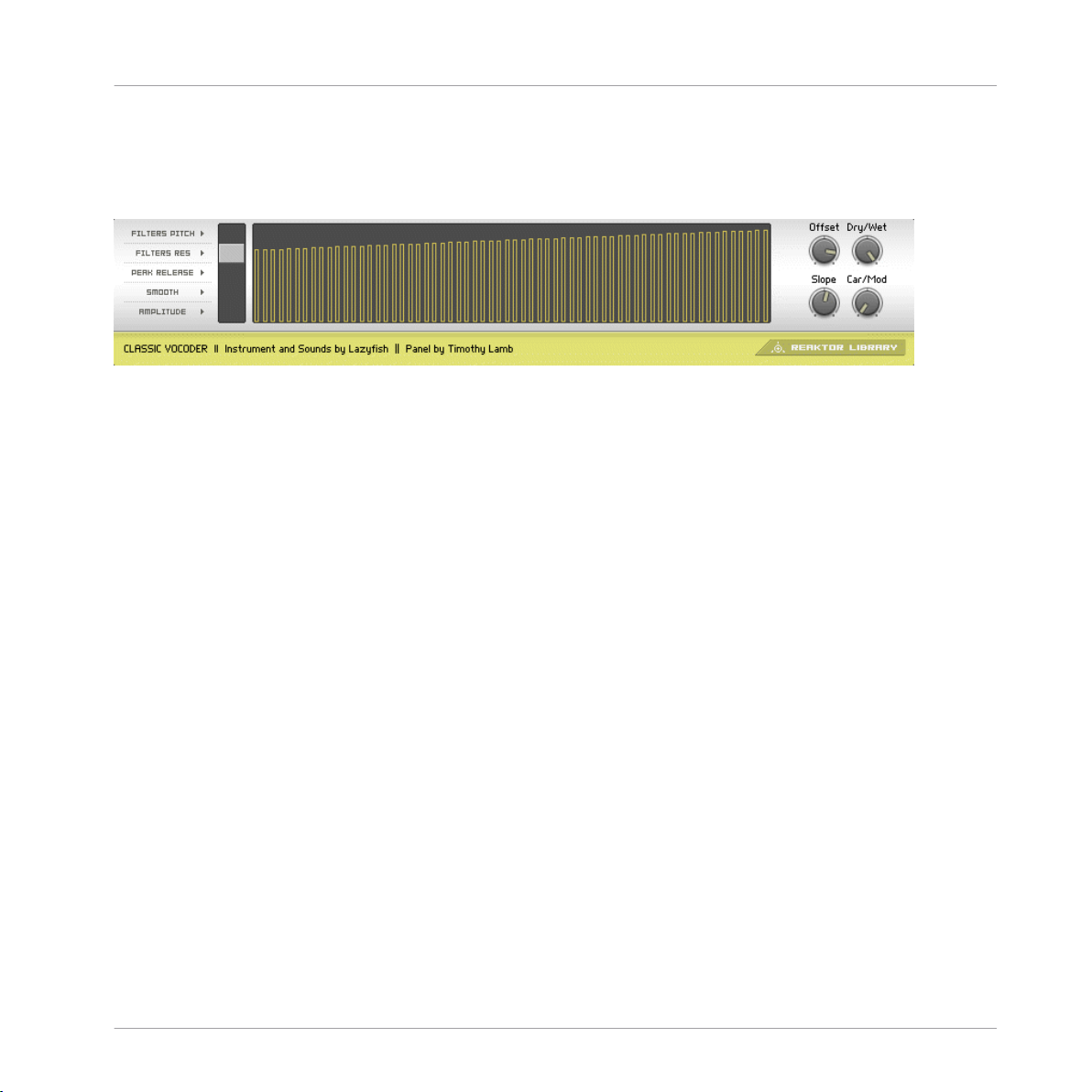
1.3 Classic Vocoder user interface
2.4.1 Introduction
The Classic Vocoder was designed to faithfully emulate the well-known tones of singing robots
made popular in the seventies. The instrument combines a vocoding engine, a vintage-type
synthesizer, and a four-band dynamics processor for a warm, smooth sound.
Effects
2.4.2 Quick Start
The audio input is vocoded with the built-in synthesizer. Play some audio into the vocoder.*
You don't have to sing into it - the Classic Vocoder also gives great results with drum loops or
other sounds.
2.4.3 Structure and Signal Flow
Audio input 1 is the modulator, and is vocoded with the Classic 2-VCO synth, which is the carrier. The entire signal flow is mono. If you are using a stereo signal, only the left channel will
be used. The output of the vocoder is fed into the four-band normalizer to smooth-out the
sound and remove any uncomfortable signal peaks that could come with vocal sibilants or
drum transients.
REAKTOR Factory Library - Manual - 24
Page 25
Classic Vocoder
2.4.4 The Vocoding Engine
Sonically, Vocoding uses the characteristics of one sound to control another. To achieve the
popular robotic-singing effect, a voice (technically called the modulator) is vocoded with a constant sound, such as a synth or string sound (the carrier). The frequency content of the voice is
split up into many different bands - the number of bands has an obvious impact on the sound,
with fewer bands leading to more synthetic voices, and higher bands make the voice easier to
understand. You can adjust the number of voices of the vocoder instrument to change how
many bands are used. Up to 128 voices (bands) are possible. All changes in number of bands
are immediately shown in the graphical display.
The amplitude of each frequency band of the voice is linked to the frequency bands in the
string or synth sound. The re-shaped bands of the carrier signal are mixed together, providing
the output signal of the vocoder.
If you're interested in vocoding, you may also want to do check out another NI product - the
VOKATOR. The VOKATOR features vocoding up to 1024 bands, a built in synthesizer and
granular sampler, and many high-end vocoding features. www.ni-vokator.com.
* You can play a sound through the built-in loop-player, through the realtime audio inputs, or
you can process audio in realtime by using Reaktor as an effect plugin. Please check your Reaktor or Reaktor Session user's guide for helpful information.
Effects
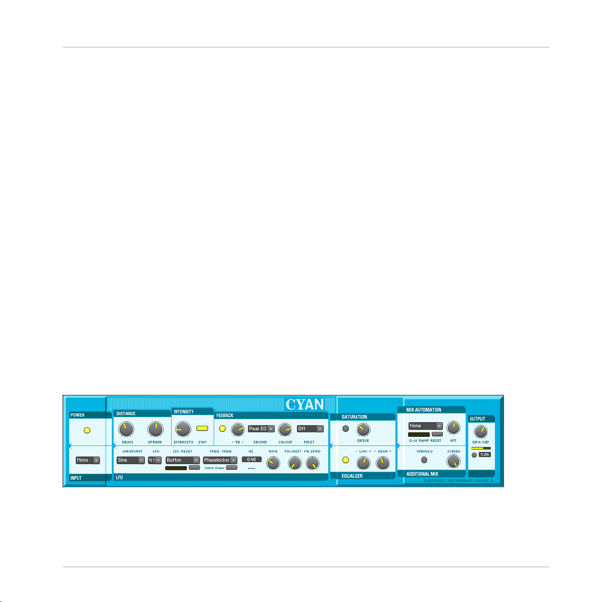
2.5 Cyan
3.2 Cyan user interface
REAKTOR Factory Library - Manual - 25
Page 26

Introduction
Like a traditional Chorus effect, Cyan uses a bank of modulated-delay units to add width,
depth and richness to the input signal. And due to painstaking attention to detail in the design
process, Cyan can reproduce classic chorus-type sounds with the finest sound quality. However, Cyan is far more than just a high-quality chorus unit. Indeed, due to its advanced features
such as tempo-synchronisation and extended delay modulation control, Cyan offers many new
and exciting sound-shaping possibilities.
Details
The effect's architecture consists of up to six independent stereo delay lines (see sections Distance, Intensity and LFO) that are fed with the incoming audio signal (see Input). Optionally,
the delay lines' output can be routed again to their input to establish an additional feedback
circuit (Feedback). After summing the delay lines' signal the sound is routed to a saturation
unit and an equalizer to dynamically and harmonically re-shape the chorused signal (Saturation and Equalizer). Finally, the signal is mixed with the unprocessed one and sent to the output (Mix Automation, Additional Mix and Output).
Section Function
Power and Input These two sections control whether the chorus is switched on or off and which signal
is used as input: The complete stereo signal, the left channel alone, or a mono mix of
both.
Effects
Cyan
Distance, Intensity,
and Feedback
The Delay knob on the other hand adjusts the delay times offset, thus controlling the
phase variation applied to the chorused signal in respect to the unprocessed signal.
The Spread control additionally changes this offset slightly for each LFO independently to enhance this effect. The Intensity knob mainly controls the sound of the chorus:
It determines the amount by which the delay times vary.
After passing through the delay units, the signal is routed to the Feedback section
where it can be filtered (using the Colour knob to control the filter's frequency), and is
then mixed with dry signal. The FB amount knob is bi-polar: At the right there is normal feedback, at the left the feedback signal's phase is inverted; at mid position the
feedback is turned off.
REAKTOR Factory Library - Manual - 26
Page 27

Section Function
LFO Waveform and LFO determine the shape and number of low frequency oscillators.
Rate controls how fast the delay times are modulated by the low frequency oscillators.
This speed is displayed either in Hertz or, if MIDI Sync is enabled, in rhythmical values.
MIDI Sync is only available if Freq. Mode is set to ‘Phaselocked’, meaning that the
phase of the LFOs is linked to each other. If it is set to ‘Freerun’, the LFOs' phase can
be spread (like the delay time offset) by the Ph.Spread knob.
Ph.Shift controls the phase to which the oscillators are reset at synchronization events
that can be specified with the LFO Reset switch; the button below this menu can be
used to manually synchronize the oscillators.
Effects
Cyan
Saturator and Equalizer
Mix automation and
output
After the chorus section itself the audio signal can be saturated and equalized.
Finally, the chorused signal is mixed with the unprocessed sound, defined by the Dry/
Wet balance knob position. Mix balance can also be automated by a ramp generator,
the speed of which is adjustable by the Speed knob. The ramp generator trigger source
can be selected at the left of the Att knob.
The small switch below the main Dry/Wet knob mutes the unprocessed audio, effectively converting the Dry/Wet knob into an amplifier for the processed signal. This is
especially useful when using Cyan as a send effect.
Tremolo enables amplitude modulation, synchronized to the delay time modulation.
The Stereo knob controls the spread of the audio within the stereo panorama.
REAKTOR Factory Library - Manual - 27
Page 28
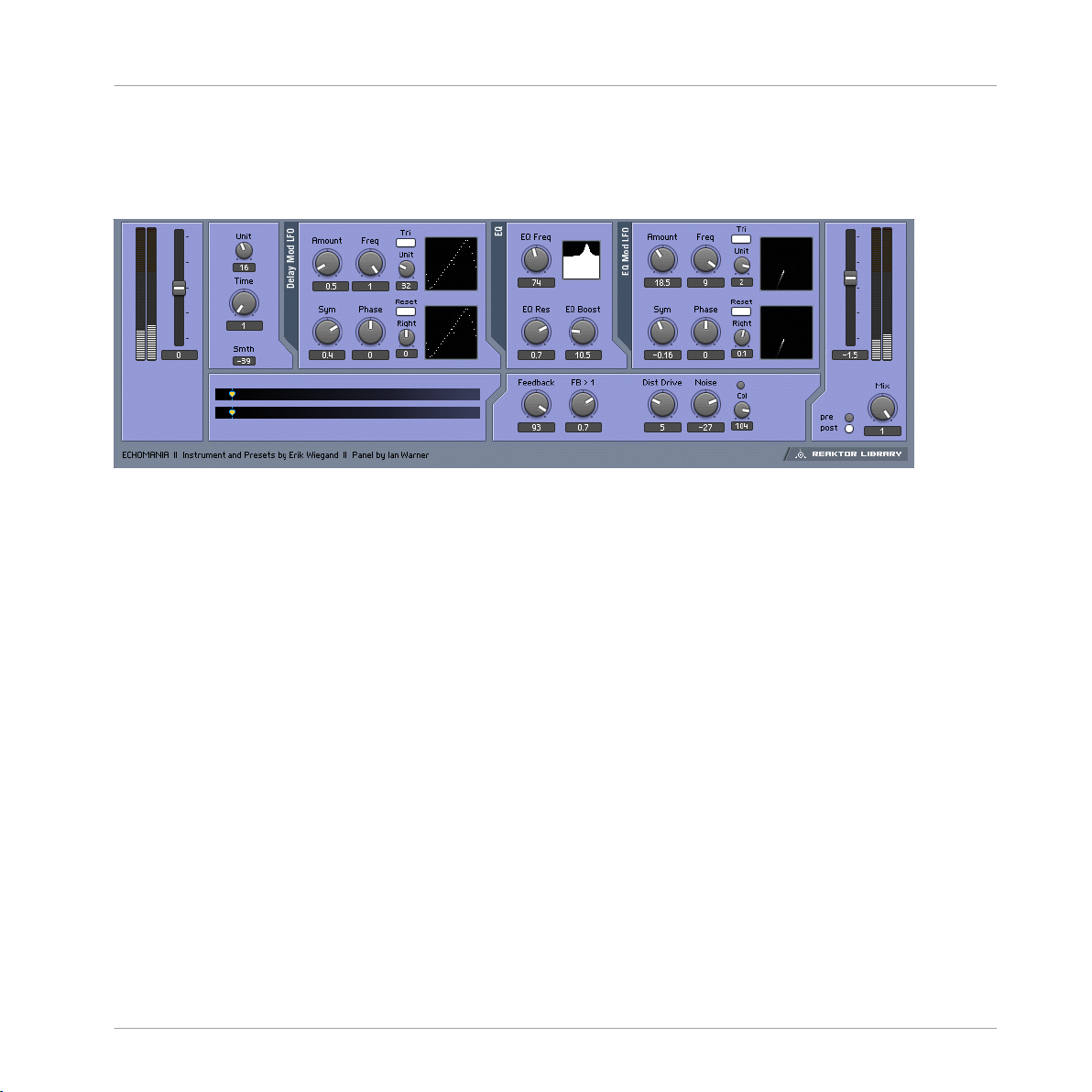
2.6 Echomania
1.4 Echomania user interface
2.6.1 Introduction
Echomania is an advanced and spectacular-sounding delay box that excels at tight, temposynced rhythms. It includes two LFOs to to modulate the delay time and built-in EQ. The delay
time is handily synced to the global MIDI clock, for creating stretchy rhythmic effects. A drive
and noise circuit combined with a feedback offset control recreate vintage sounds. Get dubbing!
Effects
Echomania
2.6.2 Quick Start
Play some audio through Echomania.* Flip through the snapshots and discover the gritty (or
crystalline) depths of Tapedelay.
2.6.3 Structure and Signal Flow
The delay time is set in 16th note increments, synced to the global MIDI clock. The Unit and
Divisor windows, to the right of the Time control, allow you to fine tune the beat division and
create different rhythmic feels—to be precise, the enumerator divided by the denominator
scales the delay time fraction.
REAKTOR Factory Library - Manual - 28
Page 29

There is also an LFO, with blendable sine/triangle/square/slow random waveshapes that is
hardwired to modify delay time. You can set the amount of time modulation with the Amount
knob. The Freq knob controls the rate of the LFO in 16th notes. The Unit knob divides the
speed of the global clock by the Unit amount. For example, if the Unit knob is set to "6", then
the LFO Freq amount will be in 16th notes. The Width control morphs between sine and pulselike, or, if the Tri button is engaged, triangle and saw tooth waveshapes. The starting phase of
the LFO can be adjusted positively or negatively using the Phse knob. If you engage the Snc
button, the right-side LFO can be phase-offset from the left side by the amount set with the
Right knob. This can create a variety of woozy stereo spinning and phasing effects.
The EQ module processes the delayed signal. It is essentially a parametric EQ that contains an
LFO identical to the one in the Delay module. You can create synchronized filter sweeps, fizzing hi-frequency delay tails, and all manner of dubby effects by boosting and modulating select frequency bands. The Eq Res control lets you dial in the peak width of the frequency,
while EQ Boost lets you crank it up.
Tapedelay's Feedback module provides an offset control, labeled FB > 1, which boosts and
shapes the feedbacl signal, making it seem to get louder and louder (but without degenerating
into uncontrollable noise).
The Mixer lets you add a tape saturation-like Dist Drive effect and Noise to give everything that
just-pulled-out-of-the-closet feeling.
Effects
Echomania
The Dry Wet section allows you to balance the amount of dry and delayed signal. You can also
use the Tap buttons to select whether the delay tap comes before or after the saturation/noise
circuit.
* You can play a sound through the built-in loop-player, through the realtime audio inputs, or
you can process audio in realtime by using Reaktor as an effect plugin. Please check your Reaktor or Reaktor Session user's guide for helpful information.
REAKTOR Factory Library - Manual - 29
Page 30
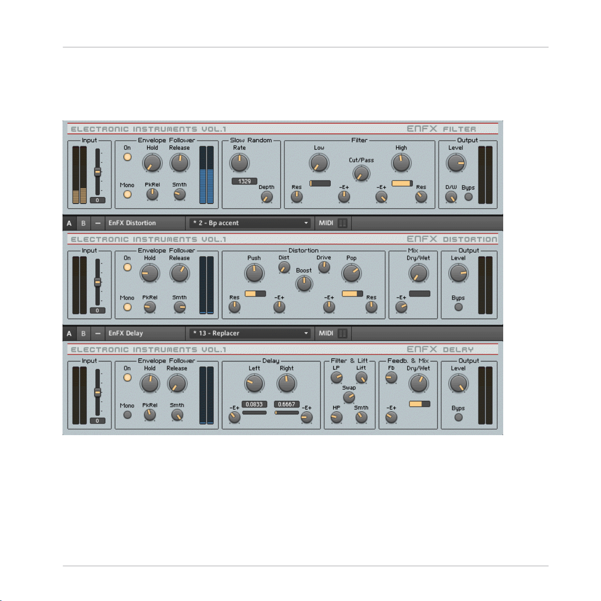
2.7 EnFX
Effects
EnFX
2.3 EnFX user interface
Introduction
EnFX consists of three separate effects: an envelope-follower filter, distortion, and delay. Even
though the effects are together in one ensemble, they can also be used independently. The ensemble is routed in series: Filter -> Distortion -> Delay. Each effect features a identical Input,
Envelope Follower, and Output sections. These sections will be explained first:
REAKTOR Factory Library - Manual - 30
Page 31

Input
<Level> Sets the input level, in dB. The meters show the post-fader input level.
Envelope Follower
An envelope follower isn t a dog that chases the postman. Instead, an envelope follower listens
to the incoming audio, and when the level of the audio exceeds a certain threshold, then a
simple HR (hold/release) envelope is triggered. This envelope can control different parameters,
depending on the effect. The result is an effect that wraps itself around the incoming audio for
an organic, natural sound.
• <On> Switches the envelope follower on or off to save cpu power.
• <Hold>, <Release> Set the hold and release values of a HR-envelope that is triggered by
a rising of the input level. It shapes the output of the peak detector. Lower values, i. e.
shorter hold and release times, result in a sharper response to level decays.
• <Mono> Switches between stereo mode (off) and mono mode (on). Use mono mode for a
more stable envelope. In stereo mode, the two incoming channels are processed seperately -a separate envelope of the left and the right channel is generated. In mono mode, both
channels are mixed together before extracting the envelope. ATTENTION: If a mono input
source is connected to both effect input channels, be careful using this switch: The envelope is already mono, so there’s no additional benefit; instead, by mixing, i. e. adding
both channels the signal is amplified and exceeds the normal range.
Effects
EnFX
• <PkRel> Sets the release time of the amplitude peak detector. Lower values at the left
result in more sensitivity to smaller peaks (e. g. HiHats), higher values instead only detect
really high peaks like bass drums etc.
• <Smth> Sets the amount of smoothing of the shaping envelope. Higher values result in a
more smoothed signal following the envelope of the incoming signal.
• <Envelope Meter L & R> Show the output of the envelope follower section.
2.7.1
EnFX Delay 1.3
At the center the EnFX delay is a delay whose time is modulated by an envelope follower. It s
useful for very long delays due to internal feedback enhancements as well as for unique pitch
shifting. See the envelope follower info above for information about the envelope follower section.
REAKTOR Factory Library - Manual - 31
Page 32

• <Left> Sets the delay time of the left audio channel. The display below shows the delay
time in 16th notes according to the midi tempo. Internally, the linear output of the knob
is processed by a function mapping it onto a grid to allow very short decays as well as very
long decays. The grid also performs triplet division of the time (0.3333, 0.1667, 0.0833
etc).
• <-E+> Sets the amount of modulation and its polarity applied to the delay time of the left
channel. Turn to the right for a longer delay times at high envelope follower signals, turn
to the left for shorter delay times at high envlope follower signals. Use mid position to
switch the modulation off.
• <Right> Sest the delay time of the right audio channel.
• <-E+> Sets the amount of modulation and its polarity applied to the delay time of the left
channel. Turn to the right for a longer delay times at high envelope follower signals, turn
to the left for shorter delay times at high envlope follower signals. Use mid position to
switch the modulation off.
• <LP> Sets the cutoff freqeuncy of a lowpass filtering performed to the feedback signal.
• <HP> Sets the cutoff freqeuncy of a highpass filtering performed to the feedback signal.
• <Lift> Sets the maximum level lifting. Turn right to amplify very silent signals in the feedback tail, turn left to amplify only the louder signals. Use it to make very long and damped feedbacks audible.
Effects
EnFX
• <Smth> Sets the amount of smoothing in the level lifting algotithm. Turn to the left for
smooth transistions, turn to the right for sharper and faster response to level changes.
• <Swap> Sets the amount and mode of channel swapping of the feedback signal. Turn to
the left for no swapping, i. e. the left channel remains the left one, the right channel the
right one. Turn to mid position for mono processing, i. e. both signals occur in both channels. Turn to the right for crossfading, i. e. the left channel signal becomes the right
channel signal and vice versa.
• <Fb> Sets the amount of feedback in the delay. More feedback leads to a decay with
more repeats.
• <Dry/Wet> Crossfades between the dry (unprocessed) signal at the left and the wet (processed) delayed audio at the right.
REAKTOR Factory Library - Manual - 32
Page 33

• <-E+> Sets the amount of modulation and its polarity applied to the dry/wet balance.
Turn to the right for a more wet signal at high envelope follower signals, turn to the left
for a more dry signal at high envlope follower signals. Use mid position to switch the modulation off. The yellow meter displays the actual value of the parameter modulated by —E
+.
Output
• <Level> Sets the output level, in dB. The meters show the post-fader output level.
• <D/W>Dry / Wet control. It crossfades between the incoming signal (fully left) and the
processed signal (fully right).
<Byps> Bypass switch which turns the effect off. When off, the CPU is no longer used.
2.7.2 EnFX Distortion 1.3
EnFX Distortion is a overdrive effect with a pre- and a post-distortion equalization filter whose
center freqeuncies are controlled by an envelope follower. Usefull for all kinds of overdive effects, but can also be used for guitar wahwah etc. due to the responce to level changes of the
incoming signal. In the distorion section, the left knobs belong to the "push" filter that modifies the signal before the distortion; the right knobs belong to the "pop" post-distortion equalizer. See the envelope follower info above for information about the envelope follower section.
Effects
EnFX
• <rEs L& R> Set the amount of resonance of the peak eq filters.
• <Push> Sets the freqeuncy of the pre-distortion peak equalizer
• <Res> Sets the resonance of the pre-distortion peak equalizer.
• <-E+> Sets the amount of modulation and its polarity applied to the frequency of the predistortion peak equalizer. Turn to the right for a higher frequency at high envelope follower signals, turn to the left for lower freqeuncies at high envlope follower signals. Use mid
position to switch the modulation off. The yellow meter displays the actual value of the
parameter modulated by —E+.
• <Dist>Sets the amount of distortion. On high distortion levels the signal might tend to
fade. Increase the drive value to fade it back in.
• <Boost> Sets the amount of amplification performed to the freqeuncies set by the Push
and Pop knobs.
REAKTOR Factory Library - Manual - 33
Page 34

• <Drive> Sets the amount of overdrive amplification.
• <Pop>Sets the freqeuncy of the post-distortion peak equalizer.
• <-E+> Sets the amount of modulation and its polarity applied to the frequency of the
post-distortion peak equalizer Turn to the right for a higher frequency at high envelope
follower signals, turn to the left for lower freqeuncies at high envlope follower signals. Use
mid position to switch the modulation off. The yellow meter displays the actual value of
the parameter modulated by —E+.
• <Res> Sets the resonance of the post-distortion peak equalizer.
• <Dry/Wet> Crossfades between the dry (unprocessed) signal at the left and the wet (processed) distorted audio at the right.
• <-E+> Sets the amount of modulation and its polarity applied to the dry/wet balance.
Turn to the right for a more wet signal at high envelope follower signals, turn to the left
for a more dry signal at high envlope follower signals. Use mid position to switch the modulation off. The yellow meter displays the actual value of the parameter modulated by —E
+.
2.7.3 EnFX Filter 1.3
An envelope follower filter is traditionally used to create ªwah wah sounds, but the flexiblity of
EnFX s design makes much more experimental sounds possible. See the envelope follower info
above for information about the envelope follower section.
Effects
EnFX
• <rate> Sets the rate of a slow random generator. The value displayed below shows the
time in milliseconds that goes by before another random event is generated.
• <Depth> Sets the depth of modulation, i. e. the amount by which the envelope follower
signal is modulated by the slow random generator. Turn right for more modulation.
• <Res> Set the amount of resonance, the left knob at the lower cutoff freqeuncy, the right
one at the higher freqeuncy. (See also <cut/pass>.)
• <Filter cutoff freq meter> Show the current cutoff freqeuncy. Here you can see also the
effect of modulation by the envelope follower and the slow random generator. Left represents a low freqeuncy, right a high freqeuncy. The meter on the left below the <LOW>
knob displays the frequency used in the lower filter, while the other one displays the freqeuncy of the higher filter. (See also <cut/pass>.)
REAKTOR Factory Library - Manual - 34
Page 35

• <-E+> Set the amount of modulation of the filter cutoff freqeuncies by the envelope follower ) whose signal before was modulated by the slow random generator). Turn left to
make the filter freqeuncy be reduced on high incoming envelopes, turn right for the opposite, i. e. high envelope signals increase the cutoff freqeuncy. The left knob modifies the
lower cutoff freqeuncy, the right one the higher freqeuncy. (See also <Cut/Pass>.)
• <Low> Sets the lower cutoff freqeuncy. (See also <Cut/Pass>.)
• <High> Sets the higher cutoff freqeuncy. (See also <Cut/Pass>.)
• <Cut/Pass> Crossfades between cut mode (left position) and pass mode (right position).
In cut mode, all freqeuncies below the lower freqeuncy set by <Low> and above the higher freqeuncy set by <High> are cut off, resulting in a bandpass filter whose boundaries
are specified by the lower and higher freqeuncy. In pass mode, all freqeuncies below the
lower freqeuncy set by <Low> and above the higher freqeuncy set by <High> are passed
through, resulting in a noth filter whose boundaries are specified by the lower and higher
freqeuncy.
Effects
EnFX
REAKTOR Factory Library - Manual - 35
Page 36

2.8 Fast FX
Effects
Fast FX
3.3 FAST FX user interface
REAKTOR Factory Library - Manual - 36
Page 37

Introduction
Fast FX is a set of 6 different effects: Freeze, zZZzZ, Slicemanipulator, Gate, Delay and Filter.
These effects can be chained in a variety of ways offering a large range of sounddesign possibilities. However, Fast FX’s speciality is live performance. Not only are all controls designed to
be tweaked in real-time, but Fast FX features a special ‘live’ snapshot system – enabling any of
the 256 states to be instantly recalled via simple keyboard strokes. This ability to instantly
switch between sets is what really brings Fast FX to life.
Quick Start
The most important thing to note is that Fast FX does not use the standard REAKTOR snapshot
system. Instead it uses a special 256-slot system operated by the panel and computer / MIDI
keystrokes. The 256 snapshots are made up of 32 x 8 slot banks. Select bank by the using the
32-step Program Selector slider at the bottom of the panel, and select the slot by using the
QWERTUI Selector above.
When Flow is enabled, selecting a new bank or slot automatically loads the preset. Press Write
to save the current ensemble state to the selected bank/slot.
Fast FX is supplied with a Loop-player for a useful sound source in REAKTOR standalone
mode, but it can also process live input (e.g. when used as a plug-in in a host sequencer.) The
Loopplayer input is selected by default, but to enable the Live input press the In 1/2 button in
the Input section. Fast FX will now process the audio input from REAKTOR audio-in channels
1 and 2.
Effects
Fast FX
Global Controls
Section
Input Fast FX has two pairs of stereo inputs. The first pair of inputs are connected to the
Junction This section allows configuration of the signal flow order between the 6 effects. Eight
Function
Loopplayer instrument, whereas the second pair are connected to REAKTOR’s audioin ports. Enable the 1/2 button to select the second pair (i.e. for use with live audio
input, or when using Fast FX as a plug-in inside a host application).
Level and Mute control the input level.
possibilities are available in the drop-down menu.
REAKTOR Factory Library - Manual - 37
Page 38

Section Function
Output Level and Mute control the output level. All effects can be bypassed simultaneously
with the Bypass button.
Mix The mix section controls the overall mix between the dry input signal and the wet,
post FX signal. The mix is defined separately for low and high frequencies with the
Low and High knobs. Link synchronises the two knobs.
Effects
Fast FX
REAKTOR Factory Library - Manual - 38
Page 39

The Effects
Section Function
Freeze The Freeze effect makes looping and scratching sounds.
Loop sets the loop length in musical time, from 1/16th to 4/1 (1 bar = 16/16th’s).
Spin determines how the loop length changes when the effect is enabled. A setting of
1/32 will result in a loop length that is 32 times shorter, a setting of 32/1 will result
in a loop length 32 times longer.
Spin Time determines the speed of loop length changing, and Jtr sets the delay time
jitter – the amount of slow, random variation.
Effects
Fast FX
zZzzZZ
This effect slices incoming sound into grains, and then slides the pitch, so that the
pitch of each successive grain is either decreasing or falling compared to the previous.
Slice A and Slice B set the length of first and second slices respectively, in 16th steps.
Length sets the grain length in milliseconds. Below, the knob labelled Mod sets the
amount of grain length modulation. Slide+ controls pitch slide, and the Mod knob below determines the amount of pitch modulation.
For both Length and Pitch modulation, a collection of pseudorandom, MIDI clock
synchronised patterns are used as the modulation source. The Rnd XY field is used to
select the current pseudo-random pattern (each pixel represents one of the 1920
available patterns).
Asym sets the grain size asymmetry between the left and right channels. Decay controls the dry signal decay time, the envelope is retriggered with each new slice (i.e. at
intervals according to the Slice A and Slice B controls).
REAKTOR Factory Library - Manual - 39
Page 40

Section Function
Slice Manipulator This effect also slices the incoming sound, and then shifts the position and playback
direction of the slices.
Slice A and Slice B set the length of first and second slices respectively, in 16th steps.
The two slicers work on a rotating basis, so therefore the slice lengths alternate between the two settings.
The SncVar enables a mathematical formula to automatically rearrange and vary the
slices in time. Set to zero for no variation.
Rev A and Rev B enable reverse playback of the first and second slices.
Effects
Fast FX
Gate
This section features a 16-step sequencer that modulates the amplitude of the incoming signal. The horizontal slider above the sequencer display selects one of the 20
available patterns for the sequencer, and the lower horizontal slider sets the sequencer clock speed. The preset sequence can be varied by reducing the loop length with
the Length knob, or by varying the playback position with the PosVar knob. This control
applies one of 16 variation patterns to the sequence playback order.
Gate determines the length of the open gate, as a proportion of a sequencer step. Release sets the time the gate takes to close.
REAKTOR Factory Library - Manual - 40
Page 41

Section Function
Delay The section features a stereo delay line with a modulated filter in the feedback path.
Delay sets the delay time in 16th steps, Fbck sets the feedback amount and Asym sets
the delay time asymmetry between the left and right channels.
Filter sets the centre frequency of the feedback filter. The cutoff is also modulated a
beat-synced LFO, controlled by the central XY field and Speed knob. The XY X axis
sets the LFO phase; the Y axis sets the modulation depth; and the Speed knob sets
the speed (cycles per bar).
Smth controls the speed that delay time changes (from the Delay / Asym knobs) are
applied, and also the crossfade speed of enabling/disabling the effect.
Effects
Fast FX
Filter
This section features a sequenced filter. The horizontal slider above the sequencer
display selects one of the 20 available patterns for the sequencer, and the lower horizontal slider sets the sequencer clock speed. Length sets the loop length of the sequencer. Mod defines how much the extent to which the sequencer modulates the filter cutoff.
Center and Reso set the filter cutoff and resonance respectively, and Width sets the filter width. Smth controls the speed that of changes to the cutoff frequency (from the
sequencer or the Center knob).
REAKTOR Factory Library - Manual - 41
Page 42

Snapshot control
Section Function
Q W E R TYU I In Fast FX, the REAKTOR snapshot menu is not used for handling snapshots. Instead,
with live performance in mind, the snapshot handling is dealt with on the panel.
Fast FX has a total of 256 snapshot slots, represented by 32 x 8 slot programs. The
32 programs are selectable by the Program Selector at the bottom of the panel. Either
click on the selector itself, use the Prev and Next buttons, or press computer keys ‘L’
or ‘;’.
Within each program, the 8 sub-slots are selectable by the QWERTUI Selector. To select a slot, click on the selector, or press the associated computer keyboard key (i.e.
Q,W,E,R,T,Y,U,I) or MIDI note (60,62,64,65,67,69,71,72).
The total 256 slot data is stored in a large event table inside the structure. If you wish
to export snapshot files, simply save the table data by right clicking on the table display either beneath the QWERTYUI selector or the Program Selector.
Bookmark
Flow and Write When Flow is enabled, selecting a snapshot position (via either the QWERTUI or Pro-
The bookmark feature enables you to store your favourite presets numbers and quickly
access them by using the dropdown menu.
To set a bookmark to the current state, take a look at the POSITION display, then open
the Bookmark list properties, and create an entry there with a name of your choice,
and the value displayed in the position meter.
gram selector) automatically recalls the data. Disable this if you want to copy the current state to another slot (i.e. disable Flow, select the desired Slot and then press
Write).
Write writes the ensemble state to the current bank and QWERTUI slot.
Effects
Fast FX
REAKTOR Factory Library - Manual - 42
Page 43

Loopplayer
Section Function
Panel controls This is an additional instrument for playing loops, it uses the REAKTOR Beatloop
module, and thus automatically stretches loops to the current tempo.
You can drop samples on the sampler window, or double click on it to open the REAKTOR map editor. Transpose should be set to 0 for all samples
Select the desired sample from the map using the Select knob. Loop Lng and Offset
and define the loop length, and position offset in 16th steps respectively. Pitch transposes the sample in semitones.
The Loopplayer has 16 different automatic variation patterns, these can be selected
with the Pos Variator knob.
Center and Reso set the filter cutoff and resonance respectively, and Width sets the filter width. The filter can be bypassed by pressing the Bps switch. Rnd Mrph determines
the amount to which a slow randomiser is applied to the filter cutoff.
Fit links sample pitch with time stretching, like a conventional sampler (i.e. the slower
the tempo, the lower the pitch).
Smooth controls the sampler grain smoothness, and Gain determines the output level.
Effects
Fast FX
Snapshot handling
The Loopplayer state is not saved in the Fast FX snapshot table, but pressing the Write
creates a snapshot in the Loopplayer instrument. Programs 1 to 16 are stored in bank
1 and programs 16 to 32 are stored in bank2. These are recalled when recalling snapshots on the Fast FX panel.
REAKTOR Factory Library - Manual - 43
Page 44

2.9 FlatBlaster 2
Effects
FlatBlaster 2
4.1 The Flat Blaster 2 user interface
2.9.1 Introduction
The great final-stage mastering tool FlatBlaster 2 has been rebuilt using the new REAKTOR
Core features. This patch combines four frequency-specific compressors with a full-spectrum
peak-limiter to produce a high-end package for your multiband dynamics shaping needs. As it
does not introduce any delay it is not limited to mastering use but can also be applied on a per
channel basis. The controls might appear intimidating at first glance, but are actually straightforward when you examine the signal chain. The separately compressed bands get mixed together and then processed by a full-band peak limiter. Please note that the master bypass for
the complete patch is situated to the left above the X Over section.
REAKTOR Factory Library - Manual - 44
Page 45

2.9.2 What’s New in 2.0.2?
Version 2.0.2 of Flatblaster 2 sports the following improvements:
• Lookaheads in compressors and limiter
• Smoother behaviour of envelope the followers
• Knee instead of saturation in the limiter
• Overall CPU consumption reduced
2.9.3 Multi-band Compressor
After the input stage the signal gets split into four independent frequency bands as defined by
the X Over section. Each frequency band gets processed by independent, identical compressors and can be independently muted, soloed and bypassed. Separate saturators for each band
make it possible, for example, to add punch and bite to the mids without affecting clarity in
the lower registers.
Section Control Function
Input Input Trims the input gain to prevent overload.
Effects
FlatBlaster 2
Bypass Bypasses the complete effect. This is the master bypass switching off all
compressors and the Limiter.
X-Over High Sets the crossover frequency between the High and Mid High compressor
bands.
Mid Sets the crossover frequency between the Mid High and Mid Low com-
pressor bands.
Low Sets the crossover frequency between the Mid Low and Low compressor
bands.
High, Mid High,
Mid Low and
Low Compressors
Stereo Sets stereo width of the frequency band. 0 is mono, 1 is original stereo,
2 is extra stereo.
Tresh Sets the point at which the compressor will begin to work (in db). Levels
below this threshold remain unprocessed.
Ratio Adjusts the ratio of the input level to the output level after compression.
REAKTOR Factory Library - Manual - 45
Page 46

Section Control Function
Knee This parameter adjusts how gradually the full amount of compression is
introduced. Think of it as a slope control for the attack time.
Sat Drives the band into saturation.
Link Activates stereo linking of the two input channels. When active, the com-
pressor takes the max of the left and right
peak levels and uses it for both channels. This preserves a clean stereo
image and is lighter on CPU cycles.
Att This dial adjusts the attack time. It is the time the compressor takes to
react to an above-threshold signal.
Rel With this control you set the release time. This is the time the compres-
sor takes to return the signal to normal when it falls below the compression threshold.
Out Gain Sets the amount of amplification applied to the compressed signal of the
specific band before it gets mixed with the other bands.
Bypass Bypasses the compressor for the respective band.
Mute Turns the sound of the respective band off.
Effects
FlatBlaster 2
Solo Turns all other bands off, leaving only the signal of the soloed band. Use
it to fine tune single compressor bands.
2.9.4 Full-band Peak Limiter
The peak limiter affects the full band signal. For clean mastering purposes we recommend a
limiter threshold setting of about -3 to -4 db and a peak setting at 0db. Should pumping effects be desired, adjust the threshold to more extreme values.
Control Function
Thr Adjusts the threshold of the limiter. Levels above this value get processed.
Peak Adjusts the hard limit of the signal. No signal will exceed this limit.
Rel This adjusts the release time. It is the time the limiter takes to return the signal to
normal when it falls below the limiting threshold.
Soft / Hard Balances between soft saturation and hard clipping of the above peak signal.
REAKTOR Factory Library - Manual - 46
Page 47

Control Function
Compare Controls the amplification of the uncompressed signal if Bypass is active. If you want
compression without amplification set it to 0 and make sure there is no change in level when toggling the Bypass button.
Link Activates stereo linking of the two input channels.
Bypass Bypasses the Full Band Peak Limiter only, leaving the 4 compressors active.
2.10 Flatblaster
Effects
Flatblaster
1.5 Flatblaster user interface
2.10.1 Introduction
Flatblaster is a high-end finalizing and multiband dynamic shaping tool. Flatblaster combines
four frequency-specific compressors with a full-spectrum peak-limiter. It is an excellent finalstep mastering plug-in, but it can also be used while mixing since it doesn't introduce any de-
REAKTOR Factory Library - Manual - 47
Page 48

lay to the signal. Each of the compressors has a saturator, so you could saturate just the uppermid frequencies, for instance, without muddying the bass. It also makes an excellent de-esser
and sibilant reducer.
2.10.2 Quick Start
Even though Flatblaster gives control over many sound-shaping parameters, there's no need to
be intimidated by its complexity. A full range of presets shows off its capabilities and gives
good starting points for tweaking the effect for your sound. Simply play some audio through
Flatblaster* and step throught the presets. Try experimenting with muting, soloing, and bypassing each individual band so you can carefully hear what the 'blaster's doing. Be careful
when adjusting the saturation of each band! The sound can potentially get very loud if you
don't first reduce the make-up gain (the knob labeled Gain to the right of the Sat knob).
2.10.3 Structure and Signal Flow
The input signal is divided into four bands - the three crossover frequencies are adjustable independently. Each frequency band is processed by an independent, identical compressor.
Each band can be muted, soloed, and bypassed (no compression). The signal is summed before going through a full-band peak limiter, which can also be independently bypassed. The
master bypass for the effect is located to the right of the input meters, above the crossover settings.
Effects
Flatblaster
2.10.4 Frequency-Specific Compressor
Each of the four compressors are absolutely identical. In fact, they have to be! If they weren't,
then unwanted phase shifts could creep in. Each compressor gives control over saturation, saturation makeup gain, threshold, compression ratio, adjustable knee, attack, release, and output makeup gain. Note that the Ratio has to be higher than 0 for the compressor to have any
effect - at a Ration of 1 (maximum), the compressor acts as a limiter. The red meters show the
amount of peak reduction. The Attack and Release knobs control how the compressor responds
to transient signals.
REAKTOR Factory Library - Manual - 48
Page 49

2.10.5 Full-Band Peak Limiter
The peak limiter affects the full frequency range of the audio, after each of the four frequency
bands has been compressed separately. The Threshold slider controls when the peak limiter
will start working. With Threshold at 0, the peak limiter will have no effect. For mastering, it's
recommended to have the Threshold set to around -3 or -4 dB. Severe Threshold settings will
lead to pumping, which may or may not be desirable. The Attack and Release knobs control
how the peak limiter responds to transient signals. The final Peak slider sets the output level of
the signal. When Peak is set to its maximum 0 dB, then the audio will be as loud as possible.
There's really no reason to ever set Peak lower than this, unless you needed to ensure a certain
amount of headroom.
* You can play a sound through the built-in loop-player, through the realtime audio inputs, or
you can process audio in realtime by using Reaktor as an effect plugin. Please check your Reaktor or Reaktor Session user's guide for helpful information.
Effects
Flatblaster
REAKTOR Factory Library - Manual - 49
Page 50

2.11 Fusion Reflections
Effects
Fusion Reflections
1.6 Fusion Reflections user interface
2.11.1 Introduction
Fusion Reflections is a delay-based effect that can create early reflections, shimmering choruses, fluttering delays, and even ambient reverbs. Two distinct diffusion engines are chained together to create an extremely wide range of effects. Each finely-tuned diffusion engine consists
of four stereo modulation delays and an innovative graphical display that shows the actual delay time for each delay. Just five controls control the core parameters of each diffusion engine.
REAKTOR Factory Library - Manual - 50
Page 51

Fusion Reflections
2.11.2 Quick Start
Play some audio through the effect* and select Preset 1 Long Decay Echo. This preset only
uses the Chor Fusion diffusion engine. Play with the Diff Dly knob - note how the graphic display constantly updates to show you the current delay times. Stop the incoming audio to listen
to the sound's decay. Play with Dly Mod and Speed to see what effect they have on the sound
and the graphic. Be sure to check out all the other presets to see how versatile this effect can
be!
2.11.3 Structure and Signal Flow
The sound passes through two diffusion engines serially. It's important to note that the two engines are similar but not identical - they each offer unique sound-shaping capabilities. The
first diffuser, Chor Fusion, is the simpler of the two and is designed for early reflections, choruses, and atmosphere. If offers a high and low shelf EQ, with a graphical display of the EQ
curve. The second diffusion engine, Echo Fusion, adds a feedback delay before the diffusion
delays. The diffusion delays in the Chor and Echo engines are identical. Echo Fusion is perfectly tailored to late reflections, long delays, and long reverbs. A highpass filter (HP) cuts the
low frequencies after the delay and before the diffusors, while a lowpass filter (LP) can reduce
the brightness at the last step. The input to the Echo Fusion engine can be switched between
the dry signal, and the signal coming out of Chor Fusion.
Effects
In the Mixer section the signals of Chor Fusion> and Echo Fusion are combined and mixed
with the dry signal. Each section can also be switched on or off to save CPU.
2.11.4 Diffusion Delays
Both the Chor and Echo Fusion engines contain identical diffusion delays. As mentioned
above, Echo fusion adds a single feeback delay before the diffusion delays, but the operation
of the diffusion delay section is identical per effect. Each diffusion delay consists of four stereo modulation delays and an innovative graphical display that shows the actual delay time of
each delay. The main delay time is controlled by the Diff Dly knob. The Dly Mod knob controls
the amount of delay time modulation by the internal LFOs. Speed controls the speed of the
LFO. Stereo sets the stereo spread of the delays, and Diffusion sets the inaccuracy of the delay
times. The sum effect of these five knobs is graphically shown in the display underneath,
where each "pendulum" represents the delay time of a single delay.
REAKTOR Factory Library - Manual - 51
Page 52

* You can play a sound through the built-in loop-player, through the realtime audio inputs, or
you can process audio in realtime by using Reaktor as an effect plugin. Please check your Reaktor or Reaktor Session user's guide for helpful information.
2.12 Grainstates FX
Effects
Grainstates FX
1.7 Grainstates FX user interface
2.12.1 Introduction
Grainstates is a granular texture maker that works wonders for creating dense, breathing atmospheres. Taking advantage of Reaktor 4's grain cloud delay module, GrainStates lets you
create granular soundscapes in realtime. You can even freeze the live audio - imagine playing a
guitar into Grainstates, freezing the audio, then playing a counterpoint to the granular texture.
Eight scenes - each scene storing information about grain size, density, pitch, pitch spread,
and more - are sequentially recalled in sync with the master tempo. A dual-frequency delay
adds depth to the sound by letting you specify independent delay and feedback times for the
high and low frequencies.
Grainstates consists of two ensembles: GrainStatesFX and GrainStatesSP. GrainStatesFX is an
effect using the grain cloud delay that works on live input, while GrainStatesSP is centered
around the grain cloud sampler module. The FX ensemble has the advantages that you can
REAKTOR Factory Library - Manual - 52
Page 53

easily process audio without loading anything into a sampler and you can freeze the incoming
audio stream - great for live performance! Since the sound passes through the ensemble, however, there's no way to save the sound data with the preset. GrainStatesSP stores the sample
with the preset so it can easily be recalled at a later time, but you must first load your sound
into the grain cloud sampler.
2.12.2 Quick Start
GrainStates FX: Start the system clock and run some audio through the ensemble.* You'll notice
a graphical representation of the sound "marching through" the granular buffer. To freeze the
buffer, press the Freeze button to the left of this graphical display. If you stop the system
clock, the sound will continue, but the scenes won't advance.
GrainStatesSP: Start the system clock and step through the presets. If you stop the system
clock, the sound will continue, but the scenes won't advance.
2.12.3 Structure and Signal Flow
At the heart of GrainStates is the granular grain cloud module. GrainStatesFX is based on two
(for true stereo operation) grain cloud delay modules, while GrainStatesSP is based on a single
grain cloud sampler module. Both the grain cloud delay and grain cloud sampler have identical
controls, with the grain cloud delay adding the ability to freeze the sound. All of GrainState's
controls (with the exception of the 2Band Delay) are used to control the grain cloud.
Effects
Grainstates FX
A master sequencer runs through eight scenes are run through sequentially, with each scene
providing control over various granular parameters. Every scene can have its own length, settable by the Ln slider, whose units are set in the Seq Control macro. You can also set the total
number of scenes (NrSt), and if you want to disable the scene sequencer simply click on "man"
and you can select a scene manually with the SelS knob.
Each scene provide control over pitch jitter (PJ: amount of pitch randomization, in semitones),
pitch shift (PS: in semitones), transposition (TP: in semitones), volume (Lvl), and an XY panel
lets you set two parameters graphically at once: The horizontal axis sets the start position of
the grain (relative to the graphical display on top of the internal buffer), while the vertical axis
sets the length of the grain. Three additional knobs provide control over the smoothness of
scene transitions, and the grain density smear (Smr).
REAKTOR Factory Library - Manual - 53
Page 54

GrainStatesFX only: The sound is filtered by the Filtor macro with independently adjustably
highpass (HP) and lowpass (LP) frequencies. Res adjusts the resonance of both filters, while
Byps disables the filter.
The output of the filters is fed back into the grain cloud delay, with feedback independently
adjustable per scene with the FB slider to the right of the XY control. The feedback is only active then the grain cloud delay is not frozen. When the grain cloud delay is frozen, it ignores
any signal to its inputs.
The sound then passes through a 2Band Delay, which gives independent control over delay
time in sixteenth notes (StepsL and StepsH), feedback (FBL and FBH), and a filter-modulating
LFO. The cutoff and resonance of the filter that splits the two bands is determined by the Frq
and Res knobs. Finally, a D/W knob sets the mix level. To bypass the filter, simply set D/W to
zero.
2.12.4 Additional Controls
Global Params. In the global parameters, you can set the global attack and decay of the grains,
and the amount of pan jitter (stereo randomization). In GrainStatesSP, this is also where you
select the active sample, with Sel.
Effects
Grainstates FX
GrainStatesFX only: the Move macro controls a built-in ramp oscillator that controls the delay
time. The Steady knob is the amount of delay modulation - when at zero, then the ramp oscillator does not change the delay time.
2.12.5 MIDI Control
In addition to automated sequencer control, GrainStates also lets perform with a MIDI keyboard. In the MIDI macro, you have control over the MIDI functionality. If "m TP" is activated,
then MIDI notes will pitch the sound, like in a conventional sampler. In GrainStates, however,
all notes are the same length, regardless of pitch. When "mSel" is active, each scene is mapped onto a note pitch between 48 and 59 (only the white keys of a keyboard); by pressing one
of the notes the respective scene is selected. With the Split knob you can specify another keyrange that recalls scenes. "m-tg" toggles MIDI triggering of sound on and off. GrainStatesFX
only: "m-frz" lets you toggle the freeze effect on/off via MIDI.
GrainStatesSP only: If you play GrainStatesSP over MIDI, you can activate the envelope (env
macro) to also control the amplitude of the sound with MIDI, according to the settings of the
envelope.
REAKTOR Factory Library - Manual - 54
Page 55
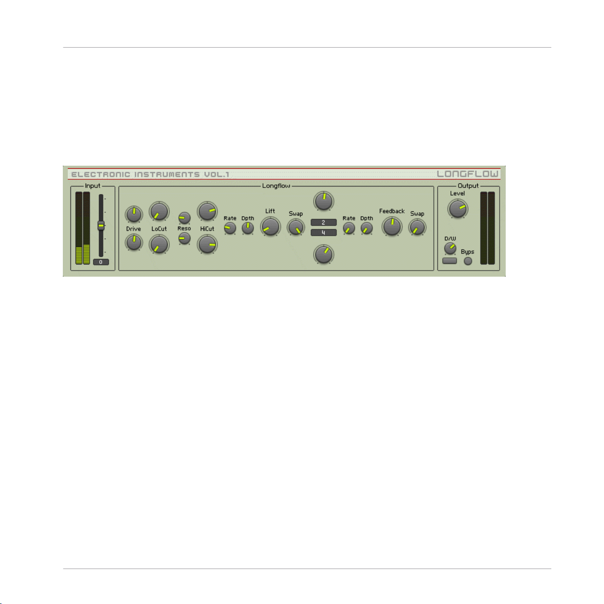
* You can play a sound through the built-in loop-player, through the realtime audio inputs, or
you can process audio in realtime by using Reaktor as an effect plugin. Please check your Reaktor or Reaktor Session user's guide for helpful information.
2.13 Longflow
2.5 Longflow user interface
Introduction
Effects
Longflow
Longflow is a delay effect with a finely-tuned feedback loop to create very slowly decaying echoes, or rhythmic grooves.
Input
<Level> Sets the input level, in dB. The meters show the post-fader input level.
Longflow
In Longflow, all controls that are vertically mirrored are separate controls for left and right. Left
is the top channel, and R is underneath. The following controls are mirrored — there is one
control each for the L and R channels:
• <Drive> Sets the amount of amplification performed to the left incoming signal. Use mid
position for no level change.
REAKTOR Factory Library - Manual - 55
Page 56

• <LoCut> Adjusts cutoff frequency of a 4-pole highpass filter. Together with the lowpass
filter that is controlled by the higher bounding frequency, they perform a bandpass filtering.
• <Reso> Sets amount of resonance for the filters.
• <HiCut> Adjusts cutoff frequency of a 4-pole lowpass filter. Together with the highpass
filter that is controlled by the lower bounding frequency, they perform a bandpass filtering.
• <Delay L, R> Sets the delay time. The display shows the delay time in 16th notes according to the MIDI tempo. Internally, the linear output of the knob is processed by a function
mapping it onto a grid to allow very short decays as well as very long decays. The grid also
performs triplet division of the time (0.3333, 0.1667, 0.0833 etc.).
The following controls effect both channels:
• <Rate> Sets the rate of a low freqeuncy oscillator whose output is modulating the higher
boundary freqeuncy of the filter. Turn right for higher rates, i. e. faster modulation.
• <Dpth> Sets the amplitude of a low freqeuncy oscillator whose output is modulating the
higher boundary freqeuncy of the filter. Turn right for higher amplitudes, i. e. more modulation of the freqeuncy.
Effects
Longflow
• <Lift> Sets the maximum level lifting. Turn right to enhance very quiet signals, esp. in a
long feedback tail with decaying audio. Be careful with this knob as also quiet noise and
clicks etc. are amplified and become very audible. Its effect increases if the drive knobs
are turn to the left.
• <Swap> Sets the amount and mode of channel swapping of the incoming signal. Turn to
the left for no swapping, i. e. the left channel remains the left one, the right channel the
right one. Turn to mid position for mono processing, i. e. both signals occur in both channels. Turn to the right for crossfading, i. e. the left channel signal becomes the right
channel signal and vice versa.
• <Rate> Sets the rate of a low freqeuncy oscillator whose output is modulating the delay
time. Turn right for higher rates, i. e. faster modulation.
• <Dpth> Sets the amplitude of a low freqeuncy oscillator whose output is modulating the
delay time. Turn right for higher amplitudes, i. e. more modulation of the delay time.
REAKTOR Factory Library - Manual - 56
Page 57

• <Feedback> Sets the feedback level, i. e. the loudness of the delayed signal that is mixed
with the incoming signal and delayed once more.
• <Swap> Sets the amount and mode of channel swapping of the output signal. Turn to the
left for no swapping, i. e. the left channel remains the left one, the right channel the right
one. Turn to mid position for mono processing, i. e. both signals occur in both channels.
Turn to the right for crossfading, i. e. the left channel signal becomes the right channel
signal and vice versa.
Output
• <Level> Sets the output level, in dB. The meters show the post-fader output level.
• <D/W> Dry / Wet control. It crossfades between the incoming signal (fully left) and the
processed signal (fully right).
<Byps> Bypass switch which turns the effect off. When off, the CPU is no longer used.
2.14 Resochord
Effects
Resochord
3.8 Resochord user interface
REAKTOR Factory Library - Manual - 57
Page 58

Introduction
Resochord imprints harmonic structures onto any input signal – including percussive sounds
with no existing harmonics. It essentially consists of 6 feedback units, which can be considered analogous to the strings of a guitar, which are effectively ‘plucked’ by the shape and
rhythm of the input signal. As each ‘string’ resonates at a different frequency, rich and luscious chords are generated – and thus remarkably, any input signal can be transformed into a
unique, MIDI playable instrument.
Quick Start
As an effect unit, Resochord requires an input signal. In REAKTOR standalone mode, the REAKTOR tape-player is an ideal source. To open the tape-player, click on the REAKTOR ‘View’
menu, and select, ‘Show Playerbox’, then load an audio file as desired.
There are various ways with which to control the pitch of the 6 resonators, as detailed later in
this manual. However, to play Resochord in real time from your MIDI keyboard, select Direct
Pitch (MIDI) from the MIDI & Logic control menu on the ensemble panel.
Signal-flow Overview
First the input signal passes through an optional high-pass filter and is then routed to the main
resonators. The output from the resonators is passed on to a high shelf equalizer (Refresh) and
a dynamic range controller (Norm) before it is mixed again with the dry, unprocessed input signal and sent to the output.
Effects
Resochord
REAKTOR Factory Library - Manual - 58
Page 59

Section Function
MIDI & Logic Control The main menu in this section selects from various modes of controlling the pitch of
the 6 resonators. Regardless of the control method, the pitch of the resonators is always displayed in the 6 values at the top of the Chord Structure menu.
When Direct Pitch (MIDI) is selected, the pitch of resonators is determined by MIDI
note input. This mode enables live play as with any keyboard instrument.
Direct Pitch (Manual) enables the 6 large pitch knobs at the bottom of the Chord
Structure section.
The Slot modes allow the user to store and recall the pitch of the resonators in 6
memory slots. This offers an alternative method of live performance (especially for
those with lesser keyboard skills!), allowing the user to recall from the 6 predefined
pitch configurations as and when desired.
When Slot (Midi) is enabled, the 6 memory slots are recalled by pressing MIDI notes
C36, D38, E40, F41, G43, and A45. Alternatively, in Slot (Manual) mode, the 6 slots
can be recalled by the 6 slot buttons on the panel.
To store a pitch configuration to a slot, select Record to Slot, then select the desired
destination slot by clicking on the appropriate slot button. In Manual mode, firstly
configure the desired 6 pitches using the knobs in the Chord Structure section, and
then press Store. In MIDI mode, firstly select the desired slot, and then simply press
the desired notes on your MIDI keyboard.
Effects
Resochord
Chord Structure
As mentioned above, the 6 values at the top of this section display the current pitches of the resonators. The 6 knobs at the bottom are used for defining the 6 pitches in
manual pitch modes.
The main window allows configuration of various parameters for the 6 resonators. Adjustable parameters are Lev (volume level), FB (resonator feedback amount), Cut (filter cutoff), Fine (fine pitch adjustment), LFO (amplitude modulation depth by the
LFO), and Pan (position in the left-right stereo field).
REAKTOR Factory Library - Manual - 59
Page 60

Section Function
To select which parameters to edit, click on the button next to the parameter label.
Then click and draw in the main window to edit the parameter for the 6 resonators.
InitSel or InitAll reset the values for the 6 resonators for either the selected parameter, or all parameters respectively.
Input Input defines the amplitude of the input signal (0 - 100%). The Clip lamp will light if
the input signal is too loud.
Highpass This section applies a 12db highpass filter to each of the 6 resonators. The cutoff
frequency is linked to the pitch of each resonator, Cutoff sets the offset between each
filter cutoff and the actual resonator pitch (-40 to +40 semitones).
Placement defines the filter's position within the signal flow. It can be placed before
the main comb filter section (Pre) or after it (Post), or disabled altogether (Off).
Resonator A resonator is essentially a feedback loop with a short delay time, the length of which
determines the resonator pitch. While the specific configuration of the 6 resonators is
defined in the Chord Structure section, the Resonator section allows configuration of
2 global parameters – the Feedback Filter mode (lowpass or notch) and the method of
Feedback Control, required to prevent overflow from the feedback. Sat and Clip offer
soft-curve, or hard-clipping of feedback above 0db, and both work on individual samples, whereas Limit operates more akin to an analog compressor, reducing the volume
of the feedback when the signal exceeds 0db.
Effects
Resochord
Diffuse Feedback The Diffuse Feedback unit applies an allpass filter to the feedback chain that adjusts
the signal's phase for interference effects.
Color sets the center frequency (26..8400 Hz) of the feedback's allpass filter. As the
filtered signal is added to the unfiltered one, some special interference effects become audible.
Amount sets the amount of diffuse feedback. This is a bipolar control – when centered there is no feedback, at the right there is normal feedback, and at the left the
feedback signal is inverted for special interference with the allpass filter.
REAKTOR Factory Library - Manual - 60
Page 61

Section Function
Harmonics This section adds additional harmonics to output of each resonator. In essence it is
an additional resonator stage (without feedback) for the output of each main resonators.
The Ratio knob adjusts the ratio between the original pitch and the additional harmonic pitch. It ranges from infinitely higher (at hard-left) to 1 octave higher (i.e.
twice as high) (at hard-right) than the main resonator pitch.
Refresh Sets the amount of amplification (0db to 10db) applied to frequencies above 1 kHz.
Use this knob to ‘refresh’ dull sounding signals.
Norm Enabling this section maximizes the volume of the output signal.
Output W. Srce (Wet Source) determines whether the output signal is taken from the begin-
ning of the comb filter's feedback loop (Pre), or from the end (Post). If the former,
the dry, unprocessed signal is more prominent in the wet signal.
Amp sets the amplitude of the wet signal before it is mixed with the dry signal.
D / W (dry / wet) defines the balance between the dry, unprocessed signal (left) and
the wet signal (right).
Effects
Resochord
Global Pitch Coarse and Fine shift the overall pitch of the resonators in semitones. PB sets the
pitch bend range in semitones, and NP! enables global pitch shifting by MIDI note
keys C60 to C96.
REAKTOR Factory Library - Manual - 61
Page 62

Section Function
Envelope Follower The envelope follower tracks the amplitude of the input signal, and then uses the de-
rived signal to modulate resonator feedback, cutoff and colour.
Hold adjusts the length of the hold period of the envelope follower after an envelope
peak in the input signal (1 to 10000 msec), and Release adjusts the length of the
release period (1..10000 msec).
FB, Cut and Colour define the extent to which the envelope follower modulates resonator feedback, cutoff and diffuse feedback colour respectively.
Note that as that FB is unipolar, setting to hard-left results in no modulation, whereas Cut and Colour are bipolar, and thus setting to centre results in no modulation.
Effects
Resochord
LFO
Rate specifies the oscillation rate of the LFO (0Hz to 3.6 Hz). Width sets the symmetry of the LFO shape.
Delay specifies the amount to which the LFO modulates the resonators delay time
(i.e. amount of vibrato). Ratio sets the amount of influence of the LFO on the Harmonics' Ratio.
REAKTOR Factory Library - Manual - 62
Page 63

2.15 Space Master 2
Effects
Space Master 2
4.3 The Space Master 2 user interface
2.15.1 Introduction
The well-known Space Master series of reverb modellers has been updated for REAKTOR 5.
Based on several diffusion delays, Space Master 2 can produce a wide array of high-quality
natural or experimental ambiences. The patch’s efficient set of reverb parameters include an
early reflections section, a late reflections module and a post EQ. Dials for main reverb time,
control of balance between the two reflection stages, and between dry and wet signal round off
the controls.
REAKTOR Factory Library - Manual - 63
Page 64

Space Master 2
2.15.2 Input and Output Stage
You can introduce an initial delay into the reverb signal with the predelay [Time] dial and control the predelay’s stereo position with the [Symmetry} knob. The [Early / Late Balance] slider
can be used to move the source in space – more early reflections bring the signal to the front
and more late reflections make it appear further back in space. At the end of the signal chain,
the [Dry / Wet] slider crossfades between the dry original signal and the processed sound.
Section Control Function
Predelay Time Sets an initial delay for the wet signal.
Symmetry Introduces a difference into the delay times for the right and left predelay
channels. Use this to shift the signal around in the stereo image.
Effects
Mixing Early/Late
Balance
Dry / Wet This controls the balance between dry and wet signal.
With this parameter you can set how much of the early and late reflections, respectively, can be heard in the output.
2.15.3 Reflections
Use the two [Size] and [Diffusion] parameters to dial in the early and late stages of variable
density diffused reflections. The early stage commonly represents the direct response of the
virtual space, whereas the late reflections define the sound when the early reflections have
died away.
For dynamic reverb effects you can use the Modulation section. It offers an LFO routed to the
delay times with [Rate] and [Depth] control. The LFO can enhance your reverb signal by adding
liveliness.
Section Control Functions
Early/Late
Reflections
Size Determines the range of space generated by the early or late reflections mod-
ules by adjusting delay time of the underlying diffusion delays. Higher values
give the impression of larger spaces.
Symmetry Introduces a stereo shift into the generated reflections.
Diffusion Adjusts the perceived density of the generated reflections. Dial for a sparser or
fuller reverb sound.
REAKTOR Factory Library - Manual - 64
Page 65

Space Master 2
Section Control Functions
Reverberation
Time
Modulation Rate Control of LFO frequency modulating the delay times.
Depth This adjusts the LFO’s modulation depth. Higher values give you higher ampli-
This control alters the decay time of the reverb response.
tude of the modulation.
2.15.4 Frequency Response
The two EQ sections serve slightly different needs. The Damping EQs are integrated into the
reflection stages and influence their frequency responses. The Post EQ acts on the main output of the patch should be used to color the overall sound.
Section Control Function
Frequency
Damping
Low Frequency
Damp
Low shelving filter that cuts into diffusion delay frequency response of both early and late reflections. Use the horizontal slider to adjust cutoff frequency and the vertical slider to adjust cut
or boost.
Effects
High Frequency
Damp
Post EQ Low Frequency
Boost
High Frequency
Boost
High shelving filter that cuts into diffusion delay frequency response of both early and late reflections. Use the horizontal slider to adjust cutoff frequency and the vertical slider to adjust cut
or boost.
A low shelving EQ that acts on the main output of the reverb.
Use the horizontal slider to adjust cutoff frequency. The vertical
slider adjusts cut or boost.
A high shelving EQ that acts on the main output of the reverb.
Use the horizontal slider to adjust cutoff frequency. The vertical
slider adjusts cut or boost.
REAKTOR Factory Library - Manual - 65
Page 66

2.16 SpaceMaster
1.8 Space Master 1 user interface
2.16.1 Introduction
The SpaceMaster series of reverbs breaks new ground in reverb modelers for Reaktor. Spacemaster uses two different Diffusion modules to achieve stunningly convincing room sounds.
And to fully exploit SpaceMaster's lushness, there are three versions - SpaceMaster stereo,
SpaceMaster Quad, and SpaceMaster 5.1 Surround.
Effects
SpaceMaster
Quick Start
To really get a feel for the kinds of lush atmospherics SpaceMaster can provide, it's a good
idea to either hook a beat looper or external sound source up to it, or, to utilize it in plugin
mode in your favorite audio sequencer. Stepping through the presets should give you a good
impression of the kinds of real and imaginary spaces SpaceMaster can emulate. Adjusting the
controls of the Early and Late Diffusion modules will have the most effect on the sound, and
will give you an idea of how the two main components interact in creating ambiences - especially since they can be arranged in serial or parallel signal paths.
REAKTOR Factory Library - Manual - 66
Page 67

Structure and Signal Flow
This guide will use the Stereo SpaceMaster ensemble to outline the various controls for shaping the reverb signal, since most of them are the same among the three types of SpaceMasters.
Read on below to learn about the specifics of the Quad and Surround flavors of SpaceMaster
reverb.
Effects
SpaceMaster
REAKTOR Factory Library - Manual - 67
Page 68

2.16.2 SpaceMaster 5.1 Surround
Effects
SpaceMaster
1.9 Space Master 5.1 Surround
The Surround version of SpaceMaster is effectively the same as the Quad version (↑2.16.3,
SpaceMaster Quad), except that it adds a Center channel. The PreDelay XY pad adds control
for the center channel. SpaceMaster Surround also adds an Output Gain section that allows
you to use precise metering to control the relative volumes of the Center, Sub, Front, and Sur-
REAKTOR Factory Library - Manual - 68
Page 69

round reverb signals. The balance of Early/Late signal can also be adjusted for each channel
using the Mix module, which has familiar controls for wet/dry levels. Finally, SpaceMaster Surround does not include the EQ module found in the Stereo and Quad versions.
2.16.3 SpaceMaster Quad
1.10 Space Master Quad user interface
Effects
SpaceMaster
The SpaceMaster Quad ensemble works in the same way as the stereo version (↑2.16.4,
SpaceMaster Stereo), but it splits the reverb signal into four discrete outputs for using in a
four-speaker system. The signal for the forward speakers is referred to as the Front signal,
while the signal for the rear speakers is referred to as the Surround, or Sur, signal. In the Input
section, you can adjust the gain for Front and Sur signals to determine how much signal sources reaches each signal chain.
The PreDelay section is simplified from its stereo brother by use of an XY pad to finely adjust
Front and Surround L/R offset. The overall PreDelay time can be controlled by the Time fader.
The Early Diffusion section is also simplified, offering only Size and high frequency Cut controls for both Front and Surround diffusion signals.
The Late Diffusion module is effectively the same as the one found in SpaceMaster Stereo. Refer to the description above the learn how it works.
The Mix section allows you to balance the Front and Surround signal amount and to adjust the
wet/dry mix for each.
REAKTOR Factory Library - Manual - 69
Page 70

2.16.4 SpaceMaster Stereo
SpaceMaster Stereo is composed of a PreDelay module, an Early Diffusion module, a Late Diffusion module, and a post EQ. The Diffusion modules can be combined together to create a
complex impression of space. By adjusting the balance of the Early and Late diffusion modules, you can precisely move the origin of the reflections from near to far (or front to back),
making SpaceMaster perfect for Surround mixing situations in which a truly room-filling reverb
can be created.
The Input section, at the fat left, allows you to trim the input gain to avoid overloading the audio signal. The input is next processed by the PreDelay. Use this to add an initial delay to the
wet signal. You can also use the L/R offset knob to add some perceived stereo width by altering
the delay time of the left-side single delay module. You can bypass the PreDelay with the Byps
button.
Next in the signal path, the Early Diffusion module, which is actually a series of up to 12 diffusion delays, provides the near reverb processing. The Size control allows you to determine
the range of space that the close reflections will be generated by. It changes delay time in milliseconds. The Diffusion knob lets you adjust the density of the reverb signal. To further adjust
the reverb depth of the Early Diffusion module, the Mode switch allows you to select 6 or 12
diffusion modules. Watch your CPU load carefully to make sure your computer can handle the
strain of processing with 12 (or 24) diffusion modules. The Damp knob controls the frequency
of a 1-pole low pass filter for attenuating high frequencies. As in the PreDelay section, clicking
the Byps button will take the Early Diffusion module out of the signal path.
Effects
SpaceMaster
The Routing switch, located between the Early and Late Diffusion modules, lets you determine
how the input signal will be routed through the two modules. The Ser button engages Serial
mode, where the Early Diffusion module is simply routed directly into the Late module. The
Par switch engages Parallel mode, allowing the Early and Late modules to maintain separate
signal paths, until they are mixed at the EQ module. You can also use the Early/Late knob to
balance the amount of early and late reverb signal. This is a great way to change the perception of location within a space, by shifting between the early and late reverb sounds (to make it
seem like a sound is moving around inside of the "room").
The Late Diffusion module provides the capabilities for creating a larger and more richly defined space. The Size and Diffusion knobs work the same way as those in the Early section, but
there a few new options. The RT knob controls a feedback loop, allowing you to stretch out the
apparent reverb time, or the time it takes for the echo to return to the point of origin. There are
REAKTOR Factory Library - Manual - 70
Page 71

also controls for high and low shelving EQs, called Hi Damp and Lo Damp, respectively, that
allow you to shape the frequency range of the reverb signal. You can modulate the delay time
and apparent position of the reverb signal by using the modulation controls. The Spin knob adjusts the amplitude of a sine wave LFO, while the Dizzy knob controls amplitude for a Slow
Random LFO. You can create complex modulations by adjusting the balance of sine wave and
random LFOs. The Freq knob controls the rate of both LFOs together. As in the Early section, 6
or 12 diffusion modules can be selected with the Mode switch. This section can also be bypassed with the Byps button.
Both the Early and Late Diffusion sections feed into the EQ. The EQ consists of stereo low
shelf, parametric, and high shelf filters. Starting at the left, the Lo knob lets you control attenuation or boost of the low frequency set with the Frq immediately above. The Mid knob controls the parametric EQ band. The Frq and Q knobs above it let you adjust the frequency and
bandwidth of the parametric. The Hi knob controls attenuation of the high shelf filter. Use the
Frq immediately above the Hi knob to adjust the frequency. As in the other modules, the EQ
can be taken offline with the Byps button.
Finally, the mixture of wet and dry signal can be adjusted to taste with the Mix knob in the
output section.
Effects
Spring Tank
2.17 Spring Tank
1.11 Spring Tank user interface
REAKTOR Factory Library - Manual - 71
Page 72

2.17.1 Introduction
Spring Tank pays homage to the trashy, unrealistic spring reverbs of the past. While Spring
Tank isn't exactly a physical model of a spring, it goes a long way toward recreating the spring
reverb characteristics: dull, transducer-saturated, and boingy, with the familiar nonlinear resonating decay.
2.17.2 Quick Start
Spring Tank is meant to be an experimental effect, rather than a realistic one, play some audio
through the effect* and experiment! It allows control over the elements of the "spring's" morphology, so you can design your own spring.
2.17.3 Structure and Signal Flow
The input source is amplified or attenuated with the Level knob at the far left of the instrument. High levels here can introduce transducer saturation (which is not such a bad thing).
The signal is then fed into the spring tank. Here, you can adjust the spring's physical characteristics. The Damp knob sets high frequency damping for the spring. Turning the knob clockwise increases the damping. Stiffness, which mimics the flexibility of the spring, gives brighter, more resonant sounds at higher settings. The Shape knob allows you to crossfade between a
round spring shape to the left, and a rectangular one to the right. The round shape emphasized
a ringing sound, while the rectangular shape creates less ringing but a more diffuse sound.
Effects
Spring Tank
The Thickness of the spring determines the virtual diameter of spring winding, and therefore
the overall length of the spring. Longer spring settings result in reduced brightness. The
Length setting reflects global length. Turn this up to increase the shattering decay sounds. The
Decay knob changes the length of the decays. It alters the amount of feedback in the system.
Switching the Mono button off engages an additional short delay in one channel, resulting in
the simulation of stereo.
The Suspension section allows you to mimic the type of spring suspension in the system. When
you turn the knob to the left, you increase the "softness" of the suspension material. This will
lengthen the decay rate of lower frequencies. What this is actually doing is adjusting the cutoff
REAKTOR Factory Library - Manual - 72
Page 73

Two Knees Compressor
of a high pass filter in the feedback loop. Suspension will therefore also have an effect on the
sound of the Transducer saturation. The Color knob lets you adjust a global tone control. Turning this clockwise results in a brighter sound, and vice versa.
The Level knob controls the volume of the wet signal. You can adjust the balance of wet signal
to dry signal with the Mix knob. Finally, you can bypass the effect all together by clicking the
On button.
* You can play a sound through the built-in loop-player, through the realtime audio inputs, or
you can process audio in realtime by using Reaktor as an effect plugin. Please check your Reaktor or Reaktor Session user's guide for helpful information.
2.18 Two Knees Compressor
Effects
1.12 Two Knees Compressor user interface
2.18.1 Introduction
Two Knees Compressor is a simple compressor with an important quirk it has two separate adjustable thresholds and ratio controls. 2-Knees Compressor can perform as a precisely accurate
compressor/limiter, a distorting sound shaper, a transient modifier, or anything in between. It
includes a compression curve display to show the relationship between the amplitude of the
input signal and the amplitude of the processed signal.
REAKTOR Factory Library - Manual - 73
Page 74

Two Knees Compressor
2.18.2 Quick Start
Play some audio through Two Knees*. Try to input a beat and run through the snapshots to
hear a clear example of how it can alter transients.
2.18.3 Structure and Signal Flow
Set the input level with the In fader to achieve 0 dB on the input meters. The top set of
Threshold and Ratio knobs refer to the upper threshold of the compressor. The upper compression ration is applied if the amplitude of the input signal exceeds the upper threshold. The ratio determines how many dB the signal must exceed the threshold to result in a 1dB increase
of the output signal. The lower threshold and ration controls are directly beneath the upper
controls. The lower compression ratio is applied if the amplitude signal is within the range between the upper and lower thresholds.
The Thresh setting shows up on the display just below the compression curve display. The upper threshold setting will be on the right side of the display and the lower will appear on the
left. This will help you to dial in your threshold range to get particular hard-knee or soft-knee
sounds. Try adjusting the degree of separation between the upper and lower thresholds and
watching the display to see where the compression crosses from sharp-angled hard-knee style
to rounded soft-knee.
Effects
You can adjust the attack time of the compression in milliseconds using the Attack knob. The
Attack setting determines how fast the compressor responds to (turns down, basically) a signal
that exceeds the threshold limits. Slower attack times tend to let more transients through. The
Release knob lets you set how fast the compressor returns to unity gain (or zero gain) after falling below the threshold limits. You can manipulate the apparent sustain time of some sounds
with the Threshold adjustment. Long release times tend to sound more "natural".
Finally, you can make up for gain reduction after compression by adjusting the Out level. You
can also bypass the compressor by turning off the On switch.
* You can play a sound through the built-in loop-player, through the realtime audio inputs, or
you can process audio in realtime by using Reaktor as an effect plugin. Please check your Reaktor or Reaktor Session user's guide for helpful information.
REAKTOR Factory Library - Manual - 74
Page 75

3 Grooveboxes
3.1 Aerobic
Grooveboxes
Aerobic
2.1 Aerobic’s user interface
REAKTOR Factory Library - Manual - 75
Page 76

Aerobic is a step sequencer that controls a virtual analogue drum synthesizer. The instrument
produces tight, innovative sounds far beyond the range of traditional drum computers. This,
combined with the sequencer’s capacities and the mixer’s flexible routing options, makes
Aerobic a versatile beat production environment that can be used in live performances.
The drum synthesizer contains six similar, independent units (selectable by the tabs at the top
of the panel). Each unit combines an oscillator and a noise section into one signal that can be
equalized before it is sent to the master mixer. The sequencer (in the middle of the panel) contains two tracks for each sound unit, selectable via the same tabs as the units themselves. The
filled rectangles within the sequencer’s display represent the unit’s trigger signals and their velocity; the unfilled rectangles form a modulation track whose signal can be used to change
nearly every parameter of the sound engine and mixer over time: Use the [Modulation] switch
in the unit’s master section to select the destination of the modulation. The master mixer provides classical mixing parameters for each unit (solo/mute, pan, and, of course, level), along
with controllers to adjust the complete ensemble’s reaction on MIDI messages. Each unit can
be triggered by a selectable MIDI note; on a more complex level, note messages can recall
complete ensemble snapshots.
3.1.1 Sound Engine
The drum synthesizer is built by two sound generators, an equalizer, and a master section that
also controls modulation routing. While the oscillator part (on the left side) is based on sine
waveforms with frequency modulation capacities, the noise part (on the right side) contains a
white noise generator with a multi-mode filter. The mixed signal is sent through an EQ and
(within the master section) a final saturator unit before it is passed on to the mixer.
Grooveboxes
Aerobic
Section Control Function
Oscillation
Envelope Selects the operation mode of the envelope shaping the unit’s amplitude. [Lin]
activates a standard AD envelope whose transition times are controlled by the [Attack] and [Decay] knobs. When in [Roll] mode, this envelope is re-triggered fast
until the next beat; the [Attack] knob in this case also controls the re-triggering
frequency. [Roll+Lin] adds both signals of the modes described above. [Noise
Env] uses the envelope of the Noise section (see below).
Attack Sets the time that passes until the amplitude envelope reaches its peak. In [Roll]
mode (see [Envelope]) the knob also controls the rate at which the envelope is retriggered.
REAKTOR Factory Library - Manual - 76
Page 77

Section Control Function
Decay Sets the time that passes after the amplitude envelope has reached its peak be-
fore it decays to silence.
Oscillator Selects the operation mode of the oscillator. While [Sin] represents a standard
sine wave, [Sin2] activates a squared sine wave with a different frequency spectrum. Similarly, [FM2] selects the squared signal of [FM] which is generated by a
sine oscillator modulating the frequency of another one. (This frequency modulation does not interfere with the modulation controlled by [F-Mod], [F] and
[Fmod].) [Phase] uses the output of a phase oscillator.
F-Mod Selects the source signal used to modulate the main oscillator’s frequency. While
[Osc Env] and [Noise Env] select the respective amplitude envelopes, the [Sine],
[Tri] and [Random] entries use independent oscillators whose frequency can be
adjusted with [Rate].
F Sets the base frequency of the main oscillator.
FMod Sets the amount of frequency modulation applied to the main frequency by the
selected source signal.
Rate Sets the frequency of the independent oscillator modulating the main oscillator’s
frequency.
Mix Mix Sets the ratio of the oscillator section’s output and the noise section’s sound in
the signal that is passed on to the equalizer.
Grooveboxes
Aerobic
Noise Envelope Similar to [Oscillator][Envelope], applied to the noise generator’s filter.
Attack Similar to [Oscillator][Attack], applied to the noise generator section.
Decay Similar to [Oscillator][Decay], applied to the noise generator section.
Noise Selects the operation mode of the noise section. [White] uses unfiltered noise,
[White Mod] modulates the noise generator’s algorithm by the noise section’s envelope signal.
Filter Selects the type of 2-pole filter applied to the noise. Highpass, bandpass, and
lowpass filters are available, providing 24 dB damping per octave.
Freq Sets the center frequency of the filter.
Peak Sets the amount of modulation applied to the filter’s center frequency by the en-
velope.
Res Sets the amount of filter resonance.
EQ Hz Sets the frequency of the equalizer.
REAKTOR Factory Library - Manual - 77
Page 78

Section Control Function
dB Sets the amount of volume boost (or cut) applied to the adjusted
frequency.
Master Modulation Selects the target of the sequencer’s modulation track. The modulation shows no
effect until the [Track] button is pushed.
Track Activates the modulation of the target selected by the sequencer’s modulations
track.
Amp Sets the amplitude of the signal before it is routed to the final shaper unit (see
[Shape]).
Shape Selects the operation mode of the shaper unit. [Polysat], [Sinesat], and [Hypersat]
saturate the signal with tube-like effects; the effect increases the more the signal
is amplified before (see [Amp]). [Clean] doesn’t perform any compression; [Amp]
simply controls the amount of amplification before the signal is routed to the
master mixer.
3.1.2 Sequencer
The sequencer provides two tracks for each of the six drum synthesizer units: a gate pattern
and a modulation track. The gate pattern determines the trigger signals and their velocity. The
modulation track signal can be routed to any parameter of the sound engine (see [Sound Engine][Master][Modulation]). A roll mode bar provides three different roll modes for fast re-triggering of a drum sound.
Grooveboxes
Aerobic
Control Function
Tempo Selects the tempo of the track: Each step of the sequence can be interpreted as sixteenth
note, etc. Thus, the sequencer is always synchronized to the master MIDI clock; use the host
sequencer or REAKTOR’s internal MIDI clock to start the sequencer. (See also [Global Tempo].)
Global Tempo Sets the [Tempo] value of all six tracks.
Swing Sets the amount of swing, i.e. the amount by which every second step of the sequence is
delayed to shuffle the strict MIDI rhythm.
Roll Factors Sets the number of times the trigger signal is repeated if the [Roll Mode] is set to the re-
spective colors.
Init All Deletes all sequence patterns and modulation tracks and sets [Swing] to its default values.
REAKTOR Factory Library - Manual - 78
Page 79

Control Function
Track Selects the track that can be edited within the [Edit Display]
Step Count Displays the number of the current step (1 to 16). If the gate is off, the number is dark; if
the gate is on, the number is light. This can be helpful when editing the modulation track.
Edit Display Displays the trigger pattern (filled rectangles) as well as the modulation track (unfilled rec-
tangles), depending on the [Track] setting. Clicking within the display allows the patterns to
be edited. High values of the trigger pattern represent high velocity; in the modulation track
they cause the modulated knob to turn to the right, and low values turn the knob to the left.
Roll Mode Selects how often the trigger signal is sent. Normally, it is only sent once per beat; by click-
ing with the mouse one can step through three differently colored modes where the trigger
signal is sent more often (see [Roll Factors]).
Loop Controls the length and position of the played sequence: Only those steps within the rectan-
gle are used. Drag the ends of the rectangle to adjust the loop’s start and end points. A second, smaller bar represents the current read out’s position.
3.1.3 Master / Mixer
This section has two functions. First, it mixes the six drum synthesizers down to a single signal
– or to four signals if [Single Outs] is activated. Second, it controls the snapshots of the complete ensemble as the sound engine and the sequencer are slaved to this part of the instrument. An advanced recall system allows for fast changes of sound/pattern settings via a single
MIDI note, making the complex drums computer-controllable from a keyboard in live stage use.
Grooveboxes
Aerobic
Section Controls Function
Mixer Level Sets the volume of the sound unit.
Solo Switches the sound unit to solo playing, i.e. mutes all other units.
Mute Mutes the sound unit.
Pan Positions the sound unit’s mono signal within the stereo field.
Wide Enhances the spatial appearance of the sound unit.
Ext. Learn Activates the learn feature. When pressed, the next MIDI note will be assigned to
this track and can be used as external trigger signal, in addition to the internal
gate signals of the sequencer. (See also [External].)
Output Selects to which of the four stereo outputs the sound unit is routed. This shows
no effect until [Single Outs] is activated.
REAKTOR Factory Library - Manual - 79
Page 80

Section Controls Function
Snapshot Power Switches the snapshot handling on or off.
Key Turns on or off snapshot recall by external MIDI note messages. See [Root Note]
and [Root Snap] for details.
Quantize Turns quantization of external MIDI notes on or off. When on, incoming MIDI
messages will be synchronized to a pattern that is selected by [Quantization Select].
Grooveboxes
Aerobic
Quantization Select
Snapshot Recalls a snapshot of the master mixer. Since all other components are slaved to
Root Snap Sets the snapshot number recalled when the MIDI note adjusted by [Root Note]
Root Snap
Learn
Root Note Sets the external MIDI note that, if [Snap Via Key] is on, recalls the snapshot ad-
Root Note
Learn
Store Stores the current settings of the complete ensemble to the current snapshot
Store +1 If activated, upon pressing [Store] the settings of the complete ensemble will not
Level Master Sets the master volume.
Selects the quantization pattern to which external MIDI messages can be
synchronized.
this one, storing or recalling a snapshot here affects all other instruments, i.e. the
sound units and sequencer.
is received; [Snap Via Key] has to be activated. The note above [Root Note] recalls the snapshot that follows on the [Root Snap] etc.
The first snapshot recalled after pressing this button will be used as new [Root
Snap].
justed by [Root Snap].
The first MIDI note received after pressing this button will be used as new [Root
Note].
number (see [Snap]). If [Store To Next Snap] is activated, the subsequent snapshot number will be used to store the data. Any data previously stored there will
be overwritten. Therefore, one should start a completely new bank of snapshots
when working on a project.
be saved to the current snapshot as displayed by [Snap] but to the next one.
Velocity Slaves the [Master] control to the velocity of incoming MIDI notes used to recall
snapshots.
REAKTOR Factory Library - Manual - 80
Page 81

Section Controls Function
Single Outs Switches on or off the sound units’ routing to different outputs. When off, all
sound units are mixed to one stereo signal; when on, there are four stereo outputs
to which the six sound units can be individually routed (see [Output]).
External Switches on or off the triggering of the sound units by external MIDI notes. When
off, the sound units are only triggered by the internal sequencer. (See also [Ext.
Learn].)
Grooveboxes
Aerobic
REAKTOR Factory Library - Manual - 81
Page 82

3.2 Aerobic
Grooveboxes
Aerobic
4.4 Aerobic’s user interface
REAKTOR Factory Library - Manual - 82
Page 83

3.2.1 Introduction
Aerobic is a step sequencer that controls a virtual analogue drum synthesizer. The instrument
produces tight, innovative sounds far beyond the range of traditional drum computers. This,
combined with the sequencer’s capacities and the mixer’s flexible routing options, makes
Aerobic a versatile beat production environment that can be used in live performances.
The drum synthesizer contains six similar, independent units (selectable by the tabs at the top
of the panel). Each unit combines an oscillator and a noise section into one signal that can be
equalized before it is sent to the master mixer. The sequencer (in the middle of the panel) contains two tracks for each sound unit, selectable via the same tabs as the units themselves. The
filled rectangles within the sequencer’s display represent the unit’s trigger signals and their velocity; the unfilled rectangles form a modulation track whose signal can be used to change
nearly every parameter of the sound engine and mixer over time: Use the [Modulation] switch
in the unit’s master section to select the destination of the modulation. The master mixer provides classical mixing parameters for each unit (solo/mute, pan, and, of course, level), along
with controllers to adjust the complete ensemble’s reaction on MIDI messages. Each unit can
be triggered by a selectable MIDI note; on a more complex level, note messages can recall
complete ensemble snapshots.
Grooveboxes
Aerobic
3.2.2 Sound Engine
The drum synthesizer is built by two sound generators, an equalizer, and a master section that
also controls modulation routing. While the oscillator part (on the left side) is based on sine
waveforms with frequency modulation capacities, the noise part (on the right side) contains a
white noise generator with a multi-mode filter. The mixed signal is sent through an EQ and
(within the master section) a final saturator unit before it is passed on to the mixer.
REAKTOR Factory Library - Manual - 83
Page 84

Section Control Function
Oscillation
Envelope Selects the operation mode of the envelope shaping the unit’s amplitude. [Lin]
activates a standard AD envelope whose transition times are controlled by the [Attack] and [Decay] knobs. When in [Roll] mode, this envelope is re-triggered fast
until the next beat; the [Attack] knob in this case also controls the re-triggering
frequency. [Roll+Lin] adds both signals of the modes described above. [Noise
Env] uses the envelope of the Noise section (see below).
Attack Sets the time that passes until the amplitude envelope reaches its peak. In [Roll]
mode (see [Envelope]) the knob also controls the rate at which the envelope is retriggered.
Decay Sets the time that passes after the amplitude envelope has reached its peak be-
fore it decays to silence.
Oscillator Selects the operation mode of the oscillator. While [Sin] represents a standard
sine wave, [Sin2] activates a squared sine wave with a different frequency spectrum. Similarly, [FM2] selects the squared signal of [FM] which is generated by a
sine oscillator modulating the frequency of another one. (This frequency modulation does not interfere with the modulation controlled by [F-Mod], [F] and
[Fmod].) [Phase] uses the output of a phase oscillator.
F-Mod Selects the source signal used to modulate the main oscillator’s frequency. While
[Osc Env] and [Noise Env] select the respective amplitude envelopes, the [Sine],
[Tri] and [Random] entries use independent oscillators whose frequency can be
adjusted with [Rate].
Grooveboxes
Aerobic
F Sets the base frequency of the main oscillator.
FMod Sets the amount of frequency modulation applied to the main frequency by the
selected source signal.
Rate Sets the frequency of the independent oscillator modulating the main oscillator’s
frequency.
Mix Mix Sets the ratio of the oscillator section’s output and the noise section’s sound in
the signal that is passed on to the equalizer.
Noise Envelope Similar to [Oscillator][Envelope], applied to the noise generator’s filter.
Attack Similar to [Oscillator][Attack], applied to the noise generator section.
Decay Similar to [Oscillator][Decay], applied to the noise generator section.
REAKTOR Factory Library - Manual - 84
Page 85

Section Control Function
Noise Selects the operation mode of the noise section. [White] uses unfiltered noise,
[White Mod] modulates the noise generator’s algorithm by the noise section’s envelope signal.
Filter Selects the type of 2-pole filter applied to the noise. Highpass, bandpass, and
lowpass filters are available, providing 24 dB damping per octave.
Freq Sets the center frequency of the filter.
Peak Sets the amount of modulation applied to the filter’s center frequency by the en-
velope.
Res Sets the amount of filter resonance.
EQ Hz Sets the frequency of the equalizer.
dB Sets the amount of volume boost (or cut) applied to the adjusted
frequency.
Master Modulation Selects the target of the sequencer’s modulation track. The modulation shows no
effect until the [Track] button is pushed.
Track Activates the modulation of the target selected by the sequencer’s modulations
track.
Grooveboxes
Aerobic
Amp Sets the amplitude of the signal before it is routed to the final shaper unit (see
[Shape]).
Shape Selects the operation mode of the shaper unit. [Polysat], [Sinesat], and [Hypersat]
saturate the signal with tube-like effects; the effect increases the more the signal
is amplified before (see [Amp]). [Clean] doesn’t perform any compression; [Amp]
simply controls the amount of amplification before the signal is routed to the
master mixer.
3.2.3 Sequencer
The sequencer provides two tracks for each of the six drum synthesizer units: a gate pattern
and a modulation track. The gate pattern determines the trigger signals and their velocity. The
modulation track signal can be routed to any parameter of the sound engine (see [Sound Engine][Master][Modulation]). A roll mode bar provides three different roll modes for fast re-triggering of a drum sound.
REAKTOR Factory Library - Manual - 85
Page 86

Control Function
Tempo Selects the tempo of the track: Each step of the sequence can be interpreted as sixteenth
note, etc. Thus, the sequencer is always synchronized to the master MIDI clock; use the host
sequencer or REAKTOR’s internal MIDI clock to start the sequencer. (See also [Global Tempo].)
Global Tempo Sets the [Tempo] value of all six tracks.
Swing Sets the amount of swing, i.e. the amount by which every second step of the sequence is
delayed to shuffle the strict MIDI rhythm.
Roll Factors Sets the number of times the trigger signal is repeated if the [Roll Mode] is set to the re-
spective colors.
Init All Deletes all sequence patterns and modulation tracks and sets [Swing] to its default values.
Track Selects the track that can be edited within the [Edit Display]
Step Count Displays the number of the current step (1 to 16). If the gate is off, the number is dark; if
the gate is on, the number is light. This can be helpful when editing the modulation track.
Edit Display Displays the trigger pattern (filled rectangles) as well as the modulation track (unfilled rec-
tangles), depending on the [Track] setting. Clicking within the display allows the patterns to
be edited. High values of the trigger pattern represent high velocity; in the modulation track
they cause the modulated knob to turn to the right, and low values turn the knob to the left.
Grooveboxes
Aerobic
Roll Mode Selects how often the trigger signal is sent. Normally, it is only sent once per beat; by click-
ing with the mouse one can step through three differently colored modes where the trigger
signal is sent more often (see [Roll Factors]).
Loop Controls the length and position of the played sequence: Only those steps within the rectan-
gle are used. Drag the ends of the rectangle to adjust the loop’s start and end points. A second, smaller bar represents the current read out’s position.
3.2.4 Master/Mixer
This section has two functions. First, it mixes the six drum synthesizers down to a single signal
– or to four signals if [Single Outs] is activated. Second, it controls the snapshots of the complete ensemble as the sound engine and the sequencer are slaved to this part of the instrument. An advanced recall system allows for fast changes of sound/pattern settings via a single
MIDI note, making the complex drums computer-controllable from a keyboard in live stage use.
REAKTOR Factory Library - Manual - 86
Page 87

Section Controls Function
Mixer Level Sets the volume of the sound unit.
Solo Switches the sound unit to solo playing, i.e. mutes all other units.
Mute Mutes the sound unit.
Pan Positions the sound unit’s mono signal within the stereo field.
Wide Enhances the spatial appearance of the sound unit.
Ext. Learn Activates the learn feature. When pressed, the next MIDI note will be assigned to
this track and can be used as external trigger signal, in addition to the internal
gate signals of the sequencer. (See also [External].)
Output Selects to which of the four stereo outputs the sound unit is routed. This shows
no effect until [Single Outs] is activated.
Snapshot Power Switches the snapshot handling on or off.
Key Turns on or off snapshot recall by external MIDI note messages. See [Root Note]
and [Root Snap] for details.
Quantize Turns quantization of external MIDI notes on or off. When on, incoming MIDI
messages will be synchronized to a pattern that is selected by [Quantization Select].
Grooveboxes
Aerobic
Quantization Select
Snapshot Recalls a snapshot of the master mixer. Since all other components are slaved to
Root Snap Sets the snapshot number recalled when the MIDI note adjusted by [Root Note]
Root Snap
Learn
Root Note Sets the external MIDI note that, if [Snap Via Key] is on, recalls the snapshot ad-
Root Note
Learn
Selects the quantization pattern to which external MIDI messages can be
synchronized.
this one, storing or recalling a snapshot here affects all other instruments, i.e. the
sound units and sequencer.
is received; [Snap Via Key] has to be activated. The note above [Root Note] recalls the snapshot that follows on the [Root Snap] etc.
The first snapshot recalled after pressing this button will be used as new [Root
Snap].
justed by [Root Snap].
The first MIDI note received after pressing this button will be used as new [Root
Note].
REAKTOR Factory Library - Manual - 87
Page 88

Section Controls Function
Store Stores the current settings of the complete ensemble to the current snapshot
number (see [Snap]). If [Store To Next Snap] is activated, the subsequent snapshot number will be used to store the data. Any data previously stored there will
be overwritten. Therefore, one should start a completely new bank of snapshots
when working on a project.
Store +1 If activated, upon pressing [Store] the settings of the complete ensemble will not
be saved to the current snapshot as displayed by [Snap] but to the next one.
Level Master Sets the master volume.
Velocity Slaves the [Master] control to the velocity of incoming MIDI notes used to recall
snapshots.
Single Outs Switches on or off the sound units’ routing to different outputs. When off, all
sound units are mixed to one stereo signal; when on, there are four stereo outputs
to which the six sound units can be individually routed (see [Output]).
External Switches on or off the triggering of the sound units by external MIDI notes. When
off, the sound units are only triggered by the internal sequencer. (See also [Ext.
Learn].)
Grooveboxes
Aerobic
REAKTOR Factory Library - Manual - 88
Page 89

3.3 GoBox
Grooveboxes
GoBox
1.13 GoBox user interface
3.3.1 Introduction
GoBox is a monophonic sampler specially designed for live use. It features some hands controls for altering patterns, sounds, and modulations during a performance. A series of event tables form an easy to use interface that make it easy to see what's going on. Apart from sample
modulation capabilities, there are a tempo-synced Filter Delay, a Mod Delay, and the Sync-ronizer module, which can play patterns of short samples metronomically.
REAKTOR Factory Library - Manual - 89
Page 90

3.3.2 Quick Start
Start the system clock and check out some of the presets. As the sequence plays, try adjusting
some of the sample modulation parameters, like Attack, Loop, or Octave. Try out the tap 'n'
drag slider located under the waveform display to manually modulate a sample as it plays.
3.3.3 Structure and Signal Flow
GoBox is a sequenced sampler of an unusual sort. Instead of playing loops it triggers one short
sample at a time, monophonically. This can lead to bizarre junky/funky beats, uncertain patterings, and minimalist dance floor workouts. Two event tables sequence the pitch and trigger
state of each of four sampler modules.
The Start point, Octave, and Pan position can be set using event tables for each of the samples. Start determines where in the sample the loop will start, while Octave tunes each sample
in octave steps. Pan lets you position the sample in the stereo field.
The samples have their amplitudes contoured by four ADR envelopes. The tables for these are
located in the second row in the sample modulation area. Overall volume for each of the four
sample channels can be set using the Gain control. The Reduktor performs sample rate-and bit
depth-reduction for each sample. Use this to add some dirt to your samples or to reduce them
to staticy noise. All of the envelopes can be scaled, that is, generally shortened or lengthened
in time, with the Scale button below the Morph XY pad. Use the Scale control to tighten up
beats or to make beats seem louder by increasing the overall decay and release times.
Grooveboxes
GoBox
The Loop table controls how much of the sample loops as it is triggered beginning at the point
set by the Start control. Odd loop lengths can create stuttering and staccato rhythm effects.
After being contoured, the samples can be fed into the effects modules in differing amounts
with the Filter Delay and the Mod Delay tables. The Filter Delay's delay time is automatically
synchronized to the system clock in 16th notes. Filter frequency and resonance can be adjusted with the XY pad. Use the Envelope knob to modulate filter cutoff with the sample envelope.
A Mod Delay for chorus and reverb-like effects accompanies the Filter Delay. Two xy pads let
you adjust the Time/Feedback balance and the Amount/Rate of delay time modulation.
The Sync-ro-nizer module sits on the end of the signal chain after the effects. It offers two
synced sample players for generating simple, metronomic beats to help keep everything in line
and lock down your rhythms. Select a sample using the Select knob. The sample pitch can be
REAKTOR Factory Library - Manual - 90
Page 91

adjusted using the Tune control. The Style knob selects a timing value on a preset sample trigger grid (i.e. 1/8th notes, 1/16th notes, 1/32nd notes, etc). You can turn each sample on and
off using the mute buttons below the level meters.
3.3.4 The Sequencer
Event tables are used to sequence the pitch and trigger values for the sample loop module.
The Pitch table sets the pitch for each step of a 16th note grid. The Trigger table selects which
of the four possible samples plays on each step of the grid. You can place a rest into a sequence by selecting no sample for that point on the grid. As the clock runs, the sample selections play on the steps they are set for. A Transpose fader to the right of the Pitch and Trigger
tables shifts the pitch sequence up or down.
You can select a sample for each of the four samplers using the Choose table. Load new sample maps into the sampler module by double clicking on the waveform display. You can label
your sample categories by double clicking on the text field to the left of the Choose table and
typing in the corresponding areas.
The clock controls for running and modulating the sequence all appear in the upper left hand
corner. You can use the Scene knob to store sequencer and sample settings independently of
the snapshot menu. You can store up to eight scenes. The Reset selector allows you to determine when the sequencer will reset its start point to the step chosen with the Start selector.
From top to bottom, the sequence can be set to: reset every bar, reset every 2nd bar, reset every fourth bar, or no reset at all. The Grid selector, below Reset, is used to set the beat resolution of the sequence grid, i.e. 1/32, 1/16, 1/8, 1/4.
Grooveboxes
GoBox
Set the length of the sequencer pattern using the Range selector. A range of "0" will mute the
sequencer. The T button will instantly switch the sequencer resolution to triplets of the chosen
grid value, introducing interesting rhythmic twists. The 1/2 button will set the sequence playback to half time. Since this is a "nondestructive" event, not changing the timing, goBox will
always stay on the beat. The Reverse switch, labeled by an arrow pointing to the left, has the
effect of reversing the sequence playback. This is also a "nondestructive" effect, instantly
switching on the beat back to forward play. The Bi-Directional sequence playback button, to
the right of Reverse, causes the sequence to alternate forward and reverse playback. Finally,
the Shuffle knob allows you to add varying degrees of swing to the sample triggering.
REAKTOR Factory Library - Manual - 91
Page 92

goBox can shift the sequencer patterns automatically to keep your beats fresh by using the Position Mod LFO. Position Mod is a low frequency square wave with adjustable width and rate
that modulate the current sequencer step position. You can specify the range of modulation in
sequencer steps by using the Steps control.
Along goBox's bottom edge are a variety of hands-on real-time sequence modulation controls.
The Skip buttons causes the sequencer to skip 1, 2, or 3 steps - adding dramatic rhythmic
variations. The Trig buttons cause the currently playing sample to retrigger, or roll, at 1/8,
1/16, or 1/ 32 notes. Try these buttons while the sequencer is running to drop rolls and trills
into the sequence as fills or turn-arounds.
The Hold button repeats the current sequence step when depressed. This is perfect for creating breaks to heighten drama in a performance. Porta introduces a small amount of pitch glide
to the samples. The Rev button creates a sort of reverse playback. The Legat button forces
consecutive sequencer steps with the same gate value NOT to retrigger the envelope. This
causes some samples not to sound on their sequencer steps, stripping back the beat.
3.3.5 Morph
The Morph pad allows you to make overall changes to goBox's settings with one easy to use XY
control. It can be used to momentarily transform your sequence and/or sample settings, or to
add small amounts of almost random change to your performance.
Grooveboxes
GoBox
The Y-axis morphs the sequence parameters, while the X-axis handles the sampler parameters.
Clicking on the pad introduces the Morph effect at that position for as long as the mouse button is held down. Settings return to their previous positions when the mouse button is disengaged. Clicking the M On button holds the Morph setting as long as the button is on.
REAKTOR Factory Library - Manual - 92
Page 93

3.4 Krypt
Grooveboxes
Krypt
3.4 Krypt user interface
Introduction
Krypt is a drum machine quite unlike any other. In essence, it consists of a granular sampler
and a six-channel sequencer featuring an intelligent pattern generation algorithm.
Quick start
Open the Krypt ensemble, and press play on the REAKTOR toolbar to start the clock. The sequencer will run and trigger the sampler unit. The sequencer features 6 channels, each of
which corresponds to the one of the 6 voices of the sampler. While the controls located in the
centre of the samplers’ panel are global and are applied to all 6 voices, 8 additional parame-
REAKTOR Factory Library - Manual - 93
Page 94

ters can be edited individually for each of the 6 voices. These 8 parameters are visualised in
the two value displays at the left and right of the central sampler unit. By adjusting the knobs
labelled ‘Mod’, these 8 special parameters can be dynamically modulated by velocity and the
two LFO’s. It is these special, dynamic parameters that are key to Krypt’s unique sound, and
when combined with the powerful pattern generation capabilities on offer, the ensemble offers
a completely unique automatic rhythm generation tool.
Overview
The ensemble consists of five instruments: Sequencer, a sequencer with 6 channels, which
drives Sampler, the main sound engine based on a 6-voice granular sampler; Snapshot, which
handles the sound sets; Playlist, used to automatically recall and sequence snapshots; and, finally, Randomise which generates random sequencer patterns and sampler configurations.
Grooveboxes
Krypt
REAKTOR Factory Library - Manual - 94
Page 95

Section Function
Sampler overview Sampler is the sound engine of the Krypt ensemble, and in essence is a 6-voice gran-
ular sampler with a wide range of parameters. Certain parameters are static and global, in that they are applied to all 6 voices simultaneously, and cannot be modulated.
The remaining parameters are dynamic – they are defined individually for each voice,
and can be modulated by velocity and/or the LFO’s.
Grooveboxes
Krypt
Sampler static parameters
Although the Krypt ensemble is preloaded with a large sample map, you may wish to
load your own samples. In this case, click on the main central window (which displays
the currently played sample) to open the REAKTOR map editor. As with the default
map, samples should be configured so that each MIDI key is assigned to a unique
sample, with a transposition of 0. Once the map is configured, adjust the First and
Last knobs so that they correspond to the highest and lowest MIDI note used in the
map. This is essential for sample selection modulation to operate correctly.
The sampler has two basic modes of operation, toggled by the Offset button. Enabling
Offset permits the modulation of the sample playback position, which is particularly
useful when using drum loop samples. In this mode, all samples are automatically
stretched to tempo by slicing the loop into a number of sections, as defined by the
Quan knob (Quantise).
Note that pitch modulation is not available in offset mode.
When Offset is disabled, the sampler works much like a ‘standard’ sampler, ideal for
maps consisting of single drum hits. In this mode, -P+ sets the pitch modulation
range in semitones. (This will be discussed in more detail in the dynamic parameters
section, as it relates to the dynamic pitch value.)
P (pitch) defines the base pitch of the sampler thus transposes all samples. P-jtr
(pitch jitter) defines the amount of random fluxuations in pitch in semitones, and T-jtr
(Time jitter) sets the amount of random fluxuation in sample playback position.
A-decay sets the decay time of the samplers’ amplitude envelope, and the sampler
output is then passed through a lowpass filter. The filter cutoff is determined by two
factors: the base cutoff value (a dynamic parameter -see the next section) and a second decay envelope, defined by the F-decay control. Reso sets the resonance of a lowpass filter.
REAKTOR Factory Library - Manual - 95
Page 96

Section Function
The filter output is then routed through a reverb unit. The Reverb control mixes between dry (filter output) and wet (reverb output). Rdamp defines the extent of damping
of high and low frequencies inside the reverb unit.
Rev reverses all samples, and Smth enhances the smoothness of the grains.
Grooveboxes
Krypt
REAKTOR Factory Library - Manual - 96
Page 97

Section Function
Sampler dynamic In addition to the static and global parameters described parameters above, the sam-
pler features an additional 8 dynamic parameters that can be defined individually for
each of the 6 voices, and modulated by both velocity and the LFO’s.
The dynamic parameters are split into two groups – those concerning the sampler itself (sample select, pitch, speed and grain size) and those concerning the additional
effects applied to the sampler's output (pan, filter cutoff, reverb size and reverb level).
The base value of the dynamic parameters are edited using the two 6-voice Value displays. Click on the block at the side of the display to select which parameter to edit.
Then click and drag on the value display itself to edit parameter for the 6-voices. The
effect of mouse movements on the parameter values depends on the drawing mode.
Rnd results in randomly generated values, Drw allows each voice to be set individually
and Var shifts the values of all 6-voices while preserving the relative offset of each
voice.
The 8 Rnge knobs define the modulation range for the 8 dynamic parameters. So the
actual value for a given parameter is determined by the base value, and depending on
the modulation range, also the trigger velocity (see the sequencer section) and the
LFO output. The Phase (phase) knobs determines the relationship between velocity
and the base value, effectively rotating the effect of high and low velocities when the
knobs are set to hard right.
Clicking on Val instantly randomises all 6 voices for all 4 parameters. Mod randomises
the range and phase controls.
To enable either LFO, select a parameter to modulate from the Dest menu. Len sets
the length of 1 LFO cycle in bars, and Phs sets the phase offset of the LFO cycle.
Mute and Solo are available for all 6-voices. To mute a voice, click on the bar under
the left value display. To solo a voice, click on the bar under the right value display.
Grooveboxes
Krypt
REAKTOR Factory Library - Manual - 97
Page 98

Section Function
Sequencer Press play on the REAKTOR toolbar to run the sequencer, it will now drive the sam-
pler. Channels 1 to 6 of the sampler correspond to voices 1 to 6 of the sampler. Different velocity values affect the sampler instrument as described in the above section.
The maximum loop length of the sequence is determined by the menu in the top left
corner (16, 32 or 64 steps), and the loop range can be restricted further by clicking
and dragging on the loop bar above the main sequencer window.
The second menu in the top left sets the speed of the sequencer (in musical time),
and the third menu determines the playback direction and mode (-> forwards; <backwards, <-> both directions; <<->> both directions with edge steps twice; <?> random direction; <??> random previous or next step; ???? random step).
Rnd generates random values in the main sequencer window, each step being subject
to a randomise algorithm with a probability defined by the Prb knob. Only steps on the
selected channel, with edit mask enabled (the bar beneath the main window) are affected. Four edit masks are available (select on the bar next to let of the edit mask),
and in addition to drawing the edit mask directly with the mouse, the overall edit
mask can be inverted (Inv) or reset (Clr).
Shfl determines the extent to which a humanizing, shuffling algorithm is imposed onto
the beat. The algorithm effectively swings time forwards and back again on alternating
steps.
Off disables the sequencer.
Grooveboxes
Krypt
REAKTOR Factory Library - Manual - 98
Page 99

Section Function
Randomise While some randomisation controls are available within the Sequencer and Sampler
instruments themselves, the main randomisation controls, allowing simultaneous randomisation of all parameters, and sophisticated sequence generation, are found in the
Randomise instrument.
Random, yet rhythmic, patterns can be generated with the Filler by virtue of three random ‘cycles’. While Lng adjusts the length of each cycle in steps, the Prb controls the
probability of steps being generated within the cycle length.
The cycles are combined and repeatedly across the entire length of the sequencer
when the Rnd button is depressed. By pressing R+, additional events will be added to
the current sequence, whereas, R- subtracts some events.
Pressing All (or shortcut key ‘R’) also results in writing the random sequence to the
sequencer, but also simultaneously triggers both sets of Mod and Val buttons in the
Sampler instrument (as described earlier). Smp (or shortcut key ‘S’) triggers the sample (left-side) Mod and Val buttons only, whereas Eff (or shortcut key ‘E’) triggers the
effect (right-side) Mod and Val buttons.
Grooveboxes
Krypt
Snapshot and Playlist
While individual snapshots of the sampler and sequencer can be stored and recalled
via REAKTOR's internal snapshot handling, they can additionally be managed with the
Snapshot instrument.
Snapshots can be stored by pressing the Store buttons on the left (for the sequencer),
on the right (for the sampler) or in the middle (for both simultaneously). The knobs
labelled Seq and Smp select the destination snapshot number for the sequencer and
sampler respectively; Seq+Smp sets both to the same value simultaneously.
In addition to using the knobs, the Prev (or shortcut key ‘L’) and Next (or shortcut key
‘;’) buttons can also be used to move between snaps.
When Flow is enabled, changing the value of those knobs also results in recalling the
respective snapshot.
REAKTOR Factory Library - Manual - 99
Page 100

Section Function
These features allow copy & paste of complete ensemble settings. To do this, enable
Flow and select the preset number you wish to copy with the central knob. Then, disable Flow and the select a destination snapshot to paste to. Finally, press the central
Store button to write to the slot.
The Playlist instrument can be used to program a sequence of particular snapshots for
both the sequencer and the sampler instruments. The loop bar, speed and direction
controls are similar to those found in the sequencer. The sequencer snapshot sequence is programmed in the upper row, and the sampler sequence in the lower row.
Press Run to enable the module.
Grooveboxes
Krypt
REAKTOR Factory Library - Manual - 100
 Loading...