

NAD T-750 Owners manual
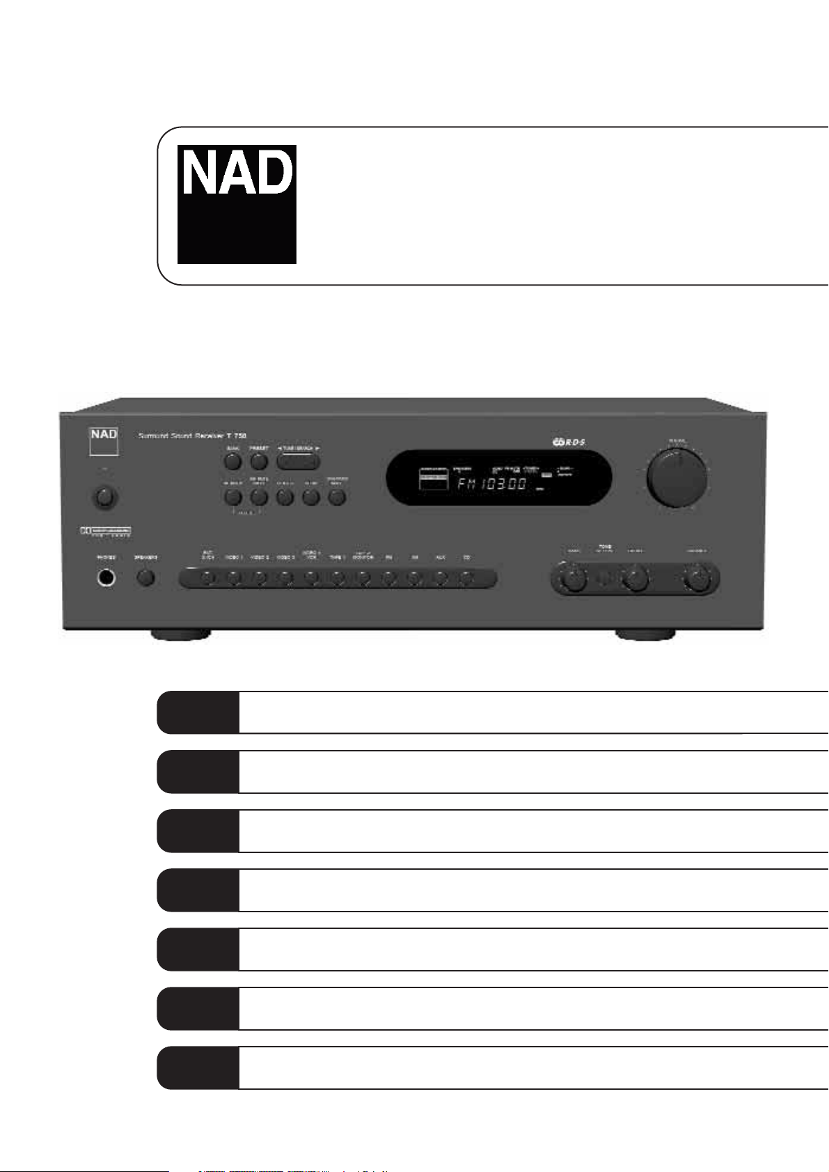
T750
Surround Sound AM/FM Receiver
Owner’s Manual
GB
Manuel d’Installation
F
Bedienungsanleitung
D
Manual del Usuario
E
Manuale delle Istruzioni
I
Manual do Proprietário
P
Bruksanvisning
S
Warning: To reduce the risk of fire or electric shock, do not
expose this unit to rain or moisture.
The lightning flash with an arrowhead symbol within an equilateral
triangle, is intended to alert the user to the presence of uninsulated
“dangerous voltage” within the product’s enclosure that may be of
sufficient magnitude to constitute a risk of electric shock to persons.
The exclamation point within an equilateral triangle is intended to
alert the user to the presence of important operating and
maintenance (servicing) instructions in the literature accompanying
the product.
Do not place this unit on an unstable cart, stand or tripod, bracket
or table. The unit may fall, causing serious injury to a child or adult
and serious damage to the unit. Use only with a cart, stand, tripod,
bracket or table recommended by the manufacturer or sold with
the unit. Any mounting of the device on a wall or ceiling should
follow the manufacturer’s instructions and should use a mounting
accessory recommended by the manufacturer.
An appliance and cart combination should be moved with care.
Quick stops, excessive force and uneven surfaces may cause the
appliance and cart combination to overturn.
Read and follow all the safety and operating instructions before
connecting or using this unit. Retain this notice and the owner’s
manual for future reference.
All warnings on the unit and in its operating instructions should be
adhered to.
Do not use this unit near water; for example, near a bath tub,
washbowl, kitchen sink, laundry tub, in a wet basement or near a
swimming pool.
The unit should be installed so that its location or position does not
interfere with its proper ventilation. For example, it should not be
situated on a bed, sofa, rug or similar surface that may block the
ventilation openings; or placed in a built-in installation, such as a
bookcase or cabinet, that may impede the flow of air through its
ventilation openings.
The unit should be situated from heat sources such as radiators,
heat registers, stoves or other devices (including amplifiers) that
produce heat.
The unit should be connected to a power supply outlet only of the
voltage and frequency marked on its rear panel.
The power supply cord should be routed so that it is not likely to be
walked on or pinched, especially near the plug, convenience
receptacles, or where the cord exits from the unit.
Unplug the unit from the wall outlet before cleaning. Never use
benzine, thinner or other solvents for cleaning. Use only a soft
damp cloth.
The power supply cord of the unit should be unplugged from the
wall outlet when it is to be unused for a long period of time.
Care should be taken so that objects do not fall, and liquids are not
spilled into the enclosure through any openings.
This unit should be serviced by qualified service personnel when:
A. The power cord or the plug has been damaged; or
B. Objects have fallen, or liquid has been spilled into the unit; or
C. The unit has been exposed to rain or liquids of any kind; or
D. The unit does not appear to operate normally or exhibits a
marked change in performance; or
E. The device has been dropped or the enclosure damaged.
DO NOT ATTEMPT SERVICING OF THIS UNIT
YOURSELF. REFER SERVICING TO QUALIFIED
SERVICE PERSONNEL
Upon completion of any servicing or repairs, request the service
shop’s assurance that only Factory Authorized Replacement Parts
with the same characteristics as the original parts have been used,
and that the routine safety checks have been performed to
guarantee that the equipment is in safe operating condition.
REPLACEMENT WITH UNAUTHORIZED PARTS MAY RESULT IN FIRE,
ELECTRIC SHOCK OR OTHER HAZARDS.
ATTENTION
POUR ÉVITER LES CHOC ELECTRIQUES, INTRODUIRE LA
LAME LA PLUS LARGE DE LA FICHE DANS LA BORNE
CORRESPONDANTE DE LA PRISE ET POUSSER JUSQU’AU
FOND.
CAUTION
TO PREVENT ELECTRIC SHOCK, MATCH WIDE BLADE OF
PLUG TO WIDE SLOT FULLY INSERT.
If an indoor antenna is used (either built into the set or installed
separately), never allow any part of the antenna to touch the metal
parts of other electrical appliances such as a lamp, TV set etc.
CAUTION
POWER LINES
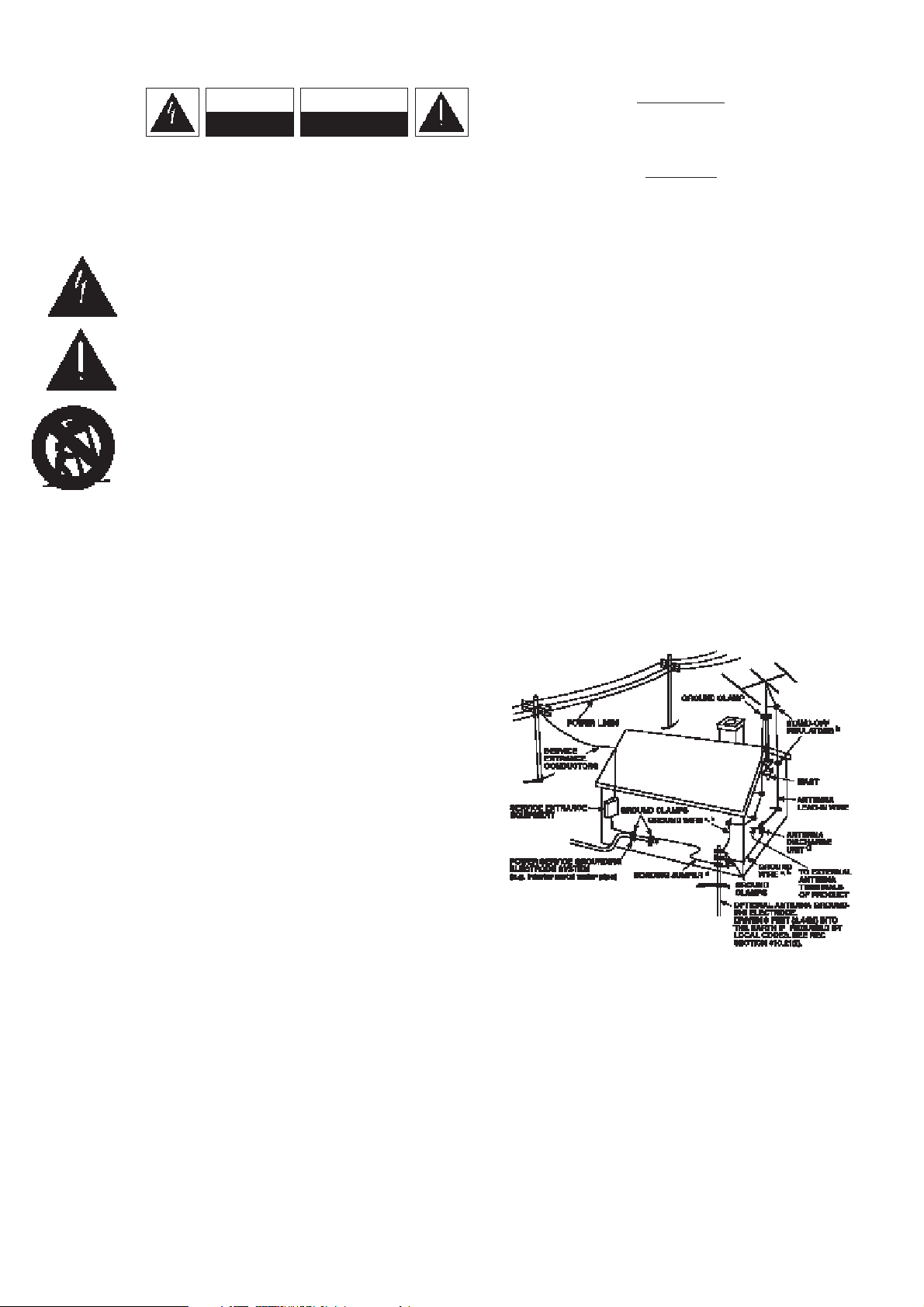
Any outdoor antenna must be located away from all power lines.
OUTDOOR ANTENNA GROUNDING
If an outside antenna is connected to your tuner or tunerpreamplifier, be sure the antenna system is grounded so as to
provide some protection against voltage surges and built-up static
charges. Article 810 of the National Electrical Code, ANSI/NFPA No.
70-1984, provides information with respect to proper grounding of
the mast and supporting structure, grounding of the lead-in wire to
an antenna discharge unit, size of grounding conductors, location of
antenna discharge unit, connection to grounding electrodes and
requirements for the grounding electrode.
a. Use No. 10 AWG (5.3mm2) copper, No. 8 AWG (8.4mm2)
aluminium, No. 17 AWG (1.0mm2) copper-clad steel or bronze
wire, or larger, as a ground wire.
b. Secure antenna lead-in and ground wires to house with stand-off
insulators spaced from 4-6 feet (1.22 - 1.83 m) apart.
c. Mount antenna discharge unit as close as possible to where lead-
in enters house.
d. Use jumper wire not smaller than No.6 AWG (13.3mm2) copper,
or the equivalent, when a separate antenna-grounding electrode
is used. see NEC Section 810-21 (j).
EXAMPLE OF ANTENNA GROUNDING AS PER NATIONAL ELECTRICAL
CODE INSTRUCTIONS CONTAINED IN ARTICLE 810 - RADIO AND
TELEVISION EQUIPMENT.
NOTE TO CATV SYSTEM INSTALLER: This reminder is
provided to call the CATV system installer’s attention to
Article 820-40 of the National Electrical Code that provides
guidelines for proper grounding and, in particular, specifies
that the ground cable ground shall be connected to the
grounding system of the building, as close to the point of
cable entry as practical.
CAUTION
RISK OF ELECTRIC
SHOCK DO NOT OPEN
ATTENTION:
RISQUE DE CHOC ELECTRIQUE
NE PAS OUVRIR
CAUTION: TO REDUCE THE RISK OF ELECTRIC
SHOCK, DO NOT REMOVE COVER (OR BACK). NO
USER SERVICEABLE PARTS INSIDE. REFER SERVICING
TO QUALIFIED SERVICE PERSONNEL.
IMPORTANT SAFETY INSTRUCTIONS
2
3
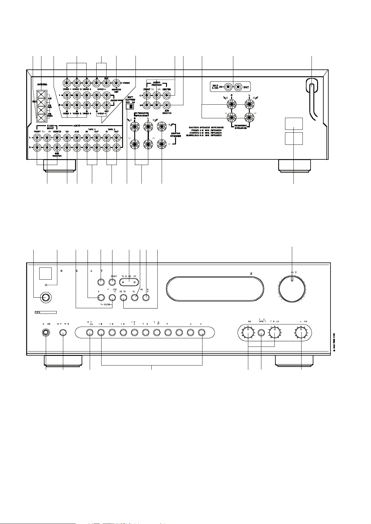
REAR PANEL CONNECTIONS
FRONT PANEL CONTROLS
4
FIGURE 1
FIGURE 2
FIGURE 3
5
FIGURE 5
FIGURE 4

NOTES ON INSTALLATION
Your NAD T750 should be placed on a firm, level surface. Avoid
placing the unit in direct sunlight or near sources of heat and
damp.
Allow adequate ventilation. Do not place the unit on a soft surface
like a carpet. Do not place it in an enclosed position such a
bookcase or cabinet that may impede the air-flow through the
ventilation slots.
Make sure the unit is switched off before making any connections.
The RCA sockets on your NAD T750 are colour coded for
convenience. Red and white are Right and Left audio respectively,
and yellow for NAD Link.
Use high quality leads and sockets for optimum performance and
reliability. Audio RCA leads will function correctly for video
signals, although it is recommended to use dedicated video leads
where possible. Ensure that leads and connectors are not
damaged in any way and all connectors are firmly pushed home.
For best performance, use quality speaker leads of 16 gauge
(1.5mm) thickness or more.
If the unit is not going to be used for some time, disconnect the
plug from the AC socket.
Should water get into your NAD T750, shut off the power to the
unit and remove the plug from the AC socket. Have the unit
inspected by a qualified service technician before attempting to
use it again.
Do not remove the cover, there are no user-serviceable
parts inside.
Use a dry soft cloth to clean the unit. If necessary, lightly dampen
the cloth with soapy water. Do not use solutions containing benzol
or other volatile agents.
REAR PANEL CONNECTIONS
1. 5.1 CHANNEL INPUTS
Inputs for the multi-channel audio signals from an external
decoder, such as a DVD player with integrated Dolby Digital
decoder. Use two twin RCA-to-RCA lead to connect the decoder’s
front left and right ‘Audio Outputs’ to the Front left and right
inputs, and the decoder’s Surround left and right outputs to the
Surround left and right inputs. Use a third twin RCA-to-RCA lead
to connect the decoder’s subwoofer output to the Subwoofer input
and the decoder’s Centre channel output to the Centre channel
input. Make sure you to follow colour coding of the plugs to
ensure that both Centre and Subwoofer are connected correctly,
for instance, use the red plugs at either end to connect the centre
channel and the white plugs for the subwoofer channel.
2. CD INPUT
Input for CD player (analogue audio signal) or other line-level
signal source. Use a twin RCA-to-RCA lead to connect the CD
player’s left and right ‘Audio Outputs’ to this input.
3. AUX INPUT
Input for audio components. Use a twin RCA-to-RCA lead to
connect the audio component left and right ‘Audio Outputs’ to this
input.
4. TAPE 1
Connections for analogue recording and playback to an audio
tape recorder of any type, such as a cassette, reel-reel, DAT, MD
or DCC. Using twin RCA-to-RCA leads, connect to the left and right
‘Audio Output’ of the tape machine to the TAPE 1 IN connectors
for playback. Connect the left and right ‘Audio Input’ of the tape
machine to the TAPE 1 OUT connectors for recording.
5. TAPE 2
Connections for analogue recording and playback to a second audio
tape recorder of any type. Using twin RCA-to-RCA leads, connect to
the left and right ‘Audio Output’ of the tape machine to the TAPE 2 IN
connectors for playback. Connect the left and right ‘Audio Input’ of
the tape machine to the TAPE 2 OUT connectors for recording.
6. VIDEO 1 TO VIDEO 3 (AUDIO)
Inputs for the audio playback from a VCR or other video device
such as a stereo TV, satellite or cable TV receiver or a Laser Disc.
Using twin RCA-to-RCA leads, connect to the left and right ‘Audio
Out’ of the VCR/TV/LD/satellite receiver to these inputs. These
audio inputs are used in conjunction with the composite (line)
video inputs marked VIDEO 1, VIDEO 2 or VIDEO 3. VIDEO 1 to
3 are used for playback only, use VIDEO 4 if you want to connect
a VCR for recording and playback through the T750.
7. VIDEO 4 (AUDIO)
Connections for the audio recording and playback to a VCR or
other video recorder. Using twin RCA-to-RCA leads, connect to the
left and right ‘Audio Out’ of the VCR to the VIDEO 4 IN connectors
for playback. Connect the left and right ‘Audio In’ of the VCR to the
VIDEO 4 OUT connectors for recording. These audio inputs are
used in conjunction with the composite (line) video inputs
marked VIDEO 4 IN and the video outputs marked VIDEO 4 OUT.
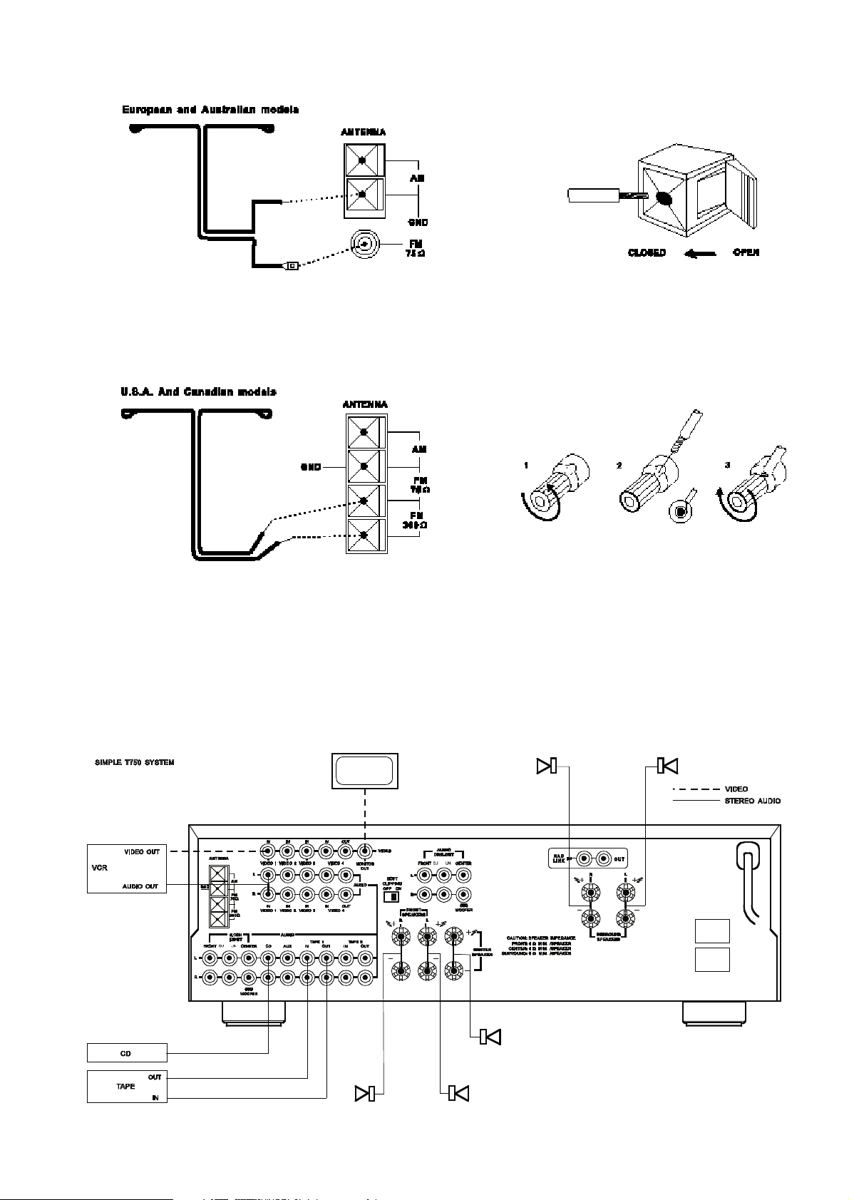
8. AM ANTENNA
An AM loop antenna is supplied with the T750 and is required for
AM reception. Open the clip terminal lever and insert the wire
from the antenna. Closing the lever will lock the wire in place
(Fig. 2). Test various positions for the antenna, but always ensure
the loop is placed vertically for best reception. Placing the antenna
close to large metal items such as metal shelves or radiators may
interfere with reception.
NOTE: When reception is not satisfactory using the supplied AM
loop antenna alone, connection of an external antenna is
recommended. Do not remove the AM loop antenna. Do not
connect anything other than a loop antenna to the AM ANTENNA
terminal. The antenna cable to the loop antenna must not exceed
3 meters.
9. FM ANTENNA
A ribbon wire FM antenna is included and should be connected to
the FM connector at the rear of the unit (Fig. 1). The ribbon aerial
should be mounted on a vertical surface and placed so that it
forms a ‘T’.
Experiment with placement of the antenna to find the position that
gives the best signal strength and lowest background noise. An
inadequate FM signal normally results in high levels of hiss,
especially in stereo, and interference from external electrical
sources. In areas of poor FM reception, the tuner section’s
performance can be improved by using an externally mounted FM
antenna. A qualified aerial installer will be able to advise and fit a
recommended aerial for your reception conditions.
GB
6
NAD T750 Surround Sound AM/FM Receiver

10. SOFT CLIPPING
When an amplifier is driven beyond its specified power output, a
hard, distorted sound can be heard on very loud sounds. This is
caused by the amplifier cutting off or ‘hard clipping’ the peaks of
sound that it was not designed to reproduce. The NAD Soft
Clipping circuit gently limits the output of the system to minimise
audible distortion if the amplifier is over driven.
If your listening involves moderate power levels you may leave the
Soft Clipping switch off. If you are likely to play at high levels that
exceed the amplifier’s power capability, then switch Soft Clipping on.
11. VIDEO 1 TO 3 (VIDEO)
Connection for the Composite video signal input for VIDEO 1,
VIDEO 2 or VIDEO 3 . Using a RCA-to-RCA lead, connect the ‘Video
Out’ of the VCR, TV, Laser Disc or satellite/cable unit. VIDEO 1 to
3 can be used for video playback only. Use VIDEO 4 if you want to
connect a VCR for recording and playback through the T750.
12. VIDEO 4 (VIDEO)
Connection for the Composite video signal input for VIDEO 4. Using
a RCA-to-RCA lead, connect the ‘Video Out’ of the VCR to VIDEO 4
IN for playback. Connect VIDEO 4 OUT to the ‘Video In’ of the VCR
to copy video signals from VIDEO 1, VIDEO 2 or VIDEO 3.
13. MONITOR OUT
Composite video output for connecting a TV or Video Monitor to
view video sources connected to VIDEO 1 to VIDEO 4. Using a
RCA-to-RCA lead, connect the ‘Video Line In’ on the TV or monitor
to the MONITOR OUT. This output can also be used as an
additional recording output if required. Video monitoring must
then be done via the output of the video recorder.
14. AUDIO PRE-OUTS
The NAD T750 receiver has five power amplifiers built-in to power
all the speakers connected to it (Left, Right, Centre, Left Surround,
Right Surround). It is also possible to use the T750 as a preamplifier to drive external power amplifiers. This way, you use all
the control functions the T750 provides, such as input select,
surround mode, volume, tone controls, etc., but the external
power amplifier actually powers the speaker connected it instead
of the T750’s integrated power amplifier for that channel.
Connect the RCA-to-RCA leads from the Front left and Right, Centre,
and/or Surround Left and Right Audio pre-out connectors to the
external amplifiers. Connect speakers to the external amplifiers.
NOTES: Never connect the T750’s speaker outputs and the
speaker outputs of an external amplifier to the same speakers.
Make sure the T750 and the power amplifiers it will be connected
to are switched off. With volume turned down to a low level,
switch power on only after all connections have been made.
15. SUB WOOFER OUT
Unlike for the full range five channels as described above, there is
no power amplifier built-in for an additional subwoofer. The
Subwoofer pre-out allows for connection to a sub-bass speaker
system with its own power amplifier.
16. FRONT SPEAKERS
These speaker outputs are switched on and off by using the
SPEAKERS button on the front panel.
Connect the right speaker to the terminals market ‘R +’ and ‘R -’
ensuring that the ‘R +’ is connected to the ‘+’ terminal on your
loudspeaker and the ‘R -’ is connected to the loudspeaker’s ‘-’
terminal. Connect the terminals marked ‘L +’ and ‘L -’ to the left
speaker in the same way.
Always use heavy duty (16 gauge; 1.5mm or thicker) stranded
wire to connect loudspeakers to your T750.
Unscrew the speaker terminal’s plastic bushing. Insert the pin or
bare cable end into the hole of the terminal and then secure the
cable by tightening down the terminal’s bushing (Fig. 3).
To avoid any danger of bare metal from the speaker cables
touching the back panel or another connector, ensure that there
is only 1/2” (1.27cm) of bare cable or pin and no loose strands
of speaker wire.
CAUTION: This unit is designed to produce optimum sound
quality when speakers with impedances within the set’s ranges are
connected. Please check the following information and choose
speakers with the correct impedances for the connections.
FRONT SPEAKERS: 4 ohms min. per speaker
CENTRE SPEAKER: 4 ohms min.
SURROUND SPEAKERS: 6 ohms min. per speaker
17. CENTER SPEAKER
This connects the centre loudspeaker that is used when the T750
is operated in Dolby* Pro Logic, Dolby 3 stereo mode or with the
5.1 Ch. input selected. Connect the ‘Center +’ to the ‘+’ terminal
on your centre loudspeaker and the ‘Center -’ to the loudspeaker’s
‘-’ terminal.
Strip 1/2” (1.27cm) of insulation from the end of the speaker
cable and twist the bare wires so that there are no loose strands.
These terminals operate in the same way as the Front Speaker
terminals. These speakers operate in conjunction with the Front
Speakers and are switched on and off by using the SPEAKERS
button on the front panel.
18. SURROUND SPEAKERS
This connects the rear loudspeakers that are used when the T750
is operated in Dolby Pro Logic, Hall modes or with the 5.1
Ch. input. Connect the right Surround speaker to the terminals
market ‘R +’ and ‘R -’ ensuring that the ‘R +’ is connected to the
‘+’ terminal on your loudspeaker and the ‘R -’ is connected to the
loudspeaker’s ‘-’ terminal. Connect the terminals marked ‘L +’
and ‘L -’ to the left speaker in the same way.
Strip 1/2” (1.27cm) of insulation from the end of the speaker
cable and twist the bare wires so that there are no loose strands.
These terminals operate in the same way as the Front Speaker
terminals. These speakers operate in conjunction with the Front
Speakers and are switched on and off by using the SPEAKERS
button on the front panel.
19. NAD-LINK IN OUT
The NAD-Link connector is used to pass commands from other
units fitted with NAD-Link connectors. This allows centralised
control of a complete system, and also allows some of the basic
functions of other NAD components (such as a CD player or
cassette deck) also equipped with NAD-Link to be controlled with
the receiver’s remote control. To function with such other units,
connect the T750’s NAD-Link Out to the NAD-Link In on the other
unit. NAD-Link connectors can be daisy-chained, IN to OUT, so
that a whole system can be controlled from the remote control
facilities of one unit.
GB
7
* Manufactured under license from Dolby Laboratories. “Dolby”, “Pro Logic” and the double-D symbol are trademarks of Dolby Laboratories. Confidential Unpublished Works.
©1992-1997 Dolby Laboratories, Inc. All rights reserved.

20. AC OUTLETS
(120V NORTH AMERICAN VERSIONS ONLY)
The AC power cords of other units in the audio system can be
connected directly to the T750’s AC outlets. If another stereo
component is plugged into the SWITCHED AC outlet, power will be
supplied to that component only when your T750 is turned on.
If another stereo component is plugged into the UNSWITCHED AC
outlet, power will be supplied whether your T750 is on or off.
NOTE: The AC outlets should be used with units with a
COMBINED power consumption of no more than 120 Watts.
21. AC POWER CORD
After you have completed all connections to the amplifier, plug the
AC line cord into a “live” wall socket.
FRONT PANEL CONTROLS
POWER, SPEAKERS AND HEADPHONE FUNCTIONS
1. POWER
Press the POWER button to switch the receiver to its ‘Stand-by’
mode. The Stand-by indicator (No. 2) over the power button will
light up. On the front panel, press any of the input selector buttons
(No. 6) to switch to receiver on. From the remote control, press
the green Stand-by button (located just over the Speakers button)
to switch the unit on. The display will light up indicating which
input was selected; the Stand-by indicator will extinguish.
Pressing the POWER switch again will turn the unit OFF completely.
The NAD T750 receiver uses a memory back-up system to store
surround sound trim settings and Preset station information for the
tuner section. This information is retained for several weeks, even
the unit is switched off completely or unplugged.
REMOTE CONTROL
STAND-BY button (green, No. 1 on remote control drawing):
Press this button to switch the unit from operating to the Stand-by
mode and vice versa: Press this button again to switch to unit on from
Stand-by; the last selected source will be indicated in the display.
NOTE: Stand-by mode is indicated by the Stand-by indicator (No. 2) just
over the green POWER button on the front panel (No. 1) In Stand-by
mode the T750 uses very little power. However, it is recommended that
you switch the unit totally off if it is not going to be used for more than
a couple of days. Switch off completely by pressing the POWER button
on the front panel (No. 1), all lights will extinguish. Press this button to
switch the unit on. To switch the unit off, press this button again.
2. STANDBY
This green LED will light up when the receiver is switched On, but
in Stand-by mode. Refer to section 1 in this chapter for more
information. The LED will also light up when the receiver receives
a remote control command from the supplied handset.
3. HEADPHONE SOCKET
A 1/4” stereo jack socket is supplied for headphone listening. The
socket has its own amplifier which will drive conventional
headphones of any impedance. The volume, tone and balance
controls are operative for headphone listening. Use a suitable
adapter to connect headphones with other types of connectors
such as 3.5mm stereo ‘personal stereo’ jack plugs.
Press the Speakers button (No. 4) to turn off all speakers for
headphone listening only.
NOTE: Listening at high levels can damage your hearing.
4. SPEAKERS
The SPEAKERS button turns the speakers connected to the FRONT,
CENTRE and SURROUND SPEAKERS terminals on or off. When the
speakers are turned on, the SPEAKERS indicator lights up.
Press Speakers to switch off all speakers for headphone listening
(No. 3) without the speakers playing simultaneously.
NOTE: Always turn the volume down when engaging or
disengaging Speakers.
INPUT AND MONITOR SELECTORS
5. EXT. 5.1CH
Selects the multi-channel output signal from the DVD player or
external decoder source connected to the 5.1 Ch. input as the
active input.
NOTES: The Surround mode button (No. 16) does not have any
effect in this mode.
No audio signal is available from the Tape 1, Tape 2 and Video 4
outputs when the Ext. 5.1Ch, input has been selected.
6. VIDEO 1 TO VIDEO 4, TAPE 1, TAPE 2
MONITOR, FM, AM, AUX, CD
These buttons select the active input to the T750 and the signal sent
to the loudspeakers and the Tape, Video 4 and TV monitor outputs.
The name of the Input and Surround Mode will be shown in the
Display Panel.
VIDEO 1 to VIDEO 3 Selects the signal from stereo
TV/Satellite/Cable receiver or Laser Disc connected to VIDEO 1, 2
or 3 as the active input. Video 1,2 or 3 is shown in the Display
Panel when these are selected.
VIDEO 4 VCR Selects the VCR connected to VIDEO 4 as the active
input. Video 4 is shown in the Display Panel when selected.
TAPE 1 Selects Tape 1 as the active input.
TAPE 2 MONITOR Selects the output from a tape recorder when
playing back tapes or monitoring recordings being made through
the Tape 2 sockets. Press the Tape 2 button once to select it and
again to return to the normal input selection.
Tape 2 is a Tape Monitor function which does not override the
current input selection. For example, if the CD is the active input
when TAPE 2 is selected, then the CD signal will continue to be
selected and sent to both the TAPE 1, TAPE 2 and Video 4 OUTPUT
sockets, but it is the sound from recorder connected to Tape 2
that will be heard on the loudspeakers. When Tape 2 Monitor is
selected, “TAPE 2” is indicated in the alphanumeric section of the
display for 3 seconds before it defaults to indicating the active
input again. The box just over the alphanumeric section indicating
“T-2 MONITOR” will remain lit until Tape 2 is disengaged again.
FM Selects FM radio. FM is also automatically selected when an
FM Preset is selected.
AM Selects AM radio. AM is also automatically selected when an
AM Preset is selected.
AUX Selects the auxiliary audio component as the active input.
CD Selects the CD as the active input.
VOLUME, BALANCE AND TONE FUNCTIONS
7. VOLUME
The VOLUME control adjusts the overall loudness of the signals
being fed to the loudspeakers. It is motor driven and can be
adjusted from the remote control handset using the Master
Volume or button. The Volume control does not affect
recordings made using the Tape and Video 4 outputs but will affect
the signal going to the Pre-amp output (Audio Pre Out).
GB
8

On the remote control handset, press the Mute Button to
temporarily switch off the sound to the speakers and headphones.
Mute mode is indicated by “AUDIO MUTE” flashing in red in the
display area. Press Mute again to restore sound. Mute does not
affect recordings made using the Tape and Video 4 outputs but will
affect the signal going to the Pre-amp output (Audio Pre Out).
8. BASS & TREBLE CONTROLS
The T750 is fitted with BASS and TREBLE tone controls to adjust
the overall tonality of your system.
The 12 o’clock position is ‘flat’ with no boost or cut and a detent
indicates this position. Rotate the control clockwise to increase
the amount of Bass or Treble. Rotate the control anti-clockwise to
decrease the amount of Bass or Treble. These controls affect the
Left and Right Front speakers only. In Dolby Pro Logic, Dolby 3
Stereo, Hall modes or the EXT. 5.1CH input selected, the Centre
and Surround speakers maintain a ‘flat’ response, regardless of
the tone control settings. The Tone controls do not affect
recordings made using the Tape or Video line outputs but will
affect the signal going to the Pre-amp outputs (Audio Pre Out).
9. TONE DEFEAT
The Tone Defeat switch by-passes the tone control section of the
T750. If the Tone Controls (No. 8) are not normally used and left
in the 12 o’clock position, then it is advisable to switch out the
Tone Control section altogether by using this switch. In the ‘out’
position, the Tone Control circuits are active, pushing the Tone
Defeat switch in bypasses the Tone Control section.
10. BALANCE
The BALANCE control adjusts the relative levels of the Left and
Right Front speakers. The 12 o’clock position provides equal level
to the Left and Right channels. A detent indicates this position.
Rotating the control clockwise moves the balance towards the
right. Rotating the control anti-clockwise moves the balance to the
left. The BALANCE control does not affect recordings made using
the Tape or Video line outputs but will affect the signal going to the
Pre-amp outputs (Audio Pre Out).
TUNER
11. TUNE/SEARCH AND
The function of these buttons depends on the tuning mode
selected with the Preset button (No. 12). The Preset button toggles
between the two operation modes:
a) Preset mode (indicated in the display area): Press the
button to scroll to a lower number Preset; press the button
to scroll to a higher Preset number. This is a “wrap-around”
function, so that going from the highest number Preset the tuner
will go to the lowest Preset number when is pressed.
a) Tune mode: Press the or for more than 1/2 second to
engage automatic tuning respectively up or down the frequency
band. The tuner will search automatically for the first reasonably
strong radio station, where it will stop. Press the Tune/Search
button again for 1/2 second to start searching again.
NOTE: Automatic tuning is only available on FM.
By briefly tapping the or you can engage manual tuning
respectively up or down the frequency band for precise tuning to a
specific frequency. With each successive tap of the keys, the tuner will
take 0.05 or 0.1 MHz steps (depending on version) on FM so you can
accurately tune into the desired frequency. For AM the tuning steps
can be 9 kHz or 10 kHz, depending on the version of your T750. This
tuning mode can also be useful when trying to receive a radio station
which is too weak for the auto search mode. When tuned accurately
to a station, “ TUNED ” will light up in the display.
With stations carrying RDS information, the station’s RDS name is
displayed, Program Service (PS; normally the station’s calling
letters, BBC R3, for instance).
Refer also to chapter “Storing AM and FM stations” for additional
information.
NOTE: The 120V versions (North America) do not have RDS
(Radio Data System).
12. PRESET
The Preset button toggles between the Preset and Tune mode.
When Preset mode is selected, “PRESET” lights up in the display
area.
Up to 30 Presets, either AM or FM, can be stored in three Preset
Banks, which can contain up to 10 Preset stations each. The
Preset number is shown in the Display Panel.
Refer also to section 11 and chapter “Storing AM and FM stations”
for additional information.
13. BANK
Pressing Bank switches between the T750’s three Preset Memory
Banks (A, B or C). Each of these banks can hold up to 10 Preset
stations. These Banks can contain a mix of AM or FM stations
each. The Bank selected is shown in the Display Panel. You can
use the banks to sort your Presets, for instance by station type
(Bank A for rock/pop; Bank B for Classical music; Bank C for
Jazz).
Refer also to chapter “Storing AM and FM stations” for more
information.
The remote control handset also has a Bank button and performs
the same function.
14. MEMORY
The Memory button is used to store stations into the three Preset
Memory Banks. Used in conjunction with the Tune/Search (No.11)
buttons. When Memory is active, the Preset number flashes and the
red ‘MEMORY’ indicator is shown in the Display Panel.
Refer also to chapter “Storing AM and FM stations” for more
information.
15. FM MUTE/MODE
This button combines two functions; it switches the tuner from
Stereo to Mono and disengages the muting circuitry at the same time.
The muting circuit will mute the tuner in between radio stations
when searching or tuning. This way the tuning noise is avoided.
Very weak radio station signals however may be suppressed by the
muting circuit. if such a very weak station is in stereo it will have
a high level of background hiss. Switching to Mono Mode and
disengaging the muting circuit by depressing the FM MUTE/MODE
button will allow the station to be heard and will cancel most or
all of this background noise.
In normal operation the mute circuit is engaged, the display
indicates “FM MUTE ON”. Press the FM Mute/Mode button to
disengage the muting circuit and switch from stereo to mono
reception. The status of FM Mute/Mode is indicated in the display.
Also, “STEREO” will extinguish if a stereo broadcast was received.
Press the FM Mute/Mode switch again to return to Auto Stereo FM
operation.
GB
9

SURROUND FUNCTIONS
16. SURROUND MODE
The Surround Mode button scrolls through the T750’s surround
modes: Dolby Pro Logic, Dolby 3 Stereo, Hall and By-Pass
(normal Stereo).
Dolby Pro Logic and Dolby 3 Stereo both decode the surround
sound signals encoded in movie sound tracks from video or TV. To
decode correctly, the video or TV signal must be of a Dolby
Surround or Dolby Stereo soundtrack and coming from a stereo
VCR, TV or satellite/cable receiver.
In the Dolby Pro Logic the rear Surround speakers are also
activated. Use of a centre channel speaker is optional (set with the
Centre button No. 17).
In the Dolby 3 Stereo mode, the rear Surround speakers are
inoperative; the centre channel however is activated in this mode.
Dolby 3 Stereo can be a good alternative to Pro Logic if it isn’t practical
or if space doesn’t allow for the installation of Surround speakers.
For more information refer also to the chapter “Setting up the
Surround System” and appendix “A short guide to Surround Sound”.
In the HALL mode, a realistic level of ambience of surround sound
is added to a normal stereo source such as a CD or FM radio. The
centre channel is inoperative in this mode.
BY-PASS switches to normal Stereo operation.
The selected mode is displayed in the main area of the Display
Panel for 3 seconds and is continuously shown in Surround Mode
area of the Display Panel.
As an additional convenience feature, your T750 memorises
which surround mode you have used with the given input
selection. When you next select that input, your T750 will
automatically choose the same Surround mode again. If you
normally use Dolby Pro Logic mode on the Video 1 and Video 2
inputs, Dolby 3 Stereo mode on the Video 3 input, Hall mode on
FM, and By-Pass (Stereo) on the others, pressing the Input
Selector will automatically default to the right Surround mode
without having to separately press the Surround Mode button.
NOTES: An external source such as a decoder or DVD player with
a decoder built-in (Dolby Digital, DTS* for instance) can be
connected to the 5.1Ch input (No. 5). When the EXT 5.1 CH. input
is selected, no other surround modes are available, so
“SURROUND MODE” extinguishes in the display panel.
17. CENTER
Selects the type of centre speaker used on the main speaker
system. The Center button is only operative with Dolby Pro Logic
or Dolby 3 Stereo selected.
In Dolby Pro Logic mode NORMAL, WIDEBAND, PHANTOM are the
available options. In Dolby 3 Stereo mode NORMAL and WIDEBAND
are available. Select the mode appropriate to the T750’s set-up
The NORMAL mode is used when the centre speaker is smaller than
the front left and right speakers. This mode produces a true centre
image with the very low frequencies (below 70 Hz) filtered out.
The WIDEBAND mode is used when the centre speaker is the same
type as the front left and right speakers. This mode produces a
true centre image with a full frequency range and no low
frequency filtering.
The PHANTOM mode is used when there is no centre speaker
installed. The T750 places the centre information equally on the
left and right front speakers so producing a ‘Phantom’ central
sound image.
The selected Center Mode is displayed for 3 seconds in the main
area of the Display Panel. It is stored in the T750’s memory and
will be automatically recalled each time the unit is switched on.
18. DELAY
Selects the amount of delay applied to the surround speakers
when the T750 is used in DOLBY PRO LOGIC or HALL modes.
Pressing the DELAY button steps the Delay times in 5mS steps from
5mS to 30mS for Hall mode and from 15mS to 30mS for Dolby
Pro Logic mode. Separate delay times can be stored for DOLBY
PRO LOGIC and HALL modes and are held in the T750’s memory.
They are automatically recalled each time the DOLBY PRO LOGIC
or HALL mode is selected.
This function can be altered only when the T750 is in DOLBY PRO
LOGIC or HALL Mode.
Refer also to the chapter “Setting up the Surround Sound system”
for more information.
STORING AM & FM STATIONS
TO STORE A PRESET
• Tune to the radio station you wish to enter into a Preset (refer
to chapter “Front Panel Controls” section 11). If the station is
transmitting RDS information, the RDS indicator will light up
and station initials will be shown in the Display Panel. If a nonRDS station is found, then just the frequency will be shown.
• To store that station as a Preset, press Memory (No. 14). The
Memory indicator will be displayed and the Preset section will
flash in the Display Panel.
• Press Bank (No. 13) to select which of the three Banks of
Presets (A, B or C) you want to store the station into. Press
either the Tune/Search or button to select which
Preset number you wish to assign to the station (from 1 to 10),
shown as a flashing number in the Display Panel, and then
press Memory (No. 14) again. The Memory light in the Display
Panel will go out and the station is now stored in your NAD
T750’s memory.
To exit the Memory mode without storing a station, leave all the
tuner controls untouched; the Memory mode will automatically
cancel itself after 8 seconds. The Memory Presets have a memory
back-up, so they will remain stored for several weeks even if the
Receiver is switched off or unplugged from the mains supply.
NOTE: You can enter a new station into an unused Preset or overwrite an existing programmed Memory Preset. By doing this you
will replace the radio station previously held on that Preset
number.
RECALLING A PRESET STATION
• To select a Preset station, select the Preset mode by pressing the
Preset button (No. 12) until “PRESET” lights up in the display.
• By pressing the Bank button (No. 13) select which Bank of
Presets you want to use (A, B or C, indicated in the display).
• Press either the Tune/Search or buttons (No. 11)
until the right Preset is found and shown in the Display Panel.
NOTE: Any unused Presets will be skipped and it is not possible
to select a Bank unless it has at least one Preset stored into it.
NOTE: The 120V versions (North America) do not have RDS
(Radio Data System).
GB
10
* “DTS” is a trademark of Digital Theater Systems
DELETING A STORED PRESET:
You can empty a Preset by deleting the stored information:
• Select the Preset to be emptied.
• Press the Memory button (No. 14), hold it down and press the
FM Mute/Mode button (No. 15). The Preset will then be
deleted and ‘—’ appears as the Preset number.
You can also store a new station into a used Preset, by simply
going through the Preset storing process and placing a new station
over the existing one.
REMOTE CONTROL
The T750’s Remote Control handles all the key functions of the
T750 and has additional controls to remotely operate NAD Cassette
and CD machines. It will operate up to a distance of 16ft (5m).
Alkaline batteries are recommended for maximum operating life.
Two AAA (R 03) batteries should be fitted in the battery
compartment at the rear of the Remote Control handset. When
replacing batteries, check that they have been put in the right way
round, as indicated on the base of the battery compartment.
The EXT 5.1, Video 1 to 4, Tape 1, 2, Aux and CD Input selector,
Speaker, Bank and Surround Mode buttons perform the same
function as those on the front panel of the T750. There are a few
differences and extra functions with the remote control handset
however (numbers refer to fig. 4):
1. STAND-BY
Press this green button to switch the unit from operating to the
Stand-by mode and vice versa: Press this button again to switch the
unit on from Stand-by; the last selected source will be indicated in
the display.
2. SLEEP
Press SLEEP to make the T750 automatically switch off after a
preset number of minutes. Pressing the SLEEP button once will set
the sleep time to 90 minutes, after which the T750 will
automatically switch off into Standby mode. Sleep mode and the
Sleep delay is shown on the Display Panel. To adjust the Sleep
Delay, hold down the SLEEP button. This will reduce the sleep time
in 10 minute increments, as shown in the Display Panel. To cancel
the Sleep mode, continue pressing the SLEEP button until the
source name appears in the Display Panel. Pressing the POWER or
STANDBY button will also cancel the Sleep mode.
3. MUTE
Press the MUTE button to temporarily switch off the sound to the
speakers and headphones. Mute mode is indicated by “AUDIO
MUTE” flashing in red in the display area. Press MUTE again to
restore sound. Mute does not affect recordings made using the
Tape outputs but will affect the signal going to the Audio Pre-outs.
4. TUNER
Whereas the T750’s front panel has separate buttons for AM and
FM, the remote control has a single Tuner button. The tuner
section can be activated by pressing Tuner. The tuner button will
select the tuner as the active input and revert to the last station
tuned to on either the AM or FM band.
5. CHANNEL SELECT
Press the Ch. Select button to address the Centre, Left Surround or
Right Surround channels for adjustment of volume trims relative
to Left and Right channels. Each successive press of the button
causes the T750 to scroll to the next channel: Centre ➜ Right
Surround ➜ Left Surround ➜ Centre, etc. The display indicates
which channel is selected. Within the default time of 8 seconds,
use either the Level or (No. 7) to change relative
volume level for the desired channel.
Refer also to the chapter “Setting up the Surround Sound system”
for more information.
6. LEVEL
With the Level or (No. 7) buttons the relative volume
level trims for Centre, Left and Right Surround channels can be
adjusted. Press the Channel Select button (No. 5) to select the
channel for which you wish to adjust the level.
Refer also to the chapter “Setting up the Surround Sound system”
for more information.
7. TEST
Pressing the Test button engages the Test generator which
generates a noise signal that scrolls to each of the speaker
channels (Left ➜ Centre ➜ Right ➜ Left & Right Surround ➜
Left ➜ etc. for Dolby Pro Logic; Left ➜ Centre ➜ Right ➜ Left
➜etc. for Dolby 3 Stereo), so that each can be adjusted for equal
loudness at your listening position. The Display Panel shows
which speaker is being fed with the test signal.
8. MASTER VOLUME
Master Volume or respectively increases or decreases
the Volume setting for all speakers. The motorised Volume Control
on the front panel will indicate the level set. The VOLUME control
does not affect recordings made using the Tape and Video 4
outputs but will affect the signal going to the Pre-amp output
(Audio Pre Out).
9. PRESET OR
The Preset or buttons will allow direct selection of the
desired Preset without having to select Preset Tuning mode first.
Other than the commands relating to the NAD T750 receiver itself,
there are other buttons which will operate most NAD CD players
and Cassette decks equipped with NAD Link.
10. CD PLAYER CONTROL
(for use with NAD CD Player)
engages Pause
engages Stop
engages Play or toggles between Play and Pause
or engages Track skip; Press once to respectively go to
the next track or to return to start of current or previous track.
DISC Go to next disc (for NAD CD changers).
11. CASSETTE DECK CONTROL
(For use with single (DECK B) or double transport (A and B) NAD
Cassette Decks)
or engages Forward Play or Reverse Play.
Record / Pause. Press to put cassette deck into record-
pause. Press Play to start recording.
Stops Play or Recording.
engages Rewind.
engages Fast Forward.
GB
11

NOTES: Direct sunlight or very bright ambient lighting may affect
the operating range and angle for the remote control handset.
The infrared remote control command receiver, located on the far
left of the display window, receives commands from the remote
control. There must be a clear line-of-sight path from the remote
control to this window; if that path is obstructed, the remote
control may not work.
SETTING UP THE SURROUND SYSTEM
To work at its best, the output levels of the T750’s surround
facilities need to be adjusted so that there is an even balance of
sound from all the speakers in the system.
The Delay time for the Surround speakers also needs to be
correctly set for your normal listening position. Refer to the
section “Setting the Surround Delay” in this chapter for more
information.
The adjustment of speaker levels is done using the Test (No. 7),
Channel Select (No. 5) and Level (No. 6) functions on the Remote
Control. It is important first to correctly phase all the speakers in
the system. Check that the positive (+) terminals of the T750
speaker outputs are connected to the positive (+) connector on
the each of the speakers. Refer also to the section “Speaker
Phase” in the chapter “Appendix” for additional information.
Before starting the set-up procedure, ensure that the Centre
(No. 17) mode is set correctly for your speaker configuration. Set
the BALANCE control to the position normally used for stereo
sources (usually the 12 o’clock position).
• With the speakers connected and the VOLUME turned down to
zero, select the Dolby Pro Logic or Dolby 3 Stereo mode using
the Surround Mode button (No. 16) and press Test on the
Remote Control (No. 7 in fig. 4). This generates a test signal
that scrolls to each of the speaker channels (Left ➜ Centre ➜
Right ➜ Left & Right Surround ➜ Left ➜ etc. for Dolby Pro
Logic; Left ➜ Centre ➜ Right ➜ Left ➜ etc. for Dolby 3
Stereo), so that each can be adjusted for equal loudness at
your listening position. The Display Panel shows which
speaker is being fed with the test signal.
Turn the Volume (No. 7; No. 8 in fig. 4) up until the signal is
moderately loud through the Left and Right Front speakers.
• Press the CH.Select button (No. 5 in fig. 4) on the remote
control until “CENTRE” appears in the display. Within the 5s
default time, press the Level or button on the
Remote Control (No. 6 in fig. 4) to increase or decrease the
Centre speaker’s loudness so that it matches the levels being
produced by the Left and Right speakers. The relative level of
the Centre channel is shown in the Display Panel and can be
changed in dB steps.
• In Dolby Pro Logic or Hall mode Press the CH.Select button
(No. 5 in fig. 4) on the remote control until “R-SUR.” appears
in the display to adjust the Right Surround speaker. Again,
within the 5s default time, use the Level or buttons
to set the level so that it matches the levels produced by the Left
and Right Front speakers.
• Press the CH.Select button (No. 5 in fig. 4) on the remote
control until “L-SUR.” appears in the display to adjust the Left
Surround speaker. Repeat the same procedure as described
above to match the levels produced by the Left and Right Front
speakers
A more accurate adjustment can be made using a sound level
meter, if available. Set the meter to ‘Slow’ and ‘C-weighted’ modes
and re-check the settings with the meter placed in several different
positions in the general listening area.
If a Sub-Woofer is used on the system, adjust the Sub-Woofer’s level
control so that it is audible, but does not dominate the sound. SubWoofer levels can be later fine-tuned using programme material.
The Level settings are stored in the T750’s memory. They are
automatically recalled when the unit is switched on.
NOTES: In Dolby 3 Stereo Surround mode the Surround channels
are inoperative. Only the Centre channel can be accessed to adjust
in level.
In Dolby Pro Logic with Phantom Centre mode selected, and Hall
Surround Modes the Centre channel is inoperative. Only the Left
Surround and Right Surround channels can be accessed to adjust
in level.
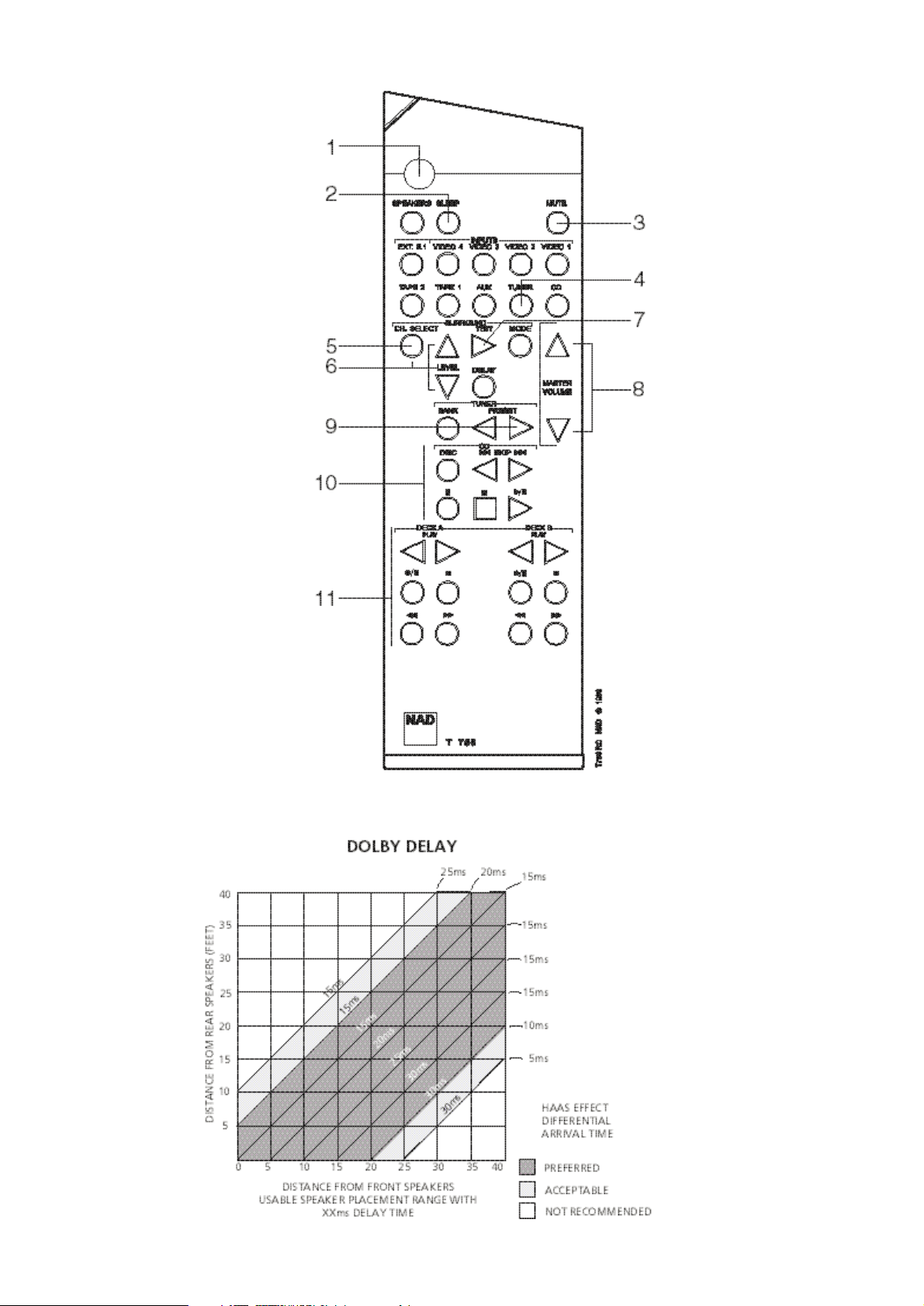
SETTING THE SURROUND DELAY
Because the Surround speakers are usually closer to the listener
than the Front speakers, there is a tendency for the ear to localise
sounds to the rear, because the ear takes most notice of the
sounds that arrive at the head first.
To resolve this problem, the Dolby Pro Logic circuit includes a
Surround delay. This ensures sound coming from the surround
speakers always arrives at the listener’s ears after the sound from
the front speakers.
The exact amount of delay required depends on the relative
distances between the Front and Surround speakers and the
listening position in the room.
First make a note of the distance between the surround speakers and
the listening position. Now make a note of the distance between the
front speakers and the listening area. Note where the two distances
intersect this will give the correct Delay setting (see fig. 5).
To adjust the Delay setting, put the T750 into Dolby Pro Logic
mode and press DELAY on the front panel (No. 18) or the Remote
Control. Continue pressing DELAY until the correct value is shown
in the Display Panel.
The Delay settings are stored in the T750’s memory. They are
automatically recalled when the unit is switched on.
APPENDIX
A SHORT GUIDE TO SURROUND SOUND
Since the middle of the 1970’s, film companies have been making
movies in increasing numbers in Dolby Stereo, the four channel
surround sound system available in most movie theatres today.
Fortunately it is a simple operation to take the film’s Dolby Stereo
soundtrack and place it on a stereo VHS videotape, Laser Disc or
Video-CD. The sound track does require some conversion for
home use, and the domestic version of Dolby Stereo is called
Dolby Surround.
Today, most video copies of movies also contain this surround
information originally designed for the movie theatre. As well as
videos, Dolby Surround is also being used on TV programmes and
on music CDs, and all of these can be decoded using your T750.
Unlike the quadraphonic systems which tried to produce pinpoint sounds coming from all directions, Dolby Surround is
designed to give you a clear front image with the Surrounds filling
the room with atmospheric sound.
GB
12

For best results, the Surround loudspeakers should not beam the
sound directly at the listener. One way of achieving this is to use
‘dipole’ Surround speakers which aim the sound down the walls
rather than directly into the room. An alternative is to use standard
small loudspeakers for Surrounds, but not to point them directly
at the listening position. It is always worth experimenting with
various Surround speaker positions to see which works best in
your room.
With the recent advent in digital technology, various new surround
systems have emerged. Best known are Dolby Digital and DTS,
both are sometimes referred to as 5.1 formats (5 independent,
full range channels and 1 “Effects channel” for bass). The Dolby
Digital and/or DTS formats can be found on some Laser Discs and
DVDs, for instance.
Using the NAD T750’s Ext. 5.1Ch. input, the decoded, analogue
audio Dolby Digital or DTS can be directly connected. Already
there are DVD players available with integrated Dolby Digital
decoder, which will connect directly to the T750.
SPEAKER PLACEMENT
Placement of the speakers in a Dolby Pro Logic surround system
plays an important role in the performance of the system.
FRONT SPEAKERS
The front speakers should be placed with the left and right
speakers evenly spaced either side of the TV screen. The centre
speaker should be placed underneath or above the TV monitor so
that dialogue is localised close to the TV image.
SURROUND SPEAKERS
The surround speakers are used to create a diffuse room-filling
atmospheres rather than pinpoint sound effects. Surround
speakers should be wall or shelf mounted fairly high up either on
the side walls, rear wall or in the rear corners. Speakers can be
mounted facing sideways or upwards to increase the diffusing
effect by bouncing the sound off the walls and ceiling before it
reaches the listener.
SUB-WOOFER
The very low frequency sounds produced by the sub-woofer are
difficult to localise so the Sub-woofer can be placed virtually
anywhere in the room. Placing Sub-woofers against walls or in
corners will increase the amount of bass produced in the room.
WHY HAVE A CENTRE SPEAKER?
The Dolby Pro Logic decoder produces three separate outputs for
the Front signals - left, centre and right. On most soundtracks, the
sound effects and music are spread across all three front channels
but the dialogue is mainly fed to the centre channel only.
Using a separate centre channel speaker will allow the dialogue to
cut through even the biggest sound effects and musical scores.
Having the sound spread across three front speakers also stabilises
the stereo image, making the usable listening area much bigger.
If you are using the T750 with only two front speakers, setting the
Centre mode (No. 17) to PHANTOM will place the centre
information on both the left and right speakers. This creates the
impression of a centre channel sound source.
For best results, you should consider using a centre speaker.
Ideally it should be the same type as the left and right speakers,
although there are now many new speakers, such as the NAD
808CC, which are specifically designed as centre channel add-ons
for existing stereo systems.
NOTE: Ensure that any speaker that is to be used near a TV or
monitor is of the magnetically shielded type (see loudspeaker’s
instruction manual). It is not normally possible to modify an
unshielded speaker to work very close to a TV or monitor.
WHY HAVE A SUB-WOOFER?
Many film soundtracks rely heavily on very low frequency sound
effects which are difficult for normal hi-fi speakers to reproduce.
To faithfully reproduce these low frequencies you can use a
specially designed low frequency loudspeaker with its own builtin amplifier. Because it is difficult to hear which direction very low
frequencies are coming from, you only normally need one subwoofer and this can be placed virtually anywhere in the room. The
Sub-Woofer output of the T750 is designed specifically to drive a
sub-woofer system.
SPEAKER PHASE
In a home theatre system it is important that the three front
speakers are all in phase compared to each other. Incorrect phase
will produce a poor stereo image and an apparent lack of bass. If
you are using speakers all from one manufacturer and power
amplifiers all from one manufacturer then to ensure correct
phasing of the system, just make sure that all the red (+)
connectors on the power amplifier speaker outputs are connected
to the red (+) connector on the loudspeaker.
If you are using a mix of amplifiers or speakers from different
manufacturers, or using amplifiers in ‘bridge’ mode, then it is
possible that the phase can be internally reversed in the some of
the amplifiers or speakers, so you must check for correct phase
by listening.
To check phase by listening, set the T750 to Dolby Pro Logic and
FM Mute/Mode OFF and select a FM radio station. This will give
you the same sound on all three front speakers. Disconnect the
surround speakers and the right front speaker. A stable sound
image should be heard as though it comes from a single point
between the centre and left front speakers. If the signal sounds
diffuse and not as though it is coming from a single point in space,
reverse the connections to the centre loudspeaker. The signal
should now appear to come from a single point between the left
and centre speakers.
Reconnect the right front speaker and disconnect the left front
speaker and repeat the procedure for the right and centre front
speakers, changing the connection only on the right front speaker
if the phase needs correction.
Surrounds will normally be in phase with each other if they have
been correctly connected.
There is no absolute rule regarding the relative phase between the
front speakers and the surround speaker pair or the Sub-Woofer
(if used). Connecting these using the red (+) connector from the
amplifier to the red (+) connector on the speakers should
produce correct results. But in some rooms reversing the
connections may produce a noticeable increase in bass response
or an improvement in overall stereo imagery, so you may wish to
experiment with reversing the connections on both the surrounds
or reversing the connections to the sub-woofer.
GB
13
GB
14
TROUBLESHOOTING
NO SOUND • Power AC lead unplugged or power not
switched on
• Tape 2 Monitor selected
• Mute on
• Speakers not switched on
• Check if AC lead is plugged in and
power switched on
• De-select Tape 2 Monitor mode
• Switch off Mute
• Switch Speakers on
Problem Cause Solution
NO SOUND ONE CHANNEL • Balance control not centred
• Speaker not properly connected or
damaged
• Input lead disconnected or damaged
• Centre Balance control
• Check connections and speakers
• Check leads and connections
NO SOUND ON SURROUND CHANNELS • No surround mode selected
• Mono sound source
• Speakers not properly connected
• Surround volume level too low
• Select Dolby Pro Logic or Hall mode
• Test system with Stereo or Dolby
Surround material
• Check speakers and connections
• Increase surround volume level
NO SOUND ON CENTRE CHANNEL • Phantom Centre mode selected
• By-Pass or Hall mode selected
• Speaker not connected properly
• Centre volume level set too low
• Select appropriate Centre mode
(Normal or Wideband)
• Select Dolby Pro Logic or Dolby 3
Stereo mode
• Check Speaker and connection
• Increase centre volume level
WEAK BASS/ DIFFUSE STEREO IMAGE • Speakers wired out of phase • Check connections to all speakers in
the system
REMOTE CONTROL HANDSET NOT
WORKING
• Batteries flat, or incorrectly inserted
• IR transmitter or receiver windows
obstructed
• IR receiver in direct sun or very bright
ambient light
• Check or replace batteries
• Remove obstruction
• Place unit away from direct sun, reduce
amount of ambient light
NO SOUND WITH TUNER • Antenna leads incorrectly connected
• Station not selected or weak signal with
FM Mute on
• Check antenna connections to receiver
• Re-tune or switch off FM Mute
NOISE, HISS ON AM AND FM • Weak signal • Check station tuning. Adjust or replace
antenna
DISTORTION ON FM • Multi-path signals or interference from
another station
• Check station tuning. Adjust or replace
antenna
WHISTLES OR BUZZES ON FM & AM • Interference from other electrical
sources - computers, games consoles
• Check station tuning. Switch off or
move the source of the electrical noise
WHISTLES OR BUZZES ON AM • Interference from fluorescent lighting
or electrical motors
• Check station tuning. Adjust or replace
AM antenna
NO RDS NAME (PS) • Station signal too weak
• Station not transmitting RDS data
• Check station tuning. Adjust or replace
antenna
• No remedy

GB
15

NOTES CONCERNANT L’INSTALLATION
Poser le NAD T750 sur une surface stable, plane et horizontale.
Eviter les rayons directs du soleil et les sources de chaleur et
d’humidité.
Assurer une ventilation adéquate. Ne pas poser cet appareil sur
une surface molle (moquette, par exemple). Ne pas le placer dans
un endroit confiné (sur une étagère de bibliothèque ou derrière
des portes vitrées), où le flux d’air à travers les fentes de
ventilation risque d’être entravé.
Vérifier que l’appareil est mis hors tension avant de réaliser des
connexions quelconques.
Pour vous faciliter la tâche, les bornes RCA de votre NAD T750
sont codées couleur. Rouge pour l’audio droite, blanc pour
l’audio gauche, et jaune pour la Liaison-NAD.
N’utiliser que des câbles et des connecteurs de très bonne qualité
de manière à obtenir un branchement dont la fiabilité est parfaite
et les performances optimales. Les câbles phono audio RCA
fonctionnent très bien avec les signaux vidéo, mais il est
néanmoins recommandé d’utiliser de véritables câbles vidéo dans
la mesure du possible. Vérifier que les câbles et les connecteurs
ne présentent aucune détérioration, et que tous les connecteurs
sont bien enfoncés jusqu’en butée.
Pour obtenir les meilleures performances, utiliser des câbles de
haut-parleurs d’une épaisseur égale ou supérieure au calibre 16
(1,5 mm) ou plus.
Si l’appareil doit rester inutilisé pendant un certain temps,
débrancher le cordon d’alimentation de la prise de secteur murale.
Si de l’eau pénètre à l’intérieur de votre NAD T750, couper
l’alimentation de l’appareil et retirer la fiche de la prise secteur.
Faire contrôler l’appareil par un technicien de service après-vente
qualifié, avant toute tentative de remise en service.
Ne pas retirer le couvercle. A l’intérieur, il n’y a aucun
élément sur lequel l’utilisateur peut intervenir.
Utiliser un chiffon doux sec et propre pour nettoyer l’appareil. Si
nécessaire, humecter le chiffon avec un peu d’eau savonneuse. Ne
pas utiliser de solution contenant du benzol ou quelconque autre
agent volatile.
LIAISONS SUR LE PANNEAU ARRIERE
1. ENTREES VOIES 5.1
Les entrées pour les signaux audio multivoie en provenance d’un
décodeur externe, tel qu’un lecteur de vidéodisques numériques
équipé d’un décodeur Dolby Digital intégré. Utiliser deux câbles
jumelés RCA vers RCA pour brancher les sorties audio gauche et
droite “Audio Outputs” sur le devant du décodeur aux entrées
gauche et droite sur le devant, et les sorties gauche et droite de
Sonorité Enveloppante du décodeur aux entrées gauche et droite
à la sonorisation enveloppante (surround). Utiliser un troisième
càble RCA vers RCA pour brancher la sortie subwoofer du
décodeur à l’entrée Subwoofer et la sortie Voie Centrale du
décodeur à l’entrée Voie Centrale. Respecter le codage couleur
des fiches afin de s’assurer que aussi bien la voie centrale et le
Subwoofer soient branchés correctement. Par ex., utiliser les
fiches rouges à l’un et l’autre bout pour brancher la voie centrale
et les fiches blanches pour la voie du subwoofer.
2. ENTREE CD
Entrée pour un lecteur de disques audionumériques (CD) (signal
audio analogique) ou pour une autre source de signal de niveau ligne.
Utiliser un câble jumelé RCA vers RCA pour relier les connecteurs de
sortie audio gauche et droit du lecteur CD à cette entrée.
3. ENTREE AUX
Il s’agit de l’entrée pour les appareils audio. Utiliser un câble
jumelé RCA vers RCA pour relier les connecteurs de sortie audio
[Audio Outputs] gauche et droit de l’appareil audio auxiliaire à
cette entrée.
4. MAGNETOPHONE 1 [TAPE 1]
Branchements pour enregistrement et lecture analogiques sur un
magnétophone audio de n’importe quel type (à cassette, à
bobines, DAT, MD ou DCC). A l’aide de câbles doubles RCA vers
RCA, relier les connecteurs de “Sortie Audio” gauche et droit du
magnétophone aux connecteurs [TAPE 1 IN] pour la lecture.
Relier les connecteurs “d’Entrée Audio” gauche et droit du
magnétophone aux prises de sortie [TAPE 1 OUT] pour
l’enregistrement.
5. MAGNETOPHONE 2 [TAPE 2]
Branchements pour enregistrement et lecture analogiques sur un
deuxième magnétophone audio de n’importe quel type. A l’aide de
câbles doubles RCA vers RCA, relier les connecteurs de “Sortie
Audio” gauche et droit du magnétophone aux connecteurs
[TAPE 2 IN] pour la lecture. Relier les connecteurs “d’Entrée
Audio” gauche et droit du magnétophone aux prises de sortie
[TAPE 2 OUT] pour l’enregistrement.
6. VIDEO 1 A VIDEO 3 (AUDIO)
Entrées pour la lecture audio en provenance d’un magnétoscope
ou de tout autre appareil vidéo, tel qu’un téléviseur stéréo, un
décodeur de télédistribution ou satellite, ou un Disque
Audionumérique (Laser). A l’aide de câbles doubles RCA vers
RCA, relier les connecteurs de “Sortie Audio” gauche et droit du
magnétoscope, du téléviseur, du disque laser ou du décodeur
satellite à ces entrées. Ces entrées audio sont utilisées en
combinaison avec les entrées (ligne) vidéo composites indiquées
comme VIDEO 1, VIDEO 2 ou VIDEO 3. VIDEO 1 à 3 ne peut être
utilisée que pour la lecture vidéo. Utiliser [VIDEO 4] pour
brancher un magnétoscope destiné à l’enregistrement et à la
lecture via le T750.
7. VIDEO 4 (AUDIO)
Branchements pour l’enregistrement et la lecture audio sur un
magnétoscope ou tout autre appareil enregistreur vidéo. A l’aide
de câbles doubles RCA vers RCA, relier les connecteurs de “Sortie
Audio” gauche et droit du magnétoscope aux connecteurs
d’ENTREE VIDEO 4 [VIDEO 4 IN] pour la lecture. Relier les
connecteurs “d’Entrée Audio” gauche et droit du magnétoscope
aux connecteurs de SORTIE VIDEO 4 [VIDEO 4 OUT] pour
l’enregistrement. Ces entrées audio sont utilisées en combinaison
avec les entrées vidéo composite (ligne) repérées “VIDEO 4 IN”
et avec les sorties repérées “VIDEO 4 OUT”.
F
16
NAD T750 Recepteur AM/FM Sonorite Enveloppante

8. ANTENNE AM
Une antenne cadre AM est livrée avec le T750, et permet de recevoir
les stations émettant sur la bande AM. Ouvrir la borne à l’aide du
levier, insérer le fil en provenance de l’antenne, puis fermer et
verrouiller la borne et le fil à l’aide du levier (voir la Fig. 2). Faire
des essais en mettant l’antenne dans différentes positions, mais en
s’assurant que le cadre est toujours vertical afin que la réception
soit optimale. Le fait de positionner l’antenne à proximité
d’éléments métalliques de taille importante, comme des étagères en
métal ou des radiateurs par exemple, peut affecter la réception.
NOTA: Si l’emploi de l’antenne cadre AM fournie n’offre pas une
réception de qualité suffisante, il est conseillé de brancher une
antenne à l’extérieur. Ne pas enlever l’antenna cadre AM. Ne
brancher rien d’autre que l’antenne cadre AM sur la borne AM
ANTENNA. Le câble d’antenne vers l’antenne cadre ne peut pas
excéder 3 mètres.
9. ANTENNE FM
Une antenne filiaire FM, sous forme de câble plat, est livrée avec
le T750. Cette antenne se branche sur le connecteur FM à l’arrière
de l’appareil (voir Figure 1). L’antenne câble plat doit être fixée
sur une surface verticale, et doit former un “T”.
Faire des essais en mettant l’antenne dans différentes positions, de
manière à obtenir le meilleur signal possible avec un minimum de
bruit de fond. Un signal FM insuffisant entraîne beaucoup de
sifflements, surtout en réception stéréophonique, et de
l’interférence en provenance de sources électriques externes.
Dans les endroits où la réception FM est faible, il est possible
d’améliorer les performances du tuner en utilisant une antenne
FM montée à l’extérieur du bâtiment. Un installateur d’antennes
qualifié pourra donner les conseils appropriés, et poser une
antenne adaptée aux conditions de réception locales.
10. ECRETAGE DOUX [SOFT CLIPPING]
Lorsqu’un amplificateur est poussé au-delà de sa puissance de
sortie spécifiée, on entend un son dur et déformé lors des
passages à sonorité forte. Cela provient du fait que l’amplificateur
coupe ou “écrête de façon dure” les pointes sonores pour
lesquelles sa conception ne permet pas la reproduction. Le circuit
d’écrêtage doux de NAD limite en douceur la forme d’onde à la
sortie, pour minimiser la distorsion audible lorsque
l’amplificateur est poussé au-delà de ses limites.
Si votre écoute comporte des niveaux modérés de puissance,
l’Ecrêtage Doux peut être laissé sur ARRET [OFF]. Si, par contre,
vous pensez passer de la musique à des niveaux très élevés,
susceptibles de dépasser la capacité de puissance de l’amplificateur,
nous préconisons de mettre l’Ecrêtage Doux sur MARCHE [ON].
11. VIDEO 1 A 3 (VIDEO)
Il s’agit du branchement pour le signal vidéo composite pour
VIDEO 1, VIDEO 2 ou VIDEO 3. A l’aide d’un câble RCA vers RCA,
brancher la sortie [Video Out] du magnétoscope, du téléviseur, du
lecteur de disques laser ou de l’appareil satellite/télédistribution.
VIDEO 1 à 3 ne peut être utilisée que pour la lecture vidéo. Utiliser
[VIDEO 4] pour brancher un magnétoscope destiné à
l’enregistrement et à la lecture via le T750.
12. VIDEO 4
Il s’agit de la connexion d’entrée pour le signal vidéo composite pour
VIDEO 4. A l’aide d’un câble RCA vers RCA, brancher la sortie [Video
Out] du magnétoscope sur [VIDEO 4 IN] pour la lecture. Brancher
VIDEO 4 OUT sur [Video In] du magnétoscope pour copier les
signaux vidéo provenant de VIDEO 1, VIDEO 2 ou VIDEO 3.
13. SORTIE MONITEUR [MONITOR OUT]
Il s’agit de la sortie vidéo composite pour y brancher un
Téléviseur ou un Moniteur Vidéo pour visionner les sources vidéo
branchées sur VIDEO 1 jusqu’à VIDEO 4. A l’aide d’un câble RCA
vers RCA, brancher “l’entrée ligne Vidéo” [Video Line In] du
téléviseur ou du moniteur sur MONITOR OUT. On peut aussi
utiliser cette sortie comme sortie d’enregistrement
supplémentaire, le cas échéant. Dans ce cas, le contrôle du signal
vidéo devra être effectué en branchant le moniteur sur la sortie de
l’enregistreur vidéo.
14. AUDIO PRE-OUTS
Le récepteur NAD T750 est équipé de cinq amplificateurs qui sont
incorporés pour alimenter tous les haut-parleurs qui y sont
branchés (Gauche, Droit, Centre, Sonorité Enveloppante Gauche,
Sonorité Enveloppante Droite). Il est également possible d’utiliser
le T750 en tant que préamplificateur pour commander les
amplificateurs de puissance externes. De cette façon, vous pouvez
utiliser toutes les fonctions de commande du T750, telles que la
sélection d’entrée, le mode de sonorité enveloppante, le volume
sonore, les commandes de tonalité etc., mais au fait c’est
l’amplificateur de puissance externe qui alimente le haut-parleur
qui y est branché au lieu de l’amplificateur de puissance intégré
du T750 pour cette voie.
Brancher les câbles RCA vers RCA des connecteurs Pre-Out
gauche, droit, centre sur le devant et/ou les câbles des
connecteurs Pre-Out gauche et droit à la sonorisation
enveloppante (surround) aux amplificateurs externes. Brancher
les haut-parleurs aux amplificateurs externes.
NOTAS: Ne jamais brancher les sorties de haut-parleur du T750
et les sorties de haut-parleur d’un amplificateur externe aux
mêmes haut-parleurs.
S’assurer que le T750 et les amplificateurs de puissance auxquels
il sera branché soient mis hors tension. Le volume étant réglé sur
un niveau bas, mettre sous tension seulement si tous les
branchements ont été faits.
15. SORTIE SUB WOOFER
[SUB WOOFER OUT]
Contrairement aux cinq voies à plage complète décrites ci-dessus,
il n’y a pas d’amplificateur de puissance incorporé pour un
subwoofer supplémentaire. La sortie de préamplification
[Subwoofer pre-out] permet le branchement à un système de
haut-parleurs “sous-graves” [sub-bass] ayant son propre
amplificateur de puissance.
16. HAUT-PARLEURS AVANT
Ces sorties haut-parleurs sont alimentées et mises hors tension à
l’aide du bouton HAUT-PARLEURS [SPEAKERS] sur la face parlante.
Brancher le haut-parleur droit sur les bornes repérées “R+” et
“R-”, en s’assurant que le “R+” est relié à la borne “+” de votre
haut-parleur et que “R-” est relié à la borne “-” de votre hautparleur. Brancher les bornes repérées “L+” et “L-” au hautparleur gauche en procédant de la même manière.
N’utiliser que du fil torsadé haute puissance (calibre 16;1,5 mm
ou plus) pour brancher les haut-parleurs à votre T750.
Devisser la bague en plastique du connecteur de haut-parleur.
Insérer la broche ou le fil nu dans le trou, puis fixer le câble en
vissant la bague de la borne (voir Figure 3).
Afin d’éviter tout risque que le métal nu des câbles de hautparleurs ne touche le panneau arrière ou un autre connecteur,
veiller à ce que la longueur dénudée ou la longueur de la broche
ne dépasse pas 1/2” (1,27 cm), et qu’il n’y ait pas de brins libres.
F
17

ATTENTION: Cet appareil est conçu pour produire un son de la
plus haute qualité lorsque vous branchez des haut-parleurs à
impédance à l’intérieur des plages stipulées par l’appareil.
Veuillez vérifier les informations suivantes et choisir des hautparleurs ayant les impédances correctes pour les connexions.
HAUT-PARLEURS AVANT 4Ω min.
HAUT-PARLEUR CENTRAL [CENTER SPEAKER] 4Ω min.
HAUT-PARLEURS DE SONORISATION ENVELOPPANTE 6Ω min.
17. HAUT-PARLEUR CENTRAL
[CENTER SPEAKER]
Ceci assure la connexion du haut-parleur central qui sert lorsque
le T750 fonctionne en mode Dolby Pro Logic, en mode Dolby 3
Stéréo ou lorsque l’entrée voie 5.1 est sélectionnée. Brancher
“Centre +” à la borne “+” de votre haut-parleur central et
“Centre -” à la borne “-” du haut-parleur.
Dénuder l’extrémité du câble du haut-parleur sur une longueur de
1,27 cm et torsader ensemble les brins de fil dénudés afin qu’aucun
brin ne soit libre. Ces bornes fonctionnent de la même manière que
pour le Haut-Parleur Avant. Ces haut-parleurs fonctionnent en
conjugaison avec les Haut-Parleurs Avant, et se mettent en ou hors
circuit à l’aide du bouton SPEAKERS sur la face parlante.
18. HAUT-PARLEURS DE SONORISATION
ENVELOPPANTE
Ceci assure la connexion des haut-parleurs arrière qui servent
lorsque le T750 fonctionne en mode Dolby Pro Logic, mode Salle
[Hall] ou avec l’entrée voie 5.1 [5.1 Ch] sélectionnée. Brancher
le haut-parleur droit sur les bornes repérées “R+” et “R-”, en
s’assurant que le “R+” soit relié à la borne “+” de votre hautparleur et que “R-” soit relié à la borne “-” de votre haut-parleur.
Brancher les bornes repérées “L+” et “L-” au haut-parleur
gauche en procédant de la même manière.
Dénuder l’extrémité du câble du haut-parleur sur une longueur de
1,27 cm et torsader ensemble les brins de fil dénudés afin qu’aucun
brin ne soit libre. Ces bornes fonctionnent de la même manière que
pour le Haut-Parleur Avant. Ces haut-parleurs fonctionnent en
conjugaison avec les Haut-Parleurs Avant, et se mettent en ou hors
circuit à l’aide du bouton SPEAKERS sur la face parlante.
19. ENTREE/SORTIE LIAISON-NAD
[NAD-LINK IN OUT]
Le connecteur de Liaison-NAD [NAD-Link] sert à relayer les
commandes en provenance d’autres appareils équipés de
connecteurs de Liaison-NAD. Ceci permet d’assurer une
commande centralisée pour tout un réseau, et permet aussi de
télécommander, à l’aide de la télécommande du récepteur,
certaines fonctions de base d’autres appareils NAD (tels que le
lecteur CD ou le magnétophone) également pourvus d’une liaison
NAD. Afin qu’il puisse fonctionner avec ce type d’appareils, il faut
brancher la Sortie Liaison NAD [NAD-Link Out] du T750 à
l’Entrée Liaison NAD [NAD-Link In] de l’autre appareil. Il est
possible de relier les connecteurs de Liaison-NAD en chaîne,
ENTREE vers SORTIE, et donc de commander tout un réseau
d’appareils à l’aide de la télécommande d’un seul d’entre eux.
20. SORTIES ALIMENTATION SECTEUR [AC]
(uniquement pour les versions de 120V de l’Amérique du Nord)
Il est possible de brancher les cordons d’alimentation secteur
d’autres appareils directement sur les prises d’alimentation
secteur commutées du T750.
Si un autre appareil stéréo est branché sur la prise alimentation
secteur COMMUTÉE, l’appareil sera uniquement alimenté en
courant si le T750 est mis sous tension.
Si un autre appareil stéréo est branché sur la prise alimentation
secteur NON COMMUTÉE, l’appareil sera automatiquement
alimenté en courant, peu importe que le T750 soit mis sous
tension ou hors tension.
NOTA: Les prises alimentation secteur devraient être utilisées
pour des appareils dont la consommation en courant COMBINEE
n’excède pas 120 Watts.
21. CORDON D’ALIMENTATION SECTEUR
Dès que vous avez effectué tous les branchements sur votre
amplificateur, brancher le cordon d’alimentation secteur dans
une prise secteur murale alimentée.
COMMANDES SUR LA FACE PARLANTE
FONCTIONS MARCHE/ARRET [POWER], HAUTPARLEURS [SPEAKERS] ET CASQUE
[HEADPHONES
1. MARCHE/ARRET [POWER]
Appuyer sur le bouton Marche-Arrêt [POWER] pour mettre le
récepteur en mode “Veille” [Stand-by]. Le voyant “Veille” [StandBy] (N° 2) s’allume au-dessus du bouton [POWER]. Sur la face
parlante, appuyer sur un des boutons de sélection pour mettre le
récepteur sous tension (N° 6). Sur la télécommande, appuyer sur
le bouton vert “Veille” [Stand-By] (situé juste au-dessus des
boutons de haut-parleurs) pour mettre l’appareil sous tension.
L’affichage s’allume et indique quelle entrée a été sélectionnée; le
voyant “Veille” [Stand-By] s’éteint.
Appuyer à nouveau sur le bouton-poussoir MARCHE-ARRET
[POWER] pour mettre l’appareil hors tension [OFF]. Le récepteur
NAD T750 utilise une mémoire auxiliaire pour stocker les
réglages de correction de la sonorisation enveloppante et les
informations des stations préréglées du module tuner. L’appareil
retient ces informations pendant plusieurs semaines; même dans
le cas où il est tout à fait mis hors tension ou débranché.
TELECOMMANDE
Bouton VEILLE [STAND-BY] (vert, n° 1 sur le diagramme de la
télécommande):
Appuyer sur ce bouton pour changer le mode “fonctionnement” de
l’appareil en mode “veille” et vice versa. Réappuyer sur ce bouton
pour mettre l’appareil sous tension à partir du mode “Veille”
[Stand-By]; l’affichage indique la dernière source sélectionnée.
NOTA: “Veille” [Stand-By] est indiqué par le voyant “Veille”
[Stand-By] (N° 2) qui se trouve juste au-dessus du bouton
“Marche-Arrêt [POWER] sur la face parlante (N° 1).
En mode “Veille” [Stand-By] le T750 ne consomme que très peu
de courant. Mais si l’appareil va rester inutilisé pendant plusieurs
jours, nous préconisons de le mettre hors tension. Pour mettre
l’appareil hors tension, appuyer sur le bouton “Marche-Arrêt”
[POWER] (N° 1) sur la face parlante; tous les voyants s’éteindront.
Appuyer sur ce bouton pour mettre l’appareil sous tension.
Réappuyer sur ce bouton pour mettre l’appareil hors tension.
2. VEILLE [STANDBY]
Ce voyant vert s’allume lorsque le récepteur est mis sur “Marche”
[ON], mais en mode “Veille” [Stand-By]. Pour obtenir plus
d’informations, voir la section 1 de ce chapitre.
Le voyant s’allume également lorsque le récepteur reçoit une
commande en provenance de la télécommande livrée.
F
18

3. PRISE CASQUE [HEADPHONE]
Une prise jack 1/4” est prévue pour permettre l’écoute sur
casque. Cette prise comporte son propre amplificateur, capable
de piloter tout type de casque conventionnel, quelle que soit son
impédance. Les commandes de volume sonore, de tonalité et de
balance agissent aussi sur l’écoute sur casque. Utiliser un
adaptateur approprié pour brancher des casques équipés d’un
autre type de connecteur, tel qu’un jack stéréophonique de 3,5
mm du type “baladeur stéréo”.
Appuyer sur le bouton de haut-parleurs (N° 4) pour mettre les
haut-parleurs hors tension et pour écouter par casque.
NOTA: L’écoute à des niveaux sonores élevés peut entraîner des
dommages auditifs permanents.
4. HAUT-PARLEURS
Le bouton “haut-parleurs” [SPEAKERS] sert à mettre les hautparleurs branchés sur les bornes de haut-parleurs avant
[FRONT], centre [CENTER] et enveloppant [SURROUND] sous
tension ou hors tension. Lorsque les haut-parleurs sont mis sous
tension, le voyant des haut-parleurs [SPEAKERS] s’allume.
Appuyer sur [SPEAKERS] pour éteindre tous les haut-parleurs
pour assurer l’écoute par casque (N° 3) sans que les hautparleurs émettent du son simultanément.
NOTA: Toujours diminuer le volume sonore lorsque l’on active ou
désactive les haut-parleurs.
SELECTEURS ENTREE [INPUT] ET
MONITEUR [MONITOR]
5. EXT. 5.1CH
Sélectionne, comme l’entrée active, le signal de sortie multivoie en
provenance d’un lecteur de vidéodisques numériques ou d’un
décodeur externe branchés sur l’entrée voie 5.1 [5.1 Ch.].
NOTAS: Dans ce mode, le bouton de mode de sonorisation
enveloppante (N° 16) n’agit pas.
Les sorties [Tape 1], [Tape 2] et [Video 4] ne fournissent aucun
signal audio lorsque l’entrée voie 5.1Ch [Ext. 5.1 Ch] a été
sélectionnée.
6. VIDEO 1 A VIDEO 4, MONITEUR
MAGNETOPHONE 1, MONITEUR
MAGNETOPHONE 2, FM, AM, AUX, CD
[VIDEO 1 TO VIDEO 4, TAPE 1, TAPE 2
MONITOR, FM, AM, AUX, CD]
Ces boutons permettent de sélectionner l’entrée active du T750
ainsi que le signal envoyé aux haut-parleurs et aux sorties
Moniteur Magnétophone, Vidéo 4 et TV.
Le nom de l’entrée et le Mode de Sonorisation Enveloppante
seront affichés sur le Panneau d’Affichage.
VIDEO 1 à VIDEO 3 Sélectionne le signal en provenance d’un
téléviseur stéréo, d’un décodeur satellite ou d’un disque
vidéolaser connecté à l’entrée VIDEO 1, 2 ou 3 comme entrée
active. Le Panneau d’Affichage indique Vidéo 1,2 ou 3, en fonction
de l’entrée vidéo sélectionnée.
VIDEO 4 VCR Sélectionne le magnétoscope connecté à l’entrée
VIDEO 4 comme entrée active. Video 4 est indiqué sur l’affichage
dès que la sélection a été faite.
MAGNETOPHONE 1 [TAPE 1] Sélectionne “Magnétophone 1”
[Tape 1] comme l’entrée active.
MONITEUR MAGNETOPHONE 2 [TAPE 2 MONITOR]
Sélectionne la sortie d’un magnétophone lors de la lecture de
cassettes et le suivi d’enregistrements faits au moyen des prises
[Tape 2]. Appuyer une fois sur le bouton [Tape 2] pour l’activer
et une deuxième fois pour rétablir la sélection d’entrée normale.
Tape 2 est une fonction de suivi magnétophone qui n’annule pas
la sélection d’entrée en cours. Par exemple, si le CD est l’entrée
active lorsque TAPE 2 est sélectionné, le signal CD continue d’être
sélectionné et est envoyé aussi bien aux bornes de sortie TAPE 1,
TAPE 2 et Video 4, mais c’est le son du magnétophone relié à TAPE
2 qui sera entendu sur les haut-parleurs. Lorsque le Moniteur
Tape 2 est sélectionné, “TAPE 2” apparaît pendant 3 secondes
dans la zone alphanumérique de l’affichage. Ensuite l’affichage
rétablit automatiquement l’entrée active. La case qui se trouve
juste au-dessus de la zone alphanumérique et affichant “T-2MONITOR” reste allumée jusqu’à ce que “Magnétophone 2”
[Tape 2] soit désactivé.
FM Sélectionne la radio FM. La bande FM est sélectionnée
automatiquement lorsque vous sélectionnez une Station Préréglée
sur la bande FM [FM Preset].
[AM] Sélectionne la radio AM. La bande AM est sélectionnée
automatiquement lorsque vous sélectionnez une Station Préréglée
sur la bande AM [AM Preset].
AUX Sélectionne l’appareil audio auxiliaire comme l’entrée active.
CD Sélectionne le lecteur de disques CD comme l’entrée active.
FONCTIONS VOLUME, BALANCE ET TONALITE
7. VOLUME
La commande de VOLUME sonore règle le volume global des
signaux envoyés aux haut-parleurs. Elle est motorisée et peut être
réglée par la télécommande au moyen du bouton Volume
Principal [Master Volume ou ]. La commande du
volume sonore n’affecte pas les enregistrements faits au moyen
des sorties [Tape] et [Video 4] mais affecte toutefois le signal
allant vers la sortie de préamplification (Audio Pre Out).
Sur la télécommande, appuyer sur le bouton [Mute] pour couper
provisoirement le son envoyé aux haut-parleurs et au casque.
L’affichage signale le mode “SILENCIEUX DE RECHERCHE” en
faisant clignoter “AUDIO MUTE” en rouge. Réappuyer sur
SILENCIEUX [MUTE] pour rétablir le son. La commande Mute
n’affecte pas les enregistrements faits au moyen des Sorties TAPE
et Video 4 mais agit toutefois sur le signal allant vers la sortie de
préamplification [Audio Pre Out].
8. COMMANDES DES GRAVES [BASS] ET
DES AIGUS [TREBLE]
Le T750 est équipé de commandes de GRAVES [BASS] ET d’AIGUS
[TREBLE], qui permettent de régler la tonalité globale de votre
chaîne.
La position médiane (12 heures) correspond à une courbe plate,
sans amplification ni atténuation; un léger déclic peut être ressenti
dans le mouvement du bouton à cet endroit. Tourner le bouton en
sens horaire pour amplifier les Graves ou les Aigus. Tourner le
bouton en sens anti-horaire pour atténuer les Graves ou les Aigus.
Ces commandes n’affectent que les haut-parleurs avant Gauche et
Droit. En mode Dolby Pro Logic, Dolby 3 Stéréo, mode Salle
[Hall] ou lorsque l’entrée voie [EXT. 5.1CH] est sélectionnée, les
haut-parleurs Central et de Sonorité Enveloppante maintiennent
une courbe “plate”, et le réglage de commande de tonalité n’a
aucun effet. Les commandes de tonalité n’affectent pas les
enregistrements faits au moyen des sorties ligne [Tape] ou
[Video] mais affectent toutefois le signal allant vers les sorties de
préamplification [Audio Pre Out].
F
19

9. TONALITE NEUTRE [TONE DEFEAT].
Le commutateur de tonalité neutre contourne les circuits de
commande de tonalité du T750. Si, en général, vous ne vous
servez pas des Commandes de Tonalité (N° 8) et vous les laissez
en position médiane (12 heures), il est conseillé d’éviter tout à
fait les circuits de réglage de tonalité à l’aide du bouton “Tonalité
Neutre” [TONE DEFEAT]. Lorsque le bouton n’est pas enfoncé, les
circuits de réglage de tonalité sont activés, et le fait d’appuyer sur
le bouton “Tonalité Neutre” [TONE DEFEAT] contourne les
circuits de réglage de tonalité.
10. EQUILIBRE [BALANCE]
La commande de BALANCE règle les niveaux relatifs des haut-parleurs
Avant Gauche et Droit. La position médiane (12 heures) assure un
niveau égal pour les voies Gauche et Droite. Un léger déclic peut être
ressenti dans le mouvement du bouton à cet endroit.
En tournant le bouton en sens horaire, on déporte l’équilibre
[balance] vers la droite. En tournant le bouton en sens antihoraire, on déporte l’équilibre [balance] vers la gauche. La
commande [BALANCE] n’affecte pas les enregistrements faits au
moyen des sorties ligne [Tape] ou [Video] mais affecte toutefois le
signal allant vers les sorties de préamplification (Audio Pre Out).
TUNER
11. ACCORDAGE/RECHERCHE ET
[TUNE/SEARCH]
La fonction de ces boutons dépend du mode d’accordage
sélectionné au moyen du bouton “Station Préréglée” [Preset]
(N° 12). Le bouton [Preset] bascule entre deux modes de
fonctionnement:
a) Mode “Station Préréglée” [Preset] (indiqué sur l’affichage):
Appuyer sur le bouton pour défiler jusqu’à une Station
Préréglée à numéro inférieur; appuyer sur le bouton
pour faire le défilement jusqu’à une Station Préréglée ayant un
numéro plus élevé. Il s’agit d’une fonction “saut à la ligne”,
c’est-à-dire que lorsque vous appuyez sur , le tuner passe
du numéro de Station Préréglée le plus élevé au numéro de
Station Préréglée le plus bas.
b) Mode “Accordage” [Tune]: Appuyer sur ou
pendant plus d’une demi-seconde afin d’activer l’accordage
automatique, soit ascendant ou descendant la bande de
fréquence.. Le tuner recherche automatiquement la première
station dont le signal est suffisamment puissant et il s’arrête là.
Réappuyer sur le bouton “Accordage/Recherche”
[Tune/Search] pendant une demi-seconde pour recommencer
la recherche.
NOTA: L’accordage automatique est uniquement disponible pour
la bande FM.
Une impulsion légère sur ou vous permet d’activer
l’accordage manuel, soit ascendant ou descendant la bande de
fréquence afin de pouvoir accorder une certaine fréquence de
façon très précise. Chaque impulsion successive sur les touches
oblige le tuner à faire des pas de 0.05 ou 0.1 MHz (tout selon la
version) sur la bande FM afin que vous puissiez vous accorder sur
une certaine fréquence de manière précise. Sur la bande AM, les
pas d’accordage peuvent être de 9 kHz ou de 10 kHz, tout selon
la version de votre T750. Ce mode d’accordage est également utile
lorsque l’on tâche de capter une station dont le signal est trop
faible pour le mode de “Recherche” [Search]. Lorsque la station
est accordée de façon précise, “Accordée” [
TUNED
]
s’allume sur l’affichage.
Pour les stations émettant des informations RDS, l’affichage
indique son nom RDS, le service programme [Program Service]
(PS; normalement le sigle de la station, comme par ex. BBC R3).
Veuillez lire également le chapitre “Mise en mémoire de stations
AM et FM” pour obtenir plus d’informations.
NOTA: Les versions de 120V (Amérique du Nord) n’offrent pas la
facilité RDS [Radio Data System] “Système d’informations radio”.
12. PREREGLEE [PRESET]
Le bouton [Preset] bascule entre le mode “Station Préréglée
[Preset] et “Accordage” [Tune]. Dès que le mode “Station
Préréglée” [Preset] est sélectionné, [PRESET] s’allume sur
l’affichage.
Vous pouvez stocker jusqu’à 30 stations préréglées, soit de bande
AM, soit de bande FM, dans trois banques [blocs de mémoire].
Chaque banque de stations préréglées peut mémoriser jusqu’à 10
stations. Le numéro de la station préréglée est indiqué sur le
Panneau d’Affichage.
Veuillez lire aussi la section 11 et le chapitre “Mise en mémoire
de stations AM et FM” pour obtenir plus d’informations.
13. BANQUE [BANK]
En appuyant sur “banque” [BANK] l’on peut changer entre les
trois Banques (blocs de mémoire) de Stations Préréglées du T750
(A, B ou C). Chacune de ces banques peut mémoriser jusqu’à 10
stations préréglées et chacune peut contenir un mélange de
stations AM ou FM. La Banque choisie est indiquée sur l’Affichage.
Vous pouvez utiliser ces banques [banks] pour trier vos Stations
Préréglées, par ex. par type de station (Bloc A pour musique
rock/pop; Bloc B pour la musique classique; bloc C pour le jazz).
Veuillez lire également le chapitre “Mise en mémoire de stations
AM et FM” pour obtenir plus d’informations.
La télécommande a aussi un bouton “banque” [BANK] pour
effectuer cette fonction.
14. MEMOIRE [MEMORY]
Le bouton [Memory] sert à stocker les stations dans les trois
Banques de Stations Préréglées [blocs de mémoire]. Il s’utilise
avec les boutons “Accordage/Recherche” [Tune/Search] (N° 11).
Lorsque “Mémoire” [Memory] est activée, le numéro de la Station
Préréglée clignote et le voyant rouge [MEMORY] est visible sur
l’affichage.
Veuillez lire également le chapitre “Mise en mémoire de stations
AM et FM” pour obtenir plus d’informations.
15. SILENCIEUX DE RECHERCHE FM/MODE
FM [FM MUTE/MODE]
Ce bouton combine deux fonctions; il met le tuner de Stéréo en
Mono et désactive en même temps les circuits du silencieux de
recherche, “muet”. Le circuit du silencieux de recherche rend le
tuner silencieux entre les stations radio lors de la recherche ou de
l’accordage. Ceci permet d’éviter le bruit d’accordage.
Des signaux radio très faibles peuvent toutefois être supprimés
par le circuit du silencieux de recherche. Si une station très faible
est en mode stéréophonique, il y aura beaucoup de sifflements. Le
fait de changer en mode Mono et de désactiver le circuit du
silencieux de recherche en appuyant sur le bouton “Silencieux
FM/Mode FM” [FM MUTE/MODE] vous permet d’entendre la
station et d’annuler tout ou la plupart du bruit de fond.
F
20

En fonctionnement normal, le circuit du silencieux de recherche
est activé et l’affichage signale “Silencieux FM” [FM MUTE ON].
Appuyer sur le bouton “Silencieux FM/Mode FM” [FM
Mute/Mode] pour désactiver le circuit du silencieux et pour
changer la réception stéréo en réception mono. L’état du
Silencieux FM/Mode FM [FM Mute/Mode] est indiqué sur
l’affichage. [STEREO] s’éteint également lorsque l’on capte une
émission en stéréophonie. Réappuyer sur le bouton “Silencieux
FM/Mode FM” [FM Mute/Mode] pour rétablir l’état Auto-StéréoFM.
FONCTIONS DE SONORISATION ENVELOPPANTE
[SURROUND]
16. MODE SONORISATION ENVELOPPANTE
Le bouton [Surround Mode] fait défiler les modes de sonorisation
enveloppante du T750: Dolby Pro Logic, Dolby 3 Stereo, “Salle”
[Hall] et “Contour” [By-Pass] (Stéréo normale).
Dolby Pro Logic et Dolby 3 Stereo décodent tous les deux les
signaux de sonorisation enveloppante encodés dans les pistes
sonores de films sur vidéo ou télévision. Pour pouvoir être
correctement décodé, le signal vidéo ou télévision doit provenir
d’une bande sonore Dolby Surround ou Dolby Stereo, et doit être
reproduit par un magnétoscope, un téléviseur ou un décodeur
satellite/télédistribution stéréophoniques.
En Dolby Pro Logic les haut-parleurs arrière de Sonorisation
Enveloppante sont également activés. L’emploi d’un haut-parleur
pour voie centrale est facultatif (N° 17).
En mode Dolby 3 Stereo, les haut-parleurs arrière sont incapables
de fonctionner mais la voie centrale, par contre, est activée dans
ce mode. Dolby 3 Stereo peut être une bonne alternative pour Pro
Logic si celui-ci n’est pas pratique ou si le manque d’espace ne
permet pas l’installation de Haut-Parleurs pour Sonorisation
Enveloppante.
Veuillez lire également le chapitre “Installation d’un Système de
Sonorisation Enveloppante” et l’annexe “Un petit guide pour la
Sonorisation Enveloppante”.
En mode “Salle” [HALL], un niveau d’ambiance réaliste de
sonorisation enveloppante accompagne la source stéréo normale,
comme par ex. un CD ou radio FM. Dans ce mode la voie centrale
est incapable de fonctionner.
BY-PASS passe en mode de fonctionnement stéréophonique
normal.
Le mode choisi est indiqué pendant 3 secondes dans la zone
principale du Panneau d’Affichage, et s’affiche en permanence
dans la zone Sonorisation Enveloppante du Panneau d’Affichage.
A titre de fonction supplémentaire, votre T750 mémorise le mode
de sonorisation enveloppante que vous avez utilisé avec la
sélection d’entrée donnée. La prochaine fois que vous
sélectionnerez cette entrée, votre T750 choisira automatiquement
le même mode de sonorisation enveloppante qu’auparavant. Si
vous avez l’habitude d’utiliser le mode Dolby Pro-Logic sur les
entrées Vidéo 1 et Vidéo 2, le Mode Dolby 3 Stereo sur l’entrée
ideo 3, le Mode Hall sur la FM et By-Pass (Stéréo) sur les autres,
le fait d’appuyer sur le sélecteur d’entrée active automatiquement
le mode de Sonorisation Enveloppante correct par défaut, sans
que vous ayez à appuyer sur le bouton de Mode de Sonorisation
Enveloppante correspondant.
NOTAS: Une source externe, telle qu’un décodeur ou un lecteur
de vidéodisques numériques avec décodeur intégré (Par ex.
Dolby Digital, DTS) peut être branchée sur l’entrée voie 5.1
[5.1Ch] (N° 5). Lorsque l’entrée [EXT 5.1 CH.] est sélectionnée,
aucun autre mode de sonorisation enveloppante n’est disponible
et le mode “Sonorisation Enveloppante” [SURROUND MODE]
s’éteint sur l’affichage.
17. CENTRE [CENTER]
Sélectionne le type de haut-parleur central utilisé sur le système
des haut-parleurs principaux. Le bouton [Center] ne peut agir que
lorsque Dolby Pro Logic ou Dolby 3 Stereo sont sélectionnés.
En mode Dolby Pro Logic, vous avez les options NORMAL, “Bande
large” WIDEBAND, “Fantôme” PHANTOM. Le mode Dolby 3 Stereo
offre NORMAL et WIDEBAND. Sélectionner le mode qui convient à
l’arrangement du T750.
On utilise le mode [NORMAL] lorsque le haut-parleur central est
plus petit que les haut-parleurs avant gauche et droit. Ce mode
génère une image centrale vraie, après avoir éliminé les très basses
fréquences (en deçà de 70 Hz).
On utilise le mode BANDE LARGE [WIDEBAND] lorsque le hautparleur central est du même type que les haut-parleurs avant
gauche et droit. Ce mode génère une image centrale vraie avec une
plage de fréquence complète, sans filtrage des basses fréquences.
On utilise le mode FANTOME [PHANTOM] lorsqu’il n’y a pas de
haut-parleur central. Dans ce cas, le T750 répartit les
informations “centrales” entre les haut-parleurs avant droit et
gauche, et ce de façon égale, ce qui a pour effet de générer une
image sonore centrale “Fantôme”.
Le Mode Centre sélectionné s’affiche pendant trois secondes dans
la partie principale du Panneau d’Affichage. Il est stocké dans la
mémoire du T750, pour être rappelé chaque fois que l’on met
l’appareil sous tension.
18. RETARD [DELAY]
Sélectionne la durée du retard appliquée aux haut-parleurs de
sonorisation enveloppante, lorsque le T750 est utilisé en mode
DOLBY PRO-LOGIC ou HALL.
Le fait d’appuyer sur le bouton “retard” [DELAY] engendre des
accroissements des durées de retard de 5 ms, c’est-à-dire de 5 ms
jusqu’à 30 ms pour le mode Salle [Hall] et de 15 ms jusqu’à 30
ms pour le mode Dolby Pro Logic. D’autres durées de retard
peuvent être stockées dans la mémoire du T750 pour les modes
DOLBY PRO LOGIC et HALL. Ces retards sont rappelés de façon
automatique lors de chaque sélection du mode DOLBY PROLOGIC ou du mode HALL.
Il n’est possible de modifier cette fonction que lorsque le T750 est
en mode DOLBY PRO-LOGIC ou HALL.
Veuillez lire également le chapitre “Configuration du Système de
Sonorisation Enveloppante” pour obtenir plus d’informations.
F
21

MISE EN MEMOIRE DES STATIONS AM ET FM
Pour mémoriser une Station Préréglée [Preset].
• Accorder sur la station radio que vous désirez entrer comme
Station Préréglée [Preset] (Voir le chapitre “Commandes de la
Face Parlante” section 11). Si la station émet des informations
RDS, le voyant RDS s’allume et les initiales seront affichées. Si le
tuner repère une station sans RDS, seule la fréquence sera affichée.
• Pour mettre cette station en mémoire comme une station
préréglée, appuyer sur le bouton “Mémoire” [MEMORY] (N°
14). Le voyant “Mémoire” [Memory] s’allume et la section
dédiée aux stations préréglées [Preset] clignote sur l’affichage.
• Appuyer sur “Banque” [BANK] (N° 13) pour sélectionner
dans quelle Banque [bloc de mémoire] de Stations Préréglées
(A, B ou C) vous désirez mémoriser la station. Appuyer soit sur
le bouton “Accordage/Station Préréglée” [Tune/Search]
ou pour sélectionner le numéro de Station Préréglée que
vous désirez affecter à la station (de 1 à 10), signalé par un
numéro clignotant sur le panneau d’affichage, et puis
réappuyer sur “Mémoire” [Memory] (N° 14). Le voyant
“Mémoire” [Memory] s’éteindra sur l’affichage et la station
sera stockée dans la mémoire de votre NAD T750.
Pour quitter le mode “Mémoire” [Memory] sans mémoriser une
station, il faudra ne pas toucher aux commandes; le mode
“Mémoire” s’annule automatiquement après 8 secondes. Les
Stations Préréglées en mémoire sont également stockées en
mémoire auxiliaire, afin de les sauvegarder pendant plusieurs
semaines même si le récepteur est mis hors tension, débranché
ou l’alimentation secteur est coupée.
NOTA: Vous pouvez entrer une nouvelle station sous un numéro de
Station Préréglée libre ou remplacer une Station Préréglée déjà
programmée. Vous pouvez effacer toutes les informations relatives
à l’ancienne station radio stockée sous ce numéro de station
préréglée [Preset].
RAPPEL DES STATIONS PRÉRÉGLÉES:
• Pour sélectionner une station préréglée, appuyer sur le bouton
Preset (N° 12) pour sélectionner le mode [Preset] jusqu’à ce
que “Stations Préréglées” [PRESET] s’allume sur l’affichage.
• En appuyant sur le bouton “Banque” [BANK] (N° 13) vous
pouvez sélectionner quelle Banque de Stations Préréglées vous
désirez utiliser (A, B ou C, signalés sur l’affichage).
• Appuyer sur le bouton “Accordage/Recherche” [Tune/Search]
ou (N° 11) jusqu’à ce que la Station Préréglée
correcte soit repérée et affichée sur le Panneau d’Affichage.
NOTA: L’appareil saute tous les numéros des stations préréglées
non affectés et il n’est pas possible de sélectionner une “banque”
[BANK] si elle ne stocke pas au moins une Station Préréglée.
NOTA: Les versions de 120V (Amérique du Nord) n’offrent pas la
facilité RDS [Radio Data System] “Système d’informations radio”.
EFFACEMENT DES STATIONS PRÉRÉGLÉES.
Vous pouvez vider un numéro de Station Préréglée en effaçant
toutes ses informations mémorisées.
• Sélectionner le numéro de Station Préréglée à vider.
• Appuyer sur le bouton “Mémoire” [Memory] (N° 14), le tenir
enfoncé et appuyer sur le bouton “Silencieux FM/Mode FM”
[FM Mute/Mode] (N° 15). Ceci efface la Station Préréglée et
l’affichage indique “- - ” comme le numéro de la Station
Préréglée.
Vous pouvez également mémoriser une nouvelle station sous un
numéro de Station Préréglée déjà affecté, en suivant tout
simplement le procédé de mise en mémoire des stations
préréglées et en remplaçant l’ancienne station par une nouvelle.
TELECOMMANDE
La Télécommande du T750 reproduit toutes les fonctions clés du
T750, et comporte aussi des commandes supplémentaires
permettant de télécommander les lecteurs de cassettes et de CD
NAD, depuis une distance pouvant aller jusqu’à 5 mètres.
Il est conseillé d’utiliser des piles alcalines pour une longévité
maximale. Le compartiment des piles, à l’arrière de la
télécommande, est prévu pour deux piles de type (R 03) AAA.
Lors du remplacement des piles, s’assurer de leur bonne
orientation conformément au dessin dans le fond du
compartiment des piles.
Le sélecteur d’entrée EXT 5.1, Video 1 à 4, Tape 1, 2, Aux et CD,
et les boutons “Haut-parleur” [Speaker], “Banque” [Bank] et de
Sonorisation Enveloppante [Surround] ont la même fonction que
les boutons correspondants sur la face parlante du T750. Il y a
toutefois certaines différences et quelques fonctions
supplémentaires sur le dispositif de télécommande (les numéros
réfèrent à la fig. 4):
1. VOYANT VEILLE [STAND-BY]
Appuyer sur ce bouton vert pour changer le mode
“fonctionnement” de l’appareil en mode “veille” et vice versa.
Réappuyer sur ce bouton pour mettre l’appareil sous tension à
partir du mode “Veille” [Stand-By]; l’affichage indique la dernière
source sélectionnée.
2. SOMMEIL [SLEEP]
Appuyer sur le bouton SOMMEIL [SLEEP] pour programmer
l’extinction automatique du T750 après un nombre prédéterminé
de minutes. Une seule impulsion sur le bouton SOMMEIL [SLEEP]
règle la minuterie sur 90 minutes, après quoi le T750 se met
automatiquement en mode Veille. Le mode Sommeil et le temps
restant avant l’extinction sont indiqués sur le Panneau d’Affichage.
Pour régler la valeur de la minuterie, maintenir le bouton
SOMMEIL [SLEEP] enfoncé. Cela a pour effet de diminuer le
temps de sommeil par tranches de 10 minutes, ce qui sera
indiqué sur le Panneau d’Affichage. Pour annuler le mode
Sommeil, continuer à appuyer sur le bouton SOMMEIL [SLEEP]
jusqu’à ce que “Source Name” (Nom de Source) apparaisse sur
le Panneau d’Affichage. Une impulsion sur le bouton
MARCHE/ARRET [POWER] or VEILLE [STANDBY] annule aussi le
mode Sommeil.
3. SILENCIEUX [MUTE]
Appuyer sur le bouton SILENCIEUX [MUTE] pour couper
provisoirement le son des haut-parleurs et du casque. L’affichage
signale le mode “SILENCIEUX” en faisant clignoter “AUDIO MUTE”
en rouge. Réappuyer sur SILENCIEUX [MUTE] pour rétablir le son.
[Mute] n’affecte pas les enregistrements faits à l’aide des sorties de
magnétophone [Tape] mais affecte toutefois le signal allant vers les
sorties audio de préamplification [Audio Pre-outs].
4. TUNER
Tandis que la face parlante du T750 dispose d’un bouton pour AM
et un pour FM, la télécommande dispose d’un seul bouton
[Tuner]. Le module tuner est activé par une impulsion sur le
bouton [Tuner]. Ce bouton sélectionne le tuner comme l’entrée
active et rétablit la dernière station sélectionnée, soit sur bande
AM or FM.
F
22
5. SELECTION DE LA VOIE [CHANNEL SELECT]
Appuyer sur le bouton [Ch. Select] pour adresser les voies de
sonorisation enveloppante centrale [Center], Sonorisation
Gauche [Left Surround] ou Sonorisation Droite [Right Surround]
afin d’effectuer les corrections de volume des voies gauche et
droite. Chaque impulsion successive sur ce bouton fait passer le
T750 à la voie suivante: Center ➜ Right Surround ➜ Left
Surround ➜ Center, etc. La voie sélectionnée est indiquée sur
l’affichage. En un temps préréglé minimum de 8 secondes, utiliser
soit le Niveau ou (N° 7) pour modifier le niveau de
volume sonore relatif de la voie désirée.
Veuillez lire également le chapitre “Configuration du Système de
Sonorisation Enveloppante” pour obtenir plus d’informations.
6. NIVEAU [LEVEL]
A l’aide des boutons de niveau ou (N° 7) vous pouvez
effectuer les corrections de niveau de volume sonore relatives
pour les voies centrale, gauche et droite. Appuyer sur le bouton
“Sélection Voie” [Channel Select] (N° 5) pour sélectionner la
voie dont vous désirez ajuster le niveau.
Veuillez lire également le chapitre “Configuration du Système de
Sonorisation Enveloppante” pour obtenir plus d’informations.
7. TEST
Le fait d’appuyer sur le bouton [Test] active le générateur de Test
qui engendre un bruit qui défile vers chacune des voies de hautparleur (Left ➜ Center ➜ Right ➜ Left & Right Surround ➜ Left
➜ etc. pour Dolby Pro Logic; Left ➜ Center ➜ Right ➜ Left ➜
etc. pour Dolby 3 Stereo), pour que chaque voie puisse être
ajustée de façon à obtenir une intensité sonore équilibrée pour
votre position d’écoute. Le Panneau d’Affichage indique le hautparleur qui reçoit le signal de test.
8. VOLUME PRINCIPAL [MASTER VOLUME]
Les boutons de volume principal [Master Volume] ou
soit augmentent ou diminuent le réglage du niveau sonore de tous
les haut-parleurs. La Commande de Volume motorisée sur la face
parlante indiquera le niveau réglé. La commande VOLUME
n’affecte pas les enregistrements faits au moyen des Sorties TAPE
et Video 4 mais agit toutefois sur le signal allant vers la sortie de
préamplification [Audio Pre Out].
9. STATION PREREGLEE [PRESET] OU
Les boutons [Preset] ou vous permettent de
sélectionner immédiatement la station préréglée de votre choix
sans devoir sélectionner le mode d’accordage station préréglée
d’abord [Preset Tuning].
En outre des commandes ayant trait au récepteur NAD T750
même, il y a d’autres boutons qui commandent la plupart des
lecteurs CD et magnétophones NAD pourvus d’une liaison NAD.
10. COMMANDE LECTEUR CD
[CD PLAYER CONTROL]
(à employer avec le lecteur de CD NAD)
active Pause
active Stop
active "lecture" [PLAY] ou permute entre "lecture" [PLAY] et
[PAUSE]
ou active "saut de piste" [TRACK SKIP]; Appuyer une
fois sur les boutons respectifs pour soit sauter à la piste suivante,
soit pour retourner au début de la piste en cours ou précédente.
DISC "Disque suivant" Passer au disque suivant (pour changeurs
de CD NAD).
11. COMMANDE MAGNETOPHONE
[CASSETTE DECK CONTROL]
(A employer avec platine-cassettes NAD à transport unique
"Platine-cassettes B" (DECK B) ou double (A et B)
ou active la lecture en avant [Forward Play] ou en
arrière [Reverse Play].
"Enregistrer/Pause" [RECORD/PAUSE]. Appuyer dessus
pour mettre la platine-cassette en mode "Enregistrer/Pause"
[RECORD/PAUSE]. Appuyer sur "lecture" [PLAY] pour
commencer à enregistrer.
Arrête la lecture ou l’enregistrement
active le rebobinage rapide
active le défilement rapide
NOTES: Les rayons de soleil directs ou un éclairage d’ambiance
très lumineux peut avoir une incidence sur la plage et l’angle de
fonctionnement de la télécommande.
Le récepteur de télécommande infrarouge qui se trouve à
l’extrême gauche de l’affichage reçoit des commandes en
provenance de la télécommande. L’espace entre la télécommande
et le récepteur doit être dégagé de tout obstacle, sinon la
télécommande peut refuser de fonctionner.
CONFIGURATION DU SYSTEME DE
SONORISATION ENVELOPPANTE
De manière à obtenir un fonctionnement optimal, il est nécessaire
de régler les paramètres de sonorisation enveloppante du T750 de
manière à ce qu’il y ait un bon équilibre de sonorité entre les
différents haut-parleurs de la chaîne.
Il est nécessaire, aussi, de régler le temps de Retard des haut-parleurs
de sonorisation enveloppante en fonction de la position d’écoute.
Veuillez lire la section “Réglage du Temps de Retard de la Sonorisation
Enveloppante” de ce chapitre pour obtenir plus d’informations.
Le niveau des haut-parleurs se règle au moyen des fonctions [Test]
(N°. 7), “Sélection Voie” [Channel Select] (N°. 5) et “Niveau”
[Level] (N°. 6) sur la télécommande. Il est important de commencer
par mettre en phase tous les haut-parleurs de la chaîne. Vérifier que
les bornes positives (+) des sorties de haut-parleur du T750 soient
branchées sur le connecteur positif (+) de chaque haut-parleur.
Veuillez lire également la section “Mise en Phase des Haut-Parleurs”
du chapitre “Annexe” pour obtenir plus d’informations.
Avant de commencer la procédure de mise au point, il faut s’assurer
que le mode [Center] (N° 17) est réglé correctement pour votre
configuration de haut-parleurs. Régler la commande “Equilibre”
[BALANCE] sur la position que vous utilisez habituellement pour les
sources stéréo (normalement sur 12 heures).
• Vérifier que les haut-parleurs sont branchés et que le VOLUME
est mis sur zéro avant de sélectionner le mode Dolby Pro Logic
ou Dolby 3 Stereo à l’aide du bouton “Sonorisation
Enveloppante” [Surround Mode] (N° 16) et appuyer sur [Test]
sur la Télécommande (N° 7 sur fig. 4). Ceci engendre un signal
de test qui défile vers chacune des voies de haut-parleur (Left ‹
Center ‹ Right ‹ Left & Right Surround ‹ Left ‹ etc. pour Dolby
Pro Logic; Left ‹ Center ‹ Right ‹ Left ‹ etc. pour Dolby 3 Stereo),
afin que chaque voie puisse être ajustée de façon à obtenir une
intensité sonore égale dans votre zone d’écoute. Le Panneau
d’Affichage indique le haut-parleur qui reçoit le signal de test.
Augmenter le Volume (N° 7; N° 8 sur fig. 4) jusqu’à ce que le
signal venant des haut-parleurs gauche et droit soit d’un niveau
modéré.
F
23

• Sur la Télécommande, appuyer sur le bouton de sélection de
voie [CH.Select] (N° 5 sur fig. 4) jusqu’à ce que “CENTER”
soit signalé sur l’affichage. A l’intérieur du temps préréglé de
5s, appuyer sur le bouton de niveau [Level] ou sur
la Télécommande (N° 6 sur fig. 4) pour augmenter ou
diminuer l’intensité sonore du haut-parleur central de telle
manière que son niveau soit en équilibre avec celui des hautparleurs gauche et droit. Le niveau relatif de la voie Centrale
est indiqué sur le Panneau d’Affichage, et il est possible de le
régler par pas mesurés en dB.
• En mode Dolby Pro Logic or “Salle” [Hall], il faut appuyer sur
le bouton de sélection de voie [CH.Select] (N° 5 sur fig. 4) sur
la télécommande jusqu’à ce que [R-SUR.] soit signalé sur
l’affichage afin de pouvoir effectuer le réglage du haut-parleur
droit de sonorisation enveloppante. A l’intérieur du temps
préréglé de 5s, il faut à nouveau utiliser les boutons de niveau
[Level] ou pour régler le niveau de telle manière qu’il soit en
équilibre avec les niveaux produits par les haut-parleurs avant
gauches et droits.
• Pour régler le haut-parleur de sonorisation enveloppante
gauche, appuyer sur le bouton de sélection de voie [CH.Select]
(N° 5 sur fig. 4) sur la télécommande jusqu’à ce que [L-SUR.]
soit signalé sur l’affichage. Répéter la procédure décrite cidessus pour équilibrer les niveaux produits par les hautparleurs avant gauches et droits.
Pour obtenir un réglage plus précis, il est possible d’utiliser un
sonomètre. Activer les modes “Lent” et “Pondération-C” du
sonomètre, et revérifier les réglages en positionnant le sonomètre
à plusieurs endroits différents à l’intérieur de la zone d’écoute
générale.
Si la chaîne comporte un Sub-Woofer, régler le niveau du SubWoofer de manière à ce que celui-ci soit audible mais ne domine
pas la sonorité. Il sera possible d’affiner les niveaux de SubWoofer plus tard, en écoutant des émissions.
Les réglages du Niveau sont stockés dans la mémoire du T750. Les
valeurs correspondantes sont rappelées automatiquement à
chaque mise sous tension de l’appareil.
NOTAS: Les voies de sonorisation enveloppante sont incapables
de fonctionner en mode Dolby 3 Stereo. Vous pouvez uniquement
accéder à la voie centrale pour ajuster le niveau.
Si vous êtes en mode Dolby Pro Logic et si les modes de
sonorisation enveloppante [Phantom Center] et [Hall] sont
sélectionnés, la voie centrale sera incapable de fonctionner. Vous
pouvez uniquement accéder aux voies de sonorisation
enveloppante gauche et droite pour ajuster le niveau.
REGLAGE DU RETARD DE SONORISATION
ENVELOPPANTE
Etant donné que les haut-parleurs de Sonorisation Enveloppante
sont habituellement plus près de l’auditeur que les haut-parleurs
Avant, l’oreille a tendance à considérer que les sons viennent de
l’arrière, puisqu’elle porte plus d’attention aux sons qui
l’atteignent en premier.
Pour résoudre ce problème, le circuit Dolby Pro Logic comporte
un retard de Sonorisation Enveloppante. De cette manière, les
sons provenant des haut-parleurs de Sonorisation Enveloppante
atteignent toujours les oreilles de l’auditeur après les sons
provenant des haut-parleurs Avant.
La valeur exacte du retard nécessaire dépend des distances
relatives entre les haut-parleurs Avant et de Sonorisation
Enveloppante et la position de l’auditeur dans la pièce.
Commencer par noter la distance entre les haut-parleurs de
Sonorisation Enveloppante et la position d’écoute. Noter ensuite la
distance entre les haut-parleurs Avant et la zone d’écoute. Noter
l’intersection des deux distances et cela vous donne le réglage de
Retard correct (voir fig. 5).
Pour régler le Retard, mettre le T750 en mode Dolby Pro Logic et
appuyer sur RETARD [DELAY] sur la face parlante (N° 18) ou sur
la télécommande. Continuer à appuyer sur RETARD [DELAY]
jusqu’à ce que la valeur requise apparaisse sur l’affichage.
Les réglages du Retard sont stockés dans la mémoire du T750. Les
valeurs correspondantes sont rappelées automatiquement à
chaque mise sous tension de l’appareil.
ANNEXE
PETIT GUIDE DE LA SONORISATION
ENVELOPPANTE.
Depuis le milieu des années 70, les sociétés productrices de films
fabriquent de plus en plus de films en Dolby Stéréo, le système de
sonorisation enveloppante à quatre voies que l’on trouve
aujourd’hui dans la plupart des salles de cinéma.
Heureusement, il est très facile de prendre la piste sonore Dolby
Stéréo du film et de l’enregistrer sur une bande vidéo VHS
stéréophonique, un Disque Laser ou un CD-Vidéo. Il est
néanmoins nécessaire d’adapter quelque peu la piste sonore pour
qu’elle soit exploitable chez soi, et la version domestique du
Dolby Stéréo s’appelle le Dolby Surround.
Aujourd’hui, la plupart des copies vidéo des films contiennent
aussi ces informations de sonorisation enveloppante conçues à
l’origine pour les salles de cinéma. Comme pour les
enregistrements vidéo, la sonorisation Dolby Surround est aussi
utilisée pour les programmes télévisés ainsi que pour les CD
musicaux, et tous ces supports peuvent être décodés avec votre
T750.
Contrairement aux chaînes quadrophoniques, qui tentaient de
reproduire des sons ponctuels provenant de toutes les directions,
la sonorisation Dolby Surround est conçue pour donner une
image frontale claire avec un remplissage de la pièce grâce aux
sons “atmosphériques” transmis par les haut-parleurs de
Sonorisation Enveloppante.
Pour obtenir les meilleurs résultats, les haut-parleurs de
sonorisation enveloppante ne doivent pas diriger le son
directement sur l’auditeur. L’une des façons d’éviter cela est
d’utiliser des haut-parleurs dipôles pour la Sonorisation
Enveloppante, car ils envoient le son le long du mur plutôt que
directement dans la pièce. Un autre moyen consiste à utiliser de
petits haut-parleurs standards pour la Sonorisation Enveloppante,
mais à ne pas les diriger directement vers la position d’écoute. Il
est toujours utile d’expérimenter plusieurs positions pour les
haut-parleurs de Sonorisation Enveloppante, afin de trouver celle
qui marche le mieux dans votre pièce.
La nouvelle technologie numérique a donné lieu à l’emergence de
divers systèmes nouveaux de sonorisation enveloppante. Les
mieux connus sont le Dolby Digital et DTS, parfois nommés
formats 5.1 (5 voies indépendantes et à plage complète, et une
“Voie pour Effets” pour les sons graves). Par exemple, l’on trouve
les formats Dolby Digital et/ou DTS sur certains disques laser et
vidéodisques numériques.
F
24

A l’aide de l’entrée voie Ext. 5.1Ch., vous pouvez brancher
directement l’audio analogue décodée Dolby Digital ou DTS.
Certains lecteurs de vidéodisques numériques sont déjà équipés
d’un décodeur Dolby Digital intégré, qui se branche directement
sur le T750.
POSITIONNEMENT DES HAUT-PARLEURS
Dans un système de sonorisation enveloppante Dolby Pro-Logic,
le positionnement des haut-parleurs joue un rôle très important
dans l’obtention de bonnes performances du système.
HAUT-PARLEURS AVANT
Il est important de positionner les haut-parleurs avant de manière
à ce que le gauche et le droit soient à égale distance de l’écran du
téléviseur. Le haut-parleur central doit être placé en dessous ou au
dessus de l’écran TV, de manière à ce que les dialogues soient
positionnés près de l’image télévisée.
HAUT-PARLEURS DE SONORISATION
ENVELOPPANTE
Les haut-parleurs de sonorisation enveloppante sont utilisés pour
créer des atmosphères de remplissage diffus de la pièce, plutôt
que des effets sonores précisément localisés dans l’espace. Ces
haut-parleurs doivent être montés en hauteur, sur le mur ou sur
des étagères (sur les murs latéraux, le mur du fond, ou dans les
coins du fond de la pièce). On pourra les monter latéralement ou
vers le haut, de manière à augmenter l’effet de diffusion par
rebondissement du son sur les murs ou sur le plafond, avant qu’il
ne parvienne aux oreilles de l’auditeur.
SUB-WOOFER
Les sons de très basses fréquences produits par le Sub-Woofer
sont difficiles à localiser ; de ce fait, la position de ce haut-parleur
dans la pièce n’a pratiquement pas d’importance. Le fait de placer
les Sub-Woofers contre les murs ou dans les coins a pour effet
d’augmenter la quantité de graves obtenus dans la pièce.
POURQUOI UTILISER UN HAUT-PARLEUR
CENTRAL?
Le décodeur Dolby Pro Logic génère trois sorties distinctes pour
les signaux avant : gauche, centrale et droite. Sur la plupart des
bandes sonores, les effets sonores et la musique sont répartis
entre les trois voies avant, mais le dialogue est envoyé presque
exclusivement sur la voie centrale.
Le fait d’utiliser un haut-parleur distinct pour la voie centrale
permet au dialogue de traverser clairement même les effets
sonores les plus importants et les musiques les plus fortes. La
répartition du son sur trois haut-parleurs avant permet aussi de
stabiliser l’image stéréophonique, ce qui agrandit
considérablement la zone d’écoute.
Si vous utilisez le T750 uniquement avec deux haut-parleurs avant,
le fait de régler le mode centre [Center] (N° 17) sur PHANTOM
transférera les informations centrales aussi bien au haut-parleur
gauche que droit. Cela donne l’impression d’avoir une source
sonore sur une voie centrale.
Pour obtenir les meilleurs résultats, il est recommandé
d’envisager l’utilisation d’un haut-parleur central. Dans l’idéal, ce
haut-parleur doit être du même type que celui des haut-parleurs
gauche et droit, mais il existe maintenant de nombreux hautparleurs nouveaux tels que le NAD 808CC, qui ont été conçus
spécifiquement en tant que voie centrale complémentaire pour les
chaînes stéréophoniques existantes.
NOTA: Faire attention à ce que tout haut-parleur utilisé à proximité
d’un téléviseur ou d’un moniteur comporte un blindage magnétique
(consulter le manuel d’instructions du haut-parleur). En principe,
il n’est pas possible de modifier un haut-parleur non blindé pour
qu’il puisse fonctionner très près d’un téléviseur ou d’un moniteur.
POURQUOI UTILISER UN SUB-WOOFER ?
La bande sonore de nombreux films compte énormément sur les
effets sonores de très basse fréquence, que les haut-parleurs
classiques de chaînes hi-fi ont bien du mal à reproduire. Afin de
reproduire fidèlement ces basses fréquences, on peut utiliser un
haut-parleur basses fréquences de conception spéciale, avec son
propre amplificateur intégré. Comme il est difficile de localiser la
source des très basses fréquences, en principe on n’a besoin que
d’un seul Sub-Woofer, et celui-ci trouvera sa place à peu près
n’importe où dans la pièce. La sortie Sub-Woofer du T750 est
conçue spécialement pour piloter un système Sub-Woofer.
MISE EN PHASE DES HAUT-PARLEURS
Dans une chaîne de Salle Audio-visuelle à Domicile, les trois hautparleurs avant sont tous en phase les uns par rapport aux autres.
Une mise en phase incorrecte donne une mauvaise image stéréo et
un manque apparent de graves. Si vous utilisez des haut-parleurs
provenant d’un seul fabricant et des amplificateurs de puissance
provenant d’un seul fabricant, vous devrez assurer une mise en
phase correcte de la chaîne en veillant que tous les connecteurs
rouges “+ ” des sorties de l’amplificateur de puissance soient
branchés au connecteur rouge “+” du haut-parleur.
Si l’on utilise des amplificateurs provenant de fabricants
différents, ou des amplificateurs configurés en mode “ponté”, il
est possible que la phase soit inversée de façon interne dans
certains des amplificateurs ou des haut-parleurs, et il faudra alors
contrôler la mise en phase correcte “à l’oreille”.
Pour vérifier la mise en phase en écoutant, il faut régler le T750
sur Dolby Pro Logic, le mode “Silencieux FM/Mode FM” [FM
Mute/Mode] sur OFF et sélectionner une station radio FM. Cela
aura pour effet de produire le même son sur chacun des trois
haut-parleurs avant. Débrancher les haut-parleurs de
Sonorisation Enveloppante et le haut-parleur avant droit. On doit
entendre une image sonore stable comme si elle provenait d’un
point unique situé entre les haut-parleurs gauche et central. Si le
signal semble être diffus, et ne paraît pas provenir d’un point
unique dans l’espace, inverser les fils branchés sur le hautparleur central. Le signal doit maintenant sembler provenir d’un
point unique situé entre les haut-parleurs gauche et central.
Rebrancher le haut-parleur droit avant et débrancher le hautparleur gauche avant et répéter le procédé pour les haut-parleurs
droit et centre avant. Si la phase a besoin d’être corrigée, il faut
uniquement changer la connexion sur le haut-parleur droit avant.
Si les haut-parleurs de Sonorisation Enveloppante ont été
branchés correctement, ils seront normalement en phase.
Il n’existe aucune règle absolue concernant la phase relative entre
les haut-parleurs Avant et la paire de haut-parleurs de Sonorisation
Enveloppante ou le Sub-Woofer (si utilisé). En principe, on
obtiendra de bons résultats si l’on connecte la borne rouge (+) de
l’amplificateur sur la borne rouge (+) de ces haut-parleurs.
Néanmoins, le fait d’inverser ces branchements peut, dans certaines
pièces, donner une amélioration sensible dans la réponse des graves,
ou même une amélioration globale de l’image stéréophonique; il se
peut donc que l’on ait envie de faire des essais en inversant les
branchements sur les deux haut-parleurs de Sonorisation
Enveloppante ou en inversant le branchement du Sub-Woofer.
F
25
F
26
GUIDE DE DEPANNAGE
AUCUN SON • Câble secteur débranché, ou
alimentation coupée
• Tape 2 Monitor est sélectionné
• Fonction “Silencieux” [Mute] actif
• Les Haut-Parleurs ne sont pas mis sous
tension
• Vérifier si le cordon d’alimentation est
branché et le courant est mis
• Désélectionner le Mode Tape 2 Monitor
• Désactiver la fonction “Silencieux” [Mute]
• Mettre les haut-parleurs sous tension
Problème Cause Solution
PAS DE SON SUR UNE VOIE • Commande de balance non centrée
• Haut-parleurs incorrectement branchés
ou détériorés
• Câble d’entrée débranché ou détérioré
• Centrer la commande de balance
• Vérifier les branchements et les hautparleurs
• Vérifier les câbles et les branchements
AUCUN SON SUR LES VOIES DE
SONORISATION ENVELOPPANTE
• Aucune sélection de mode de
sonorisation enveloppante n’a eu lieu
• Source audio mono
• Haut-parleurs incorrectement branchés
ou abîmés
• Le volume de la sonorisation
enveloppante a été réglé trop bas
• Sélectionner les modes Dolby Pro Logic
ou Hall
• Vérifier la chaîne avec des programmes
enregistrés en Dolby Stereo ou Dolby
Surround
• Vérifier les haut-parleurs et les
branchements
• Augmenter le niveau sonore de la
sonorisation enveloppante
AUCUN SON SUR LA VOIE CENTRALE • Le mode Phantom Center a été
sélectionné
• Le mode By-Pass or Hall a été
sélectionné
• Haut-parleur incorrectement branché
• Le volume sonore central est réglé trop bas
• Sélectionner le mode central approprié
(Normal or “Bande Large”
[Wideband])
• Sélectionner le mode Dolby Pro Logic
ou Dolby 3 Stereo mode
• Vérifier le haut-parleur et le
branchement
• Augmenter le niveau sonore central
GRAVES FAIBLES / IMAGE STEREO
DIFFUSE
• Haut-parleurs câblés en déphasé • Vérifier le branchement de tous les
haut-parleurs de la chaîne
LA TELECOMMANDE NE FONCTIONNE PAS • Piles usées ou incorrectement insérées
• Fenêtre d’émission ou de réception IR
obstruées
• Récepteur IR se trouve en plein soleil
ou sous un éclairage d’ambiance trop
éclatant
• Vérifier ou remplacer les piles
• Retirer les obstructions
• Enlever l’appareil des rayons de soleil
directs, réduire la luminosité
PAS DE SON AVEC LE TUNER • Les câbles d’antenne ne sont pas
branchés de façon correcte
• La station n’est pas sélectionnée ou il y
a un signal faible avec le Silencieux FM
[FM Mute] activé
• Vérifier les branchements d’antenne sur
le récepteur
• Accorder à nouveau ou désactiver le
Silencieux FM [FM Mute]
BRUIT, SIFFLEMENTS SUR BANDES
FM ET AM
• Signal faible
• Vérifier l’accordage de la station.
Régler ou remplacer l’antenne
DISTORSION SUR FM • Signaux multivoie ou interférence d’une
autre station
• Vérifier l’accordage de la station.
Régler ou remplacer l’antenne
SIFFLEMENTS OU BOURDONNEMENTS
SUR LA BANDE FM ET AM
• Interférences en provenance d’autres
sources électriques - ordinateurs,
consoles de jeux
• Vérifier l’accordage de la station.
Eteindre ou déplacer la source du bruit
électrique
SIFFLEMENTS OU BOURDONNEMENTS
SUR LA BANDE AM
• Interférences en provenance
d’éclairages ou de moteurs électriques
• Vérifier l’accordage de la station.
Régler ou remplacer l’antenne AM
PAS DE NOM RDS (PS) • Le signal de la station est trop faible
• La station n’émet pas d’informations RDS
• Vérifier l’accordage de la station.
Régler ou remplacer l’antenne
• Sans remède
 Loading...