

Nad C725BEE owners Manual
®
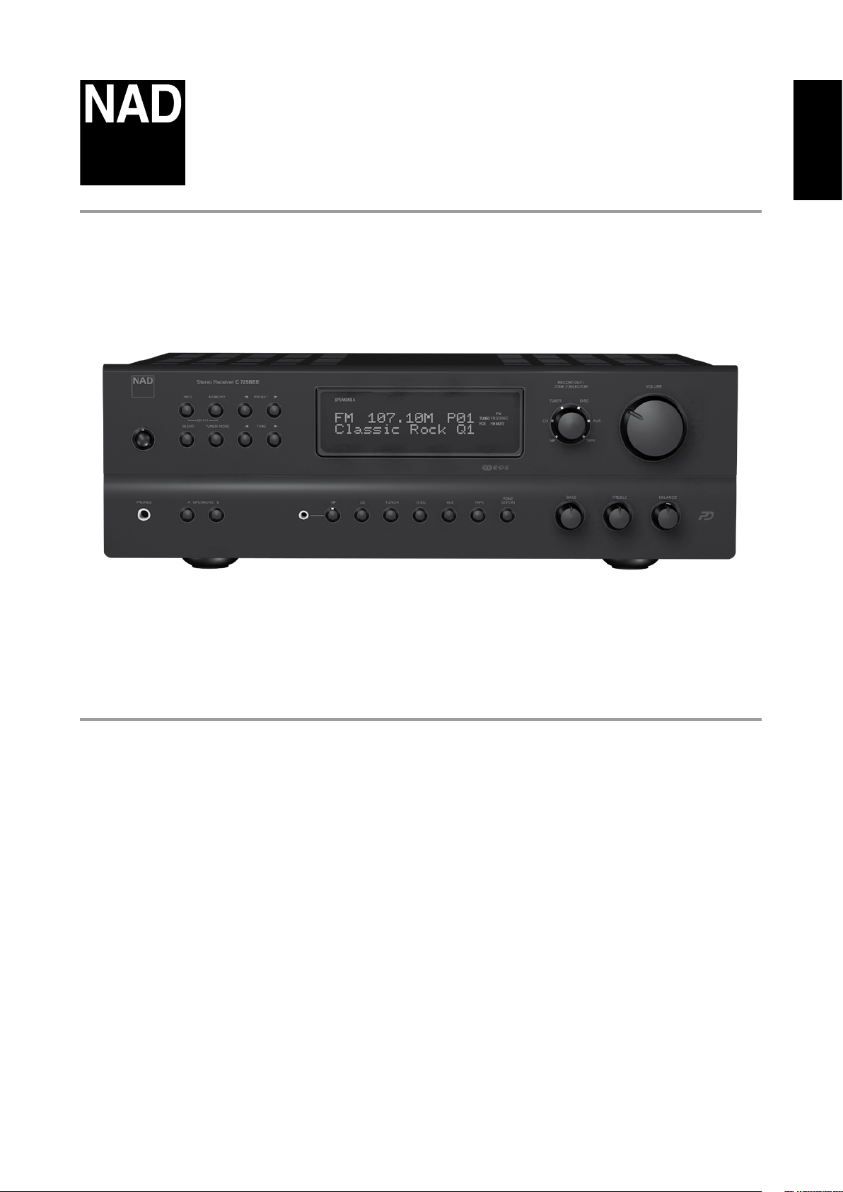
C 725BEE
Stereo Receiver
ENGLISHFRANÇAISESPAÑOLITALIANODEUTSCHNEDERLANDSSVENSKAРУССКИЙ
Owner’s Manual
IMPORTANT SAFETY INSTRUCTIONS
2
ENGLISH FRANÇAIS ESPAÑOL ITALIANO DEUTSCH NEDERLANDS SVENSKA РУССКИЙ
SAVE THESE INSTRUCTIONS FOR LATER USE.
FOLLOW ALL WARNINGS AND INSTRUCTIONS MARKED ON THE
AUDIO EQUIPMENT.
1 Read instructions - All the safety and operating instructions should be
read before the product is operated.
2 Retain instructions - The safety and operating instructions should be
retained for future reference.
3 Heed Warnings - All warnings on the product and in the operating
instructions should be adhered to.
4 Follow Instructions - All operating and use instructions should be
followed.
5 Cleaning - Unplug this product from the wall outlet before cleaning.
Do not use liquid cleaners or aerosol cleaners. Use a damp cloth for
cleaning.
6 Attachments - Do not use attachments not recommended by the
product manufacturer as they may cause hazards.
7 Water and Moisture - Do not use this product near water-for example,
near a bath tub, wash bowl, kitchen sink, or laundry tub; in a wet
basement; or near a swimming pool; and the like.
8 Accessories - Do not place this product on an unstable cart, stand,
tripod, bracket, or table. The product may fall, causing serious injury to
a child or adult, and serious damage to the product. Use only with a
cart, stand, tripod, bracket, or table recommended by the manufacturer,
or sold with the product. Any mounting of the product should follow
the manufacturer’s instructions, and should use a mounting accessory
recommended by the manufacturer.
9 A product and cart combination should be moved with
care. Quick stops, excessive force, and uneven surfaces may
cause the product and cart combination to overturn.
10 Ventilation - Slots and openings in the cabinet are provided for
ventilation and to ensure reliable operation of the product and to
protect it from overheating, and these openings must not be blocked
or covered. The openings should never be blocked by placing the
product on a bed, sofa, rug, or other similar surface. This product should
not be placed in a built-in installation such as a bookcase or rack unless
proper ventilation is provided or the manufacturer’s instructions have
been adhered to.
11 Power Sources - This product should be operated only from the type
of power source indicated on the marking label. If you are not sure of
the type of power supply to your home, consult your product dealer or
local power company.
The primary method of isolating the amplier from the mains supply
is to disconnect the mains plug. Ensure that the mains plug remains
accessible at all times. Unplug the AC power cord from the AC outlet if
the unit will not be used for several months or more.
12 Grounding or Polarization - This product may be equipped with a
polarized alternating-current line plug (a plug having one blade wider
than the other). This plug will t into the power outlet only one way.
This is a safety feature. If you are unable to insert the plug fully into the
outlet, try reversing the plug. If the plug should still fail to t, contact
your electrician to replace your obsolete outlet. Do not defeat the safety
purpose of the polarized plug.
13 Power - Cord Protection - Power-supply cords should be routed so that
they are not likely to be walked on or pinched by items placed upon or
against them, paying particular attention to cords at plugs, convenience
receptacles, and the point where they exit from the product.
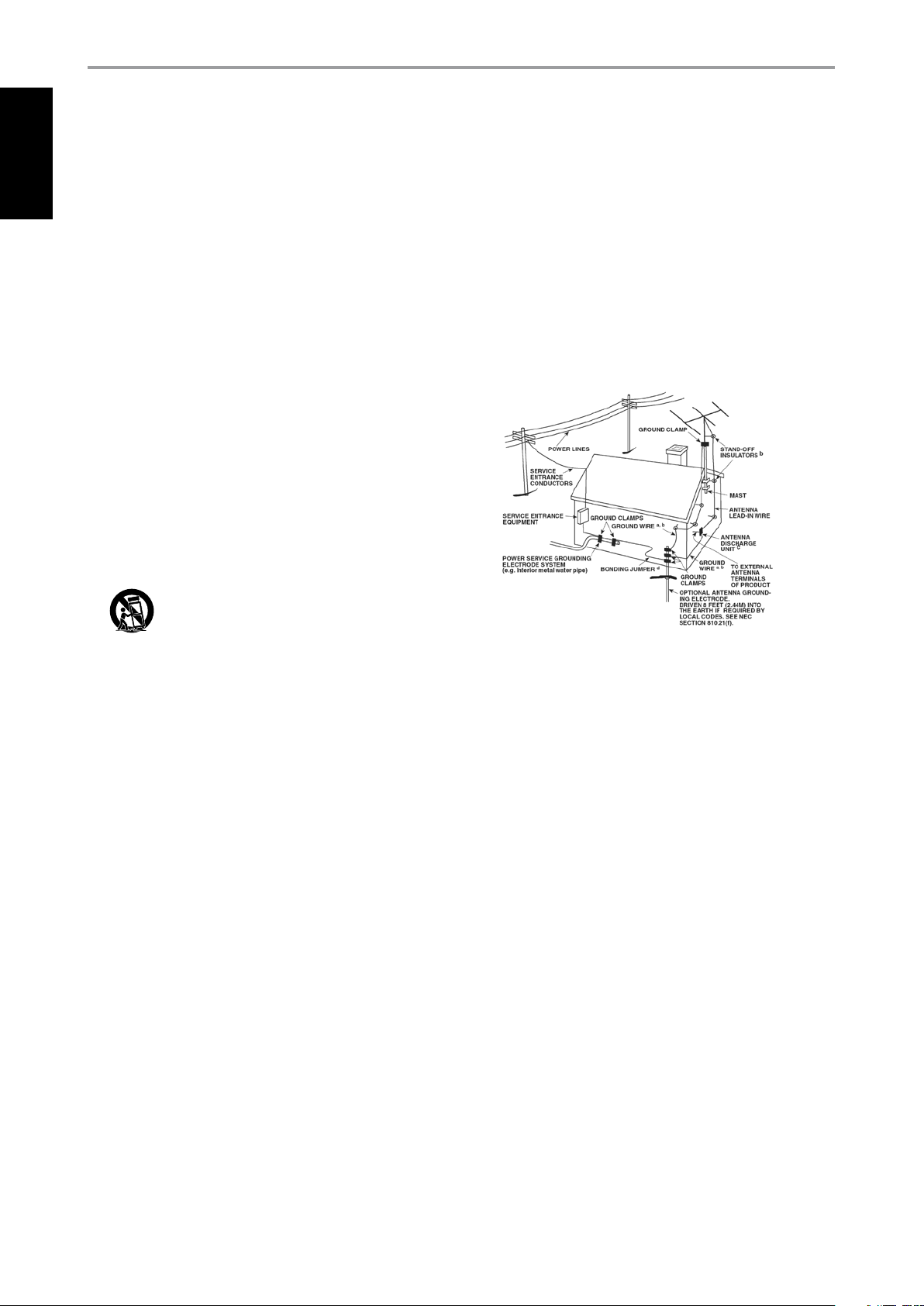
14 Outdoor Antenna Grounding - If an outside antenna or cable system
is connected to the product, be sure the antenna or cable system is
grounded so as to provide some protection against voltage surges
and built-up static charges. Article 810 of the National Electrical Code,
ANSI/NFPA 70, provides information with regard to proper grounding
of the mast and supporting structure, grounding of the lead-in wire
to an antenna discharge unit, size of grounding conductors, location
of antenna discharge unit, connection to grounding electrodes, and
requirements for the grounding electrode.
NOTE TO CATV SYSTEM INSTALLER
This reminder is provided to call the CATV system installer’s attention to Section
820-40 of the NEC which provides guidelines for proper grounding and, in
particular, species that the cable ground shall be connected to the grounding
system of the building, as close to the point of cable entry as practical.
15 Lightning - For added protection for this product during a lightning
storm, or when it is left unattended and unused for long periods of
time, unplug it from the wall outlet and disconnect the antenna or
cable system. This will prevent damage to the product due to lightning
and power-line surges.
16 Power Lines - An outside antenna system should not be located in the
vicinity of overhead power lines or other electric light or power circuits,
or where it can fall into such power lines or circuits. When installing an
outside antenna system, extreme care should be taken to keep from
touching such power lines or circuits as contact with them might be
fatal.
17 Overloading - Do not overload wall outlets, extension cords, or
integral convenience receptacles as this can result in a risk of re or
electric shock.
18 Object and Liquid Entry - Never push objects of any kind into this
product through openings as they may touch dangerous voltage points
or short-out parts that could result in a re or electric shock. Never spill
liquid of any kind on the product.
WARNING: THE APPARATUS SHOULD NOT BE EXPOSED TO
DRIPPING OR SPLASHING, AND OBJECTS FILLED WITH LIQUIDS,
SUCH AS VASES, SHOULD NOT BE PLACED ON THE APPARATUS.
AS WITH ANY ELECTRONIC PRODUCTS, USE CARE NOT TO SPILL
LIQUIDS INTO ANY PART OF THE SYSTEM. LIQUIDS CAN CAUSE A
FAILURE AND/OR A FIRE HAZARD.
IMPORTANT SAFETY INSTRUCTIONS
19 Damage Requiring Service - Unplug this product from the wall outlet
and refer servicing to qualied service personnel under the following
conditions:
a) When the power-supply cord or plug is damaged.
b) If liquid has been spilled, or objects have fallen into the product.
c) If the product has been exposed to rain or water.
d) If the product does not operate normally by following the operating
instructions. Adjust only those controls that are covered by the
operating instructions as an improper adjustment of other controls
may result in damage and will often require extensive work by a
qualied technician to restore the product to its normal operation.
e) If the product has been dropped or damaged in any way.
f) when the product exhibits a distinct change in performance-this
indicates a need for service.
20 Replacement Par ts - When replacement parts are required, be
sure the service technician has used replacement parts specified
by the manufacturer or have the same characteristics as the
original part. Unauthorized substitutions may result in fire, electric
shock, or other hazards.
21 Safety Check - Upon completion of any service or repairs to this
product, ask the service technician to perform safety checks to
determine that the product is in proper operating condition.
22 Wall or Ceiling Mounting - The product should be mounted to a wall
or ceiling only as recommended by the manufacturer.
23 Heat - The product should be situated away from heat sources such as
radiators, heat registers, stoves or other products (including ampliers)
that produce heat.
WARNING
TO REDUCE THE RISK OF FIRE OR ELECTRIC SHOCK, DO NOT EXPOSE THIS
PRODUCT TO RAIN OR MOISTURE.
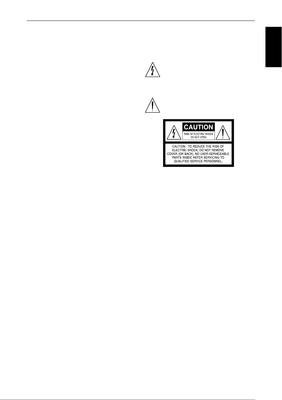
CAUTION
TO PREVENT ELECTRIC SHOCK, MATCH WIDE BLADE OF PLUG TO WIDE SLOT,
FULLY INSERT.
FCC WARNING
Changes or modications not expressly approved by the party responsible
for compliance could void the user’s authority to operate the equipment.
THE LIGHTNING FLASH WITH ARROWHEAD SYMBOL, WITHIN
AN EQUILATERAL TRIANGLE, IS INTENDED TO ALERT THE USER
TO THE PRESENCE OF UNINSULATED “DANGEROUS VOLTAGE”
WITHIN THE PRODUCT’S ENCLOSURE THAT MAYBE OF
SUFFICIENT MAGNITUDE TO CONSTITUTE A RISK OF ELECTRIC
SHOCK TO PERSONS.
THE EXCLAMATION POINT WITHIN AN EQUILATERAL TRIANGLE IS
INTENDED TO ALERT THE USER TO THE PRESENCE OF IMPORTANT
OPERATING AND MAINTENANCE (SERVICING) INSTRUCTIONS IN
THE LITERATURE ACCOMPANYING THE APPLIANCE.
The equipment draws its nominal non-operational power from the AC
outlet with its POWER switch in the STANDBY position.
The socket-outlet shall be installed near the apparatus and shall be easily
accessible.
CAUTION
Changes or modications to this equipment not expressly approved by
NAD Electronics for compliance could void the user’s authority to operate
this equipment.
CAUTION REGARDING PLACEMENT
To maintain proper ventilation, be sure to leave a space around the unit
(from the largest outer dimensions including projections) that is equal to or
greater than shown below.
Left and Right Panels: 10 cm
Rear Panel: 10 cm
Top Panel: 50 cm
ENGLISHFRANÇAISESPAÑOLITALIANODEUTSCHNEDERLANDSSVENSKAРУССКИЙ
3
IMPORTANT SAFETY INSTRUCTIONS
4
ENGLISH FRANÇAIS ESPAÑOL ITALIANO DEUTSCH NEDERLANDS SVENSKA РУССКИЙ
IMPORTANT INFORMATION FOR UK CUSTOMERS
DO NOT cut o the mains plug from this equipment. If the plug tted is not
suitable for the power points in your home or the cable is too short to reach
a power point, then obtain an appropriate safety approved extension lead
or consult your dealer. If, nonetheless, the mains plug is cut o, REMOVE
THE FUSE and dispose of the PLUG immediately, to avoid possible shock
hazard by inadvertent connection to the mains supply. If this product is
not provided with a mains plug, or one has to be tted, then follow the
instructions given below:
IMPORTANT
DO NOT make any connection to the larger terminal which is marked with
the letter ‘E’ or by the safety earth symbol or colored GREEN or GREEN AND
YELLOW.
The wires in the mains lead on this product are colored in accordance with
the following code:
BLUE – NEUTRAL
BROWN – LIVE
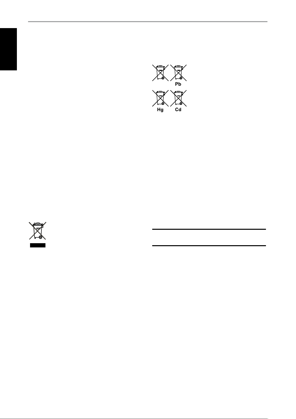
INFORMATION ABOUT COLLECTION AND DISPOSAL OF
WASTE BATTERIES DIRECTIVE 2006/66/EC OF THE EUROPEAN
PARLIAMENT AND THE COUNCIL OF EUROPEAN UNION FOR
EUROPEAN CUSTOMERS ONLY
Batteries bearing any of these symbols indicate
that they should be treated as “separate collection”
and not as municipal waste. It is encouraged that
necessary measures are implemented to maximize
the separate collection of waste batteries and
to minimize the disposal of batteries as mixed
municipal waste.
End-users are exhorted not to dispose waste
batteries as unsorted municipal waste. In order
to achieve a high level of recycling waste batteries, discard waste batteries
separately and properly through an accessible collection point in your
vicinity. For more information about collection and recycling of waste
batteries, please contact your local municipality, your waste disposal service
or the point of sale where you purchased the items.
As these colors may not correspond with the colored markings identifying
the terminals in your plug, proceed as follows:
The BLUE wire must be connected to the terminal marked with the
letter ‘N’ or colored BLACK.
The BROWN wire must be connected to the terminal marked with the
letter ‘L’ or colored RED.
When replacing the fuse, only a correctly rated and approved type should
be used, and be sure to re-t the fuse cover.
IF IN DOUBT CONSULT A COMPETENT ELECTRICIAN.
NOTES ON ENVIRONMENTAL PROTECTION
At the end of its useful life, this product must not be disposed
of with regular household waste but must be returned to a
collection point for the recycling of electrical and electronic
equipment. The symbol on the product, user’s manual and
packaging, point this out.
The materials can be reused in accordance with their markings. Through
re-use, recycling of raw materials or other forms of recycling of old
products, you are making an important contribution to the protection of
our environment. Your local administrative oce can advise you of the
responsible waste disposal point.
By ensuring compliance and conformance to proper disposal of waste
batteries, potential hazardous eects on human health is prevented and
the negative impact of batteries and waste batteries on the environment
is minimized, thus contributing to the protection, preservation and quality
improvement of the environment.
NOTE: THE C
CONNECT ONLY TO THE PRESCRIBED AC OUTLET, I.E., 120V 60HZ
OR 230V 50HZ.
RECORD YOUR MODEL NUMBER NOW, WHILE YOU CAN SEE IT
The model and serial number of your new C 725BEE are located on the
back of the cabinet. For your future convenience, we suggest that you
record these numbers here:
Model no: . . . . . . . . . . . . . . . . . . . . . . . . . . . . . . . . . . . . . .
Serial no.: . . . . . . . . . . . . . . . . . . . . . . . . . . . . . . . . . . . . . .
725BEE
IS NOT AN AUTO VOLTAGE RECEIVER.
NAD is a trademark of NAD Electronics International, a division of Lenbrook Industries Limited
Copyright 2008, NAD Electronics International, a division of Lenbrook Industries Limited

INTRODUCTION
TABLE OF CONTENTS
IMPORTANT SAFETY INSTRUCTIONS . . . . . . . . . . . . . . . . . . . . . . . . .2
INTRODUCTION
GETTING STARTED . . . . . . . . . . . . . . . . . . . . . . . . . . . . . . . . . . . . . . . . . . . . . . . 6
UNPACKING AND SETUP . . . . . . . . . . . . . . . . . . . . . . . . . . . . . . . . . . . . . . . . . . . . .6
CHOOSING A LOCATION . . . . . . . . . . . . . . . . . . . . . . . . . . . . . . . . . . . . . . . . . . . . .6
NOTES ON INSTALLATION . . . . . . . . . . . . . . . . . . . . . . . . . . . . . . . . . . . . . . . . . . . .6
ABOUT THE C 725BEE . . . . . . . . . . . . . . . . . . . . . . . . . . . . . . . . . . . . . . . . . . . . . . . . .6
IDENTIFICATION OF CONTROLS
FRONT PANEL . . . . . . . . . . . . . . . . . . . . . . . . . . . . . . . . . . . . . . . . . . . . . . . . . . . . 7
REAR PANEL . . . . . . . . . . . . . . . . . . . . . . . . . . . . . . . . . . . . . . . . . . . . . . . . . . . . . 9
REMOTE CONTROL . . . . . . . . . . . . . . . . . . . . . . . . . . . . . . . . . . . . . . . . . . . . .11
USING THE SR 8 REMOTE CONTROL . . . . . . . . . . . . . . . . . . . . . . . . . . . . . . . . 11
USING THE ZR 5 REMOTE CONTROL . . . . . . . . . . . . . . . . . . . . . . . . . . . . . . . . 13
OPERATION
LISTENING TO AM/FM RADIO . . . . . . . . . . . . . . . . . . . . . . . . . . . . . . . . . . . .14
ABOUT ANTENNAS . . . . . . . . . . . . . . . . . . . . . . . . . . . . . . . . . . . . . . . . . . . . . . . . . 14
TUNING STATIONS . . . . . . . . . . . . . . . . . . . . . . . . . . . . . . . . . . . . . . . . . . . . . . . . . . 15
SET TING RADIO PRESETS AM/FM/DAB . . . . . . . . . . . . . . . . . . . . . . . . . . . . 15
CHOOSING TUNER MODE . . . . . . . . . . . . . . . . . . . . . . . . . . . . . . . . . . . . . . . . . . 16
ABOUT USER NAMES . . . . . . . . . . . . . . . . . . . . . . . . . . . . . . . . . . . . . . . . . . . . . . . 16
ABOUT RDS . . . . . . . . . . . . . . . . . . . . . . . . . . . . . . . . . . . . . . . . . . . . . . . . . . . . . . . . 16
THANK YOU FOR CHOOSING NAD.
The C 725BEE Stereo Receiver is a technologically advanced and highly
capable product — yet we have invested great eort in making it simple
and easy to use. We have been careful to ensure that the C 725BEE is as
musically transparent and spatially accurate as possible, incorporating
much of what we’ve learned from a quarter-century’s experience designing
audio, video and home-theater components.
As with all our products, NAD’s “Music First” design philosophy guided the
C 725BEE’s design in such a way that it can condently promise you stateof-the-art audiophile-quality music listening for years to come.
LISTENING TO DAB RADIO . . . . . . . . . . . . . . . . . . . . . . . . . . . . . . . . . . . . . . . 17
ABOUT DAB RADIO 230V VERSION ONLY . . . . . . . . . . . . . . . . . . . . . . . . . 17
CONNECTING THE DAB MODULE . . . . . . . . . . . . . . . . . . . . . . . . . . . . . . . . . . 17
DAB OPERATION . . . . . . . . . . . . . . . . . . . . . . . . . . . . . . . . . . . . . . . . . . . . . . . . . . . 17
SERVICE LIST . . . . . . . . . . . . . . . . . . . . . . . . . . . . . . . . . . . . . . . . . . . . . . . . . . . . . . . 17
DAB TUNER MODE . . . . . . . . . . . . . . . . . . . . . . . . . . . . . . . . . . . . . . . . . . . . . . . . . 17
STATION ORDER . . . . . . . . . . . . . . . . . . . . . . . . . . . . . . . . . . . . . . . . . . . . . . . . . . . . 18
DRC . . . . . . . . . . . . . . . . . . . . . . . . . . . . . . . . . . . . . . . . . . . . . . . . . . . . . . . . . . . . . . . . 18
MANUAL SCAN . . . . . . . . . . . . . . . . . . . . . . . . . . . . . . . . . . . . . . . . . . . . . . . . . . . . . 18
PRUNE LIST . . . . . . . . . . . . . . . . . . . . . . . . . . . . . . . . . . . . . . . . . . . . . . . . . . . . . . . . . 18
RESET . . . . . . . . . . . . . . . . . . . . . . . . . . . . . . . . . . . . . . . . . . . . . . . . . . . . . . . . . . . . . . 18
INFORMATION SETTINGS . . . . . . . . . . . . . . . . . . . . . . . . . . . . . . . . . . . . . . . . . . . 19
LISTENING TO YOUR iPod PLAYER . . . . . . . . . . . . . . . . . . . . . . . . . . . . . . . .20
CONNECTING THE OPTIONAL “NAD IPD 1 DOCK WITH
iPod” AND iPod PLAYER TO THE C 725BEE . . . . . . . . . . . . . . . . . . . . . . . . . . . 20
iPod MENU OPTIONS . . . . . . . . . . . . . . . . . . . . . . . . . . . . . . . . . . . . . . . . . . . . . . . 20
CONTROL FEATURES . . . . . . . . . . . . . . . . . . . . . . . . . . . . . . . . . . . . . . . . . . . . . . . 21
REFERENCE
TROUBLESHOOTING . . . . . . . . . . . . . . . . . . . . . . . . . . . . . . . . . . . . . . . . . . . .22
SPECIFICATIONS . . . . . . . . . . . . . . . . . . . . . . . . . . . . . . . . . . . . . . . . . . . . . . . . 23
We encourage you to take a few minutes now to read right through this
manual. Investing a little time here at the outset might save you a good
deal of time later and is by far the best way to ensure that you make the
most of your investment in the C 725BEE.
One more thing: We urge you to register your C 725BEE ownership on the
NAD Worldwide Web site:
http://NADelectronics.com/warranty
For warranty information contact your local distributor.
ENGLISHFRANÇAISESPAÑOLITALIANODEUTSCHNEDERLANDSSVENSKAРУССКИЙ
5

INTRODUCTION
6
ENGLISH FRANÇAIS ESPAÑOL ITALIANO DEUTSCH NEDERLANDS SVENSKA РУССКИЙ
GETTING STARTED
UNPACKING AND SETUP
WHAT’S IN THE BOX
Packed with your C 725BEE you will nd:
• The SR 8 remote control with 2 (two) AAA batteries
• ZR 5 zone remote control with 3V CR2025 battery
• This owner’s manual
SAVE THE PACKAGING
Please save the box and all of the packaging in which your C 725BEE
arrived. Should you move or otherwise need to transport your C 725BEE,
this is by far the safest container in which to do so. We’ve seen too many
otherwise perfect components damaged in transit for lack of a proper
shipping carton, so please: Save that box!
CHOOSING A LOCATION
Choose a location that is well ventilated (with at least several inches to
both sides and behind), and that will provide a clear line of sight, within
23 feet/7 meters, between the C 725BEE’s front panel and your primary
listening/viewing position - this will ensure reliable infrared remote control
communications. The C 725BEE generates a modest amount of heat, but
nothing that should trouble adjacent components.
NOTES ON INSTALLATION
Your C 725BEE should be placed on a rm, level surface. Avoid placing the
unit in direct sunlight or near sources of heat and damp. Allow adequate
ventilation. Do not place the unit on a soft surface like a carpet. Do not
place it in an enclosed position such a bookcase or cabinet that may
impede the air-ow through the ventilation slots.
ABOUT THE C 725BEE
Though the C 725BEE is among the most technically sophisticated Stereo
Receivers, we worked hard to make it one of the most musically transparent
components available as well. This is what we mean by NAD’s “Music First”
design philosophy. Here are just a few examples
• The C 725BEE uses NAD’s proprietary Power Drive™ amplier technology
for all channels to preserve accurate, linear reproduction regardless of the
loudspeaker. This uniquely ecient power-supply topology provides the
real-world benets of high dynamic power that remains uncompromised
by low-impedance speakers. By adding a second high-voltage rail to our
well regulated high-current power supply, we get an “overdrive” that can
nearly double the continuous power on a short term dynamic power basis.
The result is dynamic, detailed,”un-receiver-like” sound in stereo mode.
NAD’s exclusive Soft Clipping™ circuitry further enhances sound quality and
dynamic potential.
• High-performance components used throughout the receiver’s analog
audio circuits to maximize quality from all sources.
• Preamp output and main-amp input jacks make potential expansion as
exible as possible.
• A Second set of Speaker terminals (Speakers B) for remote listening.
• An RS-232 port for advanced zone control and software update through
a Windows® compatible PC.
• Gold-surfaced connectors are employed throughout to ensure
maximum signal integrity.
Make sure the unit is switched o before making any connections.
The RCA sockets on your C 725BEE are color coded for convenience. Red
and white are Right and Left audio respectively.
Use high quality leads and sockets for optimum performance and reliability.
Ensure that leads and sockets are not damaged in any way and all sockets
are rmly pushed home.
For best performance, use quality speaker leads of 16 gauge (1.5mm)
thickness or more.
If you intend not to use the C 725BEE for long periods of time, switch OFF
the rear panel POWER switch.
Should water get into your C 725BEE, shut o the power to the unit and
disconnect the plug from the AC wall outlet. Have the unit inspected by a
qualied service technician before attempting to use it again.
DO NOT REMOVE THE COVER; THERE ARE NO USERSERVICEABLE
PARTS INSIDE.
Use a dry soft cloth to clean the unit. If necessary, lightly dampen the cloth
with soapy water. Do not use solutions containing benzol or other volatile
agents.
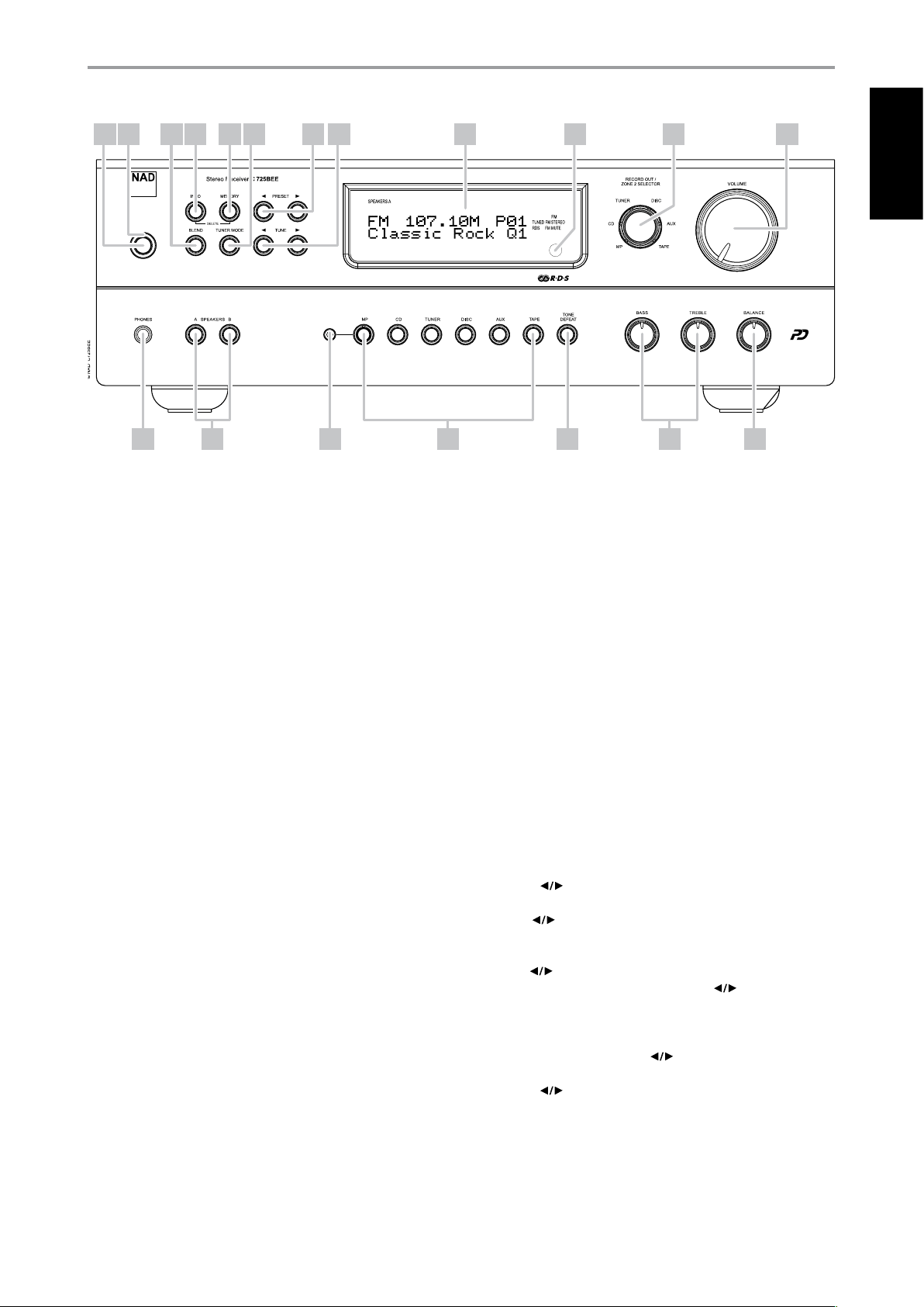
IDENTIFICATION OF CONTROLS
FRONT PANEL
1 9
2 3 4 5 6 7 8 10 11 12
ENGLISHFRANÇAISESPAÑOLITALIANODEUTSCHNEDERLANDSSVENSKAРУССКИЙ
19181713 14 15 16
1 STANDBY: With the rear panel POWER switch set to ON position, press this
button to switch ON the C 725BEE from standby mode. The Standby LED
indicator will turn from amber to blue and illuminate the VFD. Pressing the
[Standby] button again turns the unit back to standby mode.
The C 725BEE can also be switched ON from standby mode by pressing
any of the front panel buttons.
2 STANDBY LED: This indicator will light up amber when the C 725BEE
is in standby state. When the C 725BEE is at ON state, this indicator will
illuminate blue. When infrared command from the SR 8 is received, this
indicator will also ash momentarily.
In cases of serious abuse of the C 725BEE, such as excessively low
loudspeaker impedance and short circuit, the C 725BEE will engage its
Protection circuitry, indicated by the Standby LED turning from blue to
red and the sound being muted. At Protect mode, the Standby LED in
red color will ash and “Protect!” shown ashing also in the VFD. In the
case of overheating, the Standby LED in red color will ash and the VFD
turned o.
In such a case, turn the C 725BEE o by the rear panel POWER button,
wait for it to cool down and/or check the speaker connections,
making sure the overall loudspeaker impedance doesn’t go below 4
ohms. Once the cause for the protection circuitry to engage has been
removed, switch ON the rear POWER button and the Standby Button to
resume normal operation.
3 BLEND: The NAD BLEND feature will allow you to reduce the amount of
noise and hiss but still retain some level of stereo separation, instead of
mono. The BLEND button toggles between engaging and disengaging
the BLEND feature. When engaged, “Blend On” is shown at the lower line
of the VFD; “Blend O” when not active. The “Blend On” or “Blend O”
status can be stored for individual presets.
4 INFO: Toggle this button for the lower line of the VFD to show various
settings, conditions and other information relevant to the currently
tuned station or broadcast.
5 MEMORY: Press this button to store tuned AM, FM and digital radio
stations to the C 725BEE’s 40 preset-memory locations. One can store a
mix of any AM, FM and DAB broadcasts to the 40 available presets.
In combination with [INFO] button, [MEMORY] button is also used in
deleting stored presets. Press and hold [INFO] button and then press
[MEMORY] – current stored preset setting will be erased. Refer also to
the item about SETTING RADIO PRESETS at the LISTENING TO AM/FM
RADIO section of the OPERATION page.
6 TUNER MODE: In FM mode, toggle this button to switch between
“FM Mute On” (stereo) and “FM Mute O” (mono). Select “FM Mute O”
for stations that have too much interference or are too weak. When
engaged, “FM Mute On” is shown at the lower line of the VFD; “FM Mute
O” when not active. The “FM Mute On” or “FM Mute O” status can be
stored for individual presets. Refer also to the item about CHOOSING
TUNER MODE at the LISTENING TO AM/FM RADIO section of the
OPERATION page.
In DAB mode, pressing this button will activate Dynamic Range Control
(DRC), Station Order or other applicable DAB menu options. Refer also
to the item about DAB TUNER MODE at the LISTENING TO DAB RADIO
section of the OPERATION page.
7 PRESET [ ] : Press to step up or down between stored radio
presets; 40 presets are available. Note that this function “wraps”: Pressing
[PRESET ] will step from Preset 1 to Preset 40 or vice versa. “Unused”
presets are skipped over.
8 TUNE [ ] : Toggle either button to step up or down between
AM or FM frequencies. Press and release [TUNE ] to search up or
down - the C 725BEE will stop at the next suciently strong signal it
encounters. Note that this function “wraps” – that is, it will continue to
search from one end of the AM or FM band to the other until it stops
at a strong signal. Pressing [TUNE ] during the search process will
stop the search. Refer also to “OPERATION – LISTENING TO DAB RADIO”
for [TUNE ] usage in DAB operation.
9 VACUUM FLUORESCENT DISPLAY (VFD): Provide visual information
about the unit’s important modes, settings, functions, status of the
current source and other indicators. When in tuner mode, it displays
information about the current station or broadcast as supplied by the
service provider among other tuner settings.
7

IDENTIFICATION OF CONTROLS
8
ENGLISH FRANÇAIS ESPAÑOL ITALIANO DEUTSCH NEDERLANDS SVENSKA РУССКИЙ
FRONT PANEL
10 REMOTE SENSOR: Point the SR 8 remote control at the remote
sensor and press the buttons. Do not expose the remote sensor of the
C 725BEE to a strong light source such as direct sunlight or illumination.
If you do so, you may not be able to operate the C 725BEE with the
remote control.
14 A SPEAKERS B: The SPEAKERS A and B buttons engage or disengage
the speakers connected respectively to the SPEAKERS A and SPEAKERS
B terminals on the rear panel. Press “A” to switch ON or OFF the speakers
connected to the SPEAKERS A terminals. Press “B” to switch ON or OFF
the speakers connected to the SPEAKERS B terminals.
Distance: About 23ft (7m) from the front of the remote sensor.
Angle: About 30o in each direction of the front of the remote sensor.
11 RECORD OUT/ZONE 2 SELECTOR: This knob doubles as both a record
and zone source selector. Rotate knob and select the Source you would
like to be directed out to REC OUT/ZONE 2 output port in the rear panel.
The directed Source signal at the REC OUT/ZONE 2 output port could
be used for making audio recordings or as an audio input to a separate
zone in your home.
ABOUT ZONE FEATURE
The Zone feature allows one to simultaneously listen to another active
Source of the C 725BEE that is dierent from the currently selected Source.
For example, while the C 725BEE is at CD mode, you can set the RECORD
OUT/ZONE 2 SELECTOR knob to “TUNER” and the active tuned station’s
audio will be directed to REC OUT/ZONE 2 output port in the rear panel.
You can then feed the REC OUT/ZONE 2 jack to another amplier or receiver
that is located maybe in another area of your home or building. With your
separate amplier or receiver selecting the fed signal and with speakers
connected, you can then enjoy listening to the tuned station. You can
vary the level of the tuned station by adjusting the Volume control of the
separate amplier, receiver or ZR 5’s [ VOL ] buttons. Refer also to the
item USING THE ZR 5 REMOTE CONTROL at the REMOTE CONTROL section
of the IDENTIFICATION OF CONTROLS page.
12 VOLUME: The VOLUME control adjusts the overall loudness of the signals
being fed to the loudspeakers or headphones. Turn clockwise to increase
the volume setting; counter clockwise to lower it. The VOLUME control does
not aect recordings made using the REC OUT/ZONE 2 output but will
aect the signal going to the Pre-amp output (PRE OUT).
NOTE
If the Volume level is adjusted using the SR 8’s [VOL ] buttons, the
lower line of the VFD will show “Volume Up” when level is increased or
“Volume Down” if level is decreased.
13 PHONES: A 1/4” stereo jack socket is supplied for headphone listening
and will work with conventional headphones of any impedance. The
headphone socket will work in parallel to the selected speakers. To
listen to headphones only, de-select Speakers A and/or B. The volume,
tone and balance controls are operative for headphone listening. Use
a suitable adapter to connect headphones with other types of sockets,
such as 3.5mm “personal stereo” jack plugs.
NOTE
Make certain that the volume control is turned to minimum (fully
counter-clockwise) before connecting or disconnecting headphones.
Listening at high levels can damage your hearing.
15 MP SOCKET: Using a 3.5mm stereo plug, connect into this socket the
audio output of a Media Player. The LED on the MP input button will
illuminate when an external Media Player is connected to this socket.
16 INPUT SELECTORS: These buttons select the active input to the NAD
C 725BEE and the signal sent to the loudspeakers, headphones and the
PRE OUT socket. The buttons on the remote control handset duplicate
these buttons. The selected input will be displayed in the VFD.
MP (MEDIA PLAYER): Selects a line-level source connected to the MP
sockets as the active input. If the DATA port of the optional NAD IPD 1
Dock with iPod (NAD IPD 1) is connected to the corresponding DATA
PORT in the rear panel, your iPod player docked and with the NAD IPD
1’s AUDIO OUT also connected to the rear panel MP input, the lower
line of the VFD will show “iPod Connected”. Refer also to LISTENING TO
YOUR iPod PLAYER under the OPERATION main heading.
If an external Media Player is connected to the front MP socket (using
a 3.5mm stereo plug) while listening to a MP line-level source, the
external Media Player will be directly selected with the MP line-level
source immediately disconnected. It is recommended to mute the
volume or switch to a dierent input before plugging/unplugging the
external Media Player cable.
CD: Selects the CD (or other line-level source) connected to the CD
sockets as the active input.
TUNER: Toggle to select AM, FM or DAB (230V version only) tuner band.
DISC: Selects a line-level source connected to the DISC sockets as the
active input.
AUX: Selects a line-level source connected to the AUX sockets as the
active input.
TAPE: Selects the Tape (or other line-level source) connected to the
TAPE sockets as the active input.
17 TONE DEFEAT: Tone Controls are enabled or disabled by pressing this
button. The lower line of the VFD will show “Tone Defeat” when the tone
controls are bypassed or “ Tone Active” if the tone controls are enabled.
18 TONE CONTROLS: The NAD C 725BEE is tted with BASS and TREBLE
tone controls to adjust the tonal balance of your system. The 12 o’clock
position is “at” with no boost or cut, and an indent indicates this
position. Rotate the control clockwise to increase the amount of Bass or
Treble. Rotate the control counterclockwise to decrease the amount of
Bass or Treble. The Tone controls do not aect recordings made using
the REC OUT/ZONE 2 output but will aect the signal going to the Preamp output (PRE OUT).
19 BALANCE: The BALANCE control adjusts the relative levels of the left
and right speakers. The 12 o’clock position provides equal level to the
left and right channels. A detent indicates this position. Rotating the
control clockwise moves the balance towards the right. Rotating the
control counterclockwise moves the balance to the left. The BALANCE
control does not aect recordings made using the REC OUT/ZONE
2 output but will aect the signal going to the Pre-amp output (PRE
OUT).
 Loading...