

Page 1

NAD
SERVICE MANUAL
C 355BEE
STEREO
C 355BEE
STEREO
AMPLIFIER
AMPLIFIER
Page 2

TABLE OF CONTENTS
DESCRIPTION P A G E
SERVICE CAUTION…………………………………………………………..3-4
REAR PANEL/FRONT PANEL VIEW………………………………………..5
SPECIFICATIONS…………………………………………………………6-7
WIRING DIAGRAM………………………………………………………………8
BLOCK DIAGRAM……………………………………………………. …….9-13
ALIGNMENT PROCEDURE........................................................14
SCHEMATICS……………………………………………………………....15-18
PCB LAYOUT……………………………………………………………….19-22
TROUBLE SHOOTING GUIDE…………………......................................23
ELECTRICAL PARTS LIST…………………………………………….24-33
EXPLODED VIEW……………………………………………………………..34
EXPLODED VIEW PARTS LIST……………………………………………....35
Page 3
PRODUCT SAFETY SERVICING GUIDELINES
CAUTION : DO NOT ATTEMPT TO MODIFY THIS PRODUCT IN
ANY WAY. NEVER PERFORM CUSTOMIZED INSTALLATIONS
WITHOUT MANUFACTURER’S APPROVAL. UNAUTHORIZED
MODIFICATIONS WILL NOT ONLY VOID THE WARRANTY, BUT
MAY LEAD TO YOUR BEING LIABLE FOR ANY RESULTING
PROPERTY DAMAGE OR USER INJURY.
SERVICE WORK SHOULD BE PERFORMED ONLY AFTER YOU
ARE THOROUGHLY FAMILIAR WITH ALL OF THE FOLLOWING
SAFETY CHECKS AND SERVICING GUIDELINES. TO DO
OTHERWISE, INCREASES THE RISK OF POTENTIAL HAZARDS
AND INJURY TO THE USER.
WHILE SERVICING, USE AN ISOLATION TRANSFORMER FOR
PROTECTION FROM AC LINE SHOCK.
SAFETY CHECKS
AFTER THE ORIGINAL SERVICE PROBLEM HAS BEEN
CORRECTED. A CHECK SHOULD BE MADE OF THE
FOLLOWING.
SUBJECT : FIRE & SHOCK HAZARD
1. BE SURE THAT ALL COMPONENTS ARE POSITIONED IN
SUCH A WAY AS TO AVOID POSSIBILITY OF ADJACENT
COMPONENT SHORTS. THIS IS ESPECIALLY IMPORTANT
ON THOSE MODULES WHICH ARE TRANSPORTED TO AND
FROM THE REPAIR SHOP.
2. NEVER RELEASE A REPAIR UNLESS ALL PROTECTIVE
DEVICES SUCH AS INSULATORS, BARRIERS, COVERS,
SHIELDS, STRAIN RELIEFS, POWER SUPPLY CORDS, AND
OTHER HARDWARE HAVE BEEN REINSTALLED PER
ORIGINAL DESIGN. BE SURE THAT THE SAFETY PURPOSE
OF THE POLARIZED LINE PLUG HAS NOT BEEN DEFEATED.
3. SOLDERING MUST BE INSPECTED TO DISCOVER POSSIBLE
COLD SOLDER JOINTS, SOLDER SPLASHES OR SHARP
SOLDER POINTS. BE CERTAIN TO REMOVE ALL LOOSE
FOREIGN PARTICLES.
4. CHECK FOR PHYSICAL EVIDENCE OF DAMAGE OR
DETERIORATION TO PARTS AND COMPONENTS. FOR
FRAYED LEADS, DAMAGED INSULATION (INCLUDING AC
CORD). AND REPLACE IF NECESSARY FOLLOW ORIGINAL
LAYOUT, LEAD LENGTH AND DRESS.
5. NO LEAD OR COMPONENT SHOULD TOUCH A RECEIVING
TUBE OR A RESISTOR RATED AT 1 WATT OR MORE. LEAD
TENSION AROUND PROTRUDING METAL SURFACES MUST
BE AVOIDED.
6. ALL CRITICAL COMPONENTS SUCH AS FUSES,
FLAMEPROOF RESISTORS, CAPACITORS, ETC. MUST BE
REPLACED WITH EXACT FACTORY TYPES, DO NOT USE
REPLACEMENT COMPONENTS OTHER THAN THOSE
SPECIFIED OR MAKE UNRECOMMENDED CIRCUIT
MODIFICATIONS.
7. AFTER RE-ASSEMBLY OF THE SET ALWAYS PERFORM AN
AC LEAKAGE TEST ON ALL EXPOSED METALLIC PARTS OF
THE CABINET, (THE CHANNEL SELECTOR KNOB, ANTENNA
TERMINALS. HANDLE AND SCREWS) TO BE SURE THE SET
IS SAFET TO OPERATE WITHOUT DANGER OF ELECTRICAL
SHOCK. DO NOT USE A LINE ISOLATION TRANSFORMER
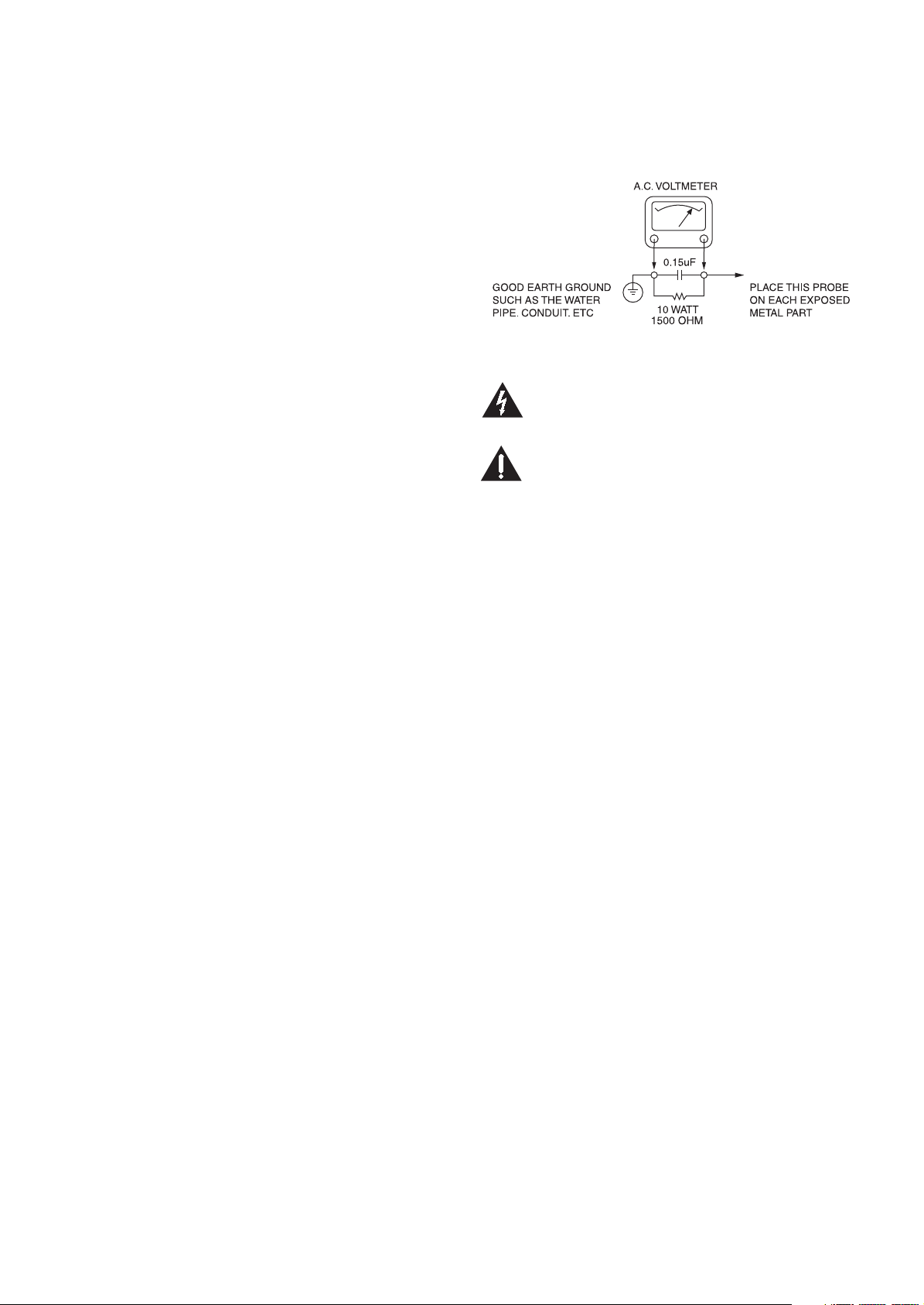
DURING THIS TEST USE AN AC VOLTMETER, HAVING 5000
OHMS PER VOLT OR MORE SENSITIVITY, IN THE
FOLLOWING MANNER; CONNECT A 1500 OHM 10 WATT
RESISTOR, PARALLELED BY A .15 MFD, 150V AC TYPE
CAPACITOR BETWEEN A KNOWN GOOD EARTH GROUND
(WATER PIPE, CONDUIT, ETC.) AND THE EXPOSED
METALLIC PARTS, ONE AT A TIME.
MEASURE THE AC VOLTAGE ACROSS THE COMBINATION
OF 1500 OHM RESISTOR AND .15 MFD CAPACITOR.
REVERSE THE AC PLUG AND REPEAT AC VOLTAGE
MEASUREMENTS FOR EACH EXPOSED METALLIC PART.
VOLTAGE MEASURE MUST NOT EXCEED 75 VOLTS R.M.S.
THIS CORRESPONDS TO 0.5 MILLIAMP AC ANY VALUE
EXCEEDING THIS LIMIT CONSTITUTES A POTENTIAL
SHOCK HAZARD AND MUST BE CORRECTED IMMEDIATELY.
SUBJECT : GRAPHIC SYMBOLS
THE LIGHTNING FLASH WITH ARROWHEAD SYMBOL, WITHIN AN
EQUILATERAL TRIANGLE, IS INTENDED TO ALERT THE USER TO THE
PRESENCE OF UNINSULATED “DANGEROUS VOLTAGE” WITHIN THE
PRODUCT’S ENCLOSURE THAT MAY BE OF SUFFICIENT MAGNITUDE TO
CONSTITUTE A RISK OF ELECTRIC SHOCK.
THE EXCLAMATION POINT WITHIN AN EQUILATERAL TRIANGLE IS
INTENDED TO ALERT THE USER TO THE PRESENCE OF IMPORTANT
OPERATING AND MAINTENANCE (SERVICING) INSTRUCTIONS IN THE
LITERATURE ACCOMPANYING THE APPLIANCE.
SUBJECT : TIPS ON PROPER INSTALLATION
1. NEVER INSTALL ANY PRODUCT IN A CLOSED-IN RECESS,
CUBBYHOLE OR CLOSELY FITTING SHELF SPACE. OVER
OR CLOSE TO HEAT DUCT, OR IN THE PATH OF HEATED
AIR FLOW.
2. AVOID CONDITIONS OF HIGH HUMIDITY SUCH AS:
OUTDOOR PATIO INSTALLATIONS WHERE DEW IS A
FACTOR, NEAR STEAM RADIATORS WHERE STEAM
LEAKAGE IS A FACTOR, ETC.
3. AVOID PLACEMENT WHERE DRAPERIES MAY OBSTRUCT
REAR VENTING. THE CUSTOMER SHOULD ALSO AVOID THE
USE OF DECORATIVE SCARVES OR OTHER COVERINGS
WHICH MIGHT OBSTRUCT VENTILATION.
4. WALL AND SHELF MOUNTED INSTALLATIONS USING A
COMMERCAL MOUNTING KIT MUST FOLLOW THE FACTORY
APPROVED MOUNTING INSTRUCTIONS A PRODUCT
MOUNTED TO A SHELF OR PLATFORM MUST RETAIN ITS
ORIGINAL FEET (OR THE EQUIVALENT THICKNESS IN
SPACERS) TO PROVIDE ADEQUATE AIR FLOW ACROSS
THE BOTTOM, BOLTS OR SCREWS USED FOR FASTENERS
MUST NOT TOUCH ANY PARTS OR WIRING. PERFORM
LEAKAGE TEST ON CUSTOMIZED INSTALLATIONS.
5. CAUTION CUSTOMERS AGAINST THE MOUNTING OF A
PRODUCT ON SLOPING SHELF OR A TILTED POSITION,
UNLESS THE PRODUCT IS PROPERLY SECURED.
6. A PRODUCT ON A ROLL-ABOUT CART SHOULD BE STABLE
ON ITS MOUNTING TO THE CART. CAUTION THE
CUSTOMER ON THE HAZARDS OF TRYING TO ROLL A CART
WITH SMALL CASTERS ACROSS THRESHOLDS OR DEEP
PILE CARPETS.
7. CAUTION CUSTOMERS AGAINST THE USE OF A CART OR
STAND WHICH HAS NOT BEEN LISTED BY UNDERWRITERS
LABORATORIES, INC. FOR USE WITH THEIR SPECIFIC
MODEL OF TELEVISION RECEIVER OR GENERICALLY
APPROVED FOR USE WITH T.V.’S OF THE SAME OR
LARGER SCREEN SIZE.
8. CAUTION CUSTOMERS AGAINST THE USE OF EXTENSION
CORDS, EXPLAIN THAT A FOREST OF EXTENSIONS
SPROUTING FROM A SINGLE OUTLET CAN LEAD TO
DISASTROUS CONSEQUENCES TO HOME AND FAMILY.
3
Page 4

SERVICING PRECAUTIONS
CAUTION : Before servicing the A/V Receiver covered by this
service data and its supplements and addends, read and follow the
SAFETY PRECAUTIONS. NOTE : if unforeseen circumstances
create conflict between the following servicing precautions and any
of the safety precautions in this publication, always follow the safety
precautions.
Remember Safety First:
General Servicing Precautions
1. Always unplug the A/V Receiver AC power cord from the AC
power source before:
(1) Removing or reinstalling any component, circuit board,
module, or any other assembly.
(2) Disconnecting or reconnecting any internal electrical plug or
other electrical connection.
(3) Connecting a test substitute in parallel with an electrolytic
capacitor.
Caution : A wrong part substitution or incorrect polarity installation
of electrolytic capacitors may result in an explosion hazard.
2. Do not spray chemicals on or near this A/V Receiver or any of its
assemblies.
3. Unless specified otherwise in this service data, clean electrical
contacts by applying an appropriate contact cleaning solution to
the contacts with a pipe cleaner, cottontipped swab, or
comparable soft applicator.
Unless specified otherwise in this service data, lubrication of
contacts is not required.
4. Do not defeat any plug/socket B+ voltage interlocks with which
instruments covered by this service manual might be equipped.
5. Do not apply AC power to this A/V Receiver and/or any of its
electrical assemblies unless all solid-state device heat sinks are
correctly installed.
6. Always connect test instrument ground lead to the appropriate
ground before connecting the test instrument positive lead. Always
remove the test instrument ground lead last.
Insulation Checking Procedure
Disconnect the attachment plug from the AC outlet and turn the
power on. Connect an insulation resistance meter(500V) to the
blades of the attachment plug. The insulation resistance between
each blade of the attachment plug and accessible conductive parts
(Note 1) should be more than 1M-ohm.
Note 1 : Accessible Conductive Parts including Metal panels, Input
terminals, Earphone jacks, etc.
Electrostatically Sensitive (ES) Devices
Some semiconductor (solid state) devices can be damaged easily by
static electricity. Such components commonly are called
Electrostatically Sensitive (ES) Devices. Examples of typical Es
devices are integrated circuits and some field effect transistors and
semiconductor chip components.
The following techniques should be used to help reduce the
incidence of component damage caused by static electricity.
1. Immediately before handling any semiconductor component or
semiconductor-equipped assembly, drain off any electrostatic
charge on your body by touching a known earth ground.
Alternatively, obtain and wear a commercially available
discharging wrist strap device, which should be removed for
potential shock reasons prior to applying power to the unit under
test.
2. After removing an electrical assembly equipped with ES devices,
place the assembly on a conductive surface such as aluminum
foil, to prevent electrostatic charge buildup or exposure of the
assembly.
3. Use only a grounded-tip soldering iron to solder or unsolder ES
devices.
4. Use only an antistatic solder removal device. Some solder
removal devices not classified a “anti-static” can generate
electrical charges sufficient to damage ES devices.
5. Do not use freonpropelled chemicals. These can generate
electrical charge sufficient to damage ES devices.
6. Do not remove a replacement ES device from its protective
package until immediately before you are ready to install it. (Most
replacement ES devices are packaged with leads electrically
shorted together by conductive foam, aluminum foil, or
comparable conductive material).
7. lmmediately before removing the protective material from the
leads of a replacement ES device, touch the protective material to
the chassis or circuit assembly into which the device will be
installed.
Caution : Be sure no power is applied to the chassis or circuit, and
observe all other safety precautions.
8. Minimize bodily motions when handing unpackaged replacement
ES devices. (Normally harmless motion such as the brushing
together of your clothes fabric or the lifting of your foot from a
carpeted floor can generate static electricity sufficient to damage
an ES device.)
4
Page 5
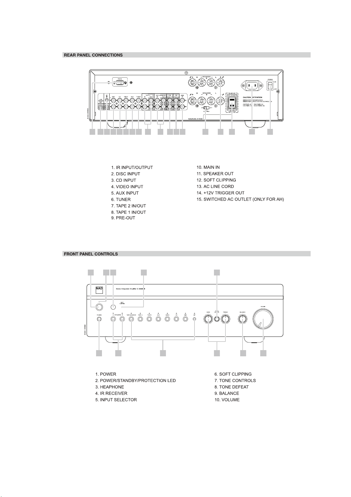
16 14 1 2 3 4 185 6 7 8 17 9 10 12 11 15
INPUT
16. RS-232 INPUT
(TAPE MONITOR)
(2)
17. PRE OUT 1
18. ON OFF POWER (AC) SWITCH
13
1 2
4 6 8
3 11 5 7 9 10
11. SPEAKERS A & B
LED
5
Page 6

SPECIFICATIONS
POWER AMPLIFIER SECTION
STEREO MODE
CONTINUOUS AVERAGE POWER 80 W (19 dBW)
OUTPUT INTO 8 OHMS OR 4 OHMS
(Min. power per channel, 20 Hz – 20 kHz,
with no more than rated distortion)
Rated Distortion 0.02%
(THD 20 Hz – 20 kHz)
Clipping power 90 W
(maximum continuous power per channel 4 and 8).
IHF dynamic headroom: at 8 ohms + 2.4 dB
at 4 ohms + 4.4 dB
IHF dynamic power
(maximum short term power per channel)
8 ohms: 160 W (20.4 dBW)
4 ohms: 220 W (22.0 dBW)
2 ohms: 270 W (23.2 dBW)
Damping factor > 100
(ref. 8 ohms 1 kHz)
Input Impedance R = 20 kohms
C = 1 nF
Input sensitivity (for rated output into 8 ohms) 950 mV
Voltage gain 29 dB
Frequency response 20 Hz – 20 kH
Signal / Noise ratio, A-weighted 100 dB ref. 1 W
THD + Noise < 0.02%
(Total Harmonic Distortion, 20 Hz – 20 kHz,
from 250 mW to rated output)
SMPTE I.M. < 0.01%
(Intermodulation Distortion, 60 Hz + 7 kHz, 4:1,
from 250 mW to rated output)
0.1 dB
119 dB ref. 50 W
IHF I.M. < 0.01%
(CCIF IM Distortion, 19 + 20 kHz at rated output)
Headphones Output Impedance 220 ohms
6
Page 7

PREAMPLIFIER SECTION
LINE LEVEL INPUTS
(Disk, CD, Video, Auxiliary, Tuner, Tape 1,Tape 2)
Input impedance (R and C) 200 kohms + 100 pF
Input sensitivity (ref. rated power) 310 mV
Maximum input signal 6 V
Signal / Noise ratio, A-weighted 97.0 dB ref. 1W
(from CD Input to Speakers Output, Volume Setting
for 500mV in , 8ohms 1W out)
Signal to noise ratio preamp out, IHF “A” weighted 110 dB re 500mV
Frequency response, 20 Hz – 20 kHz < +/-0.1 dB (tone defeat on)
< +/-0.2 dB (tone defeat off)
THD + Noise, SMPTE IM < 0.01% at 5 V out
LINE LEVEL OUTPUTS
Pre-amp output impedance 80 ohms
Tape output impedance Source Z + 1kohms
Maximum output level pre-amp out : > 11 V
Tape-out : > 10 V
CONTROLS
Treble +/- 5 dB at 10 kHz
Bass +/- 8 dB at 100 Hz
IR IN and OUT
Input Resistance > 10 kohms
Input Voltage Min 5 V
Output Resistance < 30 ohms
TRIGGER Out
Output Current 50 mA
Output Voltage 12 V
DIMENSIONS AND WEIGHTS
Net Weight 6.5 kg ( 14.3 Ib)
Shipping Weight 8 kg ( 17.6 Ib)
DIMENSION (W×H×D) 435× 116 × 292MM
7
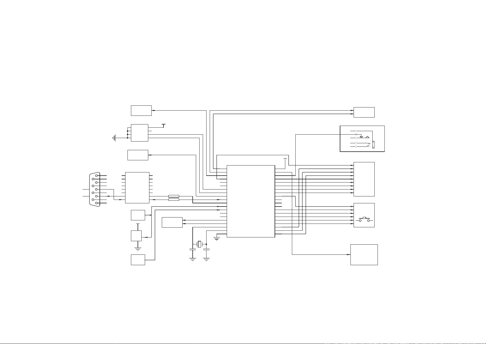
Page 8
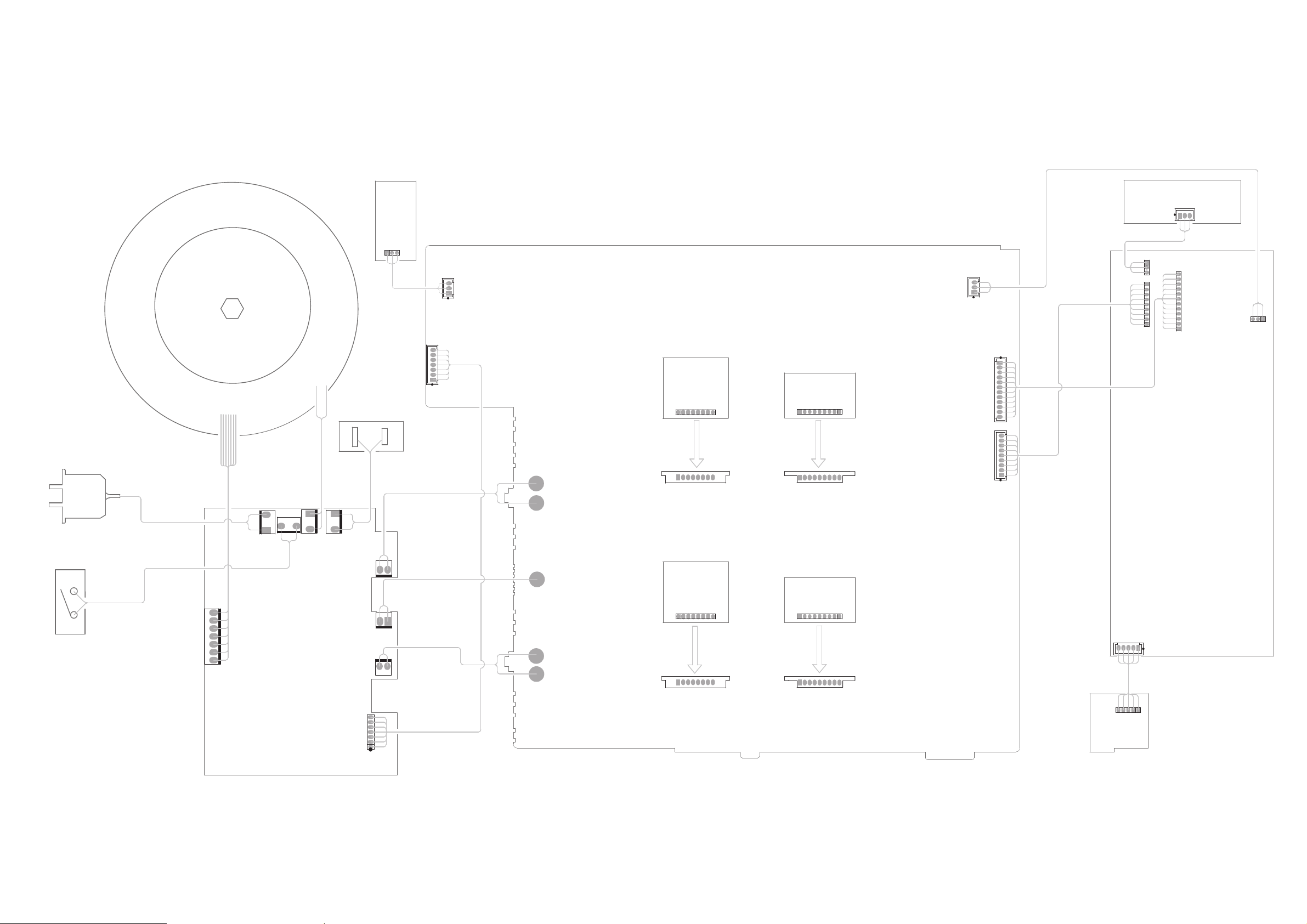
REMROFSNART
BOARDHEADPHONE
MARGAID GNIRIW
62#GWA 8642LU
DRAOB 232SR
87BC
62#GWA 8642LU
54ZC
AC POWER PLUG
POWER SWITCH
53BC
62#GWA 8642LU
CB45
74BC
DRAOB NIAM
87ZC
67ZC
17ZC
57ZC
UL2468 AWG#26
01-35502-00
)HA(TELTUO CA
DRAOB L-DMS-PMA
12ZC
01-35504-00
16ZC
tresnI
UL1672 AWG#22
65BC
CB55
75BC
81#GWA 2761LU
15BC
UL1672 AWG#18
95BC
CB54
CB58
UL3266 AWG#18
81#GWA 2761LU
41#GWA 2761LU
81#GWA 2761LU
DRAOB REWOP
12BC
01-35503-00
11
ZC
DRAOB R-DMS-PMA
01-35504-00
16ZC
tresnI
DRAOB DMS PMA PMAERP
tresnI
23BC
DRAOB DMS PMA PMAERP
tresnI
13BC
43BC
UL2468 AWG#26
KEY BOARD
37BC
CB52
62#GWA 8642LU
11BC
35BC
62#GWA 8642LU
33BC
37ZC
DRAOB YBDNATS
8
Page 9
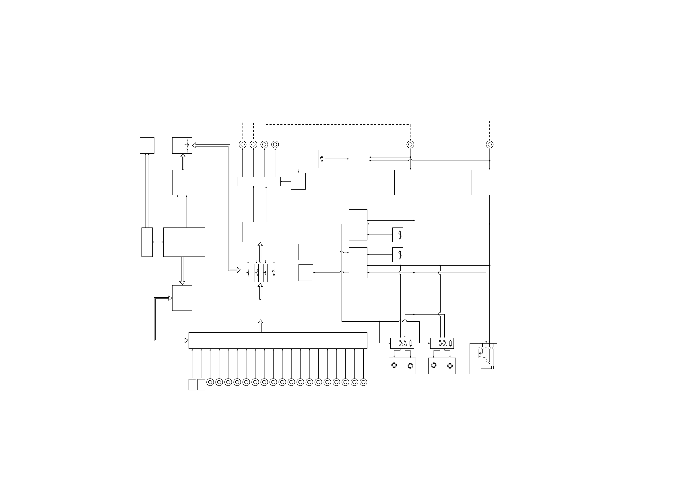
MARGAID KCOLB
DB9
RS232
SP232EEP-L
RT33
VOLUME
CONTROL
VOLUME CONTROL
CIRCUIT (REMOTE)
VOL-
VOL+
MCU
AT89S52
CIRCUIT
(BY RELAYS)
INPUT SELECTION
PRE-OUT2 L
PRE-OUT1 L
MUTE
TUO ˅
DMS
ELUDOM PMA MPAERP
BASS
TREBLE
RT31
RT32
RT34
˅
DMS
ELUDO
M PMA MPAERP
PRE-OUT1 R
Y
RELA
˄
BALANCE
SW31
˄ NI
PRE-OUT2 R
TONE DEFEAT
MCU
MUTE
CONTROL
CIRUIT
MIRROR
CURRENT
SCR
CIRCUIT
SOURCE
CIRCUIT
CONTROL
S41
TRIG I-V
SOFT CLIPPING
CONTROL CIRCUIT
(IC44)
MODULE
PROTECTION
ISC CIRCUIT
(IC43,TL082D)
R439
POSISTOR
R467
POSISTOR
MAIN IN R
CIRCUIT L
POWER AMP
(90 DEGREE C)
(80 DEGREE C)
MAIN IN L
CIRCUIT R
POWER AMP
MP L
MP R
DISC L
DISC R
CD L
shctiwS yaleR
CD R
VIDEO L
VIDEO R
AUX L
AUX R
TUNER L
TUNER R
TAPE1 IN L
TAPE1 IN R
TAPE1 OUT L
TAPE1 OUT R
TAPE2 IN L
TAPE2 IN R
9
TAPE2 OUT L
TAPE2 OUT R
RL12/2
F1AA012V
SPK A R
SPK A L
RL12/1
SPK B R
SPK B L
HEADPHONE
14KJ
Page 10
MARGAID NOITCENNOC ROSSECORPORCIM
etuM
tiucriC
17CI
1
CN
2
3
77ZC
5
1
9
2
4
3
8
4
01
11
3
5
7
6
2
7
6
8
1
9 BD
ccV
CN
CN
CN
LCS
ssV4ADS
10C42
teseR
tiucriC
67CI
+1C
CCV
+V
DNG
-1C
TUO1T
+2C
NI1R
-2C
TUO1R
-V
NI1T
TUO2T
NI2T
NI2R
TUO2R
L-PEE232PS
TUO RI
TIUCRIC
V5+
27CI
3
1
2
L06U1SI
NI RI
TIUCRIC
V5+
8
7
6
5
37CI
1
0.1P
2
61
51
41
31
21
11
01
9
01567R
807R
01
B/A rekaepS
tiucriC lortnoC
17Y
zHM2950.11
97C
p72
017C
p72
1.1P
3
2.1P
4
3.1P
5
4.1P
6
5.1P
7
6.1P
8
7.1P
9
TSR
01
11
21
31
41
4.3P/0T
51
5.3P/1T
61
71
81
91
02
6.3P/RW
7.3P/DR
2LATX
1LATX
SSV
25S98TA
0.3P/DXR
1.3P/DXT
2.3P/0TNI
3.3P/1TNI
V5+
04
DDV
93
0DA/0.0P
83
1DA/1.0P
73
2DA/2.0P
63
3DA/3.0P
53
4DA/4.0P
43
5DA/5.0P
33
6DA/6.0P
23
7DA/7.0P
13
AE
03
ELA
92
NESP
82
51A/7.2P
72
41A/6.2P
62
31A/5.2P
52
21A/4.2P
42
11A/3.2P
32
01A/2.2P
22
9A/1.2P
12
8A/0.2P
emuloV
tiucriC
17ENOHP
NI dopI
noitceles tupnI
ybdnatS dnA
tiucriC lortnoC
noitceles tupnI
syeK
ylppuS rewoP V81enil lortnoc ybdnaS
tiucriC lortnoC
10
Page 11
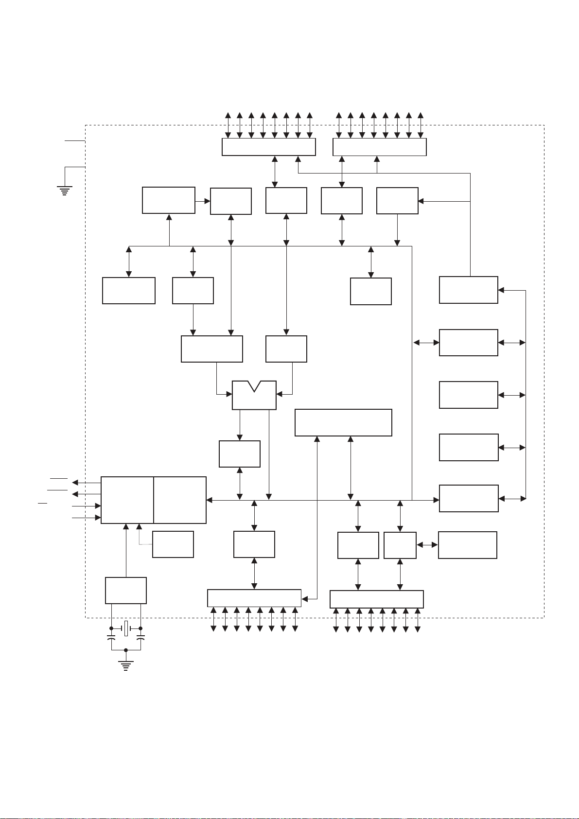
AT89S52
KEY BOARD IC73
V
CC
GND
B
REGISTER
RAM ADDR.
REGISTER
P0.0 - P0.7
PORT 0 DRIVERS
RAM
ACC
TMP2 TMP1
PORT 0
LATCH
PORT 2 DRIVERS
PORT 2
LATCH
POINTER
P2.0 - P2.7
FLASH
STACK
PROGRAM
ADDRESS
REGISTER
BUFFER
PSEN
ALE/PROG
EA / V
RST
PC
ALU
INTERRUPT, SERIAL PORT,
AND TIMER BLOCKS
PSW
TIMING
AND
PP
CONTROL
OSC
INSTRUCTION
REGISTER
WATCH
DOG
PORT 3
LATCH
PORT 3 DRIVERS
P3.0 - P3.7
PORT 1
LATCH
PORT 1 DRIVERS
P1.0 - P1.7
ISP
PORT
INCREMENTER
PROGRAM
COUNTER
DUAL DPTR
PROGRAM
LOGIC
11
Page 12
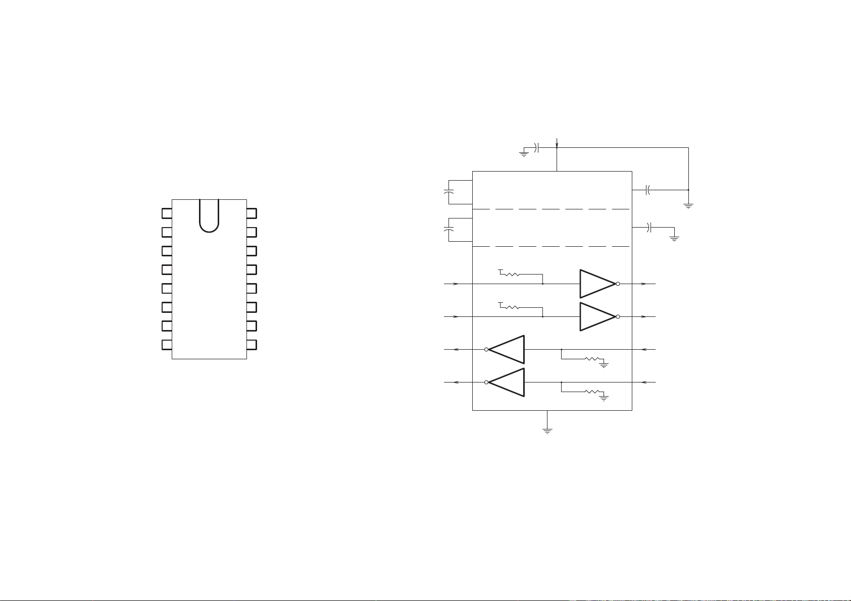
PEE232PS
67CI :DRAOBYEK
1
+1C
Fu1.0
3
-1C
1
2
+V
3
-1C
61+1C
CCV
51
DNG
41
TUO1T
4
+2C
Fu1.0
5
-2C
TUPNI V5+
Fu01
61
CCV
2
V01+ ot V5+
relbuoD egatloV
V01- ot V01+
retrevnI egatloV
+V
Fu1.0
6
-V
fu1.0
4
+2C
5
-2C
6
-V
7
TUO2T
31
NI1R
11
21
TUO1R
11
NI1T
01
NI2T
98
TUO2RNI2R
NI1T
01
NI2T
21 31
TUO1R
TUO2R NI2R
smhoK004
smhoK004
1T
2T
1R
smhoK5
2R
smhoK5
51DNG
41
7
89
TUO1T
TUO2T
NI1R
12
Page 13

24C01
KEY BOARD IC71
PIN CONFIGURATION
FUNCTIONAL BLOCK DIAGRAM
8
Vcc
5
SDA
6
SCL
7
WP
SLAVE ADDRESS
REGISTER &
COMPARATOR
1
NC
2
NC
3
NC
4 5
VSS
CONTROL
LOGIC
8
VCC
7
NC
6
SCL
SDA
HIGH VOLTAGE
GENERATOR,
TIMING & CONTROL
REDOCED
X
EEPROM
ARRAY
GND
WORD ADDRESS
COUNTER
Y
DECODER
4
ACK
nMOS
Clock
DI/O
DATA
>
REGISTER
13
Page 14

ALIGNMENT PROCEDURES
I. INITIAL
A. LOWEST VOLUME ADJUSTMENT
1. Tune the volume pot to lowest state.
2. Input a high voltage signal such as 5V from CD input.
3. Connect a oscilloscope to L channel binding posts.
4. Observing the oscilloscope,adjust VR301,make the output of speakers become to the
lowest level.
5. Adjusting VR302,make R channel output become to the lowest level by same way.
B. IDLING CURRENT
1. Power on
2. Running 5 minutes with no signal
3. Connect a DC voltmeter toTP1 and TP2 ,adjust VR22/VR23 for 6mV reading on voltmeter.
4. Connect a DC voltmeter toTP3 and TP4 ,adjust VR12/VR13 for 6mV reading on voltmeter.
C.ISC CIRCUIT ORIGINAL ADJUSTING
Adjust the pot VR3 to make the DC voltage of the point of TP10 to the same as TP11
II. FINAL ADJUSTMENT
Repeat procedure A,B and C for the lowest volume level, idling current alignment
and ISC original level respectively.
C355BEE
TP1
VR22
VR23
TP2
TP3
MAIN BOARD
TP10 TP11
VR3
VR301 VR302
VR12
TP4
VR13
VR304 VR304
14
Page 15

)4/1(MARGAID SCITAMEHCS
0.1mV TIUCRIC YLPPUS REWOP
0.1mV DRAOB REWOP:2-BCP
265R
135R
EC %5 W5/50.0
5101A
015Q
335R
765R
M1
K033
45BC
V55+
2
DER
V55-
1
ETIHW
25BC
2
DER
1
ETIHW
85BC
2
1
35BC
7
6
V-I
5
4
3
2
1
V55+
V55-
GIRT
.TED CA
V44+
V44-
K1
235R
022
95Q
5101A
435R
2K2
665R
7K4
165R
001
715Q
5101A
135D
R005-151TB
715C
%01 V36/Fu00022
815C
%01 V36/Fu00022
565R
001
915Q
5101A
465R
K22
5181C
025Q
315D
4004N1
15CI
V5+
312
625C
Fu001
365R
K22
855R
K1
!!
15C
25C
55D
D8UBK
235D
R005-151TB
815Q
0.5-7111SMA
065R
5181C
K1
955R
K1
445R
K22
525C
V61/Fu0074
15D
D8UBK
325C
V05/u0033
425C
V05/u0022
25D
401BD
55F
Am005
V052/n01
V052/n01
%01
%01
V44+
65D
401BD
15F25F 45F 35F
V44-
.RIC REWOP EEB553C DAN
55BC
55ZC
3
3
2
2
1
3NOC
35C
45C
Fu33.0
4X V052/A3.6
65BC
V004/Fn7.4
3
2
1
3NOC
95BC
1
2
3
3NOC
75BC
3
1
3NOC
15BC
V14
1
V14
2
V0
3
V5.13
4
V5.13
5
V8
6
V0
7
7NOC
!
1
gniR etirreF
21*51*52
65ZC
1
2
!
3
3NOC
95ZC
3
2
!
1
3NOC
75ZC
1
2
!
3
3NOC
15ZC
DER
7
OIV
6
KLB
5
GRO
4
YRG
3
2
1
7NOC
25WS
1
1
2
2
104T
teltuo CA
!
DROC REWOP CA
HCTIWS REWOP
)noisreV CAV021 roF(
remrofsnarT
remrofsnart fo renni eht
otni 031.10S rekaerb lamreht a tresnI
15
Page 16

SCHEMATIC DIAGRAM(2/4)
PREAMP CIRCUIT Vm1.0
PCB-1:MAIN BOARD Vm1.0
DISC
VIDEO
TUNER
TAPE2
TAPE1
REC1
DISC
VIDEO
TUNER
TAPE1
REC1
CD
AUX
REC2
Ipod-L
Ipod-R
CD
AUX
TAPE2
REC2
RCA31A
RCA31C
RCA31E
RCA32A
RCA32C
RCA32E
RCA33A
RCA33C
RCA33E
CB35
CON3
RCA31B
RCA31D
RCA31F
RCA32B
RCA32D
RCA32F
RCA33B
RCA33D
RCA33F
RI7
330,5%
Mute Relay
TAPE1
TAPE2
TUNER
AUX
VIDEO
CD
DISC
IPOD
+12V
IROUT
IRIN
R399
100
RL310A
R398
100
+12V+12V
+5V
+18V
-18V
Speak B
Speak A
Standby
Protection
Soft Cliping
CB31
TO CZ76
PHONE1B
PHONE1A
IR OUT
GIRT V21
PHONE2
+12V Trigger
RL310B
TO CZ71
CB34
12
11
10
9
8
7
6
5
4
3
2
1
IR IN
9
8
7
6
5
4
3
2
1
R347
100K
R348
100K
C363
100pF
C364
100pF
RCA34C
Pre-out 2 L
RCA34A
Pre-out 1 L
RCA34D
Pre-out 2 R
RCA34B
Pre-out 1 R
C314
100p
C31
100p
C33
100p
C35
100p
C37
100p
C39
100p
C311
100p
C313
100p
C315
100p
C317
100p
C304
100P
C305
100P
C32
100p
C34
100p
C36
100p
C38
100p
C310
100p
C312
100p
C316
100p
C318
100p
RL31B
RL32B
RL33B
RL34B
RL35B
RL36B
RL37B
RL38B
RL39B
RL39A
RL31A
RL32A
RL33A
RL34A
RL35A
RL36A
RL37A
RL38A
R345
220K
MF
LOW NOISE AMP
R346
220K
MF
CB32
IN MODULE
C355BEE RELAY CONTROL CIR.
D37
D38
D39
D310
D311
1N4148
1N4148
1N4148
1N4148
RL31C RL32C RL33C RL34C RL35C RL36C RL37C RL38C
CSID
STUPNI HC-L
C319
0.1u 10%
C324
47u/35
1
+18V +18V
2
3
4
5
6
7
8
9
-18V
C323
47u/35
STUPNI HC-R
C320
0.1u 10%
DC
R365
C365
R320
TONE DEFEAT SW
OEDIV
C325
47u/25
C321
0.1U
R323
R319
N.I.
750 MF
TONE DEFEAT SW
30K
68pF
C326
47u/25
C322
0.1U
3K3 MF
R322
R324
750 MF
N.I.
XUA
C330
0.1u 5%
63V
D312
1N4148
1N4148
RENUT
C355BEE TONE CONTROL CIR.
R325
390 MF
R321
3K3 MF
C327
63V
22n 5%
TOP ELBERTTOP ELBERT
R363
51K
A13TR
AK01
C329
0.1u 5%
63V
R327
180 MF
SW31A
1
OFF
2
3
ON
R391 560 1%
R392 560 1%
R326
390 MF
C328
22n 5%
B13TR
R364
AK01
51K
R328
180 MF
SW31B
4
5
OFF
6
ON
R402
10K
C301
10uF/50V
Q401
A1015
R403
1K
R361
VR303
30K
R362
VR304
30K
Q402
C1815
N.I.
N.I.
D313
1N4148
2EPAT
2
u22.0133C
2
V36,%5
1
1
%5,V36,u1
333C
C335
N.I.
R366N.I.
C366 N.I.
V36
%5 u22.0
233C
%5,V36,u1
433C
C336
N.I.
+5V
VOLUME CONROL
RT33C
20KB
- +
M
C417
4u7/25V
R406
1K
C303
220p
R329
1K5 MF
A23TR
R331
390 MF
R330
1K5 MF
B23TR
R332
390 MF
1EPAT
AK01
TOP SSAB
D316
1N4148
TOP SSAB
AK01
C418
4u7/25V
R407
1K
C302
220p
+12V
D317
1N4148
yaleR etuM
RL39C
DOPI
TOP EMULOV
A33TR
BY MOTOR
BK02
C337
0.1U
TOP ECNALABTOP ECNALAB
NM K02
A43TR
C339
1u/16
CB33
1
47uF/35V
2
C131
3
4
5
6
7
C231
8
47uF/35V
9
OUT MODULE
LOW NOISE AMP
C338
0.1u
NM K02
B43TR
C340
1u/16
BY MOTOR
RT33B
20KB
VOLUME POT
R404
10K
Q403
A1015
R405
1K
Q404
C1815
RL310C
-18V
RI4
4.7K
C345
0.1uF
C341
47u/25
C349 N.I.
R387
20K
R383
560 1%
R384
560 1%
R388
20k
C350 N.I.
C346 0.1uF
C342
47u/25
QI1
2SC1815
RI2
1K
QI2
2SA1015
+5V
RI510K
RI1 10K
VR301
R385
R386
VR302
+12V
+5V
RI6
10K
C362
10n
RI3
33
R2
10
C3 0.1uF
R335
68
R333
4.7K
100
1.8
1.8
100
R336
68
R334
4.7K
+5V
+18V
-18V
Soft Cliping
Protection
Standby
+5V
VOL+
VOL-
R31
470
R349
1M
R33
470
R351
1M
R35
470
R353
1M
R37
470
R355
1M
R39
470
R357
1M
R311
470
R337
1M
R313
470
R338
1M
R315
470
R339
1M
R317
470
R393
470
R394
1M
3
2
1
R396
470
R395
1M
R32
470
R350
1M
R34
470
R352
1M
R36
470
R354
1M
R38
470
R356
1M
R310
470
R358
1M
R312
470
R341
1M
R314
470
R342
1M
R316
470
R343
1M
R318
470
PREAMP MODULE CIRCUIT Vm1.0 Low Noise Amp In and Out Module part number 01-35504-00 a non-servicable part
PCB-6:PREAMP SMD BOARD Vm1.0
Q65
CZ61
CON9
C68
0.1u 20%
+18V
1
LOUT
2
LIN-
3
LIN+
4
GND
5
RIN+
6
RIN-
7
ROUT
8
-18V
9
R64
2.2M
R62
220
C62
220p
C610
100p
R68
1K
26Q
C67
0.1u 20%
A1312-GR
Q69
C3324-GR
R612
RG 902KS2
C64
1K
22p
C612
R622
1nF
1K
Q611
C3324-GR
R624
620
R614
10K
R610
430 2%
Y-1882CS2
86Q
R616
10
R617
10
Q66
2SA1201-Y
16
R620
10
C66
0.1u 20%
R63
2.2M
Q63
A1312-GR
R67
1K
C61
220p
RG 902KS2
R61
220
C69
100p
16Q
C65
0.1u 20%
C613
Q610
C3324-GR
Q67
R611
C63
1K
22p
R623
1nF
1K
R625
620
R613
10K
2SC2881-Y
R615
10
R69
430 2%
RG-4233C
216Q
R618
10
R619
10
Y-1021AS2
46Q
Page 17

0.1mV TIUCRIC PMA
(MARGAID CITAMEHCS3)4/
0.1mV DRAOB NIAM:1-BCP
1/21C
V52/Fu01
911C
V36 %01 n22
851R
k2.2
v36 %01 u1.0
V36 %01 n22
852R
k2.2
V55+
1/21Q
5101A
V21+
:noitcetorP taeH revO
This will shut down the unit
C°.09 revo si knistaeh eht
This will also shut down the
unit when the unit enters the
e.dom ybdnats
921C
Fp5.1
V44+
724R
PF W1/22
414Q
5181C
314Q
0962CSK
594R
914C
015
Fu01
GIRT V21
:tiucriC CSI
rewop eht hctiws tI
egatlov rewol ot ylppus
d.aol eht nehw
eht ro ,wol si ecnadepmi
eht no erutarepmet
C°.08 revo si knistaeh
V81+
834R
K81
no erutarepmet eht nehw
V81+
824R
2K2
414R
C49
47u/25V
2K2
114C
Fu1.0
FM
924R
344C
1K5
Fu1.0
224Q
766D
324Q
0422C
494R
21
644C
Fu01
V81-
384R
924C
V52/u01
K072
774R
K74
374R
K15
624C
V52/u01
094R
K001
194R
K001
YBDNATS
734R
K74
34D
24D
934R
ROTSISOP
784R
K81
884R
K81
024D
914D
8414N1
8414N1
8414N1
214Q
5181C
8414N1
C eerged 09=0T
224C
214R
C410
47u/25V
K2
274R
K074
674R
K22
8
4
2/21R
FM
K1474R
034C
V52/u01
7
B34CI
D280LT
134C
V52/u01
5
3 4
1 2
V44+
44CI
1234567
234C
u22.0
214C
u1.0
V81+
6
5
K1
V81-
V61/u033
.RIC NOITCETORP
.RIC YLPPUS
744C
V05/Fu01
694R
%1,K26
794R
%1,K01
103CI
134ZA
114R
086
YBDNATS
104R
314R
7K4
086
14C
Fu1.0
014R
086
84C
V52/u01
074R
174R
K01
K01
1
714D
814D
8414N1
8414N1
TIUCRIC CSI
1/21LR
FA4SH2-420/F511-XQJ
6
214D
8414N1
V44+
V81+
144R
2K2
W2/1,K7.4
eludoM noitcetorP
8
C421
0.47uF/50V
024C
V61/u001
14Q
54R
0962CS2
74C
V05/u74
94R
086
54C
p22
304D
8414N1
64C
p22
24Q
01PT
2
3
A34CI
D280LT
11PT
824C
V52/u01
5 6
3
FA4SH2-420/F511-XQJ
1 2
2/21LR
044R
034R
W1/K1
424Q
5181C
134R
k01
SF W5.0/33
314C
V53/u022
74R
086
34Q
5181C
44Q
5101A
84R
086
414C
V53/u022
64R
SF W5.0 / 33
0221AS2
284R
524C
7K4
V52/u01
874R
K001
974R
K001
084R
3K4
4
V44+
314D
8414N1
804R
644R
K65
234R
K01
034D
904R
544R
k65
K65
k65
334R
W1/K1
524Q
5181C
244R
K01
k01
8414N1
V44+
14R
086
34R
086
34C
V36/u022
44C
V36/u022
44R
086
24R
086
394R
k081
3RV
K01
V81+
220/2W FP
220/2W FP
R453
R452
54BC
1
2
3
434R
924D
8414N1
V81+
V5+
V44-
V-I
.TED CA
GIRT CSI
V81+
824D
964R
864R
8414N1
K01
K22
124Q
5181C
764R
C eerged 08=0T
STSOP GNIDNIB
A KPS
TUO R
4
3
2
1
TUO L
B KPS
TUO R
4
3
2
1
TUO L
54ZC
1
2
3
454R
W2,001
V81-
V21+
V55-
14KJ
554R
W2,001
YBDNATS
ybdnatS
A kaepS
B kaepS
noitcetorP
gnipilC tfoS
V5+
V81+
V81-V5+
V21+
V55-
*
74BC
1
2
3
4
5
6
7
NIP7
30D023C8N
TEKCOS SENOHP
0.1mV TIUCRIC ENOHPDAEH
0.1mV DRAOB ENOHPDAEH:7-BCP
031R
SF W1/28
101D
431R
V81+
451R
01
31C
V53/u01
91R
11BC
V81+
21
HC-R NI-NIAM
F43ACR
11R
074
21R
K022
74Q
5101A
001
V55+
014D
024R
K63
V02
1
2
3
A14S
NO
V55-
114D
V02
E43ACR
K3.1
FFO
K3.1
4
5
6
B14S
K3.1
K3.1
124R
K63
001
64Q
5181C
HC-L NI-NIAM
12R
074
22R
K022
11C
V61/u01
41R
001
71C
V36/Fu1.0
84Q
5181C
51R
K22
814R
224R
424R
524R
324R
614R
914R
001
514C
V52/u01
614C
V52/u01
714R
001
54Q
5101A
42R
72C
001
V36/Fu1.0
12C
V61/u01
52R
K22
21
11
11
01
01
9
9
8
8
7
7
11ZC
6
6
5
5
4
4
3
3
2
2
1
1
V81-
21NOC
8NOC
.RIC GNIPILC TFOS
12BC
V81+
21
21
11
11
01
01
9
9
8
8
12ZC
7
7
6
6
5
5
4
4
3
3
2
2
1
1
V81-
8NOC
21NOC
%5,FM,k93
111R
Q12
A1312-GR
Q13
C3324-GR
21C
Fn1
R112
100,MF,5%
011R
%5,FM,k93
41C
V53/u01
551R
01
V81-
941R
FM %1 4/1,86
V81+
452R
01
32C
V53/u01
92R
%5,FM,k93
112R
Q22
A1312-GR
Q23
C3324-GR
22C
Fn1
R212
100,MF,5%
012R
%5,FM,k93
42C
V53/u01
552R
01
V81-
942R
FM %1 4/1,86
%5,FM,K93
101R
301Q
RG-4233C
911R
301C
V61/Fu22
R102
R103
220k,MF,5%
82,MF,5%
Q101
C3324-GR
41Q
RG-4233C
%5,FM,001
511R
51
611R
51
51Q
RG-2131A
5%
Q102
A1312-GR
R106
401C
V61/Fu22
302C
V61/Fu22
%5,FM,001
402C
V61/Fu22
82,MF,
R104
220k,MF,5%
312-GR
Q104
A1
501R
%5,FM,k93
%5,001951R
Fu00121L
%5,FM,K93
102R
302Q
R202
R203
220k,MF,5%
82,MF,5%
Q201
C3324-GR
42Q
RG-4233C
512R
51
612R
51
52Q
RG-2131A
Q202
A1312-GR
R206
82,MF,5%
R204
220k,MF,5%
312-GR
Q204
A1
502R
%5,FM,k93
%5,001952R
Fu00122L
%5,FM,28
31D
8414N1
61Q
5101A
81C
p93
Q18
2SB1026-DM
121R
FM,K001
321R
K74
Q19
91C
2SD1419-DM
p93
RG-4233C
82C
p93
92C
p93
V55-V55+
R122
100K,MF,5%
71Q
5181C
41D
8414N1
021R
%5,FM,28
Fn1
421C
961R
033
912R
%5,FM,28
32D
8414N1
62Q
5101A
Q28
2SB1026-DM
122R
FM,K001
322R
K74
Q29
2SD1419-DM
R222
72Q
100K,MF,5%
5181C
42D
8414N1
022R
%5,FM,28
Fn1
422C
033962R
2M1
51D
8414N1
61D
8414N1
0.1mV TIUCRIC R ELUDOM DMS-PMA
0.1mV DRAOB R DMS PMA :5-BCP
432R
2M1
52D
8414N1
62D
8414N1
0.1mV TIUCRIC L ELUDOM DMS-PMA
0.1mV DRAOB L DMS PMA :4-BCP
V55+
V55-
261R
8414N1
K1
51C
V36/Fu022
361R
K1
711Q
8414N1
8414N1
8414N1
8414N1
811Q
0422CS2
861R
K1
262R
K1
362R
K1
812Q
0422CS2
862R
K1
Note:
079AS2
461R
561R
K01
K01
661R
6K5
10uF
10uF
C128
C123
11CI
134ZA
761R
K1
102D
8414N1
712Q
079AS2
462R
562R
K01
K01
R266
5K6
12CI
C228 10uF
C223 0.1uF
134ZA
762R
K1
Heatsink Assembly 02-35500-00 includes R439, Q114, Q115, Q116, Q214, Q215, Q216, & R467
201D
301D
61C
V36/Fu022
131R
SF W1/28
032R
SF W1/28
52C
V36/Fu022
202D
302D
62C
V36/Fu022
132R
SF W1/28
621R
3K3/2W FP
330/0.5W FP
3.3/0.5W FP
Q110
KSA1220
Q111
KSC2690
3.3/0.5W
330/0.5W
3K3/2W
PF W2/3K3
171R
028
911Q
0962CS2
11D
V7.4
011C
V52/u74
111C
V52/u74
721R
K2
21D
071R
V7.4
K2.2
731R
01
PF W2/3K3
R132
R128
R124
R125
R129
R133
241R
%5,FM,22
701R
%5,FM,93
%02,V001,p074
211C
631R
01
31RV
831R
034
SF
211Q
SF
3PT
21RV
441R
002
721C
.I.N
541R
611Q
0962CSK
4PT
931R
214
311Q
311C
801R
%02,V001,p074
%5,FM,93
341R
%5,FM,22
411C
1/21R
8K6
u1.0
411Q
71D
1212AS2
8414N1
251R
K22
841R
K65
741R
1715CS2
K1
EC W3/860.0
EC W3/860.0
0391AS2
2SC5949
Q115
11Q
5181C
811C
V36 %01 u1.0
021C
641R
511C
151R
%01 n22
SF W1/01
11L
Hu5.0
051R
651R
PF W1/1
K074
FM,%1,W1,8K1
u1.0
994R
W4/1,1
V55-
121C
%5,V36,Fu1
061R
48
%5,K1
3
2
V81-
1
V81+
161R
A14CI
%5,K1
D280LT
751R
221C
K074
%5,V36,Fu1
R .RIC PMA REWOP
V55+
622R
W2/3K3
R232
3K3/2W FP
R228
330/0.5W FP
912Q
R224
3.3/0.5W FP
Q210
KSA1220
Q211
KSC2690
R225
3.3/0.5W
FP
R229
330/0.5W
R233
3K3/2W FP
172R
0962CS2
028
12D
012C
V7.4
V52/u74
112C
V52/u74
722R
W2/3K3
K2
22D
072R
V7.4
K2.2
732R
01
SF
242R
%5,FM,22
702R
%5,FM,93
%02,V001,p074
212C
632R
01
SF
32RV
832R
034
212Q
1PT
22RV
442R
002
722C
.I.N
542R
612Q
0962CSK
2PT
932R
214
312Q
312C
%02,V001,p074
802R
%5,FM,93
342R
%5,FM,22
412C
V36 %01 u1.0
412Q
O-1212AS2
252R
K22
72D
8414N1
842R
1715CS2
742R
K1
EC W3/860.0
EC W3/860.0
0391AS2
Q215
2SC5949-O
12Q
K65
022C
V36
642R
512C
5181C
152R
812C
%01 n22
894R
SF W1/01
12L
Hu5.0
052R
PF W1/1
912C
FM,%1,W1,8K1
652R
122C
K074
%5,V36,Fu1
062R
48
%5,K1
5
6
u1.0
W4/1,1
V55-
V81-
7
V81+
162R
B24CI
%5,K1
D280LT
752R
222C
K074
%5,V36,Fu1
L .RIC PMA REWOP
DNG-5P
R-3PR-4P
L-1PL-2P
17
Page 18

SCHEMATIC DIAGRAM GREEN LED KEYBOARD AND GREEN LED STANDBY LED BOARD ASSEMBLY PART # 01-35599-00 BEFORE SERIAL NUMBER H95C355BEEG12811
C7110.1u 20%
717D
WA315
27Q
5181C
367C
Fu1.0
27CI
L06U1SI
V5+
REVIECER RI
37R
K01
CCV
3
LANGIS
1
2
DNG
9P
GNIDLEIHS
0.1mV TIUCRIC YBDNATS
0.1mV DRAOB YBDNATS :9-BCP
YBDNATS117S
.DNI NOITCETORP/REWOP
NEERGDER
Fu1.0267C
1
+1C
2
+V
3
-1C
4
+2C
5
Fu1.0467C
Fu1.0567C
-2C
6
-V
7
TUO2T
8
NI2R
10K
VOL+
VOL-
Speak A
Speak B
TA1
Remote Mute
R794
TA2
017D
37ZC
12345
5NOC
12345
37BC
5NOC
817D
8414N1
27R
17R
074
033
V5+
V21+
47Q
5181C
107R
2K2
667R
K7.4
517D
8414N1
037R
K51
37Q
5181C
Protection
IR IN
IR OUT
V5+
8414N1
117D
8414N1
V5+
217D
8414N1
317D
8414N1
KNILB RI
KNILB GNITUM
V5+
227C
R771 10K
R772 10K
67CI
CCV
DNG
TUO1T
NI1R
TUO1R
NI1T
NI2T
TUO2R
L-PEE232PS
10K
V5+
R795
R793 10K
Fu1.0
61
51
41
31
21
11
01
9
1
2
3
4
5
6
567R
807R
01
17Y
zHM2950.11
97C
p72
7
01
8
9
01
11
21
31
41
51
61
71
81
91
02
017C
p72
807D
NEERG
767C
n01
027Q
5181C
097R
7K4
027R
7K4
7K4
17CI
8
ccV
7
CN
6
LCS
5
10C42
0.1P
1.1P
2.1P
3.1P
4.1P
5.1P
6.1P
7.1P
TSR
0.3P/DXR
1.3P/DXT
2.3P/0TNI
3.3P/1TNI
4.3P/0T
5.3P/1T
6.3P/RW
7.3P/DR
2LATX
1LATX
SSV
907D
NEERG
867C
n01
n01
127Q
5181C
197R
7K4
677R
127R
7K4
027D
DI
IP
VI
AU
Speak A
CVITU
Speak B
Remote Mute
V5+
27C
Fu1.0
1
CN
2
CN
3
CN
ssV4ADS
37CI
25S98TA
V5+
167C
Fu1.0
077R
K01
04
DDV
93
0DA/0.0P
83
1DA/1.0P
73
2DA/2.0P
63
3DA/3.0P
53
4DA/4.0P
43
5DA/5.0P
33
6DA/6.0P
23
7DA/7.0P
13
AE
03
ELA
92
NESP
82
51A/7.2P
72
41A/6.2P
62
31A/5.2P
52
21A/4.2P
42
11A/3.2P
32
01A/2.2P
22
9A/1.2P
12
8A/0.2P
R779 10K
37D
OEDIV
yaleR etuM
417C
667C
n01
917Q
5181C
777R
7K4
847R
7K4
127D
8414N1
8414N1
Protection
517C
n01
97Q
5181C
147R
7K4
247R
7K4
947R
7K4
AU
227D
8414N1
77S
DC
97S
A KSEPS
017S
B KAEPS
10K
10K
10K
R773 10K
R774 10K
R775 10K
R787 10K
17D
XUA
617C
n01
017Q
5181C
347R
7K4
057R
7K4
TA2
10K
R780 10K
R781
R782
R783
R784
67D
2EPAT
717C
n01
117Q
5181C
447R
7K4
157R
7K4
TU
001967R
17L
0.1mV TIUCRIC YEK
0.1mV DRAOB YEK :3-BCP
Hu001
.I.N697R
.I.N967C
.I.N797R
.I.N
077C
001867R
10K
R785
V5+
87C
V61,Fu01
877R
K01
67S
2EPAT
57S
CSID
47S
1EPAT
367R
K01
17ENOHP
NI dopI
37S
OEDIV
27S
RENUT
17S
XUA
267R
K01
207R
K01
V21+
417D
327D427D
8414N1
V5+
987R
887R
R786 10K
27D
RENUT
NEERGNEERGNEERGNEERG
817C
n01
217Q
317Q
5181C
547R
7K4
257R
7K4
727R
627R
019
019
019
019
47D
CSID
DC
NEERG
917C
n01
5181C
647R
7K4
357R
7K4
57D
77D
417Q
5181C
1EPAT
NEERG
REBMA
1EPATCSIDRENUT2EPATXUAOEDIV DC
027C
n01
517Q
5181C
747R
7K4
457R
7K4
7K4
527R
957R
019
019
917D
PI
DOPI
127C
Fn01
067R
7k4
167R
617D
TFOS
NEERG
NEERG
817Q
5181C
V5+
C723
SOFT CLIPING
100uF/16V
+5V
C
DI
TA1
IP
767R
01
107PT
067C
857C
957C
Fu1.0
p001
p001
L
R
G
123
57ZC
53BC DRAOB NIAM OT
V5+
307R
2K2
717Q
5181CS2
467R
K01
yaleR etuM
1EPAT
2EPAT
RENUT
XUA
OEDIV
DC
CSID
DOPI
V21+
TUO RI
NI RI
GNIPILC TFOS
NOITCETORP
V5+
A kaepS
B kaepS
-LOV
+LOV
V21+
+12V
87BC
87ZC
3
1
2
2
1
3
3NOC
3NOC
1
2
3
4
5
6
7
8
9
01
11
21
67ZC
13BC OT
17ZC
43BC OT
9
8
7
6
5
4
3
2
1
1
6
11
2
7
3
01
8
4
77ZC
9
9 BD
5
297R
001
0.1mV TIUCRIC 232SR
0.1mV DRAOB 232SR :8-BCP
18a
Page 19

SCHEMATIC DIAGRAM BLUE LED KEYBOARD AND BLUE LED STANDBY LED BOARD ASSEMBLY PART # 01-35599-01 FROM SERIAL NUMBER H95C355BEEG12811 ONWARD
IC72
IS1U60L
2
R713
100
R714
VCC
3
1
GND
Q726
C3324
1K
1N4148
SIGNAL
R717
R715
D715
+5V
SHIELDING
0
1K
R73
10K
C762 0.1uF
C764 0.1uF
C765 0.1uF
D710
+5V
1N4148
D711
1N4148
+5V
D712
1N4148
D713
1N4148
IR BLINK
MUTING BLINK
R730
2K2
Protection
IR IN
IR OUT
L71
100uH
R796 N.I. R797 N.I.
C769 N.I.
C763
0.1uF
IC76
1
C1+
2
V+
3
C1-
4
C2+
5
C2-
6
V-
7
T2OUT
R2IN8R2OUT
SP232EEP-L
10K
R794
TA2
TA1
Speak A
Speak B
Remote Mute
VOL+
VOL-
VCC
GND
T1OUT
R1IN
R1OUT
T1IN
T2IN
10K
+5V
R795
AU
VI
Y71
11.0592MHz
CVITU
DI
C770
IP
C79
27p
C722
0.1uF
16
15
14
13
12
11
10
9
R708
10
+5V
Speak A
N.I.
R720
4K7
C767
10n
R765
10
R790
4K7
R772 10K
R721
4K7
10
11
12
13
14
15
16
17
18
19
20
C768
10n
1
2
3
4
5
6
7
8
9
R791
4K7
7
6
5
P1.0
P1.1
P1.2
P1.3
P1.4
P1.5
P1.6
P1.7
RST
RXD/P3.0
TXD/P3.1
INT0/P3.2
INT1/P3.3
T0/P3.4
T1/P3.5
WR/P3.6
RD/P3.7
XTAL2
XTAL1
VSS
D709
BLUE
Q721
C1815
Vcc
NC
SCL
24C01
Mute Relay
C766
10n
R776
4K7
D720
1N4148
Remote Mute
NC
NC
Vss4SDA
AT89S52
R777
4K7
R771 10K
R793 10K
C710
27p
D708
BLUE
Q720
C1815
Speak B
IC71
8
NC
+5V
C72
0.1uF
1
2
3
+5V
C761
0.1uF
IC73
D721
1N4148
Protection
R769 100
R768 100
Q719
C1815
P0.0/AD0
P0.1/AD1
P0.2/AD2
P0.3/AD3
P0.4/AD4
P0.5/AD5
P0.6/AD6
P0.7/AD7
P2.7/A15
P2.6/A14
P2.5/A13
P2.4/A12
P2.3/A11
P2.2/A10
P2.1/A9
P2.0/A8
R770
10K
40
VDD
39
38
37
36
35
34
33
32
31
EA
30
ALE
29
PSEN
28
27
26
25
24
23
22
21
R773 10K
R774 10K
R775 10K
R779 10K
R787 10K
D73
VIDEO
BLUE BLUE BLUE
VIDEO AUX TAPE2 TUNER DISC TAPE1CD
C714
10n
Q79
C1815
R741
4K7
R748
4K7
C771
1nF
D71
AUX
C715
10n
R749
4K7
AU
C772
1nF
R742
4K7
Q710
C1815
C716
10n
R743
1K
R750
1K
TA2
IR RECEIVER
C7110.1u 20%
C355BEE STANDBY BOARD Vm 1.2 PART # 01-35506-01
S711 STANDBY
R716
+12V
0
2
12345
R701
2K2
R766
4.7K
D717
3LED
Amber
2
Q725
C3324
R72
100
Q74
C1815
R711
10K
Q724
C3324
R712
3K3
4
12345
D718
1N4148
Q73
C1815
R704
R706
100
R707
R705
10K
1K
100
Q722
C3324
C1815
R710
2K2
Q72
Q723
C3324
R709
2K2
RED Blue
11334
CZ73
CON5
CB73
CON5
R71
62
+5V
D722
1N4148
R780 10K
D76
TAPE2
Q711
C1815
SPESK A
SPEAK B
10K
R781
R751
4K7
TU
S79
S710
10K
R782
C717
10n
R744
4K7
+5V
+12V
R
+5V
+12V
L
G
123
R703
2K2
Mute Relay
TAPE1
TAPE2
TUNER
AUX
VIDEO
CD
DISC
IPOD
CZ78
1
2
3
CON3
R767
10
C758
C759
100p
100p
CZ75
Q717
2SC1815
R764
10K
+12V
IR OUT
IR IN
SOFT CLIPING
PROTECTION
+5V
Speak A
Speak B
VOLVOL+
CB78
3
2
1
CON3
C760
0.1uF
TP701
1
2
3
4
5
6
7
8
9
10
11
12
CZ76
TO CB31
CZ71
TO CB34
9
8
7
6
5
4
3
2
1
1
6
2
11
7
3
10
8
4
CZ77
9
DB 9
5
R792
100
C78
10uF,16V
R778
10K
S77
CD
10K
R783
10K
R784
BLUE
Q712
C1815
5K1
R785
D72
TUNER
S76
TAPE2
S75
DISC
S74
TAPE1
+5V
R788
R786 10K
1K1
D74
DISC
BLUE
C718
10n
Q713
C1815
R745
4K7
R752
4K7
DI
R753
4K7
C
C719
10n
D723D724
R746
4K7
R789
1K1
+12V
S73
VIDEO
S72
TUNER
S71
AUX
D714
1N4148
R727
1K1
D77
CD
BLUE
Q714
C1815
R763
10K
PHONE71
Ipod IN
TO MAIN BOARD CB35
R762
10K
R702
10K
R726
1K1
D75
TAPE1
AMBER
C720
10n
Q715
C1815
R747
4K7
R754
4K7
TA1
R761
4K7
IP
BLUE
C721
10nF
R759
1K1
D719
IP
IPOD
R760
4k7
Q718
C1815
R725
1K1
D716
SOFT
BLUE
+5V
C723
100uF/16V
SOFT CLIPING
+5V
18b
REV
ECN NO.
DESCRIPTION
Add Q722---Q726,R704---R707,R709---R717
Change D717 to tri-color
Change R71 to 62ohms,R72 to 100ohms,R730 to 2K2
Change R743,R750 to 1K,R785 to 5K1
Change R725 R726,R727,R759,R788,R789to 1K1
Change LED on D71~D77, D708, D709, D716, D719
from green L-314GD to blue LJR3BD045.
Blue LED Keyboard Assembly 01-35599-01
DateP9APPRO
090416
090416
090416
090416
090416
090416
NAD ELECTRONICS
INTERNATIONAL
THE INFORMATION CONTAINED IN THIS DRAWING IS THE SOLE PROPERTY OF NAD
ELECTRONICS INTERNATIONAL. ANY REPRODUCTION IN PART OF WHOLE WITHOUT THE
WRITTEN PERMISSION OF NAD ELECTRONICS INTERNATIONAL IS PROHIBITED.
Document
Number:
Project:
Date:
C355BEE
Date: Date:
Sheet:
State:
Date:
Page 20

0.1mV DRAOB NIAM:1-BCP
812C
J185
912C
J178
TFEL B KPS
R446
CB45
TFEL A KPS
14S
4J
R408
J8
2/21LR
*
R452
R251
74BC
R431
R432
GIRT
TED CA
V-I
V44+
V44-
DNGD
V5+
R442
D430
12L
052R
R434
Q424
Q425
334R
034R
D429
314D
R498
Heatsink Assembly 02-35500-00 : With R439, Q115, Q114, Q119, Q219, Q214, Q215, R467
3J
B KPS
STSOP GNIDNIB
DNG
21J
DNG
1/21LR
J6
J180
214D
354R
TUO-L
THGIR
911C
811C
2J
A KPS
THGIR
*
J10
11L
TUO-R
151R
051R
904R
544R
384R
784R
094R
194R
884R
5J
)DNG(
43ACR
C363
R347
R348
J13
914D
024D
361J
R399
R335
R333
C364
7J
013LR
R398
R336
R334
713D
33ACR
R338
R342
R317
R318
R339
R343
R316
R315
C315
C317
C318
J26
J1
J25
11J
)V21+(
R313
C313
C316
J28
RL37
83LR
J27
R337
R314
R311
C314
C311
J9
313D
R357
R341
R39
R312
C39
C312
RL36
213D
23ACR
R353
R356
R355
R358
R38
R37
R310
C37
C310
RL35
113D
R35
C35
C38
RL34
013D
R351
R354
R36
R33
C36
C33
RL33
93D
13ACR
R350
R32
C32
R394
R393
C304
RL31
R349
R352
R34
R31
C34
C31
RL32
83D
73D
SCINORTCELE DAN
0.1mV DRAOB NIAM EEB553C DAN
J161
(PRE IN R)
(GND)
(MAIN IN R)
(MAIN IN L)
(GND)
J184
C221
R257
R467
24CI
(-55V)
J175
J130
512Q
WHITE
(-55V)
P1-L
RED
(+55V)
P2-L
412Q
412C
J169
912Q
R260
R261
R256
222C
J127
2PT
512C
542R
442R
1PT
J167
)TUO-L(
J132
R258
J179
(+55V)
R246
J131
(+55V)
J168
J182
J173
J162
C129
(-55V)
J150
J186
R243
4H
R270
R170
911Q
411Q
RED
P4-R
R499
WHITE
P3-R
511Q
J124
R439
P5-GND
J99
(+55V)
J123
J142
(+55V)
(-55V)
511C
R157
(-55V)
J101
J143
221C
14CI
J110
J148
J146
3PT
411C
631J
441R
541R
R146
4PT
J103
J125
J121
-55V)
(
R158
(+55V)
121C
R161
R160
R156
5H
R143
J109
J122
(R-OUT)
J120
Q211
Q216
J78
Q210
Q110
J134
Q116
Q111
R242
Q213
12
Q2
Q112
Q113
R142
C213
C212
R247
R147
C112
C127
C113
J126
R207
C227
(+55V)
J164
151J
R107
R225
R237
661J
R208
R137
R125
J59
J172
R248
R148
R108
J30
851J
224
R
741J
R139
R129
R229
R239
R269
R124
R169
541J
J31
D27
D17
R136
R238
R236
R133
R227
R425
J176
R138
R228
D410
J133
R128
J14
R233
R231
112C
77J
D22
D21
012C
22RV
R226
R232
R423
Q21
C220
J106
R420
Q11
C120
R132
R126
21RV
011C
D11
D12
111C
R127
R131
J135
771J
172R
32RV
J105
J181
614C
R230
16
R4
R252
Q46
J156
J157
J144
Q47
R418
R152
514C
R130
J141
J140
171R
31RV
731J
J152
(-18V)
C334
(PRE OUT L)
(GND)
(GND)
J19
J15
J17
J16
J183
R422
R417
J159
Q45
J20
J18
J174
12BC
R24
J29
12C
62C
52C
R21
J100
R424
D203
D202
R268
R262
Q218
R263
Q217
1-DNG
51C
61C
R362
233C
R163
Q117
R162
Q118
R168
D103
D102
J104
R11
11C
J129
R15
R14
831J
11BC
J107
R331
R419
Q48
R332
J154
R421
D411
(PRE OUT R)
561J
R25
R22
J73
(-55V)
C228
C223
IC21
D201
J171
(+55V)
D101
IC11
C123
C128
R12
C17
333C
133C
(PRE IN L)
(GND)
J21
J22
J23
J24
)V81-(
16J
)V81+(
28J
(GND)
C27
J128
J160
J108
J79
R267
R265
J170
R266
R264
R164
R166
R165
R167
J155
403RV
R361
R329
R330
RT32
J102
13WS
GND-2
05J
R391 R345
C320
C323
C335
143C
R383
39J
723C
C319
R365
R366
14J
R325
C336
C365
R321
R392 R346
23BC
C326
C322
27J
)V81+(
47J
96J
86J
18J
)DNG(
311J
243C
VR301
VR302
C346
R384
R386
C366
33BC
R319
R326
C328
R320
R323
R322
R324
(GND)
J89
J114
C324
25J
C321
C325
06J
)V55+(
17J
351J
)DNG(
R387
C349
303RV
R328
033C
)DNG(08J
)V81+(
58J
48J
)V81-(
68J
J116
69J
C345
J139
131C
J97
J98
C329
R385
J94
J111
R363
R327
J90
13TR
R364
(-44V)
J55
76J
34C
44C
R388
J75
J36
924C
624C
034C
J45
J47
J48
(+18V)
(+44V)
J54
R441
R12/1
Q12/1
D43
D42
R438
R437
IC301
C447
94C
114C
214C
C350
211J
)V81+(
64J
)V81-(
933C
J118
74C
R41
R42
J87
84C
014C
132C
733C
833C
J76
J83
RT34
R473
R468
C12/1
J66
R46
19J
23J
R472
R477
R480
R474
R469
124Q
D428
R471
R440
J53
Q412
C420
R496
314C
R45
R49
R43
C45
Q43
R410
R44
C46
414C
R412
59J
043C
J115
(GND)
D418
R497
Q44
11PT
01PT
34CI
R479
J42
R482
R470
44CI
C421
R47
R48
R476
D417
J40
R493
J44
R478
R12/2
234C
85J
224C
R411
R413
J65
(-18V)
Q41
3H
304D
65J
J88
R414
Q42
2H
33TR
1ENOHP
53BC
R395
613D
7002 C THGIRYPOC
J70
3RV
75J
15J
29J
26J
R401
C41
344C
R429
)V44+(
R427
)V5+(
36J
RI2
R396
RI5
C305
C362
RL39
(DGND)
J33
J34
134C
824C
524C
914C
R428
R495
Q414
Q422
94J
911J
34J
93J
46J
Q413
1H
Q423
304Q
103C
J149
2ENOHP
R2
RI3
RI4
C3
2IQ
RI7
RI6
RI1
J38
73J
1IQ
53J
)V5+(
NI RI
TUO RI
V21+
PM
CSID
DC
OEDIV
XUA
RENUT
2EPAT
1EPAT
ETUM
13BC
)V21+(
TFOS
TCETORP
YBDNATS
DNGD
V5+
A KPS
B KPS
-LOV
+LOV
43BC
711J
R494
C446
R405
Q404
Q402
R403
C302
C303
714C
R407
R406
R402
Q401
R404
814C
19
Page 21

PCB-2: POWER BOARD Vm1.0
855R
Q517
CB51
365R
665R
Q520
J52
J57
465R
Q519
DER
955R
065R
Q518
J510
F54
565R
J513
C52 F53
V052/LA3.6T
V052/LA3.6T
CB56
To Power Switch
droc CA oT
55BC
H501
D55
235D
remrofsnahT oT
75BC
CB59
To AC Outlet
(For 120VAC Version)
NAD ELECTRICS
C54
COPYRIGHT C 2007
NAD C355BEE POWER BOARD
Vm1.0
C518
+55V
45BC
85BC
RED
-55V
WHITE
Q510
Q59
R532
R567
R534
R562
R561
R533
EULB
F51
55F
J53
215J
415J
V55-
V052/LA3.6T
V052/LA3.6T
C51
135D
F52
615J
D51
C517
J518
J54
J58
D52
V052LAm005T
IC51
H502
C525
515J
)DNG(
C524
D56
R544
D513
C523
C526
R531
CB52
025J
CB53
J519
(GND)
-55V
WHITE
TRIG
AC DET
I-V
+44V
-44V
GND
5V
+55V
RED
20
Page 22

PCB-3: KEYBOARD Vm 1.0 BEFORE SN: H95C355BEEG12811
R71
D724
R796
27Q
R788
107R
C769
817D
SPK A
R760
(GND)
67ZC
SPK B
127J
D714
817Q
347J
)V5+(
717Q
VOL-
317D
117D
R759
C721
J701
CB73
077C
797R
507J
)DNG(
47Q
37Q
667R
Q720
J742
2 sissahC
1 sissahC
307J
)V5+(
547J
207J
V
G
S
607J
27CI
117C
97S
C768
R790
707J
)DNG(
807D
907J
R720
C767
R721
R791
Q721
R72
772
R
17CI
D723
D722
R771
C72
617D
907D
017S
R789
R725
J740
517D
C710
C79
R778
C78
R786
R747
C720
R754
517Q
017J
)DNG(
J708
J714
R73
R743
R794
J741
737J
J735
C716
R785
637J
37CI
R751
R784
R744
C717
217Q
67D
117J
67S
R775
R774
R773
J718
J734
R750
R793
J730
J731
J732
J739
J733
(+5V)
17L
567R
807R
227C
C761
R770
C762
C763
C764
R783
R782
R748
R741
J712
R742
R749
27D
317J
27S
017Q
J717
C715
17D
517J
)DNG(
17S
C714
J716
R779
67CI
97Q
37D
37S
R781
R768
J723
J724
227J
R787
R780
0.1mV DRAOB YEK EEB553C DAN
Q719
77S
7002 C THGIRYPOC SCINORTCELE DAN
927J
R769
77D
257R
C766
R777
C765
R753
R746
D721
R776
D720
R764
R762
R702
J728
(GND)
17ZC
SOFT
PROTECTION
J726
TAPE1
MUTE
527J
C719
417Q
817C
J719
547R
317Q
C759
J727
47D
R727
R761
57S
C758
57ZC
R730
17Y
J738
627R
Q711
57D
47S
327C
307R
VOL+
917D
87ZC
447J
597R
217D
017D
027J
R763
J746
17ENOHP
R767
C760
107PT
CZ45
R455
R454
0.1mV DRAOB YBDNATS:9-BCP
0.1mV DRAOB ENOHPDAEH:7-BCP
JK41
0.1mV DRAOB 232SR:8-BCP
S711
77ZC
87BC
R792
CZ73
0.1mV DRAOB YBDNATS EEB553C
D717
21
Page 23

PCB-4 AMP-SMD-L & PCB-5 AMP-SMD-R ARE NON-SERVICEABLE PARTS
PCB-4:AMP-SMD-L BOARD VM3.0
TOP VIEW
Q29
C204
D24
D26
Q204
R222
R205
R204
R255
R220
R206
R210
C24
Q202
R212
Q27
Q25
R223
Q23
Q28
C203
D23
L22
R269
C29
R216
Q22
CZ21
R272
Q26
C28
Q203
Q24
R215
R211
R29
R259
R249
R203
Q201
R221
C23
R273
C224
D25
R202
R254
C22
PCB-4:AMP-SMD-L BOARD VM3.0
BOTTOM VIEW
R201
R219
AMP-SMD-L BOARD Vm3.0
PCB-5:AMP-SMD-R BOARD VM3.0
TOP VIEW
Q19
C104
D14
D16
Q104
R122
R105
R104
R155
R120
R106
R110
C14
Q102
R112
Q17
Q15
R123
Q13
R173
C124
L12
R169
C19
R116
Q12
CZ11
Q18
C103
D13
R172
Q16
C18
Q103
Q14
R115
R111
R19
R159
R149
R103
Q101
R121
C13
D15
R102
R154
C12
PCB-5:AMP-SMD-R BOARD VM3.0
BOTTOM VIEW
R101
R119
AMP-SMD-R BOARD Vm3.0
22
Page 24

TROUBLESHOOTING GUIDE
PUSH THE POWER SUPPLY
SWITCH TO ON
IS THE AMBER LED AMBER
LIGHT?
YES
CAN PRESSING ANY KEY MAKE
THE UNIT WORK NORMALLY?
YES
IS THE SPK OUT NORMAL?
YES
NO
IS IT RED?
YES
NO
ARE ALL POWER SUPPLIES OK?
NO
IS THE ABMER LED GREEN?
YES
YES
NO
NO NO
IS THE OUTPUT DC LEVEL
NORMAL?
YES
IS THERE SIGNAL OUTPUT? NORMAL?
YES
CHECK THE AMBER LED CONTROL
CIRCUIT(Q72,Q73,Q74,LED D717)
CHECK 12V SUPPLY
NO
YES
YES
NO YES
YES
IS IT GREEN?
IS THE STANDBY SINGAL LOW
LEVEL?
NO
YES
NO
NO
IS THE POWER AMP INPUT
NO
IS THE MUTE SIGNAL OFF?
NO
IS THE VOLUME CONTROL CIRCUIT
NORMAL?
YES
ARE THE TWO MODULES NORMAL?
YES
NO
YES
CHECK THE 5V SUPPLY CIRCUIT
(ON POWER BOARD)
CHECK THE LED CONTROL
CIRCUIT(Q72,Q73,Q74,LED D717)
AND PROTECET CIRCUIT
CHECK THE POWER SUPPLIES
CIRCUIT
CHECK THE STANDBY CONTROL
CIRCUIT
CHECK THE KEYS CONNECTIONSOME KEYS IS USELESS?
CHECK THE POWER AMP CIRCUIT
SECTION
YES
NO
NO
CHECK THE MODULES CIRCUIT
CHECK THE PROTECT CIRUIT
CHECK MCU AND RELAY
CONTROL CIRCUIT
CHECK THE SERVO CIRCUIT
CHECK THE MUTE CONTROL
CIRCUIT
CHECK THE VOLUME CONTROL
CIRCUIT
CHECK THE TONE CIRCUIT
IS THE REMOTE CONTROL OK?
YES
IS THE 12V SUPPLY NORMAL?
YES
OK
IS THE THD HIGH?
YES
IS THE IDLE CURRENT NORMAL?
YES
NO
NO
IS THE IR IN/OUT NORMAL?
YES
IS THE REMOTE HANDSET ITSELF
NORMAL?
YES
IS THE 18V SUPPLY NORMAL?
NO
NO
NO
NO
IS THE S/N RATE BAD? TURN THE TRANSFORMER
NO
YES
ADJUST THE IDLE CURRENT OR
CHECK THE IDLE CURRENT
CIRCUIT
CHECK THE POWER AMP CIRCUIT
(IF SOME TRANSISTORS ARE
DEFEATED)
CHECK THE IR IN/OUT
CONNECTION OR CIRCUIT(PARTS)
REPLACE THE BTTERIES OR
ANOTHER REMOTE CONTROL
HANDSET
CHECK THE IR CONTROL CIRCUIT
(INCLUDE THE IR RECEIVER AND
MCU)
CHECK THE 18V SUPPLY
YES
DID THE 12V SUPPLY SHORT
GROUND?
CHECK THE CONNECTION
AND CHECK IF THE RELATIONAL
TRANSISTORS ARE DEFEATED
23
Page 25

ELECTRIAL PARTS LIST
PCB-1: MAIN BOARD PART NUMBER 01-35501-10 C355 AH & 01-35501-20 C355 C-Version
CIRCUIT NO. PART NO. DESCRIPTION
ICS
IC41, IC 42, IC43 03-00082-40 TL082CP/CN/D
IC44 02-01237-10 PROTECTION MODULE
IC11, IC21, IC301 03-00431-03 AZ431BZ-B
DIODES
D17, D27, D101, D102, D103,
D201, D202, D203, D37, D38,
D39, D310, D311, D312, D313,
D316, D317, D42, D43, D403,
D412, D413, D417, D418, D419,
D420, D429, D430
D428 33-44148-00 1N4148
D11, D12, D21, D22 33-14709-00 DZ4.7
D410, D411 33-12000-00 DZ20
QI2, Q12/1, Q44, Q45, Q47,
Q401, Q403
QI1, Q11, Q21, Q43, Q46, Q48,
Q402, Q404, Q412, Q414,
Q421, Q424, Q425
Q117, Q217 31-00970-00 2SA970 GR
Q423, Q118, Q218 31-02240-00 2SC2240
Q422 31-00667-00 2SD667A
Q413, Q41, Q216, Q211, Q116,
Q111, Q119 on 02-35500-00, Q219 on 02-35500-00
Q42, Q210, Q110 31-01220-00 KSA1220AYSTU
Q112, Q212 31-05171-00 2SC5171
Q113, Q213 31-01930-00 2SA1930
C129 N05-62913-00 6.2p, 1KV, ±10%
C45, C46 05-22013-02 22p, 1KV, ±5%
C365 05-68013-00 68p, 1KV, ±10%
C31, C32, C33, C34, C35, C36,
C37, C38, C39, C304, C305,
C310, C311, C312, C313, C314,
C315, C316, C317, C318, C363,
C364
C302, C303 05-22113-01 220p, 1KV, ±10%
C112, C113, C212, C213 05-47113-00 470p, 1KV, ±10%
C362 24-10312-00 10n, 100V, ±20%
C120, C220 24-22312-04 22n, 100V, ±10%
C123, C223, C3, C41
C443
C432 24-22412-00 0.22uF, 63V, ±20%
C327, C328, C119, C219 25-22361-01 22n, 63V, ±5%
C329, C330 25-10461-05 0.1uF, 63V, ±5%
C114, C115, C118, C214,
C215, C218, C411, C412
C17, C27, C322, C321, C345,
C346, C337, C338, C319, C320
C331, C332 25-22461-02 0.22uF, 63V, ±5%
C121, C122, C221, C222, C333,
C334
C339, C340 06-10951-08 1uF, 50V, ±20%
C417, C418 06-47951-00 4.7uF, 50V, ±20%
C421 06-47851-02 0.47uF, 50V, ±20%
C301, C48, C415, C416, C419,
C425, C426, C428, C429, C430,
C431, C446, C447, C12/1,C128
C228
C11, C21 06-10051-08 10uF, 50V, ±20%
33-44148-00 1N4148
TRANSISTORS
31-01015-00 2SA1015 GR
31-01815-00 2SC1815
31-02690-00 KSC2690AYSTU
CAPACITORS
05-10113-01 100p, 1KV, ±10%
24-10412-01 0.1uF, 100V, ±20%
25-10461-01 0.1uF, 63V, ±10%
25-10461-06 0.1uF, 63V, ±10%
25-10561-02 1u, 63V ±5%
06-10051-00 10uF, 50V, ±20%
24
Page 26

C131, C231, C110, C111, C210,
C211, C323, C324, C49, C410
C325, C326, C341, C342 06-47021-09 47uF, 25V, ±20%
C47 06-47051-02 47uF, 50V, ±20%
C420 06-10111-00 100uF, 16V, ±20%
C413, C414 06-22161-00 220uF, 63V, ±20%
C15, C16, C25, C26, C43, C44 06-22161-00 220uF, 63V, ±20%
C422 06-33111-01 330uF, 16V, ±20%
R498, R499 07-10109-51 1R, 1/4W, ±5%
R385, R386 07-10189-50 1R8, 1/6W, ±5%
R2 07-10100-50 10R, 1/6W, ±5%
R494 07-10120-50 12R, 1/6W, ±5%
R143, R243 07-10220-50 22R, 1/6W, ±5%
R142, R242 07-10220-51 22R, 1/4W, ±5%
RI3 07-10330-50 33R, 1/6W, ±5%
R107, R108, R207, R208 07-10390-51 39R, 1/4W, ±5%
R335, R336 07-10680-50 68R, 1/6W, ±5%
R14, R24, R398, R399, R416,
R417, R418, R419
RI7 07-10331-50 330R, 1/6W, ±5%
R138, R238 07-10431-50 430R, 1/6W, ±5%
R11, R21 07-10471-50 470R, 1/6W, ±5%
R31, R32, R33, R34, R35, R36,
R37, R38, R39, R310, R311,
R312, R313, R314, R315, R316,
R317, R318, R393, R396
R495 07-10511-50 510R, 1/6W, ±5%
R41, R42, R43, R44, R47, R48,
R49, R410, R411, R413,
R171, R271 07-10821-50 820R, 1/6W, ±5%
RI2, R147, R160, R161, R162,
R163, R167, R168, R247, R260,
R261, R262, R263, R267,
R268, R406, R407
R403, R405, R474, R476 07-10102-51 1K, 1/4W, ±5%
R422, R423, R424, R425 07-10132-50 1K3, 1/6W, ±5%
R428, R440, R158, R258 07-10222-51 2K2, 1/4W, ±5%
R170, R270 07-10222-50 2K2, 1/6W, ±5%
R480 N07-10432-50 4K3, 1/6W, ±5%
R482 07-10472-51 4K7, 1/4W, ±5%
RI4, R333, R334, R401 07-10472-50 4K7, 1/6W, ±5%
R429 07-10512-51 5K1, 1/4W, ±5%
R166, R266 07-10562-50 5K6, 1/6W, ±5%
R12/1 07-10682-51 6K8, 1/4W, ±5%
RI1, RI5, RI6, R164, R264,
R165, R265, R431, R432, R434,
R442
R470, R471, R469, R402, R404 07-10103-51 10K, 1/4W, ±5%
R438 07-10183-51 18K, 1/4W, ±5%
R487, R488 N07-10183-50 18K, 1/6W, ±5%
R387, R388 07-10203-50 20K, 1/6W, ±5%
R15, R25, R152, R252, R12/2 07-10223-50 22K, 1/6W, ±5%
R468 07-10223-51 22K, 1/4W, ±5%
R365 07-10303-50 30K, 1/6W, ±5%
R420, R421 07-10363-50 36K, 1/6W, ±5%
R477 07-10473-50 47K, 1/6W, ±5%
R437 07-10473-51 47K, 1/4W, ±5%
R473 N07-10513-50 51K, 1/6W, ±5%
R148, R248, R409, R445, R446 07-10563-50 56K, 1/6W, ±5%
R408 07-10563-51 56K, 1/4W, ±5%
R479, R490, R491 07-10104-50 100K, 1/6W, ±5%
R347, R348, R478 07-10104-51 100K, 1/4W, ±5%
R493 07-10184-51 180K, 1/4W, ±5%
R12,R22 07-10224-50 220K, 1/6W, ±5%
R345, R346 07-10224-51 220K, 1/4W, ±5%
N06-47031-03 47uF, 35V, ±20%
RESISTORS
07-10101-50 100R, 1/6W, ±5%
07-10471-51 470R, 1/4W, ±5%
07-10681-51 680R, 1/4W, ±5%
07-10102-50 1K, 1/6W, ±5%
07-10103-50 10K, 1/6W, ±5%
25
Page 27

R483 07-10274-50 270K, 1/6W, ±5%
R157, R257,R472 07-10474-50 470K, 1/6W, ±5%
R156, R256 07-10474-51 470K, 1/4W, ±5%
R337, R338, R339, R341, R342,
R343, R349, R350, R351, R352,
R353, R354, R355, R356, R357,
R358, R394, R395
R134, R234 N07-10125-50 1M2, 1/6W, ±5%
R327, R328 07-20181-51 180R, 1/4W, ±5%
R325, R326 07-23900-51 390R, 1/4W, ±1%
R331, R332 07-23900-50 390R, 1/6W, ±1%
R139, R239 07-24120-50 412R, 1/6W, ±1%
R383, R384, R391, R392 07-25600-50 560R, 1/6W, ±1%
R324 07-27500-50 750R, 1/6W, ±1%
R323 07-27500-51 750R, 1/4W, ±1%
R329, R330 07-21501-50 1K5, 1/6W, ±1%
R412 07-20202-51 2K, 1/4W, ±5%
R414 07-20222-51 2K2, 1/4W, ±5%
R322 07-20332-50 3K3, 1/6W, ±5%
R321 07-20332-51 3K3, 1/4W, ±5%
R441 07-20472-20 4.7K, 1/2W, ±5%
R497 07-21002-50 10K, 1/6W, ±1%
R364 07-20513-50 51K, 1/6W, ±5%
R363 07-20513-51 51K, 1/4W, ±5%
R496 07-26202-50 62K, 1/6W, ±1%
R150, R250 07-30109-01 1R, 1W, ±5%
R124, R125, R224, R225 07-30339-00 3R3, 1/2W, ±5%
R427 07-30220-01 22Ω, 1W ±5%
R452, R453 07-30221-03 220Ω/2W 5%
R128, R129, R228, R229 07-30331-00 330R, 1/2W, ±5%
R430, R433 07-30102-01 1K, 1W, ±5%
R146, R246 07-30182-02 1K8, 2W, FP, ±5%
R126, R127, R132, R133
R226, R227, R232, R233
R236 N07-50100-20 10Ω, 1/4W, ±5%
R136, R137, R237 07-50100-10 10Ω, 1/4W, FS, ±5%
R151, R251 07-50100-01 10R, 1W, FS, ±5%
R45, R46 07-50330-00 33R, 1/2W, ±5%, FS
R130, R131, R230, R231 07-50820-02 82R, 1W, FS, ±5%
R144, R145, R244, R245 07-40687-03 0.068R, 3W, CE, ±5%
L11, L21 08-01005-00 0.5uH
VR301, VR302 09-02101-00 100R
VR12, VR22 09-02201-02 200R
VR13, VR23 09-02202-01 2KΩ
VR3 09-02103-00 10K
VR304, VR303 09-02303-00 30K
RT31, RT32 09-01103-07 10KA
RT33 09-01203-05 20KB
RT34 09-01203-06 20K MN
S41 11-05202-02 SK-22F03G7
SW31 11-02202-02 SPUN190700
RL31, RL32, RL33, RL34, RL35,
RL36, RL37, RL38,RL39
RL12/1ˈRL12/2
MAIN BOARD--CB58 14-32501-00
MAIN BOARD--CB52 CB54 14-32502-00
R-OUT 14-32502-01
L-OUT 14-32502-02
07-10105-51 1M, 1/4W, ±5%
07-30332-12 3K3, 2W, FP, ±5%
INDUCTORS
POTS
SWITCHS
RELAYS
12-02101-02 JRC-27F/012/S
12-03102-00 JQX-115F/0242HS4AF
CONNECTERS
VH 3.96A-2Y plug, 16AWG,
UL1015#,black,130mm length.
VH 3.96A-2Y plug, 16AWG,
UL1015# red and white,130mm
length.
UL 2468 , 16AWG, blue and white.
155mm length.
UL 2468 ˈ16AWGˈblue and red
DŽ100mm length
26
Page 28

TP1, TP2, TP3, TP4, TP10,
TP11
CB35, CB45 13-22503-00 XHB2.5A-3A
CB47 13-22507-00 XHB2.5A-7A
CB34 13-22509-00 XHB2.5A-9A
CB31 N13-22512-03 XHB2.5A-10A
RCA31,RCA32,RCA33
RCA34
PHONE2 17-02001-04 ST-323B-04 CKK-3.5-02-3P
PHONE1 17-02002-00 PHONEJACK2
Binding Post(Red) 17-03002-01 C VERSION
Binding Post(Black) 17-03002-02 C VERSION
Binding Post(Black) 17-03002-12 AH VERSION
Binding Post(Red) 73-001003-0 HS4-C320-B009V1-P003
BDP CAP(Red) 73-001005-0 HS4-C320-B009V1-P007
Shaft 69-001001-0 HS4-C320-B009V1-M024
Binding Post 69-001002-0 HS4-C320-B009V1-M025
Binding Post(Black) 73-001004-0 HS4-C320-B009V1-P004
BDP Cap(Black) 73-001006-0 HS4-C320-B009V1-P008
Shaft 69-001001-0 HS4-C320-B009V1-M024
Binding Post 69-001002-0 HS4-C320-B009V1-M025
Binding Post 71-001001-1 HS4-C320-B009V1-P002 B
BDP Support N66-091003-1 HS4-C355-B009V2-M009
BDP Pin N69-091001-1 HS4-C355-B009V1-M010
Pin(BDP) N69-091003-0 HS4-C355-B009V1-M012
Self Taping Screw 61-023208-0
Self Taping Screw 61-023208-0
Hexagon Socket Head Screw 61-224516-1 ICT-40160-1LE
Plain Washer 63-010408-0
Spring Washer 63-020411-0
CLAMPER 66-001009-0 HS4-C320-B009V1-M012
SECC 81-001004-0
Heatsink with transistors and posistors 02-35500-00 COMPLETE ASSEMBLY
Heat Conductive Pad 78-001004-0 Berquist Sil-Pad K06-122 NSP
Posistor R467 07-70471-08 PTH9M04BF471TS2F333 NSP
Posistor R438 07-70471-09 PTH9M04BE471TS2F333 NSP
Transistor 31-02690-00 KSC2690AYSTU NSP
TRANSISTOR 31-02121-00 2SA2121-O NSP use 02-35500-00
TRANSISTOR 31-05949-00 2SC5949-O NSP use 02-35500-00
Busbar 69-019001-0
Busbar 69-019003-0 HS4-C320-B009V1-M022
Heatsink 70-065001-0 HS40-C325BEEB009V1M005
Heatsink 70-019003-1 HS4-C352-B009V1-M011 D
Machine Screw 61-022510-5 IB-25100-1HE
Machine Screw 61-022106-6 STB2.6×6
Machine Screw 61-023106-0 STB3×6
Nut 62-010202-5 M2.5
RIVET 61-382003-5 GB975-86-2.5×3
J1, J10, J28, J29, J35, J38, J42
J56, J58, J59, J65, J75, J88,
J89
J99, J106, J107, J120, J122,
J126, J127, J132, J135, J138,
J139, J141, J150, J151, J152,
J154, J155, J166, J172, J174,
J181,J183, J186
J3, J9, J13, J25, J26, J32, J36
J39, J40, J44, J45, J46, J47,
J48
J49, J51, J53, J57, J62, J63
J64, J67, J70, J73, J79, J91,
J93
J94, J104, J105, J108, J112,
J113, J117, J125, J128, J131,
J136, J140, J143, J147, J149,
J158 J159 J160 J163 J164
13-10001-00 Test-1®
17-01006-00 6 holes red and white, gilt
ASSEMBLY HEATSINK
use 02-35500-00
METAL PARTS
LINKS
21-06000-00 L=5mm
21-06000-00 L=7.5mm
27
Page 29

J7, J11, J12, J34, J37, J43
J66, J77, J87, J90, J97, J98,
J100, J103, J116, J118, J119,
J121, J129 ,J130, J145, J170,
J179
J27, J83, J92, J101, J102, J115
J142, J144, J146, J156, J157
J171, J176
J4, J54, J55, J74, J78, J86, J95
J111, J134, J153, J162, J168
J173, J180, J182
J76, J123, J133, J165, J178 21-06000-00 L=18mm
J5, J14, J15, J16, J17, J18, J30
J31, J33, J41, J52, J68, J69
J72, J81, J96, J124, J161, J169
J19, J20, J21, J22, J23, J24
J61, J82, J84, J85, J110
J50, J60, J71, J109, J114, J137,
J177,J184
J2 21-10750-00 L=7.5 (thick links)
J80 21-10151-00 L=15 (thick links)
J167 21-10201-00 L=20 (thick links)
J6, J148 21-10251-00 L=25 (thick links)
J8 21-10301-00 L=30 (thick links)
PCB-6:PREAMP MODULE BOARD PART NUMBER 01-35504-00 (replace only, do not service) CB32 & CB33
CIRCUIT NO. PART NO. DESCRIPTIONS
Q61, Q62 31-00209-00 2SK209-GR
Q63, Q65 31-01312-00 2SA1312-GR
Q69, Q610, Q611, Q612 31-03324-00 2SC3324GR
Q64, Q66 31-01201-01 2SA1201-Y
Q67, Q68 N31-02881-01 2SC2881-Y
D61, D62, D63, D64 33-44148-11 LL4148
C63, C64, 26-22051-00 22pF, 50V, ±5%,NPO
C69, C610 26-10151-00 100p, 50V, ±5%,NPO
C61, C62 26-22151-00 220p, 50V, ±5%,NPO
C613, C612 26-10251-00 1nF, 50V, ±5%,X7R
C65, C66, C67, C68 26-10451-00 0.1uF, 50V, ±10%,Y5V
R615, R616, R617, R618, R619,
R620
R61, R62 07-90221-00 220Ω, ±5%
R69, R610 N07-94300-00 430Ω, 1%
R624, R625 N07-90621-00 620Ω, ±5%
R67, R68, R611, R612,
R622R623
R613, R614 07-90103-00 10KΩ, ±5%
R63, R64 07-90225-00 2.2MΩ, ±5%
S006 13-12509-01 SIP9
PCB-4: AMP MODULE L SMD PART NUMBER 01-35502-00 (replace only, do not service)
CIRCUIT NO. PART NO. DESCRIPTION
Q26 31-01015-01 2SA1015
Q27 31-01815-01 2SC1815
Q22, Q25, R202, Q204 31-01312-00 2SA1312-GR
Q23, Q24, Q201, Q203 31-03324-00 2SC3324-GR
Q28 N31-01026-00 2SB1026-DM
Q29 N31-01419-00 2SD1419-DM
D23, D24, D25, D26 33-44148-11 LL4148
R254, R255 07-90100-00
R215, R216 07-91509-00
R249 N07-96809-00
R203, R206, R219, R220 07-98209-00
21-06000-00 L=10mm
21-06000-00 L=12.5mm
21-06000-00 L=15mm
21-06000-00 L=20mm
21-06221-01 L=22.5mm
21-06251-00 L=25mm
TRANSISTORS
DIODES
CAPACITORS
RESISTORS
07-90100-00 10Ω, ±5%
07-90102-00 1KΩ, ±5%
CONNECTER
TRANSISTORS
DIODES
07-90100-00
10¡, ±5%
15¡, ±1%
68¡, ±1%
82¡, ±1%
28
Page 30

R211, R212, R259 07-91000-00
R269 07-93300-00
R29, R201, R205, R210 N07-93902-00
R223 N07-94702-10
R221, R222 07-91003-00
R202, R204 N07-92203-00
CAPACITORS
C28, C29 26-39051-00 39pF, 50V, ±5%
C22, C224 26-10251-10 1nF, 50V, ±5%
C23, C24 06-10031-02 VSS, 10uF, 35V, ±20%
C203, C204 06-22011-05 VSS, 22uF, 16V, ±20%
INDUCTORS
L22 08-04101-00 100uH
CONNECTER
S006 13-12508-11 CZ21
PCB-5: AMP MODULE R SMD PART NUMBER 01-35503-00 (replace only, do not servic
CIRCUIT NO. PART NO. DESCRIPTION
TRANSISTORS
Q16 31-01015-01 2SA1015
Q17 31-01815-01 2SC1815
Q12, Q15, Q102, Q104 31-01312-00 2SA1312-GR
Q13, Q14, Q101, Q103 31-03324-00 2SC3324-GR
Q18 N31-01026-00 2SB1026-DM
Q19 N31-01419-00 2SD1419-DM
DIODES
D13, D14, D15, D16 33-44148-11 LL4148
RESISTORS
R154, R155 07-90100-00
R115, R116 07-91509-00
R149 N07-96809-00
R103, R106, R119, R120 07-98209-00
R111, R112, R159 07-91000-00
R169 07-93300-00
R19, R101, R105, R110 N07-93902-00
R123 N07-94702-10
R121, R122 07-91003-00
R102, R104 N07-92203-00
CAPACITORS
C18, C19 26-39051-00 39pF, 50V, ±5%
C12, C124 26-10251-10 1nF, 50V, ±5%
C13, C14 06-10031-02 VSS, 10uF, 35V, ±20%
C103, C104 06-22011-05 VSS, 22uF, 16V, ±20%
INDUCTORS
L12 08-04101-00 100uH
CONNECTER
CZ11 13-12508-11 S006
PCB-8: STANDBY BOARD BEFORE SN H95C355BEEG12811 NLA PART # 01-35506-00
CIRCUIT NO. PART NO. DESCRIPTION
DIODES
D717 33-50525-00
SWITCHS
S711 11-04101-00 Tact Switch
CONNECTER
CZ73———CB73
PCB-2: POWER BOARD PART NUMBER 01-35507-10 AH & 01-35507-20 C-VERSION
CIRCUIT NO. PART NO. DESCRIPTION
IC51 03-01117-01 AMS1117-5.0/LM1117MPX-5.0
Q59, Q510, Q517, Q519 31-01015-00 2SA1015 GR
Q518, Q520 31-01815-00 2SC1815 GR
D513 33-24004-02 1N4004
D52, D56 33-30142-00 DB104
D51, D55 33-30822-00 8A/200V
D531, D532 33-60116-00 TIC116D/BT151-500R
N14-35505-00
ICS
TRANSISTORS
DIODES
!
Ƹ
!
Ƹ
CAPACITORS
100¡, ±1%
330¡, ±1%
39K¡, ±1%
47K¡, ±1%
100K¡, ±1%
220K¡, ±1%
e)
10¡, ±5%
15¡, ±1%
68¡, ±1%
82¡, ±1%
100¡, ±1%
330¡, ±1%
39K¡, ±1%
47K¡, ±1%
100K¡, ±1%
220K¡, ±1%
5 DUAL COLOR
26AWG UL2468# white, 50mm
length
29
Page 31

C53 05-47242-00 4n7p, 400V, ±20%
C53 78-001001-0 Shinagawa 811810-23(Sleeve Boot)
C54 25-33422-00 MKP62, 275V, 0.33uF 10%
C526 06-10111-00 100uF, 16V, ±20%
C51, C52 25-10322-00 10n/250V 10%
C524 06-22251-00 2200u/50V 20%
C523 06-33251-00 3300u/50V 20%
C525 06-47211-00 4700u, 16V, ±20%
C517, C518 06-22361-01
R561, R565 07-10101-51
R532 07-10221-51
R558, R559, R560, R562 07-10102-51
R534 07-10222-51
R566 07-10472-51
R544, R563, R564 07-10223-51
R567 07-10334-51
R533 07-10105-51
R531 07-40507-03
F51, F52, F53, F54 20-12632-00 T6.3AL250V
F55 20-12501-00 T500mAL/250V
F51, F52, F53, F54 20-20000-00 HF-004(Fuse Holder)
CB52, CB54, CB58 13-23902-00 VH 3.96A-2A
CB55, CB56 13-23903-01
CB59(AH) 13-23903-01
CB57
CB51
CB53——CB47 N14-35507-00
Heatsink 70-004003-1 HS4-C350-B009V1-M009
SELF TAPING SCREW 61-083515-0 IW-30150-1HE
NUT 62-010302-0 M3
J52, J57, J513 21-06000-00 L=5
J516 21-06000-00 L=10
J514, J512 21-06000-00 L=12.5
J520, J510 21-06000-00 L=15
J54, J58, J518 21-06000-00 L=18
J515 21-06000-00 L=22.5
J519 21-10201-00 L=20
J53 21-10301-00 L=30
PCB-3: KEY BOARD PART NUMBER 01-35505-00 (replace only, do not service) BEFORE SN:H95C355BEEG12811
CIRCUIT NO. PARTS NO DESCRIPTION
IC71 03-02402-00
IC76 N03-00232-00 SP232EEP-L
IC73 N03-08952-10 AT89S52-24PI(Programmed)
IC73 N03-08952-00 AT89S52-24PI
IC72 03-00038-40 HS0038B4
Q72, Q73, Q74, Q79, Q710,
Q711, Q712, Q713, Q714,
Q715, Q717, Q718, Q719,
Q720
, Q721
D710, D711, D712, D713, D714,
D715, D718, D720, D721, D722
D723, D724
!
Ƹ
!
Ƹ
!
Ƹ
RESISTORS
FUSES
!
Ƹ
!
Ƹ
CONNECTERS
!
Ƹ
!
Ƹ
13-23903-01/13-
!
Ƹ
23903-11
13-23907-10/1323907-00
METAL PARTS
LINKS
ICS
TRANSISTORS
31-01815-00 2SC1815
DIODES
33-44148-00 1N4148
22000uF/63V, 20%, 105ć
100¡, ±5%, 1/4W
220¡, ±5%, 1/4W
1
K¡, ±5%, 1/4W
2.2K¡, ±5%, 1/4W
4.7K¡, ±5%, 1/4W
22K¡, ±5%, 1/4W
330K¡, ±5%, 1/4W
1M¡, ±5%, 1/4W
0.05¡, 3W, ±5%
VH 3.96A-3A(delete the center
needle)
VH 3.96A-3A(delete the center
needle)
VH 3.96A-3A(delete the center
needle)
VH 3.96A-7A
SCN 2.5A-7D needles,XHB 2.5A-7Y
plug. 26AWG UL2468# white,
230mm length,80mm shrink tube
24C01A/24C02(A)/24C04(A)/AT24C
02B
30
Page 32

D71 ,D72, D73, D74, D76, D77,
D708, D709, D716,D719
D75 33-50340-00
Y71 04-11102-00 11.0592MHz, CL=15pF
C79, C710 N05-27013-00 27p, 1KV, ±10%
C758, C759 05-10113-01 100p, 1KV, ±10%
C714, C715, C716, C717, C718,
C719, C720, C721, C766, C767
C768
C72, C711, C722, C760,C761,
C762, C763,C764, C765
C78 06-10011-00 10uF, 16V, ±20%
C723 06-10111-00 100uF, 16V, ±20%
R708, R765, R767 07-10100-50 10Ω, 1/6W, ±5%
R768, R769 07-10101-51 100Ω, 1/4W, ±5%
R71 07-10331-50 330Ω, 1/6W, ±5%
R72 07-10471-51 470Ω, 1/4W, ±5%
R725, R726, R727, R759, R788,
R789
R701, R703 07-10222-50 2K2Ω, 1/6W, ±5%
R741, R742, R743, R744, R745
R746, R747, R748, R749, R750
R751, R752, R753, R754,R760
R761,R766, R776, R777,R720
R790, R791
R721 07-10472-51 4K7Ω, 1/4W, ±5%
R702, R73, R762, R763, R764
R770, R771, R772, R773, R774
R775,R778,R784, R785,
R794, R795
R779, R780, R781, R782, R783
R786, R787, R793
R730 07-10153-50 15KΩ, 1/6W, ±5%
L71 08-01101-01 100uH,±20%
S71, S72, S73, S74, S75, S76,
S77,S79,S710
PHONE71 17-02001-02 SCJ340R0GBS0B00
CB73 13-22505-00 XHB2.5A-5A
TP701--CHASSIS 14-32501-12
CZ75——CB35 N14-35503-02
CZ78——CB78
CZ71--CB34
CZ76--CB31
J701, J710, J711, J713, J718
J720, J728, J737,J743,J746
J706, J709, J716, J736 21-06000-00 L=7.5
J703, J705, J707, J715, J719,
J727, J729, J730, J731, J734
J735, J738, J741, J742, J744
J745
33-50350-00
CRYSTAL
CAPACITORS
24-10312-00 10nF, 100V, ±20%
24-10412-01 100nF, 100V, ±20%
RESISTORS
07-10911-50 910Ω, 1/6W, ±5%
07-10472-50 4K7Ω, 1/6W, ±5%
07-10103-50 10KΩ, 1/6W, ±5%
07-10103-51 10KΩ, 1/4W, ±5%
INDUCTORS
SWITCHS
11-04101-05 Tact Switch
CONNECTERS
N14-35503-00
N14-35509-00
N14-35512-00
LINKS
21-06000-00 L=5
21-06000-00 L=10
¶3 GREEN LED
¶3 AMBER LED
1007#, 24AWG, black
35mm length.
SCN 2.5A-3D needle,XHB 2.5A-3Y
plug. 26AWG UL1691#,
white/red/black , 470mm length
SCN 2.5A-3D needle,XHB 2.5A-3Y
plug. 26AWG UL2405#, white ,
600mm length
SCN 2.5A-9D needle,XHB 2.5A-9Y
plug. 26AWG UL2468#, white ,
440mm length
SCN 2.5A-12D needle,XHB 2.5A12Y plug. 26AWG UL2468#, white ,
470mm length
31
Page 33

J702, J708, J714, J721, J722,
J723,J724, J740
J725, J739 21-06000-00 L=15
J717, J726, J733 21-06000-00 L=18
J732 21-06000-00 L=20
J712 21-06000-00 L=25
PCB-7: RS232 BOARD PART NUMBER 01-35509-00 (replace only, do not service)
CIRCUIT NO. PART NO. DESCRIPTION
R792 07-10101-50
CZ78 13-22503-00 XHB2.5A-3A
CZ77 17-08009-00 DB9, 7906-9-F-B(With screws)
PCB-9: HEADPHONE BOARD PART NUMBER 01-35508-00 (replac
CIRCUIT NO. PART NO. DESCRIPTION
R454, R455 07-30101-04
CZ45--CB45
JK41 17-02001-00 CK-6.35-06, 9P
OTHERS
CIRCUIT NO. PART NO. DESCRIPTION
C VERSION
AH VERSION
FASCIA N70-091001-2 HS4-C355-B009V1-M001 C
REAR PANEL AH N67-091002-1
REAR PANEL AH N80-091002-1
REAR PANEL AH N65-091002-1 HS4-C355-B009V1-M006 B
SECC
REAR PANEL C N67-091001-1
REAR PANEL C N80-091001-1
REAR PANEL C N65-091001-1 HS4-C355-B009V1-M005 B
SECC
END CAP L N70-091002-1 HS4-C355-B009V1-M002B
END CAP R N70-091003-1 HS4-C355-B009V1-M003B
TOP COVER 67-019004-4 HS4-C352-B009V3-M004
CHASSIS N66-091001-1 HS4-C355-B009V1-M007B
Spacer N69-091002-0 HS40-M-B009V1-M012
SUBFASCIA 66-091002-0 HS4-C355-B009V1-M008
PCB SUPPORT 2 66-019004-0 HS4-C352-B009V1-M014
SECC 81-001002-0
BASE COVER 66-001004-1 HS4-C320-B009V1-M004 B
TRANS DISC 66-001008-0 HS4-C320-B009V1-M020
SECC 81-001002-0
TRANS BRACKET 66-001010-0 HS4-C320-B009V1-M013
SECC 81-001002-0
SHIELDING BOX 67-003006-0 HS4-C160-B009V1-M008
PHONE BRACKET N66-091005-0 HS4-C355-B009V1-M013
SHORTING PLUG 30-63200-00
LED LENS 76-062001-0
LED LENS N76-091001-0 HS4-C355-B009V1-P006
IR LENS 76-076001-0
TONE KNOB BEZEL N77-091002-0 HS4-C355-B009V1-P002
TONE BUTTON 77-002002-2
3P INPUT BUTTON 74-076001-0 HS4-C315BEE_B009V1-P001 B
Power Button 74-076002-1 HS4-C315BEE_B009V1-P004
POWER BUTTON BEZEL 77-062002-1
TONE KNOB 73-014001-2 HS4-C320BEE-B009V1-P002
VOLUME KNOB 73-014002-2 HS4-C320BEE-B009V1-P003
21-06000-00 L=12.5
RESISTORS
CONNECTER
e only, do not service)
RESISTORS
CONNECTER
N14-35503-01
TRANSFORMER
N18-35515-20
!
Ƹ
N18-35515-10
!
Ƹ
METAL PARTS
PLASTIC PARTS
100¡, 1/6W, ±5%
100¡ 2W ±5%
SCN 2.5A-3D needles,XHB 2.5A-3Y
plug,26AWG UL2468# white,
410mm length,150mm shrink tube
TD-230-150F(H)/
ETO07164(C355)
TD-120-150F(H)/
ETO07165(C355 AH)
HS4-C320-B009V1-M014
HS4-C320-B009V1-P006
32
Page 34

KNOB BUTTON BEZEL N77-091003-0 HS4-C355-B009V1-P003
Ƹ
Ƹ
3P INPUT BUTTON BEZEL N77-091001-0 HS4-C355-B009V1-P001
LED LENS BEZEL 77-062001-1
LED LENS BEZEL N77-091004-0 HS4-C355-B009V1-P004
FOOT ASSY 87-010004-0
FOOT 75-010004-1 HS4-T973-B009V1-P006 B
FOOT PAD 78-001002-0 HS4-C320-B009V1-P010
FASTENERS
Self Taping Screw 61-023108-0 STB3×8
Self Taping Screw 61-023106-0 STB3×6
Self Taping Screw 61-023106-1 STB3×6-Ni
61-023506-0 MB3×6
Self Taping Screw 61-084108-0 STPW4×8
Self Taping Screw 61-084106-2 STPW4×6-Ni
Self Taping Screw 61-023208-0 BTB3×8
Self Taping Screw 61-022206-6 BTB2.6×6
Self Taping Screw 61-082204-6 BTPW2.6×4
Self Taping Screw 61-073108-0 STO3×8
Self Taping Screw 61-023206-0 BTB3×6
Bolt 64-108050-0 M8×50
Nut 62-010802-0 M8
Spring Washer 63-020820-0 8mm
CONNECTERS
VH 3.96A-3Y(delete
14-31502-12
14-31502-12
N14-35502-00
AC CORD˄C˅
AC CORD˄AH˅
AC Inlet 17-07002-00 3516-T1C02
AC Outlet(AH) 17-07002-10 JY0647A
POWER SWITCH
Ferrit Ring
center needle) plug.
18AWG UL1672#,
!
Ƹ
red/blue,190mm
length.
VH 3.96A-3Y(delete
center needle) plug.
18AWG UL1672#,
!
Ƹ
red/blue,190mm
length.
VH3.96A-3Y(delete
center needle)
plug,18AWG
!
Ƹ
UL1672# .
red,300mm length.
15-10250-00
Ƹ
!
15-10125-00
Ƹ
!
!
Ƹ
CB59——AC OUTLET(AH)
CB56——Power Switch
CB56——AC Inlet
Ƹ!
11-01101-03 RF-1003-BB2, 10A 250V, TV-5
Ƹ
!
19-25012-20 Φ25×Φ15×12
NOTES: AH C
TRANSFORMER
AC CORE
N18-35515-10 N18-35515-20
15-10150-00 15-10250-00
33
Page 35

C355BEE EXPLODED VIEWS
ͶͷͿ Ͳ΅Ϳ ͵ΖΤΔΣΚΡΥΚΠΟ ΥΪ
*C003 66-001010-0 THANSBracket 1
*C004 67-091003-0 Shielding Box 1
*C005 18-35515-20 Transformer C:1
*C006 66-001008-0 TRANS Disc 1
*C007 94-001004-2 Transformer Label 1
*S009 64-108055-0 M8X55 BOLT 1
*S010 63-020820-0 F 8 Spring Washer 2
*S011 62-010802-0 M8 Nut 2
*S012 63-010816-0 F 8 Plain Washer 1
* All above parts must be ordered when replacing the main
transformer C005 part number A18-35515-20 for all models with
serial number series of:
H8YC355BEET10422--H8YC355BEET10431
H8YC355BEET10434--H8YC355BEET10470
H8YC355BEET10498--H8YC355BEET10501
H8YC355BEET10503--H8YC355BEET10510
H8YC355BEET10401--H8YC355BEET10402
S001
P001
S013
C011
S014
S012
C007
C006
C005
S011
S010
S009
S004
S010
F006
S011
T001
C004
C003
F007
F008
S004
F009
F010
F011
S001
F012
S003
S007
F013
F014
C010
S020
C008
C009
M002
S003
02-35500-00
complete assy
M003
C013
S017
S016
C014
S015
M001
R003
S018
R004
S019
S008
R002
S001
R005
RS01
30-63200-00
S005
S001
S005
R001
C012
S001
K001
K002
K003
F020
F022
F021
F004 F005
F003
F002
F001
S006
K004
F019
F018
S005
F017
S002
F016
F015
S001
C001
S001
S001
C002
S001
C015
C016
S001
31
Page 36

C355BEE EXPLODED VIEW PARTS LIST
REF.NO PART NO. DESCRIPTION Qty. REF.NO PART NO. DESCRIPTION Qty.
C001 66-091001-2 Chassis 1 R003 11-01101-03 Rocker Switch 1
C002 66-001004-1 Base Cover 1 R004 17-07002-00 AC Inlet 1
C003 66-001010-0 THANSBracket 1 R005 17-07002-10 AC Outlet AH:1
C004 67-091003-0 Shielding Box 1
C005 A18-35515-30 Transformer AH:1 T001 67-091004-5 Top cover 1
A18-35515-40
C006 66-001008-0 TRANS Disc 1
C007 94-001004-2 Transformer Label 1 P001 70-004003-1 Heatsink 2
C008 70-091004-0 Heat Sink 1 with transistors 1
C009 66-001009-0 Clamper 2 M001 70-091005-0 Heatsink 3
C010 78-001004-0 Heat Conduvtive Pad 4 M002 70-019003-1 Heatsink 2
C011
C012 66-019004-0 PCB Support 2 1 02-03550-20 Binding Post Assy C:1
C013 69-091002-0 Spacer 1
C014
C015 75-010004-1 Foot 4 K002 75-062001-0 Sleeve 1P 1
C016 78-001002-0 Foot PAD 4 K003 75-091001-0 Sleeve 1P 10
F001 67-091001-3 Fascia 1
F002 73-014002-2 Volume Knob 1 RS01 66-010010-0 Bracket6 2
F003 73-014001-2 Tone Knob 3
F004 77-002002-2 Tone Button 1
F005 70-091003-1 End Cap R 1 S001 61-023106-0 STB3×6 Self Taping Screw 46
F006 70-091002-1 End Cap L 1 S002 61-023108-0 STB3X8 Self Taping Screw 4
F007 77-062002-1 Power Button Bezel 1 S003 61-023506-0 MB3X6 Machine Screw 8
08 77-062001-1 Led Lens Bezel 1 S004 61-084108-0 STPW4X8 Self Taping Screw 8
F0
09 76-062001-0 Led Lens 2 S005 61-023208-0 BTB3X8 Self Taping Screw 21
F0
F010 74-076002-1 Power Button 1 S006 61-023206-0 BTB3X6 Self Taping Screw 6
F011 76-076001-0 IR Lens 1 S007 61-082204-6 BTPW2.6×4 Self Taping Screw 2
F012 66-091005-0 Phone Bracket 1 S008 61-073108-0 STO3X8 Self Taping Screw 2
F013
F014 01-35508-00 Phone Assy 1 S010 63-020820-0 F 8 Spring Washer 2
F015 66-091002-1 Subfascia 1 S011 62-010802-0 M8 Nut 2
F016 01-35505-00 Key Assembly Green LED 1 S012 63-010816-0 F 8 Plain Washer 1
F017 77-091003-1 Volume Knob Bezel 1 S013 61-083515-0 M
F018 77-091002-0
F019 74-076001-1 3P Input Button 3 S015 61-224516-1 MB4X16 Machine Screw 2
F020 76-091001-0 Led Lens 10 S016 63-010408-0 F 4 Plain Washer 2
F021 77-091004-0 Led Lens Bezel 1 S017 63-020411-0 F 4 Spring Washer 2
F022 77-091001-1 3P Input Button Bezel 3 S018 61-022510-5 MB2.5X10 Machine Screw 3
R001 67-091002-2 Rear Panel AH:1 S020 61-022208-6 BTB2.6X8 Self Taping Screw 6
R002 01-35509-00 RS232 Assy 1
01-35507-10/20
01-35501-10/20 M
01-35506-00
67-091001-2 R
Transformer C:1
Power Assy 10-AH, 20-C 1 M003 02-03550-10 Binding Post Assy AH:1
ain Assy 10-AH, 20-C 1 K001
Standby LED Tac Switch green
Tone Knob Bezel 1 S014 62-010302-0 M3 Nut 2
ear Panel C:1
1 S009 64-108055-0 M8X55 BOLT 1
66-091004-0 IR Bracket 1
K004 75-091002-0 MP Pad 1
PW3×15 Machine Screw 2
S019 62-010202-5 M4 Nut 3
A001 02-35500-00
Complete Outputs Assembly 1
35
Page 37

SERVICE MANUAL
© NAD 2008
NAD ELECTRONICS LTD
TORONTO
STEREO
AMPLIFIER
C 355BEE
 Loading...