

Page 1

be certain.
m
SWIFT® 20 (Ultra) Sensor
Product Information
Spinning Wheel Integrated Force Transducer
For Small or High Performance Vehicles
100-037-800 L
Page 2

Copyright information © 1999–2011 MTS Systems Corporation. All rights reserved.
Trademark information MTS, SWIFT, T estSt ar , and TestWare are registered trademarks of MTS Systems
Corporation within the United States. These trademarks may be protected in
other countries.
Microsoft, Windows, Wi ndows for Workgroups, Windows 95, and Windows NT
are registered trademarks of Microsoft Corporation. Apple and Macintosh are
registered trademarks of Apple Computer, Inc. UNIX is a registered trademark of
The Open Group. LabVIEW is a registered trademark of National Instruments
Corporation. All other trademarks or service marks are property of their
respective owners.
Publication information
Manual Part Number Publication Date
151956-00 B February 1999
100-037-800 A 12 June 2000
100-037-800 B 17 July 2000
100-037-800 C 9 May 2001
100-037-800 D December 2004
100-037-800 E February 2005
100-037-800 F April 2005
100-037-800 G May 2005
100-037-800 H October 2005
100-037-800 J January 2006
100-037-800 K November 2008
100-037-800 L December 2011
Page 3

Contents
Technical Support 7
How to Get Technical Support 7
Before You Contact MTS 7
If You Contact MTS by Phone 9
Problem Submittal Form in MTS Manuals 10
Preface 11
Before You Begin 11
Conventions 12
Documentation Conventions 12
Hardware Overview 15
Spinning Applications (Test Track) 16
Non-spinning Applications (Simulation Lab) 17
Construction 18
Design Features 22
Coordinate System 23
Specifications 25
Calibration 29
Low-Profile Transducer Interface 31
Low-Profile TI Front Panel 34
Low-Profile TI Rear Panel 41
Induction Power Source 42
Low-Profile TI Jumpers 43
Interfacing with RPC 44
Software Utilities 45
Introduction 46
TISTATUS - Low-Profile Transducer Interface Status 47
TIXFER - Low-Profile Transducer Interface Transfer 48
TISHUNT - Low-Profile Transducer Interface Shunt 51
Setting Up Shunt Calibration Reference Values 55
TISETZERO – Low-Profile Transducer Interface Set Zero Method 56
SWIFT 20 Sensors Contents
3
Page 4

Error Messages 57
Shunt Error Status 58
Setting up the Low-Profile Transducer Interface 59
Select a Zero Method 60
Calibration File Elements 61
Upload the Calibration File 64
Edit the Calibration File 66
Download the Calibration File 70
Installing the Transducer 73
Transducers Designed to Operate with a Low-Profile TI but Using a Mini TI 73
Test Track Vehicle for Slip Ring Sensor 74
Attaching SWIFT Components to the Wheel Assembly 77
Attaching SWIFT and Wheel Assembly to the Vehicle 80
Installing the Low-Profile Transducer Interface Electronics 82
Setting up the SWIFT Sensor for Data Collection 85
Verifying the Quality of the Zero Procedure 95
Collecting Data 98
Road Simulator 100
Attaching SWIFT Components to the Fixturing 102
Zeroing the Low-Profile Transducer Interface 105
Communication Configurations 106
Cable Configurations 108
SWIFT TI to PC Host (9-pin) 108
SWIFT Low-Profile TI to PC Host (25-pin) 108
SWIFT Low-Profile TI to SWIFT Low-Profile TI 109
T ermination Jumper 110
Analyzing SWIFT Data 111
The Data 112
Fx Data (Longitudinal Force) 113
Fz Data (Vertical Force) 115
Mx Data (Overturning Moment) 116
My Data (Brake Moment) 119
Acceleration and Braking Events Example 120
Slalom Curve Driving Example 122
Contents
4
SWIFT 20 Sensors
Page 5

Maintenance 123
Transducer 124
Low-Profile Transducer Interface 125
Cables 126
Troubleshooting 127
Assembly Drawings 141
Cable Drawings 142
SWIFT 20A Mechanical Parts 156
SWIFT 20T Mechanical Parts 163
Common Parts 170
SWIFT 20 Sensors Contents
5
Page 6

6
Contents
SWIFT 20 Sensors
Page 7

Technical Support
How to Get Technical Support
Start with your
manuals
Technical support
methods
MTS web site
www.mts.com
E-mail techsupport@mts.com
Telephone MTS Call Center 800-328-2255
Fax 952-937-4515
Technical support
outside the U.S.
The manuals supplied by MTS provide most of the information you need to use
and maintain your equipment. If your equipment includes MTS software, look
for online help and README files that contain additional product inform ation.
If you cannot find answers to your technical questions from these sources, you
can use the internet, e-mail, telephone, or fax to contact MTS for assistance.
MTS provides a full range of support services after your system is installed. If
you have any questions about a system or product, contact MTS in one of the
following ways.
The MTS web site gives you access to our technical support staff by means of a
Technical Support link:
www.mts.com > Contact MTS > Service & Technical Support
Weekdays 7:00 A.M. to 5:00 P.M., Central Time
Please include “Technical Support” in the subject line.
For technical support outside the United States, contact your local sales and
service office. For a list of worldwide sales and service locations and contact
information, use the Global MTS link at the MTS web site:
www.mts.com > Global MTS > (choose your region in the right-hand
column) > (choose the location closest to you)
Before You Contact MTS
MTS can help you more efficiently if you have the following information
available when you contact us for support.
Know your site
number and system
number
SWIFT 20 Sensors Technical Support
The site number contains your company number and identifies your equipment
type (material testing, simulation, and so forth). The number is usually written on
a label on your MTS equipment before the system leaves MTS. If you do not
have or do not know your MTS site number, contact your MTS sales engineer.
Example site number: 571167
When you have more than one MTS system, the system job number identifies
which system you are calling about. You can find your job number in the papers
sent to you when you ordered your system.
Example system number: US1.42460
7
Page 8

Know information from
prior technical
If you have contacted MTS about this problem before, we can recall your file.
You will need to tell us the:
assistance
• MTS notification number
• Name of the person who helped you
Identify the problem Describe the problem you are experiencing and know the answers to the
following questions:
• How long and how often has the problem been occurring?
• Can you reproduce the problem?
• Were any hardware or software changes made to the system before the
problem started?
• What are the model numbers of the suspect equipment?
• What model controller are you using (if applicable)?
• What test configuration are you using?
Know relevant
computer information
Know relevant
software information
If you are experiencing a computer problem, have the following information
available:
• Manufacturer’s name and model number
• Operating software type and service patch information
• Amount of system memory
• Amount of free space on the hard drive in which the application resides
• Current status of hard-drive fragmentation
• Connection status to a corporate network
For software application problems, have the following information available:
• The software application’s name, version number, build number, and if
available, software patch number. This information is displayed briefly
when you launch the application, and can typically be found in the “About”
selection in the “Help” menu.
• It is also helpful if the names of other non-MTS applications that are
running on your computer, such as anti-virus software, screen savers,
keyboard enhancers, print spoolers, and so forth are known and available.
Technical Support
8
SWIFT 20 Sensors
Page 9

If You Contact MTS by Phone
Your call will be registered by a Call Center agent if you are calling within the
United States or Canada. Before connecting you with a technical support
specialist, the agent will ask you for your site number, name, company , company
address, and the phone number where you can normally be reached.
If you are calling about an issue that has already been assigned a notification
number, please provide that number. You will be assigned a unique notification
number about any new issue.
Identify system type To assist the Call Center agent with connecting you to the most qualified
technical support specialist available, identify your system as one of the
following types:
• Electromechanical materials test system
• Hydromechanical materials test system
• Vehicle test system
• Vehicle component test system
• Aero test system
Be prepared to
troubleshoot
Write down relevant
information
After you call MTS logs and tracks all calls to ensure that you receive assistance and that action
Prepare yourself for troubleshooting while on the phone:
• Call from a telephone when you are close to the system so that you can try
implementing suggestions made over the phone.
• Have the original operating and application software media available.
• If you are not familiar with all aspects of the equipment operation, have an
experienced user nearby to assist you.
Prepare yourself in case we need to call you back:
• Remember to ask for the notification number.
• Record the name of the person who helped you.
• Write down any specific instructions to be followed, such as data recording
or performance monitoring.
is taken regarding your problem or request. If you have questions about the status
of your problem or have additional information to report, please contact MTS
again and provide your original notification number.
SWIFT 20 Sensors Technical Support
9
Page 10

Problem Submittal Form in MTS Manuals
Use the Problem Submittal Form to communicate problems you are experiencing
with your MTS software, hardware, manuals, or service which have not been
resolved to your satisfaction through the technical support process. This form
includes check boxes that allow you to indicate the urgency of your problem and
your expectation of an acceptable response time. We guarantee a timely
response—your feedback is important to us.
The Problem Submittal Form can be accessed:
• In the back of many MTS manuals (postage paid form to be mailed to MTS)
• www.mts.com > Contact Us > Problem Submittal Form (electronic form to
be e-mailed to MTS)
Technical Support
10
SWIFT 20 Sensors
Page 11

Preface
Before You Begin
Safety first! Before you attempt to use your MTS product or system, read and understand the
Safety manual and any other safety information provided with your system.
Improper installation, operation, or maintenance of MTS equipment in your test
facility can result in hazardous conditions that can cause severe personal injury or
death and damage to your equipment and specimen. Again, read and understand
the safety information provided with your system before you continue. It is very
important that you remain aware of hazards that apply to your system.
Other MTS manuals In addition to this manual, you may receive additional MTS manuals in paper or
electronic form.
If you have purchased a test system, it may include an MTS System
Documentation CD. This CD contains an electronic copy of the MTS manuals
that pertain to your test system, including hydraulic and mechanical component
manuals, assembly drawings and parts lists, and op eration and preventive
maintenance manuals. Controller and application software manuals are typically
included on the software CD distribution disc(s).
SWIFT 20 Sensors Preface
11
Page 12

Conventions
DANGER
WARNING
CAUTION
Conventions
Documentation Conventions
The following paragraphs describe some of the conventions that are used in your
MTS manuals.
Hazard conventions As necessary, hazard notices may be embedded in this manual. These notices
contain safety information that is specific to the task to be performed. Hazard
notices immediately precede the step or procedure that may lead to an associated
hazard. Read all hazard notices carefully and follow the directions that are given.
Three different levels of hazard notices may appear in your manuals. Following
are examples of all three levels.
Note For general safety information, see the safety information provided with
your system.
Danger notices indicate the presence of a hazard with a high level of risk which,
if ignored, will result in death, severe personal injury, or substantial property
damage.
Warning notices indicate the presence of a hazard with a medium level of risk
which, if ignored, can result in death, severe personal injury, or substantial
property damage.
Caution notices indicate the presence of a hazard with a low level of risk which,
if ignored, could cause moderate or minor personal injury, equipment damage, or
endanger test integrity.
Notes Notes provide additional information about operating your system or highlight
easily overlooked items. For example:
Note Resources that are put back on the hardware lists show up at the end of
the list.
Special terms The first occurrence of special terms is shown in italics.
Illustrations Illustrations appear in this manual to clarify text. It is important for you to be
aware that these illustrations are examples only and do not necessarily represent
your actual system configuration, test application, or software.
Electronic manual
conventions
This manual is available as an electronic document in the Portable Document
File (PDF) format. It can be viewed on any computer that has Adobe Acrobat
Reader installed.
12
Preface
SWIFT 20 Sensors
Page 13

Conventions
Hypertext links The electronic document has many hypertext links displayed in a blue font. All
blue words in the body text, along with all contents entries and index page
numbers, are hypertext links. When you click a hypertext link, the application
jumps to the corresponding topic.
SWIFT 20 Sensors Preface
13
Page 14

Conventions
14
Preface
SWIFT 20 Sensors
Page 15

Hardware Overview
Data
S20-25
Test Track
Laboratory Simulation
Important This manual includes information on the Low-Profile Transducer
Interface (TI). For SWIFT transducers designed to operate with the
newer Mini TI, there is a separate manual that documents the
Mini TI, (MTS part number 100214316). For example information in
this manual regarding shunt verification, zeroing procedures, or
software utilities will pertain to the Low-Profile TI. If you have the
Mini TI as a transducer interface, refer to its product manual for
related information.
Overview The MTS Spinning Wheel Integrated Force Transducer (SWIFT®) is a light-
weight, easy-to-use transducer that enables you to conduct faster, less expensive
data acquisition and road simulation testing.
The transducer is designed for use both on the test track and in the test laboratory.
It attaches to the test vehicle or an MTS Series 329 Road Simulator using an
adapter and a modified wheel rim.
You can achieve excellent data correlation using the same transducer and vehicle
on the test track and on a road simulator. It is available in various sizes and
materials to fit various vehicle and loading requirements.
SWIFT 20 Sensors Hardware Overview
Contents Spinning Applications (Test Track) 16
Non-spinning Applications (Simulation Lab) 17
Construction 18
Design Features 22
Coordinate System 23
Specifications 25
Calibration 29
Low-Profile Transducer Interface 31
Low-Profile TI Front Panel 34
Low-Profile TI Rear Panel 41
Low-Profile TI Jumpers 43
Interfacing with RPC 44
15
Page 16
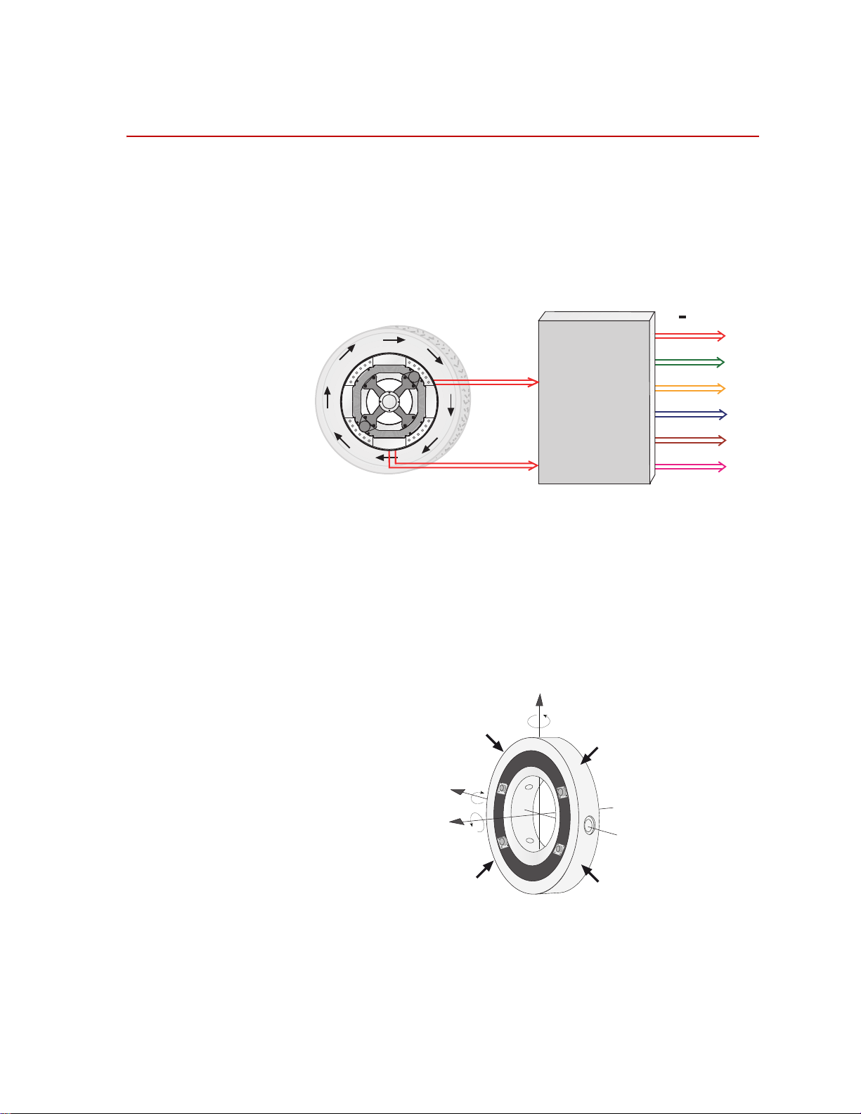
Spinning Applications (Test Track)
Spinning Applications (Test Track)
The SWIFT sensor can be used for road load data acquisition (RLDA)
applications:
• Durability
• Noise, Vibration and Harshness (NVH)
• Ride and Handling
• Tire Performance
The transducer is durable enough to withstand harsh road testing and data
acquisition environments. The transducer is splash resistant and suitable for use
in conditions where the test vehicle will encounter occasional standing or running
water, or will be exposed to precipitation. However, it should not be submerged.
In a typical spinning application, the transducer is mounted on a modified rim of
a tire on a test vehicle, as shown in the following figure. Data is transmitted from
the spinning wheel to the Transducer Interface (TI) electronics via a slip ring
mounted on the transducer.The TI, power supply, and data recorder can be
located inside the vehicle or in the trunk.
Transducer Signals
Customer Supplied
12 Vdc Power Supply
Spinning Application (Test Track)
Output
Signals
Customer Supplied
Data Recorder
Transducer Interface
(TI)
S20-26
Hardware Overview
16
SWIFT 20 Sensors
Page 17
Non-spinning Applications (Simulation Lab)
12 Vdc Power Supply
(with 4 connections)
Customer Supplied
Data Recorder
Transducer Interface
(TI)
Transducer Signals
Output
Signals
PC
Communication
S20-27
Non-spinning Applications (Simulation Lab)
The SWIFT sensor can be fully integrated into the simulation process, since it is
an optimal feedback transducer for use with MTS Remote Parameter Control
®
(RPC
) software. The transducer takes data at points where fixturing inputs are
located rather than at traditional instrumentation points along the vehicle’s
suspension. Using the SWIFT sensor saves you instrumentation time, and fewer
iterations are required to achieve good simulation accuracy.
Measuring spindle loads allows engineers to generate generic road profiles.
Generic road profiles are portable across various vehicle models, do not require
new test track load measurements for each vehicle, and eliminate additional
RLDA tasks.
Four of the six loads measured by the transducer directly correlate to the MTS
Model 329 Road Simulator inputs: vertical force, longitudinal force, lateral force,
and braking input.
The same transducers used to collect road data at the test track can be mounted
directly in the wheel adapters of the MTS Model 329 Road Simulator. For
durability testing, an aluminum SWIFT sensor can be used for iterations within
the RPC process. The aluminum SWIFT sensor should then be removed for the
durability cycles, to preserve its fatigue life. It can be replaced by an adapter
plate, available from MTS, to duplicate the mass and center of gravity of the
actual SWIFT sensor. If a SWIFT sensor is to be used during full durability tests,
we suggest using the titanium model, which has a higher fatigue rating.
®
In a typical non-spinning application, a SWIFT sensor is mounted on a road
simulation test fixture, as shown in the following figure.
Non-spinning Application (Laboratory Simulation)
SWIFT 20 Sensors Hardware Overview
17
Page 18
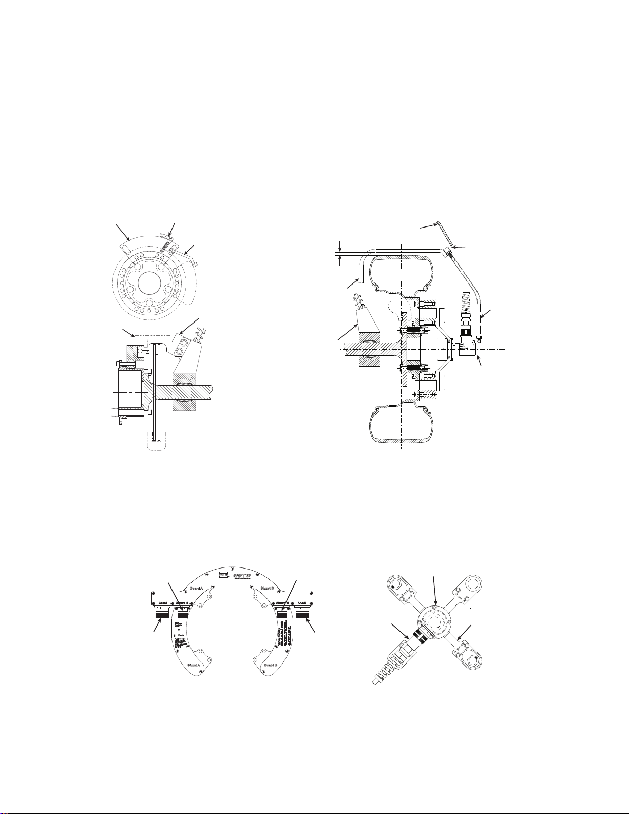
Construction
S20-57
Modified Rim
Hub Adapter
Transducer
Slip Ring
Bracket
Slip Ring
Encoder
Construction
The SWIFT sensor has one-piece construction for outstanding fatigue life, low
hysteresis, and high stiffness. Its compact package has a minimal effect on inertia
calculations, and a minimal dynamic effect on the test vehicle.
The transducer can be used for developing conventional durability tests on the
MTS Model 329 Road Simulator. Normally, the transducer is replaced with an
equivalent wheel adapter after the simulation drive signals are developed and
prior to the start of the test.
The SWIFT sensor includes several mechanical and electrical components.
Slip Ring Assembly
Transducer The transducer attaches directly to a modified wheel rim. On the test track, it
spins with the wheel. It does not spin on a road simulator. The transducer is
available in two materials: aluminum for spinning applications where the priority
is on light weight, and titanium for non-spinning or higher force applications,
where the priority is on durability.
The transducer’s unibody design means there are no multiple parts welded or
screwed together.
The transducer has four beams with strain gages that measure six orthogonal
outputs:
Fx—longitudinal force
Fy—lateral force
Fz—vertical force
Mx—overturning moment
My—acceleration and brake torque
Mz—steering moment
It has onboard conditioning and amplifiers to improve the signal-to-noise ratio.
Hardware Overview
18
SWIFT 20 Sensors
Page 19
Construction
Telemetry Model Slip Ring Model
Slip
Ring
Slip Ring
Bracket
Transducer
Interface
Cable Bracket
Anti-rotate Device
(Bend to fit vehicle)
Transducer
Customer-supplied
Attachment Bracket
Wheel Rim
Customer-supplied
Rim Adapter Flange
Attach to
vehicle
suspension
Wheel Rim
Transducer
Anti-rotate
Device
Hub
Adapter
Hub
Adapter
Brake Rotor
Telemetry Bearing
with Hub Electronics
Transducer
Interface
Cable
S20-49
Hub adapter The hub adapter attaches to the inner diameter of the transducer, allowing you to
place it at the original position of the spindle face of the vehicle. The hub adapter
enables you to maintain the original position of the tire on the vehicle while the
transducer is attached to the vehicle (the tire will not protrude from the vehicle).
Components Set Up for Test Track
Slip ring bracket The slip ring bracket is used to attach the slip ring to the transducer. It has
internal wiring that provides excitation power to the strain gage bridges and
brings signals out from the transducer to the slip ring.
Encoder An encoder measures the angular position of the transducer. The SWIFT sensor
uses an optical encoder that counts off “ticks” to measure the angular position as
the wheel rotates. In applications using a slip ring, the integral encoder measures
2048 (512 plus quadrature) points per revolution (ppr) with a resolution of 0.18
degrees and an accuracy of 0.18 degrees.
Slip ring The slip ring allows you to output the transducer bridge signals and angular
position to the TI. A transducer data cable attaches from the slip ring to the back
panel of the TI. The slip ring is not typically used for non-spinning applications.
Anti-rotate device The anti-rotate device is attached to the stator portion of the slip ring and the
SWIFT 20 Sensors Hardware Overview
vehicle’s suspension (or other non-rotating point). It is able to move up and down
with the vehicle. Its primary function is to provide a fixed reference point for the
optical encoder. Its secondary function is to prevent the cable from rotating with
the wheel and becoming tangled or breaking.
The anti-rotate device is mainly used for road data collection. Although it can
also be used for short periods of time on a road simulator. MTS does not
recommend this use. Due to the extreme fatigue loading characteristics of
durability testing on road simulators, we suggest that you either remove the slip
ring assembly before installing the vehicle on a road simulator, or use it only for
iteration passes, then promptly remove it.
19
Page 20
Construction
S20-55
Slip Ring
Assembly
Suspension/
Unsprung Mass
Tire must not
hit bracket when
loaded or rotating.
Anti-Rotate Bracket
must be stiff
(preferably steel
or stiff aluminum
tubing).
Center line
of Wheel
Anti-Rotate
Assembly
Vehicle
Fender
Bracket must not
hit fender at
extreme end of
suspension travel
Slip Ring ModelSlip Ring Model
Cable Conduit
Bracket
Alignment Fixture
Example of
Anti-Rotate
Bracket Attached
to Brake Caliper
Example of
Anti-Rotate
Bracket Attached
to Strut
Cable
Conduit
Bracket
Telemetry Model
Accelerometer
(optional)
Shunt A
Load
Shunt B
S20-54
Connector Housing
S20-58
Non-Spinning
Cable Assembly
Non-Spinning
Connector Bracket
Spinning
Slip Ring
Bracket
Non-Spinning
Connector Bracket
The slip ring anti-rotate device should be configured such that no loading occurs
to the slip ring throughout all loading and suspension travel. This means that
when you attach the anti-rotate device to the vehicle, you must consider all
possible motion of the suspension. The anti-rotate device should not bump
against the wheel well at any time; any jarring of the anti-rotate arm will damage
the slip ring. For steering axles, the anti-rotate bracket must be mounted to part of
the unsprung suspension that steers with the tire, such as the brake caliper. For
additional anti-rotate device mounting recommendations, refer to the Anti-Rotate
Customer/User Assembly drawing at the back of this manual.
Non-spinning
connector housing or
connector bracket
20
Hardware Overview
The non-spinning connector housing or the non-spinning connector bracket (both
shown below) provide a connection between the SWIFT and the TI electronics
for non-spinning use. Both assemblies incorporate rugged connectors suitable for
durability testing. The non-spinning connector housing can also include an
optional connector with built-in, tri-axial accelerometers.
SWIFT 20 Sensors
Page 21
Construction
Low-profile TI
Mini TI
Transducer Interface
(TI)
The TI comes in two versions: a Low-Profile TI and the newer Mini TI.
Information on the Low-Profile TI can be found in this manual. Information on
the Mini TI can be found in a separate product manual (MTS part number
100214316).
The Low-Profile TI conditions the power supply, and uses previously stored
calibration values to convert the eight bridge outputs and the encoder signal to
six non-rotating analog outputs (Fx, Fy, Fz, Mx, My , Mz) plus an angle output (or
angular velocity with the Mini TI). The force and moment outputs have a value
of 10 V full scale, unless a different full-scale output is requested by a customer.
The angle output is a 0–5 V sawtooth output.
Additional
components
SWIFT 20 Sensors Hardware Overview
Additional components that are supplied with your SWIFT sensor include shunt
and transducer data cables, TI power cable, a SWIFT Transducer Interface
Utilities disk, and the calibration file. MTS can also provide a 12 V DC power
converter for use in the test laboratory.
21
Page 22

Construction
Design Features
Flexure isolation The SWIFT sensor has a very stiff outer ring and flexured beam isolation which
render it relatively insensitive to stiffness variations in matings with rims and
road simulator fixtures.
Flexure isolation minimizes thermal expansion stresses. With flexure isolation, if
the inner hub experiences thermal expansion the beams are allowed to expand
out, resulting in lower compressive stress on the beams.
Thermal stability The entire sensor is machined from a solid, specially forged billet of high
strength aluminum or titanium. The absence of bolted joints permits an efficient
transfer of heat across the sensor structure, minimizing temperature differentials
in the gaged area.
As mentioned earlier, flexure isolation allows thermal expansion with minimal
stresses.
The transducer is designed to accommodate the high temperature environments
that occur during severe driving and braking events. Individual temperature
compensation of each strain gage bridge minimize temperature induced
variations in accuracy. Since minimal electronics reside on the SWIFT sensor, it
can easily tolerate high temperatures. The temperature rating for the SWIFT
sensor is 125° C (257° F) at the spindle hub.
Temperature compensation is done on each bridge for better performance in
transient or non-uniform temperature occurrences.
Low hysteresis The SWIFT sensor has very low hysteresis, since the sensing structure is
constructed with no bolted joints. Micro slippage in bolted joints contributes
most of the hysteresis in highly stressed structures. Hysteresis errors due to
micro-slip at joints can contribute to unresolvable compounding errors in
coordinate transformation of the rotating sensor.
Low noise On-board amplification of the transducer bridges minimizes noise contribution
prior to data transmission via low noise slip ring.
Low cross talk The advanced design of the SWIFT sensor means that it has very low cross talk.
The alignment of the sensing element is precision machined. This alignment is
critical to achieving minimum cross talk error between axes and minimum errors
in coordinate transformation (from a rotating to a nonrotating coordinate system).
Any small amount of cross talk present is compensated by the TI.
Velocity information Angular position output is available from the TI when it is used in the spinning
mode with the encoder. For the Low-Profile TI, this angular out put can be used to
calculate wheel velocity. In non-spinning applications, accelerometers can be
integrated into the transducer connector housing.
The Mini TI has a user selectable angle or angular velocity output.
Hardware Overview
22
Note MTS does not supply any conditioning electronics for accelerometers.
Ask your MTS consultant for more information about this option.
SWIFT 20 Sensors
Page 23
Coordinate System
Fx
Fy
Fz
Mz
Mx
My
Transducer
Interface
Output signals
+
10 Volts
Angular
Position
Bridge
Outputs
S20-06
+Mz
+Fz
+Fy
+My
+Mx
+Fx
Forces acting on outer ring
S20-07
In the transducer, independent strain gage bridges measure forces and moments
about three orthogonal axes. The signals are amplified to reduce the signal-tonoise ratio. An encoder signal indicates angular position, which is used to
convert raw force and moment data from the rotating transducer to a vehiclebased coordinate system. The force and moment and encoder information is sent
to the transducer interface (TI).
Coordinate System
The TI performs cross talk compensation and converts the rotating force and
moment data to a vehicle coordinate system. The result is six forces and moments
that are measured at the spindle: Fx, Fy, Fz, Mx, My, and Mz. A seventh (angle)
output is available for tire uniformity information, angular position, or to
determine wheel speed (depending on the data acquisition configuration).
The coordinate system shown below was originally loaded into the TI settings by
MTS. It uses the right-hand rule.
The SWIFT coordinate system is transducer-based, with the origin located at the
reference drawings at the end of this manual. Positive loads are defined as
applied to the outer ring of the transducer.
SWIFT 20 Sensors Hardware Overview
center of the transducer. The lateral offset of the transducer is illustrat ed in the
23
Page 24

Coordinate System
The direction of positive forces follows the right hand rule:
• Vertical force (Fz) is positive up
• Lateral force (Fy) is positive out of the vehicle
• Longitudinal force (Fx) is positive fore or aft of the vehicle depending on
which side of the vehicle the SWIFT is mounted
You can change to the MTS Model 329 Road Simulator convention (lateral load
into the vehicle is always positive) or to any coordinate system by changing the
polarities in the calibration file. For instructions on how to change the coordinate
system polarities, see the chapter, “Setting up the Transducer Interface” in this
manual or refer to “Transducer Interface Setup” in the Mini TI manual.
The Mini TI has the capability to offset the coordinate system. For example you
can offset the coordinate system such that the coordinate system is at the center
of the rim instead of the default coordinate system location at the center of the
transducer. The Mini TI manual has additional information.
Hardware Overview
24
SWIFT 20 Sensors
Page 25

Specifications
Specifications
SWIFT 20 Transducer Performance
Parameter Specification
Use
SWIFT 20 A (aluminum) for
SWIFT 20 T (titanium) for
Maximum usable rpm
Maximum speed
fits rim size (usable range)
Maximum hub bolt circle diameter
accommodates M12 or 1/2 inch studs
Input voltage required
Input power required per transducer
Output voltage ± full scale calibrated load
Aluminum Titanium
SAE J328 rated load capacity
Standard Maximum Calibrated Load Rating‡
Longitudinal force (Fx)
Lateral force range (Fy)
Vertical force range (Fz)
Overturning moment (Mx)
Driving/braking moment (My)
Steering moment (Mz)
Resolution (analog system)
Noise level (peak-to-peak 0-500Hz)
Performance accuracy
Nonlinearity
Hysteresis
Modulation§
Cross talk
Maximum operating temperature
Low level amplifiers
Transducer interface
* A special flange configuration is required for a 12 inch wheel. Larger diameter rims can be used, providing that overall
clearance from brake calipers and suspension components is maintained.
† Load impedance >1 k
‡ The actual calibrated range may be different based on individual customer requirements. Consult the calibration range
sheet that accompanies each transducer for the correct calibration range.
§ Typical value on most steel rims. Aluminum rims typically have slightly higher modulation, but at a lower added weight.
# Each SWIFT sensor is calibrated on an MTS calibration machine. MTS provides complete documentation of calibration
values for each SWIFT unit
#
Ω; 0.01 µF (maximum) load capacitance.
4.3 kN (965 lbf) 7.0 kN (1,580 lbf)
±21 kN (±4,720 lbf) ±30 kN (±6,745 lbf)
±16 kN (±3,595 lbf) ±25 kN (±5,620 lbf)
±21 kN (±4,720 lbf) ±30 kN (±6,745 lbf)
±4 kN•m (±35,405 lbf•in) ±6 kN•m (±53,105 lbf•in)
±5 kN•m (±44,255 lbf•in) ±8.5 kN•m (±75,230 lbf•in)
±4 kN•m (±35,405 lbf•in) ±6 kN•m (±53,105 lbf•in)
15 N (3.4 lbf) 25 N (5.6 lbf)
low weight, high sensitivity
high fatigue life, durability
2,200
240 kph (150 mph)
12–15 inch
*
4.5 inch (114.3 mm)
10–17 VDC
30 W maximum (22 W typical)
†
±10 V
Infinite
1.0% full scale
0.5% full scale
≤3.0% reading
1.5% full scale
70°C (158°F)
50°C (122°F)
SWIFT 20 Sensors Hardware Overview
25
Page 26
Specifications
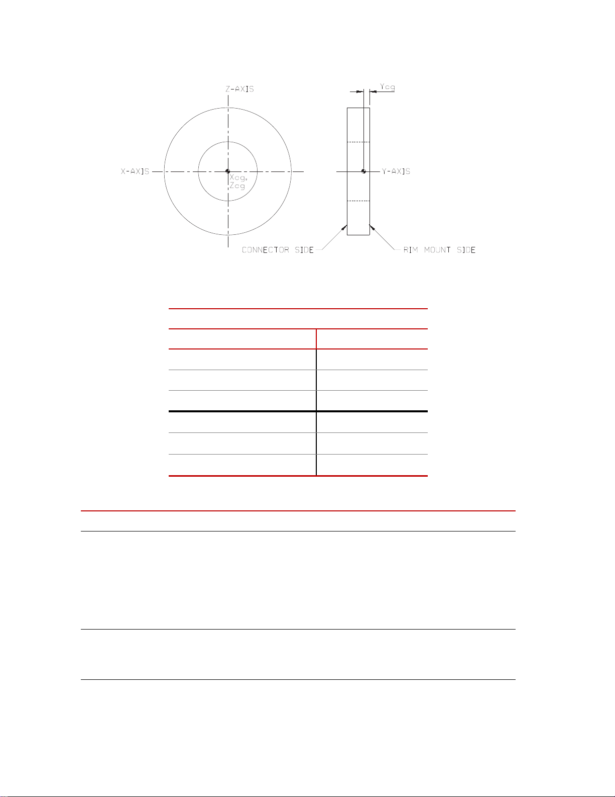
Transducer Center-of-Gravity
Transd ucer Center-of-Gravity and Inertia Specifications
Material
Aluminum Titanium
X
0.0 mm 0.000 in 0.0 mm 0.000 in
cg
Y
19.2 mm 0.755 in 19.2 mm 0.755 in
cg
Z
0.0 mm 0.000 in 0.0 mm 0.000 in
cg
I
xx
180 kg·cm262 lbm·in2290 kg·cm299 lbm·in
I
yy
353 kg·cm2121 lbm·in2569 kg·cm2195 lbm·in
I
zz
180 kg·cm262 lbm·in2290 kg·cm299 lbm·in
Low-Profile Transducer Interface (part 1 of 2)
Parameter Specification
Physical
Height
Width
Depth
Weight
Rack Mounting Kit
31.75 mm (1.25 in)
431.8 mm (17 in)
215.9 mm (8.5 in.)
1.68 kg (3 lb 11.1 oz)
Optional
2
2
2
*
Environmental
Ambient temperature
Relative humidity
Hardware Overview
26
0° C (32° F) to 50° C (122° F)
0 to 85%, non-condensing
SWIFT 20 Sensors
Page 27

Low-Profile Transducer Interface (part 2 of 2)
Parameter Specification
Power Requirements
Input voltage
Supply current
Fuse
Angular velocity
Encoder limit
Processing limit
Encoder resolution
10–17 V DC
2 A typical, 3 A maximum at 12 V DC
3 A fast-blow
2,200 rpm maximum
10,000 rpm maximum
2048 counts per revolution
(512 pulses with quadrature)
Specifications
Time delay (encoder tick to main outpu t stable)
Transducer cable length
Shunt cable length
Analog outputs
Voltage
12 µs (typical)
100 ft maximum
100 ft maximum
±10 V range† (force and moment outputs)
0–5 V sawtooth (angle output)
Capacitive load
Current
Noise at output, with typical gains
0.01 µF maximum
6 mA maximum
7 mVpp, DC - 500 Hz (typical)
15 mVpp, DC - 500 Hz (maximum)
Bandwidth (bridge input to main output)
–3 dB at 30.1 kHz (typical)
90 degree at 16.6 kHz (typical)
* Add 25.4 mm (1.0 in) for ground lugs.
† Standard from MTS. Other full scale voltages can be evaluated and may be provided at special
request.
Low-Profile Transducer Interface Communications (part 1 of 2)
Parameter Specification
Communications Channel # 1
(Remote Host Connections)
Baud rates
Parity
Stop bits
Data bits
Isolated RS-232/RS-485 interface power
supply
Electrical interface
19,200 Kbits/s
None
1
8
+5 V DC @ 200 mA maximum
Isolated RS-232 or RS-485 remote host connection
Isolated RS-485 TI to TI connection
Maximum number of devices that can be part
of a RS-485 multidrop chain
32 with RS-232 remote host
31 with RS-485 remote host
*
Maximum cable length
SWIFT 20 Sensors Hardware Overview
27
Page 28

Specifications
Low-Profile Transducer Interface Communications (part 2 of 2)
Parameter Specification
For RS-232 host:
50 ft from host to the first (nearest) TI,
and
300 ft from the first TI to the last SWIFT TI in the RS-
485 multidrop chain
For RS-485 host:
300 ft from host to the last (furthest) TI in the RS-485
multidrop chain
* Includes all compatible devices, such as an MTS 407 controller. A maximum of only nine transducer
interfaces can be connected, because the addresses are limited to 1–9.
Hardware Overview
28
SWIFT 20 Sensors
Page 29

Calibration
Calibration
Important The following sections include information related to the Low-
Profile Transducer Interface (TI). For SWIFT transducers designed
to operate with the newer Mini TI, there is a separate manual that
documents the Mini TI software utilities (MTS part number
100214316).
Each transducer is calibrated by MTS before shipment. The transducer and LowProfile TI may be returned to MTS for repair and recalibration as required.
Calibration is performed at MTS on a special fixture that is capable of applying
multiple loads to the transducer. During calibration, raw signals are measured.
The calibration gains and cross talk compensation values are computed from this
raw data. These gains are recorded in a calibration file.
A unique calibration file is supplied for each transducer. The serial number of the
Low-Profile TI associated with the transducer is listed at the top of the
calibration file. A label with the serial number of the Low-Profile TI box (and the
SWIFT sensor with which it was originally calibrated) is located at the back of
each Low-Profile TI box.
The calibration file is loaded into the Low-Profile TI non-volatile RAM by MTS
before the transducer is shipped. A copy of the file is also provided on a diskette.
MTS verifies the calibration by applying loads to the transducer, measuring the
main outputs and checking for accuracy. Final calibration reports are provided
with each transducer.
Shunt calibration At the end of the calibration process, a shunt calibration is performed. During a
shunt calibration, a resistance is introduced into the bridge circuit. The difference
between the shunted and unshunted voltage is the delta shunt reference value for
each bridge. That value is saved in the calibration file, which is downloaded from
a PC or laptop computer and stored in non-volatile memory in the Low-Profile
TI.
At any time afterward, pressing the Shunt button on the front of the Low-Profile
TI causes each of the strain gage bridges to be shunted in sequence, and the
measured shunt voltage (delta shunt measured value) is compared to the
reference value.
An acceptable tolerance range is also loaded into the Low-Profile TI memory
during system calibration. One tolerance value is used for all bridges. This value
is loaded as a percentage of allowable deviation from the delta shunt values. For
example, if the FX1 bridge has a shunt delta reference value of –3.93, and the
tolerance is set at 2 (percent), the acceptable range for the measured value would
be –3.85 to –4.01.
SWIFT 20 Sensors Hardware Overview
29
Page 30

Calibration
When you press the Shunt button, the associated Shunt LED lights. As the LowProfile TI automatically switches throug h the series of bridges, it verifies that the
outputs are within the accepted tolerance range. If all bridge shunt values fall
within the tolerance range, the Shunt LED on the front panel will go off (after
several seconds). If any bridge fails to fall within the shunt tolerance range, the
LED will blink, indicating that the shunt calibration has failed. See the chapter,
“Troubleshooting,” on page 127, for more information on dealing with shunt
calibration failures.
ShuntTolerance=2
FX1ShuntDeltaRef=-3.91836
FX2ShuntDeltaRef=-3.91896
FY1ShuntDeltaRef=-3.92366
FY2ShuntDeltaRef=-3.91639
FY3ShuntDeltaRef=-3.91824
FY4ShuntDeltaRef=-3.92494
FZ1ShuntDeltaRef=-3.92282
FZ2ShuntDeltaRef=-3.92673
FX1ShuntDeltaMeas=-3.91854
FX2ShuntDeltaMeas=-3.9192
FY1ShuntDeltaMeas=-3.92412
FY2ShuntDeltaMeas=-3.91572
FY3ShuntDeltaMeas=-3.91815
FY4ShuntDeltaMeas=-3.92464
FZ1ShuntDeltaMeas=-3.9227
FZ2ShuntDeltaMeas=-3.92646
Example of Calibration File Shunt Data
The above example shows shunt data from the calibration file. This data may be
transferred, using the TIXFER program, from the transducer interface RAM to a
computer or from a computer to the transducer interface RAM. Note that items
marked ShuntDeltaMeas are uploaded from RAM, but not downloaded from the
computer. (For more information on TIXFER, see the chapter, “Software
Utilities.”
Shunt verification You can check the electrical integrity of a transducer at any time by pressing the
Shunt switch. Subsequent shunt commands compare the current feedback values
against those stored in the Low-Profile TI. You may set the tolerance values for
each Low-Profile TI by editing the calibration file (see the chapter, “Setting up
the Transducer Interface”, for instructions).
If the current feedback values from a shunt calibration are outside the tolerance,
the Shunt LED blinks to indicate a failure.
Hardware Overview
30
SWIFT 20 Sensors
Page 31

Low-Profile Transducer Interface
Fx
Fy
Fz
Mz
Mx
My
Transducer
Interface
Output signals
(± 10 Volts)
Angular
Position
Bridge
Outputs
Transducer bridge output
signals and encoder
angular position signal are
sent through slip ring
Transducer Interface
converts signals to nonspinning vehicle coordinates,
applies calibration gains and
cross talk compensation
Force, moment, and
angle analog signals
are output from
Transducer Interface
q
Angle signal
(05 Volts)
S20-08
The Low-Profile TI performs cross talk compensation, transforms the loads from
a rotating to a non-rotating coordinate system, and produces an analog output
signal suitable for any data recorder.
Low-Profile Transducer Interface
SWIFT 20 Sensors Hardware Overview
Cross talk
compensation
Cross talk occurs when a force is applied to one axis, but a non-real force is
measured on another axis. The SWIFT sensor design has very low inherent cross
talk. The Low-Profile TI compensates for any cross talk by subtracting the nonreal forces when the amount of cross talk is known.
The amount of known cross talk is determined during the calibration process.
Cross talk values will vary slightly for different rims. For example, a steel rim
will have slightly different cross talk errors than a less rigid aluminum rim.
Signal conditioning The Low-Profile TI is specifically designed to be used for both spinning and non-
spinning applications. The Low-Profile TI performs signal conditioning and
communications functions. The output from the Low-Profile TI is a high-level
signal suitable for input into a multichannel data recorder or an MTS Automated
Site Controller (ASC).
31
Page 32

Low-Profile Transducer Interface
Fx1
Fx2
Fy1
Fy2
Fy3
Fy4
Fz1
Fz2
Fx
Fy
Fz
Mx
My
Mz
Geometric
Matrix
Zero and
Scaling
q
Cross
Coupling
Matrix
Rotational
Transformation
q
Inputs Output
s
Transducer Interface Functions
S20-09
The Low-Profile TI transforms eight inputs (amplified bridge signals) into three
forces and three moments by the following process:
• Applying a zero offset and scaling the signals
• Using a geometric matrix to transform the signals into three forces and three
moments in the transducer reference frame
• Using a cross-coupling matrix calculation to scale and sum the individual
signals into each output
• In spinning applications, using a rotational transformation to put the forces
and moments into a stationary reference frame
The Low-Profile TI conditions the transducer signals, producing seven analog
output signals proportional to the following values:
• Longitudinal force (Fx)
• Lateral force (Fy)
• Vertical force (Fz)
• Overturning moment (Mx)
• Driving/Braking moment (My)
• Steering moment (Mz)
• Angle output (θ)
Analog signals The force and moment signals are output from the Low-Profile TI in the form of
1
full scale analog signals. These signals can be used by any data
±10 V
acquisition system.
The angle output is an analog voltage that is proportional to angular position. At
0° the output is 0 V. At 360°, the output is 5 V.
32
Hardware Overview
1. Standard from MTS. Other full-scale output voltages can be evaluated and
may be provided at special request.
SWIFT 20 Sensors
Page 33

Low-Profile Transducer Interface
0 360°
5V
0° 360°
q
Angle
Output
1 rev = 360°
S20-10
The angle output for a tire rotating at constant velocity can be represented by the
following illustration:
Although you may not routinely use it, the angle output information is available
for tasks such as tire uniformity testing and troubleshooting. You may also
calculate angular velocity by measuring the frequency of the angle output signal.
Communications The Low-Profile TI provides a serial port for remote communication. The port
allows connection to an RS-232 or RS-485 host for multidrop communication.
This interface is compatible with the MTS 407 Controller protocol, and 407
Controllers may also be in the same multidrop communication chain. A
multidrop configuration can include up to 32 total devices in any combination,
with a maximum of nine Low-Profile TIs (limited to addresses 1 through 9).
The serial interface provides the following capabilities:
• allows the user to save and restore Low-Profile TI setup parameters.
• is compatible with LabVIEW®.
• is compatible with serial port-equipped computers (UNIX machines,
Macintosh, and IBM PC).
• is able to link multiple Low-Profile TIs (and 407 Controllers) to one host
computer.
SWIFT 20 Sensors Hardware Overview
33
Page 34

Low-Profile Transducer Interface
S20-11
Fuse
Power Switch
and Indicator
Shunt Switch
and Indicator
Angle Zero
Switch and Indicator
Bridge Zero
Switch and Indicator
Fail
Indicator
Transmit
Indicator
Address
Selector
Low-Profile TI Front Panel
Transducer Interface Front Panel
Fuse (F1) A 3A fuse protects the electronics.
Power switch and
Indicator
The power switch turns power on and off. A green indicator will light to indicate
that the Low-Profile TI power is turned on.
Shunt switch Pressing this switch performs a shunt calibration (shunt cal) of the transducer.
Y ou do not need to hold the switch in continuously, only until the Shunt indicator
lights up (indicating that the Low-Profile TI has started the shunt cal).
Before you perform a shunt cal, check that the appropriate shunt reference value
and error tolerance have been downloaded (these values are normally loaded
during system calibration, and are referred to as the shunt delta cal values).
A shunt calibration will determine the current delta values by measuring the
bridges unshunted and shunted, and then compare these values to the previously
loaded calibration values. If the measured values are outside of an acceptable
tolerance, the Shunt indicator will flash, indicating an error.
Shunt Indicator This indicator indicates the current state of the shunts. If there are any active
shunts, or if you are currently performing a shunt calib ration, this indicator will
be lit.
If the shunt cal check fails, this indicator flashes (at approximately a 1 Hz rate).
Note The state of the shunt cal check is cleared at power-up, so the shunt cal
should be performed when the system installation is in question.
Hardware Overview
34
SWIFT 20 Sensors
Page 35

Low-Profile Transducer Interface
[SWIFT]
Name=zero 3 after new tire
SerialNum=1234567
Normalization=0
InputSwitches=255
OutputPolarities=40
ZeroAlgorithm=4
AngleMode=0
AngleOffset=82.0898
AngleFixed=0
EncoderSize=0
ZFX1=0.103786
ZFX2=-0.023199
ZFY1=-0.094017
ZFY2=-0.184371
Angle Zero and Bridge
Zero switches
These switches are used to zero the transducer inputs. Which switch you press
depends on the ZeroAlgorithm that you specified in the calibration file (see
following illustration). Two different methods are used to zero the system:
spinning and non-spinning. For more detailed information on selecting a zero
method, see the chapter, “Setting up the Transducer Interface.”
When you select a zero method, it will activate the appropriate switch on the
Low-Profile TI front panel. Each switch performs a specific zero function:
Angle Zero– Angle offsets are required for spinning applications only. This
switch is active when the ZeroAlgorithm=1, or 3. The Low-Profile TI reads the
current angle and compensates for any offset from the Z axis facing up. You will
not use this switch for non-spinning applications.
SWIFT 20 Sensors Hardware Overview
Bridge Zero–Bridge offsets are required for both spinning and non-spinning
applications. This switch is active when the ZeroAlgorithm=0, 1, or 3. The
Low-Profile TI reads the transducer bridge values and compensates for any
offsets so that the bridge output is 0 at 0.0V.
35
Page 36

Low-Profile Transducer Interface
Angle Zero and Bridge Zero Switch Functions
Zero
When to Use Angle Zero Bridge Zero
Algorithm
0
(Preferred method
for non-spinning
applications)
1
Use this algorithm for nonspinning (fixed) applications.
Use this algorithm for
spinning applications.
You will need to
mechanically level the
SWIFT sensor.
3
Use this algorithm for
spinning applications.
You do not need to
mechanically level the
SWIFT sensor.
4
(Preferred method
for spinning
applications)
Use this algorithm for
spinning applications.
You will need to
mechanically level the
SWIFT sensor.
When a system zero is initiated, the associated LED is lit. After successful
completion of the system zero, the LED turns off. If there is a failure during the
system zero, the LED will flash at approximately a 1 Hz rate.
The Angle Zero switch is
non-functional.
Press the Bridge Zero
switch to measure and tare
out the static transducer
bridge offsets.
Press the Angle Zero switch
to read the current angle and
use the value to set the angle
sum to 0.0°.
Press the Bridge Zero
switch and rotate the
transducer to measure the
static transducer bridge
offsets.
Both the Angle Zero and Bridge Zero switches are
functional. This algorithm will perform both angle zero and
bridge zero processes based on two rotatio n s of the SWIFT
sensor regardless of which button you press.
Both the Angle Zero and Bridge Zero switches are
functional. This algorithm will perform both angle zero and
bridge zero processes from a two-point zeroing procedure.
Hardware Overview
36
SWIFT 20 Sensors
Page 37

Low-Profile Transducer Interface
Zero LEDs These indicators indicate the current state of the zero process. The
ZeroAlgorithm value (0, 1, 3, or 4) you selected in the calibration file will
determine the state of the indicators when you press either the Bridge Zero or the
Angle Zero button.
• The indicators are off under normal operating conditions
• In non-spinning applications using ZeroAlgorithm=0 (required), press the
Bridge Zero button. The Bridge Zero indicator will light for 3–4 seconds
while the Low-Profile TI is completing the bridge zero process.
• In spinning applications using ZeroAlgorithm=1 (alternate), pressing the
Bridge Zero button will light the Bridge Zero indicator continuously (no
flashing) until the wheel is spun for one revolution (index-to-index). This
may take up to two full revolutions, depending on where the encoder index
pulse starts. After one revolution of data is collected, the Bridge Zero
indicator will flash rapidly for 30 seconds while the data is analyzed and the
bridge zeroes are calculated.
• When you press the Angle Zero switch, the Angle Zero indicator will light
for a few seconds while the Low-Profile TI reads the current angle and sets
the angle offset value.
• In spinning applications using ZeroAlgorithm=3 (alternate), both the
Bridge Zero and Angle Zero indicators will light continuously until the
wheel is spun for one revolution (index-to-index). After one revolution of
data is collected, both indicators will blink rapidly for approximately two
minutes while the Low-Profile TI analyzes the data and calculates both the
angle offset and bridge zero values.
• In spinning applications using ZeroAlgorithm=4 (preferred), the Bridge
Zero and Angle Zero indicators will initially be off. After the wheel is
turned at least 1.25 turns, in order for the Low-Profile TI to locate the index,
the level can be installed and leveled. With the wheel orientated such that Fz
on the axis icon on the transducer is facing up, pressing the Bridge Zero
button will light the Bridge Zero indicator continuously for a few seconds,
then the indicator will start blinking rapidly. The Angle Zero indicator will
start blinking slowly.
• With the wheel orientated such that Fx on the axis icon on the transducer is
facing up, pressing the Angle Zero button, will light the Angle Zero
indicator continuously for a few seconds. Then both the Bridge Zero and
Angle Zero indicators will turn off.
the algorithm was unable to calculate zero, the Fail indicator will light
• If
momentarily and both the Bridge Zero and Angle Zero indicators will
blink continuously at approximately a 1 Hz rate.
• If no successful zero has been performed for the currently selected zero
algorithm, the Bridge Zero and Angle Zero indicators will flash (at
approximately a 1 Hz rate), until a zero has been initiated. Use the
TISTATUS utility for a detailed explanation of th e problem.
After successful completion of a zero algorithm, the Bridge Zero and Angle
Zero indicators turn off. Should the system zero fail, the indicators will return to
a flashing state.
SWIFT 20 Sensors Hardware Overview
37
Page 38

Low-Profile Transducer Interface
Address selector Each Low-Profile TI in a communications chain has a unique address. This
address is used in every read or write command from the host computer. The host
can transmit to only one Low-Profile TI at a time, using its assigned address. The
Low-Profile TI will reply to the host when it has received a command.
The address selector switch allows you to set the communication address for the
Low-Profile TI. When multiple TIs are connected, each must have a unique
address. The address must be 1 to 9. Address 0 is used only for broadcast
messages from the host. In the case of broadcast messages, the Low-Profile TI
does not respond to the host.
T o change an address, insert a small screwdriver in the slot and turn the dial until
the arrow points to the desired address number.
Note Make sure every Low-Profile TI on a communications chain has a unique
address. If you set two TIs on one communications chain to the same
address, you may experience unpredictable communications errors.
If two Low-Profile TIs on one communications chain have the same address,
communications to either Low-Profile TI will be unreliable. (The errors are
unpredictable, but will probably be parity or framing errors.) Assigning the same
address to two TIs does not damage the hardware.
Transmit Indicator The green Transmit indicator lights to indicate that the Low-Profile TI is
transmitting information via the COMM IN connector.
FAIL Indicator The red Fail indicator lights to indicate that a fail condition exists on the board.
Depending on the failure detected, the Fail indicator will either be on constantly
or will flash a repetitive pattern that can be used to identify the failure detected.
Certain failures are considered critical, and will result in the Low-Profile TI
becoming completely unusable. These failure conditions must be resolved before
the Low-Profile TI can be used. If a critical failure occurs, the Fail indicator will
only blink the cause of the first critical failure. This failure code will be repeated
approximately every 1 second.
Non-critical failures indicate impaired system functionality, which, in most
cases, can be corrected operationally from the communication interface. Noncritical failure codes are checked cyclically, so that multiple failure conditi ons
can be communicated. Failure codes are indicated approximately every 1.5
seconds.
The following table lists fail conditions and the manner in which the Fail
indicator indicates the failure.
Error Codes for the Fail Indicator (part 1 of 3)
Fail Indicator State
[Number of blinks:]
Error
Off
Continuous On
Fast blinking
Fast varying blink
1
Hardware Overview
38
No error detected
Critical: Boot failure; bad code in boot block
Critical: Unanticipated exception prior to relocation of loader code
Critical: Unanticipated exception after relocation of loader code
Critical: SRAM failure
SWIFT 20 Sensors
Page 39

Fail Indicator State
[Number of blinks:]
2
Low-Profile Transducer Interface
Error Codes for the Fail Indicator (part 2 of 3)
Error
Critical: Local register failure
3
5
6
7
8
9
10
11
Critical: Boot block CRC failure
NVRAM error. An error was detected during the NVRAM self-test. This
self-test is performed at every power-cycle, and verifies that the NVRAM
checksum is valid, and also that the data stored is compatible with the
current firmware version. A failure of this test will require an NVRAM Init
command to be issued. Issuing this command will result in all stored
settings being cleared.
Self-T est fail. A failure was detected during the commanded self-test (note
that this is different than the power-up self-test). Further information can
be obtained by reading the self-test error status.
Operational error. These errors are usually caused by issuing
communication commands with invalid Command IDs, out-of-range data,
invalid slot number, and so on. This error condition is cleared after the Fail
indicator has indicated it.
Serial EEPROM Error. A checksum or version error was detected on the
serial EEPROM data. This data stores normalization values.
AD Failure. An error (gain out of range or off set ou t of r ange) o ccurred o n
at least one A/D, when the A/D gains and offsets were set. The ability to
perform a zero, self-test or shunt tests may be impaired in this state.
Issuing a Cal A/D command may clear this state.
Critical: Memory allocation failur e
Critical: An unexpected interrupt occurred.
12
13
14
15
16
17
Communication Interface Init Error. An error occurred while attempting to
initialize the communication interface. The communication interface may
be unusable in this state.
Low-Profile TI Firmware Init Error . An error occurred while attempting to
initialize the Low-Profile TI firmware. The communication interface may
be unusable in this state.
Box ID Error. An error occurred while attempting to initialize the LowProfile TI Box ID. The communication interface may be unusable in this
state.
DAC Init Error. An error occurred while attempting to initialize the LowProfile TI DACs. The functionality of the Low-Profile TI may be impaired
in this state.
Switch Init Error. An error occurred while attempting to initialize the LowProfile TI switches. The functionality of the Low-Profile TI may be
impaired in this state.
Encoder Init Error. An error occurred while attempting to initialize the
Low-Profile TI encoder interface. The functionality of the Low-Profile TI
may be impaired in this state.
SWIFT 20 Sensors Hardware Overview
39
Page 40

Low-Profile Transducer Interface
Error Codes for the Fail Indicator (part 3 of 3)
Fail Indicator State
[Number of blinks:]
18
Error
AD Init Error. An error occurred while attempting to initialize the LowProfile TI A/Ds. The ability to perform a self-test, and/or shunt tests may
be impaired in this state.
19
Shunt interface Init error. An error while attempting to initialize the shunt
interface. The shunt interface may be unusable in this state.
Hardware Overview
40
SWIFT 20 Sensors
Page 41

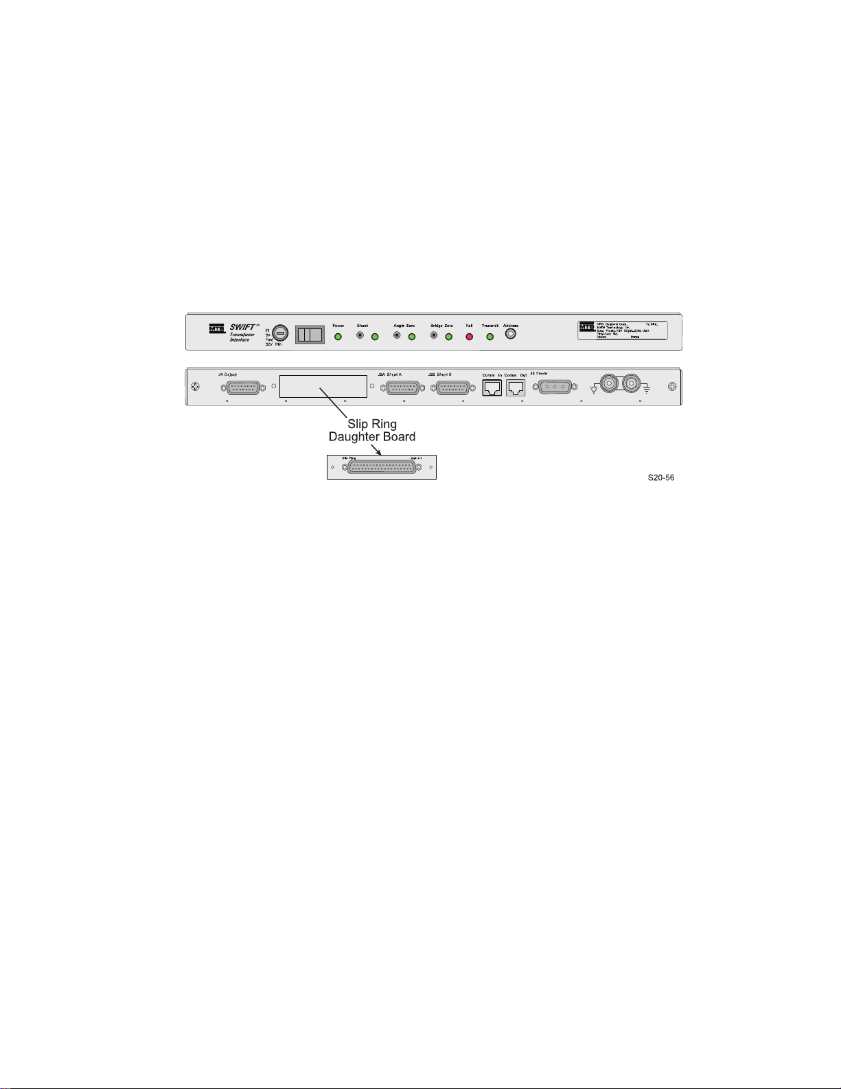
Low-Profile TI Rear Panel
J2A Shunt A
and J2B Shunt B
J4 Output
Comm In and
Comm Out
J3 Power
Ground
Terminals
S20-31
Transducer
Connector
Slip Ring
Daughter Board
Telemetry
Daughter Board
or
Data
Connector
Encoder
Output Connector
Indicators
Error/Low Power/Ready
Low-Profile Transducer Interface Rear Panel
Low-Profile Transducer Interface
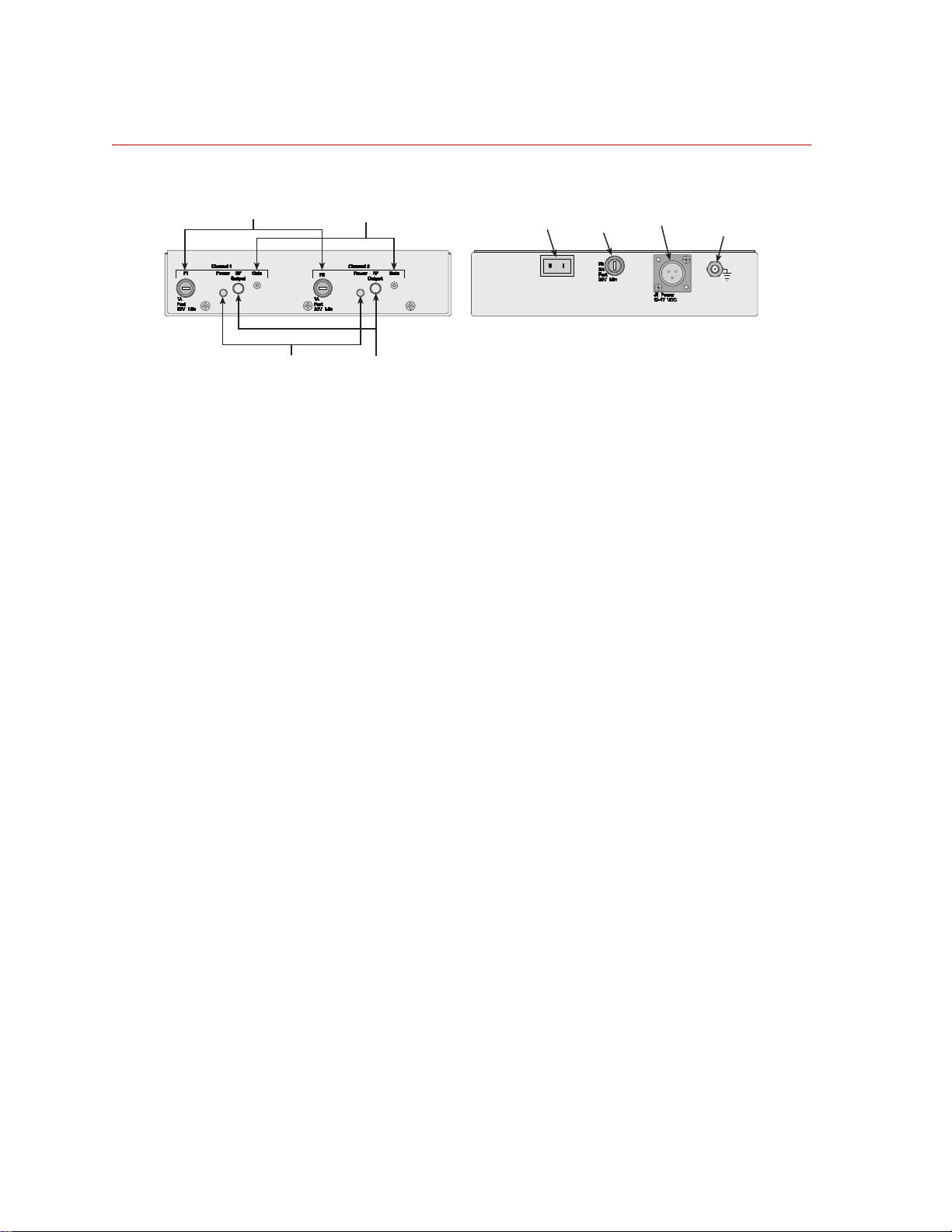
J4 Output connector The J4 Output connector provides the conditioned sensor outputs that can be
connected to a data acquisition or test control system.
J2A Shunt A
J2B Shunt B
The J2 connectors are used for the shunt cables. The shunt cables are connected
to the two 6-pin shunt cal connectors on the front of the transducer.
connectors
Comm In Comm In is an 8-pin modular phone jack connector (RJ-45) that provides a
connection to an RS-232/RS-485 remote host, or to another Low-Profile TI in an
RS-485 multidrop communications chain. The cable connected to Comm In
selects an RS-232 or RS-485 interface. The RS-232/RS-485 interfaces on Comm
In are electrically isolated from the Low-Profile TI power. This connection is
only needed when you are downloading new settings to the Low-Profile TI
module.
Under normal operating conditions, no host connection is required. The Comm
In and Comm Out connectors allow you to daisy-chain multiple boxes without
Y cables or multiple connections to the host computer.
Comm Out Comm Out is an 8-pin modular phone jack connector (RJ-45) that provides a
connection to another Low-Profile TI chassis in an RS-485 multidrop
communication chain.
J3 Power connector Connect a power cable from an external 12 V DC source.
Ground Terminals The ground terminals enable you to ground the Low-Profile TI, and chain several
Low-Profile TI boxes together.
Slip ring daughter
board
A slip ring daughter board must be installed in the Low-Profile TI when a
SWIFT transducer with a slip ring will be mounted on the vehicle
Transducer connector Connect the data cable from the transducer slip ring to the Transducer Connector.
SWIFT 20 Sensors Hardware Overview
41
Page 42
Low-Profile Transducer Interface
Power
Switch
Fuse (F3)
J1 Power
Ground
Terminal
Fuses (F1, F2)
Power
Indicator
RF Output
Connector
Gain
(trim pot)
S20-32
Front
Rear
Induction Power Source
Fuses (F1, F2) Provides circuit protection for up to two systems.
Induction Power Source
Power indicator Indicates (green) when power is available to the induction power source.
RF output connector Provides power for up to two system.
Gain (trim pot) Allows you to adjust the power gain if the LPwr indicator on the daughter board
if the Low-Profile TI is blinking, indicating the power available to the system is
marginal.
Power switch Controls power to the induction power source.
Fuse (F3) Provides circuit protection for the induction power source.
J1 Power Connects the induction power source to an external 12 V DC source.
Ground terminal The ground terminal enables you to ground the induction power source.
42
Hardware Overview
SWIFT 20 Sensors
Page 43

Low-Profile TI Jumpers
X2
X1
X4
X5
X6
S20-13
The transducer interface uses circuit board jumpers to establish certain
parameters and make use of various electronic functions. These jumpers are set at
the factory, and should not be reset. Th e followi ng table is for reference only.
Jumper Setting Function
Low-Profile Transducer Interface
X1
1–2
2–3
X2
1–2
2–3
X4 removed
X5 installed
removed
X6 installed
removed
Excitation setup for shunts FX1, FY1, FY4, and FZ2.
Sets up – (minus) excitation for shunts FX1, FY1, FY4, and FZ2.
Sets up + (plus) excitation for shunts FX1, FY1, FY4, and FZ2.
Excitation setup for shunts FX2, FY2, FY43 and FZ1.
Sets up – (minus) excitation for shunts FX2, FY2, FY43 and FZ1.
Sets up + (plus) excitation for shunts FX2, FY2, FY43 and FZ1.
Not used for Low-Profile TI applications (Standard setting).
Enables the ability to download new code to the block of FLASH RAM
where the boot code is stored.
Disables the ability to download new code to the block of FLASH RAM
where the boot code is stored (Standard setting).
Boots to the FLASH memory down-loader.
Boots to the Transducer Interface software (Standard setting).
Low-Profile TI PWB Jumper Locations
SWIFT 20 Sensors Hardware Overview
43
Page 44

Interfacing with RPC
Interfacing with RPC
The SWIFT sensor is directly compatible with the MTS Remote Parameter
Control (RPC) simulation software. The SWIFT system produces outputs that
directly correspond to the uncoupled spindle forces that the MTS Model 329
Road Simulator applies to the vehicle. Traditional instrumentation techniques
provide coupled suspension loads data. Using the SWIFT sensor, the RPC
simulation software needs to apply less correction to obtain the road simulator
drive signals. Fewer iterations are required to recreate the measured loads.
You must ensure that the full scale value for your data recorder and the MTS
Series 498 electronics match. MTS electronics are typically set at ±10 V full
scale, while some data recorders are ±5 V full scale.
The SWIFT sensor is calibrated for ±10 V full scale. To recompute the LowProfile TI gains for ±5 V full scale, a verification pass must be run or the
calibration will not be traceable. Upon special request, MTS can evaluate and
may provide calibration for ±5 V or other full scale voltages.
Hardware Overview
44
SWIFT 20 Sensors
Page 45

Software Utilities
Important This section includes information related to the Low-Profile
Contents Introduction 46
TISTATUS - Low-Profile Transducer Interface Status 47
TIXFER - Low-Profile Transducer Interface Transfer 48
TISHUNT - Low-Profile Transducer Interface Shunt 51
TISETZERO – Low-Profile Transducer Interface Set Zero Method 56
Error Messages 57
Shunt Error Status 58
Transducer Interface (TI). Fo r SWIFT transducers designed to
operate with the newer Mini TI, there is a separate manual that
documents the Mini TI software utilities (MTS part number
100214316).
SWIFT 20 Sensors Software Utilities
45
Page 46

Introduction
Introduction
The SWIFT utility programs in this distribution are for Win32 Operating
Systems (Windows 95, 98, NT, 2000, XP). They are designed to be run from the
Command Prompt or MSDOS Shell. However, it is possible to create a shortcut
to run the programs. If launched from a shortcut the application window may
close immediately when the application terminates making it impossible to see
any error messages. The Command Prompt application is usually found in
Start–>Programs–>Accessories but the actual location depends on the version
of your operating system.
To run a SWIFT utility program
• Copy it to your computer. For example, create the folder
the executables (*.exe) to that folder.
• Launch Command Prompt
• Change the working directory to where you copied the executables: cd bin.
This step can be eliminated if you set up the PATH environment variable to
include the directory where you copied the SWIFT utility executables.
• Type the name of a SWIFT utility program providing the necessary
command line arguments:
provided the program will display a simple help message. This is helpful if
you forget the order of the command line arguments.
In the Windows environment the SWIFT utilities programs define port 1 as
COM1: and port 2 as COM2:. Which communications port you specify depends
on which connector on the computer the serial communications cable is plugged
into. T o confuse things, some computers label the communications connectors as
“A” and “B”.
1
tixfer 1. If no command line arguments are
C:\bin and drag
2
Software Utilities
46
1. You may want to change the layout properties for the Command Prompt
window to display a larger area or to increase the screen buffer size. Within
Command Prompt, select Properties and the Layout tab to modify the
screen buffer size or window size.
2. In Windows 2000 the environment variables can be changed at
Start–>Control Panels–>Systems. Click on the Advanced tab, and the
Environment Variables… button. The path is a system variable. Adding
;c:\bin, or whatever directory name you used, to the end of the string will
cause Command Prompt to search that directory for applications.
SWIFT 20 Sensors
Page 47

TISTATUS - Low-Profile Transducer Interface Status
TISTATUS - Low-Profile Transducer Interface Status
This program is used to get status information from the SWIFT Low-Profile
Transducer Interface (TI). When the Low-Profile TI has encountered a problem
and is blinking an error code, this program can be used to easily interpret the
error. For certain errors this program may provide additional information. The
program also provides information such as the internal power supply voltages.
Note The power supply voltages displayed may be unreliable if the power
supplies are too low, as the circuit used to measure the power supply
also depends on the available power.
Syntax The tistatus command requires two arguments:
tistatus port box
port is the communications serial port number
1 = COM1:
2 = COM2:
box is the Low-Profile TI communications address
1 = lowest possible address
9 = highest possible address
Example
C:\bin>tistatus 1 1
tistatus $Revision: 1.6 $ ($Date: 2002/04/10 21:05:49 $)
Reads status from the SWIFT Transducer Interface
Requires that the remote comm port be configured for 19200 baud, 8 data bits, no parity, 1 stop
bit.
Tue Dec 28 10:15:14 2004
Firmware Version: 2.6.1
Ground = 0
+5V Supply = 4.98904
+15V Supply = 14.9479
-15V Supply = -14.9433
+5V Ref = 5.00092
-5V Ref = -5.00763
No system errors to report
Closing the communications port...
Program completed.
SWIFT 20 Sensors Software Utilities
47
Page 48

TIXFER - Low-Profile Transducer Interface Transfer
TIXFER - Low-Profile Transducer Interface Transfer
This program is used to change settings within the SWIFT Low Profile
Transducer Interface (TI). It can be used to read the current settings and save
them to the computer (upload) or write the settings to a Low-Profile TI with
values from a file on the computer (download).
Syntax The tixfer command requires one argument:
tixfer port
port is the serial port number
1 = COM1:
2 = COM2:
Example
C:\bin>tixfer 1
tixfer $Revision: 1.11 $ ($Date: 1999/04/21 10:12:40 $)
0...exit
1...Upload/Save a chassis
2...Restore/Download a chassis
Enter choice? 1
Enter TI box address? 1
Enter output specifications filename? example.cal
Enter description? example for uploading settings
Allocating box...
Initializing box...
File Format The file used with commands contains a header and a list of parameters.
Transducer calibrations can be uploaded and saved individually. If a test needs to
be rerun at a later date but the original transducer is not available, another
transducer can be used by downloading its calibration information.
The header must be the first thing in the file, and it must be in the form:
[SWIFT]
Following the header is a list of parameter settings. The syntax is:
ParamName=ParamValue
Software Utilities
48
SWIFT 20 Sensors
Page 49

TIXFER - Low-Profile Transducer Interface Transfer
CAUTION
CAUTION
The following rules apply:
Tabs and spaces are allowed.
The parameters can occur in any order
Names are case insensitive. If a parameter name is not recognized, an error
will be reported, and further processing will be stopped.
If an error causes the program to abort while downloading, any parameters
prior to the error will have been successfully downloaded because
parameters are downloaded as they are read.
Make important files read-only after uploading. After uploading important
files, such as those containing calibration data, make them read-only.
If not protected, important data may get overwritten.
Make important files read-only, and make backups of important data.
More about TIXFER
files
Check force and moment output signals after downloading new settings.
Downloading new settings may affect Transducer Interface outputs.
After downloading new settings, force and moment output signals should be
monitored to check basic system operation.
The files created by TIXFER are plain text files that can be read by Microsoft
Notepad or WordPad. In general, use a common extension such as “.cal” to help
identify the files, but that is not required. The settings files contain both
configuration settings and calibration settings. As a general rule parameters that
begin with K are calibration gains and should not be edited. Configuration
settings such as the zero algorithm can be changed without affecting the
calibration.
Whenever downloading settings, make sure the file is for the transducer
connected to the SWIFT Transducer Interface. Usually the filename for the
settings contains the serial number for the transducer. If settings for one
transducer are used with another they will not be accurate. Because the LowProfile TI is calibrated by itself, calibration settings for a given transducer can be
used with any Low-Profile TI, however, some calibration methodologies require
the transducer, cable and Low-Profile TI to be used as a calibration set (end-toend calibration).
The serial number in the TIXFER settings file is the serial number of the LowProfile TI that the settings were first uploaded from.
SWIFT 20 Sensors Software Utilities
49
Page 50

TIXFER - Low-Profile Transducer Interface Transfer
The bridge and angle zero values will change whenever a zero is activated by
pressing the Low-Profile TI front panel zero button. Therefore, after a zero is
performed the zero values uploaded will not match those downloaded.
All parameters within the Low-Profile TI have been calibrated. Because the
resolution of each adjustable parameter is finite, downloaded values may vary
slightly from subsequent uploads and the values uploaded from various units may
be different. The downloaded value gets “snapped” to the closest realizable
value. The realizable values depend on the resolution and calibration data for the
parameter. Normally the gains from the SWIFT automated calibration stand are
computed to a higher resolution than the Low-Profile TI is capable of dealing
with.
Software Utilities
50
SWIFT 20 Sensors
Page 51

TISHUNT - Low-Profile Transducer Interface Shunt
TISHUNT - Low-Profile Transducer Interface Shunt
This program is a utility with various functions related to shunts. The SWIFT
system includes the ability to connect a shunt resistor across each of the resistive
bridges in the transducer. This shunt function can be used as a simple verification
that the SWIFT system is working normally. Shunt verification activates the
shunts and compares the results to those recorded during calibration. While this
does not guarantee the transducer is still in calibration, it provides some level of
confidence it is working normally. If the shunt results differ significantly from
those recorded during calibration the SWIFT system should be evaluated for
possible problems.
Syntax The tishunt command requires one argument, as follows:
tishunt port box
port is the communications
1 = COM1:
2 = COM2:
box is the SWIFT-Low-Profile TI communications address
1 = lowest possible address
9 = highest possible address
Example
Initializing box...SWIFT TI Shunt Main Menu
0...exit
1...Read current Shunt values
2...Set the TI shunt tolerance
3...Restore Shunt parameters from a file
4...Scan inputs & outputs with shunts
5...Command a shunt cal
6...Write last shunt measurements to a parameter file
Enter choice:
The Shunt Main Menu options are described in the following paragraphs.
SWIFT 20 Sensors Software Utilities
51
Page 52

TISHUNT - Low-Profile Transducer Interface Shunt
Option 0 Use this option to exit the program.
Option 1 Use this option to read the shunt tolerance, the last measured shunt values, the
reference values, and the shunt error status.
Note The shunt error status is not maintained over power cycles, so it is only
valid if the shunt is executed after power is applied. Refer to, “Shunt Error
Status,” on pag e 58 for additional information about shunt error status.
This option asks if you want to save the data in a file. Answer Y or N, and if Y,
then supply the file name when prompted. The following is typical of what is
displayed when this selection is made:
Reading Shunt parameters from TI... OK
Shunt Delta Tol: 10.000%
FX1 Ref: 3.935 Measured: 3.934 Error Status: 0
FX2 Ref: 3.932 Measured: 3.932 Error Status: 0
FY1 Ref: 3.937 Measured: 3.930 Error Status: 0
FY2 Ref: 3.929 Measured: 3.930 Error Status: 0
FY3 Ref: 3.932 Measured: 3.932 Error Status: 0
FY4 Ref: 3.931 Measured: 3.932 Error Status: 0
FZ1 Ref: 3.930 Measured: 3.935 Error Status: 0
FZ2 Ref: 3.932 Measured: 3.934 Error Status: 0
Save to a file (y/n)?
Note If you save to a file, the file is created in the same directory as the tishunt
program. The file name must contain less than 80 characters.
Option 2 Use this to set the shunt tolerance. When selected, the following is displayed:
The Shunt Tolerance specifies how much the measured shunt deltas may deviate
from the Ref settings, and still be considered good.
The value is entered as a percentage, where "1.0" would mean 1.0% of the Ref
settings.
For example: if the tolerance is 1%, and the Ref setting is 8.0, then the
measured delta must be between 7.92 and 8.08 to be considered good.
It is not necessary to reboot the TI when this value is changed, but a Shunt
Calibration must be executed to update the Shunt Error Status words.
Also note that a parameter download will overwrite this value.
Enter tolerance (in percent):
Software Utilities
52
SWIFT 20 Sensors
Page 53

TISHUNT - Low-Profile Transducer Interface Shunt
Option 3 Use this option to restore shunt settings from a file. The file format is the same as
that used in the tixfer program.
Option 4 Use this option to apply a shunt sequentially, reading the eight bridges and six
outputs of the Transducer Interface. Note that this option does not update the
shunt measured values or error status. A reading is first made with no shunts
applied (displayed as the zeroes data). The remainder of the readings are
displayed as delta values from the original readings.
Enter Filename to save data to (the file will be appended):
Enter Description:
Reading bridges & outputs unshunted
FX1
FX
zeroes:
bridges: 0.000 0.002 0.000 0.000 0.001 0.000 0.001 0.000
outputs: -0.003 -0.006 0.001 0.000 -0.002 0.000
deltas:
Shunting FX1
bridges: -3.933 0.000 -0.001 0.002 -0.001 0.001 0.000 0.000
outputs: -9.014 0.031 -0.031 -0.001 -3.246 -0.188
Shunting FX2
bridges: -0.002 -3.929 0.000 0.001 0.000 0.001 0.001 0.001
outputs: -9.198 -0.049 0.026 -0.011 3.259 -0.072
Shunting FY1
bridges: -0.001 0.001 -3.931 0.001 -0.001 0.000 -0.001 0.001
outputs: 0.029 -8.493 -0.145 -3.695 0.024 0.002
Shunting FY2
bridges: 0.000 -0.001 -0.001 -3.930 0.000 0.000 0.000 0.001
outputs: 0.175 -8.322 0.031 0.021 -0.014 -3.647
Shunting FY3
bridges: -0.001 0.001 -0.001 0.000 -3.931 0.001 0.000 -0.001
outputs: 0.005 -8.538 0.163 3.692 -0.016 -0.003
Shunting FY4
bridges: -0.002 0.001 0.000 0.000 0.001 -3.932 -0.001 0.000
outputs: -0.150 -8.271 -0.018 -0.021 0.021 3.712
Shunting FZ1
bridges: 0.000 0.001 0.000 0.000 -0.001 0.002 -3.922 -0.001
outputs: 0.105 -0.010 -7.482 0.129 -2.892 -0.052
Shunting FZ2
bridges: 0.000 -0.001 0.000 0.001 0.000 0.001 -0.001 -3.931
outputs: -0.052 -0.081 -7.021 0.114 2.749 0.049
FX2
FY
FY1
FZ
FY2
MX
FY3
MY
FY4
MZ
FZ1 FZ2
SWIFT 20 Sensors Software Utilities
53
Page 54

TISHUNT - Low-Profile Transducer Interface Shunt
Option 5 Use this option to command a Shunt Cal in the Transducer Interface. This is the
same as pressing the Shunt button on the front panel of the Low-Profile TI. A
period is displayed on the screen for every change in the shunt state. This gives
you a quick view of the progress.
TI Shunt Cal state 2
TI Shunt Cal state 5
TI Shunt Cal state 7
TI Shunt Cal state 8
TI Shunt Cal state 11
TI Shunt Cal state 14
TI Shunt Cal state 17
TI Shunt Cal state 20
TI Shunt Cal state 23
TI Shunt Cal state 26
TI Shunt Cal state 29
TI Shunt Cal state 32
TI Shunt Cal state 34
TI Shunt Cal state 35
TI Shunt Cal state 38
TI Shunt Cal state 41
TI Shunt Cal state 43
TI Shunt Cal state 44
TI Shunt Cal state 47
TI Shunt Cal state 0
TI Shunt Cal completed.
Read results by selecting appropriate menu option.
Option 6 A valid shunt calibration should be performed prior to executing this command.
This option allows an easy means of setting the Shunt Calibration Reference
values after calibration. After this option has executed, the file that was written
can then be downloaded (using option 3). Downloading the file will set the Shunt
Reference values to the last measured values, so that subsequent Shunt
Calibrations should pass when the SWIFT system is setup properly, and fail
when not setup properly.
Note This menu choice should only be used by qualified service personnel.
Software Utilities
54
SWIFT 20 Sensors
Page 55

TISHUNT - Low-Profile Transducer Interface Shunt
Setting Up Shunt Calibration Reference Values
The tishunt utility provides all of the necessary functions for setting up a
Transducer Interface with valid Shunt Cal Reference values.
Note This procedure should only be performed by qualified service personnel.
Before running the tishunt utility, connect the Transducer cable and Shunt cables
from the SWIFT Low-Profile TI to the SWIFT Transducer Assembly. Power up
the SWFT Low-Profile TI and wait for the red Fail indicator on the Low-Profile
TI front panel to go out (this indicates that the Low-Profile TI is ready).
Note that it is not necessary to perform a System (Transducer) Zero prior to the
Shunt Cal.
Procedure 1. Launch the tishunt utility.
2. Using Option 2, enter the desired shunt tolerance.
3. Using Option 5, command a shunt cal, and wait for it to complete. This
causes the Low-Profile TI to apply and measure each shunt delta. These
measured values will be written as the Cal Reference values. The Shunt
indicator on the Low-Profile TI front panel should not blink (blinking
indicates that the shunt cal verification failed).
4. Using Option 1, read the current shunt parameters. It is not necessary to save
these to a file. Review the measured values and verify that they are correct.
5. Using Option 6, write the last shunt measurements to a parameter file. This
sets up a file that contains the eight Set Shunt Cal Reference commands,
with the last measured values as the values for the commands. This step
does not download the values, but forces the generation of a shunt cal
reference parameter file.
Write down the filename that is generated, as it will be required later.
6. Using Option 3, restore shunt parameters from a file. Enter the filename
used in Option 6 (Step 5). The tishunt utility then downloads the shunt cal
reference values to the Low-Profile TI. These values are written into nonvolatile memory within the Low-Profile TI, and are automatically restored
whenever the Low-Profile TI is powered up.
7. Using Option 5, command another shunt cal, and wait for it to complete.
This provides a verification, showing that the values downloaded are valid.
The Shunt indicator on the Low-Profile TI Front Panel should not blink
(blinking indicates that the shunt cal verification failed).
SWIFT 20 Sensors Software Utilities
55
Page 56

TISETZERO – Low-Profile Transducer Interface Set
TISETZERO – Low-Profile Transducer Interface Set Zero Method
This program allows some configuration settings to be changed in a SWIFT
Low-Profile Transducer Interface (TI) without modifying a settings file. This
program only changes configuration settings, it does not change any calibration
settings.
Syntax :
tisetzero port box [zero_algo]
port is the communications
1 = COM1:
2 = COM2:
box is the Low-Profile TI communications address
1 = lowest possible address
9 = highest possible address
zero_algo is optional and specifies the zero algorithm
0 = lowest
4 = highest
Example
C:\bin>tisetzero 1 1
Firmware Version: 2.6.1
Current angle mode is ENCODER
Current zero algorithm is SPINNING BRIDGE AND ANGLE UNLOADED
Zero algorithms...
0) exit
1) fixed
2) spinning bridge
3) spinning bridge and angle unloaded
4) spinning 2 point
Enter choice?
Option 0
Use this option to exit the program
Option 1 Use this option for fixed (non-spinning) applications. It sets the AngleMode to 1
(fixed) and the ZeroAlgorithm to 0 (fixed). You may need to set the fixed angle
manually.
Software Utilities
56
Option 2 Use this option for spinning applications. It sets the AngleMode to 0 (encoder)
and the ZeroAlgorithm to 1 (spinning bridge, angle with level).
Option 3 Use this option for spinning applications. It sets the AngleMode to 0 (encoder)
and the ZeroAlgorithm to 3 (spinning bridge and angle)
Option 4 Use this option for spinning applications. It sets the AngleMode to 0 (encoder)
and the ZeroAlgorithm to 4 (2-point bridge and angle with level).
SWIFT 20 Sensors
Page 57

Error Messages
When a SWIFT utility encounters an error, a traceback message is displayed. An
example traceback message is:
serial port command timeout, received: 0 chars, buffer:
-1: (DoTIUploadBox) upload box error
-1: (SwiftTI::Init) error reading typeid
-1: (MParm::ReadVal) error read value for Type ID
-1: (MPort::DoCommand) error sending or receiving response
-4: (MPort::GetResponse) error parsing error code
-4: (ParseErrorCode) expected @
Usually you only need to be concerned with the first line of the traceback which
gives a summary of the error. The indented list of messages may provide
additional information that in some instances will be helpful to determine the
cause of an error. For instance, if the program reported an “out of range” error
one of the other lines may indicate the name of the parameter being written to
when the error occurred.
Error Messages
The number at the beginning of an indented error line is an error number.
Negative error numbers are generated by the SWIFT utility program. Positive
error numbers are generated by the Low-Profile TI.
SWIFT 20 Sensors Software Utilities
57
Page 58

Shunt Error Status
Shunt Error Status
This is the error status for each bridge from the last shunt cal that was performed.
The error status is a bit-mapped status word, where the error is present if the bit is
set to 1.
Bit 0 = Bridge amplifier was saturated prior to applying the shunt.
Bit 1 = Bridge amplifier was saturated after applying the shunt.
Bit 2 = Measured delta value failed high.
Bit 3 = Measured delta value failed low.
Bit 4 = A procedural error occurred (unable to read a value, etc.).
In the following example the error status received is 5 indicating that bits 0 and 2
were set.
Bit 43210
Bit Value168421
Example00101
Error Status=
5
Software Utilities
58
SWIFT 20 Sensors
Page 59

Setting up the Low-Profile Transducer Interface
Important This section includes information related to the Low-Profile
Transducer Interface (TI). Fo r SWIFT transducers designed to
operate with the newer Mini TI, there is a separate manual that
documents the Mini TI setup (MTS part number 100214316).
Overview Three different software configurations are used by the TI, depending on whether
you will be using the SWIFT sensor on the test track (spinning application) or in
the laboratory (non-spinning application). Angular transformation is required on
the test track only. If you are using angular transformation, you must define the
encoder resolution. If you are using the same transducer and TI for data
collection and simulation testing, you must change the software configuration
before the TI can be used for simulation testing.
Contents Select a Zero Method 60
Calibration File Elements 61
Zero Algorithms 62
Upload the Calibration File 64
Edit the Calibration File 66
Download the Calibration File 70
SWIFT 20 Sensors Setting up the Low-Profile Transducer Interface
59
Page 60

Select a Zero Method
Select a Zero Method
Before you install a transducer and zero it, you must configure the transducer
interface (TI) for the appropriate zero method.
Equipment required You will need:
• A laptop computer (at test track) or desktop PC
• Serial port communication cable
• SWIFT Transducer Interface Utilities diskette
• Know the address assigned to each TI box
• Some experience with DOS commands and text editors
Zero methods There are two separate zero algorithm classes used to zero the transducer inputs.
The method you choose depends on whether you will use the transducer in a
spinning (test track) application (Zero Algorithm 1, 3 or 4) or non-spinning (road
simulator) application (Zero Algorithm 0).
If you are using the same transducer with a road simulator that you used
previously on the test track, you must re-zero the transducer using the nonspinning zero algorithm.
When you select an algorithm, you are also enabling the zero button(s) on the
front panel of the TI. There are two zero buttons:
Bridge Zero
Angle Zero
What you need to do To change the zero algorithm used by the TI you will need to:
1. Copy the original calibration file from the diskette that came with the
transducer to the computer.
2. Edit the calibration file to select a zero algorithm and angle mode.
3. Download the modified calibration file from the computer to the TI box.
4. Repeat the process for all of the transducers.
These steps are described in detail in the following sections.
Setting up the Low-Profile Transducer Interface
60
SWIFT 20 Sensors
Page 61
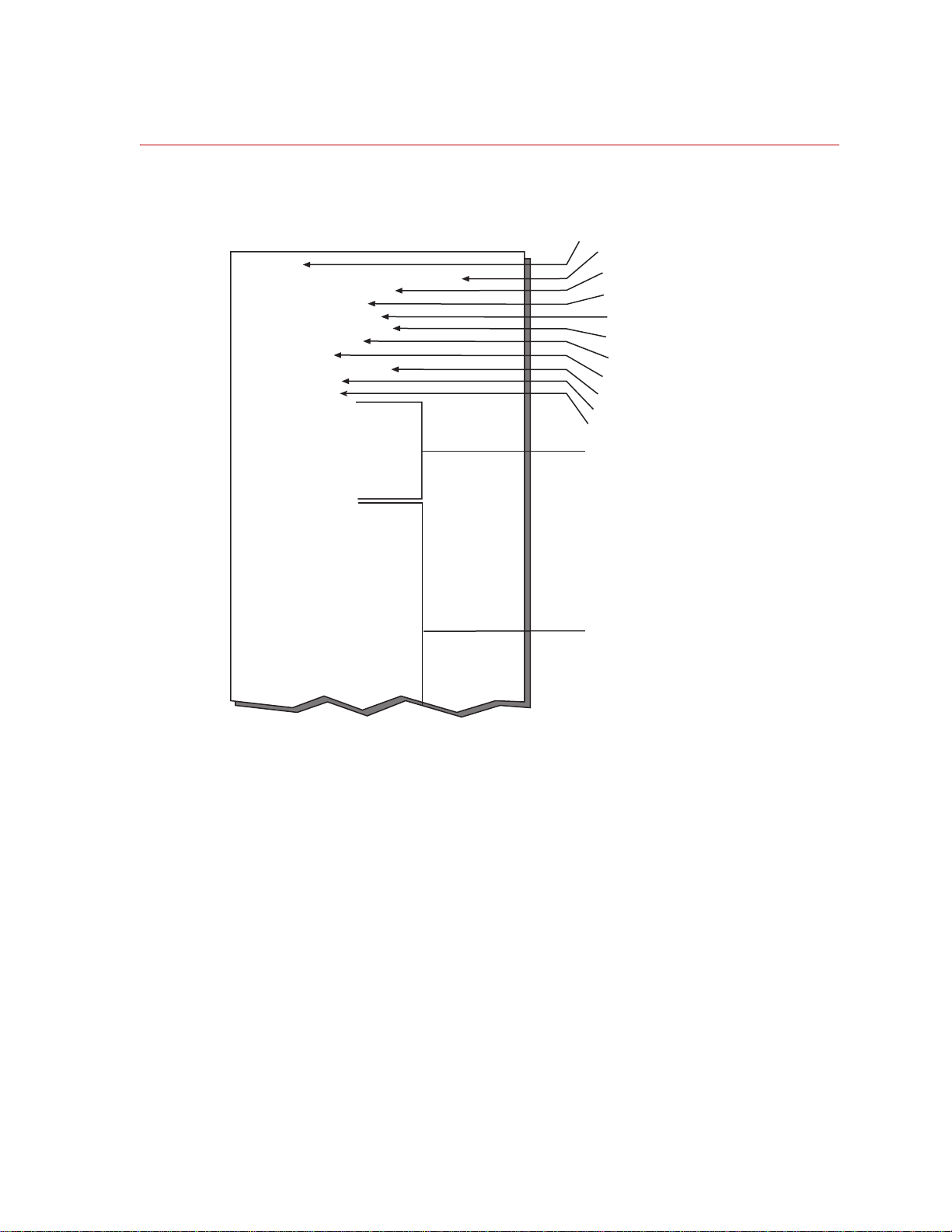
Calibration File Elements
[SWIFT]
Name=zero 3 after new tire
SerialNum=1234567
Normalization=0
InputSwitches=255
OutputPolarities=40
ZeroAlgorithm=4
AngleMode=0
AngleOffset=82.0898
AngleFixed=0
EncoderSize=0
ZFX1=0.103786
ZFX2=-0.023199
ZFY1=-0.094017
ZFY2=-0.184371
ZFY3=-0.225885
ZFY4=-0.269841
ZFZ1=-0.101343
ZFZ2=-0.045177
KFX1=0.196337
KFX2=0.195604
KFY1=0.169231
KFY2=0.166789
KFY3=0.167277
KFY4=0.16801
KFZ1=0.195849
KFZ2=0.196581
KMX=3.7558
KMYX=2.39805
KMYZ=2.5641
KMZ=3.75824
KFXFY=0.000611
KFXFZ=-0.00315
KFXMX=0.008864
KFXMY=-0.005348
SWIFT file identifier
Description of the file
Serial number of the
T
ransducer Interface (TI)
Internal calibration for the TI
Polarity of the six outputs
(default = 40)
Zero Algorithm
Angle Mode
Angle Offset
Fixed Angle
Bridge Zeroes
Do Not Modify
Calibration Gains
Do Not Modify
Setting for all input switches
(default = 255, all closed)
S20-33
Encoder Size
The following figure shows some elements of the calibration file:
Select a Zero Method
SWIFT 20 Sensors Setting up the Low-Profile Transducer Interface
Typical Calibration File
61
Page 62

Select a Zero Method
Items you may edit • OutputPolarities–defines the polarities of the six outputs. Change these
only if your application requires different polarities from those on the
transducer label.
• ZeroAlgorithm–selects a zero algorithm for the application.
• AngleMode–selects the mode used for determining the encoder sine and
cosine.
• AngleFixed–used for non-spinning applications.
• AngleOffset–used for spinning applications. Normally you do not need to
change this value.
• EncoderSize–defines the size of the encoder. The value will typically be 1
for the spinning slip ring.
• Zero Algorithms
The following table lists the different values available and the angle zero
and bridge zero functions that they perform:
Zero Algorithm Values Defined (p art 1 of 2)
Zero Algorithm When to Use Bridge Zero Angle Zero
0
Use this algorithm
for non-spinning
(road simulator)
applications.
When you press the Bridge
Zero button, the TI measures
the static transducer bridge
offsets. It sets up zero DACs
The Angle Zero button is nonfunctional.
to provide 0.0 V raw bridge
(AngleMode=1)
output.
The Bridge Zero LED will
light for 3–4 seconds, and will
go off when the zero process
is complete.
1
This is the
algorithm for
spinning (test
track) applications.
When you press the Bridge
Zero button, the TI will
collect one revolution of raw
bridge data, average the data,
and remove the DC offset by
You will need to
mechanically level
setting the zero DACs to the
average value.
the SWIFT sensor.
The Bridge Zero LED will
The transducer is
unloaded during
the zero process.
(AngleMode=0)
light continuously until the
wheel is turned for one
revolution (index-to-index).
After one revolution of data is
collect, it will flash (at
approximately 4 Hz) for 30
seconds while the bridge zero
values are computed.
When you press the Angle Zero
button, the TI will read the current
angle and use the value to set the
angle sum to 0.0 degrees.
The Angle Zero LED will light for a
few seconds while the TI sets the
angle offset value.
If you do not press the Angle Zero
button, the value for AngleOffset
will not be updated in the calibration
file.
The wheel must be rotated past the
encoder index pulse at least once
after power up so that the electronics
can determine the absolute angular
position.
2
Reserved for future
use.
Setting up the Low-Profile Transducer Interface
62
N/A N/A
SWIFT 20 Sensors
Page 63

Zero Algorithm Values Defined (p art 2 of 2)
Zero Algorithm When to Use Bridge Zero Angle Zero
Select a Zero Method
3
Use this algorithm
if you do not need
to mechanically
Both the Angle Zero and Bridge Zero buttons are functional. This
algorithm will perform both angle zero and bridge zero processes
when either of these buttons is pressed.
level the SWIFT
sensor
The transducer is
unloaded during
the zero process.
(AngleMode=0)
In the Bridge Zero process,
the TI will average the data
and remove the DC offset by
setting the zero DACs to the
average value.
In the Angle Zero process, the TI
will collect one revolution of raw
bridge data, perform a peak/valley
analysis via sine curve fit for X1, X2,
Z1, Z2, and determine the angle that
will result in positive Z facing
upward.
This process assumes that the wheel
is hanging, so that the peak vehicle Z
axis is read 180° out of phase
(transducer peaks are the weight of
the wheel, in a downward direction).
The angle determined is then shifted
by 180°.
4
This is the
recommended
Both the Angle Zero and Bridge Zero buttons are functional. This
algorithm will perform both angle zero and bridge zero processes.
algorithm for
spinning
applications.
You will need to
mechanically level
the SWIFT sensor
The Bridge Zero button is pressed when the Z beam is facing up.
The Angle Zero button is pressed after the sensor is rotated 90° in
either the plus or minus direction.
Using the data collected from these two positions, all bridge zeros and
angle zeros are computed.
The transducer is
unloaded during
the zero process.
(AngleMode=0)
SWIFT 20 Sensors Setting up the Low-Profile Transducer Interface
63
Page 64

Upload the Calibration File
Upload the Calibration File
A unique calibration file was loaded into the TI RAM by MTS before the
transducer and transducer interface were shipped. Use the program TIXFER to
retrieve the calibration file. TIXFER is a simple DOS-based program that will
prompt you for information.
1. Connect a communication cable from the laptop computer or PC to the TI.
2. Insert the SWIFT Transducer Interface Utilities diskette into the lapto p
computer or PC.
3. Go to a DOS shell and run the program TIXFER.
When you type in the command to run the program, you must specify the
communications port for data transfer. For example, enter TIXFER 1 to
specify COM1.
4. Enter 1 at the prompt to upload the calibration file. (See the illustration
below.)
5. Enter the address for the TI box at the prompt.
The address for the TI is determined by the setting of the address selector
switch on the front panel. If you are using more than one transducer, each TI
will have a different address.
6. Enter a file name.
The file name must use the DOS naming convention (xxxxxxxx.xxx).
7. Enter a description of the file.
You may enter the serial number of the transducer or descriptive words to
help you identify the correct calibration file.
Setting up the Low-Profile Transducer Interface
64
SWIFT 20 Sensors
Page 65

Upload the Calibration File
8. TIXFER will prompt you when the file has uploaded.
tixfer 1.7 beta ((10/25/04)
0...exit
1...Upload/Save a chassis
2...Restore/Download a chassis
Enter choice? 1
Enter TI box address? 1
Enter output specifications filename?
demo.cal
Enter description? demo upload
Allocating box...
Initializing box...
Uploading box...
Saving settings...
completed upload.
SWIFT 20 Sensors Setting up the Low-Profile Transducer Interface
65
Page 66
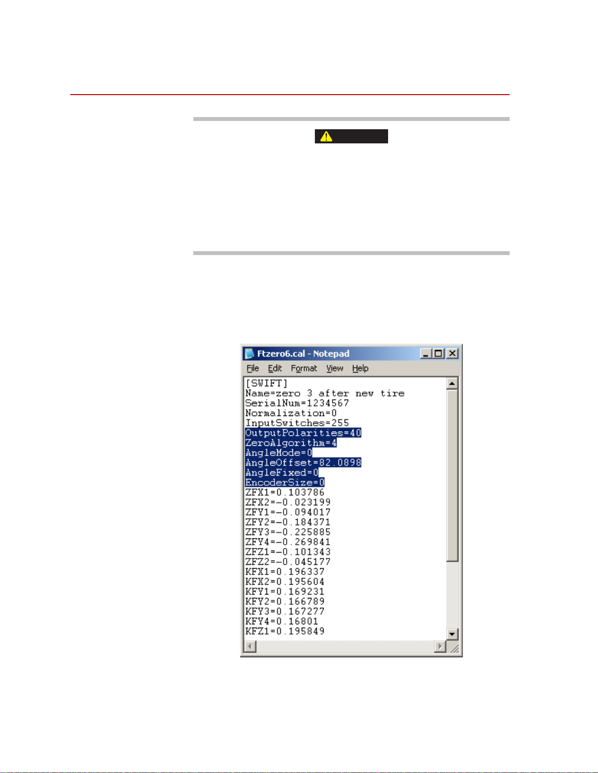
Edit the Calibration File
CAUTION
Edit the Calibration File
Do not change any other items in the calibration file.
The calibration file contains offset values for all of the bridge outputs.
Changing any of the items other th an those listed in the following procedure
will cause your calibration file to be incorrect.
Take care not to change any values except those listed in the following procedure.
If your calibration file is incorrectly changed, reload the original file from the
diskette provided by MTS.
What you need to
know
Before you make the changes to the Calibration file you will need to know how
your system is set up (a spinning or non-spinning configuration) and how you
want you data from each sensor formatted (the Output Polarities)
1. Open the calibration file using a text editor.
Setting up the Low-Profile Transducer Interface
66
SWIFT 20 Sensors
Page 67

Edit the Calibration File
2. If necessary, edit the value for OutputPolarities.
This value sets the polarity states of all six outputs (Mz, My, Mx, Fz, Fy, and
Fx) using the following binary scheme (the default configuration is
represented):
Mz My Mx Fz Fy Fx
5
4
Bit
2
2
3
2
22212
Bit Value 32 16 8 4 2 1
0
Example 1 0 1 0 0 0
= 4010 (default)
For example, if you want to invert Fx and Fy, and Mx and My, (making their
polarities opposite those shown on the labeling) you would make the
following changes:
Mz My Mx Fz Fy Fx
5
Bit
4
2
2
2322212
Bit Value 32 16 8 4 2 1
101000= 40
110011
* See the examples in the next table.
0
(old value)
10
= 5110 (new value)
*
SWIFT 20 Sensors Setting up the Low-Profile Transducer Interface
67
Page 68

Edit the Calibration File
S20-34
Front
Fz
UpFyOut
Fx
Aft
Fz
Up
Fx
Fore
Fy
Out
S20-35
Front
Fy
In
Fz
Up
Fx
Aft
Fy
In
Fx
Fore
Fz
Up
S20-41
Front
Fx
Aft
Fy
In
Fz
Up
Fx
Aft
Fy
Out
Fz
Up
Output Polarity Value
Example Output Polarities
Description
Direction of Positive
output from load on tire
when mounted on left
hand side of the vehicle
Direction of Positive
output from load on tire
when mounted on right
hand side of the vehicle
OutputPolarities = 40 Standard Setting from
MTS. Matches the axis
orientation on the front
cover of the SWIFT.
OutputPolarities = 51 Common setting to
alter the axis for-aft and
in-out lateral axis
OutputPolarities (left side) = 51
OutputPolarities (right side) = 40
Common setting for
vehicle coordinate
matching between the
two sides of the
vehicle.
+Fx = fore
+Fy = out from car, left
+Fz = up
+Mx, +My+, +Mz =
Right-hand rule about
Force axis
+Fx = aft
+Fy= into car, right
+Fz = up
+Mx, +My, +Mz =
Right-hand rule about
Force axis
+Fx = aft
+Fy= into car, right
+Fz = up
+Mx, +My, +Mz =
Right-hand rule about
Force axis
+Fx = aft
+Fy = out from car, right
+Fz = up
+Mx, +My, +Mz = Right-
hand rule about Force
axis
+Fx = fore
+Fy = into car, left
+Fz = up
+Mx, +My, +Mz = Right-
hand rule about Force
axis
+Fx = aft
+Fy = out from car, right
+Fz = up
+Mx, +My, +Mz = Right-
hand rule about Force
axis
3. Perform this step for spinning application. For non-spinning applications,
skip to Step 4.
A. Edit the value for ZeroAlgorithm.
The zero algorithm value that you specify will affect the operation of
the Angle Zero and Bridge Zero switches.
Set ZeroAlgorithm=1, 3 or 4
1
B. Edit the value for AngleMode.
Set the AngleMode=0
In this mode, the encoder pulses are summed in with the offset and the
resulting value addresses the sine and cosine RAM, which perform the
rotational transformation of the output signals.
1. See the Zero Algorithms discussion on page 62 to help determine which
algorithm to use.
68
Setting up the Low-Profile Transducer Interface
SWIFT 20 Sensors
Page 69

Edit the Calibration File
C. The AngleOffset value is used when you are operating in encoder
mode (spinning applications). This value is summed with the encoder
output count, and used to address the sine and cosine RAM when the
angle mode is set to 0 (encoder). Negative angles are converted to their
positive equivalent so that the readback value range is 0–360°.
The AngleOffset value is calculated by the TI during the zero process.
At the end of the process it is written to the calibration file.
There is no need to change this calculated value.
D. Edit the value for EncoderSize depending on the SWIFT Sensor being
used. For most applications this is EncoderSize=1 (sensor with slip
ring option)
4. Perform this step for non-spinning applications. For spinning applications,
skip to Step 5.
A. Edit the value for ZeroAlgorithm.
The zero algorithm value that you specify will affect the operation of
the Angle Zero and Bridge Zero switches.
Set ZeroAlgorithm=0
B. Edit the value for AngleMode.
Set the AngleMode=1
In this mode, the sine and cosine RAM address is fixed. The encoder is
not used, nor is the encoder offset.
C. Edit the value for AngleFixed.
The AngleFixed value is used for non-spinning applications. This
value addresses the sine and cosine RAM when the angle mode is set to
1 (fixed). Negative angles are converted to their positive equivalent so
that the readback value range is 0–360°.
You may set the fixed angle value when you are operating in fixed
angle mode (non-spinning applications) only if the transducer is rotated
from its correct Fz–Fx orientation on the road simulator. For
installations where the Fz-Fx orientation on the SWIFT cover(s) is
aligned with gravity. The correct setting is:
AngleFixed=0
If the SWIFT is installed at an angle to the desired Fz–Fx output axis,
set the AngleFixed value equal to the installed angle offset in degrees,
with clockwise rotation positive.
For example:AngleFixed = 45.
5. Save the changes and exit the editor.
SWIFT 20 Sensors Setting up the Low-Profile Transducer Interface
69
Page 70

Download the Calibration File
Download the Calibration File
Use the program TIXFER to download the modified calibration file to the TI.
1. Insert the diskette into the laptop computer or PC.
2. Go to a DOS shell and run the program TIXFER.
When you type in the command to run the program, you must specify the
communications port for data transfer. For example, enter TIXFER 1 to
specify COM1.
3. Enter 2 at the prompt to download the calibration file.
4. Enter the address for the TI box at the prompt.
The address for the TI is determined by the setting of the address selector
switch on the front panel. If you are using more than one transducer, each TI
will have a different address.
5. Enter the name of the file you wish to download.
The file must be in the same directory as the TIXFER program. The file
name must use the DOS naming convention (xxxxxxxx.xxx), which
means that you must type the full name and the extension.
6. TIXFER will prompt you when the file has successfully downloaded.
Setting up the Low-Profile Transducer Interface
70
SWIFT 20 Sensors
Page 71

7. Enter 0 at the prompt to exit the program.
tixfer 1.7 beta ((10/25/04)
0...exit
1...Upload/Save a chassis
2...Restore/Download a chassis
Enter choice? 2
Enter TI box address? 1
Enter input specifications filename?
demo.cal
Allocating box...
Initializing box...
Restoring settings...
Downloading box...
Completed download.
tixfer 1.7 beta ((10/25/04)
Download the Calibration File
0...exit
1...Upload/Save a chassis
2...Restore/Download a chassis
Enter choice? 0
Program completed
SWIFT 20 Sensors Setting up the Low-Profile Transducer Interface
71
Page 72

Download the Calibration File
Setting up the Low-Profile Transducer Interface
72
SWIFT 20 Sensors
Page 73

Installing the Transducer
Important This section includes information related to the Low-Profile
Transducer Interface (TI). Fo r SWIFT transducers designed to
operate with the newer Mini TI, there is a separate manual that
documents the transducer installation with the Mini TI (MTS part
number 100214316).
The SWIFT sensor can be installed on a vehicle at the test track or on an MTS
Series 329 Road Simulator in the test laboratory.
Contents Test Track Vehicle for Slip Ring Sensor 74
Attaching SWIFT Components to the Wheel Assembly 77
Attaching SWIFT and Wheel Assembly to the Vehicle 80
Installing the Low-Profile Transducer Interface Electronics 82
Setting up the SWIFT Sensor for Data Collection 85
Verifying the Quality of the Zero Procedure 95
Collecting Data 98
Road Simulator 100
Attaching SWIFT Components to the Fixturing 102
Zeroing the Low-Profile Transducer Interface 105
Communication Configurations 106
Cable Configurations 108
Transducers Designed to Operate with a Low-Profile TI but Using a Mini TI
For SWIFT transducers designed to operate with a Low-Profile but are using the
Mini TI, an adapter cable is needed; MTS part number 100224052. The
transducer and shunt cables are connected to one end of the adapter cable and the
other end is connected to J3 of the Mini TI.
SWIFT 20 Sensors Installing the Transducer
73
Page 74

Test Track Vehicle for Slip Ring Sensor
Test Track Vehicle for Slip Ring Sensor
Equipment required This procedure requires one person. To install the SWIFT 20A or SWIFT 20T
slip ring sensor, you will need the following equipment:
• Hub adapter (see next figure)
• Modified rim (see next figure)
• Anti-rotate assembly (including customer-supplied mounting arm)
• Small set of hex-head wrenches (both English and metric)
• Tube bender for the anti-rotate bar
• Tube cutter
• Metric socket head drive set (up to 14 mm) with extension
• 5/16-18 UNC tap
• Molykote g-n paste (MTS part number 011-010-207)
• Bolts
For SWIFT 20A Transducer
40 size M8 X 1.25 mm
8 size M5 X 0.8 mm
lug nuts
For SWIFT 20T Transducer
32 size M10 X 1.5 mm
12 size M8 X 1.25 mm
8 size M5 X 0.8 mm
Lug nuts
• Torque wrenches, capable of the following ranges:
14–28 N•m (10–20 lbf•ft);
28–54 N•m (20–40 lbf•ft),
81–136 N•m (60-100 lbf•ft);
7 N•m (60 lbf •in)
Installing the Transducer
74
• Cables (transducer and BNC, plus customer-supplied from transducer
interface to data recorder). If the SWIFT is designed to operate with the
Low-Profile TI and you have a Mini TI, you will need an adapter cable,
MTS part number 100224052.
• Tie wraps
• Data recorder
SWIFT 20 Sensors
Page 75

Test Track Vehicle for Slip Ring Sensor
S20-57
Modified Rim
Hub Adapter
Transducer
Slip Ring
Bracket
Slip Ring
Encoder
CAUTION
CAUTION
• 12 V power supply (for example, a car battery)
Slip Ring Installation Components (Test Track)
Importance of bolts Bolts provide exceptional clamp force at the transducer to rim/spindle interface.
• Bolts on the inner hub secure the hub adapter to the SWIFT sensor.
• Bolts on the outer ring secure the SWIFT sensor to the wheel rim (or road
simulator spindle adapter).
Note Make sure all bolts are in place and fully torqued during all tests.
Correct use of bolts reduces the safety hazard and ensures optimal
transducer performance.
Before you begin Observe the following safety conditions while you are attaching the SWIFT
sensor and components to the vehicle.
Do not pressure-wash the transducer or clean it with solvents that would
degrade its silastic seal.
Pressure-washing the transducer or cleaning it with certain solvents can
damage it or degrade its silastic seal.
Avoid pressure-washing the transducer. Use only solvents that will not degrade
the silastic seal.
Do not use high-pressure-air to clean debris from around the transducer
connectors.
High-pressure-air can damage the silastic seals.
Use a fine wire brush and low air-pressure [0.07 MPa (10 psi)] to clean debris
from around the transducer connectors.
SWIFT 20 Sensors Installing the Transducer
75
Page 76

Test Track Vehicle for Slip Ring Sensor
CAUTION
CAUTION
CAUTION
CAUTION
Do not lay the wheel flat while the transducer is attached to it.
When the wheel is laid flat with the transducer facing down the weight of the
wheel can damage the connectors.
Always hold the wheel upright when the transducer is attached to it. If needed,
have another person hold the tire upright while you tighten the bolts, or place the
wheel on a thin layer of foam to protect the connectors.
Do not under-torque the lug nuts.
Lug nuts that are not properly tightened can become loose during testing.
Loss of a wheel can cause damage to the test vehicle and transducer and
result in injury to personnel.
Always tighten the lug nuts to the torque rating recommended for the vehicle/
wheel.
Do not drop the slip ring bracket (spider).
Dropping the slip ring bracket can damage the slip ring or a connector.
Always use care when you handle the slip ring bracket.
Do not allow the mounting arm or anti-rotate arm to bump against any
portion of the wheel or wheel well.
The anti-rotate device should not bump against the wheel well or other
vehicle parts at any time. Any jarring of the anti-rotate arm will damage the
slip ring and/or the encoder.
Position the mounting arm and anti-rotate assembly so that full suspension travel
will not cause interference with the wheel well or any other part of the vehicle.
Installing the Transducer
76
SWIFT 20 Sensors
Page 77

Test Track Vehicle for Slip Ring Sensor
Attaching SWIFT Components to the Wheel Assembly
SWIFT 20 Fasteners
SWIFT 20A SWIFT 20T
M8 X 1.25 mm M10 X 1.5 mm
M5 X 0.8 mm M8 X 1.25 mm
M5 X 0.8 mm
MTS modified M12 X 1.5 mm
or 1/2–20UNF inch lug nuts
* For threaded spindle applications, customer supplied M12 or 1/2 in
fasteners of appropriate length and thread pitch are required.
MTS modified M12 X 1.5 mm
*
or 1/2–20UNF inch lug nuts
Procedure 1. Remove the current wheel from the test vehicle.
2. Clean all surfaces of the vehicle tire(s) and the modified rim(s). It is critical
that all surfaces be free of stones, burrs, and grease. Use a mild detergent
such as dish soap.
Important It is imperative that the mounting surfaces of the transducer be
protected from getting scratched. Any wheel components and work
surfaces that might come in contact with the transducer must be
clean, smooth, and free of debris
Mount the tire(s) on the modified rim(s).
3. Wipe the unpainted mating surfaces of the modified rim and the transducer
with a clean dry cloth.
4. Attach the transducer to the modified wheel rim. Hand tighten the bolts.
If environmental conditions warrant, coat each fastener with Birchwood
Casey Sheath RB1 rust preventative (or equivalent).
*
Lubricate the threads and under the heads of all fasteners, using Molykote
g-n paste.
SWIFT 20 Sensors Installing the Transducer
77
Page 78

Test Track Vehicle for Slip Ring Sensor
SWIFT 20T
Viewed from Pilot Side
Rim Pilot
Tabs (8)
SWIFT 20A
Viewed from Pilot Side
Rim Pilot
Tabs (8)
S20-16
1
2
3
4
5
6
7
8
9
16
19
10
1418
15
12
13
17
20
11
1
235
6
7
8
9
16
19
10
14
18
15
12
13
17
20
11
21
24
23
22
4
Inner Bolt Pattern
All bolts are M8
Outer Bolt Pattern
All bolts are M8
Inner Bolt Pattern
Bolts 14 are M8.
Bolts 520 are M10
Outer Bolt Pattern
Bolts 18 are M8.
Bolts 924 are M10
1
2
3
4
5
6
7
8
9
16
19
10
14
18
15
12
13
17
20
11
1
2
3
5
6
7
8
16
19
10
14
18
15
12
13
17
20
11
4
9
5. Attach the hub adapter to the transducer. Hand tighten the bolts
If environmental conditions warrant, coat each fastener with Birchwood
Casey Sheath RB1 rust preventative (or equivalent).
Lubricate the threads and under the heads of all fasteners, using Molykote
g-n paste.
A clearance of approximately 0.05 mm (0.002 in) is required between the
transducer and the hub adapter. You should not have to wedge the wheel into
the rim or the hub adapter into the SWIFT sensor.
78
Installing the Transducer
Bolt Torque Sequence
SWIFT 20 Sensors
Page 79

Test Track Vehicle for Slip Ring Sensor
6. Tighten the mounting bolts.
A. Following the sequence shown in the previous figure for the transducer
being installed, torque the inner hub bolts in two increments, as shown
in the following table.
Important For the SWIFT 20T, the M8 bolts in the inner bolt pattern (bolts 1–4
in the previous figure) must be torqued, as described, before
torquing the M10 bolts (bolts 5–20 in the previous figure).
Note To minimize negative clamping effects, you must torque the bolts in the
sequence shown.
Torque Increment SWIFT 20A SWIFT 20T
Bolt Size M8 M8 M10
1st Increment 14 N•m (10 lbf•ft) 14 N•m (10 lbf•ft) 27 N•m (20 lbf•ft)
Final Torque 27 N•m (20 lbf•ft) 27 N•m (20 lbf•ft) 54 N•m (40 lbf•ft)
B. Following the sequence shown in the previous figure for the transducer
being installed, torque the outer hub bolts in two increments as shown
in the previous table.
Important For the SWIFT 20T, the M8 bolts in the outer bolt pattern (bolts 1–8
in the previous figure) must be torqued, as described, before
torquing the M10 bolts (bolts 9–24 in the previous figure).
Note To minimize negative clamping effects, you must torque the bolts in the
sequence shown.
SWIFT 20 Sensors Installing the Transducer
79
Page 80

Test Track Vehicle for Slip Ring Sensor
Attaching SWIFT and Wheel Assembly to the Vehicle
1. Before installing the SWIFT and wheel assembly, attach the slip ring antirotate bracket to the vehicle.
Since the bracket is unique to each vehicle the slip ring anti-rotate bracket
must be provided by the customer. The following are guidelines for
manufacturing and locating the bracket. See the next figure.
• The bracket must be stiff, preferably steel or stiff aluminum tubing, so
as not to move or rotate when connected to an unsprung mass or
spindle which will allow the slip ring assembly to move with the tire as
the vehicle is moving or testing.
• The bracket must be positioned so as not to hit the fender at the
extreme end of the suspension travel.
• The bracket must maintain a minimum clearance from the tire so as not
to hit the tire when it is loaded and rotating.
2. Attach the wheel/transducer to the test vehicle.
Lubricate the lug bolt threads with Molykote g-n paste.
Tighten the lug nuts to the torque rating recommended for the wheel.
3. Attach the slip ring bracket (spider) and slip ring to the transducer.
A. The slip-ring bracket fits over the 10-pin connectors on the front of the
transducer at the locations labeled Board A and Board B. The slip-ring
bracket is similarly labeled to prevent connecting it the wrong way.
Note Use care when installing the slip-ring bracket. The 10-pin connectors are
keyed. The slip-ring bracket should be fitted on straight (without bending
or angling it) to make sure it engages both connectors simultaneously
and evenly.
B. Lubricate the threads and under the bolt heads of the eight M5 X 0.8
mm bolts with Molykote g-n paste. Insert them through the mounting
hole in the slip ring bracket and thread them into the transducer. T orque
them to 6.8 N•m (60 lbf•in).
C. Make sure that the covers on the shunt connectors are securely locked
in place. Each cover should be twisted until it snaps into the retaining
groove.
4. Attach the anti-rotate assembly to the anti-rotate bracket (installed earlier)
and the slip ring. If this is the first time the anti-rotate assembly is used on
this vehicle or if the mounting location has changed, perform Steps A and B,
otherwise proceed to Step C. (Refer to the next figure for guidelines.)
Installing the Transducer
80
A. Weld the steel tube sleeve to the customer-supplied customer supplied
anti-rotate bracket.
B. Bend the aluminum tube to fit over the wheel.
SWIFT 20 Sensors
Page 81

Test Track Vehicle for Slip Ring Sensor
Slip Ring
Assembly
or
Dependent on
Slip Ring/Encoder
Geometry
Slip Ring
Assembly
Suspension/
Unsprung Mass
Minimum Clearance
Typically approximately
6 mm (0.25 in) depending
on tire uniformity. Tire
must not hit bracket when
loaded or rotating.
Anti-Rotate Bracket
must be Stiff (preferably steel
or stiff aluminum tubing), so as
not to move or rotate when
connected to unsprung mass
or spindle, which will allow the
slip ring assembly to move with
the tire as the vehicle is
moving or testing.
Center line
of Wheel
Anti-Rotate
Assembly
6-32 X 1/4 in long
Socket Head
Cap Screw
Transducer
5/16-18 UNC
Low-head Socket Screw
19 mm (0.75 in) long
Steel
Sleeve
Modified Delrin Ball
15.875 mm (0.625 in)
diameter
Vehicle
Fender
Bracket must not hit
fender at extreme end
of suspension travel
Weld steel sleeve to
anti-rotate bracket
when assembly is
mounted on vehicle
S20-18
Anti-Rotate
Assembly
M4 X 0.7 mm
X10 mm long
or 8-32 X 3/8 in long
Socket Head
Cap Screw (qty 2)
Transducer
Output Cable
C. Measure, making bends as necessary, and cut the aluminum tube to
size.
MTS provides an extra long tube with a hinge welded at one end. After
fitting the tube to your test vehicle, cut off the excess length.
D. Tap the end of the aluminum tube 5/16-18 UNC X 1.00 inch deep.
E. Insert the low-head cap screw through the delrin ball.
F. Insert the aluminum tube into the steel sleeve.
G. Tighten the screws that attach the hinge joint to the slip ring assembly.
5. Attach the transducer output cable to the slip ring encoder connector and the
Slip Ring D-connector on the rear of the TI.
6. Secure the cable along its length so that ot will not become damaged during
data collection. (For example, tape it to the external mirror.)
Be sure to leave enough slack in the cable to allow for the full range of
wheel travel (jounce and steer).
SWIFT 20 Sensors Installing the Transducer
81
Page 82

Test Track Vehicle for Slip Ring Sensor
Installing the Low-Profile Transducer Interface Electronics
Important This section includes information related to the Low-Profile
Transducer Interface (TI). Fo r SWIFT transducers designed to
operate with the newer Mini TI, there is a separate manual that
documents the Mini TI (MTS part number 100214316).
The Transducer Interface (TI) electronics should be securely fastened to the
vehicle in a protected location. The TI box is designed to withstand the
accelerations associated with the body of a vehicle during rugged durability and
typical data acquisition testing.
The TI box can be located anywhere in the vehicle that is convenient. However,
if the TI is able to bounce around during data collection, it can bump against
another piece of equipment, pushing in the Zero button. If the Zero button is
pushed, you will lose all of the data.
Considerations Suitable locations for the TI box include the vehicle trunk, flatbed, interior floor,
or rear seat. Consider the following guidelines when you fasten the TI box(es) to
the vehicle:
• Mount the TI box in a position on or in the vehicle that is protected from
impact and high acceleration events.
• Do not expose the TI box to rain, snow, or other wet conditions.
• Orient the TI box horizontally.
• Multiple TI boxes may be rigidly attached to each other using optional
mounting straps.
• Place a thin foam or rubber material between TI boxes and any hard
mounting surface.
• Use ratcheting straps to provide a tight connection that will not loosen or
untie during testing.
• Do not use rubber cords to secure the TI box because they may stretch and
lose retention in the cord due to inertial forces.
Procedure 1. Connect all data cables from the TI to the data recorder.
There is one cable per channel of data from the TI to the data recorder.
These correspond to the three forces, three moments, and angular position.
Note Make sure that there is no tension or strain in the cables or at the cable
and connector junction. There should be some slack in the cables to
ensure that they are not pulled during testing.
Installing the Transducer
82
2. Connect the TI and the data recorder to a 12 V DC power source (such as a
vehicle battery).
SWIFT 20 Sensors
Page 83

Test Track Vehicle for Slip Ring Sensor
Ground to
vehicle frame
12 Vdc
Transducer Interface
S50-025
Data Recorder
Ground to
vehicle frame
12 Vdc
Transducer Interface
Transducer Interface
Transducer Interface
Transducer Interface
S50-026
Data Recorder
Note Some data acquisition systems may introduce electrical noise spikes to
the battery and cabling. The TI electronics should always be used with
the cleanest power supply possible. To reduce the likelihood of noise
spikes from the data recorder, we suggest running the power cables in
parallel, as shown in the following diagrams. If this does not remove the
noise spikes, separate batteries may be required.
3. Ground the TI and data recorder to the vehicle frame. (See the following
figures.)
Suggested Grounding for a single TI Box
Suggested Grounding for a Multiple TI Boxes
4. Secure the TI box so that it will not move during data collection.
Note If the TI box is not properly secured, it can bump against another piece of
equipment or a hard surface, pushing in the Zero button. If the Zero
SWIFT 20 Sensors Installing the Transducer
button is pushed, you will lose all of the data.
83
Page 84

Test Track Vehicle for Slip Ring Sensor
5. Verify that the shunt contacts are covered.
Make sure that the plugs on the slip ring bracket (spider) cover are in place
so that no water will enter the contacts.
Make sure that the bayonette covers on the shunt connectors are securely
locked in place. Each cover should be twisted until it snaps into the retaining
groove.
6. Turn on the TI and let it warm up for 15-20 minutes before you zero the
strain gage bridges.
Installing the Transducer
84
SWIFT 20 Sensors
Page 85

Test Track Vehicle for Slip Ring Sensor
CAUTION
CAUTION
Setting up the SWIFT Sensor for Data Collection
Important This section includes information related to the Low-Profile
Transducer Interface (TI). Fo r SWIFT transducers designed to
operate with the newer Mini TI, there is a separate manual that
documents the Mini TI (MTS part number 100214316).
To ensure accurate data collection, complete this setup procedure daily before
you begin testing.
The accuracy of the data that you collect depends on the ability of the SWIFT
electronics to “zero out” the forces and angles present in an initial, unloaded
state. During the Zero process, the TI box reads the transducer bridge values and
compensates for any offsets so that the bridge output is 0 at 0.0 V. It also reads
the current angle and compensates for any offset from the Z axis facing up.
You can ensure the success of the Zero procedure by taking these simple
precautions:
Considerations for
rotating a tire
Do not introduce extraneous forces or excessive accelerations into the
wheel while rotating it during the Zero process.
Any forces applied to the wheel, tire, rim, spider, or outer portion of the
transducer will cause a Bridge Zero error.
Make sure to apply only a gentle force at a steady rate to the inner hub while
rotating it.
Do not touch or bump the wheel while the transducer is zeroing.
T ouching or bumping the wheel will add loads to the transducer, resulting in
an erroneous zero reading.
Avoid all contact with the wheel while the transducer is zeroing. If you suspect that
the zero process is incorrect, begin again
When using a zero method that collects zero data while the sensor is rotating (i.e.,
algorithm 1 or 3), you must be careful to minimize the forces that are induced in
the transducer’s bridges.
SWIFT 20 Sensors Installing the Transducer
85
Page 86

Test Track Vehicle for Slip Ring Sensor
When using one of these zero methods, never rotate the tire directly, or by
grabbing the outer diameter of the transducer. This will introduce forces into the
transducer bridges that will result in a bad zero process and unreliable data.
• Rotate the tire at an even rate to avoid accelerations on the transducer.
• For positive-lock differentials, turn the other tire on the axle to cause the
desired rotation in the transducer you are zeroing.
• If you must touch the transducer to rotate the tire, carefully rotate the tire by
touching only the inner diameter of the transducer.
Choosing a Zero
method
Preferred method—Zero Algorithm 4 is the pr eferred method for configuring
the calibration file for spinning applications:
ZeroAlgorithm=4
AngleMode=0
This zero method samples all eight input bridges at two positions. After the data
is taken, all eight input channels are analyzed for signal offsets, and bridge zeroes
and angle zeroes are set in the TI.
Alternate methods—Zero Algorithm 1 and 3 are alternate methods for
configuring the calibration file:
ZeroAlgorithm=1
AngleMode=0
Zero Algorithm 1 samples all eight input bridges on every encoder tick, for one
complete revolution. After the data is taken, all eight input channels are analyzed
for signal offsets, and bridge zeroes are set in the TI. The angle offset is then
recorded in a separate step.
ZeroAlgorithm=3
AngleMode=0
Installing the Transducer
86
Zero Algorithm 3 may be more convenient for some test setups. However, you
must take care when using it, because it is susceptible to two types of errors:
• Noise spikes from power. These can be minimized by following the
grounding suggestions illustrated earlier in this chapter.
• Extraneous loads. Be very careful to rotate the wheel only by touching the
inner hub of the transducer or by engaging the axle (for some vehicles, this
means putting the vehicle in Park) and rotating the opposite wheel.
Because the SWIFT sensor measures loads applied to the outer edge of the
transducer, you should never touch the outer edge while you are spinning
the wheel. The rotation speed should be smooth, in order to avoid applying
inertial braking moments to the transducer.
SWIFT 20 Sensors
Page 87

Test Track Vehicle for Slip Ring Sensor
[SWIFT]
Name=zero 3 after new tire
SerialNum=1234567
Normalization=0
InputSwitches=255
OutputPolarities=40
ZeroAlgorithm=4
AngleMode=0
AngleOffset=82.0898
AngleFixed=0
EncoderSize=1
ZFX1=0.103786
ZFX2=-0.023199
ZFY1=-0.094017
ZFY2=-0.184371
ZFY3=-0.225885
ZFY4=-0.269841
ZFZ1=-0.101343
ZFZ2=-0.045177
KFX1=0.196337
KFX2=0.195604
KFY1=0.169231
KFY2=0.166789
KFY3=0.167277
KFY4=0.16801
KFZ1=0.195849
KFZ2=0.196581
KMX=3.7558
KMYX=2.39805
KMYZ=2.5641
KMZ=3.75824
KFXFY=0.000611
KFXFZ=-0.00315
KFXMX=0.008864
KFXMY=-0.005348
S20-38
Zero Algorithm
0 Non-spinning mode
1 Spinning mode (uses a digital
inclinometer for angle zero and
spinning the tire for the bridge zero
process
2 Not used
3 Spinning mode (uses spinning the
tire for both angle and bridge
processes)
4 Spinning mode (use a digital
inclinometer to define two positions
90° apart for the bridge zero and
angle zero processes.
Angle Mode
0 Spinning mode (obtains angle from
the encoder)
1 Fixed angle mode (used for test rigs
in the lab)
This zero method samples all eight input bridges on every encoder tick, for one
complete revolution. After the data is taken, all eight input channels are analyzed
for signal offsets, and the X and Z input channels are analyzed to determine the
angular zero point.
SWIFT 20 Sensors Installing the Transducer
Example of a .cal file
If Zero Algorithm=4 When you zero the TI, you want the vehicle to be fairly level and the transducer
to be as close to plumb as practical.
1. Install the SWIFT sensor(s) and data collection equipment on the vehicle.
2. Connect all cables and turn on the power to the TI boxes.
3. Let the TI boxes and transducers warm up for 15-20 minutes.
4. Run the TISTATUS program to compare the supply voltages to the
5. Verify that the calibration file is set up correctly for your testing application.
reference voltages.
Type: TIstatus <port#> <box#>
If the supply voltages vary more than 0.5 V from the reference voltages,
there is a power supply problem that must be resolved before you can
continue.
87
Page 88

Test Track Vehicle for Slip Ring Sensor
Axes Icon
S20-22
A. Download the spinning calibration file (xxxxxs.cal) to the computer
B. If necessary, modify the zero algorithm and angle mode to fit the
C. The EncoderSize parameter should be omitted or set to EncoderSize=1
D. Download the calibration file to the TI box.
Note If it becomes necessary to change the zero algorithm or angle mode
6. Elevate the vehicle with a lift, raise each corner with a jack.
7. Perform the zero procedure on each corner of the vehicle.
Use a digital inclinometer to zero the angle and strain gage bridges on the
transducer.
from the MTS Disk that corresponds to the serial number of the
transducer that you are setting up.
application/use requirements as described in, “Edit the Calibration
File,” on page 66.
after downloading the file to the TI, you can do so by using the
TISETZERO utility, as described in, “TISETZERO – Low-Profile
Transducer Interface Set Zero Method,” on page 56
A. Rotate the tire one full revolution so that the encoder can find the zero
index mark.
Note The encoder has a red dot on the mounting flange connected to the slip-
ring bracket and a black dot on the slip-ring connector housing where it
interfaces with the mounting flange. These dots, when aligned next to
each other, indicate the index mark is under the encoder sensor.
B. Rotate the tire as necessary, until the Fz on the axes icon (see the next
figure) printed on the transducer label is pointing up
C. Attach the level bracket so that it sits on top of the transducer. Insert the
locking pin through the bracket and into the pin pilot hole on the
transducer (see the next figure).
Installing the Transducer
88
SWIFT 20 Sensors
Page 89

Test Track Vehicle for Slip Ring Sensor
Digital Inclinometer
in this position
should read 0°, ±0.1°
Insert Lock Pin
in Pilot Hole
Level Bracket
S20-20
0.00°
Axes Icon
Digital Inclinometer
(alternate location)
in this position
should read 90°, ±0.1°
S20-21
Angle Zero
Switch and Indicator
Bridge Zero
Switch and Indicator
Note If the anti-rotate assembly interferes with the mounting of the digital
inclinometer, use the alternate mounting location shown.
D. Place the digital inclinometer on the bracket and rotate the tire until the
inclinometer reads 0.0°, ±0.1° (or 90.0°, ±0.1° if the alternate position
is used).
E. Push the Bridge Zero button on the front of the TI box. The LED will
turn on for a few seconds, then start blinking rapidly. The Angle Zero
indicator will start blinking slowly.
F. Remove the digital inclinometer and level bracket.
G. Rotate the tire 90° in either direction.
H. Attach the level bracket so that it again sits on top of the transducer.
Insert the locking pin through the bracket and into the pin pilot hole on
the transducer.
SWIFT 20 Sensors Installing the Transducer
89
Page 90

Test Track Vehicle for Slip Ring Sensor
Digital Inclinometer
(alternate location)
in this position
should read 90°, ±0.1°
Digital Inclinometer
in this position
should read 0°, ±0.1°
Insert Lock Pin in
Pilot Hole
Level Bracket
S20-23
0.00°
Rotate
Transducer
+ or 90°
I. Place the digital inclinometer on the bracket and rotate the tire until the
inclinometer reads 0.0°, ±0.1° (or 90.0°, ±0.1° if the alternate position
is used).
If Zero Algorithm=1 When you zero the TI, you want the vehicle to be fairly level and the transducer
J. Push the Angle Zero button on the front of the TI box. The Angle Zero
indicator will light for a few seconds, then both the Bridge Zero and
Angle Zero indicators should turn off.
Note If the red Fail indicator lights momentarily and the Bridge Zero and
Angle Zero indicators end up blinking slowly, problems were detected
with the zero. Try repeating the procedure. Use TISTATUS for a more
detailed explanation of the problem. If you continue to have an error,
consult the chapter, “Troubleshooting,” on page 127.
K. Rotate the transducer slightly to update the rotational transformation.
At this point the TI should be reading absolute forces in the vehicle
coordinate system.
L. Perform, “Verifying the Quality of the Zero Procedure,” on page 95.
M. Look at your data acquisition system to verify that the SWIFT sensor is
gathering data.
to be as close to plumb as practical.
1. Install the SWIFT sensor(s) and data collection equipment on the vehicle.
2. Connect all cables and turn on the power to the TI boxes.
3. Let the TI boxes and transducers warm up for 15-20 minutes.
Installing the Transducer
90
SWIFT 20 Sensors
Page 91

Test Track Vehicle for Slip Ring Sensor
4. Run the TISTATUS program to compare the supply voltages to the
reference voltages.
Type: TIstatus <port#> <box#>
If the supply voltages vary more than 0.5 V from the reference voltages,
there is a power supply problem that must be resolved before you can
continue.
5. Verify that the calibration file is set up correctly for your testing application.
A. Download the spinning calibration file (xxxxxs.cal) to the computer
from the MTS Disk that corresponds to the serial number of the
transducer that you are setting up.
B. If necessary, modify the zero algorithm and angle mode to fit the
application/use requirements as described in, “Edit the Calibration
File,” on page 66.
C. The EncoderSi ze parameter shoul d be omitted or set to EncoderSize=1
D. Download the calibration file to the TI box.
Note If it becomes necessary to change the zero algorithm or angle mode
after downloading the file to the TI, you can do so by using the
TISETZERO utility, as described in, “TISETZERO – Low-Profile
Transducer Interface Set Zero Method,” on page 56
6. Put the vehicle on a lift or jack up the corner of the vehicle on which the
SWIFT sensor is mounted.
Important Place wheel chocks under the wheels on the ground or otherwise
restrain the vehicle to prevent it from moving.
7. Push the Bridge Zero button. Only the Bridge Zero indicator will light.
8. Gently spin by hand, the wheel on the opposite side of the vehicle for two
revolutions. Be careful not to allow the wheel to stop or reverse direction.
This will cause the wheel you are zeroing to spin without load.
Note For rear wheels or wheels where this cannot be done, carefully spin the
wheel to be zeroed by gently contacting only the hub adapter bolted to
the SWIFT sensor.
9. Stop spinning the wheel when the Bridge Zero indicator begins to blink at a
rate of 4 Hz and continues blinking for about one minute.
The Bridge Zero indicator will then turn off, indicating completion of the
Bridge Zero procedure.
10. Perform the Angle Zero procedure.
Use a digital inclinometer to zero the angle on the transducer, then rotate the
tire to zero the strain gage bridges.
A. Rotate the tire one full revolution so that the encoder will pass the zero
index mark at least once.
SWIFT 20 Sensors Installing the Transducer
91
Page 92
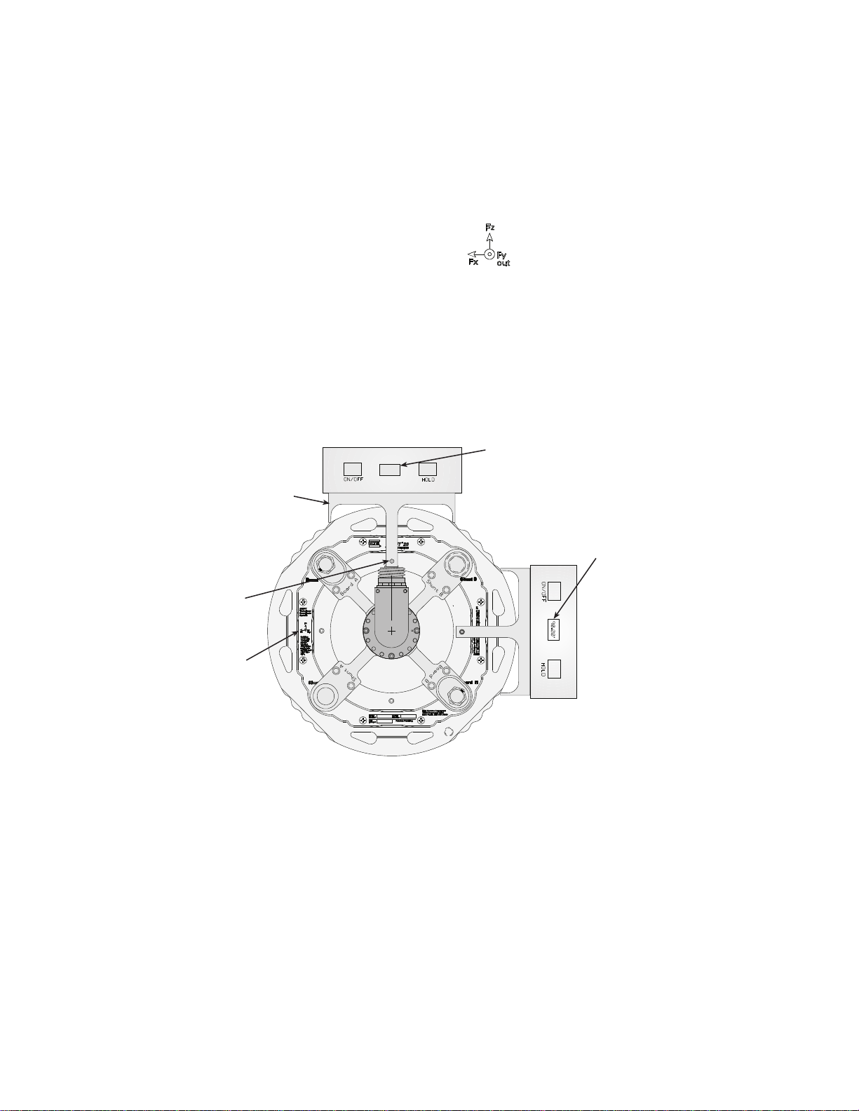
Test Track Vehicle for Slip Ring Sensor
Axes Icon
S20-22
Digital Inclinometer
in this position
should read 0°, ±0.1°
Insert Lock Pin
in Pilot Hole
Level Bracket
S20-20
0.00°
Axes Icon
Digital Inclinometer
(alternate location)
in this position
should read 90°, ±0.1°
Note The encoder has a red dot on the mounting flange connected to the slip-
B. Rotate the tire as necessary, until the Fz on the axes icon (see the next
C. Attach the level bracket so that it sits on top of the transducer. Insert the
Note If the anti-rotate assembly interferes with the mounting of the digital
ring bracket and a black dot on the slip-ring connector housing where it
interfaces with the mounting flange. These dots, when aligned next to
each other, indicate the index mark is under the encoder sensor.
figure) printed on the transducer label is pointing up
locking pin through the bracket and into the pin pilot hole on the
transducer (see the next figure).
inclinometer, use the alternate mounting location shown.
Installing the Transducer
92
D. Place the digital inclinometer on the bracket and rotate the tire until the
inclinometer reads 0.0°, ±0.1° (or 90.0°, ±0.1° if the alternate position
is used.
E. Push the Angle Zero button on the front of the TI box. The Angle Zero
indicator will turn on for a few seconds, then turn off indicating that the
Angle Zero procedure is complete.
11. After completing the Bridge and Angle Zero procedures, rotate the wheel
one full revolution clockwise.
This allows the electronics to locate the index pulse for the encoder.
Note The wheel must rotate one-half revolution in the same direction and then
pass over the encoder index point before data collection is started.
SWIFT 20 Sensors
Page 93

Test Track Vehicle for Slip Ring Sensor
S20-21
Angle Zero
Switch and Indicator
Bridge Zero
Switch and Indicator
12. Perform, “Verifying the Quality of the Zero Procedure,” on page 95.
13. Look at your data acquisition system to verify that the SWIFT sensor is
gathering data.
If Zero Algorithm=3 When you zero the TI, you want the vehicle to be fairly level and the transducer
to be as close to plumb as practical.
1. Install the SWIFT sensor(s) and data collection equipment on the vehicle.
2. Connect all cables and turn on the power to the TI boxes.
3. Let the TI boxes and transducers warm up for 15–20 minutes.
4. Run the TISTATUS program to compare the supply voltages to the
reference voltages.
Type: TIstatus <port#> <box#>
If the supply voltages vary more than 0.5 V from the reference voltages,
there is a power supply problem that must be resolved before you can
continue.
5. Verify that the calibration file is set up correctly.
A. Download the calibration file (xxxxx.cal) to the computer from the
MTS Disk that corresponds to the serial number of the transducer that
you are setting up.
B. If necessary, modify the zero algorithm and angle mode to fit the
application/use requirements as described in, “Edit the Calibration
File,” on page 66
C. For slip-ring transducers, the EncoderSize parameter should be omitted
or set to EncoderSize=1.
D. Download the calibration file to the TI box.
Note If it becomes necessary to change the zero algorithm or angle mode
after downloading the file to the TI, you can do so by using the
TISETZERO utility, as described in, “TISETZERO – Low-Profile
Transducer Interface Set Zero Method,” on page 56
6. Elevate the vehicle with a lift, or raise each corner with a jack.
7. Perform the zero procedure on each corner of the vehicle. Both the angle
and bridge zeros are computed by rotating the tire.
A. Push either the Angle Zero or Bridge Zero button on the front of the
TI box. Both indicators will light.
SWIFT 20 Sensors Installing the Transducer
93
Page 94

Test Track Vehicle for Slip Ring Sensor
B. Rota te the tire 1 1/4 to 2 revolutions, until the Bridge Zero indicator
C. If the Bridge Zero indicator continues to slowly flash after 2 minutes,
D. Perform, “Verifying the Quality of the Zero Procedure,” on page 95.
E. Look at your data acquisition system to verify that the SWIFT sensor is
starts flashing. Follow the guidelines in, “Considerations for rotating a
tire,” on page 85.
or if the red Fail indicator flashes, there is an error in the zero process.
Run TIST ATUS to find out more information. Repeat Steps A and B. If
you continue to have an error, consult the chapter, “Troubleshooting,”
on page 127
gathering data.
Installing the Transducer
94
SWIFT 20 Sensors
Page 95

Verifying the Quality of the Zero Procedure
Important This section includes information related to the Low-Profile
Transducer Interface (TI). Fo r SWIFT transducers designed to
operate with the newer Mini TI, there is a separate manual that
documents the Mini TI (MTS part number 100214316).
Perform the following consistency checks for each SWIFT sensor while the
vehicle (or corner) is elevated.
1. Does Fz measure the approximate weight of the tire/rim assembly?
2. Is Fx small (less than 0.1% of the rated load)?
3. What is the variance in Fz (modulation) when the tire is slowly rotated?
4. When the vehicle is on the ground, is the Fz reading approximately equal to
the corner weight of the vehicle? (See, “Effect of Zero Reference on SWIFT
Output,” on page 96.)
Acceptable Variations for Fx, Fz Readings
Transducer Model Max Rated Load
(Fx, Fz)
Fx Reading
with Vehicle Lifted
Test Track Vehicle for Slip Ring Sensor
Fz Modulation
with Vehicle Lifted
SWIFT 20 A (Aluminum)
SWIFT 20T (Titanium)
21 kN 0.1% (±15–20 N) 0.2% (20–40 N)
30 kN 0.1% (±25–30 N) 0.2% (40–60 N)
5. Perform a Shunt calibration on each transducer.
A. Elevate the vehicle on a lift, or jack up each corner.
B. Connect the shunt calibration cables from the Shunt A, Shunt B
connectors on the front of the transducer to the Shunt A, Shunt B
connectors on the back of the TI box (see the next figure).
C. Connect the signal cable from the slip ring to the Slip Ring connector
on the back of the TI box.
SWIFT 20 Sensors Installing the Transducer
95
Page 96

Test Track Vehicle for Slip Ring Sensor
Connect to
Data Acquisition
System
Shunt B
Shunt A
Board B
Board A
S20-24
D. Press the Shunt button on the front of the TI box, or use option 5 in the
Connect the shunt calibration cables
TISHUNT program.
The shunt indicator will light continuously for 30–45 seconds. If the
indicator continues to flash after shunt calibration is complete, the
shunt calibration has failed.
Effect of Zero
Reference on SWIFT
Output
6. Verify that the outputs from the TI box matches those on the calibration
report.
Use either the TISHUNT or TIXFER program to look at the shunt values of
the individual bridges.
The shunt calibration will fail if the measured shunt values are >2% of the
reference values that were set at the factory. Typically, the shunt values will
vary a maximum of 0.20-0.30 V from the reference values.
Refer to the chapter, “Troubleshooting,” on page 127, for more information
on dealing with shunt calibration failures.
When the SWIFT sensor is used in spinning applications, it is important that a
correct absolute zero of each strain gage bridge is used to ensure the proper
computation and transformation of the transducer outputs to a non-rotating
vehicle coordinate system. An error in the absolute zero of each bridge will
produce a one-time-per-revolution modulation error in the output signals. To
achieve absolute zero of each bridge, the zeroing process must account for the
tare weight acting on the transducer.
When the vehicle is lifted and the tire and wheel assembly are suspended, the
mass of the tire, rim, outer diameter fasteners, and outer ring of the transducer are
all reacted through the beams of the transducer. With gravity acting on this outer
tire/rim assembly, the SWIFT sensor measures a vertical force pulling down on
the transducer.
Installing the Transducer
96
The SWIFT output cannot be zero, because it is not possible to set the vehicle on
the ground precisely enough that the ground supports only the outer tire/rim
weight.
SWIFT 20 Sensors
Page 97

Test Track Vehicle for Slip Ring Sensor
As the vehicle is set completely on the ground, the output from the SWIFT sensor
will read the corner weight of the vehicle from the reference point of the
transducer. The output of the SWIFT sensor will be slightly less than the total
corner weight of the vehicle, because the SWIFT sensor is inboard of the outer
tire and rim assembly, and will therefore not measure the weight of the outer tire
and rim assembly.
SWIFT 20 Sensors Installing the Transducer
97
Page 98

Test Track Vehicle for Slip Ring Sensor
Collecting Data
Important This section includes information related to the Low-Profile
After you zero the TI, you are ready to collect data.
Note If you turn off power to the TI boxes, the zero values will remain valid, but
1. Spin the wheel twice to ensure that the encoder tick is correct.
Transducer Interface (TI). Fo r SWIFT transducers designed to
operate with the newer Mini TI, there is a separate manual that
documents the Mini TI (MTS part number 100214316).
the encoder will need to find the index pulse to properly convert the
rotating coordinates to stationary coordinates. The transducer outputs
will not be correct until this happens.
To reset the encoder, roll the vehicle either forward or backward so that
the tire completes at least one revolution. This can be accomplished
while driving to the test area, or if the vehicle is on a lift in the garage
area, rotate the tire according to the guidelines in, “Considerations for
rotating a tire,” on page 85.
Spinning the wheel after you have completed the zero process will ensure
that the encoder is correctly referenced to the index pulse. Otherwise, the
data collected during the first revolution will be flawed.
2. Remove the vehicle from the lift or jacks.
3. Secure the connector that attaches the signal cable to the top of the slip ring
with high quality duct or electrical tape.
This will prevent dust, dirt, and water from entering the connector and
causing wear on the pins and sockets.
4. Verify that the shunt contacts are covered.
Ensure that the plugs on the slip ring bracket (spider) cover are in place so
that no water will enter the contacts.
Ensure that the covers on the shunt connectors are securely locked in place.
Each cover should be twisted until it snaps into the retaining groove.
5. Perform a final inspection of the SWIFT sensor and the electronics to ensure
that everything is secure and the TI is on.
The zero data is saved at the end of each completed procedure. If the TI is
off, the zero data will not be lost. However, due to thermal conditions that
could affect your data, if the TI is powered off for an extended period of
time (such as over night), you must repeat the zero process.
Installing the Transducer
98
Note Rezeroing the transducer is good practice when thermal changes occur.
Rezeroing the transducer at conditions and temperatures closest to the
test conditions will provide a more accurate zero and reduce thermal
errors.
6. Turn on the data recorder.
7. Start data collection.
SWIFT 20 Sensors
Page 99

Test Track Vehicle for Slip Ring Sensor
CAUTION
CAUTION
WARNING
WARNING
Important Before beginning data collection, read the cautions on the next
page.
Do not allow the SWIFT assembly to bump into any hard surfaces while you
are driving the vehicle.
Bumping the SWIFT assembly into hard surfaces such as garage doors,
ramps and railings will damage the anti-rotate device, cable, slip ring, slip
ring bracket (spider), and transducer.
The SWIFT assembly will protrude approximately four inches (102 mm) from the
side of the vehicle. Remember to allow extra space on each side of the test
vehicle as you enter and exit areas with possible hazards.
Do not drive through tall grass and brush.
Driving through tall grass and brush can damage the cable and tear off the
slip ring.
Avoid areas of the test track with tall grass and brush.
Do not use the SWIFT sensor on public roads.
Public use or use on public roads could endanger the public.
Use the SWIFT sensor only on closed courses where the loads and load cycles
are recorded and managed within the prescribed limits. Only experienced test
vehicle drivers should operate a vehicle with the SWIFT sensor attached
Do not use the SWIFT sensor after excessive loading or load cycles.
The SWIFT sensor has a limited load life. Excessive loading or load cycles
could cause a fracture of the transducer, wheel rim, hub adapter, or
fasteners and can result in injury or death.
Always be aware of the maximum full scale loads appropriate for your transducer.
Upon approaching a prescribed limit, return the transducer with the recorded load
cycles to MTS for physical inspection and analysis of the load cycle history
SWIFT 20 Sensors Installing the Transducer
99
Page 100

Road Simulator
CAUTION
CAUTION
CAUTION
Road Simulator
Before you begin Angular correction is required on the test track only. If you are using the same
transducer(s) for non-spinning simulation testing you must load the correct
software into the TI.
The SWIFT sensor must be attached to the test fixture before the vehicle is
mounted.
Clean all surfaces. It is critical that all surfaces be free of stones, burrs, and
grease.
Do not pressure-wash the transducer or clean it with solvents that would
degrade its silastic seal.
Pressure-washing the transducer or cleaning it with certain solvents can
damage it or degrade its silastic seal.
Avoid pressure-washing the transducer. Use only solvents that will not degrade
the silastic seal.
Do not use high-pressure-air to clean debris from around the transducer
connectors.
High-pressure-air can damage the silastic seals.
Use a fine wire brush and low air-pressure [0.07 MPa (10 psi)] to clean debris
from around the transducer connectors.
Do not under-torque the lug nuts.
Lug nuts that are not properly tightened can become loose during testing.
Loss of a wheel can cause damage to the test vehicle and transducer and
result in injury to personnel.
Always tighten the lug nuts to the torque rating recommended for the vehicle/
wheel.
Installing the Transducer
100
SWIFT 20 Sensors
 Loading...