

Page 1

be certain.
m
SWIFT® 10 ATV Sensor
Product Information
Spinning Wheel Integrated Force Transducer
For Recreational and Small Vehicles
100-183-736 C
Page 2

Copyright information © 2008 MTS Systems Corporation. All rights reserved.
Trademark information MTS, SWIFT, TestStar, and TestWare are registered trademarks of MTS Systems
Corporation within the United States. These trademarks may be protected in
other countries.
Microsoft, Windows, Windows for Workgroups, Windows 95, and Windows NT
are registered trademarks of Microsoft Corporation. Apple and Macintosh are
registered trademarks of Apple Computer, Inc. UNIX is a registered trademark of
The Open Group. LabVIEW is a registered trademark of National Instruments
Corporation.
Publication information
MANUAL PART NUMBER PUBLICATION DATE
100-183-736 A February 2008
100-183-736 B April 2008
100-183-736 C November 2008
2
Page 3

Contents
Technical Support 7
How to Get Technical Support 7
Before You Contact MTS 7
If You Contact MTS by Phone 9
Problem Submittal Form in MTS Manuals 10
Preface 11
Before You Begin 11
Conventions 12
Documentation Conventions 12
Hardware Overview 15
Overview 16
Spinning Applications (Track or Road) 18
Non-spinning Applications (Laboratory) 19
Construction 20
Design Features 23
Coordinate System 24
Specifications 26
Calibration 30
Transducer Interface 32
TI Front Panel 35
TI Rear Panel 36
Interfacing with RPC 37
Software Utilities 39
Introduction 40
TI2STATUS - Transducer Interface Status 41
Description of TI2STATUS Indications 41
TI2XFER - Transducer Interface Transfer 43
TI2SHUNT - Transducer Interface Shunt 45
Setting Up Shunt Calibration Reference Values 48
Error Messages 49
SWIFT 10 ATV Sensors Contents
3
Page 4

Setting up the Transducer Interface 51
USB driver installation 52
Select a Zero Method 54
Calibration File Elements 55
Upload the Calibration File 56
Edit the Calibration File 57
Download the Calibration File 60
Installing the Transducer 61
Hazard Icon 62
Road and Track Vehicles 63
Attaching SWIFT Components to the Vehicle 67
Attaching Anti-rotate Assemblies 70
Installing the Transducer Interface Electronics 74
Setting up the SWIFT Sensor for Data Collection 77
Verifying the Quality of the Zero Procedure 80
Collecting Data 82
Road Simulator 85
Attaching SWIFT Components to the Fixturing 88
Zeroing the Transducer Interface 92
Analyzing SWIFT Data 97
The Data 98
Fx Data (Longitudinal Force) 99
Fz Data (Vertical Force) 101
Mx Data (Overturning Moment) 102
My Data (Brake Moment) 105
Acceleration and Braking Events Example 107
Slalom Curve Driving Example 109
Maintenance 111
Transducer 112
Transducer Interface 114
Cables 115
4
Contents
SWIFT 10 ATV Sensors
Page 5

Troubleshooting 117
Assembly Drawings 129
Cable Drawings 130
SWIFT 10 Mechanical Drawings 136
SWIFT 10 ATV Sensors Contents
5
Page 6

6
Contents
SWIFT 10 ATV Sensors
Page 7

Technical Support
How to Get Technical Support
Start with your
manuals
Technical support
methods
MTS web site
www.mts.com
E-mail techsupport@mts.com
Telephone MTS Call Center 800-328-2255
Fax 952-937-4515
Technical support
outside the U.S.
The manuals supplied by MTS provide most of the information you need to use
and maintain your equipment. If your equipment includes MTS software, look
for online help and README files that contain additional product information.
If you cannot find answers to your technical questions from these sources, you
can use the internet, e-mail, telephone, or fax to contact MTS for assistance.
MTS provides a full range of support services after your system is installed. If
you have any questions about a system or product, contact MTS in one of the
following ways.
The MTS web site gives you access to our technical support staff by means of a
Technical Support link:
www.mts.com > Contact MTS > Service & Technical Support
Weekdays 7:00 A.M. to 5:00 P.M., Central Time
Please include “Technical Support” in the subject line.
For technical support outside the United States, contact your local sales and
service office. For a list of worldwide sales and service locations and contact
information, use the Global MTS link at the MTS web site:
www.mts.com > Global MTS > (choose your region in the right-hand
column) > (choose the location closest to you)
Before You Contact MTS
MTS can help you more efficiently if you have the following information
available when you contact us for support.
Know your site
number and system
number
SWIFT 10 ATV Sensors Technical Support
The site number contains your company number and identifies your equipment
type (material testing, simulation, and so forth). The number is usually written on
a label on your MTS equipment before the system leaves MTS. If you do not
have or do not know your MTS site number, contact your MTS sales engineer.
Example site number: 571167
When you have more than one MTS system, the system job number identifies
which system you are calling about. You can find your job number in the papers
sent to you when you ordered your system.
Example system number: US1.42460
7
Page 8

Know information from
prior technical
If you have contacted MTS about this problem before, we can recall your file.
You will need to tell us the:
assistance
• MTS notification number
• Name of the person who helped you
Identify the problem Describe the problem you are experiencing and know the answers to the
following questions:
• How long and how often has the problem been occurring?
• Can you reproduce the problem?
• Were any hardware or software changes made to the system before the
problem started?
• What are the model numbers of the suspect equipment?
• What model controller are you using (if applicable)?
• What test configuration are you using?
Know relevant
computer information
Know relevant
software information
If you are experiencing a computer problem, have the following information
available:
• Manufacturer’s name and model number
• Operating software type and service patch information
• Amount of system memory
• Amount of free space on the hard drive in which the application resides
• Current status of hard-drive fragmentation
• Connection status to a corporate network
For software application problems, have the following information available:
• The software application’s name, version number, build number, and if
available, software patch number. This information is displayed briefly
when you launch the application, and can typically be found in the “About”
selection in the “Help” menu.
• It is also helpful if the names of other non-MTS applications that are
running on your computer, such as anti-virus software, screen savers,
keyboard enhancers, print spoolers, and so forth are known and available.
Technical Support
8
SWIFT 10 ATV Sensors
Page 9

If You Contact MTS by Phone
Your call will be registered by a Call Center agent if you are calling within the
United States or Canada. Before connecting you with a technical support
specialist, the agent will ask you for your site number, name, company, company
address, and the phone number where you can normally be reached.
If you are calling about an issue that has already been assigned a notification
number, please provide that number. You will be assigned a unique notification
number about any new issue.
Identify system type To assist the Call Center agent with connecting you to the most qualified
technical support specialist available, identify your system as one of the
following types:
• Electromechanical materials test system
• Hydromechanical materials test system
• Vehicle test system
• Vehicle component test system
• Aero test system
Be prepared to
troubleshoot
Write down relevant
information
After you call MTS logs and tracks all calls to ensure that you receive assistance and that action
Prepare yourself for troubleshooting while on the phone:
• Call from a telephone when you are close to the system so that you can try
implementing suggestions made over the phone.
• Have the original operating and application software media available.
• If you are not familiar with all aspects of the equipment operation, have an
experienced user nearby to assist you.
Prepare yourself in case we need to call you back:
• Remember to ask for the notification number.
• Record the name of the person who helped you.
• Write down any specific instructions to be followed, such as data recording
or performance monitoring.
is taken regarding your problem or request. If you have questions about the status
of your problem or have additional information to report, please contact MTS
again and provide your original notification number.
SWIFT 10 ATV Sensors Technical Support
9
Page 10

Problem Submittal Form in MTS Manuals
Use the Problem Submittal Form to communicate problems you are experiencing
with your MTS software, hardware, manuals, or service which have not been
resolved to your satisfaction through the technical support process. This form
includes check boxes that allow you to indicate the urgency of your problem and
your expectation of an acceptable response time. We guarantee a timely
response—your feedback is important to us.
The Problem Submittal Form can be accessed:
• In the back of many MTS manuals (postage paid form to be mailed to MTS)
• www.mts.com > Contact Us > Problem Submittal Form (electronic form to
be e-mailed to MTS)
Technical Support
10
SWIFT 10 ATV Sensors
Page 11

Preface
Before You Begin
Safety first! Before you attempt to use your MTS product or system, read and understand the
Safety manual and any other safety information provided with your system.
Improper installation, operation, or maintenance of MTS equipment in your test
facility can result in hazardous conditions that can cause severe personal injury or
death and damage to your equipment and specimen. Again, read and understand
the safety information provided with your system before you continue. It is very
important that you remain aware of hazards that apply to your system.
Other MTS manuals In addition to this manual, you may receive additional MTS manuals in paper or
electronic form.
If you have purchased a test system, it may include an MTS System
Documentation CD. This CD contains an electronic copy of the MTS manuals
that pertain to your test system, including hydraulic and mechanical component
manuals, assembly drawings and parts lists, and operation and preventive
maintenance manuals. Controller and application software manuals are typically
included on the software CD distribution disc(s).
SWIFT 10 ATV Sensors Preface
11
Page 12

Conventions
DANGER
WARNING
CAUTION
Conventions
Documentation Conventions
The following paragraphs describe some of the conventions that are used in your
MTS manuals.
Hazard conventions As necessary, hazard notices may be embedded in this manual. These notices
contain safety information that is specific to the task to be performed. Hazard
notices immediately precede the step or procedure that may lead to an associated
hazard. Read all hazard notices carefully and follow the directions that are given.
Three different levels of hazard notices may appear in your manuals. Following
are examples of all three levels.
Note For general safety information, see the safety information provided with
your system.
Danger notices indicate the presence of a hazard with a high level of risk which,
if ignored, will result in death, severe personal injury, or substantial property
damage.
Warning notices indicate the presence of a hazard with a medium level of risk
which, if ignored, can result in death, severe personal injury, or substantial
property damage.
Caution notices indicate the presence of a hazard with a low level of risk which,
if ignored, could cause moderate or minor personal injury, equipment damage, or
endanger test integrity.
Notes Notes provide additional information about operating your system or highlight
easily overlooked items. For example:
Note Resources that are put back on the hardware lists show up at the end of
the list.
Special terms The first occurrence of special terms is shown in italics.
Illustrations Illustrations appear in this manual to clarify text. It is important for you to be
aware that these illustrations are examples only and do not necessarily represent
your actual system configuration, test application, or software.
Electronic manual
conventions
This manual is available as an electronic document in the Portable Document
File (PDF) format. It can be viewed on any computer that has Adobe Acrobat
Reader installed.
12
Preface
SWIFT 10 ATV Sensors
Page 13

Conventions
Hypertext links The electronic document has many hypertext links displayed in a blue font. All
blue words in the body text, along with all contents entries and index page
numbers, are hypertext links. When you click a hypertext link, the application
jumps to the corresponding topic.
SWIFT 10 ATV Sensors Preface
13
Page 14

Conventions
14
Preface
SWIFT 10 ATV Sensors
Page 15

Hardware Overview
Contents Overview 16
Spinning Applications (Track or Road) 18
Non-spinning Applications (Laboratory) 19
Construction 20
Design Features 23
Coordinate System 24
Specifications 26
Calibration 30
Transducer Interface 32
TI Front Panel 35
TI Rear Panel 36
Interfacing with RPC 37
SWIFT 10 ATV Sensors Hardware Overview
15
Page 16
Overview
Data
S10-01
Track or Road
Laboratory Simulation
WARNING
Overview
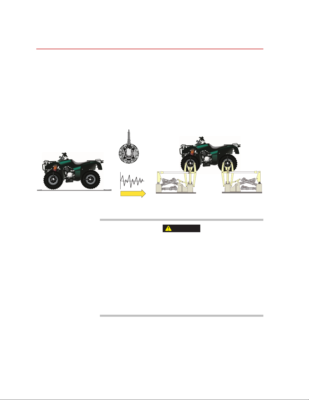
The MTS Spinning Wheel Integrated Force Transducer (SWIFT®) sensor is a
light-weight, easy-to-use transducer that enables you to conduct faster, less
expensive data acquisition and road simulation testing.
The transducer is designed for use on the test track and public roads, as well as in
the test laboratory. It attaches to the test vehicle or an MTS Series 329 Road
Simulator using an adapter and a modified wheel rim.
You can achieve excellent data correlation using the same transducer and vehicle
on the test track or public road and on a road simulator. It is available in various
sizes and materials to fit various vehicle and loading requirements.
Hardware Overview
16
Driving a vehicle with SWIFT sensors mounted on it will change the
handling characteristics of the vehicle.
Driving a vehicle configured in this way on public roads can pose
unexpected dangers to pedestrians and other vehicle traffic.
Only authorized, licensed drivers, who are experienced driving a vehicle with
SWIFT sensors mounted on it, should be allowed to operate the vehicle on public
roads. Drive the vehicle with the SWIFT sensor attached on closed courses only
until you have proper experience.
When driving the vehicle on public roads, you must conform to all local laws and
regulations.
SWIFT 10 ATV Sensors
Page 17

Overview
CAUTION
Parts replacement,
disassembly, and care
The SWIFT sensor assembly, Transducer Interface box, and the accessory
components have no user serviceable parts. These components should not be
disassembled other than as outlined in “Troubleshooting” beginning on page 117.
Do not disassemble the SWIFT sensor, Transducer Interface (TI) electronics,
and accessory components.
The SWIFT sensor, TI electronics, and accessory components are not
intended to be disassembled, other than as outlined in “Troubleshooting”.
Disassembling or tampering with these components may result in damage to the
sensor, loss of watertight seal, and voiding of the warranty.
• The sensor assembly should be returned to MTS annually for recalibration
and inspection.
• Clean the sensor assembly after each use, as described in Maintenance
beginning on page 111, especially if it is exposed to corrosive or abrasive
material, such as salt or sand.
• Read and follow all warnings and cautions affixed to the transducer and in
this manual especially those warnings and cautions that deal with
installation, use, inspection and maintenance of the transducer.
The SWIFT sensor assembly should not:
• Be allowed to strike hard surfaces or objects while driving the vehicle.
• Be driven through grass or brush that is taller than the bottom edge of the
sensor.
• Be exposed to loads that exceed the full scale calibrated ranges. Refer to the
calibration sheets accompanying your transducers.
• Be used if the integrity of the sealed cover has been compromised or the
warning label has been removed.
• Be used if the sensor assembly shows indications of damage (such as dents
on the transducer or slip ring assembly, a bent anti-rotate assembly, etc.).
• Be used if any part of the assembly has been modified without explicit,
written authorization from MTS.
SWIFT 10 ATV Sensors Hardware Overview
17
Page 18
Spinning Applications (Track or Road)
Customer Supplied
Power Supply
Customer Supplied
Data Recorder
Transducer
Interface (TI)
Transducer Signals
Output
Signals
S10-02
Spinning Applications (Track or Road)
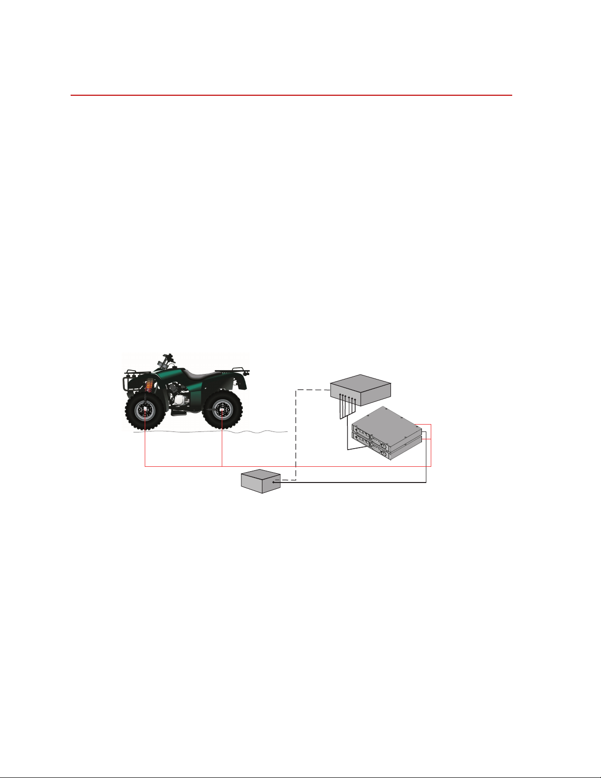
The SWIFT sensor can be used for road load data acquisition (RLDA)
applications:
• Durability
• Noise, Vibration and Harshness (NVH)
• Ride and Handling
• Tire Performance
The transducer is durable enough to withstand harsh road testing and data
acquisition environments. The transducer is splash resistant and suitable for use
in conditions where the test vehicle will encounter occasional standing or running
water, or will be exposed to precipitation. However, it should not be submerged.
In a typical spinning application, the transducer is mounted on a modified rim of
a tire on a test vehicle, as shown in the following figure. The Transducer
Interface (TI), power supply, and data recorder can be securely mounted on a
carriage rack. The TI box should be protected against environmental conditions
(water and mud splashes and dust), and it should not be allowed to be immersed.
18
Hardware Overview
Spinning Application (Track or Road)
SWIFT 10 ATV Sensors
Page 19
Non-spinning Applications (Laboratory)
Power Supply (with 4
connections)
Customer-Supplied
Test Control System
Transducer
Interface (TI)
Transducer Signals
Output
Signals
PC Communication
S10-03
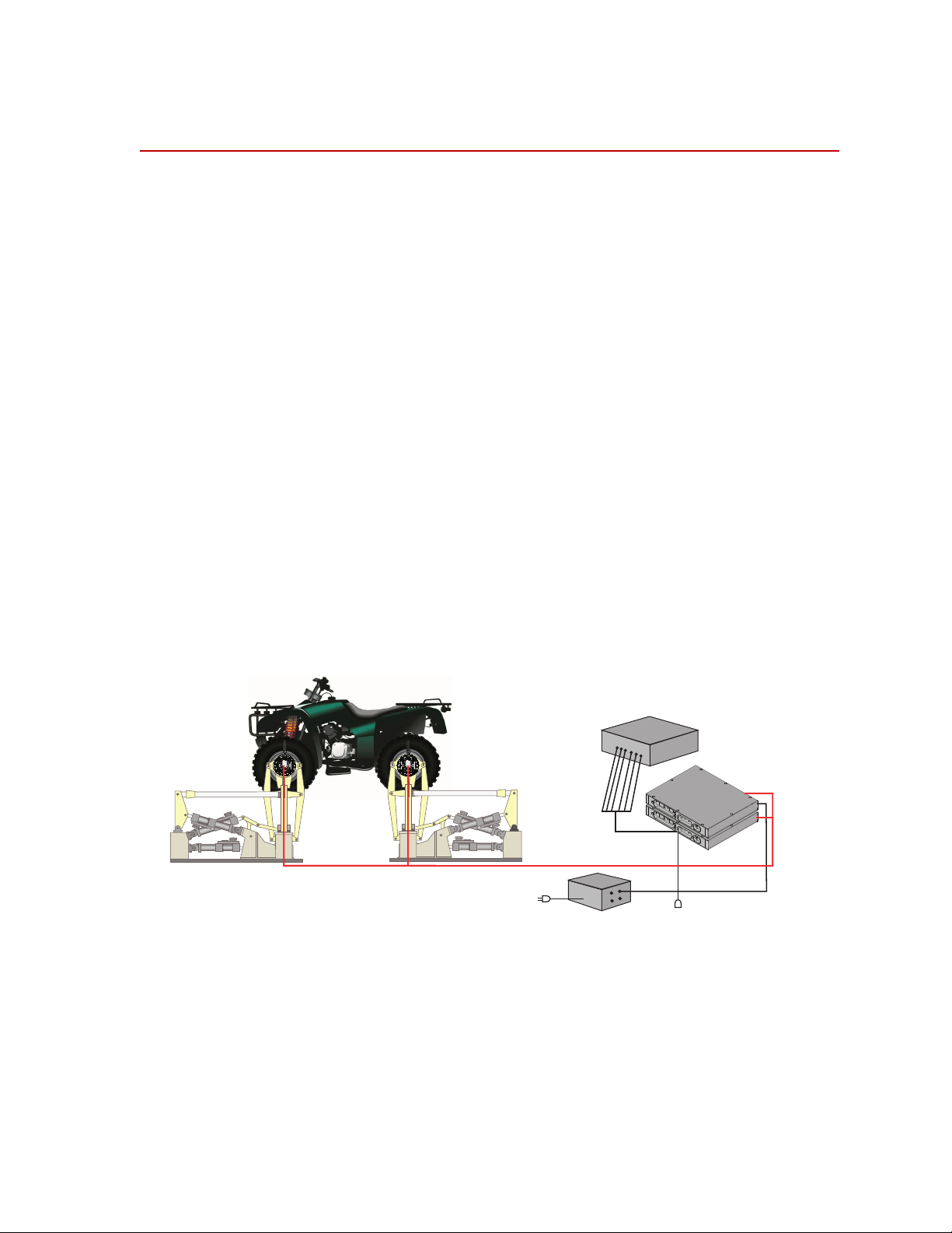
Non-spinning Applications (Laboratory)
The SWIFT sensor can be fully integrated into the simulation process, since it is
an optimal feedback transducer for use with MTS Remote Parameter Control
®
) software. The transducer takes data at points where fixturing inputs are
(RPC
located rather than at traditional instrumentation points along the vehicle’s
suspension. Using the SWIFT sensor saves you instrumentation time, and fewer
iterations are required to achieve good simulation accuracy.
Measuring spindle loads allows engineers to generate generic road profiles.
Generic road profiles are portable across various vehicle models, do not require
new test track load measurements for each vehicle, and eliminate additional
RLDA tasks.
Several of the six loads measured by the transducer directly correlate to the MTS
Model 329 Road Simulator inputs.
The same transducers used to collect road data can be mounted directly in the
wheel adapters of the MTS Model 329 Road Simulator. For durability testing, the
SWIFT sensor can be used for iterations within the RPC process. The SWIFT
sensor should then be removed for the durability cycles, to preserve its fatigue
life. It can be replaced by an adapter plate, available from MTS, to duplicate the
mass and center of gravity of the actual SWIFT sensor. If a SWIFT sensor is to be
used during full durability tests, we suggest using the titanium model, which has
a higher fatigue rating.
®
In a typical non-spinning application, a SWIFT sensor is mounted on a road
simulation test fixture, as shown in the following figure.
Non-spinning Application (Laboratory Simulation)
SWIFT 10 ATV Sensors Hardware Overview
19
Page 20
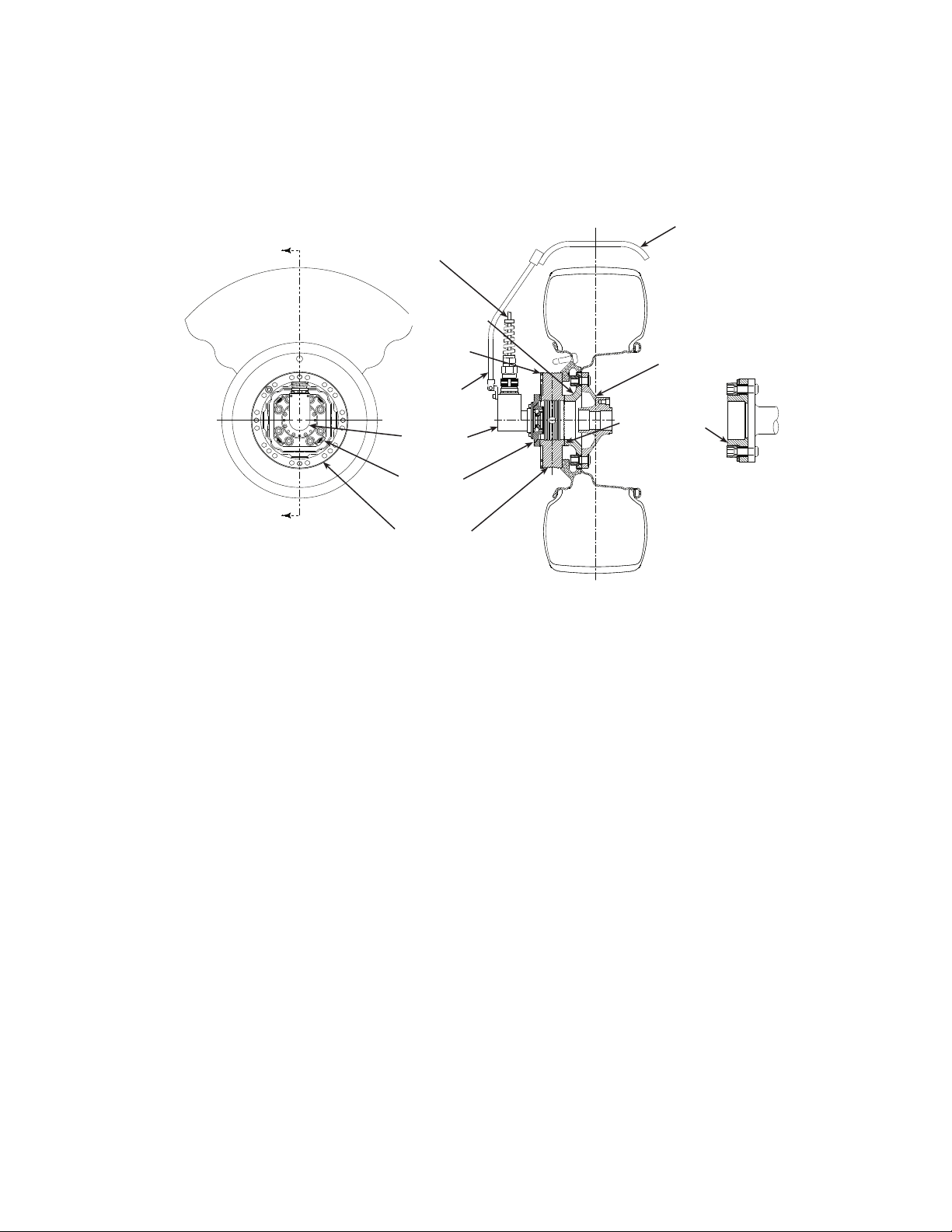
Construction
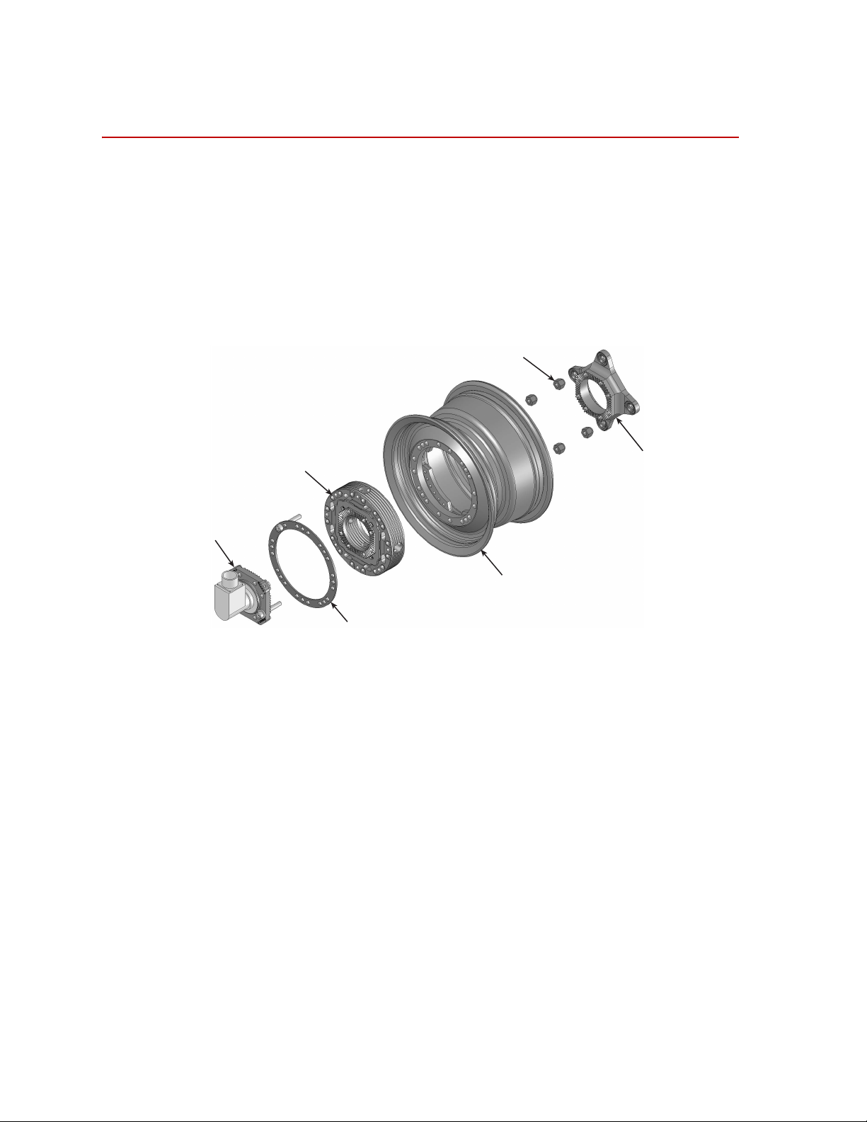
Slip Ring
Bracket
(with encoder)
Washer
Plate
Transducer
Modified Wheel Rim
Lug Nuts
Inner Hub
Adapter
S10-08
Construction
The SWIFT sensor has one-piece construction for outstanding fatigue life, low
hysteresis, and high stiffness. Its compact package has a minimal effect on inertia
calculations, and a minimal dynamic effect on the test vehicle.
The transducer can be used for developing conventional durability tests on the
MTS Model 329 Road Simulator. Normally, the transducer is replaced with an
equivalent wheel adapter after the simulation drive signals are developed and
prior to the start of the test.
The SWIFT sensor includes several mechanical and electrical components.
Hardware Overview
20
Transducer The transducer attaches directly to a modified wheel rim. On the test track
vehicle, the transducer spins with the wheel. On a road simulator, the transducer
attaches directly to an adapter plate on the 329 spindle housing. The slip ring can
be used to accommodate the range of motion of the rear swing arm.The
transducer is available in two materials.
The transducer’s unibody design means there are no multiple parts welded or
screwed together.
The transducer has four beams with strain gages that measure six orthogonal
outputs:
Fx—longitudinal force
Fy—lateral force
Fz—vertical force
Mx—overturning moment
My—acceleration and brake torque
Mz—steering moment
It has onboard conditioning and amplifiers to improve the signal-to-noise ratio.
SWIFT 10 ATV Sensors
Page 21
Construction
Anti-Rotate
Assembly
Slip Ring
and Encoder
Slip Ring
Bracket
Alternate
Spindle Hub
Interface
(for hub piloted
spindle)
Coupling Teeth
Interface
Transducer
Interface
Cable
Washer
Plate
Transducer
Vehicle
Spindle Hub
Inner
Hub Adapter
Anti-Rotate
Mounting Bracket
(customer supplied)
S10-04
Inner hub adapter The inner hub adapter attaches to the inner diameter of the transducer and the
spindle face of the vehicle. The inner hub adapter enables you to maintain the
original position of the tire on the vehicle (the tire will not protrude from the
vehicle) while the transducer is attached to the vehicle.
Components Set Up for Test Track
Slip-ring bracket The slip-ring bracket attaches the slip ring to the transducer. It has internal wiring
that provides excitation power to the strain gage bridges and brings signals out
from the transducer to the slip ring.
Encoder An encoder measures the angular position of the transducer. The SWIFT sensor
encoder is integrated into the slip ring assembly, and counts off “ticks” to
measure the angular position as the wheel rotates. It measures 2048 (512 pulse
quadrature) points per revolution (ppr) with a resolution of 0.18 degrees.
Slip ring The slip ring allows you to output the transducer bridge signals and angular
position to the TI. A transducer data cable attaches from the slip ring to the back
panel of the TI.
Anti-rotate device The anti-rotate device is attached to the slip ring and the vehicle’s suspension (or
other non-rotating point). It is able to move up and down with the vehicle. Its
primary function is to provide a fixed reference point for the angle sensor. Its
secondary function is to prevent the cable from rotating with the wheel and
becoming tangled or breaking.
The slip ring and anti-rotate device are used mainly for road data collection.
Although it can also be used for short periods of time on a road simulator. MTS
does not recommend this use. Due to the extreme fatigue loading characteristics
SWIFT 10 ATV Sensors Hardware Overview
of durability testing on road simulators, we suggest that you either remove the
slip ring assembly before installing the vehicle on a road simulator, or use it only
for iteration passes, then promptly remove it.
21
Page 22

Construction
The anti-rotate device should be configured such that no loading occurs to the
slip ring throughout all loading and suspension travel. This means that when you
attach the anti-rotate device to the vehicle, you must consider all possible motion
of the suspension. The anti-rotate device should not bump against the wheel well
at any time; any jarring of the anti-rotate arm will damage the slip ring. For
steering axles, the anti-rotate bracket must be mounted to part of the unsprung
suspension that steers with the tire, such as the brake caliper. For additional antirotate device mounting recommendations, refer to the Anti-Rotate Customer/
User Assembly drawing at the back of this manual.
Transducer Interface
(TI)
Additional
components
The TI provides power to the transducer and uses previously stored calibration
values to convert the raw transducer signals from the bridge outputs and the
encoder to three force outputs (Fx, Fy, Fz), three moment outputs (Mx, My, Mz)
and an angle output. The force and moment outputs have a value of 10 V full
scale, unless a different full-scale output is requested by a customer. The angle
output is a 0–5 V sawtooth output.
Additional components that are supplied with your SWIFT sensor include
transducer data cables, TI power cable, a SWIFT Transducer Interface Utilities
CD or disk, and the calibration file. MTS can also provide a 12 V DC power
converter for use in the test laboratory.
Hardware Overview
22
SWIFT 10 ATV Sensors
Page 23

Design Features
Flexure isolation The SWIFT sensor has a very stiff outer ring and flexured beam isolation which
Thermal stability The entire sensor is machined from a solid, specially forged billet of high
Construction
render it relatively insensitive to stiffness variations in matings with rims and
road simulator fixtures.
Flexure isolation minimizes thermal expansion stresses. With flexure isolation, if
the inner hub experiences thermal expansion the beams are allowed to expand
out, resulting in lower compressive stress on the beams.
strength titanium or aluminum. The absence of bolted joints permits an efficient
transfer of heat across the sensor structure, minimizing temperature differentials
in the gaged area.
The transducer is designed to accommodate the high temperature environments
that occur during severe driving and braking events. Individual temperature
compensation of each strain gage bridge minimize temperature induced
variations in accuracy. Since minimal electronics reside on the SWIFT sensor, it
can easily tolerate high temperatures. The temperature rating for the SWIFT
sensor is 125° C (257° F) at the spindle hub.
Temperature compensation is done on each bridge for better performance in
transient or non-uniform temperature occurrences.
Low hysteresis The SWIFT sensor has very low hysteresis, since the sensing structure is
constructed with no bolted joints. Micro slippage in bolted joints contributes
most of the hysteresis in highly stressed structures. Hysteresis errors due to
micro-slip at joints can contribute to unresolvable compounding errors in
coordinate transformation of the rotating sensor.
Low noise The SWIFT sensor uses a slip ring rather than telemetry for the transducer output
signals. On-board amplification of the transducer bridges minimizes any slip ring
noise contribution.
Low cross talk The advanced design of the SWIFT sensor means that it has very low cross talk.
The alignment of the sensing element is precision machined. This alignment is
critical to achieving minimum cross talk error between axes and minimum errors
in coordinate transformation (from a rotating to a non rotating coordinate
system). Any small amount of cross talk present is compensated by the TI.
Velocity information Angular output is available from the TI when it is used in the spinning mode with
the encoder. This angular output can be used to calculate wheel velocity. In nonspinning applications, accelerometers can be integrated into the transducer
connector housing.
MTS does not supply any conditioning electronics for accelerometers. Ask your
MTS consultant for more information about this option.
SWIFT 10 ATV Sensors Hardware Overview
23
Page 24
Coordinate System
Fx
Fy
Fz
Mz
Mx
My
Transducer
Interface
Output signals
±10 Volts
Angular
Position
Bridge
Outputs
S10-10
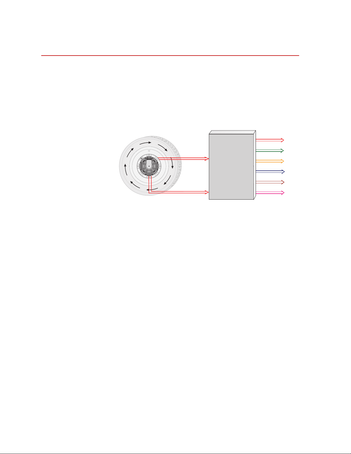
Coordinate System
In the transducer, independent strain gage bridges measure forces and moments
about three orthogonal axes. The signals are amplified to improve the signal-tonoise ratio. An encoder signal measures angular position, which is used to
convert raw force and moment data from the rotating transducer to a vehiclebased coordinate system. The force, moment, and encoder information are sent to
the transducer interface (TI).
The TI performs cross talk compensation and converts the rotating force and
moment data to a vehicle coordinate system. The result is six forces and moments
that are measured at the spindle: Fx, Fy, Fz, Mx, My, and Mz. A seventh
(angular) output is available for tire uniformity information, angular position, or
to determine wheel speed (depending on the data acquisition configuration).
Hardware Overview
24
SWIFT 10 ATV Sensors
Page 25
Coordinate System
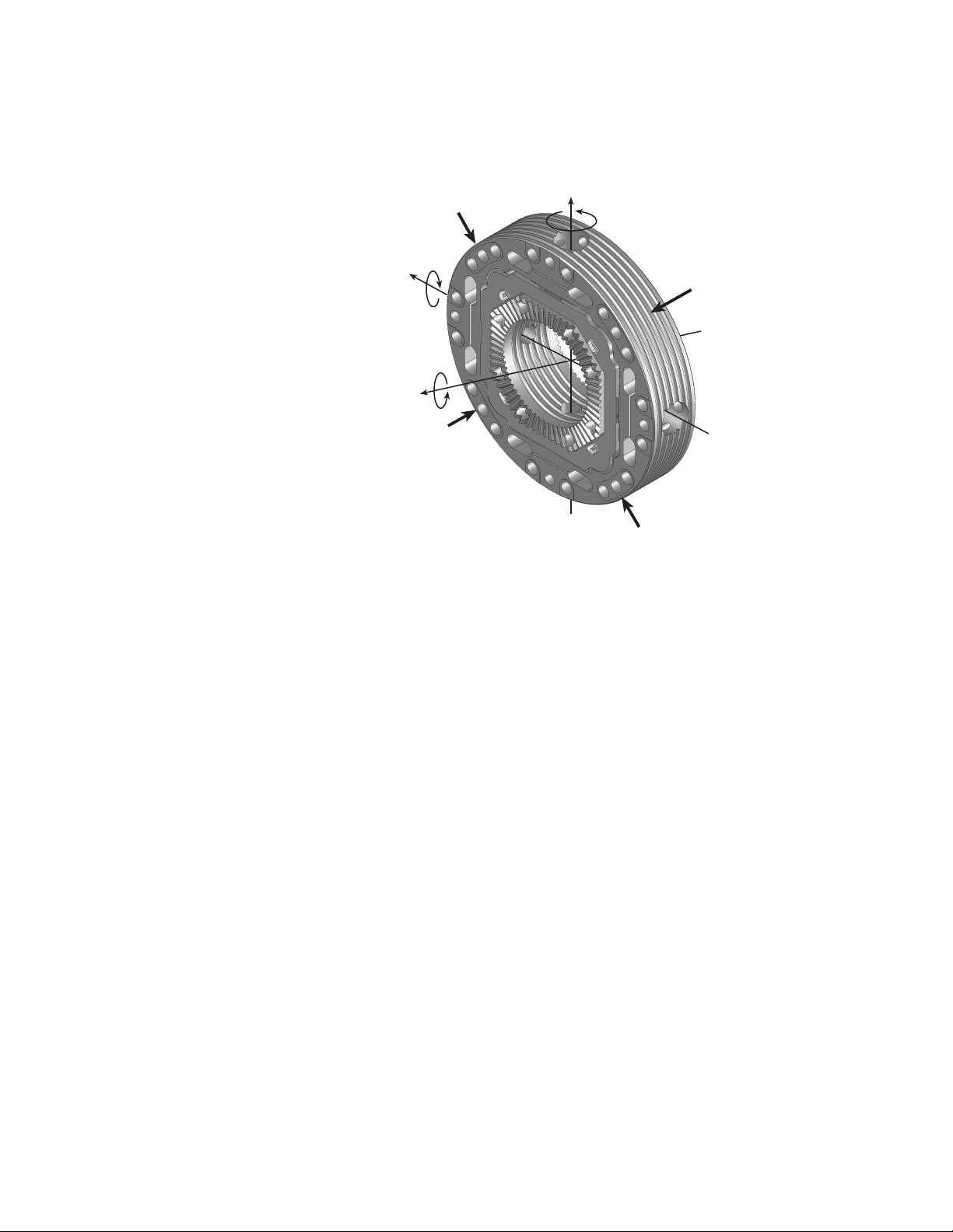
+Fz
+Mz
+Fx
+Fy
S10-09
Forces Acting on Rim-side of Transducer
Hub Adapter
Mounting Side
Rim Flange
Mounting Side
+Mx
+My
The coordinate system shown below was originally loaded into the TI settings by
MTS. It uses the right-hand rule.
The SWIFT coordinate system is transducer-based, with the origin located at the
center of the transducer. Positive loads are defined as applied to the outer ring of
the transducer.
• Vertical force (Fz) is positive up.
• Lateral force (Fy) is positive out of the vehicle.
• Longitudinal force (Fx) follows the right-hand rule, consistent with Fz and
Fy described above.
You can change to the MTS Model 329 Road Simulator convention (lateral load
into the vehicle is always positive) or to any coordinate system by changing the
polarities in the calibration file. For instructions on how to change the coordinate
system polarities, see the chapter, “Setting up the Transducer Interface”.
SWIFT 10 ATV Sensors Hardware Overview
25
Page 26

Specifications
Specifications
SWIFT 10 ATV Transducer Performance (part 1 of 2)
P
ARAMETER SPECIFICATION
Use
SWIFT 10 ATV (aluminum) for:
SWIFT 10 ATV (titanium) for:
Maximum usable rpm
Maximum speed
Shock resistance, each axis
Fits rim size (usable range)
Number of Lug nuts accommodated
Hub bolt circle diameter accommodate
Wheel stud size accommodated
Input voltage required
Input power required per transducer
Output voltage ± full scale calibrated load
SAE J328
Rated load capacity
Bending moment
Full scale calibrated ranges
Resolution
Performance accuracy
Nonlinearity
Hysteresis
Modulation
Cross talk
Maximum operating temperature
Assembly Weight – single wheel
Transducer
Aluminum hub adapter/spacer
Slip ring assembly
Modified aluminum rim
Lug nuts
Outer steel washer plate
Attached fasteners
Total
#
‡
§
**
low weight, high sensitivity, lower measured forces
1.45 kN•m (12 869 lbf•in)
Consult the calibration range sheet that accompanies each
transducer
high fatigue life, longer durability, higher loads
2,200
250 kph (155 mph)
150 G
7-12 inch
*
4
All
All
9–30 V DC
7 Watts maximum (22 Watts typical)
†
±10 V
Aluminum
2.5 kN (550 lbf)
Titanium
4.2 kN (925 lbf)
4.76 kN•m (42117 lbf•in)
Infinite
1.0% full scale
0.50% full scale
≤5.0% reading
1.5% full scale
125°C (257°F
1.4 kg (3.0 lb)
0.5 kg (1.0 lb)
0.5 kg (1.1 lb)
2.4 kg (5.3 lb)
0.1 kg (0.2 lb)
0.2 kg (0.4 lb)
0.8 kg (1.8 lb)
5.8 kg (12.8 lb)
2.0 kg (4.5 lb)
0.5 kg (1.0 lb)
0.5 kg (1.1 lb)
2.4 kg (5.3 lb)
0.1 kg (0.2 lb)
0.2 kg (0.4 lb)
0.8 kg (1.8 lb)
6.5 kg (14.3 lb)
Hardware Overview
26
SWIFT 10 ATV Sensors
Page 27

Specifications
SWIFT 10 ATV Transducer Performance (part 2 of 2)
P
ARAMETER SPECIFICATION
Output connector type
Auto shunt calibration
* Contact MTS for other rim sizes. Larger diameter rims can be used, provided that overall clearance from
brake calipers and suspension components is maintained.
† Load impedance >1 k
‡ Half axle rated capacity per SAE J328.
§ Moment fatigue-rated for 100,000 cycles.
# Each SWIFT sensor is calibrated on an MTS calibration machine. MTS provides complete documentation
of calibration values for each SWIFT unit
** Measured at the spindle hub.
Ω; 0.01 µF (maximum) load capacitance.
D-shell or BNC via adapter
On vehicle or laboratory test rig.
SWIFT 10 ATV Sensors Hardware Overview
27
Page 28
Specifications
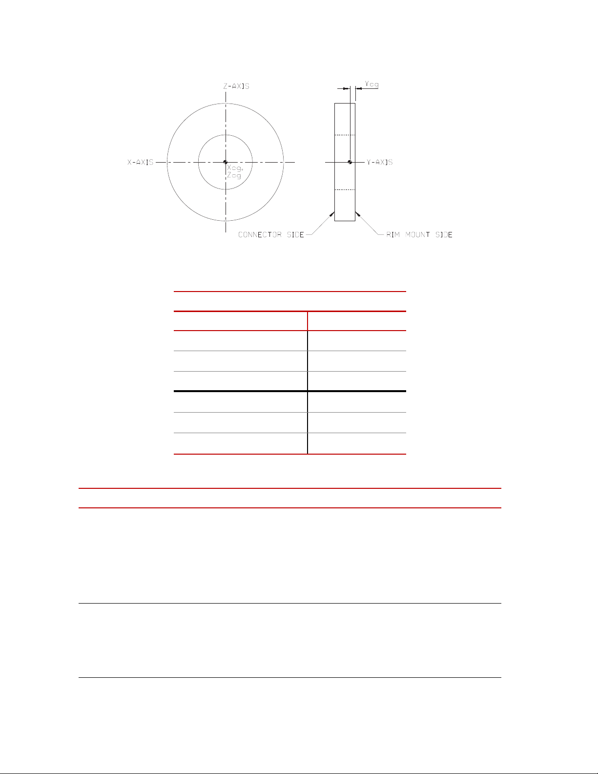
Transducer Center-of-Gravity
Transducer Center-of-Gravity and Inertia Specifications
M
ATERIAL
ALUMINUM TITANIUM
X
0.0 mm 0.000 in 0.0 mm 0.000 in
cg
Y
18.0 mm 0.710 in 18.0 mm 0.710 in
cg
Z
0.0 mm 0.000 in 0.0 mm 0.000 in
cg
I
xx
26 kg·cm29 lbm·in
I
yy
50 kg·cm217 lbm·in280 kg·cm227 lbm·in
I
zz
26 kg·cm29 lbm·in
2
42 kg·cm214 lbm·in
2
42 kg·cm214 lbm·in
Transducer Interface (part 1 of 2)
P
ARAMETER SPECIFICATION
Physical
Height
Width
Depth
Weight
Rack Mounting Kit
28 mm (1.100 in)
213 mm (8.375 in)
171 mm (6.750 in.)
0.907 kg (30 oz)
Optional
2
2
2
*
Environmental
Ambient temperature
Relative humidity
Protection
Hardware Overview
28
0° C (32° F) to 50° C (122° F)
0 to 90%, non-condensing
IP64 (complete dust protection, projected water
from all directions)
SWIFT 10 ATV Sensors
Page 29

Transducer Interface (part 2 of 2)
P
ARAMETER SPECIFICATION
Power Requirements
Input voltage
Fuses
10–28 V DC
Internal thermal, self-resetting
Specifications
Power Consumption
4 Watts maximum without transducer or encoder
6 Watts typical with transducer and encoder at 12
V DC
Angular velocity
Encoder limit
Processing limit
Encoder resolution
2,200 rpm maximum
10,000 rpm maximum
2048 counts per revolution
(512 pulses with quadrature)
Time delay (encoder tick to main output stable)
Transducer cable length
Analog outputs
Vol tag e
150 µs (typical)
100 ft maximum
±10 V range† (force and moment outputs)
0–5 V sawtooth (angle output)
Capacitive load
Current
Noise at output, with typical gains
0.01 µF maximum
2 mA maximum
7 mVpp, DC - 500 Hz (typical)
15 mVpp, DC - 500 Hz (maximum)
* Add 25.4 mm (1.0 in) for ground lugs.
† Standard from MTS. Other full scale voltages can be evaluated and may be provided at special
request.
SWIFT 10 ATV Sensors Hardware Overview
29
Page 30

Calibration
Calibration
Each transducer is calibrated by MTS before shipment. The transducer and TI
may be returned to MTS for repair and recalibration as required.
Calibration is performed at MTS on a special fixture that is capable of applying
multiple loads to the transducer. During calibration, raw signals are measured.
The calibration gains and cross talk compensation values are computed from this
raw data. These gains are recorded in a calibration file.
A unique calibration file is supplied for each transducer. The serial number of the
TI associated with the transducer is listed at the top of the calibration file. A label
with the serial number of the TI box (and the SWIFT sensor with which it was
originally calibrated) is attached to the back of each TI box.
The calibration file is loaded into the TI non-volatile memory by MTS before the
transducer is shipped. A copy of the file is also provided on a diskette.
MTS verifies the calibration by applying loads to the transducer, measuring the
main outputs and checking for accuracy. Final calibration reports are provided
with each transducer.
Shunt calibration At the end of the calibration process, a shunt calibration is performed. During a
shunt calibration, a resistance is introduced into the bridge circuit. The difference
between the shunted and unshunted voltage is the delta shunt reference value for
each bridge. That value is saved in the calibration file, which is downloaded from
a PC or laptop computer and stored in non-volatile memory in the TI.
At any time afterward, pressing the Shunt button on the front of the TI causes
each of the strain gage bridges to be shunted in sequence, and the measured shunt
voltage (delta shunt measured value ) is compared to the reference value.
An acceptable tolerance range is also loaded into the TI memory during system
calibration. One tolerance value is used for all bridges. This value is loaded as a
percentage of allowable deviation from the delta shunt values. For example, if the
FX1 bridge has a shunt delta reference value of –3.93, and the tolerance is set at 2
(percent), the acceptable range for the measured value would be –3.85 to –4.01.
Hardware Overview
30
SWIFT 10 ATV Sensors
Page 31

Calibration
When you press the Shunt button, the associated Shunt indicators toggle while
the shunt is in progress. As the TI automatically switches through the series of
bridges, it verifies that the outputs are within the accepted tolerance range. If all
bridge shunt values fall within the tolerance range, the Shunt indicators on the
front panel will go off (after several seconds). If any bridge fails the shunt test,
the red, fail indicator lights, indicating that the shunt calibration has failed. The
fail indicator remains lit until a shunt check passes or until you cycle power off
and on. Use the TI2STATUS utility to get more detailed information about the
shunt failure.
ShuntTolerance=2
FX1ShuntDeltaRef=-1.379
FX2ShuntDeltaRef=-1.386
FY1ShuntDeltaRef=-1.381
FY2ShuntDeltaRef=-1.378
FY3ShuntDeltaRef=-1.382
FY4ShuntDeltaRef=-1.381
FZ1ShuntDeltaRef=-1.380
FZ2ShuntDeltaRef=-1.380
FX1ShuntDeltaMeas=-1.378
FX2ShuntDeltaMeas=-1.386
FY1ShuntDeltaMeas=-1.380
FY2ShuntDeltaMeas=-1.379
FY3ShuntDeltaMeas=-1.382
FY4ShuntDeltaMeas=-1.382
FZ1ShuntDeltaMeas=-1.385
FZ2ShuntDeltaMeas=-1.382
Checking the
calibration
Example of Calibration File Shunt Data
The above example shows shunt data from the calibration file. This data may be
transferred, using the TI2XFER program, from the transducer interface memory
to a computer or from a computer to the transducer interface memory. Note that
items marked ShuntDeltaMeas are uploaded from memory, but not downloaded
from the computer.
For more information on TI2XFER, see the chapter, “Software Utilities”.
You can check the calibration of a transducer at any time by pressing the Shunt
switch (described earlier). Subsequent shunt commands compare the current
feedback values against those stored in the TI. You may set the tolerance values
for each TI by editing the calibration file. See the chapter, “Setting up the
Transducer Interface”, for instructions.
SWIFT 10 ATV Sensors Hardware Overview
31
Page 32

Transducer Interface
Fx
Fy
Fz
Mz
Mx
My
Transducer
Interface
Output signals
(±10 Volts)
Angular
Position
Bridge
Outputs
Transducer bridge output
signals and encoder
angular position signal are
sent through slip ring
Transducer Interface
converts signals to non-
spinning vehicle coordinates,
applies calibration gains and
cross talk compensation
Force, moment, and
angle analog signals
are output from
Transducer Interface
q
Angle signal
(05 Volts)
S10-05
Transducer Interface
The TI performs cross talk compensation, transforms the loads from a rotating to
a non-rotating coordinate system, and produces an analog output signal suitable
for any data recorder.
Cross talk
compensation
Cross talk occurs when a force is applied to one axis, but a non-real force is
measured on another axis. The SWIFT sensor design has very low inherent cross
talk. The TI compensates for cross talk by subtracting cross talk values measured
during calibration.
Signal conditioning The TI is specifically designed to be used for both spinning and non-spinning
applications. The TI performs signal conditioning and communications
functions. The output from the TI is a high-level signal suitable for input into a
multichannel data recorder or an MTS Automated Site Controller (ASC).
32
Hardware Overview
SWIFT 10 ATV Sensors
Page 33

Transducer Interface
Fx1
Fx2
Fy1
Fy2
Fy3
Fy4
Fz1
Fz2
Fx
Fy
Fz
Mx
My
Mz
Geometric
Matrix
Zero and
Scaling
q
Cross
Coupling
Matrix
Rotational
Transformation
q
Inputs Outputs
Transducer Interface Functions
S50-011
The TI transforms eight inputs (amplified bridge signals) into three forces and
three moments by the following process:
• Applying a zero offset and scaling the signals
• Using a geometric matrix to transform the signals into three forces and three
moments in the transducer reference frame
• Using a cross-coupling matrix calculation to scale and sum the individual
signals into each output
• In spinning applications, using a rotational transformation to put the forces
and moments into a stationary reference frame
The TI conditions the transducer signals, producing seven analog output signals
proportional to the following values:
• Longitudinal force (Fx)
• Lateral force (Fy)
• Vertical force (Fz)
• Overturning moment (Mx)
• Driving/Braking moment (My)
• Steering moment (Mz)
• Angle output (θ)
Analog signals The force and moment signals are output from the TI in the form of ±10 V
scale analog signals. These signals can be used by most data acquisition systems.
The angle output is an analog voltage that is proportional to angular position. At
0° the output is 0 V. At 360°, the output is 5 V.
1
full
1. Standard from MTS. Other full-scale output voltages can be evaluated and may be
provided at special request.
SWIFT 10 ATV Sensors Hardware Overview
33
Page 34

Transducer Interface
0 360°
5V
0° 360°
q
Angle
Output
1 rev = 360°
S20-10
The angle output for a tire rotating at constant velocity can be represented by the
following illustration:
Although you may not routinely use it, the angle output information is available
for tasks such as tire uniformity testing and troubleshooting. You may also
calculate angular velocity by measuring the frequency of the angle output signal.
If using the sawtooth angle output for analysis or computing velocity, care should
be taken when setting the data acquisition to avoid filter-induced ringing or
attenuation of the sawtooth output.
Communications The TI uses USB 2.0 for communication. The MTS supplied USB drivers must
be installed on each computer you connect to the TI.
Hardware Overview
34
SWIFT 10 ATV Sensors
Page 35

TI Front Panel
Power button and
Indicator and Fail
Indicator
Shunt button and Indicators
Zero button and Indicators
J5 USB Connector
J4 I/O Connector
Transducer Interface
Transducer Interface Front Panel
Power button and
Indicator
Shunt button and
indicators
Zero button and
indicators
The power button turns power on and off. Pressing and holding the button turns
on power and initializes the TI. During initialization, all indicators turn on
momentarily. When initialization is complete, all indicators will turn off with the
exception of the green Power indicator.
Pressing this button performs a shunt calibration (shunt cal) of the transducer.
You do not need to hold the button in continuously, only until the Shunt
indicators light up (indicating that the TI has started the shunt cal). The two
indicators will alternately toggle on and off as the TI sequences through the shunt
calibration of each bridge.
Before you perform a shunt cal, check that the appropriate shunt reference value
and error tolerance have been downloaded (these values are normally loaded
during system calibration, and are referred to as the shunt delta cal values).
A shunt calibration will determine the current delta values by measuring the
bridges unshunted and shunted values, and then compare these values to the
previously loaded calibration values.
If the measured values are outside of an acceptable tolerance the red status
indicator under the Power indicator with light.
Note The state of the shunt cal check is cleared at power-up, so the shunt cal
should be performed when the system installation is in question.
The zero button is used to zero the transducer inputs. When you press the button,
the TI executes the ZeroAlgorithm that you specify in the calibration file (see
following illustration).
J5 USB connector The USB connector is a standard USB 2.0 type B connector for output to a laptop
or PC with the correct drivers installed.
J4 I/O connector Not used at this time.
SWIFT 10 ATV Sensors Hardware Overview
35
Page 36

Transducer Interface
J3 Transducer Connector
J2 Output Connector
J1 Power Connector
TI Rear Panel
Transducer Interface Rear Panel
J1 Power connector Connect a power cable from the external power source.
J2 Output connector The J2 Output connector provides the conditioned sensor outputs that can be
connected to a data acquisition or test control system.
J3 Transducer
connector
Connect the data cable from the transducer slip ring to the Transducer Connector.
36
Hardware Overview
SWIFT 10 ATV Sensors
Page 37

Interfacing with RPC
The SWIFT sensor is directly compatible with the MTS Remote Parameter
Control (RPC) simulation software. The SWIFT system produces outputs that
directly correspond to the uncoupled spindle forces that the MTS Model 329
Road Simulator applies to the vehicle. Traditional instrumentation techniques
provide coupled suspension loads data. Using the SWIFT sensor, the RPC
simulation software needs to apply less correction to obtain the road simulator
drive signals. Fewer iterations are required to recreate the measured loads.
You must ensure that the full scale value for your data recorder and the MTS
electronics match. MTS electronics are typically set at ±10 V full scale, while
some data recorders are ±5 V full scale.
The SWIFT sensor is calibrated for ±10 V full scale. To recompute the TI gains
for ±5 V full scale, a verification pass must be run or the calibration will not be
traceable. Upon special request, MTS can evaluate and may provide calibration
for ±5 V or other full scale voltages.
Interfacing with RPC
SWIFT 10 ATV Sensors Hardware Overview
37
Page 38

Interfacing with RPC
Hardware Overview
38
SWIFT 10 ATV Sensors
Page 39

Software Utilities
Contents Introduction 40
TI2STATUS - Transducer Interface Status 41
TI2XFER - Transducer Interface Transfer 43
TI2SHUNT - Transducer Interface Shunt 45
Setting Up Shunt Calibration Reference Values 48
Error Messages 49
SWIFT 10 ATV Sensors Software Utilities
39
Page 40

Introduction
Introduction
The SWIFT utility programs in this distribution are for Win32 Operating
Systems (Windows 2000 and XP). They are designed to be run from the
Command Prompt or MSDOS Shell. However, it is possible to create a shortcut
to run the programs. If launched from a shortcut the application window may
close immediately when the application terminates making it impossible to see
any error messages. The Command Prompt application is usually found in
Start–>Programs–>Accessories but the actual location depends on the version
of your operating system.
To run a SWIFT utility program
• Copy it to your computer. For example, create the folder
the executables (*.exe) to that folder.
• Launch Command Prompt
• Change the working directory to where you copied the executables: cd bin.
This step can be eliminated if you set up the PATH environment variable to
include the directory where you copied the SWIFT utility executables.
• Type the name of a SWIFT utility program providing the necessary
command line arguments, for example:
from the TI box. Then select the desired function, for example:
to upload settings from the TI box. If no command line arguments are
provided the program will display a simple help message. This is helpful if
you forget the order of the command line arguments.
1
ti2xfer to transfer settings to or
C:\bin and drag
2
Choice 1
Software Utilities
40
1. You may want to change the layout properties for the Command Prompt
window to display a larger area or to increase the screen buffer size. Within
Command Prompt, select Properties and the Layout tab to modify the
screen buffer size or window size.
2. In Windows 2000 and Windows XP, the environment variables can be
changed at
Start–>Settings–>Control Panel–>System. Click on the Advanced tab,
and the Environment Variables button. The path is a system variable.
Adding
string will cause Command Prompt to search that directory for
applications.
;c:\bin, or whatever directory name you used, to the end of the
SWIFT 10 ATV Sensors
Page 41

TI2STATUS - Transducer Interface Status
TI2STATUS - Transducer Interface Status
This program gets status information from the SWIFT Transducer Interface (TI)
when the TI has encountered a problem and the red failed indicator is lit. You can
use this program to easily interpret the error. For certain errors this program may
provide additional information.
Syntax ti2status
The following is an example of the ti2status command report:
Example
C:\bin>ti2status
SWIFT Mini TI status (Version 1.3)
Fatal error: NONE
Boot Loader version: 1
FPGA version: 10
Firmware version: 24
Zero: Good
Fx1 Shunt: Good
Fx2 Shunt: Good
Fy1 Shunt: Good
Fy2 Shunt: Good
Fy3 Shunt: Good
Fy4 Shunt: Good
Fz1 Shunt: Good
Fz2 Shunt: Good
Calibration data is: Good
Unit serial number: 02036413
Description of TI2STATUS Indications
Fatal Error: Provides an indication that the CPU is unable to run. The message indicates the
possible reason (see, “Error Messages,” on page 49 for a list of the possible
errors).
Boot Loader version: The boot loader is a program that verifies that the main program is complete. The
version number is a reference for use by service personnel (see, “Error
Messages,” on page 49 for a list of the possible errors).
FPGA version: Identifies the version of the functions programmed in the field programmable
gate array. The version number is a reference for use by service personnel.
Firmware Version: Displays the version of the software installed in the TI. This software is stored in
flash memory and if needed can be upgraded in the field by an MTS service
engineer.
SWIFT 10 ATV Sensors Software Utilities
41
Page 42

TI2STATUS - Transducer Interface Status
Zero: Indicates whether the transducer zeroing was successful or not (see, “Error
Messages,” on page 49 for a list of the possible errors).
F## Shunt: Indicates the status of shunt test for each bridge (see, “Error Messages,” on page
49 for a list of the possible errors).
Calibration data is: Indicates the condition of the calibration data (see, “Error Messages,” on page 49
for a list of the possible errors).
Unit serial number: Displays the serial number of the TI box
Software Utilities
42
SWIFT 10 ATV Sensors
Page 43

TI2XFER - Transducer Interface Transfer
TI2XFER - Transducer Interface Transfer
This program is used to read the current settings in the TI and save them to the
computer (upload) or write the values from a calibration file on the computer to a
TI (download).
Syntax ti2xfer
Example The following is an example of the ti2xfer command:
C:\bin>ti2xfer
SWIFT Mini TI transfer (Version 1.0)
Upload and download settings
0...Exit
1...Upload settings from TI box
2...Download settings to TI box
Choice? 1
Filename? sample.cal
0...Exit
1...Upload settings from TI box
2...Download settings to TI box
Choice? 0
File Format The file used with commands contains a header and version number, and a list of
parameters. Transducer calibrations can be uploaded and saved individually. If a
test needs to be rerun at a later date but the original transducer is not available,
another transducer can be used by downloading its calibration information.
The header must be the first thing in the file, and it must be in the form:
[SWIFT]
Following the header is a list of parameter settings. The syntax is:
ParamName=ParamValue
The following rules apply:
Tabs and spaces are allowed.
The parameters can occur in any order
Names are case insensitive. If a parameter name is not recognized, an error
will be reported, and further processing will be stopped.
If an error causes the program to abort while downloading, any parameters
prior to the error will have been successfully downloaded because
parameters are downloaded as they are read.
SWIFT 10 ATV Sensors Software Utilities
43
Page 44

TI2XFER - Transducer Interface Transfer
CAUTION
CAUTION
Make important files (such as those containing calibration data) read-only
after uploading.
If not protected, important data may get overwritten.
Make important files read-only. Make backups of important data.
Check force and moment output signals after downloading new settings.
Downloading new settings may affect Transducer Interface outputs.
After downloading new settings, force and moment output signals should be
monitored to check basic system operation.
More about TI2XFER
files
The calibration files created by TI2XFER are plain text files that can be read by
Microsoft Notepad or WordPad (see the example calibration file on page 55). In
general, use a common extension such as “.cal” to help identify the files, but that
is not required. The settings files contain both configuration settings and
calibration settings. As a general rule parameters that begin with K are
calibration gains and should not be edited.
Whenever downloading settings, make sure the file is for the transducer
connected to the SWIFT Transducer Interface. Usually the filename for the
settings contains the serial number for the transducer. If settings for one
transducer are used with another they will not be accurate. Because the TI is
calibrated by itself, calibration settings for a given transducer can be used with
any TI, however, some calibration methodologies require the transducer, cable
and TI to be used as a calibration set (end-to-end calibration).
The serial number in the TI2XFER settings file is the serial number of the TI that
the settings were first uploaded from.
The bridge and angle zero values will change whenever a zero is activated by
pressing the TI front panel Zero button. Therefore, after a zero is performed the
zero values uploaded will not match those downloaded.
Software Utilities
44
SWIFT 10 ATV Sensors
Page 45

TI2SHUNT - Transducer Interface Shunt
TI2SHUNT - Transducer Interface Shunt
This program is a utility with various functions related to shunts. The SWIFT
system includes the ability to connect a shunt resistor across each of the resistive
bridges in the transducer. This shunt function can be used as a simple verification
that the SWIFT system is working normally. Shunt verification activates the
shunts and compares the results to those recorded during calibration. While this
does not guarantee the transducer is still in calibration, it provides some level of
confidence it is working normally. If the shunt results differ significantly from
those recorded during calibration the SWIFT system should be evaluated for
possible problems.
Syntax ti2shunt
Example
C:\bin>ti2shunt
SWIFT Mini TI Shunt (Version 1.0)
0...Exit
1...Read current shunt status
2...Set the TI shunt tolerance
3...Scan inputs with shunts
4...Command a shunt cal
5...Set references to last measured
Enter choice: 1
The Shunt Main Menu options are described in the following paragraphs.
Option 0 Use this option to exit the program.
Option 1 Use this option to read the last measured shunt values, the reference values, and
the shunt status.
Note The shunt status is not maintained over power cycles, so it is only valid if
the shunt is executed after power is applied. Refer to, “Error Messages,”
on page 49.
The following is typical of what is displayed when this selection is made:
Enter choice: 1
FX1 Ref: 0.854 Measured: 0.854 Status: Good
FX2 Ref: 0.855 Measured: 0.855 Status: Good
FY1 Ref: 0.857 Measured: 0.857 Status: Good
FY2 Ref: 0.858 Measured: 0.857 Status: Good
FY3 Ref: 0.856 Measured: 0.856 Status: Good
FY4 Ref: 0.857 Measured: 0.856 Status: Good
FZ1 Ref: 0.856 Measured: 0.856 Status: Good
FZ2 Ref: 0.856 Measured: 0.855 Status: Good
SWIFT 10 ATV Sensors Software Utilities
45
Page 46

TI2SHUNT - Transducer Interface Shunt
Option 2 Use this to set the shunt tolerance. When selected, the following is displayed:
Enter choice: 2
The current shunt tolerance is 2%
Enter new shunt tolerance in percent?
Option 3 Use this option to apply a shunt to each bridge individually, read the output of the
bridge, compare the result with the value stored in the Transducer Interface and
display the difference each bridge. See the table on the next page. The shaded
fields are the bridge being shunted. The actual sequence depends on the
transducer wiring. Note that this option does not update the shunt measured
values or error status.
Software Utilities
46
SWIFT 10 ATV Sensors
Page 47

Enter choice: 3
Unshunted:
Shunted1:
Differ1:
TI2SHUNT - Transducer Interface Shunt
FX1 FX2 FY1 FY2 FY3 FY4 FZ1 FZ2
0.00050 0.00042 0.00017 -0.00050 -0.00005 -0.00033 -0.00025 0.00000
0.85475 0.00008 -0.00017 -0.00050 0.00028 -0.00033 -0.00025 0.00000
0.85424 -0.00033 -0.00033 0.00000 0.00033 0.00000 0.00000 0.00000
Unshunted:
Shunted2: 0.00050 0.00042 0.85675 -0.00117 0.00028 -0.00000 0.00008 0.00000
Differ2: 0.00033 0.00033 0.85725 0.00100 -0.00033 0.00033 0.00000 0.00000
Unshunted:
Shunted3: 0.00050 0.00008 -0.00017 -0.00017 0.00062 -0.00000
Differ3: 0.00000 0.00000 -0.00033 0.00033 0.00067 0.00000
Unshunted:
Shunted4: 0.00050 0.00008 -0.00017
Differ4: 0.00033 0.00000 0.00033
Unshunted:
Shunted5: 0.00050 0.85557 -0.00017 -0.00050 -0.00005 -0.00033 0.00042 0.00000
Differ5: -0.00033 0.85582 0.00000 -0.00033 -0.00067 0.00000 0.00033 -0.00033
Unshunted:
Shunted6: -0.00017 0.00042 0.00017 -0.00017
Differ6: -0.00067 0.00033 0.00000 0.00033
Unshunted:
Shunted7: 0.00084 0.00008 0.00050 -0.00050 -0.00005 -0.00033 0.00008
Differ7: 0.00033 -0.00033 0.00067 0.00033 0.00000 0.00000 0.00000
0.00017 0.00008 -0.00050 -0.00117 0.00062 -0.00033 0.00008 0.00000
0.00050 0.00008 0.00017 -0.00050 -0.00005 -0.00000 0.00042 0.00000
0.85620 -0.00033
0.85579 -0.00033
0.00017 0.00008 -0.00050 -0.00084 -0.00005 -0.00000 0.00075 -0.00033
0.85747 -0.00005 -0.00033 0.00008 0.00000
0.85831 0.00000 -0.00033 -0.00067 0.00033
0.00084 -0.00025 -0.00017 -0.00017 0.00062 -0.00033 0.00008 0.00033
0.00050 0.00008 0.00017 -0.00050 -0.00038 -0.00000 0.00008 0.00033
0.85614 -0.00033 -0.00025 -0.00033
0.85653 -0.00033 -0.00033 -0.00067
0.00050 0.00042 -0.00017 -0.00084 -0.00005 -0.00033 0.00008 0.00000
0.85510
0.85510
Unshunted:
Shunted8: -0.00017 0.00008 0.00017 -0.00050 0.00028 0.85610 0.00008 0.00000
Differ8: -0.00033 0.00000 0.00000 0.00033 0.00033
0.00017 0.00008 0.00017 -0.00084 -0.00005 -0.00000 0.00008 0.00067
0.85610 0.00000 -0.00067
Option 4 Use this option to command a Shunt Cal in the Transducer Interface. This is the
same as pressing the Shunt button on the front panel of the TI. A period is
displayed on the screen for every change in the shunt state. This gives you a
quick view of the progress.
Option 5 A valid shunt calibration should be performed prior to executing this command.
This option allows an easy means of setting the Shunt Calibration Reference
values after calibration. After this option has executed, the file that was written
can then be downloaded (using TI2XFER option 2). Downloading the file will
set the Shunt Reference values to the last measured values, so that subsequent
Shunt Calibrations should pass when the SWIFT system is setup properly, and
fail when not setup properly.
Note This menu choice should only be used by qualified service personnel.
SWIFT 10 ATV Sensors Software Utilities
47
Page 48

TI2SHUNT - Transducer Interface Shunt
Setting Up Shunt Calibration Reference Values
The ti2shunt utility provides all of the necessary functions for setting up a
Transducer Interface with valid Shunt Cal Reference values.
Note This procedure should only be performed by qualified service personnel.
Before running the ti2shunt utility, connect the Transducer cable from the
SWIFT TI to the SWIFT Transducer Assembly. Power up the SWIFT TI and wait
for the red Fail indicator on the TI front panel to go out (this indicates that the TI
is ready).
Note that it is not necessary to perform a System (Transducer) Zero prior to the
Shunt Cal.
Procedure 1. Launch the ti2shunt utility.
2. Using Option 2, enter the desired shunt tolerance.
3. Using Option 4, command a shunt cal, and wait for it to complete. This
causes the TI to apply and measure each shunt delta. These measured values
will be written as the Cal Reference values. The Shunt indicator on the TI
front panel should not blink (blinking indicates that the shunt cal
verification failed).
4. Using Option 1, read the current shunt parameters. It is not necessary to
save these to a file. Review the measured values and verify that they are
correct.
5. Using Option 5, write the last shunt measurements to a parameter file. This
sets up a file that contains the eight Set Shunt Cal Reference commands,
with the last measured values as the values for the commands. This step
does not download the values, but forces the generation of a shunt cal
reference parameter file.
Write down the filename that is generated, as it will be required later.
6. Using TI2Xfer option 2 to download the shunt parameters from a file to the
TI. Enter the filename used in Option 5 (Step 5). The tishunt utility then
downloads the shunt cal reference values to the TI. These values are written
into non-volatile memory within the TI, and are automatically restored
whenever the TI is powered up.
7. Using Option 4, command another shunt cal, and wait for it to complete.
This provides a verification, showing that the values downloaded are valid.
The Shunt indicators on the TI Front Panel should toggle indicating the shunt
calibration is in process.
Software Utilities
48
SWIFT 10 ATV Sensors
Page 49

Error Messages
When a SWIFT utility encounters an error, the red failed indicator on the TI front
panel lights. Run the TI2STATUS program to identify the cause of the error.
Following is a list of possible error messages:
• Fatal Errors
Error Messages
NONE
Failed command port initialize
Failed I2C (integrated-integrated-circuit) initialize
Failed non-volatile memory initialize
Failed comput module initialize
Failed ADC (analog-to-digital converter) initialize
Failed DAC (digital-to-analog converter) initialize
Failed calibration multiplexer initialize
Failed while reading I2C
Failed timer initialize
Failed interrupt initialize
Failed encoder initialize
Failed zero module initialize
Failed shunt module initialize
Unrecognized failure code – This error could be due to hardware
failures or software bug.
• Boot Loader – The boot loader runs when you turn on power. This line
displays the version number if boot was successful.
Error, boot loader has not run – This occurs if the CPU is not
running.
Error, the boot loader has not finished – Something prevented the
CPU from completing booting the main program.
Error, the boot loader found a bad Flash CRC (cyclic redundancy
check) – This error is likely due to a corrupted Flash program.
Computed CRC =
Flash CRC =
Error, unrecognized boot loader error code of: – Possibly corrupted
memory or communications or the version of TI2STATUS is not
compatible with the firmware.
• Zero
Good – no problems detected
Bad Angle Offset – The change in angle was not 90°, ±2°.
Direction Change – The direction of 90° increments reversed.
SWIFT 10 ATV Sensors Software Utilities
49
Page 50

Error Messages
• Shunt
Good – no problems were detected.
Reference Bad – The shunt reference is out of range.
Shunted Bad – A shunt value does not match the shunt reference.
Unshunted Bad – While shunting one bridge another bridge output
unexpectedly changed.
• Calibration Data is:
Good – No problems were detected.
Bad – The unit has not been calibrated or the calibration memory is
corrupted.
Software Utilities
50
SWIFT 10 ATV Sensors
Page 51

Setting up the Transducer Interface
Overview Two different software configurations are used by the TI, depending on whether
you will be using the SWIFT sensor on the test track (typical for spinning
application) or in the laboratory (typical for non-spinning or fixed application).
Angular transformation is required on the test track only. If you are using the
same transducer and TI for data collection on the test track and simulation testing
in the laboratory, you must change the software configuration in the TI when you
change testing modes.
Contents USB driver installation 52
Select a Zero Method 54
Calibration File Elements 55
Upload the Calibration File 56
Edit the Calibration File 57
Download the Calibration File 60
SWIFT 10 ATV Sensors Setting up the Transducer Interface
51
Page 52

USB driver installation
USB driver installation
Two USB 2.0 drivers must be installed to recognize the Transducer Interface.
Perform the following procedure to install these drivers on a laptop or desktop
computer that does not already have these drivers installed.
Important Do not allow Windows to search for or choose the drivers for you.
Always direct Windows to the path containing the Mini TI USB
drivers.
1. Copy the Mini TI USB drivers from the Utilities CD provided to your hard
drive.
2. Push and hold the Power button on the Mini TI. Release the button when
the Power indicator lights.
All the indicators on the Mini TI will light briefly then go out leaving only
the Power indicator lit.
3. Connect the USB cable between the computer and the Mini TI.
The Found New Hardware Wizard will launch. On the screen that
displays, select the No, not this time radio button (see the next figure).
Setting up the Transducer Interface
52
SWIFT 10 ATV Sensors
Page 53

USB driver installation
4. On the next window, select the Install from a list or specific location
(Advanced) radio button.
5. If you copied the driver files from the CD to your hard drive, use the
browser to direct the wizard to the location where you copied the files as
shown in the next figure.
6. Click Next to install the loader for the MTS SWIFT TI Interface
7. When the installation is complete, click Finish on the window that displays.
8. Another Found New Hardware Wizard will display.
Repeat Steps 4 through 7 to install the MTS SWIFT TI Interface driver for
the TI Interface.
9. Restart your computer to activate the new settings.
SWIFT 10 ATV Sensors Setting up the Transducer Interface
53
Page 54

Select a Zero Method
Select a Zero Method
Before you install a transducer and zero it, you must configure the transducer
interface (TI) for the appropriate operating mode.
Equipment required You will need:
• A laptop computer (at test track) or desktop PC with Window 2000 or XP
operating system.
• A USB 2.0 communication cable with type A to type B connectors.
• SWIFT Transducer Interface Utilities diskette.
• Some experience with DOS commands and text editors.
Modes There are two separate modes for using the transducer interface. The mode you
choose depends on whether you will use the transducer in a spinning (test track)
application (AngleMode = 0) or non-spinning (road simulator) application
(AngleMode = 1).
If you are using the same transducer with a road simulator that you used
previously on the test track, or vice versa you must download the proper
calibration file and re-zero the transducer.
In either mode, the zero button on the front panel of the TI is used to zero the
angle and balance the bridges.
What you need to do To change the angle mode used by the TI you will need to:
1. Copy the original calibration file from the CD or diskette that came with the
transducer to the computer.
Note A separate calibration file was created at the factory for each transducer.
In the next steps, note the serial number of the transducer identified in
the calibration file and the serial number of the TI box that the file was
downloaded to. This information will be used later.
2. Edit the calibration file to select appropriate angle mode: 0 = spinning, 1 =
non-spinning (fixed).
3. Download the modified calibration file from the computer to the TI box.
4. Repeat the process for all of the transducers.
These steps are described in detail in the following sections.
Setting up the Transducer Interface
54
SWIFT 10 ATV Sensors
Page 55

Calibration File Elements
AngleMode=0
AngleOffset=2.10938
AngleFixed=0
EncoderSize=2048
FXPolarity=0
FYPolarity=0
FZPolarity=0
MXPolarity=1
MYPolarity=0
MZPolarity=1
ZFX1=-0.0249317
ZFX2=0.0181511
ZFY1=0.0692687
ZFY2=-0.275767
ZFY3=0.095961
ZFY4=-0.250816
ZFZ1=-0.042539
ZFZ2=0.00590447
FX1Channel=2
FX2Channel=6
FY1Channel=3
FY2Channel=5
FY3Channel=7
FY4Channel=1
FZ1Channel=4
FZ2Channel=0
InputRange=10.0
KFX1=0.497807
KFX2=0.497807
KFY1=0.478072
KFY2=0.478072
KFY3=0.478072
KFY4=0.478072
KFZ1=0.494473
KFZ2=0.494473
KMX=1.61575
KMYX=1.45028
KMYZ=1.45028
KMZ=1.56116
KFXFY=0.00366337
KFXFZ=-0.00238232
Polarity for each output
(0 = normal, 1 = inverted)
Angle Mode (0 = Spinning, 1 = Fixed)
Angle Offset
Fixed Angle
Bridge Zeroes
Do Not Modify
Calibration Gains
Do Not Modify
S10-33
Encoder Size
The following figure shows some elements of the calibration file:
Select a Zero Method
Typical Calibration File
Items you may edit • OutputPolarities—defines the polarities of the six outputs. Change these
• AngleMode—selects the mode used for determining the encoder sine and
only if your application requires different polarities from those identified on
the transducer label.
cosine.
• AngleFixed—used for non-spinning applications.
• AngleOffset— used for spinning applications. Normally you do not need to
change this value.
• EncoderSize–defines the size of the encoder.
SWIFT 10 ATV Sensors Setting up the Transducer Interface
55
Page 56

Upload the Calibration File
Upload the Calibration File
A unique calibration file was loaded into the TI memory by MTS before the
transducer and transducer interface were shipped. Use the program TI2XFER to
retrieve the calibration file.
1. Connect a USB cable from the laptop computer or PC to the TI.
Note Ensure the proper USB 2.0 drivers are installed on the laptop or PC.
Refer to, “USB driver installation,” on page 52, as necessary
2. Insert the SWIFT Transducer Interface Utilities CD or diskette into the
laptop computer or PC.
3. Run the program TI2XFER.
4. Enter 1 at the prompt to upload the calibration file. (See the illustration
below.)
5. Enter a file name.
6. Enter a description of the file.
You may enter the serial number of the transducer or descriptive words to
help you identify the correct calibration file.
7. TI2XFER will prompt you when the file has uploaded.
SWIFT Mini TI transfer (Version 1.0)
Upload and download settings
0...Exit
1...Upload settings from TI box
2...Download settings to TI box
Choice? 1
Filename? sample.cal
0...Exit
1...Upload settings from TI box
2...Download settings to TI box
Choice? 0
8. Enter 0 at the prompt to exit the program.
Setting up the Transducer Interface
56
SWIFT 10 ATV Sensors
Page 57

Edit the Calibration File
CAUTION
Do not change any other items in the calibration file.
The calibration file contains offset values for all of the bridge outputs.
Changing any of the items other than those listed in the following procedure
will cause your calibration file to be incorrect.
Take care not to change any values except those listed in the following procedure.
If your calibration file is incorrectly changed, reload the original file from the
diskette provided by MTS.
1. Open the calibration file using a text editor.
Typically two calibration files are provided with each transducer: one for
spinning applications and one for non-spinning (fixed) applications.
Edit the Calibration File
The spinning application files are usually names in the format <transducer
serial number>s.cal.
The non-spinning (fixed) application files are usually names in the format
<transducer serial number>f.cal.
SWIFT 10 ATV Sensors Setting up the Transducer Interface
57
Page 58

Edit the Calibration File
S20-34
Front
Fz
Up
Fy
Out
Fx
Aft
Fz
Up
Fx
Fore
Fy
Out
S20-35
Front
Fy
In
Fz
Up
Fx
Aft
Fy
In
Fx
Fore
Fz
Up
S20-41
Front
Fx
Aft
Fy
In
Fz
Up
Fx
Aft
Fy
Out
Fz
Up
Output Polarity Value
2. If necessary, edit the value for Polarity (see the table below).
The polarities that match the coordinate icon on the transducer are:
Fx=0
Fy=0
Fz=0
Mx=1
My=0
Mz=1
Example Output Polarities
Description
Direction of Positive
output from load on tire
when mounted on left
hand side of the vehicle
Direction of Positive
output from load on tire
when mounted on right
hand side of the vehicle
OutputPolarities = 0 Standard Setting from
MTS. Matches the axis
orientation on the front
cover of the SWIFT.
OutputPolarities = 1 Common setting to
alter the axis for-aft and
in-out lateral axis
OutputPolarities (left side) = 1
OutputPolarities (right side) = 0
Common setting for
vehicle coordinate
matching between the
two sides of the
vehicle.
+Fx = fore
+Fy = out from car, left
+Fz = up
+Mx, +My+, +Mz =
Right-hand rule about
Force axis
+Fx = aft
+Fy= into car, right
+Fz = up
+Mx, +My, +Mz =
Right-hand rule about
Force axis
+Fx = aft
+Fy= into car, right
+Fz = up
+Mx, +My, +Mz =
Right-hand rule about
Force axis
+Fx = aft
+Fy = out from car, right
+Fz = up
+Mx, +My, +Mz = Righthand rule about Force
axis
+Fx = fore
+Fy = into car, left
+Fz = up
+Mx, +My, +Mz = Righthand rule about Force
axis
+Fx = aft
+Fy = out from car, right
+Fz = up
+Mx, +My, +Mz = Righthand rule about Force
axis
3. Perform this step for spinning application. For non-spinning applications,
skip to Step 4.
A. Verify the value for AngleMode.
Set the AngleMode=0
In this mode, the encoder pulses are summed in with the offset. At the
end of the process the value in the TI internal memory and is used to
perform the rotational transformation of the output signals.
58
Setting up the Transducer Interface
SWIFT 10 ATV Sensors
Page 59

Edit the Calibration File
B. The AngleOffset value is used when you are operating in encoder
mode (spinning applications). This value is summed with the encoder
output count. At the end of the process the value in the TI internal
memory and used when the angle mode is set to 0 (encoder). Negative
angles are converted to their positive equivalent so that the readback
value range is 0–360°.
The AngleOffset value is calculated by the TI during the zero process.
At the end of the process it is written to the calibration file.
There is no need to change this calculated value.
C. Verify that EncoderSize=2048.
4. Perform this step for non-spinning (fixed) applications. For spinning
applications, skip to Step 5.
A. Verify the value for AngleMode.
Set the AngleMode=1
In this mode, the sine and cosine RAM address is fixed. The encoder is
not used, nor is the encoder offset.
B. Edit the value for AngleFixed.
The AngleFixed value is used for non-spinning applications. This
value addresses the sine and cosine in memory when the angle mode is
set to 1 (fixed). Negative angles are converted to their positive
equivalent so that the readback value range is 0–360°.
You may set the fixed angle value when you are operating in fixed
angle mode (non-spinning applications) only if the transducer is rotated
from its correct Fz–Fx orientation on the road simulator. For
installations where the Fz-Fx orientation on the SWIFT cover(s) is
aligned with gravity. The correct setting is:
AngleFixed=0
If the SWIFT is installed at an angle to the desired Fz–Fx output axis,
set the AngleFixed value equal to the installed angle offset in degrees,
with clockwise rotation positive.
For example: AngleFixed = 45.
5. Save the changes and exit the editor.
6. Download the calibration file to the appropriate TI box. See, “Download the
Calibration File,” on page 60.
SWIFT 10 ATV Sensors Setting up the Transducer Interface
59
Page 60

Download the Calibration File
Download the Calibration File
Use the program TI2XFER to download the modified calibration file to the TI.
1. Insert the CD or diskette into the laptop computer or PC.
2. Run the program TI2XFER.
3. Enter 2 at the prompt to download the calibration file.
4. Enter the name of the file you wish to download.
5. TI2XFER will prompt you when the file has successfully downloaded.
6. Enter 0 at the prompt to exit the program.
SWIFT Mini TI transfer (Version 1.0)
Upload and download settings
0...Exit
1...Upload settings from TI box
2...Download settings to TI box
Choice? 2
Filename? sample.cal
0...Exit
1...Upload settings from TI box
2...Download settings to TI box
Choice? 0
Program completed
Setting up the Transducer Interface
60
SWIFT 10 ATV Sensors
Page 61

Installing the Transducer
The SWIFT sensor can be installed on a vehicle at the test track or on an MTS
Series 329 Road Simulator in the test laboratory.
Contents Hazard Icon 62
Road and Track Vehicles 63
Attaching SWIFT Components to the Vehicle 67
Attaching Anti-rotate Assemblies 70
Installing the Transducer Interface Electronics 74
Setting up the SWIFT Sensor for Data Collection 77
Verifying the Quality of the Zero Procedure 80
Collecting Data 82
Road Simulator 85
Attaching SWIFT Components to the Fixturing 88
Zeroing the Transducer Interface 92
SWIFT 10 ATV Sensors Installing the Transducer
61
Page 62

Hazard Icon
Hazard Icon
The following hazard icon is part of the label affixed to the side of the SWIFT 10
ATV Sensor.
I
CON DESCRIPTION
Read the manuals. Become familiar with safety
information. Also become familiar with operating
and maintenance information
Installing the Transducer
62
SWIFT 10 ATV Sensors
Page 63

Road and Track Vehicles
Road and Track Vehicles
Equipment required This procedure can be performed by one person. To install the SWIFT 10 sensor,
you will need the following equipment:
• Inner hub adapter (see next figure)
• Modified rim (see next figure)
• Washer plate (see next figure)
• Anti-rotate assembly (including customer-supplied mounting arm)
• Small set of metric hex-head wrenches
• Tube bender for the restraint tube
• Tube cutter
• Metric socket head drive set (up to 10 mm) with extension
• Molykote g-n paste, 2.8 oz. tube (MTS part number 011-010-217)
• Nikal based anti-galling compound (MTS part number 011-354-902)
• Transducer mounting bolts (per transducer)
20 size M8 X 1.25 mm X 50 mm long
8 size M8 X 1.25 mm X 75 mm long
8 washers 17 mm O.D. X 8.4 mm I.D.
lug nuts and shim washers
• Slip ring jack screws (2): M5 X 0.5 mm
• Torque wrenches, capable of the following ranges:
19–38 N•m (14–28 lbf•ft)
95 N•m (70 lbf•ft)
• Cables (transducer and BNC, plus customer-supplied from transducer
interface to data recorder)
• Tie wraps
• Data recorder
• Power supply–12 V DC or suitable 12 V DC vehicle battery
1
2
1. Lengths shown are for reference only. Verify lengths for you specific rim
and hub design.
2. Not all vehicles have alternators to maintain the charge to the vehicle battery
if the battery is also used by the SWIFT sensor and the data acquisition
system. Additional batteries and/or chargers may be necessary.
SWIFT 10 ATV Sensors Installing the Transducer
63
Page 64

Road and Track Vehicles
Slip Ring
Bracket
(with encoder)
Washer
Plate
Transducer
Modified Wheel Rim
Lug Nuts
Inner Hub
Adapter
S10-08
Installation Components (outboard of rim shown)
Importance of bolts Bolts provide exceptional clamp force at the transducer to rim/spindle interface.
• Bolts on the inner hub secure the hub adapter to the SWIFT sensor.
• Bolts on the outer ring secure the SWIFT sensor to the wheel rim (or road
simulator spindle adapter).
Note Make sure all bolts are in place, are of the proper length, and fully
torqued during all tests. Correct use of bolts reduces the safety hazard
and ensures optimal transducer performance.
Installing the Transducer
64
SWIFT 10 ATV Sensors
Page 65

Road and Track Vehicles
CAUTION
CAUTION
CAUTION
Before you begin Observe the following safety conditions while you are attaching the SWIFT
sensor and components to the vehicle.
Do not pressure-wash the transducer or clean it with solvents.
Pressure-washing the transducer or cleaning it with solvents can damage it
or degrade the silastic seal and may void the warranty.
Using strong cleaners or solvents can damage the RTV seal and may void
the warranty.
Use only a soft sponge or brush with non-metal bristles and a gentle detergent
(such as dish soap) to wash the transducer.
Do not use high-pressure air to clean debris from around the transducer
connectors.
High-pressure air can damage the silastic seals and may void the warranty.
Use a brush with fine, non-metal bristles and low air-pressure [0.07 MPa (10 psi)]
to clean debris from around the transducer connectors.
Do not lay the wheel down on top of the transducer without proper padding.
If the wheel is laid down with the transducer under it, the transducer could
be scratched and the connectors damaged.
Always hold the wheel upright when the transducer is attached to it. If needed,
have another person hold the wheel upright while you tighten the bolts, if laying
the wheel down cannot be avoided, place the wheel on a layer of foam or a pad to
protect the connectors.
SWIFT 10 ATV Sensors Installing the Transducer
65
Page 66

Road and Track Vehicles
WARNING
CAUTION
CAUTION
Do not under-torque the lug nuts.
Lug nuts that are not properly tightened can become loose during testing.
Loss of a wheel can cause damage to the test vehicle and transducer and
result in serious injury, death, or property damage.
Always tighten the lug nuts to the torque rating recommended for the vehicle/
wheel. Recheck the torque daily and/or before each testing session.
Do not drop the slip-ring bracket.
Dropping the slip-ring bracket can damage the slip ring or a connector.
Always use care when you handle the slip-ring bracket.
Do not allow the mounting arm or anti-rotate arm to bump against any
portion of the wheel or wheel well.
Any jarring of the mounting arm or anti-rotate arm will damage the slip ring
and/or the encoder.
Position the mounting arm and anti-rotate assembly so that full suspension travel
will not cause interference with the wheel well or any other part of the vehicle.
Installing the Transducer
66
SWIFT 10 ATV Sensors
Page 67

Attaching SWIFT Components to the Vehicle
SWIFT 10 Fasteners
Q
UANTITY FRONT AND REAR
Road and Track Vehicles
20
8
* The length of these fasteners is dependant on the thickness of the
rim flange and washer plate. The fastener length must ensure a
minimum thread engagement of 12 mm (0.47 in) into the rim flange
but must not protrude through the rim where it could interfere with
vehicle brake calipers, uprights, rotors, etc.
† The length of these fasteners is dependant on the design of the
inner hub adapter. The fastener length must ensure a minimum
thread engagement of 12 mm (0.47 in) but must not extend through
the inner hub adapter such that it would interfere with or contact the
spindle face.
‡ Lug nuts and washers will vary with vehicle and spindle
configuration.
M8 X 1.25 mm
M8 X 1.25 mm
Lug nuts and washers
*
†
‡
Material required:
• Molykote g-n paste (MTS part number 011-010-217).
• Nikal based anti-galling compound (MTS part number 011-354-902)
Procedure 1. Remove the current wheel from the test vehicle.
2. Clean all surfaces of the vehicle tire(s) and the modified rim(s). It is critical
that all surfaces be free of stones, burrs, and grease. Wash with a mild
detergent such as dish soap. Use an alcohol-based solvent to remove grease.
Important It is imperative that the mounting surfaces of the transducer be
protected from getting scratched. Any wheel components and work
surfaces that might come in contact with the transducer must be
clean, smooth, and free of debris
3. Mount the tire(s) on the modified rim(s).
4. Wipe the unpainted mating surfaces of the modified rim, the inner hub
adapter, the transducer, the slip ring bracket assembly and the washer plate
with a clean dry cloth.
Use cottons swabs or other soft tool to clean the coupling teeth on the inner
hub adapter, transducer, and the slip ring bracket.
5. Attach the inner hub adapter to the vehicle spindle. Torque the lug nuts in a
cross-pattern to the torque rating recommended by the wheel manufacturer.
SWIFT 10 ATV Sensors Installing the Transducer
67
Page 68

Road and Track Vehicles
Vehicle
Spindle Hub
Inner Hub
Adapter
Lug Nuts
Modified Rim
Transducer
Washer
Plate
Slip Ring
Bracket
Slip Ring
S10-11
6. Use the twenty M8 fasteners to attach the transducer and washer plate to the
modified wheel rim (see the previous table). Ensure the electrical
connectors on the transducer face away from the rim. Hand tighten the bolts.
If environmental conditions warrant, coat each fastener with Birchwood
Casey Sheath RB1 rust preventative (or equivalent).
Lubricate the threads and under the head of each fastener with Molykote g-n
paste.
68
Installing the Transducer
Typical Wheel Assembly
7. Tighten the twenty M8 mounting bolts securing the transducer to the
modified rim.
A. Following the outer bolt pattern sequence shown in the figure on page
69, torque the twenty M8 bolts (1 through 20) to the value for the first
increment shown in the table on page 69.
B. Repeat Step 7A for the final increment.
8. Mount the wheel assembly.
With the wheel assembly against the inner hub adapter, position the slip ring
bracket, with the slip ring, against the transducer. Ensure the connectors
between the slip ring bracket and the transducer engage properly.
SWIFT 10 ATV Sensors
Page 69

Road and Track Vehicles
16
9
20
15
3
7
11
18
14
52
10
19
16
4
8
12
17
13
Inner Bolt
Pattern
Outer Bolt
Pattern
S10-12
E
H
D B
F
G
AC
Jack Screw
Holes
Note If the jack screws used to remove the slip ring bracket are still in the slip
ring bracket, remove them before continuing.
Use the eight M8 fasteners provided to attach the slip ring bracket to the
transducer and inner hub adapter. Hand tighten the bolts.
Lubricate the threads and under the head of each fastener with Molykote g-n
paste.
Bolt Torque Sequence
9. Tighten the eight M8 mounting bolts securing the transducer and modified
rim assembly to the inner hub adapter.
A. Following the inner bolt pattern sequence shown in the previous figure,
torque the eight M8 bolts (A through H) to the value for the first
increment shown in the following table.
B. Repeat Step 9A for the second increment.
Note To minimize negative clamping effects, you must torque the bolts in the
sequence shown.
TORQUE INCREMENT M8 BOLT SIZE
1st Increment
Final Increment
19 N•m (14 lbf•ft)
38 N•m (28 lbf•ft)
SWIFT 10 ATV Sensors Installing the Transducer
69
Page 70

Road and Track Vehicles
Attaching Anti-rotate Assemblies
1. Since the bracket is unique to each vehicle the anti-rotate bracket must be
provided by the customer. The following are guidelines for manufacturing
and locating the bracket. See the next two figures.
• The anti-rotate must move appropriately with the wheel of the vehicle
without relative motion between the wheel and the vehicle mounting
position. Alignment must be maintained to ensure that there is no
preload or forces on the slip ring due to suspension travel.
• The bracket must be stiff, preferably steel or stiff stainless steel tubing,
so as not to move or rotate when connected to an unsprung mass or
spindle, which will allow the slip ring assembly to move with the tire as
the vehicle is moving or testing.
• The bracket must be positioned so as not to hit the fender or other body
parts at the extreme end of the suspension travel.
• The bracket must maintain a minimum clearance from the tire so as not
to hit the tire when it is loaded and rotating.
2. For front wheel configurations (see the next figure):
A. Attach the anti-rotate bracket to an unsprung mass (such as the wheel
brake cylinder mount) which will move with the slip ring as the ATV is
moving or testing. Existing fasteners may have to be adjusted for
length.
Torque the fasteners as specified by the ATV manufacturer.
B. Secure the tubing, with the hinged anti-rotate bracket, in the anti-rotate
bracket.
C. Bend the tubing over the tire in the manner shown in the next figure
until the holes in the hinge assembly remain nearly lined up with the
mounting holes in the slip ring when let go of the tube.
Note A large offset between the hinge assembly and the slip ring can cause a
constant side load on the slip ring that can shorten the life of the slip ring
bearings.
D. Secure the hinge assembly to the slip ring using the two M4 fasteners
provided.
Before tightening the fasteners, check for obstructions. Load the
suspension and turn the steering fully in both directions several times
to ensure the tube does not contact any part of the wheel, suspension, or
body. Make adjustment as necessary.
Installing the Transducer
70
Torque the two M4 fasteners in the slip ring to 3.2 N•m (2.4 lbf•ft).
Torque the eight 10-24 UNC fasteners in the anti-rotate bracket to 5.3
N•m (3.9 lbf•ft).
SWIFT 10 ATV Sensors
Page 71

Road and Track Vehicles
Front Anti-rotate Bracket
This bracket will vary due
to different brake caliper
mounts and spindle design
Anti-rotate bracket to be attached
to unsprung mass or spindle
which will allow the slip ring
to move with the tire as
the ATV is moving or testing
Slip Ring/Encoder
Transducer
Transducer
Output Cable
Anti-rotate and
Hinge Assembly
S10-13
M4 Fasteners (2)
E. Attach the transducer output cable to the slip ring encoder connector
and the J3 Transducer connector on the TI box.
Secure the cable along its length so that it will not become damaged
during testing. (For example tape it to the anti-rotate tube to prevent it
from getting caught in the tire tread.) Leave enough slack in the cable
to allow for the full range of wheel travel (jounce and steer).
SWIFT 10 ATV Sensors Installing the Transducer
Example Front Anti-rotate Bracket Assembly (view from front)
3. For rear wheel configurations (see the next figure):
A. Attach the anti-rotate bracket in such a way that the end of the anti-
rotate arm is aligned with the pivot point of the swing arm and can
pivot with the swing arm as the ATV jounces while moving or testing.
Torque the four 10-24 UNC fasteners provided to 5.3 N•m (3.9 lbf•ft).
71
Page 72

Road and Track Vehicles
B. Align the bracket welded on one end of the tube with the mounting bolt
hole on the slip ring and the other end with the slot in the anti-rotate
bracket.
Through experimentation, measure and bend the tube around the wheel
and to the slot in the anti-rotate bracket while considering the
following:
•Space must be allowed for flexing of the tire.
•The end of the tube should fit in the slot far enough to prevent it from
bouncing out when the ATV is moving. The end can extend through
the slot as long as it does not contact any obstructions.
•With the bracket welded to the tube attached to the slip ring, the other
end of the tube should fit in the slot of the anti-rotate bracket midway from front to back.
•The end of the tube in the slot should not bind against the top and
bottom of the slot. Binding can cause a bending moment on the slip
ring which can shorten the life of the slip ring bearings.
Before tightening the fasteners, check for binding or obstructions.
While an assistant fully loads and unloads the suspension several times,
check that the end of the tube in the slot does not contact the front or
rear of the slot or bind against the top and bottom of the slot. Make
adjustment as necessary.
C. Secure the bracket on the end of the tube to the slip ring.
Torque the two M4 fasteners in the slip ring to 3.2 N•m (2.4 lbf•ft).
Installing the Transducer
72
SWIFT 10 ATV Sensors
Page 73

Road and Track Vehicles
Slip Ring/Encoder
Transducer
Transducer
Output Cable
Anti-rotate
Assembly
ATV Foot Peg
Anti-rotate bracket to be attached
to the foot peg support bracket
which will allow the slip ring anti-rotate
to move with the tire as
the ATV is moving or testing
S10-14
M4 Fasteners (2)
D. Attach the transducer output cable to the slip ring encoder connector
and the J3 Transducer connector on the TI box.
Secure the cable along its length so that it will not become damage
during testing. (For example tape it to the anti-rotate tube to prevent it
from getting caught in the tire tread.) Leave enough slack in the cable
to allow for the full range of wheel travel (jounce and steer).
SWIFT 10 ATV Sensors Installing the Transducer
Example Rear Anti-rotate Bracket Assembly (view from top)
73
Page 74

Road and Track Vehicles
Installing the Transducer Interface Electronics
The Transducer Interface (TI) electronics should be securely fastened to the
vehicle. The TI box is designed to withstand the accelerations associated with the
body of a vehicle during rugged durability and typical data acquisition testing.
The TI box can be located anywhere on the vehicle that is convenient. However,
it should be protected from impact and securely attached to the vehicle to prevent
it from being dislodged during testing.
Considerations Consider the following guidelines when you fasten the TI box(es) to the vehicle:
• Mount the TI box in a position on the vehicle that is protected from impact
and high acceleration events.
• Do not expose the TI box to rain, snow, or other wet conditions.
• Multiple TI boxes may be rigidly attached to each other using optional
mounting straps.
• Place a thin foam or rubber material between TI boxes and any hard
mounting surface.
• Use ratcheting straps to provide a tight connection that will not loosen or
untie during testing.
• Do not use rubber cords to secure the TI box because they may stretch and
lose retention in the cord due to inertial forces.
Procedure 1. Connect the data cables from the TI to the data recorder.
There is a single cable assembly, with a D-type connector for connection
from the J2 Output connector on the TI and seven BNC connectors to the
data recorder. The BNC connectors correspond to the three forces, three
moments, and angular position.
Note Make sure that there is no tension or strain in the cables or at the cable
and connector junction. There should be some slack in the cables to
ensure that they are not pulled during testing.
2. Connect the TI to the power source (such as the vehicle battery).
The TI chassis is grounded through the power connection to the battery
negative terminal. (See the following figures.)
Installing the Transducer
74
SWIFT 10 ATV Sensors
Page 75

Road and Track Vehicles
12 Vdc
Transducer Interface
S10-25
Data Recorder
12 Vdc
Transducer Interface
Transducer Interface
Transducer Interface
Transducer Interface
S10-26
Data Recorder
Note Some data acquisition systems may introduce electrical noise spikes to
the battery and cabling. The TI electronics should always be used with
the cleanest power supply possible. To reduce the likelihood of noise
spikes from the data recorder, we suggest running the power cables in
parallel, as shown in the following diagrams. If this does not remove the
noise spikes, separate batteries may be required.
The data recorder should also be connected to the battery negative terminal.
(See the following figures.)
Suggested Grounding for a single TI Box
Suggested Grounding for a Multiple TI Boxes
3. Secure the TI box so that it will not move during data collection.
Note If the TI box is not properly secured, it can dislodged from the ATV.
SWIFT 10 ATV Sensors Installing the Transducer
4. Cover the J4 I/O and J5 USB connectors to protect the connectors from
contamination.
75
Page 76

Road and Track Vehicles
5. Turn on the TI
Press and hold the Power switch until the indicator lights. All other
indicators will light until initialization is complete and then turn off. Only
the Power indicator should remain lit.
Installing the Transducer
76
SWIFT 10 ATV Sensors
Page 77

Setting up the SWIFT Sensor for Data Collection
CAUTION
To ensure accurate data collection, complete this setup procedure daily before
you begin testing.
The accuracy of the data that you collect depends on the ability of the SWIFT
electronics to “zero out” the forces and angles present in an initial, unloaded
state. During the Zero process, the TI box reads the transducer bridge values and
compensates for any offsets so that the bridge output is 0 at 0.0 V. It also reads
the current angle and compensates for any offset from the Z axis facing up.
You can ensure the success of the Zero procedure by taking these simple
precautions:
Do not touch or bump the wheel while the transducer is zeroing (after you
have pressed the Zero button).
Road and Track Vehicles
Touching or bumping the wheel will add loads to the transducer, resulting in
an erroneous zero reading.
After pressing the Zero button, avoid all contact with the wheel until the
transducer zeroing at the current angle is complete. If you suspect that the zero
process is incorrect, begin again.
This zero method samples all eight input bridges at four 90° intervals (that is at
0°, 90°, 180°, and 270°). After the data is taken, all eight input channels are
analyzed for signal offsets, and the X and Z input channels are analyzed to
determine the angular zero point.
The following procedure assumes:
• The transducers have been properly installed on the vehicle and the TI boxes
have been connected to the transducers and a power source. See “Road and
Track Vehicles” beginning on page 63
• The calibration file for each transducer has been edited, as required, for the
angle mode and polarity, and the calibration files have been downloaded to
the TI boxes. See “Edit the Calibration File” on page 57.
Zero the TI When you zero the TI, you want the vehicle to be fairly level and the transducer
to be as close to plumb as practical.
1. Raise the vehicle with a lift or with jacks until each wheel is off the road
surface.
The vehicle should be raised in a level manner, such that the orientation of
the anti-rotate bar is the same in the lifted position as it was in the grounded
position
Note Perform the remainder of this procedure completely for one transducer/
TI box combination at a time.
SWIFT 10 ATV Sensors Installing the Transducer
77
Page 78

Road and Track Vehicles
Axes Icon
S20-22
2. Rotate the tire one full revolution so that the encoder can find the zero index
mark.
Note The encoder has a red dot on the mounting flange connected to the slip-
ring bracket and a black dot on the slip-ring connector housing where it
interfaces with the mounting flange. These dots, when aligned next to
each other, indicate the index mark is under the encoder sensor.
3. Rotate the tire, as necessary, until the Fz on the axes icon (see the next
figure) printed on the transducer label is pointing up.
4. If not already assembled, attach the inclinometer to the level bracket using
the two 6-32 UNC fasteners provided.
Apply Locktite 222 to the threads on the fasteners. Torque each fastener to 2
N•m (18 lbf•in).
5. Install the inclinometer/level bracket assembly on the transducer by
inserting the dowel pins in the level bracket into the pin pilot holes provided
in the transducer, as shown in the next figure.
The orientation of the inclinometer/level bracket assembly is determined by
the orientation of the anti-rotate bracket.
Installing the Transducer
78
SWIFT 10 ATV Sensors
Page 79

Road and Track Vehicles
Zero Button and
Indicators
6. Adjust the tire rotation, as necessary, until the inclinometer reads 0.0°, ±0.1°
(or 90.0°, ±0.1°) depending on the orientation of the inclinometer as shown
in the previous figure.
7. Push the Zero button on the front of the TI box.
The Zero indicators will toggle during the zero process. When the Zero
indicators turn off the process is complete for this angle.
8. Remove the level bracket/inclinometer assembly.
9. Repeat Step 5 through 8 three more times.
Before Step 5 of each iteration, rotate the tire 90°.
Always rotate the tire in the same direction. (That is, if the first rotation was
clockwise, the succeeding rotations should also be clockwise.)
Note If the red Fail indicator lights a problem was detected during the zero
process. Try repeating the procedure. Use TI2STATUS for a more
detailed explanation of the problem. If you continue to have an error,
consult the chapter, “Troubleshooting,” on page 117.
SWIFT 10 ATV Sensors Installing the Transducer
79
Page 80

Road and Track Vehicles
Shunt Button
and Indicators
Verifying the Quality of the Zero Procedure
Perform the following consistency checks for each SWIFT sensor while the
vehicle (or corner) is elevated.
1. Does Fz measure the approximate weight of the tire/rim assembly?
2. Is Fx small (less than 0.1% of the rated load)?
3. What is the variance in Fz (modulation) when the tire is slowly rotated? The
typical value should be <100 N.
4. When the vehicle is on the ground, is the Fz reading approximately equal to
the corner weight of the vehicle? (See, “Effect of Zero Reference on SWIFT
Output,” on page 81.)
5. Perform a shunt calibration on each transducer.
Press the Shunt button on the front of the TI box (see the next figure), or use
the TI2SHUNT program.
The shunt indicators will toggle until the process completes. If the red failed
indicator lights, the shunt calibration has failed.
Installing the Transducer
80
6. Verify that the outputs from the TI box matches those on the calibration
report.
Use either the TI2SHUNT or TI2XFER program to look at the shunt values
of the individual bridges.
The shunt calibration will fail if the measured shunt values are >2% (the
shunt tolerance) of the reference values that were set at the factory.
Typically, the shunt values will vary a maximum of 0.020-0.030 V from the
reference values.
Refer to the chapter, “Troubleshooting”, for more information on dealing
with shunt calibration failures.
SWIFT 10 ATV Sensors
Page 81

Road and Track Vehicles
Effect of Zero
Reference on SWIFT
Output
When the SWIFT sensor is used in spinning applications, it is important that a
correct absolute zero of each strain gage bridge is used to ensure the proper
computation and transformation of the transducer outputs to a non-rotating
vehicle coordinate system. An error in the absolute zero of each bridge will
produce a one-time-per-revolution modulation error in the output signals. To
achieve absolute zero of each bridge, the zeroing process must account for the
tare weight acting on the transducer.
When the vehicle is lifted and the tire and wheel assembly are suspended, the
mass of the tire, rim, outer diameter fasteners, and outer ring of the transducer are
all reacted through the beams of the transducer. With gravity acting on this outer
tire/rim assembly, the SWIFT sensor measures a vertical force pulling down on
the transducer.
The SWIFT output cannot be zero, because it is not possible to set the vehicle on
the ground precisely enough that the ground supports only the outer tire/rim
weight.
As the vehicle is set completely on the ground, the output from the SWIFT sensor
will read the corner weight of the vehicle from the reference point of the
transducer. The output of the SWIFT sensor will be slightly less than the total
corner weight of the vehicle, because the SWIFT sensor is inboard of the outer
tire and rim assembly, and will therefore not measure the weight of the outer tire
and rim assembly.
SWIFT 10 ATV Sensors Installing the Transducer
81
Page 82

Road and Track Vehicles
Collecting Data
After you zero the TI, you are ready to collect data.
Note If you turn off power to the TI boxes, the zero values will remain valid, but
after power is restored, the wheels should be rotated at least one full
revolution so that the encoder can detect the index pulse to properly
convert the rotating coordinates to stationary coordinates. The
transducer outputs will not be correct until this happens.
1. Spin the wheels twice to ensure that each TI can identify the index pulse.
Spinning the wheels after you have completed the zero process will ensure
that each encoder is correctly referenced to the index pulse. Otherwise, the
data collected during the first revolution will be flawed.
2. Remove the vehicle from the lift or jacks.
3. Secure the connector that attaches the signal cable to the top of the slip ring
with high quality duct or electrical tape.
This will prevent dust, dirt, and water from entering the connector and
causing wear on the pins and sockets.
4. Perform a final inspection of the SWIFT sensor and the electronics to ensure
that everything is secure and that the TI boxes are on (see the note above).
After the zeroing procedure, the settings are stored in non-volatile memory
in each TI box and will be retained when power is cycled. However, if the
environment temperature changes significantly, or the anti-rotate is
modified, rezeroing is recommended.
Note Rezeroing the transducer is good practice when thermal changes occur.
Rezeroing the transducer at conditions and temperatures closest to the
test conditions will provide a more accurate zero and reduce thermal
errors.
5. Turn on the data recorder.
6. Start data collection.
Important Before beginning data collection, read the cautions on the next
page.
Installing the Transducer
82
SWIFT 10 ATV Sensors
Page 83

Road and Track Vehicles
CAUTION
CAUTION
WARNING
Do not allow the SWIFT assembly to bump into any hard surfaces or objects
while you are driving the vehicle.
Bumping the SWIFT assembly into hard surfaces such as garage doors,
ramps and railings, or objects such as rocks, stumps, and earth, will
damage the anti-rotate device, cable, slip ring, slip ring bracket (spider), and
transducer.
The SWIFT assembly will protrude approximately 102 mm (4 in) from the side of
the vehicle. Remember to allow extra space on each side of the test vehicle when
driving through areas with possible hazards.
Do not drive through tall grass and brush.
Driving through grass and brush that is higher than the bottom edge of the
transducer can damage the cable and tear off the slip ring.
Avoid driving in any areas with tall grass and brush.
Driving a vehicle with SWIFT sensors mounted on it will change the
handling characteristics of the vehicle.
Driving a vehicle configured in this way on public roads can pose
unexpected dangers to pedestrians and other vehicle traffic.
Only authorized, licensed drivers, who are experienced driving a vehicle with
SWIFT sensors mounted on it, should be allowed to operate the vehicle on public
roads. Drive the vehicle with the SWIFT sensor attached on closed courses only
until you have proper experience.
When driving the vehicle on public roads, you must conform to all local laws and
regulations.
SWIFT 10 ATV Sensors Installing the Transducer
83
Page 84

Road and Track Vehicles
WARNING
Do not use the SWIFT sensor if it has been exposed to load cycles that
exceed the full scale calibrated ranges listed on the calibration sheets
provided with each transducer.
Excessive loading or load cycles could cause a fracture of the transducer,
wheel rim, hub adapter, or fasteners and can result in serious injury, death
or property damage.
Always be aware of the maximum full scale loads appropriate for your transducer.
If the prescribed limit for any axis of the transducer has been exceeded, contact
MTS for an evaluation and, if necessary, to arrange for the return of the
transducer, with the recorded load cycles, to MTS for physical inspection and
analysis of the load cycle history.
Installing the Transducer
84
SWIFT 10 ATV Sensors
Page 85

Road Simulator
CAUTION
Before you begin There are two methods of using a SWIFT on a road simulator.
The traditional “non-spinning” or “fixed” mode relies on the orientation of the
SWIFT during road simulator use maintaining the same orientation relative to the
anti-rotate position used during road testing. The SWIFT outputs are given in set
coordinates relative to the SWIFT sensor orientation, and no angular
transformation is applied to the SWIFT outputs. This is the typical method of use
for larger vehicles where the angle variations of the anti-rotate bar are negligible
during road testing.
The second method uses the SWIFT in a “spinning” mode. While the SWIFT
itself is not spinning, the outputs from the SWIFT are passed thru the rotational
transformation processing in the TI box, and the actual angle of the SWIFT
relative to the encoder anti-rotate is taken into account. This method is best
when there are significant angle variations of the anti-rotate bar during use, as is
common on many smaller, high deflection recreational vehicles.
Depending on which mode you are using, you must load the correct calibration
file into the TI boxes. Two calibration files are provided with each TI box:
Road Simulator
• For fixed (non-spinning) mode the calibration file name is
serialnumberf.cal.
• For spinning mode the calibration file name is serialnumbers.cal.
Clean all surfaces. It is critical that all surfaces be free of stones, burrs, and
grease.
Do not pressure-wash the transducer or clean it with solvents.
Pressure-washing the transducer or cleaning it with solvents can damage it
or degrade the silastic seal and may void the warranty.
Using strong cleaners or solvents can damage the RTV seal and may void
the warranty.
Use only a soft sponge or brush with non-metal bristles and a gentle detergent
(such as dish soap) to wash the transducer.
SWIFT 10 ATV Sensors Installing the Transducer
85
Page 86

Road Simulator
CAUTION
WARNING
Do not use high-pressure air to clean debris from around the transducer
connectors.
High-pressure air can damage the silastic seals and may void the warranty.
Use a brush with fine, non-metal bristles and low air-pressure [0.07 MPa (10 psi)]
to clean debris from around the transducer connectors.
Do not under-torque the lug nuts.
Lug nuts that are not properly tightened can become loose during testing.
Loss of a wheel can cause damage to the test vehicle and transducer and
result in serious injury, death, or property damage.
Always tighten the lug nuts to the torque rating recommended for the vehicle/
wheel. Recheck the torque daily and/or before each testing session.
Equipment required This procedure requires one person. To install the transducer, you will need the
following equipment:
• Spindle adapter spacers (see next figure)
• Adapters to 329 simulator
• Anti-rotate assembly (including customer-supplied mounting arm)
• Small set of metric hex-head wrenches
• Tube bender for the restraint tube
• Tube cutter
• Metric socket head drive set (up to 14 mm) with extension
• Molykote g-n paste, 2.8 oz. tube (MTS part number 011-010-217)
• Nikal based anti-galling compound (MTS part number 011-354-902)
• Transducer mounting bolts (per transducer)
20 size M8 X 1.25 mm X 50 mm long
1
Installing the Transducer
86
8 size M8 X 1.25 mm X 75 mm long
8 washers 17 mm O.D. X 8.4 mm I.D.
lug nuts and shim washers
1. Lengths shown are for reference only. Verify lengths for you specific rim
and hub design.
SWIFT 10 ATV Sensors
Page 87

Road Simulator
• Slip ring jack screws (2): M5 X 0.5 mm
• Torque wrenches, capable of the following ranges:
19–38 N•m (14–28 lbf•ft)
95 N•m (70 lbf•ft)
Slip ring extension assembly
Four size M12 X 1.75 mm X 30 mm long bolts
• Slip ring assembly fasteners
Four size M8 X 1.25 mm X 20 mm long bolts
• Torque wrenches, capable of the following ranges:
24–74 N•m (18–55 lbf•ft),
203–815 N•m (150-600 lbf•ft);
108–325 N•m (80–240 lbf •ft)
93 N•m (69 lbf•ft)
• Cables (transducer and BNC, plus customer-supplied from transducer
interface to data recorder)
• Tie wraps
• Data recorder
• Power supply–12 V DC or suitable 12 V DC vehicle battery
1
1. Not all vehicles have alternators to maintain the charge to the vehicle battery
if the battery is also used by the SWIFT sensor and the data acquisition
system. Additional batteries and/or chargers may be necessary.
SWIFT 10 ATV Sensors Installing the Transducer
87
Page 88

Road Simulator
Attaching SWIFT Components to the Fixturing
SWIFT 10 Fasteners
Q
UANTITY FRONT AND REAR
16 M10 X 1.50 X 30 mm long
20
8
* The length of these fasteners is dependant on the thickness of the
rim flange and washer plate. The fastener length must ensure a
minimum thread engagement of 12 mm (0.47 in) into the rim flange
but must not protrude through the rim where it could interfere with
vehicle brake calipers, uprights, rotors, etc.
† The length of these fasteners is dependant on the design of the
inner hub adapter. The fastener length must ensure a minimum
thread engagement of 12 mm (0.47 in) but must not extend through
the inner hub adapter such that it would interfere with or contact the
spindle face.
‡ Lug nuts and washers will vary with vehicle and spindle
configuration.
M8 X 1.25 mm
M8 X 1.25 mm
Lug nuts and washers
*
†
‡
Material required:
• Molykote g-n paste (MTS part number 011-010-217).
• Nikal based anti-galling compound (MTS part number 011-354-902)
1. Clean all surfaces with a mild detergent, such as dish soap. It is critical that
all surfaces be free of stones, burrs, and grease. Use an alcohol-based
solvent to remove grease.
Installing the Transducer
88
Important It is imperative that the mounting surfaces of the transducer be
protected from getting scratched. Any wheel components and work
surfaces that might come in contact with the transducer must be
clean, smooth, and free of debris
2. Wipe the unpainted mating surfaces of the inner hub adapter, the transducer,
the slip ring bracket assembly and the washer plate with a clean dry cloth.
Use cottons swabs or other soft tool to clean the coupling teeth on the inner
hub adapter, transducer, and the slip ring bracket.
3. Attach the inner hub adapter to the vehicle spindle. Torque the lug nuts in a
cross-pattern to the torque rating recommended by the wheel manufacturer.
SWIFT 10 ATV Sensors
Page 89

Road Simulator
4. Position the vehicle in the test fixture.
The vehicle should be raised in a level manner, such that the orientation of
the anti-rotate bar is the same in the lifted position as it was in the grounded
position
Refer also to the instructions in your road simulator operation manual.
Adjust the fixture, as necessary, to allow the inner hub adapter to extend
through the spindle housing.
Spindle Housing
Inner Hub
Adapter
M10 Fasteners
(16)
Transducer
Vehicle
Spindle Hub
Adapter Plate
M8 Fasteners
(20)
Washer Plate
5. Use the twenty M8 fasteners to attach the transducer and washer plate to the
adapter plate. Ensure the electrical connectors on the transducer face
outward. Hand tighten the bolts.
A. Lubricate the threads and under the head of each fastener with
Molykote g-n paste.
B. Following the outer bolt pattern sequence shown in the next figure,
torque the twenty M8 bolts (1 through 20) to the value for the first
increment shown in the table on page 90.
C. Repeat Step 5B for the final increment.
6. Mount the slip ring bracket, with the slip ring installed, and the transducer
and adapter plate assembly to the inner hub adapter.
Note For spinning mode application, before installing the slip ring bracket
locate the index mark on the slip-ring rotor and using a marker, transfer
this mark to the slip ring bracket. After installing the slip ring bracket,
transfer this mark to the adapter plate.
S10-34
SWIFT 10 ATV Sensors Installing the Transducer
89
Page 90

Road Simulator
16
9
20
15
3
7
11
18
14
52
10
19
16
4
8
12
17
13
Inner Bolt
Pattern
Outer Bolt
Pattern
S10-12
E
H
D B
F
G
AC
Jack Screw
Holes
A. With the transducer and adapter plate assembly against the inner hub
adapter, position the slip ring bracket, with the slip ring, against the
transducer.
Ensure the connectors between the slip ring bracket and the transducer
engage properly.
Note If the jack screws used to remove the slip ring bracket are still in the slip
ring bracket, remove them before continuing.
B. Use the eight M8 fasteners provided to attach the slip ring bracket to
the transducer and inner hub adapter. Hand tighten the bolts.
C. Lubricate the threads and under the head of each fastener with
Molykote g-n paste.
Bolt Torque Sequence
D. Following the inner bolt pattern sequence shown in the previous figure,
Note To minimize negative clamping effects, you must torque the bolts in the
Installing the Transducer
90
torque the eight M8 bolts (A through H) to the value for the first
increment shown in the following table.
19 N•m (14 lbf•ft) 26 N•m (19 lbf•ft)
38 N•m (28 lbf•ft) 53 N•m (39 lbf•ft)
SWIFT 10 ATV Sensors
E. Repeat Step 6D for the second increment.
sequence shown in the figure above.
TORQUE INCREMENT M8 BOLT SIZE M10 BOLT SIZE
1st Increment
Final Increment
Page 91

Road Simulator
7. Repeat steps 1 through 6 for each corner.
8. Attach a transducer output cable to the slip ring encoder connector and the
J3 Transducer connector on each TI box.
Secure the cables to the anti-rotate assembly so that it will not become
damaged during testing.
Be sure to leave enough slack for the full range of movement of the
simulation fixture.
9. Connect the power source to the J1 Power connector on the TI.
10. Connect the data cable from the J2 Output connector on the TI to the data
recorder or your test control system.
11. Before continuing with this procedure, proceed to, “Zeroing the Transducer
Interface,” on page 92 For fixed mode or For spinning mode as required.
12. After completing Step 11,
A. For spinning mode only: Rotate the adapter plate to align the index
mark (see the first note in Step 6) as close as practical with the slip ring
connector while allowing the fasteners to be installed.
For fixed mode only: Rotate the adapter plate only enough to align the
mounting holes.
B. Attach the adapter plate to the spindle housing using the sixteen M10
fasteners.
Lubricate the threads and under the head of each fastener with
Molykote g-n paste.
C. Using a cross pattern, torque the sixteen M10 bolts to the value for the
first increment shown in the previous table.
D. Repeat Step 12C for the final increment.
E. For fixed mode only: Measure the angle, caused by rotating the adapter
plate to attach the fasteners, and update the AngleFixed value in the
calibration file as described in to, “Zeroing the Transducer Interface,”
on page 92 For fixed mode.
SWIFT 10 ATV Sensors Installing the Transducer
91
Page 92

Road Simulator
Zeroing the Transducer Interface
For fixed mode For the non-spinning (fixed) zero method, use the TI2Xfer to download the fixed
calibration file (serialnumberf.ca)l to the appropriate TI box. The angle mode in
the file should be:
AngleMode=1
Rotate the transducer such that the orientation labeling is consistent with the
reference orientation. In most cases, this means rotating the transducer so the
labels are upright.
If an additional angle correction is required after installation, you will need to
measure the angle from zero, and then enter the new value for the AngleFixed in
the TI calibration file (see earlier instructions, “Edit the Calibration File,” on
page 57).
Zeroing the transducer in fixed mode can be performed before or after connecting
the adapter plate to the spindle housing.
• Perform zero before
you want to zero the transducer without the effects of the vehicle load on the
transducer.
With the transducer oriented as described above press Zero on the TI
Box.Repeat for each transducer.
Return to the procedure, Attaching SWIFT Components to the Fixturing to
complete the installation.
• Perform zero after
want to apply the vehicle load to the transducer before you zero the
transducer.
Return to the procedure, Attaching SWIFT Components to the Fixturing to
complete the installation.
With installation complete and the vehicle load on the transducers, press the
Zero button on each TI Box.
connecting the adapter plate to the spindle housing if
connecting the adapter plate to the spindle housing if you
For spinning mode For the spinning zero method, use the TI2Xfer to download the spinning
calibration file (serialnumbers.cal) to the appropriate TI box. The angle mode in
the file should be:
AngleMode=0
This zero method samples all eight input bridges at four 90° intervals (that is at
0°, 90°, 180°, and 270°). After the data is taken, all eight input channels are
analyzed for signal offsets, and the X and Z input channels are analyzed to
determine the angular zero point.
Installing the Transducer
92
1. Rotate the adapter plate with the transducer attached one full revolution so
that the encoder can find the zero index mark.
SWIFT 10 ATV Sensors
Page 93

Road Simulator
Axes Icon
S20-22
Note The encoder has a dot on the mounting flange connected to the slip-ring
bracket and another dot on the slip-ring connector housing where it
interfaces with the mounting flange. These dots, when aligned next to
each other, indicate the index mark is under the encoder sensor.
2. Rotate the adapter plate, as necessary, until the Fz on the axes icon (see the
next figure) printed on the transducer label is pointing up.
3. If not already assembled, attach the inclinometer to the level bracket using
the two 6-32 UNC fasteners provided.
Apply Locktite 222 to the threads on the fasteners. Torque each fastener to 2
N•m (18 lbf•in).
SWIFT 10 ATV Sensors Installing the Transducer
93
Page 94

Road Simulator
Setup for Horizontal Anti-rotate
Bracket Configuration
Axes
Icon
S10-21
Digital Inclinometer
–in this position
should read 90°, ±0.1°
Level Bracket
Setup for Vertical Anti-rotate
Bracket Configuration
Digital Inclinometer
–in this position
should read 0°, ±0.1°
Level Bracket
Mounting Holes (4)
Adapter Plate
Adapter Plate
4. Install the inclinometer/level bracket assembly on the transducer by
inserting the dowel pins in the level bracket into the pin pilot holes provided
in the transducer, as shown in the next figure.
The orientation of the inclinometer/level bracket assembly is determined by
the orientation of the anti-rotate bracket.
94
Installing the Transducer
SWIFT 10 ATV Sensors
Page 95

Road Simulator
Zero Button and
Indicators
5. Adjust the adapter plate, as necessary, until the inclinometer reads 0.0°,
±0.1° (or 90.0°, ±0.1° depending on the orientation of the inclinometer) as
shown in the figure above.
6. Push the Zero button on the front of the TI box.
The Zero indicators will toggle during the zero process. When the Zero
indicators turn off the process is complete for this angle.
7. Remove the level bracket/inclinometer assembly.
8. Repeat Step 5 through 8 three more times.
Before Step 5 of each iteration, rotate the adapter plate 90°.
Always rotate the adapter in the same direction. (That is, if the first rotation
was clockwise, the succeeding rotations should also be clockwise.)
Note If the red Fail indicator lights a problem was detected during the zero
process. Try repeating the procedure. Use TI2STATUS for a more
detailed explanation of the problem. If you continue to have an error,
consult the chapter, “Troubleshooting,” on page 117.
9. Return to the procedure, Attaching SWIFT Components to the Fixturing
SWIFT 10 ATV Sensors Installing the Transducer
95
Page 96

Road Simulator
Installing the Transducer
96
SWIFT 10 ATV Sensors
Page 97

Analyzing SWIFT Data
Overview This chapter contains examples of data collected from SWIFT installations, and
explains how the data can be analyzed.
Contents The Data 98
Fx Data (Longitudinal Force) 99
Fz Data (Vertical Force) 101
Mx Data (Overturning Moment) 102
My Data (Brake Moment) 105
Acceleration and Braking Events Example 107
Slalom Curve Driving Example 109
SWIFT 10 ATV Sensors Analyzing SWIFT Data
97
Page 98

The Data
The Data
The following figure shows handling data taken on a flat, winding surface, using
a SWIFT sensor and SOMAT software. The driving speed was between 30 and
100 kph (18–62 mph).
Analyzing SWIFT Data
98
SWIFT 10 ATV Sensors
Page 99

Fx Data (Longitudinal Force)
Mz+
Distance
Fx+
S50-016
Direction
of Motion
Distance
Fx+
S50-015
Mz+
Direction
of Motion
Fx Data (Longitudinal Force)
This figure shows the Fx (longitudinal force) data.
• The offset in Fx after zeroing the SWIFT sensor is due to frictional force
and rolling resistance on a flat road.
• There is a strong similarity between Fx and Mz, due to the SWIFT sensor
measurement characteristics. That is, the SWIFT sensor measures at the
transducer centerline. As a result, any Fx load results in an additional Mz
output:
Mz due to Fx loading = Fx load x Distance
SWIFT 10 ATV Sensors Analyzing SWIFT Data
99
Page 100

Fx Data (Longitudinal Force)
Friction/Rolling
resistance Offset
Fx Offset=165N
Mz Offset due to
Fx=28Nm
The following figure illustrates the relationship between Fx and Mz, for this test
case, which had a 170 mm (6.7 inch) offset from the tire centerline to the SWIFT
sensor centerline:
Fx = 165 N observed
Distance = 170 mm
Mz = Fx x Distance = 165 N x 170 mm = 28 N•m
Analyzing SWIFT Data
100
SWIFT 10 ATV Sensors
 Loading...