

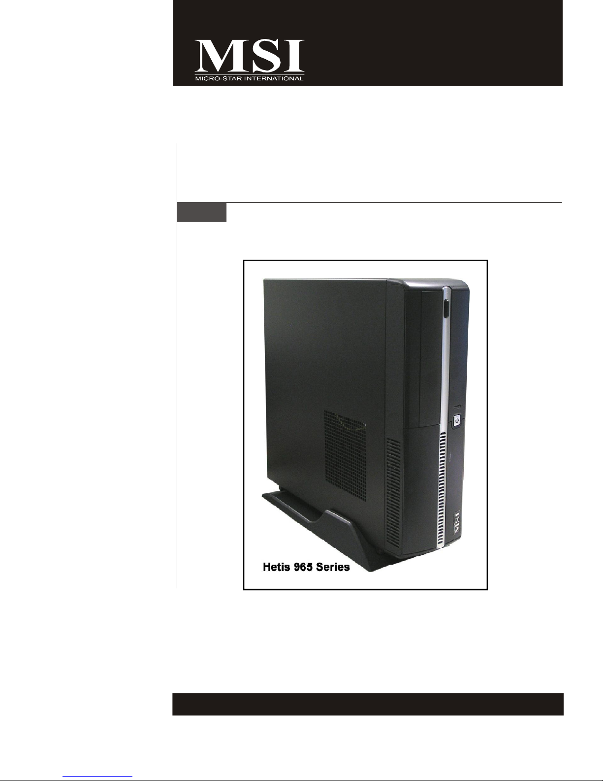
Hetis 965 Series
MS-6441 (V1.X) Barebone
G52-64411X2
FCC-B Radio Frequency Interference Statement
This equipment has been tested and
found to comply with the limits for a
class B digital device, pursuant to part
15 of the FCC rules. These limits are
designed to provide reasonable protection against harmful interference in a residential
installation. This equipment generates, uses and can radiate radio frequency energy
and, if not installed and used in accordance with the instruction manual, may cause
harmful interference to radio communications. However, there is no guarantee that
interference will not occur in a particular installation. If this equipment does cause
harmful interference to radio or television reception, which can be determined by
turning the equipment off and on, the user is encouraged to try to correct the
interference by one or more of the measures listed below.
=Reorient or relocate the receiving antenna.
=Increase the separation between the equipment and receiver.
=Connec the equipment into an outlet on a circuit different from that to which the
receiver is connected.
=Consult the dealer or an experienced radio/television technician for help.
Notice 1
The changes or modifications not expressly approved by the party responsible for
compliance could void the user’s authority to operate the equipment.
Notice 2
Shielded interface cables and A.C. power cord, if any, must be used in order to
comply with the emission limits.
VOIR LA NOTICE D’INSTALLATION AVANT DE RACCORDER AU RESEAU.
Micro-Star International
Hetis 965
This device complies with Part 15 of the FCC Rules. Operation is subject to the
following two conditions:
(1) this device may not cause harmful interference, and
(2) this device must accept any interference received, including interfer ence that
may cause undesired operation.
ii

Trademarks
All trademarks are the properties of their respective owners.
Intel® and Pentium® are registered trademarks of Intel Corporation.
PS/2 and OS®/2 are registered trademarks of International Business Machines
Corporation.
Windows® 95/98/2000/NT/XP are registered trademarks of Microsoft Corporation.
Netware® is a registered trademark of Novell, Inc.
Award® is a registered trademark of Phoenix Technologies Ltd.
AMI® is a registered trademark of American Megatrends Inc.
U.S. Patent Numbers.
4,631,603; 4,819,098; 4,907,093; 5,315,448; and 6,516,132.
This product incorporates copyright protection technology that is protected by U.S.
patents and other intellectual property rights. Use of this copyright protection technology must be authorized by Macrovision, and is intended for home and other limited
viewing uses only unless otherwise authorized by Macrovision. Reverse engineer-
ing or disassembly is prohibited.
Revision History
Revision Revision History Date
V1.1 First release May 2007
Copyright Notice
The material in this document is the intellectual property of MICRO-STAR
INTERNATIONAL. We take every care in the preparation of this document, but no
guarantee is given as to the correctness of its contents. Our products are under
continual improvement and we reserve the right to make changes without notice.
iii

Safety Instructions
1. Always read the safety instructions carefully.
2. Keep this User’ s Manual for future reference.
3. Keep this equipment away from humidity.
4. Lay this equipment on a reliable flat surface before setting it up.
5. The openings on the enclosure are for air convection hence protects the
equipment from overheating. DO NOT COVER THE OPENINGS.
6. Make sure the voltage of the power source and adjust properly 115/230V
before connecting the equipment to the power inlet.
7. Place the power cord such a way that people can not step on it. Do not
place anything over the power cord.
8. Always Unplug the Power Cord before inserting any add-on card or module.
9. All cautions and warnings on the equipment should be noted.
10. Never pour any liquid into the opening that could damage or cause electrical
shock.
11. If any of the following situations arises, get the equipment checked by a
service personnel:
- The power cord or plug is damaged.
- Liquid has penetrated into the equipment.
- The equipment has been exposed to moisture.
- The equipment has not work well or you can not get it work according to
User’s Manual.
- The equipment has dropped and damaged.
- The equipment has obvious sign of breakage.
12. DO NOT LEAVE THIS EQUIPMENT IN AN ENVIRONMENT UNCONDITIONED,
STORAGE TEMPERATURE ABOVE 400 C (1020F), IT MAY DAMAGE THE
EQUIPMENT.
CAUTION: Danger of explosion if battery is incorrectly replaced.
Replace only with the same or equivalent type recommended by the
manufacturer.
iv
Warning:
1. For every changes in powercord’s usage, please use an approved power
cord with condition greater or equal to H05VV-F,3G , 0.75mm2.
2. Internal part is hazardous moving parts, please keep fingers and other
body parts away.
3. For pluggable equipment, the socket-outlet shall be installed near the
equipment and shall be easily accessible.
4. Do not disable the protective earth pin from the plug, the equipment must
be connected to an earthed mains socket-outlet.
v
WEEE Statement
vi
vii
viii

CONTENTS
Chapter 1. Getting Started................................................................................1-1
Mainboard Specifications................................................................................1-2
System Configuration......................................................................................1-4
Thermal Solution..............................................................................................1-7
Chapter 2. Hardware Setup..............................................................................2-1
Mainboard Layout...........................................................................................2-2
CPU (Central Processing Unit)........................................................................2-3
Memory............................................................................................................2-4
Power Supply..................................................................................................2-5
Front Panel.......................................................................................................2-6
Back Panel.......................................................................................................2-7
Connectors......................................................................................................2-9
Jumper.............................................................................................................2-12
Slot..................................................................................................................2-13
Chapter 3. System Assembly...........................................................................3-1
Overview........................................................................................................3-2
Installation Procedures.....................................................................................3-4
Chapter 4. BIOS Setup.........................................................................................4-1
Entering Setup.................................................................................................4-2
The Menu Bar.................................................................................................4-4
Main.................................................................................................................4-5
Advanced........................................................................................................4-6
Boot.................................................................................................................4-13
Security...........................................................................................................4-16
Chipset............................................................................................................4-17
Exit...................................................................................................................4-20
Appendix A. Realtek ALC888 Audio................................................................A-1
Installing the Realtek HD Audio Driver.............................................................A-2
Software Configuration..................................................................................A-4
Hardware Setup...........................................................................................A-18
ix
Chapter 1
Getting Started
Congratulations for purchasing Hetis 965 Series (MS-6441)
Barebone. Hetis 965 Series is your best Slim PC choice.
With the fantastic appearance and small form factor, it
can easily be set anywhere. The feature packed platform
also gives you an exciting PC experience.
MS-6441 Barebone
Mainboard Specifications
Processor Support
- Supports Intel® Celeron D, Pentium 4, Pentium D, Core 2 Duo / Core
2 Extreme (Conroe) / Core 2 Quad (Kentsfield) processors in LGA775
Package.
Supported FSB
- 533 / 800 / 1066 MHz
Chipset
- North Bridge: Intel® G965 Chipset
- South Bridge: Intel® ICH8 Chipset
Memory Support
- DDR2 533 / 667 / 800 SDRAM (4GB Max)
- 2 DDR2 DIMMs (240pin / 1.8V)
LAN
- Supports Giga LAN by Intel® 82566DC
IEEE 1394
- Chip integrated by VIA® VT6307
- Transfer rate is up to 400Mbps
Audio
- Chip integrated by Realtek® ALC888
- Flexible 8-channel audio
- Compliant with Azalia 1.0 Spec
IDE
- 1 IDE port by JMicron JMB368
- Supports Ultra DMA 66 / 100 mode
- Supports PIO, Bus Master operation mode
SATA
- 2 SATA ports by Intel® ICH8
- Supports two SATA devices
- Supports storage and data transfers at up to 300 MB/s
1-2
Connectors
Back Panel
- 1 PS/2 Mouse Port
- 1 PS/2 Keyboard Port
- 2 Serial Ports
- 1 VGA Port
- 1 LAN Jack (RJ45)
- 1 IEEE 1394 Port
- 4 USB 2.0 Ports
- 6 Audio Jacks
Front Panel
- 2 Audio Jacks (Headphone and Microphone)
- 2 USB 2.0 Ports
- 1 IEEE 1394 Port
- 1 Chassis Intrusion Switch
Getting Started
On-Board Pinheaders
- 1 CD-In Pinheader
- 1 Card Reader Pinheader
- 1 SPDIF-Out Pinheader
(For HDMI Graphics Card Audio Line Use Only)
Slots
- 1 PCI-X Slot (For Riser Card Use Only)
Form Factor
- Proprietary (334MM x 190 MM)
Mounting
- 5 mounting holes
1-3
MS-6441 Barebone
System Configuration
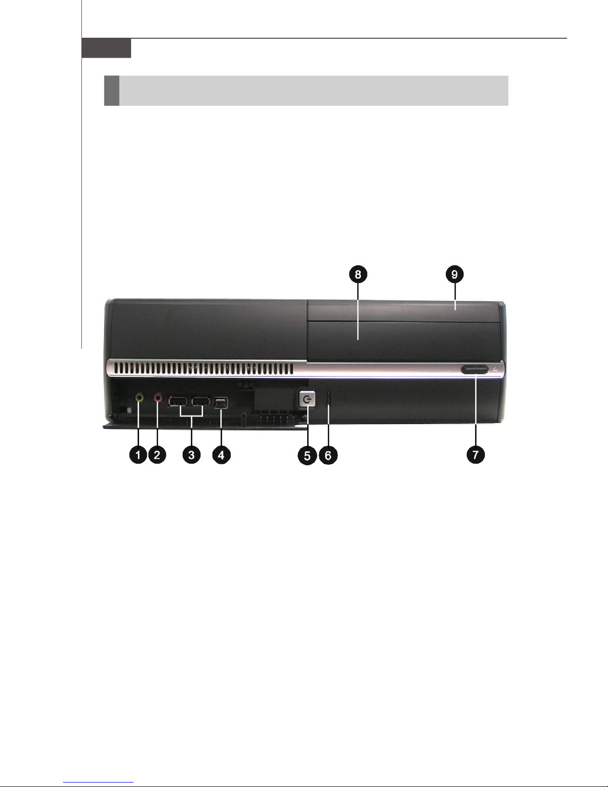
Front View
1. Headphone (Green) 6. HDD LED
2. Microphone (Pink) 7. ODD Eject / Close Button
3. USB 2.0 Ports 8. Optical Disk Drive (Optional)
4. IEEE 1394 Port 9. Card Reader Drive (Optional)
5. Power Button / Power LED
1-4

Back View
Getting Started
1. Voltage Selector 8. VGA Port
2. Power Jack 9. Audio Jacks
3. Ventilation Hole 10. Power Switch
4. USB 2.0 Ports 11. Support Bracket Spring
5. PS/2 Mouse (Green) 12. LAN Jack (RJ45)
6. PS/2 Keyboard (Purple) 13. IEEE 1394 Port
7. Serial Ports 14. Expansion Slots
1-5
MS-6441 Barebone
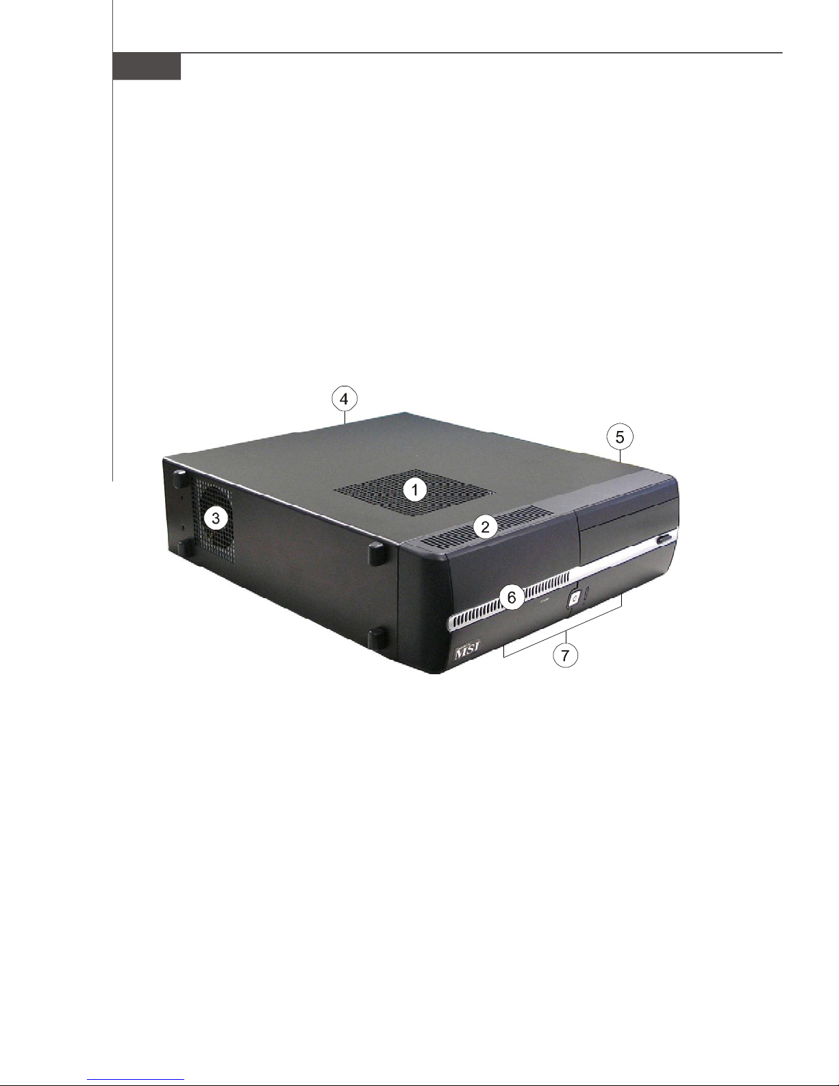
Chassis Design
† Dimension: 330MM (D) x 320MM (W) x 94MM (H)
† Minimized screw structure
† Detachable bay housing
† Multiple ventilation holes
Back
Side
Bottom
1. CPU Fan Ventilation Hole 5. System Ventilation Hole
2. System Ventilation Hole 6. System Ventilation Hole
3. System Fan Ventilation Hole 7. System Ventilation Hole
4. Power Supply Ventilation Hole
1-6
Getting Started
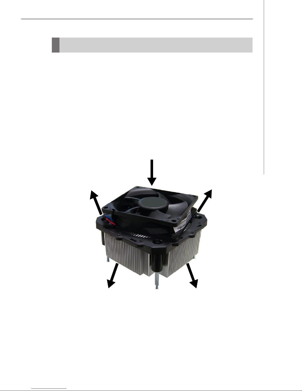
Thermal Solution
To prevent the system from overheating, we have adopted a specially designed CPU
cooler and multiple ventilation holes for better cooling effects. The specially designed
CPU cooler supports Intel® LGA775 - Prescott Pentium® D and Conroe CoreTM E6000
Sequence. The following figures illustrate how the system fan effectively exhausts
hot air through multiple ventilation holes.
CPU Cooler Air Flow Direction
Air In
Air Out Air Out
Air Out
Air Out
1-7
MS-6441 Barebone
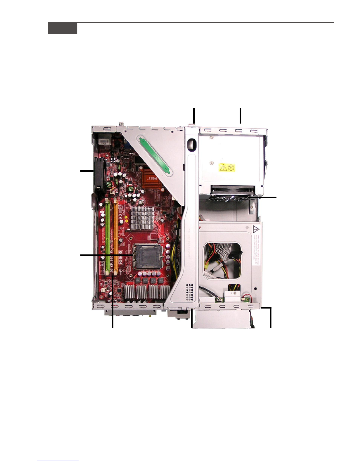
System Design
System
Fan
Back Panel Power Supply
Power
Supply Fan
CPU
Socket
Memory
DIMM Slots
Front Panel
Driver Bays
(from top to bottom)
Card Reader Drive
Optical Disk Drive
Hard Disk Drive
1-8
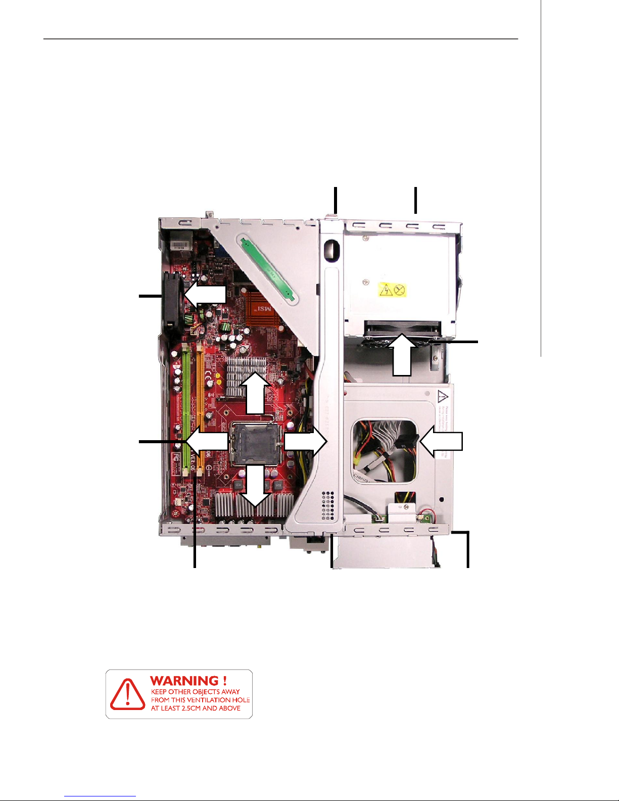
System Air Flow Direction
System
Fan
Getting Started
Back Panel Power Supply
Power
Supply Fan
CPU
Socket
Memory
DIMM Slots
Front Panel
After the installation is completed, please keep other
objects away from the ventilation hole at least 2.5cm
and above. Do not block the ventilation hole.
Driver Bays
(from top to bottom)
Card Reader Drive
Optical Disk Drive
Hard Disk Drive
1-9

Chapter 2
Hardware Setup
This chapter provides you with the information about hardware setup procedures. While doing the installation, be
careful in holding the components and follow the installation
procedures. For some components, if you install in the wrong
orientation, the components will not work properly.
Use a grounded wrist strap before handling computer
components. Static electricity may damage the components.
ONLY FOR SERVICE PERSONEL
Always unplug the power cord before
inserting any add-on card or module.
MS-6441 Barebone
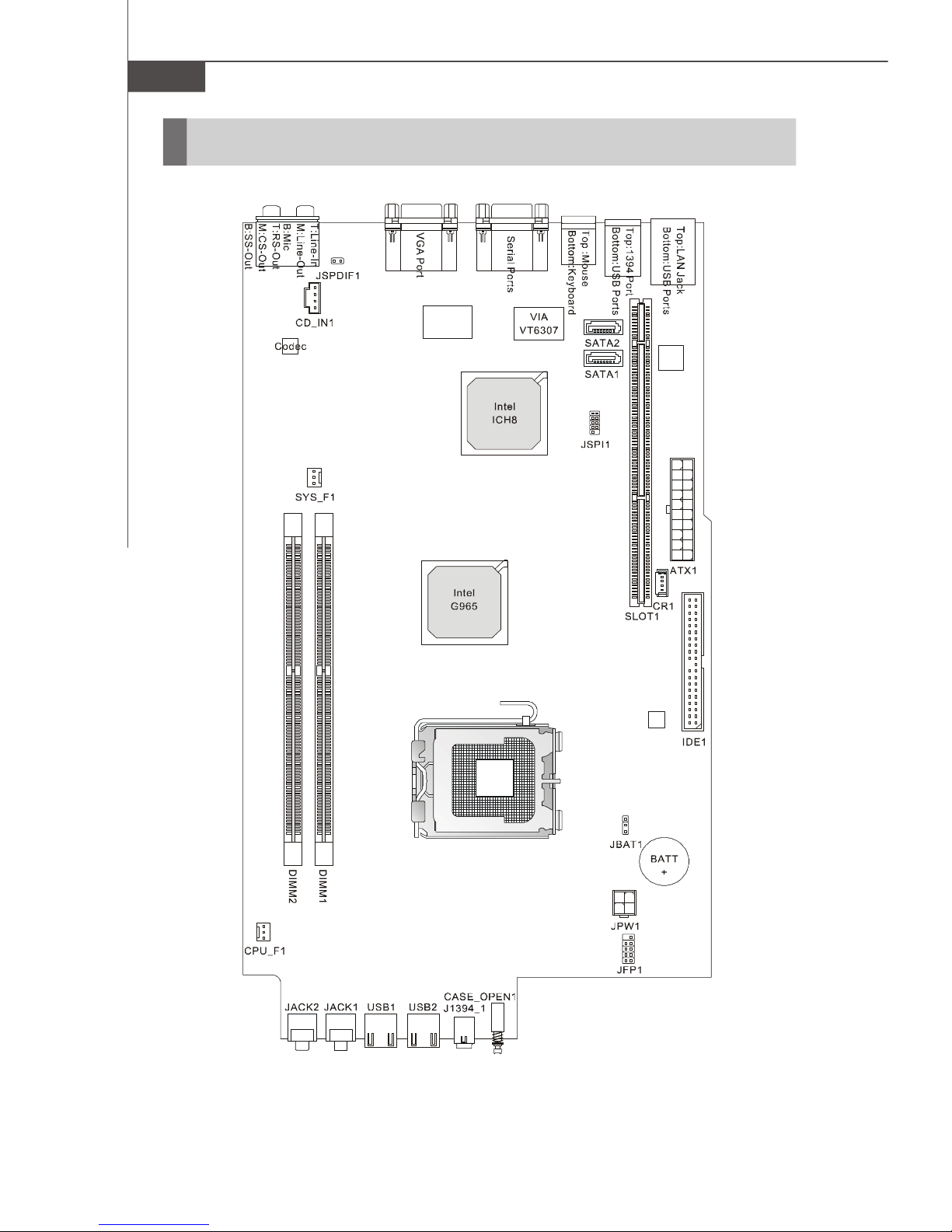
Mainboard Layout
2-2
MS-7334 (V1.X) Mainboard

Hardware Setup
CPU (Central Processing Unit)
The mainboard supports Intel® Prescott Pentium® D and Intel® Conroe CoreTM E6000
Sequence. The mainboard uses a CPU socket called LGA775. When you are installing the CPU, make sure to install the cooler to prevent overheating. If you do not have
the CPU cooler, contact your dealer to purchase and install them before turning on the
computer.
Important
Overheating
Overheating will seriously damage the CPU and system, always make
sure the cooling fan can work properly to protect the CPU from
overheating.
Replacing the CPU
While replacing the CPU, always turn off the power supply or unplug the
power supply’s power cord from grounded outlet first to ensure the
safety of CPU.
Overclocking
This motherboard is designed to support overclocking. However, please
make sure your components are able to tolerate such abnormal setting,
while doing overclocking. Any attempt to operate beyond product specifications is not recommended. We do not guarantee the damages or
risks caused by inadequate operation or beyond product specifications.
2-3
MS-6441 Barebone
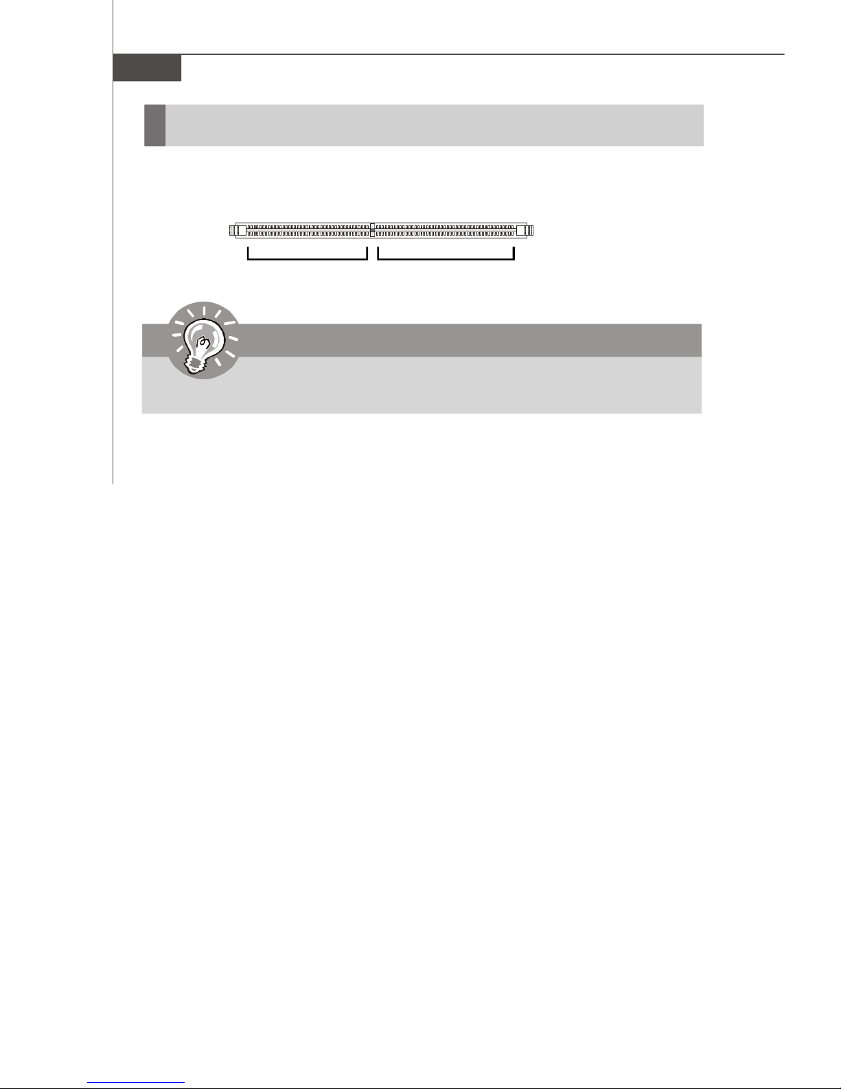
Memory
These DIMM slots are used for installing memory modules.
DIMM1~2
240-pin, 1.8V
56 x 2 = 112-pin
64 x 2 = 128-pin
Important
Each DIMM slot supports up to a maximum size of 2GB.
2-4
Hardware Setup
Power Supply
ATX 20-Pin Power Connector: ATX1
This connector allows you to connect to an power supply. To connect to the power
supply, make sure the plug of the power supply is inserted in the proper orientation
and the pins are aligned. Then push down the power supply firmly into the connector.
11
20
ATX1
1
10
PIN SIGNAL
1 3.3V
2 3.3V
3 GND
4 5V
5 GND
6 5V
7 GND
8 PW_OK
9 5V_SB
10 12V
ATX 12V Power Connector: JPW1
This 12V power connector is used to provide power to the CPU.
Pin Definition
Pin Definition
2
4
JPW1
1
3
PIN SIGNAL
1 GND
2 GND
3 12V
4 12V
PIN SIGNAL
11 3.3V
12 -12V
13 GND
14 PS_ON
15 GND
16 GND
17 GND
18 -5V
19 5V
20 5V
Important
1. Make sure that all the connectors are connected to proper ATX power
supplies to ensure stable operation of the mainboard.
2. Power supply of 250 watts (and above) is highly recommended for
system stability.
3. ATX 12V power connection should be greater than 18A.
4. For this model, you must use a power supply that comes with a -5V pin
supply.
2-5
MS-6441 Barebone
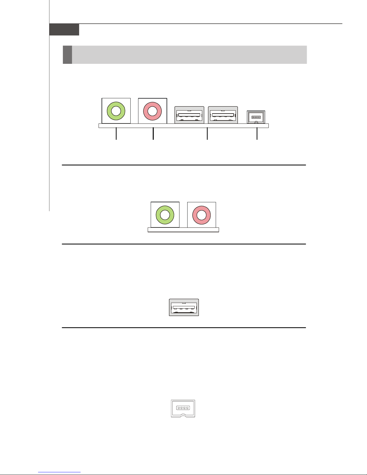
Front Panel
The Front Panel provides the following connectors:
Headphone
(Green)
(Pink)
USB PortsMicrophone
1394 Port
Audio Ports
These audio ports allow you to connect front audio devices.
USB Ports
The mainboard provides a UHCI (Universal Host Controller Interface) Universal Serial
Bus root for attaching USB devices such as keyboard, mouse or other USB-compatible devices. You can plug the USB devices directly into these connectors.
1394 Port
The front panel provides one IEEE 1394 port. This smaller one is designed for you to
connect the IEEE 1394 device with external power. The IEEE 1394 high-speed serial
bus complements USB by providing enhanced PC connectivity for a wide range of
devices, including consumer electronics audio/video (A/V) appliances, storage
peripherals, other PCs, and portable devices.
2-6
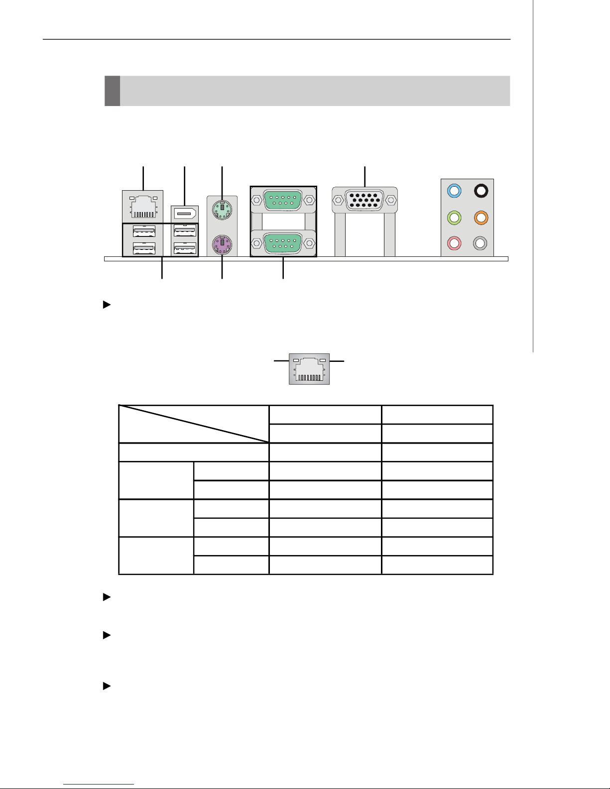
Back Panel
The Rear Panel provides the following connectors:
Hardware Setup
LAN
1394 Port
USB Ports Keyboard
Mouse VGA Port
Serial Ports
Line-In
Line-Out
Mic
RS-Out
CS-Out
SS-Out
LAN
The standard RJ-45 LAN jack is for connection to the Local Area Network (LAN). You
can connect a network cable to it.
Right LEDLeft LED
Left LED
Active LED
Right LED
10 / 100 / 1000M Speed LED
LED Color
10M Cable
Plug-in
100M Cable
Plug-in
1000M Cable
Plug-in
No Transmission
Transition
No Transmission
Transition
No Transmission
Transition
Yellow
OFF
Yellow, Blinking
OFF
Yellow, Blinking
OFF
Yellow, Blinking
Green / Orange
OFF
OFF
Green, Lighting
Green, Lighting
Orange, Lighting
Orange, Lighting
1394 Port
The IEEE1394 port on the back panel provides connection to IEEE1394 devices.
USB Ports
The USB (Universal Serial Bus) port is for attaching USB devices such as keyboard,
mouse, or other USB-compatible devices.
Mouse / Keyboard
The standard PS/2® mouse/keyboard DIN connector is for a PS/2® mouse/keyboard.
2-7

MS-6441 Barebone
Serial Ports
The serial port is a 16550A high speed communications port that sends/ receives 16
bytes FIFOs. You can attach a serial mouse or other serial devices directly to the
connector.
VGA Port
The DB15-pin female connector is provided for monitor.
Audio Ports
These audio connectors are used for audio devices. You can differentiate the color
of the audio jacks for different audio sound effects.
Line-In (Blue) - Line In, is used for external CD player, tapeplayer or other
audio devices.
Line-Out (Green) - Line Out, is a connector for speakers or headphones.
Mic (Pink) - Mic, is a connector for microphones.
RS-Out (Black) - Rear-Surround Out in 4/ 5.1/ 7.1 channel mode.
CS-Out (Orange) - Center/ Subwoofer Out in 5.1/ 7.1 channel mode.
SS-Out (Gray) - Side-Surround Out 7.1 channel mode.
2-8
 Loading...