


915PM/915GM/915GVM/910GLM
MS-7033 (v1.X) M-ATX Mainboard
G52-M7033X1
i
Manual Rev: 1.0
Release Date: June 2004
FCC-B Radio Frequency Interference Statement
This equipment has been tested and found to comply with the limits for a class B digital device, pursuant to part 15 of the FCC rules. These limits are designed to provide reasonable protection against harmful interference when the equipment is operated in a commercial environment. This equipment generates, uses and can radiate radio frequency energy and, if not installed and used in accordance with the instruction manual, may cause harmful interference to radio communications. Operation of this equipment in a residential area is likely to cause harmful interference, in which case the user will be required to correct the interference at his own expense.
Notice 1
The changes or modifications not expressly approved by the party responsible for compliance could void the user’s authority to operate the equipment.
Notice 2
Shielded interface cables and A.C. power cord, if any, must be used in order to comply with the emission limits.
VOIR LA NOTICE D’INSTALLATION AVANT DE RACCORDER AU RESEAU.
Micro-StarInternational
MS-7033
This device complies with Part 15 of the FCC Rules. Operation is subject to the following two conditions:
(1)this device may not cause harmful interference, and
(2)this device must accept any interference received, including interference that may cause undesired operation
ii

Copyright Notice
The material in this document is the intellectual property of MICRO-STAR INTERNATIONAL. We take every care in the preparation of this document, but no guarantee is given as to the correctness of its contents. Our products are under continual improvement and we reserve the right to make changes without notice.
Trademarks
All trademarks are the properties of their respective owners.
AMD, Athlon™, Athlon™ XP, Thoroughbred™, and Duron™ are registered trademarks of AMD Corporation.
Intel® and Pentium® are registered trademarks of Intel Corporation.
PS/2 and OS®/2 are registered trademarks of International Business Machines Corporation.
Microsoft is a registered trademark of Microsoft Corporation. Windows® 98/2000/NT/
XP are registered trademarks of Microsoft Corporation.
NVIDIA, the NVIDIA logo, DualNet, and nForce are registered trademarks or trademarks of NVIDIA Corporation in the United States and/or other countries.
Netware® is a registered trademark of Novell, Inc.
Award® is a registered trademark of Phoenix Technologies Ltd.
AMI® is a registered trademark of American Megatrends Inc.
Kensington and MicroSaver are registered trademarks of the Kensington Technology Group.
PCMCIA and CardBus are registered trademarks of the Personal Computer Memory
Card International Association.
Revision History
Revision |
Revision History |
Date |
V1.0 |
First release for PCB 1.X |
June 2004 |
|
with Intel 915P/915G/915GV/ |
|
|
910GL & ICH6 |
|
iii

Technical Support
If a problem arises with your system and no solution can be obtained from the user’s manual, please contact your place of purchase or local distributor. Alternatively, please try the following help resources for further guidance.
hVisit the MSI homepage & FAQ site for technical guide, BIOS updates, driver updates, and other information: http://www.msi.com.tw & http://www.msi. com.tw/program/service/faq/faq/esc_faq_list.php
hContact our technical staff at: support@msi.com.tw
Safety Instructions
1.Always read the safety instructions carefully.
2.Keep this User’s Manual for future reference.
3.Keep this equipment away from humidity.
4.Lay this equipment on a reliable flat surface before setting it up.
5.The openings on the enclosure are for air convection hence protects the equipment from overheating. Do not cover the openings.
6.Make sure the voltage of the power source and adjust properly 110/220V before connecting the equipment to the power inlet.
7.Place the power cord such a way that people can not step on it. Do not place anything over the power cord.
8.Always Unplug the Power Cord before inserting any add-on card or module.
9.All cautions and warnings on the equipment should be noted.
10.Never pour any liquid into the opening that could damage or cause electrical shock.
11.If any of the following situations arises, get the equipment checked by a service
personnel:
h The power cord or plug is damaged.
h Liquid has penetrated into the equipment.
h The equipment has been exposed to moisture.
hThe equipment has not work well or you can not get it work according to
User’s Manual.
hThe equipment has dropped and damaged.
hThe equipment has obvious sign of breakage.
12.Do not leave this equipment in an environment unconditioned, storage
temperature above 600 C (1400F), it may damage the equipment.
CAUTION: Danger of explosion if battery is incorrectly replaced. Replace only with the same or equivalent type recommended by the manufacturer.
iv
CONTENTS
FCC-B Radio Frequency Interference Statement ........................................................ |
ii |
Copyright Notice ........................................................................................................... |
iii |
Revision History ............................................................................................................ |
iii |
Technical Support ........................................................................................................ |
iv |
Safety Instructions ...................................................................................................... |
iv |
Chapter 1. Getting Started ................................................................................... |
1-1 |
Mainboard Specifications .................................................................................. |
1-2 |
Mainboard Layout .............................................................................................. |
1-4 |
Packing Contents ............................................................................................... |
1-5 |
Chapter 2. Hardware Setup ................................................................................. |
2-1 |
Quick Components Guide .................................................................................. |
2-2 |
Central Processing Unit: CPU ............................................................................ |
2-3 |
Introduction of LGA 775 CPU ..................................................................... |
2-3 |
CPU, Heatsink & Fan Installation ................................................................ |
2-4 |
Memory ............................................................................................................... |
2-7 |
Introduction to DDR SDRAM ....................................................................... |
2-7 |
DIMM Module Combination .......................................................................... |
2-8 |
Installing DDR Modules ............................................................................... |
2-8 |
Power Supply ..................................................................................................... |
2-9 |
ATX 24-Pin Power Connector: ATX1 ......................................................... |
2-9 |
ATX 12V Power Connector: JPW1 ............................................................ |
2-9 |
Back Panel ........................................................................................................ |
2-10 |
Mouse/Keyboard Connector .................................................................... |
2-10 |
VGA Connector (optional) ....................................................................... |
2-10 |
Serial Port Connector ............................................................................... |
2-11 |
USB Connectors ....................................................................................... |
2-11 |
IEEE1394 Port (optional) ........................................................................... |
2-11 |
LAN (RJ-45) Jack (optional) .................................................................... |
2-12 |
Audio Port Connectors ............................................................................. |
2-12 |
Parallel Port Connector: LPT1 .................................................................. |
2-13 |
Connectors ....................................................................................................... |
2-14 |
Floppy Disk Drive Connector: FDD1 ........................................................ |
2-14 |
Fan Power Connectors: CPU_FAN1 CPU_FAN2/SYS_FAN1 ................. |
2-14 |
Hard Disk Connectors: IDE1 & IDE2 (optional) ........................................ |
2-15 |
Serial ATA HDD Connectors: SATA1 & SATA2 ........................................ |
2-16 |
Front Panel Connectors: JFP1 & JFP2 ..................................................... |
2-17 |
v
CD-In Connector: JCD1 ............................................................................ |
2-18 |
Front Panel Audio Connector: JAUD1 ..................................................... |
2-18 |
Serial Port Connector: JCOM2 ................................................................. |
2-19 |
Front USB Connectors: JUSB1 & JUSB2 ................................................ |
2-19 |
SPDIF Connector: JSPD1 .......................................................................... |
2-20 |
IEEE 1394 Connectors: JFW1 (optional) ................................................. |
2-21 |
Jumpers ............................................................................................................ |
2-21 |
Clear CMOS Jumper: JBAT1 .................................................................... |
2-21 |
Slots .................................................................................................................. |
2-22 |
PCI Express Slots ..................................................................................... |
2-22 |
PCI (Peripheral Component Interconnect) Slots ...................................... |
2-23 |
PCI Interrupt Request Routing .................................................................. |
2-23 |
Chapter 3. BIOS Setup ........................................................................................... |
3-1 |
Entering Setup .................................................................................................... |
3-2 |
Control Keys ............................................................................................... |
3-2 |
Getting Help ................................................................................................ |
3-3 |
The Main Menu ................................................................................................... |
3-4 |
Standard CMOS Features .................................................................................. |
3-6 |
Advanced BIOS Features .................................................................................. |
3-8 |
Advanced Chipset Features ........................................................................... |
3-11 |
Integrated Peripherals ...................................................................................... |
3-14 |
Power Management Setup .............................................................................. |
3-19 |
PNP/PCI Configurations .................................................................................... |
3-21 |
H/W Monitor ...................................................................................................... |
3-22 |
Frequency/Voltage Control .............................................................................. |
3-24 |
Load Fail-Safe/Optimized Defaults ................................................................. |
3-26 |
Set Supervisor/User Password ...................................................................... |
3-27 |
Chapter 4. Introduction to VIA VT6410 IDE RAID ............................................. |
4-1 |
Introduction ......................................................................................................... |
4-2 |
RAID Basics ................................................................................................ |
4-2 |
RAID 0 (Striping) ......................................................................................... |
4-2 |
RAID 1 (Mirroring) ....................................................................................... |
4-3 |
JBOD (Spanning) ........................................................................................ |
4-3 |
BIOS Configuration ............................................................................................. |
4-4 |
Create Disk Array ....................................................................................... |
4-5 |
Delete Disk Array ........................................................................................ |
4-8 |
Create and Delete Spare Hard Drive ......................................................... |
4-9 |
Select Boot Array ..................................................................................... |
4-10 |
vi
View Serial Number of Hard Drive .......................................................... |
4-10 |
Duplicate Critical RAID 1 Array ................................................................ |
4-11 |
Rebuild Broken RAID 0/0+1 Array ........................................................... |
4-12 |
Installing Software ........................................................................................... |
4-14 |
Install Driver in Windows XP/2000 .......................................................... |
4-14 |
Installation of VIA IDE RAID Utility ............................................................ |
4-15 |
Using VIA RAID Tool ......................................................................................... |
4-18 |
Chapter 5. Introduction to CMI 9880L Audio Codec ...................................... |
5-1 |
Installing the Audio Codec Driver ...................................................................... |
5-2 |
Software Configuration ..................................................................................... |
5-3 |
Main Setting ................................................................................................ |
5-3 |
Mixer ........................................................................................................... |
5-8 |
Device Setting .......................................................................................... |
5-11 |
Effect ........................................................................................................ |
5-12 |
Information ................................................................................................ |
5-12 |
vii

|
Getting Started |
Chapter |
1. Getting |
Getting Started
Thank you for choosing the 915PM/915GM/915GVM/ 910GLM (MS-7033) v1.X M-ATX mainboard. The 915PM/915GM/ 915GVM/910GLM mainboard is based on Intel® 915P/G/GV/GL and
Intel® ICH6 chipset for optimal system efficiency. Designed to fit the advanced Intel® Pentium 4 Prescott (LGA775)processor, the
915PM/915GM/915GVM/910GLM mainboard delivers a high performance and professional desktop platform solution.
1-1

MS-7033 M-ATX Mainboard
Mainboard Specifications
CPU
hSupports Intel® Pentium 4 Prescott (LGA775) processors in LGA775 package
hSupports 533MHz, 800MHz FSB
hSupports 2004 Performance FMB CPU VR Design
hSupports 3 or 4 pin CPU Fan Pin-Header with Fan Speed Control
(For the latest information about CPU, please visit http://www.msi.com.tw/program/ products/mainboard/mbd/pro_mbd_cpu_support.php)
Chipset
hIntel® 915P/915G/915GV/910GL Chipset
-Supports 533/800MHz Intel NetBurst micro-architecture bus (910GL supports 533 MHz only)
-Supports PCI Express x16 interface (not available for 915GV/910GL)
-Supports DDR 333/400 memory interface
-Integrated Intel GMA 900 graphic controller with ADD2 interface support (not available for 915P)
hIntel® ICH6 chipset (609 mBGA)
-High Definition Audio interface
-Supports PCI Express x1 interface
-2 Serial ATA Host Controllers
-1 channel Ultra ATA 100 bus Master IDE controller
-8 USB 2.0/1.1 ports
-Supports SMBus 2.0
Main Memory
hSupports two 64-bit wide DDR data channels
hAvailable bandwidth up to 3.2GB/s (DDR 400) for single-channel mode and
6.4 GB/s (DDR 400) for dual-channel mode
hSupports 128MB, 256MB or 512MB DDR technologies
hSupports only x8, x16 DDR devices with 2-bank
(For the updated supporting memory modules, please visit http://www.msi.com.tw/ program/products/mainboard/mbd/pro_mbd_trp_list.php.)
Slots
hOne PCI Express x16 slot (supports PCI Express Bus specification v1.0a compliant)
(not available for 915GV/910GL)
hOne PCI Express x1 slot (supports PCI Express Bus specification v1.0a compliant)
hTwo 32-bit v2.2 Master PCI bus slots (support 3.3v/5v PCI bus interface)
On-Board IDE
hOne IDE controller on the ICH6 chipset provides IDE HDD/CD-ROM with PIO, Bus
Master and Ultra DMA66/100 operation modes
hAn IDE controller on the VIA VT6410 chipset with a channel (supports 2 IDE devices) provides IDE HDD/CD-ROM with PIO, Bus Master and Ultra DMA66/100/ 133 operation modes. (With Raid 0,1 support) (optional)
1-2

Getting Started
h Support 2 Serial ATA ports
On-Board Peripherals
hOn-Board Peripherals include:
-1 floppy port supports 1 FDD with 360K, 720K, 1.2M, 1.44M and 2.88Mbytes
-2 serial ports, Com1 on Rear IO, Com2 via pin header(IO bracket is optional)
-1 parallel port supports SPP/EPP/ECP mode
-1 Line-In / Line-Out / MIC-In / Surround Speaker Out / Center-Subwoofer Speaker
Out / Surround Back Speaker Out
-8 USB ports (Rear * 4/ Front * 4)
-1 RJ-45 LAN jack (optional)
-2 * 1394 ports (optional)
On-board LAN (optional)
hRealtek 8100C / 8110S / 8110SB (optional)
-Integrated Fast Ethernet MAC and PHY in one chip
-Supports 10Mb/s, 100Mb/s and 1000Mb/s (1000Mb/s for 8100S/SB only)
-Compliance with PCI 2.2
-Supports ACPI Power Management
Audio
h8 channels (HDA) audio codec
-Meet PC2001 audio performance requirement
-Can support SPDIF Out via bracket only (optional)
1394 (optional)
hSupports up to 2 * 1394 ports, one 6-pin 1394 connector on rear I/O, the other is supported by onboard pinheader. Transfer rate is up to 400Mbps
hControlled by VIA 6307 chipset
BIOS
h4Mb FWH
hProvides DMI2.0, WfM2.0, WOL, WOR, and SMBus for system management
Mounting and Dimension
hM-ATX Form Factor: 24.5 cm (W) x 24.5 cm (L)
h6 mounting holes
1-3
MS-7033 M-ATX Mainboard
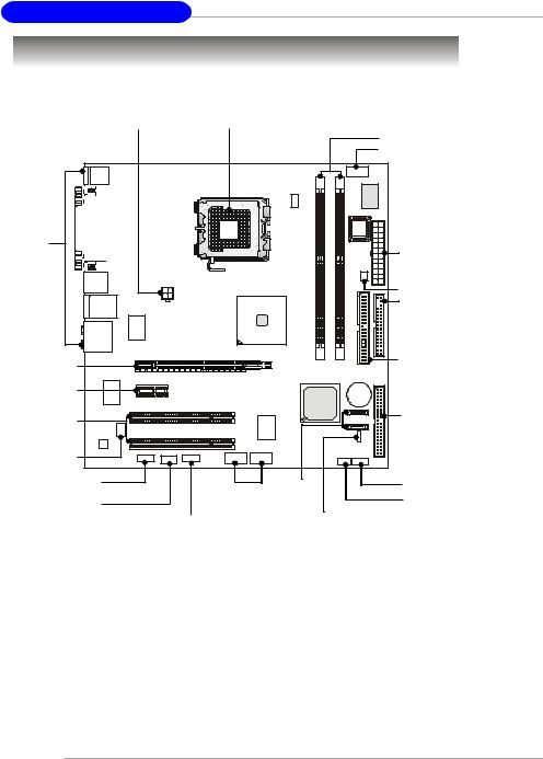
Mainboard Layout
Top : mouse
Bottom: keyboard
Top : Parallel Port |
|
Bottom: |
|
COM port |
|
VGA port (optional) |
|
T:IEEE 1394 (optional) |
|
B:USB port |
JPW1 |
T: LAN jack (optional) |
|
B: USB ports |
|
T:Line-In |
RTL8100C/ |
M:Line-Out |
8100S/8100SB |
B:Mic |
- (optional) |
T:Surround |
|
M:Center/Subwoofer |
|
B:Surround Back |
|
|
JCOM2 |
|
|
Winbond |
W83627THF |
CPU_FAN1 |
|
|
CPU_FAN2 |
|
ATX1 |
|
BIOS |
|
|
|
|
|
SYS_F1 |
|
DIMM1 |
DIMM2 |
|
Intel |
|
|
915P/915G/ |
|
|
915GV/910GL |
|
|
|
IDE1 |
FDD1 |
PCI-Ex16 |
VIA |
|
|
|
VT6307 |
|
|
|
(optional) |
PCI -Ex1 |
|
ICH6 |
|
|
||
|
|
|
|
|
PCI 2 |
|
VIA |
JSPD1 |
|
VT6410 |
|
PCI 3 |
|
(optional) |
|
|
|
|
|
HDA 8ch |
JAUD1 |
JCD1 JFW1(optional) |
|
Codec |
|
JUSB2 |
JUSB1 |
|
|
IDE 2
(optional)
BATT +
SATA2
SATA1
JBAT1
JFP2 JFP1
915PM/915GM/GVM/910GLM (MS-7033) v1.X M-ATX Mainboard
1-4
Getting Started
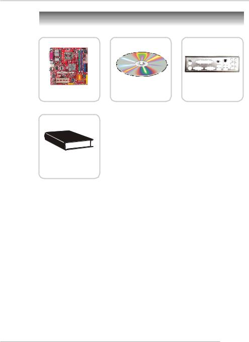
Packing Contents
MSI motherboard |
MSI Driver/Utility CD |
Back IO Shield |
User’s Guide
1-5

Hardware Setup |
Chapter 2. Hardware Setup |
Hardware Setup
This chapter tells you how to install the CPU, memory modules, and expansion cards, as well as how to setup the jumpers on the mainboard. Also, it provides the instructions on connecting the peripheral devices, such as the mouse, keyboard, etc.
While doing the installation, be careful in holding the components and follow the installation procedures.
2-1
MS-7033 M-ATX Mainboard
Quick Components Guide
JPW1, p.2-9 |
CPU, p.2-3 |
CPUF_FAN1 |
|
||
|
|
CPUF_FAN2, |
DDR DIMMs, p.2-7 |
||
|
|
|
p.2-14 |
||
|
|
|
JCOM2, p.2-19 |
||
|
|
|
|
||
Back Panel |
|
|
|
|
|
I/O, p.2-10 |
|
|
|
ATX1, p.2-9 |
|
|
|
|
|
SYSFAN1, p.2-14 |
|
|
|
|
|
FDD1, p.2-14 |
|
PCI Express x16, |
|
|
|
IDE1, p.2-15 |
|
|
|
|
|
||
p.2-22 |
|
|
|
|
|
PCI Express x1, |
|
|
|
|
|
p.2-22 |
|
|
|
|
|
PCI Slots 2/3, |
|
|
|
IDE2, p.2-15 |
|
|
|
|
(optional) |
||
p.2-22 |
|
|
|
||
|
|
|
|
||
JSPD1, p.2-20 |
|
|
|
|
|
JAUD1, p.2-18 |
JUSB1 |
|
SATA1 |
JFP1, p.2-17 |
|
|
|
SATA2, |
JFP2, p.2-17 |
||
JCD1, p.2-18 |
JUSB2, |
||||
p.2-16 |
|||||
|
|||||
JFW1, p.2-19 JBAT1,
p.2-20 |
p.2-21 |
|
|
(Optional) |
|
2-2
Hardware Setup
Central Processing Unit: CPU
The mainboard supports Intel® Pentium 4 / Celeron DTM (LGA775) processor. The mainboard uses a CPU socket called LGA775. When you are installing the CPU, make sure to install the heat sink/cooler to prevent overheating. If you do not have the CPU, contact your dealer to purchase and install them before turning on the computer.
For the latest information about CPU, please visit http://www.msi.com.tw/ program/products/mainboard/mbd/pro_mbd_cpu_support.php.
MSI Reminds You...
Overheating
Overheating will seriously damage the CPU and system, always make sure the cooling fan can work properly to protect the CPU from overheating.
Replacing the CPU
While replacing the CPU, always turn off the ATX power supply or unplug the power supply’s power cord from grounded outlet first to ensure the safety of CPU.
Overclocking
This motherboard is designed to support overclocking. However, please make sure your components are able to tolerate such abnormal setting, while doing overclocking. Any attempt to operate beyond product specifications is not recommended. We do not guarantee the damages or risks caused by inadequate operation or beyond product specifications.
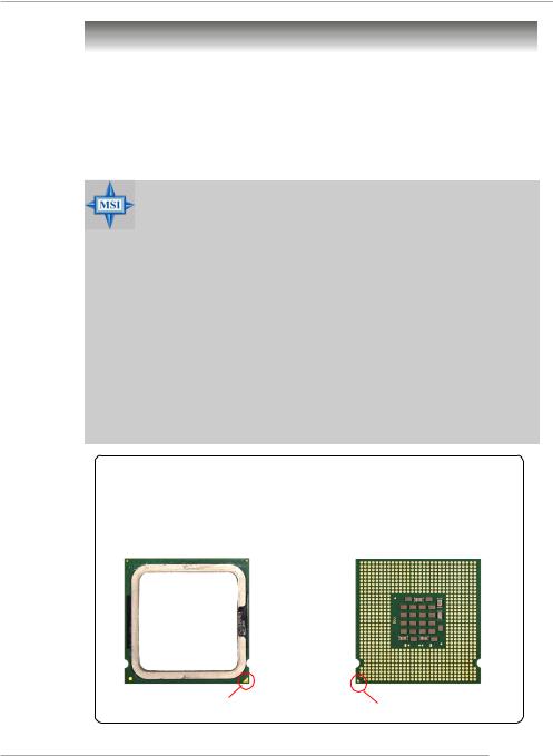
Introduction of LGA 775 CPU
The surface of LGA 775 CPU.
Remember to apply some silicone heat transfer compound on it for better heat dispersion.
The pin-pad side of LGA 775
CPU.
Yellow triangle is the Pin 1 indicator |
Yellow triangle is the Pin 1 indicator |
2-3

MS-7033 M-ATX Mainboard
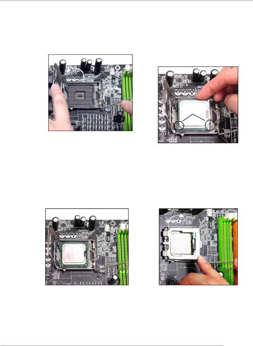
CPU, Heatsink & Fan Installation
When you are installing the CPU, make sure the CPU has a heat sink/ cooler fan attached on the top to prevent overheating. If you do not have the heat sink/cooler fan, contact your dealer to purchase and install them before turning on the computer. Meanwhile, do not forget to apply some silicon heat transfer compound on CPU before installing the heat sink/cooler fan for better heatsinking.
Follow the steps below to install the CPU & cooling fan correctly. Wrong installation will cause the damage of your CPU & mainboard.
1.The CPU has a plastic cap on it to protect the contact from damage.
Always cover it to protect the socket pin until you are going to install the CPU.
2.Remove the cap from lever hinge side (as the arrow shows).
3. The pins of socket reveal. |
4. Open the load lever. |
2-4
Hardware Setup
5.Lift the load lever up and open the load plate.
6.After confirming the CPU direction for correction mating, put down the CPU in the socket housing frame. Be sure to grape on the edge of the substrate. Note that the alignment keys are matched.
alignment key
7.Visually inspect if the CPU is seated well into the socket. If not, take out the CPU with purely vertical motion and reload it again.
8.Rotate the load plate onto the package.
2-5

MS-7033 M-ATX Mainboard
9.Engage the load while pressing down lightly onto the load plate, and then secure the lever with the hook under retention tab.
11.Press the four hooks down to fasten the fan. Then rotate the locking switch (refer to the correct direction marked on it) to lock the hooks again.
10.Align the holes on the mainboard with the heatsink first. Pull down the fan/heatsink until its four clips get wedged in the holes of the mainboard.
12.Turn over the mainboard to confirm that the clip-ends are corrected inserted.
locking switch
MSI Reminds You...
1.Confirm if your CPU heatsink/cooler is firmly installed before turning on your system.
2.Check the information in PC Health Status of H/W Monitor in BIOS (refer to p.3-20 for details) for the CPU temperature.
3.Make sure that the CPU socket pins are not turned up or pressed down.
2-6
Hardware Setup
Memory
The mainboard provides 2 slots for 184-pin DDR SDRAM DIMM (Double In-Line Memory
Module) modules and supports the memory size up to 2GB. You can install DDR266/
333/400 modules on the DDR DIMM slots (DDR 1~2).
For the updated supporting memory modules, please visit http://www.msi.com.tw/ program/products/mainboard/mbd/pro_mbd_trp_list.php.
DDR DIMM Slots
(DDR 1~2)
Introduction to DDR SDRAM
DDR (Double Data Rate) SDRAM is similar to conventional SDRAM, but doubles the rate by transferring data twice per cycle. It uses 2.5 volts as opposed to 3.3 volts used in SDR SDRAM, and requires 184-pin DIMM modules rather than 168-pin DIMM modules used by SDR SDRAM.
2-7

MS-7033 M-ATX Mainboard
DIMM Module Combination
Install at least one DIMM module on the slots. You can install either singleor doublesided modules in any order to meet your own needs.
Memory modules can be installed in any combination as follows:
Slot |
Memory Module |
TotalMemory |
DDR 1 |
|
|
(Bank 0 & 1) |
S/D |
64MB~1GB |
DDR 2 |
|
|
(Bank 2 & 3) |
S/D |
64MB~1GB |
|
|
|
Maximum System Memory Supported |
64MB~2GB |
|
|
|
|
S: Single Side |
D: Double Side |
|
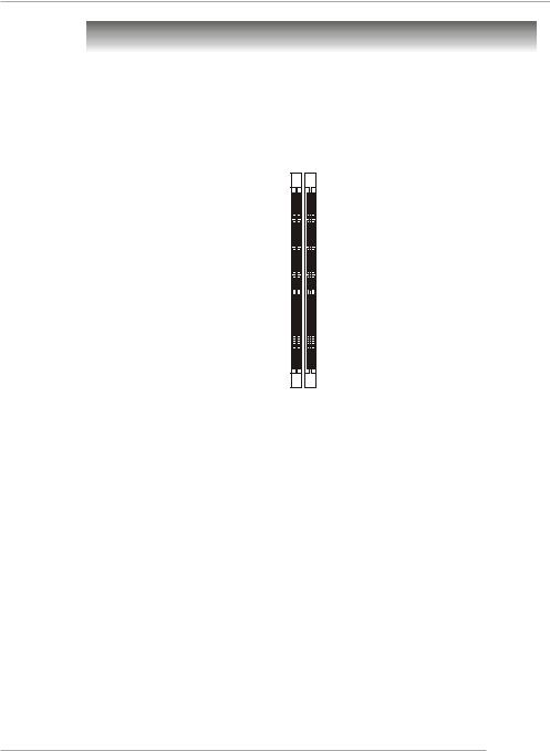
Installing DDR Modules
1.The DDR DIMM has only one notch on the center of module. The module will only fit in the right orientation.
2.Insert the DIMM memory module vertically into the DIMM slot. Then push it in until the golden finger on the memory module is deeply inserted in the socket.
3.The plastic clip at each side of the DIMM slot will automatically close.
Volt Notch
MSI Reminds You...
You can barely see the golden finger if the module is properly inserted in the socket.
2-8
Hardware Setup
Power Supply
The mainboard supports ATX power supply for the power system. Before inserting the power supply connector, always make sure that all components are installed properly to ensure that no damage will be caused.
ATX 24-Pin Power Connector: ATX1
This connector allows you to connect an SSI power supply. To connect the
SSI power supply, make sure the plug of the power supply is inserted in the proper orientation and the pins are aligned. Then push down the power supply firmly into the connector.
You may use the 20-pin ATX power supply or 24-pin SSI power supply as you like. If you’d like to use the ATX power supply, please plug your power supply along with pin 1 & pin 13 (refer to the image at the right hand). There is also a foolproof design on pin 11, 12, 23 & 24 to avoid wrong installation.
13 |
1 |
ATX1 |
|
24 |
12 |
Pin Definition
PIN |
SIGNAL |
PIN |
SIGNAL |
|
|
|
|
1 |
+3.3V |
13 |
+3.3V |
2 |
+3.3V |
14 |
-12V |
3 |
GND |
15 |
GND |
4 |
+5V |
16 |
PS-ON# |
5 |
GND |
17 |
GND |
6 |
+5V |
18 |
GND |
7 |
GND |
19 |
GND |
8 |
PWR OK |
20 |
Res |
9 |
5VSB |
21 |
+5V |
10 |
+12V |
22 |
+5V |
11 |
+12V |
23 |
+5V |
12 |
NC |
24 |
GND |
|
|
|
|
ATX 12V Power Connector: JPW1
This 12V power connector is used to provide power to the CPU.
JPW1 Pin Definition
JPW1 |
2 |
1 |
|
4 |
3 |
||
|
PIN |
SIGNAL |
1 |
GND |
2 |
GND |
3 |
12V |
4 |
12V |
MSI Reminds You...
1.These two connectors connect to the ATX power supply and have to work together to ensure stable operation of the mainboard.
2.Power supply of 350 watts (and above) is highly recommended for system stability.
3.For ATX 12V power connection, it should be greater than 18A.
2-9
MS-7033 M-ATX Mainboard
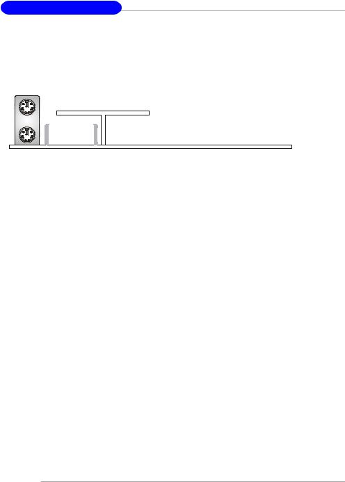
Back Panel
The back panel provides the following connectors: |
|
|
|
||
Parallel |
|
IEEE1394 |
LAN |
L-In |
Surround |
|
(Optional) |
|
|||
Mouse |
|
(Optional) |
|
||
|
|
|
|
|
Center/ |
|
|
|
|
|
Subwoofer |
Keyboard COM port |
VGA port |
USB Ports |
L-Out Surround |
||
|
(Optional) |
|
|
Mic |
Back |
Mouse/Keyboard Connector
The mainboard provides a standard PS/2® mouse/keyboard mini DIN connector for attaching a PS/2® mouse/keyboard. You can plug a PS/2® mouse/keyboard directly into this connector. The connector location and pin assignments are as follows:
|
|
|
Pin Definition |
||
6 |
5 |
PIN |
SIGNAL |
DESCRIPTION |
|
4 |
3 |
1 |
Mouse/Keyboard Data |
Mouse/Keyboard data |
|
|
|
2 |
NC |
No connection |
|
2 |
1 |
3 |
GND |
Ground |
|
4 |
VCC |
+5V |
|||
|
|
||||
PS/2 Mouse / Keyboard |
5 |
Mouse/KeyboardClock |
Mouse/Keyboardclock |
||
(6-pin Female) |
6 |
NC |
No connection |
||
VGA Connector (optional)
The mainboard provides a DB 15-pin female connector to connect a VGA monitor.
5 |
1 |
Pin |
Signal Description |
Pin |
Signal Description |
|
1 |
RED |
2 |
GREEN |
|||
|
|
|||||
|
|
3 |
BLUE |
4 |
N/C |
|
|
|
5 |
GND |
6 |
GND |
|
|
|
7 |
GND |
8 |
GND |
|
15 |
11 |
9 |
+5V |
10 |
GND |
|
VGA Connector |
11 |
N/C |
12 |
SDA |
||
13 |
Horizontal Sync |
14 |
Vertical Sync |
|||
(DB 15-pin) |
15 |
SCL |
|
|
||
2-10

Hardware Setup
Serial Port Connector
The mainboard offers one 9-pin male DIN connector as the serial port. The port is a 16550A high speed communication port that sends/receives 16 bytes FIFOs. You can attach a serial mouse or other serial devices directly to the connector.
|
|
|
|
|
|
|
Pin Definition |
|
|
1 |
2 |
3 |
4 5 |
|
|
|
|
|
|
|
PIN |
SIGNAL |
DESCRIPTION |
|
|||||
|
|
|
|
|
|
1 |
DCD |
Data Carry Detect |
|
|
|
|
|
|
|
2 |
SIN |
Serial In or Receive Data |
|
|
|
|
|
|
|
|
|||
|
|
|
|
|
|
3 |
SOUT |
Serial Out or Transmit Data |
|
|
6 |
7 |
8 |
9 |
|
4 |
DTR |
Data Terminal Ready) |
|
|
5 |
GND |
Ground |
|
|||||
9-Pin Male DIN Connector |
|
||||||||
6 |
DSR |
Data Set Ready |
|
||||||
|
|
|
|
|
|
7 |
RTS |
Request To Send |
|
|
|
|
|
|
|
8 |
CTS |
Clear To Send |
|
|
|
|
|
|
|
9 |
RI |
Ring Indicate |
|
|
|
|
|
|
|
|
|
|
|
|
|
|
|
|
|
|
|
|
|
USB Connectors
The mainboard provides an EHCI Universal Serial Bus root for attaching USB devices such as keyboard, mouse or other USB-compatible devices. You can plug the USB device directly into the connector.
|
|
|
|
|
USB Port Description |
||
|
|
|
|
PIN |
SIGNAL |
DESCRIPTION |
|
|
|
|
|
1 |
VCC |
+5V |
|
1 |
2 |
3 |
4 |
2 |
-Data 0 |
Negative Data Channel 0 |
|
3 |
+Data0 |
Positive Data Channel 0 |
|||||
|
|
|
|
||||
|
|
|
|
4 |
GND |
Ground |
|
|
|
|
|
5 |
VCC |
+5V |
|
5 |
6 |
7 |
8 |
6 |
-Data 1 |
Negative Data Channel 1 |
|
7 |
+Data 1 |
Positive Data Channel 1 |
|||||
USB Ports |
|||||||
8 |
GND |
Ground |
|||||
|
|
|
|
||||
IEEE 1394 Port (optional)
The back panel provides one standard IEEE 1394 port. The standard IEEE 1394 port connects to IEEE 1394 devices without external power. The IEEE 1394 high-speed serial bus complements USB by providing enhanced PC connectivity for a wide range of devices, including consumer electronics audio/video (A/V) appliances, storage peripherals, other PCs, and portable devices.
1394 Port
2-11
MS-7033 M-ATX Mainboard
LAN (RJ-45) Jack (optional)
The mainboard provides 1 standard RJ-45 jack for connection to single Local
Area Network (LAN). This Giga-bit LAN enables data to be transferred at 1000, 100 or 10Mbps. You can connect a network cable to it.
Giga-bit LAN Pin Definition
|
|
|
|
|
|
|
|
|
|
PIN |
SIGNAL |
DESCRIPTION |
|
|
|
|
|
|
|
|
|
|
|
|
|
|
|
|
|
|
|
|
|
|
|
|
|
1 |
D0P |
Differential Pair 0+ |
|
|
|
|
|
|
|
|
|
|
|
2 |
D0N |
Differential Pair 0- |
|
|
|
|
|
|
|
|
|
|
|
|
|||
|
|
|
|
|
|
|
|
|
|
|
|||
|
|
|
|
|
|
|
|
|
|
3 |
D1P |
Differential Pair 1+ |
|
|
|
|
|
|
|
|
|
|
|
4 |
D2P |
Differential Pair 2+ |
|
RJ-45 LAN Jack |
|
||||||||||||
5 |
D2N |
Differential Pair 2- |
|
||||||||||
|
|
|
|
|
|
|
|
|
|
|
|||
|
|
|
|
|
|
|
|
|
|
6 |
D1N |
Differential Pair 1- |
|
|
|
|
|
|
|
|
|
|
|
7 |
D3P |
Differential Pair 3+ |
|
|
|
|
|
|
|
|
|
|
|
8 |
D3N |
Differential Pair 3- |
|
|
|
|
|
|
|
|
|
|
|
|
|
|
|
|
|
|
|
|
|
|
|
|
|
|
|
|
|
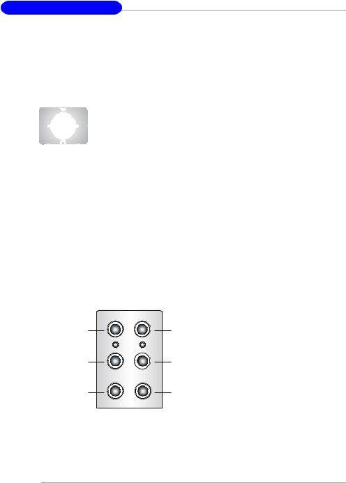
Audio Port Connectors
The left 3 audio jacks are for 2-channel mode for stereo speaker output: Line Out is a connector for Speakers or Headphones. Line In is used for external CD player, Tape player, or other audio devices. Mic is a connector for microphones.
However, there is an advanced audio application provided by Realtek CMI9880L to offer support for 7.1-channel audio operation and can turn rear audio connectors from 2-channel to 4-/5.1-/7.1- channel audio.
Line In |
Line Out |
MIC |
Surround Speaker
Out
(in 7.1CH / 5.1CH)
Center/Subwoofer
Speaker Out
( in 7.1CH / 5.1CH)
Back Surround
Speaker Out
(in 7.1CH)
2-12

Hardware Setup
Parallel Port Connector: LPT1
The mainboard provides a 25-pin female centronic connector as LPT. A parallel port is a standard printer port that supports Enhanced Parallel Port (EPP) and Extended Capabilities Parallel Port (ECP) mode.
|
13 |
1 |
|
|
|
|
|
14 |
|
|
|
|
|
|
|
25 |
|
||
|
|
Pin Definition |
|
|
PIN |
|
SIGNAL |
DESCRIPTION |
|
1 |
|
STROBE |
Strobe |
|
2 |
|
DATA0 |
Data0 |
|
3 |
|
DATA1 |
Data1 |
|
4 |
|
DATA2 |
Data2 |
|
5 |
|
DATA3 |
Data3 |
|
6 |
|
DATA4 |
Data4 |
|
7 |
|
DATA5 |
Data5 |
|
8 |
|
DATA6 |
Data6 |
|
9 |
|
DATA7 |
Data7 |
|
10 |
|
ACK# |
Acknowledge |
|
11 |
|
BUSY |
Busy |
|
12 |
|
PE |
PaperEnd |
|
13 |
|
SELECT |
Select |
|
14 |
|
AUTO FEED# |
AutomaticFeed |
|
15 |
|
ERR# |
Error |
|
16 |
|
INIT# |
Initialize Printer |
|
17 |
|
SLIN# |
Select In |
|
18 |
|
GND |
Ground |
|
19 |
|
GND |
Ground |
|
20 |
|
GND |
Ground |
|
21 |
|
GND |
Ground |
|
22 |
|
GND |
Ground |
|
23 |
|
GND |
Ground |
|
24 |
|
GND |
Ground |
|
25 |
|
GND |
Ground |
|
2-13
MS-7033 M-ATX Mainboard
Connectors
The mainboard provides connectors to connect to FDD, IDE HDD, case, LAN, USB Ports, IR module and CPU/System FAN.
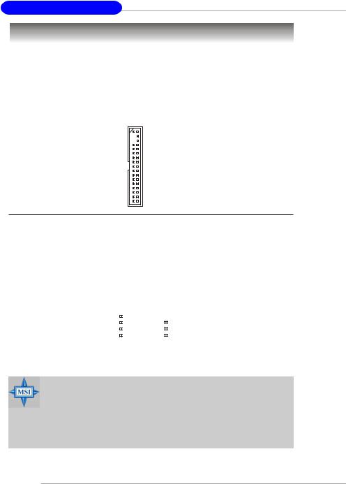
Floppy Disk Drive Connector: FDD1
The mainboard provides a standard floppy disk drive connector that supports 360K, 720K, 1.2M, 1.44M and 2.88M floppy disk types.
FDD1
Fan Power Connectors: CPU_FAN1 CPU_FAN2/SYS_FAN1
The CPU_FAN1 CPU_FAN2 (processor fan) and SYS_FAN1 (system fan1) support system cooling fan with +12V. It supports four/three-pin head connector.
When connecting the wire to the connectors, always take note that the red wire is the positive and should be connected to the +12V, the black wire is Ground and should be connected to GND. If the mainboard has a System Hardware Monitor chipset on-board, you must use a specially designed fan with speed sensor to take advantage of the CPU fan control.
Control |
|
|
|
|
|
|
GND |
SENSOR |
|
|
|
|
|
|
|
+12V |
|
|
|
|
|
|
+12V |
GND |
|
|
|
|
|
|
Sensor |
|
|
|
|
|
|
||
CPU_FAN1 |
SYSFAN1 |
||||||
CPU_FAN2 |
|
|
|
|
|||
MSI Reminds You...
1.Always consult the vendors for proper CPU cooling fan.
2.CPUFAN2 supports the fan control. Fan/heatsink with 3 or 4 fins are both available. Meanwhile, you can install Core Center utility (refer to Chapter 4 for details) that will automatically control the CPU fan speed according to the actual CPU temperature.
3.Please refer to the recommended CPU fans at Intel® official website.
2-14
Hardware Setup
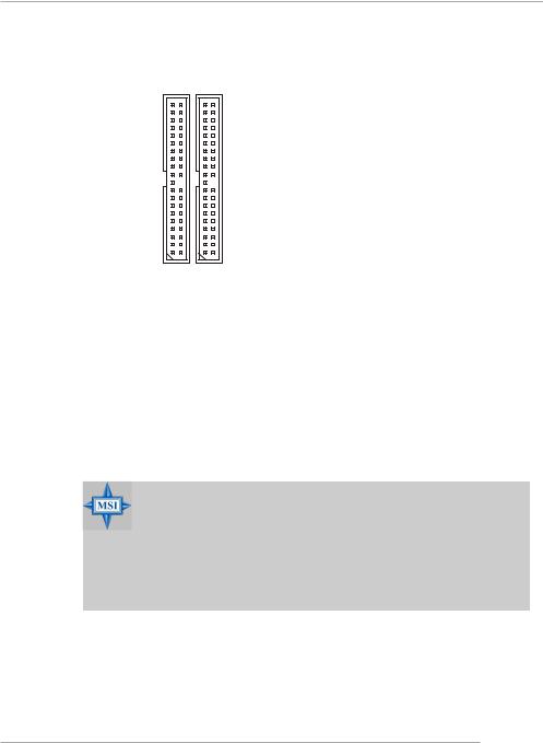
Hard Disk Connectors: IDE1 & IDE2 (optional)
The mainboard has 2 IDE ports and support the following function in the list.
IDE1/2 Definition
|
|
|
|
IDE |
VDMA |
Controller |
RAID |
ATAPI |
|
|
|
|
1 |
66/100 |
Intel ICH6 |
N/A |
Yes |
|
|
|
||||||
|
|
|
2 |
66/100/133 |
VIA VT6410 |
0/1 |
Yes |
|
|
|
|
|
|
|
|
|
|
IDE2 IDE1 (optional)
IDE1 (Primary IDE Connector)
The first hard drive should always be connected to IDE1. IDE1 can connect a Master and a Slave drive. You must configure second hard drive to Slave mode by setting the jumper accordingly.
IDE2 (Secondary IDE Connector)(optional)
IDE2 can also connect a Master and a Slave drive.
The default setting of IDE2 is standard IDE. RAID function can be enabled by BIOS setting.
MSI Reminds You...
If you install two hard disks on cable, you must configure the second drive to Slave mode by setting its jumper. Refer to the hard disk documentation supplied by hard disk vendors for jumper setting instructions.
If you want to use RAID function, please make a RAID driver from
Driver CD-ROM before installing OS.
2-15

MS-7033 M-ATX Mainboard
Serial ATA HDD Connectors: SATA1 & SATA2
The mainboard provides dual high-speed Serial ATA interface ports. The ports support 1st generation Serial ATA data rates of 150MB/s and are fully compliant with
Serial ATA 1.0 specifications. Each Serial ATA connector can connect to 1 hard disk drive.
SATA1/SATA2 Pin Definition
|
|
|
|
|
|
|
|
|
|
|
|
|
|
SATA2 |
|
|
|
|
1 |
7 |
|
|
|
|
|
|
PIN |
SIGNAL |
PIN |
SIGNAL |
|||||||
|
|
|
|
|
SATA1 |
1 |
GND |
2 |
TXP |
|||||||||
7 |
1 |
|
|
|
|
|
|
3 |
TXN |
4 |
GND |
|||||||
|
|
|
|
|
|
5 |
RXN |
6 |
RXP |
|||||||||
|
|
|
|
|
|
|
|
|
|
|
|
|
|
|
||||
|
|
|
|
|
|
|
|
|
|
|
|
|
|
|
7 |
GND |
|
|
|
|
|
|
|
|
|
|
|
|
|
|
|
|
|
|
|
|
|
Serial ATA cable
Take out the dust cover and connect to the hard disk devices
Connect to serial ATA ports
MSI Reminds You...
Please do not fold the serial ATA cable in a 90-degree angle, which will cause the loss of data during the transmission.
2-16

Hardware Setup
Front Panel Connectors: JFP1 & JFP2
The mainboard provides two front panel connectors for electrical connection to the front panel switches and LEDs. JFP1 is compliant with Intel® Front Panel I/O Connectivity Design Guide.
|
|
|
|
Speaker |
|
|
|
|
|
|
Power Power |
|
||||||||||||||||
|
|
|
|
|
|
|
|
|
|
LED |
|
|
Switch |
|
||||||||||||||
JFP2 |
2 |
|
|
|
|
|
|
|
|
|
8 |
|
|
|
2 |
|
|
|
|
|
|
|
|
|
10 |
JFP1 |
||
|
|
|
|
|
|
|
|
|
|
|
|
|
|
|
|
|
|
|
|
|||||||||
|
|
|
|
|
|
|
|
|
|
|
|
|
|
|
|
|
|
|
|
|||||||||
1 |
|
|
|
|
|
|
|
|
|
|
|
|
|
|
|
|
|
|
|
|
|
|||||||
|
|
|
|
|
|
|
|
|
|
7 |
|
|
|
1 |
|
|
|
|
|
|
|
|
|
9 |
|
|||
|
|
|
|
|
|
|
|
|
|
|
|
|
|
|
|
|
|
|
||||||||||
|
|
|
|
Power |
|
|
|
|
HDD |
Reset |
|
|||||||||||||||||
|
|
|
|
LED |
|
|
|
|
LED |
Switch |
|
|||||||||||||||||
|
|
|
|
|
|
|
|
|
|
|
|
JFP1 Pin Definition |
|
|
|
|
|
|
|
|
|
|
|
|
|
|||
|
|
|
|
|
|
|
|
|
|
|
|
|
|
|
|
|
|
|
|
|
|
|||||||
PIN |
|
|
SIGNAL |
|
DESCRIPTION |
|
|
|
|
|
|
|
|
|
|
|
|
|
||||||||||
1 |
|
|
HD_LED_P |
Hard disk LED pull-up |
|
|
|
|
|
|
|
|
||||||||||||||||
2 |
|
|
FP PWR/SLP |
MSG LED pull-up |
|
|
|
|
|
|
|
|
||||||||||||||||
3 |
|
|
HD_LED_N |
Hard disk active LED |
|
|
|
|
|
|
|
|
||||||||||||||||
4 |
|
|
FP PWR/SLP |
MSG LED pull-up |
|
|
|
|
|
|
|
|
||||||||||||||||
5 |
|
|
RST_SW_N |
Reset Switch low reference pull-down to GND |
||||||||||||||||||||||||
6 |
|
|
PWR_SW_P |
Power Switch high reference pull-up |
|
|||||||||||||||||||||||
7 |
|
|
RST_SW_P |
Reset Switch high reference pull-up |
|
|||||||||||||||||||||||
8 |
|
|
PWR_SW_N |
Power Switch low reference pull-down to GND |
||||||||||||||||||||||||
9 |
|
|
RSVD_DNU |
Reserved. Do not use. |
|
|
|
|
|
|
|
|
||||||||||||||||
|
|
|
|
|
|
|
|
|
|
|
|
|
|
|
|
|
|
|
|
|
|
|
|
|||||
|
|
|
|
|
|
|
|
|
|
|
|
JFP2 Pin Definition |
|
|
|
|
|
|
|
|
||||||||
|
|
|
|
|
|
|
|
|
|
|
|
|
|
|
|
|
|
|
|
|
||||||||
|
|
|
|
|
|
|
PIN |
SIGNAL |
|
PIN |
|
SIGNAL |
|
|
|
|
|
|
|
|
||||||||
|
|
|
|
|
1 |
|
|
|
|
GND |
|
2 |
|
SPK- |
|
|
|
|
|
|
|
|
||||||
|
|
|
|
3 |
|
|
|
|
SLED |
|
4 |
|
BUZ+ |
|
|
|
|
|
|
|
|
|||||||
|
|
|
|
5 |
|
|
|
|
PLED |
|
6 |
|
BUZ- |
|
|
|
|
|
|
|
|
|||||||
|
|
|
|
7 |
|
|
|
|
NC |
|
8 |
|
SPK+ |
|
|
|
|
|
|
|
|
|||||||
|
|
|
|
|
|
|
|
|
|
|
|
|
|
|
|
|
|
|
|
|
|
|
|
|
|
|
|
|
2-17
 Loading...