


FCC-B Radio Frequency Interference Statement
This equipment has been tested and found to comply with the limits for a class B digital device, pursuant to part 15 of the FCC rules. These limits are designed to provide reasonable protection against harmful interference when the equipment is operated in a commercial environment. This equipment generates, uses and can radiate radio frequency energy and, if not installed and used in accordance with the instruction manual, may cause harmful interference to radio communications. Operation of this equipment in a residential area is likely to cause harmful interference, in which case the user will be required to correct the interference at his own expense.
Notice 1
The changes or modifications not expressly approved by the party responsible for compliance could void the user’s authority to operate the equipment.
Notice 2
Shielded interface cables and A.C. power cord, if any, must be used in order to comply with the emission limits. VOIR LA NOTICE D’NSTALLATION AVANT DE RACCORDER AU RESEAU.
Micro-Star International
MS-7113
This device complies with Part 15 of the FCC Rules. Operation is subject to the following two conditions:
(1)this device may not cause harmful interference, and
(2)this device must accept any interference received, including interference that may cause undesired operation
G52-M7113X1
i
Copyright Notice
The material in this document is the intellectual property of MICRO-STAR INTERNATIONAL. We take every care in the preparation of this document, but no guarantee is given as to the correctness of its contents. Our products are under continual improvement and we reserve the right to make changes without notice.
Trademarks
All trademarks are the properties of their respective owners.
AMD, Athlon™ Athlon™XP, Thoroughbred™ and Duron™ are registered trademarks of AMD Corporation. Intel® and Pentium® are registered trademarks of Intel Corporation.
PS/2 and OS® 2 are registered trademarks of International Business Machines Corporation. Microsoft® is a registered trademark of Microsoft Corporation. Windows® 98/2000/NT/XP are registered trademarks of Microsoft Corporation.
NVIDIA, the NVIDIA logo, DualNet, and nForce are registered trademarks or trademarks of NVIDIA Corporation in the United States and/or other countries.
Netware® is a registered trademark of Novell, Inc.
Award® is a registered trademark of Phoenix Technologies Ltd. AMI® is a registered trademark of American Megatrends Inc.
Kensington and MicroSaver are registered trademarks of the Kensington Technology Group.
PCMCIA and CardBus are registered trademarks of the Personal Computer Memory Card International Association.
Revision History
Revision |
Revision History |
Date |
V1.0 |
First release for PCB v1.X with SiS® 649 & SiS® 965L |
Feb. 2005 |
ii

Safety Instructions
1.Always read the safety instructions carefully.
2.Keep this User Manual for future reference.
3.Keep this equipment away from humidity.
4.Lay this equipment on a reliable flat surface before setting it up.
5.The openings on the enclosure are for air convection hence protects the equipment from overheating. Do not cover the openings.
6.Make sure the voltage of the power source and adjust properly 110/220V before connecting the equipment to the power inlet.
7.Place the power cord such a way that people can not step on it. Do not place anything over the power cord.
8.Always Unplug the Power Cord before inserting any add-on card or module.
9.All cautions and warnings on the equipment should be noted.
10.Never pour any liquid into the opening that could damage or cause electrical shock.
11.If any of the following situations arises, get the equipment checked by a service personnel:
-The power cord or plug is damaged.
-Liquid has penetrated into the equipment.
-The equipment has been exposed to moisture.
-The equipment does not work well or you can not get it work according to User Manual.
-The equipment has dropped and damaged.
-The equipment has obvious sign of breakage.
12.Do not leave this equipment in an environment unconditioned, storage temperature above 60° C (140°F), it may damage the equipment.
CAUTION: Danger of explosion if battery is incorrectly replaced. Replace only with the same or equivalent type recommended by the manufacturer.
iii
|
Table of Content |
English..................................................................... |
1 |
Français................................................................... |
15 |
Deutsch.................................................................... |
29 |
................................................................... |
45 |
................................................................... |
59 |
iv
Introduction
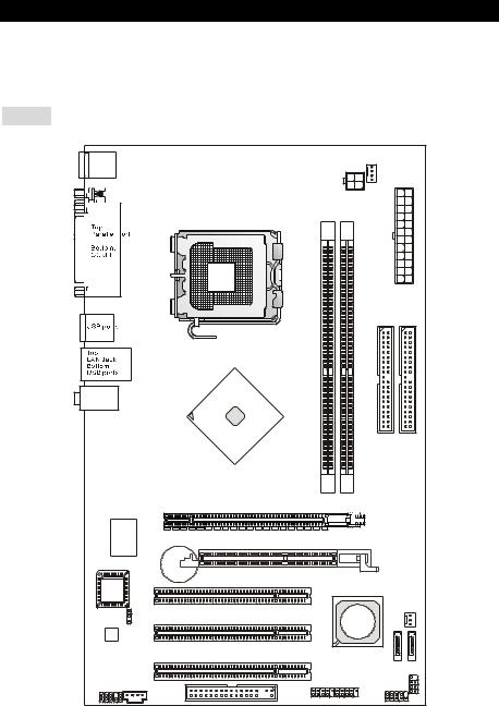
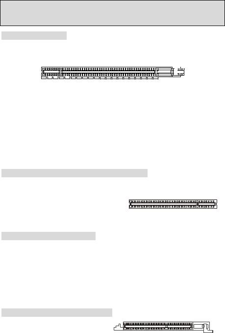
Thank you for choosing the 649 Neo-V (MS-7113 v1.X) Series ATX mainboard. The 649 Neo-V Series is based on SiS® 649 & SiS® 965L chipsets for optimal system efficiency. Designed to fit the advanced Intel® P4 Prescott 533/ 800MHz processors in LGA775 package, the 649 Neo-V Series delivers a high performance and professional desktop platform solution.
Layout
T: mouse |
|
|
|
|
|
|
B: keyboard |
|
|
|
|
CPUFAN1 |
|
|
|
|
|
|
||
|
|
|
|
JPW1 |
|
|
|
|
|
|
|
|
ATX1 |
|
|
|
|
|
IDE2 |
IDE1 |
|
|
|
DIMM1 |
DIMM2 |
|
|
T:Line-In |
|
|
|
|
|
|
M:Line-Out |
|
|
|
|
|
|
B:Mic |
|
|
|
|
|
|
|
|
|
SiS |
|
|
|
|
|
|
649 |
|
|
|
|
|
|
Chipset |
|
|
|
|
|
|
PCI_E 1 |
|
|
|
Winbond |
|
|
|
|
|
|
W83627THF |
|
AGR Slot |
|
|
|
|
|
|
BATT |
|
|
|
|
|
|
+ |
PCI Slot 1 |
|
|
|
BIOS |
|
|
|
|
|
|
|
|
|
|
|
|
|
|
JBAT1 |
|
|
SiS |
SYSFAN1 |
|
|
|
PCI Slot 2 |
|
|
||
Codec |
|
965L |
|
|
||
|
|
|
|
|||
|
|
|
Chipset |
|
||
|
|
|
|
|
||
|
|
|
PCI Slot 3 |
|
SATA2 |
|
|
|
|
|
|
SATA1 |
|
|
|
|
|
|
|
|
JAUD1 |
CD1 |
|
JUSB1 JUSB2 |
JFP2 |
||
|
FDD1 |
|
JFP1 |
|
||
|
|
|
|
|
||
|
|
|
|
|
|
|
|
|
|
1 |
|
|
|

Specifications
CPU
•Supports Intel Pentium 4 / Celeron D Prescott processors in LGA775 package.
•Supports up to Pentium 4 3XX, 5XX and 6XX sequence processor or higher speed.
•Supports Intel Hyper-Threading Technology.
•For the latest information about CPU, please visit http://www.msi.com.tw/program/products/mainboard/mbd/pro_mbd_cpu_support.php
Chipset
•SiS® 649 chipset
-Supports FSB 533/ 800 MHz.
-Supports PCI Express x 16 interface.
-Supports DDR333/ DDR400 memory interface.
•SiS® 965L chipset
-Hi-Speed USB (USB2.0) controller, 480Mb/sec, 8 ports.
-2 Serial ATA ports with transfer rate up to 1.5Gb/s
-2 channel Ultra ATA 66/100/ 133 bus Master IDE controller.
-PCI Master v2.3, I/O APIC.
-Supports both ACPI and legacy APM power management.
Main Memory
•Supports two unbuffered DIMM of DDR SDRAM.
•Supports up to 2GB memory size without ECC.
•Supports DDR333/ DDR400 MHz.
(For the updated supporting memory modules, please visit http://www.msi.com.tw/program/products/mainboard/mbd/pro_mbd_trp_list.php )
Slots
•One PCI Express x16 slot (supports PCI Express Bus specification v1.0a compliant).
•One AGR (Advance Graphics Riser) slot for compatible AGP VGA cards.
•Three PCI 2.3 32-bit PCI bus slots (support 3.3v/5v PCI bus interface).
On-Board IDE
•One Ultra DMA 66/100/133 IDE controller integrated in 965L.
-Supports PIO, Bus Master operation modes
-Can connect up to four Ultra ATA drives.
•Serial ATA/150 controller integrated in 965L
-Up to 150MB/sec transfer speeds.
-Can connect up to two Serial ATA drives.
2
On-Board Peripherals
•On-Board Peripherals includes:
-1 floppy port supports 1 FDDs with 360K, 720K, 1.2M, 1.44M and 2.88Mbytes.
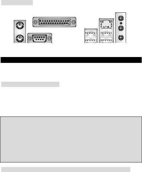
-1 serial ports (Rear * 1) and 1 parallel port supports SPP/EPP/ECP mode.
-8 USB 2.0 ports (Rear * 4/ Front * 4).
-3 audio (Line-In/Line-Out/Mic) jacks.
-1 RJ-45 LAN Jack.
Audio
•AC97 link controller integrated in 965L chipset.
•6-channel audio codec ADI AD1888.
-Compliance with AC97 v2.3 Spec.
-Meet PC2001 audio performance requirement.
LAN
•Broadcom AC131
-Integrated Fast Ethernet PHY.
-Supports 10Mb/s and 100Mb/s.
-Compliance with PCI 2.2.
-Supports ACPI Power Management.
BIOS
•The mainboard BIOS provides “Plug & Play” BIOS which detects the peripheral devices and expansion cards of the board automatically.
•The mainboard provides a Desktop Management Interface (DMI) function that records your mainboard specifications.
Dimension
•ATX Form Factor: 30.5 cm x 18.5 cm.
Mounting
•6 mounting holes.
Others
•Supports PS/2 Keyboard/Mouse
•Hardware monitor is to monitor temperature and voltage.
3
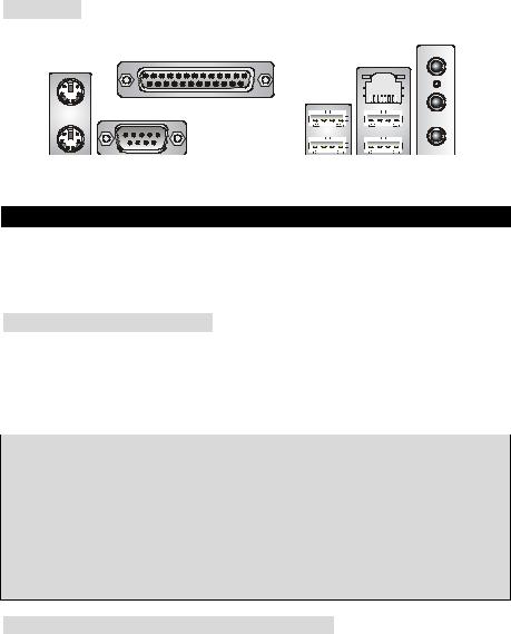
Rear Panel
The rear panel provides the following connectors:
Line ln
Parallel port |
LAN |
Mouse |
|
|
USB ports |
|
|
|
|
|
|
|
|
|
|
|
|
|
|
|
|
|
|
|
|
|
|
|
|
|
|
|
|
|
|
|
|
|
|
|
|
|
|
|
|
|
|
|
|
|
|
|
|
|
|
|
|
|
|
|
|
|
|
|
|
|
|
|
|
|
|
|
|
|
|
|
|
|
|
|
|
|
|
|
|
|
|
|
|
|
|
|
|
|
|
|
|
|
|
|
|
|
|
|
|
|
|
|
|
|
Keyboard COM port |
|
|
|
|
|
|
|
|
USB ports Line Out |
|||||||||||
|
|
|
|
|
|
|
|
|
|
|
|
|
|
|
|
|
|
|
MIC |
|
Hardware Setup
This chapter tells you how to install the CPU, memory modules, and expansion cards, as well as how to setup the jumpers on the mainboard. It also provides the instructions on connecting the peripheral devices, such as the mouse, keyboard, etc. While doing the installation, be careful in holding the components and follow the installation procedures.
Central Processing Unit: CPU
The mainboard supports Intel Pentium 4 / Celeron D Prescott processor. The mainboard uses a CPU socket called LGA775. When you are installing the CPU, make sure to install the cooler to prevent overheating. If you do not have the CPU cooler, contact your dealer to purchase and install them before turning on the computer. For the latest information about CPU, please visit http://www.msi.com.tw/program/products/mainboard/mbd/pro_mbd_cpu_support.php
MSI Reminds You...
Overheating
Overheating will seriously damage the CPU and system, always make sure the cooling fan can work properly to protect the CPU from overheating.
Overclocking
This motherboard is designed to support overclocking. However, please make sure your components are able to tolerate such abnormal setting, while doing overclocking. Any attempt to operate beyond product specifications is not recommended. We do not guarantee the damages or risks caused by inadequate operation or beyond product specifications.
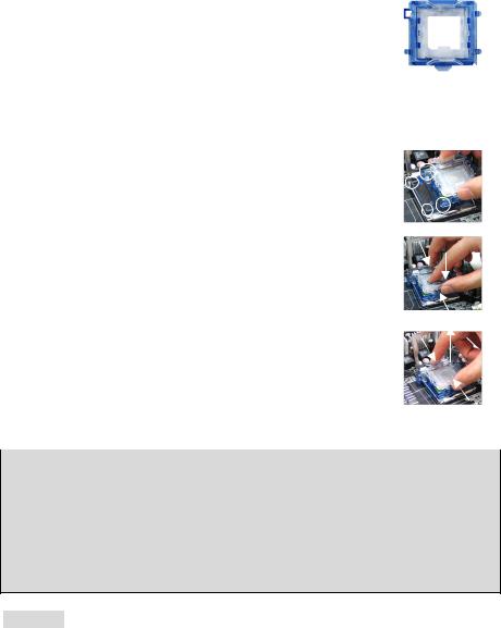
LGA775 CPU Installation (CPU Clip is optional)
When you are installing the CPU, make sure the CPU has a cooler attached on the top to prevent overheating. If you do not have the cooler, contact your dealer to purchase and install them before turning on the computer. Meanwhile, do not forget to apply some silicon heat transfer compound on CPU before installing the cooler for better heat dispersion.
Follow the steps below to install the CPU & cooler correctly. Wrong installation will cause the damage of your CPU & mainboard.
4
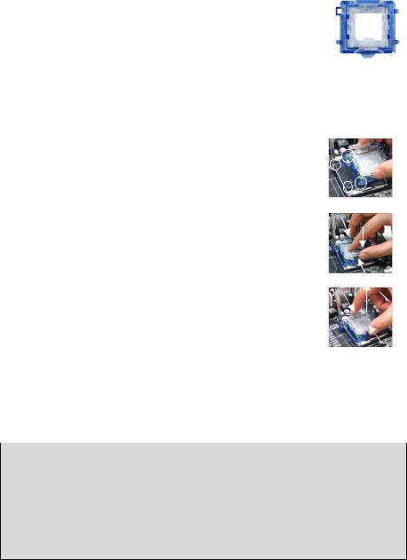
1.The CPU has a land side cover on the bottom to protect the CPU contact from damage. Rotate it to make the pin 1 indicator (yellow triangle) in the left-bottom
corner. The availability of it depends on the CPU packing.
2.Take out the accompanying CPU Clip (shown in the right) and rotate it for the same direction as the CPU (Pin 1 indicator is in the left-bottom corner).
3.Use 2 hands to remove the land side cover (if any). Please note not to touch the pins.
4.Align the two pin 1 indicators (the triangles on the CPU & the CPU Clip), and use the CPU Clip to clip the CPU up, pressing the clips on both sides to the center, as the arrows shown.
5.The CPU has a plastic cap on it to protect the contact from damage. Before you have installed the CPU, always cover it to protect the socket pin.
6.Remove the cap from lever hinge side. The pins of socket reveal.
7. Lift the load lever up and open the load plate.
8. Correctly align the triangle of CPU Clip with the CPU chamfer, and the square on the CPU Clip to the hook of the socket.
9.Use your thumb and the middle fingers to push the clips to release the CPU, then press down the CPU with your index finger to allow the whole module to be installed onto the CPU socket.
10.The CPU is installed well on the CPU socket.
11.Visually inspect if the CPU is seated well into the socket, then remove the CPU Clip with 2 fingers. Then cover the load plate onto the package.
12.Press down the load lever lightly onto the load plate, and then secure the lever with the hook under retention tab.
13.Align the holes on the mainboard with the cooler. Push down the cooler until its four clips get wedged into the holes of the mainboard.
14.Press the four hooks down to fasten the cooler. Then rotate the locking switch (refer to the correct direction marked on it) to lock the hooks.
15.Turn over the mainboard to confirm that the clip-ends are correctly inserted.
Note: If you want to uninstall the CPU, align the 4 points (see Point 8 for details) again and push the clip to lift up the CPU.
MSI Reminds You...
1.Confirm if your CPU cooler is firmly installed before turning on your system.
2.Check the information in H/W Monitor in BIOS for the CPU temperature.
3.Do not touch the CPU socket pins to avoid damaging.
4.Whenever CPU is not installed, always protect your CPU socket pin with the plastic cap covered to avoid damaging.
5.Please note that the mating/unmating durability of the CPU is 20 cycles. Therefore we suggest you do not plug/unplug the CPU too often.
5
Memory
The mainboard provides two 184-pin unbuffered DDR333 / DDR400 DDR SDRAM, and supports the memory size up to 2GB. To operate properly, at least one DIMM module must be installed. (For the updated supporting memory modules, please visit http://www.msi.com.tw/program/products/mainboard/mbd/pro_mbd_trp_list.php)
Install at least one DIMM module on the slots. Memory modules can be installed on the slots in any order. You can install either singleor double-sided modules to meet your own needs.
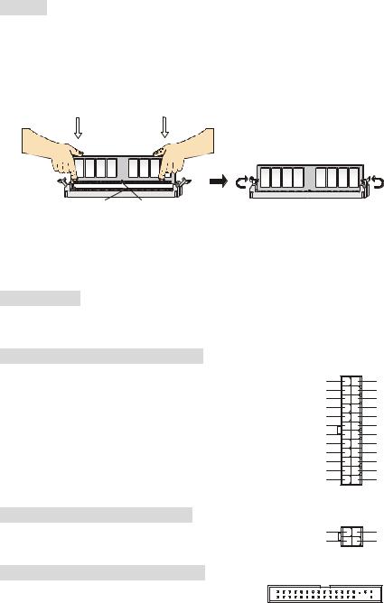
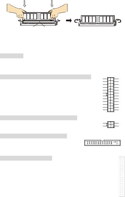
Installing DDR Modules
Volt Notch
1.The DDR DIMM has only one notch on the center of module. The module will only fit in the right orientation.
2.Insert the DIMM memory module vertically into the DIMM slot. Then push it in until the golden finger on the memory module is deeply inserted in the socket.
3.The plastic clip at each side of the DIMM slot will automatically close.
Power Supply
The mainboard supports ATX power supply for the power system. Before inserting the power supply connector, always make sure that all components are installed properly to ensure that no damage will be caused. A 300W or above power supply is suggested.
ATX 24-Pin Power Connector: ATX1
This connector allows you to connect an ATX 24-pin power supply. To connect the ATX 24-pin power supply, make sure the plug of the power supply is inserted in the proper orientation and the pins are aligned. Then push down the power supply firmly into the connector. You may use the 20-pin ATX power supply power supply as you like. If you’d like to use the 20-pin ATX power supply, please plug your power supply along with pin 1 & pin 13 (refer to the image at the right hand). There is also a foolproof design on pin 11, 12, 23 & 24 to avoid wrong installation.
+3.3V -12V GND PS-ON# GND GND GND Res +5V +5V +5V GND
13 |
1 |
|
+3.3V |
|
+3.3V |
|
GND |
|
+5V |
|
GND |
|
+5V |
|
GND |
|
PWR OK |
|
5VSB |
|
+12V |
|
+12V |
|
NC |
24 |
12 |
ATX 12V Power Connector: JPW1
This 12V power connector is used to provide power to the CPU.
Floppy Disk Drive Connector: FDD1
The mainboard provides a standard floppy disk drive connector that supports 360K, 720K, 1.2M, 1.44M and 2.88M floppy disk types.
4 |
2 |
12V |
GND |
12V |
GND |
3 |
1 |
6
IDE Connectors: IDE1/ IDE2
The mainboard has a 32-bit Enhanced PCI IDE and Ultra DMA 66/100/133 controller that provides PIO mode 0~4, Bus Master, and Ultra DMA 66/100/133 function. You can connect up to four IDE interface devices as Hard Disk, CD-ROM, 120MB Floppy, etc.
The first hard drive should always be connected to IDE1. IDE1 can connect a Master and a Slave drive. You must configure second hard drive to Slave mode by setting the jumper accordingly.
MSI Reminds You...
If you install two hard disks on cable, you must configure the second drive to Slave mode by setting its jumper. Refer to the hard disk documentation supplied by hard disk vendors for jumper setting instructions.
Serial ATA Connectors controlled by SiS 965L: SATA1/SATA2
The Southbridge of this mainboard is SiS 965L, which supports two serial connectors SATA1~2.
SATA1~2 are dual high-speed Serial ATA interface ports. Each supports 1st generation serial ATA data rates of 150 MB/s. All SATA connectors are fully compliant with Serial ATA 1.0 specifications. Each Serial ATA connector can connect to 1 hard disk device.
1 


7
MSI Reminds You...
Please do not fold the serial ATA cable in a 90-degree angle, which will cause the loss of data during transmission.
CD-In Connector: JCD1 |
|
|
|
|
|
|
GND |
||||||||||
The connector is for CD-ROM audio connector. |
|
|
|
||||||||||||||
|
|
|
|
|
|
|
|
|
|
|
|
|
|
||||
|
|
|
|
|
|
|
|
|
|
|
|
|
|
||||
|
L |
|
|
|
|
|
|
|
|
|
|
|
|
|
|
|
R |
|
|
|
|
|
|
|
|
|
|
|
|
|
|
|
|
||
Fan Power Connectors: CPUFAN1/SYSFAN1
The 4-pin CPUFAN1 (processor fan) and 3-pin SYSFAN1 (system fan) support system cooling fan with +12V. CPUFAN1 can support threeor four-pin head connector. When
connecting the wire to the connectors, always take note that the red wire is the positive and should be connected to the +12V, the black wire is Ground and should be connected to GND. If the mainboard has a System Hardware Monitor chipset on-board, you must use a specially designed fan with speed sensor to take advantage of the CPU fan control.
MSI Reminds You...
Always consult the vendors for proper CPU cooling fan.
7

Front Panel Connectors: JFP1/JFP2
The mainboard provides two front panel connectors for electrical connection to the front panel switches and LEDs. JFP1 is compliant with Intel Front Panel I/O Connectivity Design Guide.
Power Power |
|
|
|
LED Switch |
|
8 7 |
|
2 |
10 |
||
|
|||
1 |
9 Speaker |
Power |
|
HDD Reset |
|
LED |
|
LED Switch |
|
2 1 |
JFP1 JFP2
Front Panel Audio Connector: JAUD1
The front panel audio connector allows you to connect to the front panel audio and is compliant with Intel® Front Panel I/O Connectivity Design Guide.
AUD_RET_R
AUD_VCC Key
(2)AUD_GND 


 AUD_RET_L(10) (1)AUD_MIC


 AUD_FPOUT_L(9)
AUD_MIC_BIAS HP_ON
AUD_FPOUT_R
MSI Reminds You...
If you do not want to connect to the front audio header, pins 5 & 6, 9 & 10 have to be jumpered in order to have signal output directed to the rear audio ports. Otherwise, the Line-Out connector on
2 |
10 |
the back panel will not function. 1 |
9 |
Front USB Connector: JUSB1/ JUSB2
The mainboard provides two standard USB 2.0 pin |
|
|
|
|
|
USB1+ |
|||||||||||||
headers JUSB1 & JUSB2. USB2.0 technology increases |
|
USB1- |
|
GND |
|||||||||||||||
(2)VCC |
|
|
|
|
|
|
|
|
|
|
|
|
|
|
|
|
|
USB0C(10) |
|
data transfer rate up to a maximum throughput of 480Mbps, |
|
|
|
|
|
|
|
|
|
|
|
|
|
|
|
|
|
||
(1)VCC |
|
|
|
|
|
|
|
|
|
|
|
|
|
|
|
|
|
Key(9) |
|
which is 40 times faster than USB 1.1, and is ideal for |
|
|
|
|
|
|
|||||||||||||
|
USB0- |
|
GND |
||||||||||||||||
connecting high-speed USB interface peripherals such as |
|
|
|
|
|
USB0+ |
|||||||||||||
USB HDD, digital cameras, MP3 players, printers, modems and the like.
MSI Reminds You...
Please note that the pins of VCC & GND must be connected correctly, or it may cause some damage.
Clear CMOS Jumper: JBAT1
There is a CMOS RAM on board that has a power supply from external battery to keep the data
of system configuration. With the CMOS RAM, the system |
1 |
1 |
|
|
1 |
|
|
can automatically boot OS every time it is turned on. If you |
|
|
|
|
|||
2 |
2 |
|
|
2 |
|
|
|
want to clear the system configuration, use the JBAT1 |
3 |
3 |
|
|
3 |
|
|
|
|
|
|
||||
|
Keep Data |
Clear Data |
|||||
(Clear CMOS Jumper) to clear data. Follow the instructions |
|
||||||
|
|
|
|
|
|
|
|
in the image to clear the data.
8
MSI Reminds You...
You can clear CMOS by shorting 2-3 pin while the system is off. Then return to 1-2 pin position. Avoid clearing the CMOS while the system is on; it will damage the mainboard.
PCI Express x16 Slot
The PCI Express x16 slot, as a high-bandwidth, low pin count, serial, interconnect technology, support Intel highest performance desktop platforms utilizing the Intel Pentium 4 processor with HT Technology.
PCI Express architecture provides a high performance I/O infrastructure for Desktop Platforms with transfer rates starting at 2.5 Giga transfers per second over a PCI Express x1 lane for Gigabit Ethernet, TV Tuners, 1394 controllers, and general purpose I/O. Also, desktop platforms with PCI Express Architecture will be designed to deliver highest performance in video, graphics, multimedia and other sophisticated applications. Moreover, PCI Express architecture provides a high performance graphics infrastructure for Desktop Platforms doubling the capability of existing AGP8x designs with transfer rates of 4.0 GB/s over a PCI Express x16 lane for graphics controllers, while PCI Express x1 supports transfer rate of 250 MB/s.
You can insert the expansion cards to meet your needs. When adding or removing expansion cards, make sure that you unplug the power supply first.
PCI (Peripheral Component Interconnect) Slots
The PCI slots allow you to insert the expansion cards to meet your needs. When adding or removing expansion cards, make sure that you unplug the power supply first. Meanwhile, read the documentation for the expansion card to make
any necessary hardware or software settings for the expansion card, such as jumpers, switches or BIOS
configuration.
PCI Interrupt Request Routing
The IRQ, abbreviation of interrupt request line and pronounced I-R-Q, are hardware lines over which devices can send interrupt signals to the microprocessor. The PCI IRQ pins are typically connected to the PCI bus INT A# ~ INT D# pins as follows:
|
Order1 |
Order2 |
Order3 |
Order4 |
|
|
|
|
|
PCI Slot 1 |
INT B# |
INT C# |
INT D# |
INT A# |
|
|
|
|
|
PCI Slot 2 |
INT C# |
INT D# |
INT A# |
INT B# |
|
|
|
|
|
PCI Slot 3 |
INT D# |
INT A# |
INT B# |
INT C# |
|
|
|
|
|
AGR (Advance Graphics Riser) Slot
The AGR (Advance Graphics Riser) slot is a special design that only supports compatible AGP VGA cards.
9

Compatible VGA Card List
No. |
VGA CARD |
Model name |
VGA Chip |
VGA Memory |
|
MS-7113 |
|
|
|
|
|||||
Vender |
|
|
|
||||
Result |
|
Driver Ver. |
|||||
|
|
|
|
|
|||
|
|
|
|
|
|
||
|
|
|
|
|
|
|
|
1 |
Alvatron |
FX5700U |
GeForce FX5700 Ultra |
128MB/DDR SDRAM |
Pass |
|
6.14.10.7125 |
2 |
ATI |
Fire GL 8800 |
Fire GL 8800 |
128MB/SDRAM |
Pass |
|
6.12.10.3056 |
3 |
ATI |
Radeon 9800 XT |
Radeon 9800 XT |
256MB/DDR SDRAM |
Pass |
|
6.14.10.6476 |
4 |
GAINWARD |
GFX 5900 Ultra |
GeForce 4 FX 5900 U |
256MB/DDR SDRAM |
Pass |
|
6.14.10.7125 |
5 |
Gigabyte |
GV-R9200 |
Radeon 9200 |
128MB/DDR SDRAM |
Pass |
|
6.14.10.6512 |
6 |
Gigabyte |
GV-N57L128D |
GeForce FX5700LE |
128MB/DDR SDRAM |
Pass |
|
6.14.10.7125 |
7 |
Leadtek |
Winfast A360LE TD |
GeForce FX5700LE |
128MB/DDR SDRAM |
Pass |
|
6.14.10.7125 |
8 |
Leadtek |
Winfast A400GT TDH |
GeForce 6800GT |
256MB/DDR SDRAM |
Pass |
|
6.14.10.7125 |
9 |
MSI |
MS-8863 |
GeForce 4 MX 460 |
64MB/SDRAM |
Pass |
|
6.14.10.2958 |
10 |
MSI |
MS-8907 |
GeForce FX 5200 |
64MB/DDR SDRAM |
Pass |
|
6.14.10.7125 |
11 |
MSI |
MS-8911 |
GeForce FX 5200 |
128MB/DDR SDRAM |
Pass |
|
6.14.10.7125 |
12 |
MSI |
MS-8919 |
GeForce FX 5200 |
128MB/DDR SDRAM |
Pass |
|
6.14.10.7125 |
13 |
MSI |
MS-8923 |
GeForce FX 5200 Ultra |
128MB/DDR SDRAM |
Pass |
|
6.14.10.7125 |
14 |
MSI |
MS-8929 |
GeForce FX 5900 |
128MB/DDR SDRAM |
Pass |
|
6.14.10.7125 |
15 |
MSI |
MS-8931 |
GeForce FX 5600 Ultra |
128MB/DDR SDRAM |
Pass |
|
6.14.10.7125 |
16 |
MSI |
MS-8936 |
GeForce4 MX4000 |
64MB/DDR SDRAM |
Pass |
|
6.14.10.6681 |
17 |
MSI |
MS-8936 |
GeForce FX5500 |
128MB/DDR SDRAM |
Pass |
|
6.14.10.7125 |
18 |
MSI |
MS-8946 |
GeForce FX 5950 Ultra |
256MB/DDR SDRAM |
Pass |
|
6.14.10.7125 |
19 |
MSI |
MS-8959 |
GeForce FX5700LE |
128MB/DDR SDRAM |
Pass |
|
6.14.10.7125 |
20 |
MSI |
MS-8975 |
Nvidia GeForce 6800 |
128MB/DDR SDRAM |
Pass |
|
6.14.10.7125 |
21 |
Unika |
FX5200 SP5208 |
GeForce FX5200 |
64MB/DDR SDRAM |
Pass |
|
6.14.10.7125 |
22 |
MSI |
MS-8952 |
ATI Radeon 9250 |
128MB/DDR SDRAM |
Pass |
|
6.14.10.6512 |
23 |
Power Color |
R92U-LC3 |
Radeon 9250 |
128MB/DDR SDRAM |
Pass |
|
6.14.10.6505 |
24 |
Power Color |
RV6DE-NB3 |
Radeon 7000 |
64MB/DDR SDRAM |
Pass |
|
6.13.10.6476 |
25 |
ATI |
Radeon LE |
Radeon LE DDR |
32MB/DDR SGRAM |
Pass |
|
6.13.10.6153 |
26 |
ATI |
Radeon 7500 LE |
Radeon DDR |
64MB/SDRAM |
Pass |
|
6.13.10.6153 |
27 |
ATI |
Fire GL 8700 |
Fire GL 8700 |
64MB/DDR SDRAM |
Pass |
|
6.12.10.3051 |
28 |
ATI |
Radeon 9000 Pro |
Radeon DDR |
64MB/DDR SDRAM |
Pass |
|
6.14.10.6458 |
29 |
ATI |
Radeon 9500 |
Radeon 9500 |
64MB/DDR SDRAM |
Pass |
|
6.14.10.6458 |
30 |
ATI |
Radeon 9700 |
Radeon 9700 |
128MB/DDR SDRAM |
Pass |
|
6.14.10.6458 |
31 |
ASUS |
AGP-V7700 Deluxe |
GeForce 2 GTS |
32MB/DDR SGRAM |
Pass |
|
6.14.10.2958 |
32 |
ASUS |
V8440 |
GeForce 4 Ti 4400 |
128MB/SDRAM |
Pass |
|
6.14.10.2958 |
33 |
ASUS |
V8460 Ultra |
GeForce 4 Ti 4600 |
128MB/SDRAM |
Pass |
|
6.14.10.2958 |
34 |
Creative |
3D Blaster 5 RX9700 |
Radeon 9700 |
128MB/SGRAM |
Pass |
|
6.14.10.6458 |
|
|
Pro |
|
|
|
|
|
35 |
ELSA |
Gladiac 517 SV |
GeForce 4 MX420 |
64MB/SDRAM |
Pass |
|
6.14.10.2958 |
36 |
ELSA |
Gladiac 528 Ultra |
GeForce 4 Ti 4200 |
128MB/DDR SDRAM |
Pass |
|
6.14.10.6681 |
|
|
|
|
|
|
|
|
10
37 |
GAINWARD |
|
GeForce 4 MX460 |
64MB/DDR |
Pass |
6.14.10.5673 |
38 |
GAINWARD |
|
GeForce 4 MX440T |
64MB/SDRAM |
Pass |
6.14.10.2958 |
39 |
GAINWARD |
|
GeForce 4 MX440 |
64MB/DDR SDRAM |
Pass |
6.14.10.6681 |
40 |
Leadtek |
Winfast |
GeForce3 Titanium 500 TD |
64MB/SDRAM |
Pass |
6.14.10.2958 |
41 |
Leadtek |
Winfast A170 TH |
GeForce 4 MX 420 |
64MB/SDRAM |
Pass |
6.14.10.2958 |
42 |
Leadtek |
Winfast A250 TD |
GeForce 4 4400 Ti |
128MB/SDRAM |
Pass |
6.14.10.2958 |
43 |
MSI |
MS-8806 |
Nvidia RIVA TNT2 |
32MB/SDRAM |
Pass |
6.14.10.6681 |
44 |
MSI |
MS-8831 |
GeForce GTS Pro |
64MB/SDRAM |
Pass |
6.14.10.2958 |
45 |
MSI |
MS-8847 |
GeForce 4 MX 440 |
64MB/DDR SDRAM |
Pass |
6.14.10.5673 |
46 |
MSI |
MS-8851 |
GeForce 3 Ti 200 |
64MB/SDRAM |
Pass |
6.14.10.6681 |
47 |
MSI |
MS-8852 |
GeForce 2 MX 100/200 |
32MB/SDRAM |
Pass |
6.14.10.6681 |
48 |
MSI |
MS-8860 |
GeForce 4 MX 440 |
64MB/SDRAM |
Pass |
6.14.10.2958 |
49 |
MSI |
MS-8861 |
GeForce 4 MX 440 |
64MB/SDRAM |
Pass |
6.14.10.2958 |
50 |
MSI |
MS-8870 |
GForce 4 Ti 4200 |
64MB/DDR SDRAM |
Pass |
6.14.10.2958 |
51 |
MSI |
MS-8872 |
GeForce 4 Ti 4600 |
128MB/DDR SDRAM |
Pass |
6.14.10.2958 |
52 |
MSI |
MS-8879 |
GeForce 4 Ti 4200 |
64MB/DDR SDRAM |
Pass |
6.14.10.2958 |
53 |
MSI |
MS-8883 |
GeForce 4 MX 460 |
128MB/DDR SDRAM |
Pass |
6.14.10.2958 |
54 |
MSI |
MS-8888 |
GeForce 4 MX 440 |
64MB/DDR SDRAM |
Pass |
6.14.10.5673 |
55 |
MSI |
MS-8889 |
GeForce 4 Ti 4200 |
128MB/DDR SDRAM |
Pass |
6.14.10.6681 |
56 |
MSI |
MS-8890 |
GeForce 4 MX 440 |
64MB/DDR SDRAM |
Pass |
6.14.10.5673 |
57 |
MSI |
MS-8891 |
GeForce 4 MX 440 |
128MB/DDR SDRAM |
Pass |
6.14.10.6681 |
58 |
MSI |
MS-8894 |
GeForce 4 Ti 4200 |
128MB/DDR SDRAM |
Pass |
6.14.10.6681 |
59 |
MSI |
MS-8895 |
GeForce 4 MX 440 |
64MB/DDR SDRAM |
Pass |
6.14.10.6681 |
60 |
MSI |
MS-8900 |
GeForce 4 Ti 4800 SE |
128MB/DDR SDRAM |
Pass |
6.14.10.6681 |
61 |
MSI |
MS-8904 |
GeForce FX 5800 |
128MB/DDR SDRAM |
Pass |
6.14.10.5673 |
62 |
MSI |
MS-8948 |
GeForce FX 5700 |
128MB/DDR SDRAM |
Pass |
6.14.10.6681 |
63 |
NS |
GF4 MX440 |
GeForce 4 MX 440 |
64MB/DDR SDRAM |
Pass |
6.14.10.2958 |
64 |
Pixel View |
MVGA-NBG25GA |
GeForce 4 Ti 4200 |
128MB/SDRAM |
Pass |
6.14.10.2958 |
65 |
Triplex |
|
Xabre Pro |
64MB/SDRAM |
Pass |
6.13.10.3080 |
66 |
Triplex |
Millennium Silver |
GeForce 4 MX 440 |
64MB/DDR |
Pass |
6.14.10.2958 |
67 |
Triplex |
|
SIS Sabre 600 Ultra |
64MB/DDR SDRAM |
Pass |
6.13.10.3080 |
68 |
VINIX |
VINIX VX-3340 |
XABRE400 |
64MB/DDR SDRAM |
Pass |
6.13.10.3080 |
69 |
MSI |
MS-8988 |
GeForce 6600 |
256MB/DDR SDRAM |
Pass |
7.1.2.5 |
|
|
|
|
|
|
|
Please visit http://www.msi.com.tw/program/products/mainboard/mbd_index.php for updated information.
11
BIOS Setup
Power on the computer and the system will start POST (Power On Self Test) process. When the message below appears on the screen, press <DEL> key to enter Setup.
DEL: Setup F11: Boot Menu
If the message disappears before you respond and you still wish to enter Setup, restart the system by turning it OFF and On or pressing the RESET button. You may also restart the system by simultaneously pressing <Ctrl>, <Alt>, and <Delete> keys.
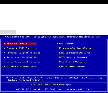
Main Page
Standard CMOS Features
Use this menu for basic system configurations, such as time, date etc.
Advanced BIOS Features
Use this menu to setup the items of AMI special enhanced features.
Advanced Chipset Features
Use this menu to change the values in the chipset registers and optimize your system performance.
Integrated Peripherals
Use this menu to specify your settings for integrated peripherals.
Power Management Setup
Use this menu to specify your settings for power management.
PNP/PCI Configurations
This entry appears if your system supports PnP/PCI.
H/W Monitor
This entry shows your PC health status.
12
Frequency/Voltage Control
Use this menu to specify your settings for frequency/voltage control.
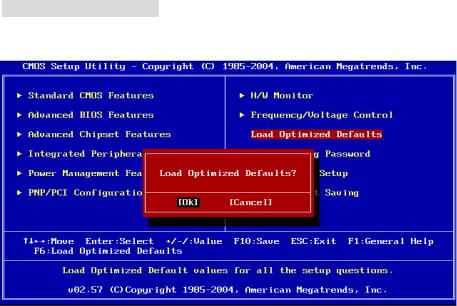
Load Optimized Defaults
Use this menu to load factory optimized default settings into the BIOS for stable system performance operations.
BIOS Setting Password
Use this menu to set Password.
Save & Exit Setup
Save changes to CMOS and exit setup.
Exit Without Saving
Abandon all changes and exit setup.
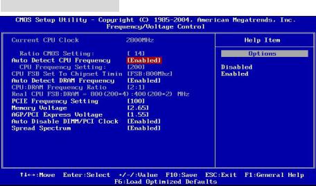
Frequency/Voltage Control
Auto Detect CPU Frequency
This item can auto detect the CPU frequency. When you set this item to “Disabled”, the following item “CPU Frequency Setting” will be selectable.
CPU Frequency Setting
This item allows you to select the CPU Front Side Bus clock frequency and overclock the processor by adjusting the FSB clock to a higher frequency. Select the number between [100]~[355] for needed frequency. The default settings are: [133], [200].
Auto Detect DRAM Frequency
This item can auto detect the DRAM frequency. When you set this item to “Disabled”, the following item “CPU:DRAM Frequency Ratio” will be selectable.
13
CPU:DRAM Frequency Ratio
This item allows you to select the CPU:DRAM frequency ratio. The setting options depend on CPU and DRAM frequencies.
Spread Spectrum
When the motherboard’s clock generator pulses, the extreme values (spikes) of the pulses creates EMI (Electromagnetic Interference). The Spread Spectrum function reduces the EMI generated by modulating the pulses so that the spikes of the pulses are reduced to flatter curves. If you do not have any EMI problem, leave the setting at [Disabled] for optimal system stability and performance. But if you are plagued by EMI, set to [Enabled] for EMI reduction. Remember to disable Spread Spectrum if you are overclocking because even a slight jitter can introduce a temporary boost in clock speed which may just cause your overclocked processor to lock up.
Load Optimized Defaults
You can load the BIOS Setup default values provided by the mainboard manufacturer for the stable performance.
For the complete BIOS introduction and setup, please visit MSI website at http://www.msi.com.tw
14

Introduction
Félicitations, vous venez d’acquérir une carte mère ATX 649 Neo-V (MS-7113 v1.X) Series. Les 649 Neo-V Series sont basées sur les chipsets SiS® 649 & SiS® 965L offrant un système très performant. La carte fonctionne avec les processeurs Intel® P4 Prescott 533/ 800MHz (LGA775), les 649 Neo-V Series est très performante et offre une solution adaptée tant aux professionnels qu’aux particuliers.
Schéma
T: mouse |
|
|
|
|
|
|
B: keyboard |
|
|
|
|
CPUFAN1 |
|
|
|
|
|
|
||
|
|
|
|
JPW1 |
|
|
|
|
|
|
|
|
ATX1 |
|
|
|
|
|
IDE2 |
IDE1 |
|
|
|
DIMM1 |
DIMM2 |
|
|
T:Line-In |
|
|
|
|
|
|
M:Line-Out |
|
|
|
|
|
|
B:Mic |
|
|
|
|
|
|
|
|
|
SiS |
|
|
|
|
|
|
649 |
|
|
|
|
|
|
Chipset |
|
|
|
|
|
|
PCI_E 1 |
|
|
|
Winbond |
|
|
|
|
|
|
W83627THF |
|
AGR Slot |
|
|
|
|
|
|
BATT |
|
|
|
|
|
|
+ |
PCI Slot 1 |
|
|
|
BIOS |
|
|
|
|
|
|
|
|
|
|
|
|
|
|
JBAT1 |
|
|
SiS |
SYSFAN1 |
|
|
|
PCI Slot 2 |
|
|
||
Codec |
|
965L |
|
|
||
|
|
|
|
|||
|
|
|
Chipset |
|
||
|
|
|
|
|
||
|
|
|
PCI Slot 3 |
|
SATA2 |
|
|
|
|
|
|
SATA1 |
|
|
|
|
|
|
|
|
JAUD1 |
CD1 |
|
JUSB1 JUSB2 |
JFP2 |
||
|
FDD1 |
|
JFP1 |
|
||
|
|
|
|
|
||
|
|
|
|
|
|
|
|
|
|
15 |
|
|
|

Spécificités
CPU
•Supporte les processeurs Intel Pentium 4 / Celeron D Prescott LGA775 pour LGA775
•Supporte jusqu’à Pentium 4 3XX, 5XX et 6XX ou plus.
•Supporte la technologie Intel Hyper-Threading.
(Pour les dernières mises à jours concernant les CPU, vous pouvez visiter : http://www.msi.com.tw/program/products/mainboard/mbd/pro_mbd_cpu_support.php.)
Chipset
•Chipset SiS® 649
-Supporte FSB 533/ 800 MHz.
-Supporte l’interface PCI Express x 16.
-Supporte la mémoire d’interface DDR333/ DDR400.
•Chipset SiS® 965L
-Contrôleur Hi-Speed USB (USB2.0), 480Mb/sec, 8 ports.
-2 ports Serial ATA avec taux de transfert jusqu’à 1.5Gb/s
-2 contrôleurs IDE Bus Master channel Ultra ATA 66/100.
-PCI Master v2.3, I/O APIC.
-Supporte à la fois l’ACPI et la gestion de l’alimentation (APM).
Mémoire Principale
•Supporte deux DIMM unbuffered DDR SDRAM
•Supporte jusqu’à 2GB de mémoire non ECC.
•Supporte DDR333/ DDR400 MHz.
(Pour connaître les derniers modules de mémoire supportés, vous pouvez visiter : http://www.msi.com.tw/program/products/mainboard/mbd/pro_mbd_trp_list.php)
Slots
•Un slot PCI Express x16 (Compatible avec les spécificités Bus PCI Express v1.0a).
•Un slot AGR (Advance Graphics Riser) compatible avec les cartes VGA AGP.
•Trois slots Bus PCI 2.3 32-bit (supporte l’interface bus PCI 3.3v/5v).
IDE Intégré
•Un contrôleur Ultra DMA 66/100/133 IDE intégré dans 965L.
-Supporte les modes opératoires PIO, Bus Master
-Possibilité de connecter jusqu’à quatre disques Ultra ATA.
•Contrôleur Serial ATA/150 intégré dans 965L
-Vitesse de transfert jusqu’à 150MB/sec.
-Possibilité de connecter jusqu’à deux disques Serial ATA.
16
Périphériques Intégrés
•Périphériques Intégrés Inclus:
-1 port floppy supportant 1 FDDs avec 360K, 720K, 1.2M, 1.44M et 2.88Mbytes.
-1 ports de série (Arrière * 1) et 1 port parallèle supportant les modes SPP/EPP/ECP.
-8 ports USB 2.0 (Arrière * 4/ Avant * 4).
-3 ports audio (Line-In/Line-Out/Mic).
-1 RJ-45 LAN Jack.
Audio
•Contrôleur AC97 link intégré dans chipset 965L.
•6 canaux audio codec ADI AD1888.
-Compatible avec les spec AC97 v2.3.
-Réponds aux exigences audio PC2001.
LAN
•Broadcom AC131
-Fast Ethernet PHY intégré.
-Supporte 10Mb/s et 100Mb/s.
-Compatible avec PCI 2.2.
-Supporte l’ACPI Power Management.
BIOS
•La carte procure un BIOS “Plug & Play” qui détecte automatiquement les cartes d’extension ou les périphériques.
•La carte offre une interface DMI (Desktop Management Interface) qui enregistre les spécificités de la carte mère.
Dimension
• Format ATX: 30.5 cm x 18.5 cm.
Montage
• 6 trous de montage.
Autres
•Supporte Clavier/Souris PS/2.
•Le « Hardware monitor » permet de surveiller la temperature & voltage.
17
Panneau Arrière
Le panneau arrière procure les connecteurs suivants:
Parallel port |
Line ln |
LAN |
|
Mouse |
|
|
USB ports |
|
|
|
|
|
|
|
|
|
|
|
|
|
|
|
|
|
|
|
|
|
|
|
|
|
|
|
|
|
|
|
|
|
|
|
|
|
|
|
|
|
|
|
|
|
|
|
|
|
|
|
|
|
|
|
|
|
|
|
|
|
|
|
|
|
|
|
|
|
|
|
|
|
|
|
|
|
|
|
|
|
|
|
|
|
|
|
|
|
|
|
|
|
|
|
|
|
|
|
|
|
|
|
|
|
Keyboard COM port |
|
|
|
|
|
|
|
|
USB ports Line Out |
|||||||||||
|
|
|
|
|
|
|
|
|
|
|
|
|
|
|
|
|
|
|
MIC |
|
Installation Matériel
Ce chapitre vous indique comment installer le processeur, barrettes de mémoire et cartes d’extension. Lors de l’installation des matériels, veuillez suivre les instructions de montage pour éviter d’endommager quoi que ce soit.
Central Processing Unit: CPU
La carte supporte les processeurs Intel Pentium 4 / Celeron D Prescott. Elle utilise le socket CPU LGA775. , Assurez-vous que vous possédez bien un ventilateur + dissipateur pour éviter la surchauffe. Si vous ne savez pas quel ventilateur utiliser, veuillez contacter votre revendeur avant de mettre en marche votre PC. (Pour une mise à jour sur les CPU, veuillez visiter http://www.msi.com.tw/program/products/mainboard/mbd/pro_mbd_cpu_support.php)
MSI Vous Rappelle...
Surchauffe
Une surchauffe endommagera sérieusement le CPU et le système. Soyez toujours sur du bon fonctionnement des ventilateurs et radiateurs pour protéger le CPU d’une surchauffe.
Overclocking
Cette carte mère a été créée pour supporter l’overclocking. Assurez vous que vos composants sont capables de tolérer de tels réglages, avant d’overclocker le système. Tout essais au delà des spécifications des produits n’est pas recommandé. Nous ne garantissons pas les dommages causés par une mauvaise opération ou au delà des spécifications du produit.
CPU LGA775 et installation Ventilateur (Le Clip CPU est optionnel)
Quand vous installerez votre CPU, assurez vous que le CPU possède un système de refroidissement pour prévenir les surchauffes. Si vous ne possédez pas de système de refroidissement, contactez votre revendeur pour vous en procurer un et installez le avant d’allumer l’ordinateur.
1.Le CPU possède un capuchon de protection pour éviter de l’endommager (à enlever avant installation). Effectuer une rotation du CPU pour aligner la broche n°1 (triangle jaune) avec le coin en bas à gauche du socket.
18
2.Prendre le CPU Clip bleu de MSI et le faire tourner afin qu’il s’aligne avec le socket.
3.Il faut ensuite retirer la protection qui se trouve sur le socket de la carte mère. Veuillez ne pas toucher aux broches du socket.
4.Aligner les indicateurs de couleur jaune (triangle sur le CPU & sur le
clip), et utiliser le clip MSI pour fixer le processeur sur le socket en pratiquant de la façon indiquée sur la photo.
5.Le CPU possède un capot plastique le protégeant. Ne jamais retirer le capot avant que le CPU ne soit installé.
6.Retirer la protection socket. Les broches du socket sont visibles.
7. Tirer le levier et ouvrir le plateau.
8.Aligner correctement les marques (clip + CPU).
9.Utilisez vos doigts pour assurer la connexion du CPU sur le socket.
10.Le CPU est bien installé sur le socket.
11.Regarder si le CPU est bien positionné dans le socket. Sinon, retirez le CPU et installez le de nouveau. Refermer le plateau.
12.Abaisser le levier, puis le sécuriser en l’attachant au mécanisme de rétention.
13.Aligner les trous de la carte mère avec le ventilateur. Appuyer sur le ventilateur jusqu’à ce que les clips soient dans les trous de la carte.
14.Appuyer sur les 4 parties (comme indiqué) puis effectuer une rotation (se référer aux marques) pour sécuriser.
15.Retourner la carte mère pour s’assurer que les clips sont bien insérés.
A Noter: Si vous désirez retirer le processeur, aligner les 4 points comme indiqué précédemment, et utiliser le clip pour retirer le CPU.
MSI Vous Rappelle...
1.Vérifier la connexion du ventilateur de CPU avant de démarre le PC.
2.Vérifier les informations dans le BIOS H/W Monitor au sujet de la température du CPU.
3.Ne pas toucher les broches du CPU pour éviter de les endommager.
4.Le CPU possède un capot plastique le protégeant. Ne jamais retirer le capot avant que le CPU ne soit installé pour éviter les dommages.
5.Attention, vous ne pouvez installer/retirer le CPU qu’un nombre de fois limitée à environ 20 cycles, par conséquent veuillez ne pas effectuer cette opération trop souvent.
Mémoire
La carte mère possède deux slots (184 broches) pour modules de mémoire DDR333 / DDR400 DDR SDRAM, et supporte un maximum de mémoire jusqu’à 2GB. Pour fonctionner correctement, il faut au moins installer un module de mémoire DIMM. (Pour les dernières mises à jours de mémoire supportées, merci de visiter http://www.msi.com.tw/program/products/mainboard/mbd/pro_mbd_trp_list.php)
Installer au moins un module DIMM sur les slots. L’installation des modules de mémoires n’a pas de sens particulier. Vous pouvez installer soit des modules simples ou doubles faces selon vos besoins.
19
Volt Notch
1.Le DDR DIMM ne possède qu’une encoche en son centre. Ainsi il n’est possible de monter le module que dans un seul sens.
2.Insérez le module de mémoire DIMM verticalement dans le slot. Puis appuyez dessus
3.Le clip en plastique situé de chaque côté du module va se fermer automatiquement.
Alimentation
La carte mère supporte les alimentations ATX. Avant de brancher le connecteur d’alimentation, Il faut toujours vous assurer que tous les composants sont bien installés afin de ne pas les endommager. Une alimentation 300W ou supérieur est préconisée.
Connecteur d’Alimentation ATX 24 Broches : ATX1
Ce connecteur vous permet de connecter l’alimentation ATX. Pour ce faire assurez-vous que le connecteur est bien positionné dans le bon sens. Puis appuyer sur le câble.
Vous pouvez aussi utiliser une alimentation 20 broches, le détrompeur permettra de ne pas connecter l’alimentation sur les broches 11, 12, 23 & 24.
+3.3V -12V GND PS-ON# GND GND GND Res +5V +5V +5V GND
13 |
1 |
|
+3.3V |
|
+3.3V |
|
GND |
|
+5V |
|
GND |
|
+5V |
|
GND |
|
PWR OK |
|
5VSB |
|
+12V |
|
+12V |
|
NC |
24 |
12 |
Connecteur d’Alimentation ATX 12V: JPW1
Le connecteur d’alimentation 12V est utilisé pour alimenter le CPU
Connecteur Floppy Disk Drive: FDD1
4 |
2 |
12V |
GND |
12V |
GND |
3 |
1 |
La carte offre un connecteur standard floppy disk drive (lecteur de disquette) qui supporte les disques 360K, 720K, 1.2M, 1.44M et 2.88M.
Connecteurs IDE: IDE1/ IDE2
La carte mère possède un contrôleur 32-bit Enhanced PCI IDE et Ultra DMA 66/100/133 qui procure les fonctions PIO mode 0~4, Bus Master, et Ultra DMA 33/66/100/133. Vous pouvez connecter jusqu’à 4 matériels (disques durs, CD-ROM, 120MB Floppy).
Le premier disque dur doit être connecté sur l’IDE1. L’IDE1 peut recevoir un matériel Maître et un Esclave. Vous devez configurer le second disque en mode Esclave et ce à l’aide du cavalier situé à l’arrière
20
 Loading...