MSD 8961 Installation

MSD RELAYS
PN 8961, Single-Pole, Double-Throw, 30 Amp/12 VDC PN 8960, Double-Pole, Double-Throw, 30 Amp/12 VDC
MSD Relays will allow you to activate a variety of accessories that require high current. These are ideal to tie in with an rpm activated switch to control a nitrous or air shifter solenoid.
The benefit of a relay is that it can be energized using a small amount of power (12V/1 Amp). This moves the relay's armature so it can transfer a large amount of power (12V/30 Amp) to activate a high current device.
•The PN 8960 will handle a 30 Amp load, on each side, with an input voltage of 12 volts.
•The PN 8961 Relay will handle a 30 Amp load and is ideal for multiple accessories.
Following is a short description of the operation of a relay. A variety of wiring schematics are also included to help with your installation.
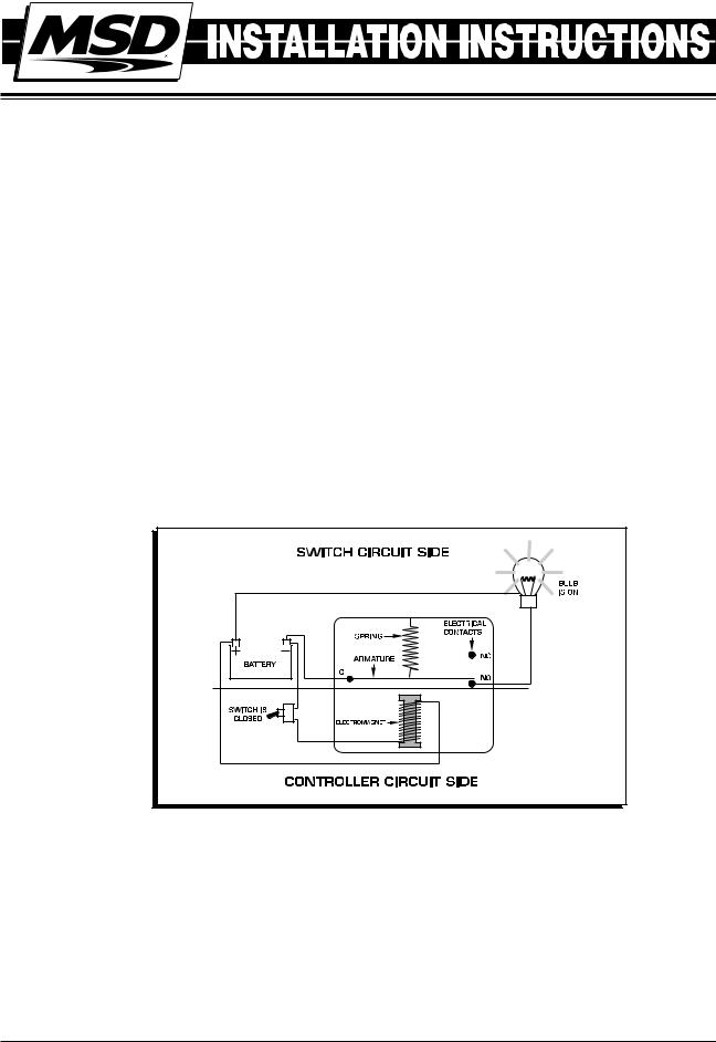
Relays are very simple devices and consist of four basic parts:
•A small coil (sometimes referred to as a bobbin or electromagnet)
•An armature
•A spring
•A set of electrical contacts
Figure 1 General Relay.
Relays consist of two separate and completely independent circuits; the Controller circuit and Switch circuit. In Figure 1 the Controller circuit is on the bottom and it controls the power to the electromagnet. When 12 volts are supplied through the switch, the coil is energized. When energized, it attracts the armature of the Switch circut.
The Switch circuit consists of an armature, spring and contacts for the high current side. The armature is a switch and will complete or open the high current circuit. When the coil of the relay is energized, it attracts the armature from one electrical contact to another to complete the circuit. When the coil is not energized the spring pulls (or pushes) the armature back and the high current circuit is opened.
M S D • W W W . M S D P E R F O R M A N C E . C O M • ( 9 1 5 ) 8 5 7 - 5 2 0 0 • F A X ( 9 1 5 ) 8 5 7 - 3 3 4 4

2 |
INSTALLATION INSTRUCTIONS |
|
|
Relays have a variety of specifications. A few things to consider include:
•Make sure the Relay can accept and handle the voltage and current required to activate the desired circuit.
•The number of bobbins to use with different circuits (generally 1-2).
•The number of electrical contacts for the armature (generally 1-2).
•If the Relay is Normally Open (NO) or Normally Closed (NC).
RELAY APPLICATIONS
Here are some examples of how a Relay can be used in typical automotive applications.
|
|
|
|
MSD PN 8961 RELAY |
|
|
||
|
|
INSIDE |
|
LOCATION OF PINS |
||||
NO - NORMALLY OPEN |
86 |
|
87 |
87A |
|
87 NO |
|
|
NC - NORMALLY CLOSED |
|
|
|
|
||||
|
|
|
|
|
|
|
||
C - COMMON |
|
|
|
|
|
|
|
|
|
|
|
|
|
|
87A NC |
|
85 |
|
|
|
|
|
|
86 |
|
|
|
|
|
|
|
|
30 C |
|
|
|
85 |
|
30 |
|
|
|
|
|
|
|
|
|
MSD PN 8960 RELAY |
|
|
||
|
1 |
7 |
8 |
6 |
1 |
7 |
8 |
6 |
|
|
|
|
|
|
NC |
C |
NO |
|
0 |
3 |
4 |
2 |
0 |
3 |
4 |
2 |
Figure 2 Inside the MSD Relays.
USING MSD RPM ACTIVATED SWITCH, PN 8950, AND
MSD RELAY, PN 8961, TO ACTIVATE A SOLENOID
RED
12 VOLTS
NITROUS OR
AIR SHIFT
SOLENOID
TO
GROUND 
|
RELAY |
|
RED |
|
PN 8961 |
|
|
||
|
|
|
|
YELLOW COMPLETES THE |
|
30 |
|
|
GROUND PATH OF THE CIRCUIT |
85 |
86 |
YELLOW |
|
|
|
87a |
|
R |
|
|
|
|
|
|
RPM
87 

 ACTIVATED
  SWITCH

WHITE TO |
GRAY |
PN 8950 |
1490 HENRY BRENNAN DR., EL PASO, TX. 79936 |
||
|
|
AUTOTRONIC CONTROLS CORPORATION |
MSD TACH |
(NOT USED) |
BLACK |
TERMINAL |
|
TO |
OR COIL (-) |
|
GROUND |
Figure 3 Connecting a Transmission Solenoid with an MSD RPM Activated Switch and PN 8961 Relay.
M S D • W W W . M S D P E R F O R M A N C E . C O M • ( 9 1 5 ) 8 5 7 - 5 2 0 0 • F A X ( 9 1 5 ) 8 5 7 - 3 3 4 4
 Loading...