


Soft Touch Rev Control
PN 8728
ONLINE PRODUCT REGISTRATION: Register your MSD product online and you’ll be entered in our monthly 8.5mm Super Conductor Spark Plug Wire give-away! Registering your product will help if there is ever a warranty issue with your product and helps the MSD R&D team create new products that you ask for! Go to www.msdperformance.com/registration.
Note: This Soft Touch Rev Control, PN 8728, is designed for inductive style ignition systems only. It cannot be used with an MSD Ignition Control!
|
Parts Included: |
4 |
- Wire Splicers |
|
|
|
|
||||
|
1 |
- Soft Touch Rev Control |
|
||
|
4 |
- Mounting Pads and Sleeves |
4 |
- Self Tapping Screws |
|
|
4 - RPM Modules, 3,000, 6,000, 7,000, 8,000 |
4 |
- Wire Insulating Caps |
|
|
|
|
|
|
|
|
WARNING: During installation, disconnect the battery cables. When disconnecting the battery, always remove he Negative cable first and install it last.
Note: The RPM limit is set with plug-in rpm modules. If an rpm module is not installed, there will be no rpm limit.
CYLINDER SELECT
The Soft Touch Rev Control comes from MSD programmed for 8-cylinder applications. It can easily be adjusted for operation on other engines by cutting the cylinder select wire loops (Figure 1). If the loops are cut, use the supplied insulating caps to seal the wire ends.
MOUNTING
Figure 1 Selecting the Number of Cylinders.
The Rev Control can be mounted in the engine
compartment but away from direct heat sources. It is recommended to mount it where the rpm module is easy to access for rpm adjustments. Make sure all of the wiring reaches their connections. Once a suitable mounting location is determined mark the location of the mounting holes by using the unit as a template. Remove the unit and use an 1/8” bit to drill the holes. Install the supplied mounts and use the four self tapping screws to secure the Control (Figure 2).
Figure 2 Installing the Vibration Mounts.
M S D • W W W . M S D P E R F O R M A N C E . C O M • ( 9 1 5 ) 8 5 7 - 5 2 0 0 • F A X ( 9 1 5 ) 8 5 7 - 3 3 4 4
2 |
INSTALLATION INSTRUCTIONS |
|
|
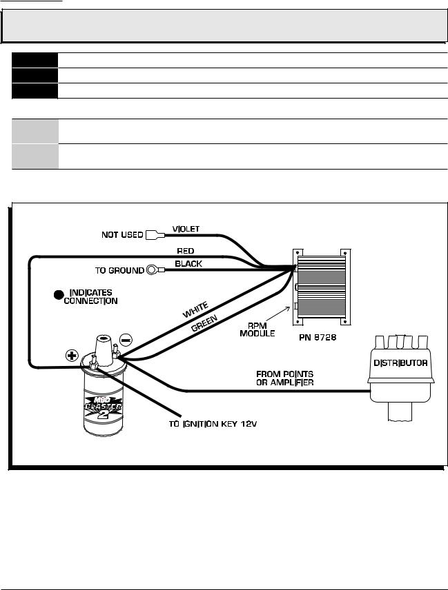
WIRING
WARNING: High voltage is present on the coil terminals. Do Not touch the coil terminals or tower when the engine is cranking or running.
Red Connects to a switched 12 volt source.
Black Connects to ground on the engine.
Green Connects to the coil negative (-) terminal.
Trigger Pickup Wires
White If the distributor is triggered by breaker points or an amplifier, this wire needs to be spliced to its trigger wire.
Violet If the distributor uses a magnetic pickup, this wire needs to be spliced into the positive mag pickup wire.
Figure 3 Wiring to a Points/Amplifier Ignition.
M S D • W W W . M S D P E R F O R M A N C E . C O M • ( 9 1 5 ) 8 5 7 - 5 2 0 0 • F A X ( 9 1 5 ) 8 5 7 - 3 3 4 4

INSTALLATION INSTRUCTIONS |
3 |
|
|
Note: The GM Unitized Coil, HEI Distributor was produced with several different modules. If this installation seems to cause a rough limit, try the wiring shown in Figure 5 below.
Figure 4 Wiring to a GM HEI Distributor, using the Module.
Figure 5 Wiring to a GM HEI Distributor using the Magnetic Pickup. |
M S D • W W W . M S D P E R F O R M A N C E . C O M • ( 9 1 5 ) 8 5 7 - 5 2 0 0 • F A X ( 9 1 5 ) 8 5 7 - 3 3 4 4 |
 Loading...