


Atomic EFI
PN 2910 - Throttle Body Kit
ONLINE PRODUCT REGISTRATION: Register your MSD product online. Registering your product will help if there is ever a warranty issue with your product and helps the MSD R&D team create new products that you ask for! Go to www.msdperformance.com/registration.
Thank you for selecting the Atomic TBI Fuel Injection System! MSD’s Atomic EFI systems were designed with two major goals; to simplify EFI and deliver better overall performance to your engine. Simplicity is achieved through with less wiring to ease installation plus programming is simple with no PC required! Performance is delivered through advanced control of the fuel and ignition, just as you’d expect from MSD.
As with any performance product, please be sure to read the entire instruction manual before attempting to install this system on your vehicle. Please contact our Customer Support department if you have any questions about your Atomic installation at (915) 855-7123. There are also some helpful installation videos available at www.atomicefi.com.
|
Parts Included: |
1 |
- O2 |
Sensor |
4 ft. CAN Extension |
|
|
|
|
||||||
|
1 |
- Throttle Body w/ECU |
|
||||
|
1 |
- TB Harness |
1 |
- O2 |
Bung and Plug |
Air Filter Gasket |
|
|
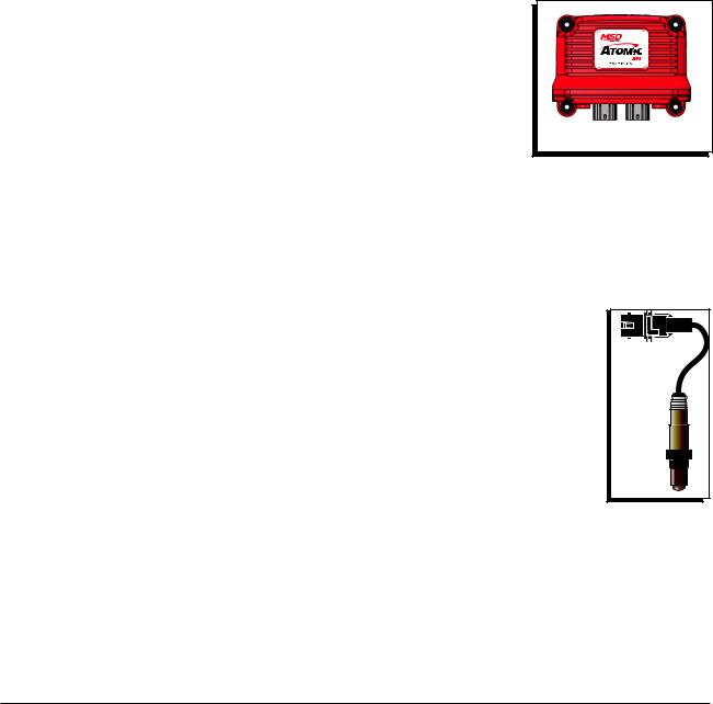
1 |
- Power Module |
4 |
- Rubber Grommet |
Intake Manifold Gasket |
|
|
|
1 |
- PM Harness - w/ WBO2 |
4 |
- Eyelet Insert |
1 - Fitting 6AN Adapter 6 Male |
|
|
|
1 |
- Handheld Monitor |
4 |
- Mounting Screws |
|
|
|
|
1 |
- Coolant Temp Sensor |
1 |
- 4G Micro SD Card |
|
|
|
|
|
|
|
|
|
|
|
|
|
|
|
|
|
|
|
Not legal for use on pollution controlled vehicles: The MSD Atomic EFI system is not CARB approved for use on emission controlled vehicles.
WARNING Installation of this product requires detailed knowledge of automotive systems  and repair procedures. Installation of fuel system parts and any fuel tank modifications must be carried out by a qualified automotive technician. Installation of fuel system parts requires handling of gasoline. Ensure that work is performed in a well ventilated area with an approved fire extinguisher nearby. Extinguish all open flames, prohibit smoking and eliminate all
sources of ignition in the area of the vehicle before beginning the installation.
When working with fuel systems, eye goggles and other safety apparel should be worn to protect against debris and sprayed gasoline. The finished work must be thoroughly checked to ensure there are no fuel leaks.
CONTENTS:
Parts Review and System Capabilities. . . 2
Fuel System Overview and Requirements. . 3
02 Sensor Installation. . . . . |
. . |
. . |
. 5 |
Throttle Body Installation . . . |
. . |
. . . |
6 |
Power Module Installation and Wiring . . . 9 |
|||
Throttle Body Wiring. . . . . |
. . |
. 7, 10-11 |
|
System Wiring.. . . . . . . |
. . . . 9-11 |
||
Wiring with Timing Control. . |
. . . 16-18 |
||
Programming |
|
|
|
|
Initial . . . . . . . . . . . . . . |
. |
12 |
|
Advanced . . . . . . . . . . . . . 13 |
||
Final Adjustments. . . . . . . . . . |
. |
15 |
|
Diagnostics. . . . . . . . . . . . . |
|
20 |
|
M S D • W W W . A T O M I C E F I . C O M • (915) 855 - 7123 • FAX (915) 857 - 3344
2 |
INSTALLATION INSTRUCTIONS |
|
|
CAPABILITIES
The Atomic TBI is designed to install on a standard square bore intake manifold flange. It is a selftuning EFI system that continuously adjusts after the basic configuration is complete. There is no laptop programming. Base on the engine descriptors that you input during the initial setup, the Atomic will automatically create a base fuel map to get the engine running. Once the system is started the self learning technology will optimize those maps resulting in the best performance possible. If you drive through altitude changes, temperature swings or other factors the Atomic will adjust accordingly, on the fly. This ensures that your engine will produce excellent driveability at all times, even from the sunny coast to the cool mountains.
There three main components of the Atomic TBI; the throttle body, the Power Module and the Handheld Monitor. The ECU of the system is built into the passenger side of the throttle body and there are several sensors integral to the unit including the Throttle Position Sensor (TPS), Manifold Absolute Pressure (MAP), Intake Air Temperature (IAT) and the Fuel Pressure Sensor.
Power Module: The Power Module of the Atomic LS is the communication hub of the system and provides the high current fuel pump circuit and other input/outputs for optional features. The unit has two ports for the MSD CAN system as well as a wiring harness. There are connections for the WB02, the Handheld Monitor as well as power and communication to the integrated fuel rails.
Programming: To program the Atomic for your specific engine application,
there no need (or method) to connect a PC to the system. All of the programming is performed through a simple to use Handheld
Monitor. The Monitor simply plugs into the Power Module. Once the few initial setup selections are answered and the engine is running the Monitor can be removed or left connected. When it is connected, there is a Dash and Gauges screen that show engine parameters in real time.
Fuel System: The Atomic TBI system can be used with return or returnless EFI system. Review the Fuel System Information section starting on page 3 for detailed information.
Wide-Band 02 Sensor: A Wide-Band 02 sensor is supplied in the Atomic TBI Kit. This sensor is responsible for constantly monitoring the exhaust gases and relaying that information to the ECU where adjustments are continually made to the fuel delivery in order to meet the air/fuel targets. Only one sensor is required. Page 5 outlines sensor installation.
Trigger Signal: The Atomic TBI requires an rpm/trigger reference signal to operate. This signal be a 12-volt square wave reference signal from the tach output of an MSD ignition control or it can be achieved when connected to coil negative with breaker points, GM HEI or Ford TFI inductive based ignition system.
O2 |
SENSOR |
Timing Control: The Atomic TBI is capable of controlling the ignition timing. To use
this function an MSD 6A or other ignition control must be installed. The distributor must also be locked-out. There are settings for Idle timing, Total advance and Vacuum advance through the handheld monitor. Pages 16-19 explain the timing control setup in detail.
Rev Limiter: A fuel controlled rev limiter can be set through the Atomic. When the engine rpm reaches the programmed value, fuel will be cut off to achieve the desired limit. Any ignition related rpm limit is set and acts independently of the Atomic.
M S D • W W W . M S D P E R F O R M A N C E . C O M • (915) 855-7123 • FAX (915) 857-3344

INSTALLATION INSTRUCTIONS |
3 |
|
|
Power Adders: The Atomic TBI can operate in conjunction with wet nitrous systems as well as positive manifold pressure supplied by a draw-thru or blow-thru forced induction system. For nitrous, there is a program that allows you to set a target air/fuel ratio when the nitrous is activated as well as a selection to retard the timing (when timing control is incorporated) Note that a wet nitrous system requires its own fuel pump to supply the additional fuel required with nitrous.
For forced induction applications there is a target air/fuel ratio setting which takes effect when operating under boost. These options are explained in the Advanced Settings section, page 13.
FUEL SYSTEM REQUIREMENTS
The following details pertain to the fuel system requirements. Installation steps specific to the fuel system are covered in the Fuel Pump Kits supplied separately from the Atomic TBI, PN 2910, Kit. The Atomic TBI requires a high pressure fuel pump system. Depending on your engine combination, the Atomic TBI requires a minimum of 42-48 psi to operate and it can be used with a return or returnless fuel system. When selecting a pump, regulator and lines, be sure each component is designed to perform at high pressure. MSD offers a fuel pump, hose and accessories to complete your installation. Following are some guidelines in helping set up a fuel system for your Atomic as well as components available separately from MSD.
•The Atomic is capable of operating with a return or returnless style system. For best results, MSD strongly recommends an in-tank pump. Installing the fuel pump in the tank results in quieter operation, less chance of cavitation and a reduction in pump temperature.
•When running a returnless fuel system (Pulse Width Modulated), it is strongly recommended to install the pump in the tank. It is recommended to use an MSD Atomic Fuel Pump, PN 2925 or PN 2926.
•If mounting the pump in the tank is not an option, install the pump as close as possible to the tank.
Within 2-feet of sending unit is recommended.
•Do NOT use hard line when plumbing the fuel system. When using a PWM fuel system, cavitation could cause unstable fuel pressure resulting in poor engine performance.
•When used, an adjustable regulator must be installed on the return side of the throttle body.
FUEL SYSTEM EXAMPLE
FUEL
FILTER
MSD ADJUSTABLE
REGULATOR
IT IS RECOMMENDED TO MOUNT THE FUEL PUMP IN THE TANK WHENEVER POSSIBLE. IF IT MUST BE MOUNTED EXTERNALLY, MOUNT THE PUMP WITHIN 2-FEET OF THE FUEL TANK SENDING UNIT.
FUEL TANK
FUEL
PUMP
NOTE: IF RUNNING A RETURNLESS SYSTEM, THE PUMP MUST
MOUNTED IN THE TANK.
NOTE: DO NOT USE TUBING (HARDETURNFUELINELINES) WITH THE ATOMIC EFI SYSTEM.
Figure 1 Atomic Return Style Fuel System.
WARNING: MSD’s Push-Lock fittings are designed for use with the MSD fuel hose only. Do not use the MSD fuel hose with other fittings. Do not use MSD Push-Lock fittings with other fuel hose. Compatibility issues may cause fuel leaks.
M S D • W W W . A T O M I C E F I . C O M • (915) 855 - 7123 • FAX (915) 857 - 3344

4 |
INSTALLATION INSTRUCTIONS |
IN-TANK PUMPS
The MSD Atomic Fuel Pump (supplied only with Master Kit PN 2900) can be used in the tank however it would require a sock, or filter element, on the pickup side (Figure 1). It is important to note that the wiring used to run the pump will need to meet requirements to be submersed in fuel. When wiring an in-tank pump, it is recommended to use a wire that conforms to SAE specifications J1128 and J378. This wiring features a thermoplastic insulated wiring with polyvinyl chloride insulation for protection against gasoline, oil, and more.
In addition, different fuel line will be required internally if the pump is to be mounted in the tank. Fuel line that meets SAE 30R10 specifications MUST be used. Failure to do so will cause severe damage to your engine and/or fuel system.
WARNING: Improper installation or use of fuel system components can cause severe damage your engine and/or fuel system that will not be covered by the manufacturer’s warranty.
Atomic Fuel Pump, PN 2925: This pump features 3/8” inlet and outlet and is rated at 70 psi. The pump will support approximately 525 hp and is approved for in-tank use (no wiring or in-tank mounting hardware/ pickup element are supplied).
Fuel Pump Kit, PN 2920: This Kit is supplied with MSD’s PWM Fuel Pump, a preand post-filter, 15-ft of 3/8 fuel injection line and mounting hardware.
Fuel System Return Kit, PN 2922: If you plan on running a return line with your Atomic LS, this kit provides another 15-ft of 3/8” injection line, an MSD Regulator and two push-lock fittings.
High Horsepower Fuel Kit, PN 2921:This pump will support the power demands of engines up to 650 horsepower. The pump features 3/8” inlet and outlet and is rated at 70 psi. The pump will support approximately 650 hp and is approved for in-tank use (no wiring or in-tank mounting hardware/sock are supplied).
POWER ADDERS
The Atomic TBI will accept wet nitrous systems as well as forced induction systems generating up to 10-14 psi of manifold pressure. There are options to select in the Advanced settings that allow you to program an air/fuel target when the nitrous is activated and when under boost conditions.
Nitrous: The Atomic fuel system does not provide the extra fuel required to safely operate a wet nitrous system. The installation of a dedicated fuel pump for the nitrous system is required in order to meet the fuel demands of a wet nitrous system. Timing can also be pulled out when the nitrous is activated (only when timing is being controlled by the Atomic system.)
Forced Induction: In boosted applications, the fuel pump must be capable of meeting the requirements of the increased fuel demand. Due to injector flow limitations, max horsepower with forced induction systems will be limited to 525 horsepower. Proper fuel pump selection is imperative to the performance and operation of the Atomic EFI.
WIDE BAND OXYGEN SENSOR INSTALLATION
The MSD Atomic EFI system requires a single Wide Band |
02 SENSOR |
|
Oxygen Sensor (WBO2) for operation. MSD suggests that |
||
the bung for this sensor be installed prior to starting any |
|
|
other part of the conversion process. By having the WBO2 |
|
|
in place first, there is a reduced chance of the vehicle being |
POSITION |
|
immobilized for an extended time. The bung for the WBO2 |
||
AT LEAST |
||
provided by MSD has a plug included so that the vehicle |
||
10° |
||
can be driven between the time of exhaust modification and |
||
|
||
installing the rest of the Atomic system, if needed. |
|
|
|
EXHAUST |
|
|
COLLECTOR |
|
|
Figure 2 WBO2 Sensor Location. |
M S D • W W W . M S D P E R F O R M A N C E . C O M • (915) 855-7123 • FAX (915) 857-3344

INSTALLATION INSTRUCTIONS |
5 |
|
|
The WBO2 can be installed downstream of either exhaust bank. The sensor connects to the Power Module, so install the sensor on the bank closest to where you plan to mount the Module. The bung should be installed by a qualified exhaust technician and pressure tested. Proper installation of the oxygen sensor is critical to the performance of the Atomic EFI. Improper installation could lead to engine damage.
1.Locate the ideal spot to install the WBO2.
a.This location should be 2-4 inches after the exhaust collector. The sensor must be more than 18 inches forward of the exhaust tip. For applications where short or open headers are used, install the WBO2 in the primary tube of the rear cylinder at least 8 inches away from the exhaust port. The Atomic will not work on “Zoomie” style headers.
b.The WBO2 sensor should be at least 10˚ above horizontal to allow condensation runoff. Without this angle the sensor is significantly more likely to sustain water damage (Figure 2).
c.Never place a WBO2 on the outside of a bend.
d.The WBO2 must be mounted in the exhaust prior to any catalytic converter, if applicable.
2.Drill a 7/8” hole in the exhaust where the WBO2 will go.
3.Weld in the supplied bung. Ensure the weld goes completely around the bung and is air tight.
4.Insert supplied plug in bung. Never run the vehicle with a WBO2 installed but not powered; it will damage the sensor.
5.When completing the Atomic EFI installation, remove the plug and insert the WBO2 for use. MSD suggests using a small amount of anti-seize on the threads.
Note: The Atomic EFI is extremely sensitive to air leaks in the exhaust system. Any air leak between the engine and the WBO2 will cause the Atomic to have false readings, which can lead to poor engine performance, misfires, and an inability to properly auto-tune. Extended running of the Atomic EFI with an exhaust leak can result in detonation and severe engine damage. Improper installation of the oxygen sensor, and any damage that may result from such an installation, is not covered by the manufacturer’s warranty.
THROTTLE BODY
Parts Required, not included:
4 – Retaining Stud Kit for the throttle body Throttle linkage connection/brackets
The Atomic Throttle Body will bolt in place on intake manifolds designed for a square bore style carburetor. It is designed to accept common throttle linkage adapters and brackets. A throttle ball stud is supplied but no other linkage components are included. Accessory kits are available through many accessory or carburetor companies.
There are two fuel inlets, a forward and rear fuel inlet. Only one needs to be connected on a PWM (returnless) style system as fuel is delivered to either side through an internal fuel rail. The passenger side of throttle body, where the MSD is machined, is the Electronic Control Unit (ECU). This is the brains of the Atomic fuel system and where all of the fuel calculations are made to give your vehicle exceptional performance.
VACUUM PORTS
MANIFOLD PORTED
BOOST
REFERENCE
PORT MANIFOLD
Figure 3 Vacuum Ports.
Before installing the throttle body, note the engine’s need for vacuum accessories. The Atomic has five vacuum ports, ported and manifold, to cover accessories such as a power brake booster (Figure 3). Four ports are 1/8" NPT and one is 1/4" NPT.
M S D • W W W . A T O M I C E F I . C O M • (915) 855 - 7123 • FAX (915) 857 - 3344

6 |
INSTALLATION INSTRUCTIONS |
BOOST REFERENCE PORT
Blow-Thru applications do not require modifications to the boost reference port. Draw-thru applications require a few modifications to the throttle body. Locate the boost reference port on the throttle body. It is located on the lower right corner of the throttle body on the same side as the IAC motor (back of the throttle body), and remove the plug. Turn the throttle body upside down. Using a small drop of Loctite on the plug, install the plug into the threaded orifice next to the throttle blades. Install A 1/16 pipe to hose fitting into the boost reference port on the throttle body. The boost reference port on the throttle body should be referenced below the supercharger directly off of the manifold, or can be split off of the boost gauge reference line (Figure 4).
PLUG PORT |
|
BOOST REFERENCE PORT AND PLUG |
|
OR |
VACUUM HOSE |
|
TO ATOMIC EFI |
TO MANIFOLD |
|
Figure 4 Boost Reference Port.
INSTALLATION
1.Install the new gasket and place the throttle body on the intake manifold. Make sure the throttle body is square on the intake and the linkage moves through closed throttle to wide open.
2.Secure the throttle body by tightening the four retainers evenly. Do not over tighten.
3.Transfer the linkage hardware from the carburetor to the Atomic. Any transmission brackets should also be transferred to the Atomic. A throttle return spring must be used (Figure 5).
4.Install the new air horn gasket.
5.Determine which fuel inlet and AN-fitting best suits your application.
6.MSD supplies two -6 AN style fittings for use on the Figure 5 Throttle Linkage.
throttle body fuel inlet. Both use ‘push-lock’ style inlets
to connect to the fuel hose and do not require clamps. Page 8 details the installation of MSD's pushlock fittings and hose.
Note: Not all fuel lines are rated for "push lock" installation. 7. Install the fitting to the throttle body.
M S D • W W W . M S D P E R F O R M A N C E . C O M • (915) 855-7123 • FAX (915) 857-3344

INSTALLATION INSTRUCTIONS |
7 |
|
|
EXTERNAL SENSORS
There are only two external sensors that need to be installed and connected; the Wide Band Oxygen Sensor and the Engine Coolant Temperature Sensor. (Both are supplied.) The Wide Band Oxygen Sensor installation is covered on page 5.
The coolant sensor is a variable resistance sensor and needs to be installed in the engine.
1.Find a location for the coolant temperature sensor. Many engines have provisions on the cylinder heads or the intake manifold.
2.It is recommended to use a small amount of Teflon tape or sealer on the threads.
3.Locate the 2-pin coolant sensor wiring harness. Route and connect the harness to the coolant temperature sensor.
WIRING
There are several wires and connectors on the throttle body. Not all of these wires will be connected on every application. Following is a chart of each wire.
REQ. / OPT. |
Wire Color |
Description |
|
|
|
REQ |
Yellow |
This connects to the Engine Coolant Temperature Sensor. |
|
Black |
|
|
|
|
REQ |
White |
This is the tach input wire for the EFI responsible for triggering the system. |
|
|
It connects to the tach output of an MSD Ignition Control or Ready-to-Run |
|
|
Distributor. It can also be connected to the coil negative terminal when |
|
|
using a stock type ignition such as points or a GM HEI distributor. Note: |
|
|
This wire is not used when the magnetic pickup wire is being used |
|
|
for ignition timing. |
|
|
|
OPTIONAL |
Yellow |
This is a tach output wire. Connect this wire to the White points input |
used with |
|
wire on an MSD ignition unit only when using the Atomic to control |
timing |
|
timing. If the Atomic is not controlling timing this wire can be used as |
control |
|
a 12 volt square wave trigger to a tachometer. |
|
|
|
OPTIONAL |
Orange |
This is an AC kick-up wire. When 12 volts are supplied to this wire |
used with |
|
it will provide a small rpm "kick-up" in the idle to compesate for an |
A/C |
|
added load to the engine from the air conditioner compressor. It will |
|
|
also activate the primary cooling fan (when two are used). |
|
|
|
OPTIONAL |
Violet (+) |
This is the input for a magnetic pickup, such as from an MSD distributor. |
used with |
Green (–) |
This connector is only used when the Atomic is controlling ignition |
timing |
|
timing. |
control |
|
|
REQ |
CAN-Bus |
The 6-pin connector must connect to the Power Module. Do NOT |
|
|
cut this harness. MSD offers extensions in 2, 4 and 6-feet lengths if |
|
|
needed. |
|
|
|
M S D • W W W . A T O M I C E F I . C O M • (915) 855 - 7123 • FAX (915) 857 - 3344

8 INSTALLATION INSTRUCTIONS
PUSH-LOCK FITTING INSTALLATION |
|
CORRECT CLEAN, |
|
|
||||||||||||
|
|
|
||||||||||||||
MSD supplies two fitting adapters that will accept a |
|
SQUARE CUT |
|
|
||||||||||||
-6 AN line to be connected. If you are using the MSD |
|
|
|
|
|
|
|
|
|
|
|
|
|
|
|
|
Push-Lock fittings to connect the fuel hose, the supplied |
|
|
|
|
|
|
|
|
|
|
|
|
|
|
|
|
hose MUST be used. |
|
INCORRECT |
|
|
||||||||||||
|
|
|
|
|||||||||||||
Proper installation begins with a clean, square cut of |
|
JAGGED, ROUGH |
|
|
||||||||||||
|
CUT RESULTS IN |
|
|
|||||||||||||
the hose. A hose cutting tool or new razor blade are |
|
|
|
|||||||||||||
|
A COMPROMISED |
|
|
|||||||||||||
recommended. When installing the hose it is important |
|
CONNECTION |
|
|
||||||||||||
that the hose is pushed on all the way to the thin beauty |
|
|
|
|
|
|
|
|
|
|
|
|
|
|
|
|
ring. This means the hose should fully overlap the |
|
|
|
|
|
|
|
|
|
|
|
|
|
|
|
|
|
|
|
|
|
|
|
|
|
|
|
|
|
|
|
|
|
inboard barb. Too little of engagement, as well as over- |
|
Figure 5 Severing the Hose Properly. |
|
|
|
|||||||||||
engagement, will result in a compromised connection that |
|
|
|
|
|
|
|
|
|
|
|
|
|
|
|
|
|
|
|
|
|
|
|
|
|
|
|
|
|
|
|
|
|
|
|
|
|
|
|
|
|
|
|
|
|
|
|
|
|
|
is prone to failure. Figures 6 and 7 illustrate the required |
|
|
|
|
|
|
|
|
|
|
|
|
|
|
|
|
installation of the hose and fittings. |
|
|
|
|
|
|
|
|
|
|
|
|
|
|
|
|
1. Determine the length of hose needed. Mark the hose |
|
|
|
|
|
|
|
|
|
|
|
|
|
|
|
|
|
|
|
|
|
|
|
|
|
|
|
|
|
|
|
|
|
|
|
|
|
|
|
|
|
|
|
|
|
|
|
|
|
|
and cut it using a hose cutter or new razor blade. |
|
|
|
|
|
|
|
|
|
|
|
|
|
|
|
|
There should be minimal disturbance of the outer |
|
|
|
|
|
|
|
|
|
|
|
|
|
|
|
|
|
|
|
|
|
|
|
|
|
|
|
|
|
|
|
|
|
jacket, braids and inner liner. The cut plane should |
|
|
|
|
|
|
|
|
|
|
|
|
|
|
|
|
be perpendicular to the hose axis. (Figure 5). |
|
|
|
|
|
|
|
|
|
|
|
|
|
|
|
|
|
|
|
|
|
|
|
|
|
|
|
|
|
|
|
|
|
2. Before installing the hose to the fitting, it is important to |
|
|
|
|
|
|
|
|
|
|
|
|
|
|
|
|
|
|
|
|
|
|
|
|
|
|
|
|
|
|
|
|
|
anchor the fitting (Figure 6). Proper installation cannot |
|
|
|
|
|
|
|
|
|
|
|
|
|
|
|
|
be achieved by holding the hose and fitting in your |
|
|
|
|
|
|
|
|
|
|
|
|
|
|
|
|
|
|
|
|
|
|
|
|
|
|
|
|
|
|
|
|
|
hands. For best results, the hose should be installed |
|
|
|
|
|
|
|
|
|
|
|
|
|
|
|
|
with minimal twisting or pausing. |
|
|
|
|
|
|
|
|
|
|
|
|
|
|
|
|
|
|
|
|
|
|
|
|
|
|
|
|
|
|
|
|
|
3. Apply a light coat of oil to the barbs on the fitting. Use |
|
|
|
|
|
|
|
|
|
|
|
|
|
|
|
|
|
|
|
|
|
|
|
|
|
|
|
|
|
|
|
|
|
Figure 6 Installing Fuel Hose to the Push-Lock Fittings. |
||||||||||||||||
care not to get oil on the outside of the hose as it will |
|
|
|
|
|
|
|
|
|
|
|
|
|
|
|
|
be impossible get a firm grip on the hose. |
|
|
|
|
|
|
|
|
|
|
|
|
|
|
|
|
|
Properly Installed Push-Lock Fitting |
|
|
|||||||||||||
|
|
|
|
|||||||||||||
4. With the fitting anchored securely, push the hose |
|
END OF HOSE IS FLUSH |
|
|
||||||||||||
over the barbs. The hose is properly installed when |
|
WITH THE THIN EDGE |
|
|
||||||||||||
|
OF THE BEAUTY RING. |
|
|
|||||||||||||
it is flush with the thin edge of the beauty ring (Figure |
|
|
|
|||||||||||||
|
|
|
|
|
|
|
|
|
|
|
|
|
|
|
|
|
7). At this point, the hose end should have rolled over |
|
|
|
|
|
|
|
|
|
|
|
|
|
|
|
|
the inboard barb. |
|
|
|
|
|
|
|
|
|
|
|
|
|
|
|
|
|
|
Improperly Installed Push-Lock Fitting |
|
|
||||||||||||
|
|
|
|
|
|
|
EXCESSIVE GAP TO |
|
|
|||||||
|
|
|
|
|
|
|
BEAUTY RING RESULTS |
|
|
|||||||
|
|
|
|
|
|
|
IN A COMPROMISED |
|
|
|||||||
|
|
|
|
|
|
|
CONNECTION. |
|
|
|||||||
|
|
|
|
|
|
|
|
|
|
|
|
|
|
|
|
|
|
|
|
|
|
|
|
|
|
|
|
|
|
|
|
|
|
Figure 7 Installed Push-Lock Fitting.
WARNING: The supplied MSD Push-Lock AN fittings are designed only for use with the supplied fuel hose (Aeroquip AQP FC598). We do not recommend mixing Push-Lock style fittings and hoses from different manufacturers. Doing so may result in fuel leaks and expose other dangerous incompatibilities.
M S D • W W W . M S D P E R F O R M A N C E . C O M • (915) 855-7123 • FAX (915) 857-3344

INSTALLATION INSTRUCTIONS |
9 |
|
|
POWER MODULE INSTALLATION
The Power Module of the Atomic EFI system handles high current circuits such as the fuel pump and WBO2. The unit has two ports for the MSD CAN system as well as a wiring harness. The CAN ports will provide communication between
the Power Module, Throttle Body, and Handheld Controller. It is important to select a proper mounting location for the
Power Module. The unit can be mounted in the interior or the engine compartment as long as it is away from direct
heat sources. It is not recommended to mount the unit in an enclosed area, such as the glove box, so that airflow will aid
in cooling. When a suitable location is found to mount the Module, make sure all wires reach their connections. Also
be sure that the CAN ports can be accessed for use of the
Handheld. Use the Power Module as a template and mark the location of the holes. Use a size # 20 drill bit to prepare for the supplied self tapping screws. Install the supplied rubber gromments and mount the unit.
WIRING
There are a number of electrical connections on the Power Module that are required for proper operation. Other wires, such as fan control wires, only need to be connected if their optional functions are being used. Wires marked “REQ” must be connected for the system to operate while those marked “OPT” will depend on the functionality desired. Note that the two schematics shown are for installations that are NOT using the timing functions of the Atomic. At this point it is recommended to start the system without including the ignition wiring to confirm and tune-in the Atomic for your installation. If you wish to proceed with timing installation, follow the wiring below, and contiune to page 16 to set up the distributor and ignition timing.
Pin |
|
REQ. / OPT. |
|
Wire Color |
|
Description |
|
|
|
||||
|
|
|
|
|
|
|
1 |
|
REQ |
|
Black |
|
Ground - Route this wire directly to Battery Negative or the engine block. |
|
|
|
|
|
|
|
2 |
|
OPTIONAL |
|
Tan |
|
Fan circuit 1 - This wire supplies ground to activate the circuit. It must go to |
|
|
|
|
|
|
the ground circuit of a relay to control a fan. |
|
|
|
|
|
|
|
3 |
|
OPTIONAL |
|
Pink |
|
Fan circuit 2 - This wire supplies ground to activate the circuit. It must go to |
|
|
|
|
|
|
the ground circuit of a relay to control a fan. |
|
|
|
|
|
|
|
4 |
|
Unused |
|
(No Wire) |
|
Unused |
5 |
|
Unused |
|
(No Wire) |
|
Unused |
6 |
|
Unused |
|
(No Wire) |
|
Unused |
|
|
|
|
|
|
|
7 |
|
Optional |
|
Violet |
|
Nitrous Signal - When connected to 12 volts, such as when nitrous is activated, |
|
|
|
|
|
|
the Atomic will switch to the target air/fuel mixture for use during nitrous. The |
|
|
|
|
|
|
timing will also be retarded the programmed rate (when timing control is used). |
8 |
|
REQ |
|
Orange (Large) |
|
Fuel Pump circuit - This wire provides 12 volts to the fuel pump and connects |
|
|
|
|
|
|
to the positive side terminal. No relay is required. Note that on a returnless |
|
|
|
|
|
|
style fuel system the voltage on this wire will not display on a voltmeter. |
|
|
|
|
|
|
|
9 |
|
REQ |
|
Red (Large) |
|
Main Power - Route this wire directly to Battery Positive. This circuit needs to |
|
|
|
|
|
|
maintain power after the unit is turned off so that all Learning can be saved |
|
|
|
|
|
|
properly. |
|
|
|
|
|
|
|
10 |
|
REQ |
|
Red |
|
Wide Band Oxygen Sensor connection - single connector. |
11 |
|
|
|
Yellow |
|
|
12 |
|
|
|
Black / White |
|
|
13 |
|
|
|
Black / Red |
|
|
14 |
|
|
|
Green |
|
|
15 |
|
|
|
Black |
|
|
16 |
|
REQ |
|
Red |
|
On/Off – Connect to a switched 12 volt circuit. Ensure it has power during both |
|
|
|
|
|
|
Key On and Cranking. Do NOT connect the coil (+) terminal when using an |
|
|
|
|
|
|
MSD Ignition such as a 6A or 6AL or other CD ignition. |
|
|
|
|
|
|
|
M S D • W W W . A T O M I C E F I . C O M • (915) 855 - 7123 • FAX (915) 857 - 3344
 Loading...