


Street Fire CDI
PN 5520
ONLINE PRODUCT REGISTRATION: Register your MSD product online and you’ll be entered in our monthly 8.5mm Super Conductor Spark Plug Wire give-away! Registering your product will help if there is ever a warranty issue with your product and helps the MSD R&D team create new products that you ask for! Go to www.msdignition.com/registration.
|
Parts Included: |
1 |
- 18" Ground Wire |
4 - Mounting Screws |
|
|
|
|
|||||
|
1 |
- Ignition |
|
|||
|
1 |
- Harness, PN 8860 |
1 |
- 100V/1A Diode |
|
|
|
|
|
|
|
|
|
WARNING: During installation, disconnect the battery cables. When disconnecting the battery always remove the Negative cable first and install it last.
Note: Solid Core spark plug wires cannot be used with the Street Fire Ignition.
Note: The Street Fire Ignition cannot be used with distributorless ignition systems (DIS).
GENERAL INFORMATION
BATTERY
The Street Fire Ignition Control will operate on any negative ground, 12 volt electrical system with a distributor. It can be used with 16 volt batteries and can withstand a momentary 24 volts in case of jump starts. The Ignitions will deliver full voltage with a supply of 9 - 18 volts and will operate with a supply voltage as low as 7 volts.
COILS
The Street Fire Ignition can be used with most stock coils and aftermarket coils designed to replace the stock coils. If you have any questions concerning coils, contact our Customer Service Department at (915) 855-7123.
TACHOMETERS
The Street Fire Ignition features a Tach Output wire that provides a trigger signal for tachometers, a shift light or other add-on rpm activated devices. The Tach Output produces a 12 volt square wave signal with a 24% duty cycle. Some vehicles with factory tachometers may require a Tach Adapter to operate with the ignition. For more information on Tachometers and MSD Tach Adapters, see the Tachometer Section on page 9.
If your GM vehicle has an inline filter it may cause the tach to drop to zero on acceleration. If this occurs, bypass the filter.
FOREIGN VEHICLES
Due to the fuel injection systems, some foreign vehicles may require a special Tach/Fuel Injection Adapter with a Street Fire ignition. See page 9 for wiring and Tach Adapter information.
Note: Vehicles originally equipped with a CD ignition control cannot use the Street Fire Ignition.
SPARK PLUGS AND WIRES
Spark plug wires are very important to the operation of your ignition system. A good quality, helically wound wire and proper routing are required to get the best performance from your ignition, such as the Street Fire Wire.
Note: Solid Core spark plug wires cannot be used with the Street Fire Ignition.
Spark Plugs: Choosing the correct spark plug design and heat range is important when trying to get the best performance possible. It is recommended to follow the engine builder or manufacturer's specification for spark plugs. With that, you can then experiment with the plug gap to obtain the best performance. The gap of the plugs can be opened in 0.005" increments, then tested until the best performance is obtained.
MISCELLANEOUS INFORMATION
Sealing: Do not attempt to seal the ignition. All of the circuits of the Street Fire ignition receive a thick conformal coating of Humi-Seal. Rubber plugs are supplied to protect the rpm dials.
Welding: If you are welding on your vehicle, to avoid the chance of damage, always disconnect both Heavy Power cables of the ignition (You should also disconnect the tach ground wire).
S T R E E T F I R E • WWW . STREET - FIRE . COM • (915) 857 - 5200 • FAX (915) 857 - 3344

2 |
INSTALLATION INSTRUCTIONS |
|
|
MOUNTING
The Street Fire Ignition can be mounted in most positions, except directly upside down (if upside down, moisture or water cannot escape). It can be mounted in the engine compartment as long as it is away from direct engine heat sources. It is not recommended to mount the unit in an enclosed area such as the glove box.
When you find a suitable location to mount the unit, make sure the wires of the ignition reach their connections. Hold the Ignition in place and mark the location of the mounting holes. Use an 1/8" drill bit to drill the holes. Use the supplied self tapping screws to mount the box.
CYLINDER SELECT
The Rev Limiter that is built into the ignition is programmed for operation on a 8-cylinder engine. If you are installing one of these units on a 4 or 6-cylinder even-fire engine, the cylinder count must be selected. This is easily achieved through the cylinder select wire loops on the side of the ignition. To program the unit cut the loops as shown in Figure 1.
LED
There is a diagnostic LED next to the rpm dials. The LED will blink with each trigger signal. It will appear On when the engine is running. If the input voltage
drops below 9 volts it will flash at idle speed. For more codes, see page 10.
WIRING
Wire Length: All of the wires of the ignition may be shortened as long as quality connectors are used or soldered in place. To lengthen the wires, use one size
bigger gauge wire (10 gauge for the power leads and 16 gauge for the other wires) with the proper connections.
Grounds: A poor ground connection can cause many frustrating problems.
When a wire is specified to go to ground, it should be connected to the battery negative terminal, engine block or chassis. There should always be a ground strap between the engine and the chassis. Always securely connect the ground wire to a clean, paint free metal surface.
WIRE FUNCTIONS
|
POWER LEADS |
These are the two heavy gauge wires (14 gauge) and are responsible for getting direct battery |
|
|
|
|
|
||
|
|
voltage to the Ignition. |
|
|
|
HEAVY RED |
This wire connects directly to the battery positive (+) terminal or to a positive battery junction or |
||
|
|
the positive side of the starter solenoid. |
||
|
|
Note: Never connect to the alternator. |
||
|
HEAVY BLACK |
This wire connects to a good ground, either at the battery negative (-) terminal or to the |
||
|
|
engine. |
||
|
RED |
Connects to a switched 12 volt source. Such as the ignition key or switch. |
||
|
|
|
|
|
|
ORANGE |
Connects to the positive (+) terminal of the coil. |
||
|
|
This is the only wire that makes electrical contact with the coil positive terminal. |
||
|
BLACK |
Connects to the negative (-) terminal of the coil. |
||
|
|
This is the only wire that makes electrical contact with the coil negative terminal. |
||
|
GRAY |
Tach output wire. Connect to the tachometer or other rpm device. |
||
|
|
|
|
|
|
TRIGGER |
There are two circuits that can be used to trigger the Street Fire Ignition; a Points circuit (White |
||
|
WIRES |
wire) and a Magnetic Pickup circuit (Violet and Green wires). The two circuits will never be used |
||
|
|
together. |
||
|
|
|
|
|
|
WHITE |
This wire is used to connect to the points or electronic ignition amplifier output . |
||
|
|
|
|
|
|
VIOLET AND |
These wires are routed together in one harness to form the Magnetic Pickup connector. The |
||
|
GREEN (Magnetic |
connector plugs directly into an MSD Distributor. It will also connect to factory magnetic pickups |
||
|
Pickup Connector) |
or other aftermarket pickups. The Violet wire is positive (+) and the Green is negative (-). When |
||
|
|
these wires are used, the White wire is not. |
||
|
|
|
|
|
|
|
|
|
|
S T R E E T F I R E • WWW . STREET - FIRE . COM • (915) 857 - 5200 • FAX (915) 857 - 3344
INSTALLATION INSTRUCTIONS |
3 |
|
|
The chart in Figure 2 shows the polarity of other common magnetic pickups.
Ballast Resistor: If your vehicle has a ballast resistor in line with the coil wiring, it is recommended to bypass it.
ROUTING WIRES
The Street Fire wires should be routed away from direct heat sources such as exhaust manifolds and headers and any sharp edges. The trigger wires should be routed separate from the other wires and spark plug wires. It is best if they are routed along a ground plane such as the block or firewall which creates an electrical shield. The magnetic pickup wires should always be routed separately and should be twisted together to help reduce extraneous interference.
Common Mag Pickup Wires
Colors
|
|
Mag+ |
Mag- |
|
|
MSD Distributor |
Org/Blk |
Vio/Blk |
|
|
MSD Crank Trigger |
Violet |
Green |
|
|
Ford |
Orange |
Violet |
|
|
Accel 46/48000 Series |
Org/Blk |
Vio/Blk |
|
|
Accel 51/61000 Series |
Red |
Black |
|
|
Chrysler |
Org/Wht |
Black |
|
|
Mallory |
Org/Blk |
Vio/Blk |
|
|
Street Fire CDI |
Violet |
Green |
|
|
|
|
|
|
Figure 2 Common Mag Pickup Wires.
WARNING: The Street Fire CDI is a capacitive discharge ignition. High voltage is present at the coil primary terminals. Do not touch the coil or connect test equipment to the terminals.
REV LIMITER
The Street Fire Ignition features an adjustable rev limiter. This feature will protect your engine from overrev damge in the event of driveline failure or a missed gear. The rev limit is adjustable from 2,000 - 9,900 rpm in 100 rpm increments (Figure 3).
PRESTART CHECK LIST
•The only wires connected to the coil terminals are the Street Fire Orange to coil positive and Black to coil negative.
•The small Red wire of the CDI is connected to a switched 12 volt source.
•If running a 4 or 6-cylinder engine the cylinder select must be modified.
•The power leads are connected directly to the battery positive and negative
terminals. |
|
|
|
|
|
|
|
Figure 3 Adjusting the Rev Limiter. |
|||||||
• The battery is connected and fully charged if not using an alternator. |
|||||||
|
|
|
|
|
|
||
•The engine is equipped with at least one ground strap to the chassis.
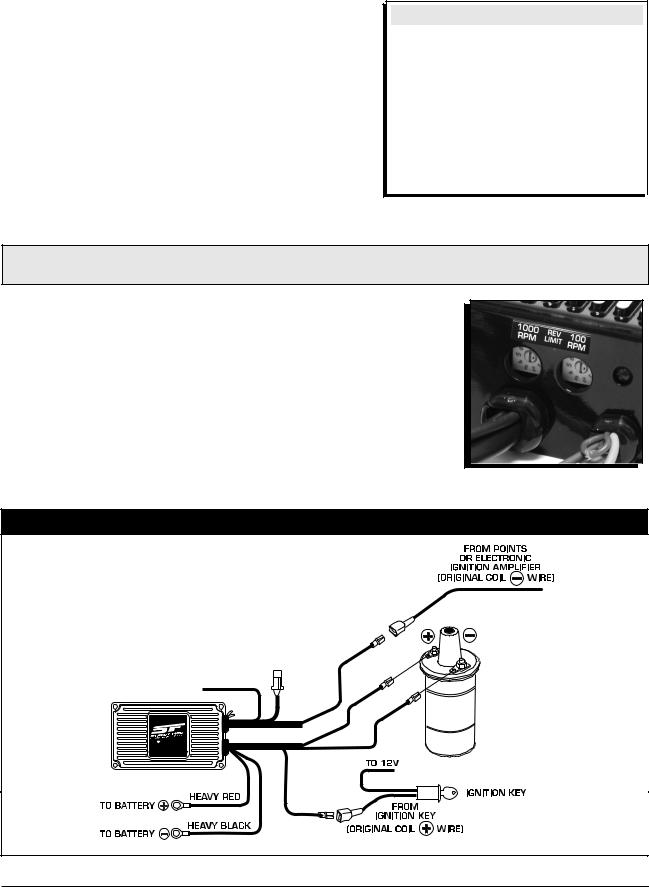
STREET FIRE SYSTEMS Installing to Points/Amplifier Style Ignition.
NOTE: On dual point setups, it is recommended to remove the trailing set of points.
NOTE: Ballast Resistor is not necessary.
TO GRAY
TACH
®
|
RK |
CDI |
MULTI-SPA |
N |
|
|
IGNITIO |
PN 5520
WWW.STREET-FIRE.COM
MAGNETIC |
|
PICKUP |
WHITE |
NOT USED |
|
|
ORANGE |
|
BLACK |
SMALL
RED
|
NOTE: Remove the coil |
|
terminal wires.The negative |
|
wire connects to the Street |
|
Fire White.The positive wire |
|
connects to the Street Fire |
COIL |
Red.The Street Fire Orange |
|
connects to the coil positive |
|
terminal, Black connects to |
|
the coil negative terminal. |
S T R E E T F I R E • WWW . STREET - FIRE . COM • (915) 857 - 5200 • FAX (915) 857 - 3344

4 |
INSTALLATION INSTRUCTIONS |
|
|
MSD SYSTEMS Installing to an MSD Distributor.
|
NOTE: SEE FIGURE 2 FOR COMMON MAGNETIC PICKUPS. |
|
|||||
|
|
|
|
|
(NOT |
USED) |
|
|
|
|
|
WHITE |
|
|
|
|
|
|
|
|
|
|
|
|
|
TO |
GRAY |
ORANGE |
|
||
|
|
TACH |
|
||||
|
|
|
|
||||
|
|
|
|
|
|||
|
|
|
|
|
BLACK |
|
|
|
|
® |
|
|
|
|
|
|
|
-SPARK |
|
|
|
|
DISTRIBUTOR |
|
|
CDI MULTI |
|
|
|
|
|
|
|
IGNITION |
|
|
|
|
|
|
|
PN 5520 |
|
|
|
|
WITH |
|
|
WWW.STREET-FIRE.COM |
|
|
|
|
|
|
|
|
|
SMALL |
|
|
MAGNETIC PICKUP |
|
|
|
|
|
|
|
|
|
|
|
|
RED |
|
|
|
|
GM IGNITIONS |
Wiring a Dual Connector Coil. |
|
||||
TO GRAY
TACH
®
CDI |
-SPARK |
MULTI |
|
|
IGNITION |
PN 5520
WWW.STREET-FIRE.COM
SMALL
RED
|
|
RED |
|
BOTH PINKS |
|
RED |
|
|
|||
|
WHITE
BLACK
ORANGE
NOTE: For a direct plug-in, use MSD Harness PN 8876.
NOTE: Cut and splice the two Pink wires (coil positive) together and connect to Orange wire of the ignition. Cut and splice the twoWhite wires (coil negative) together and connect to the White of the ignition. If the vehicle is not equipped with a factory tach, there will only be one White wire.
GM IGNITIONS |
Wiring with an MSD Wiring Harness. |
|
|||||
|
|
|
|
|
|
Harness PN 8876 - Dual Connector Coil. |
|
|
|
|
|
|
|
Harness PN 8877 - 1996-on GM Vehicles. |
|
|
|
|
|
MAGNETIC |
|
|
|
|
|
|
|
PICKUP |
|
|
|
|
|
|
|
NOT USED |
|
|
|
|
|
TO |
GRAY |
|
|
|
|
|
|
TACH |
|
|
|
||
|
|
|
|
WHITE |
|
|
|
|
|
® |
|
|
|
|
|
|
|
-SPARK |
|
SMALL RED |
|
|
|
|
CDI MULTI |
|
|
|
|
||
|
|
IGNITION |
|
|
|
|
|
|
|
PN 5520 |
|
|
|
|
|
|
WWW.STREET-FIRE.COM |
|
|
|
|
|
|
S T R E E T |
F I R E • |
WWW . STREET - FIRE . COM |
• |
(915) 857 - 5200 • FAX (915) |
857 - 3344 |
||
 Loading...