


MSD DynaForce Starter,
Chevrolet SB and BB V8
Straight Mount, PN 5095, Staggered Mount, PN 50951
ONLINE PRODUCT REGISTRATION: Register your MSD product online and you’ll be entered in our monthly 8.5mm Super Conductor Spark Plug Wire give-away! Registering your product will help if there is ever a warranty issue with your product and helps the MSD R&D team create new products that you ask for! Go to www.msdperformance.com/registration.
IMPORTANT: Proper installation of the DynaForce Starter is important to the overall operation. Correct alignment of the starter pinion with the ring gear is needed to achieve the best operation and longevity from your starter. Please read the instructions before attempting the installation.
|
Parts Included: |
1 - Shim Ring |
|
|
|
|
|||
|
1 |
- Starter |
|
|
|
1 - Outer Shim |
|
||
|
2 |
- Mounting Bolts |
|
|
|
|
|
||
|
2 |
- Mounting Block Shims |
|
|
|
|
|
|
|
WARNING: Before installing the DynaForce Starter disconnect the battery cables. When disconnecting the battery cables, always remove the Negative (-) cable first and install it last.
1.Make sure the starter mounting flange on the engine block is clean and smooth.
2.Install the starter with the supplied hardware. It is recommended to leave the shims out until the pinion gear to ring gear teeth mesh is checked. Torque the bolts to 32 lb-ft.
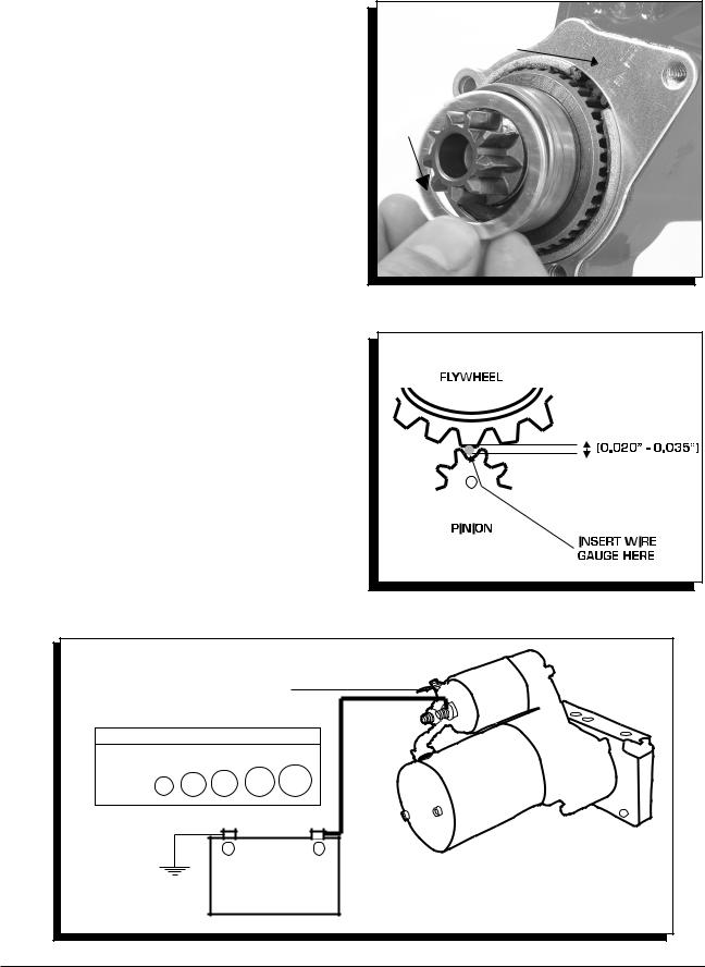
3.Check that the position of the solenoid is away from direct heat sources and other components. If there are clearance problems, the starter housing can be rotated to move the location of the solenoid. This is done by removing the three bolts on the mounting block and repositioning the starter motor (Figure 1).
4.With the starter installed, check the clearance between the ring gear and the edge of the pinion gear (Figure 2). There should be at least 1/16". It is recommended to check this clearance in at least three places around the flex plate.
•If there is not enough clearance, you will need to install the supplied shim kit by removing the mounting block (Figure 3). Place the small shim ring in the bearing bore and install the outer shim on the support housing. Reinstall the mounting block. This will move the pinion gear into the starter approximately 0.060".
CLOCKING
LOCATIONS
Figure 1 Clocking the Starter for Clearance.
Figure 2 Checking Pinion Clearance.
M S D • W W W . M S D P E R F O R M A N C E . C O M • ( 9 1 5 ) 8 5 7 - 5 2 0 0 • F A X ( 9 1 5 ) 8 5 7 - 3 3 4 4
2 |
INSTALLATION INSTRUCTIONS |
|
|
5.To check the pinion gear mesh, gently pry the gear out to engage to the ring gear. (Sometimes the pinion will not retract. This is normal.) Insert a wire gauge as shown in Figure 4. As a gauge, a standard 1.25" paperclip could be used as they generally are about .035" in diameter. There should be .020"-.035" clearance between the ring gear tooth and the pinion gear.
•If there is not enough clearance, install one of the supplied shims and check again.
•If there is too much clearance, install a shim under the outer bolt only. This will tighten the clearance.
6.The switch wire that connects to the solenoid should be at least 12-gauge (Figure 5).
Note: If your original starter had wire going to a second terminal, an ‘R’ terminal, this can generally be bypassed. See the information on page 3 of the instructions for more details.
7.Attach the battery cable. The size of the battery cable depends on its length. Using the proper gauge wire is important to the operation of the starter. Both the positive and ground wires must be able to meet the demands of the starter. The chart in Figure 5 shows the recommended sizes. Be sure to route the wire away from the exhaust and moving parts of the engine.
8.Connect the battery terminals and start the engine.
IMPORTANT: Never operate a starter for more than 30 seconds at a time without letting it cool for at least two minutes.
INSTALL OUTER
SHIM
SHIM
RING
Figure 3 Installing the Pinion Shim Spacers.
Figure 4 Checking Gear Mesh.
|
|
|
12-GAUGE MINIMUM |
||
|
|
|
TO IGNITION |
||
|
|
|
SWITCH |
|
|
CABLE LENGTH VS. GAUGE |
|
||||
LENGTH |
3’ |
5’ |
7’ |
10’ |
+10’ |
AWG |
4 |
2 |
1 |
0 |
00 |
|
|
|
- |
|
+ |
|
|
|
|
BATTERY |
|
Figure 5 Wiring the Starter.
M S D • W W W . M S D P E R F O R M A N C E . C O M • ( 9 1 5 ) 8 5 7 - 5 2 0 0 • F A X ( 9 1 5 ) 8 5 7 - 3 3 4 4
 Loading...