


7531
Programmable Digital-7 Plus
PN 7531
ONLINE PRODUCT REGISTRATION: Register your MSD product online and you’ll be entered
in our monthly 8.5mm Super Conductor Spark Plug Wire give-away! Registering your product
will help if there is ever a warranty issue with your product and helps the MSD R&D team create
new products that you ask for! Go to www.msdperformance.com/registration.
Parts Included:
1 - Ignition Control, PN 7531
1 - MSD Pro-Data+ CD Rom
4 - Vibration Mounts & Screws
1 - Shielded Cam Sync Harness
1 - 9-Pin Computer Harness
Accessories
Hand Held Monitor, PN 7550
Inductive Cam Sync Pickup Kit, PN 7555
Non-Magnetic Cam Sync Pickup Kit,
PN 2346
Manual Launch RPM Control, PN 7551
Digital Shift Light, PN 7542
WARNING: During installation, disconnect the battery cables. When disconnecting, always remove
the Negative cable first and install it last.
1 - Mag Pickup Harness, PN 8860
1 - 12-Pin Harness
1 - Coil Harness
1 - Power Lead Harness
MAP Sensor, see page 9
Replacement Harness, PN 8855
Single Pole/Single Throw Relay, PN 8961
Double Pole/Double Throw Relay, PN 8960
Note: Solid core spark plug wires cannot be used with an MSD Ignition Control.
OPERATION
DIGITAL OPERATION
The MSD Programmable Digital-7 Plus uses a high speed RISC microcontroller to control the ignition’s output
while constantly analyzing the various inputs such as supply voltage, trigger signals and rpm. The high speed
controller can make extremely quick compensations to the output voltage, multiple spark series, timing and rpm
limits while maintaining accurate timing signals to within +/- 0.1° and +/- 10 rpm. The circuits and controller of
the ignition have been thoroughly debounced and suppressed to create protection against Electro Magnetic
Interference (EMI).
CAPACITIVE DISCHARGE
The MSD features a capacitive discharge ignition design. The majority of stock ignition systems are inductive ignitions.
In an inductive ignition, the coil must store energy and step up the supplied voltage to maximum strength between
each firing. At higher rpm, since there is less time to charge the coil to full capacity, the secondary voltage falls short
of reaching its maximum energy level which results in a loss of power or top end miss.
The MSD Ignition features a capacitor which is quickly charged to 520 - 535 volts and stores its energy until the
ignition is triggered. With the CD design, the energy sent to the coil is always at maximum power even at high rpm.
MULTIPLE SPARKS
The MSD produces full power multiple sparks for each firing of a plug. The number of multiple sparks that occur
decreases as rpm increases, however the spark series always lasts for 21° of crankshaft rotation. Above 3,300 rpm
there is simply not enough “time” to fire the spark plug more than once, so there is only one powerful spark.
M S D • W W W . M S D P E R F O R M A N C E . C O M • ( 9 1 5 ) 8 5 7 - 5 2 0 0 • F A X ( 9 1 5 ) 8 5 7 - 3 3 4 4
2 INSTALLATION INSTRUCTIONS
PROTECTION
The MSD Programmable Digital-7 Plus has a built in reverse polarity protection circuit. This will protect the ignition
in the event of wrong connections. It will also shut off for protection from a surge in power. The ignition will still
operate once the surge or polarity is corrected.
LED INDICATOR
There is an LED that monitors the status of the Ignition. The LED will verify trigger inputs and will flash trouble
codes such as a Code 2-blinks for No Cam Sync or Code 3-blinks for Low Battery supply voltage.
CAMSHAFT SYNCHRONIZATION
This is used only in applications where the individual cylinder timing is going to be used. The 2-pin connector
with a Light Blue and Light Green wire connects to a sensor that is used to synchronize or alert the Ignition as to
when the number one cylinder is going to be triggered. With this information, the Ignition knows which cylinder
is being fired allowing for the individual cylinder timing capabilities. MSD offers two kits to use for sync signals:
Universal Cam Sync Sensor, PN 2346 and a Fiber Optic Inductive Pickup Kit, PN 7555.
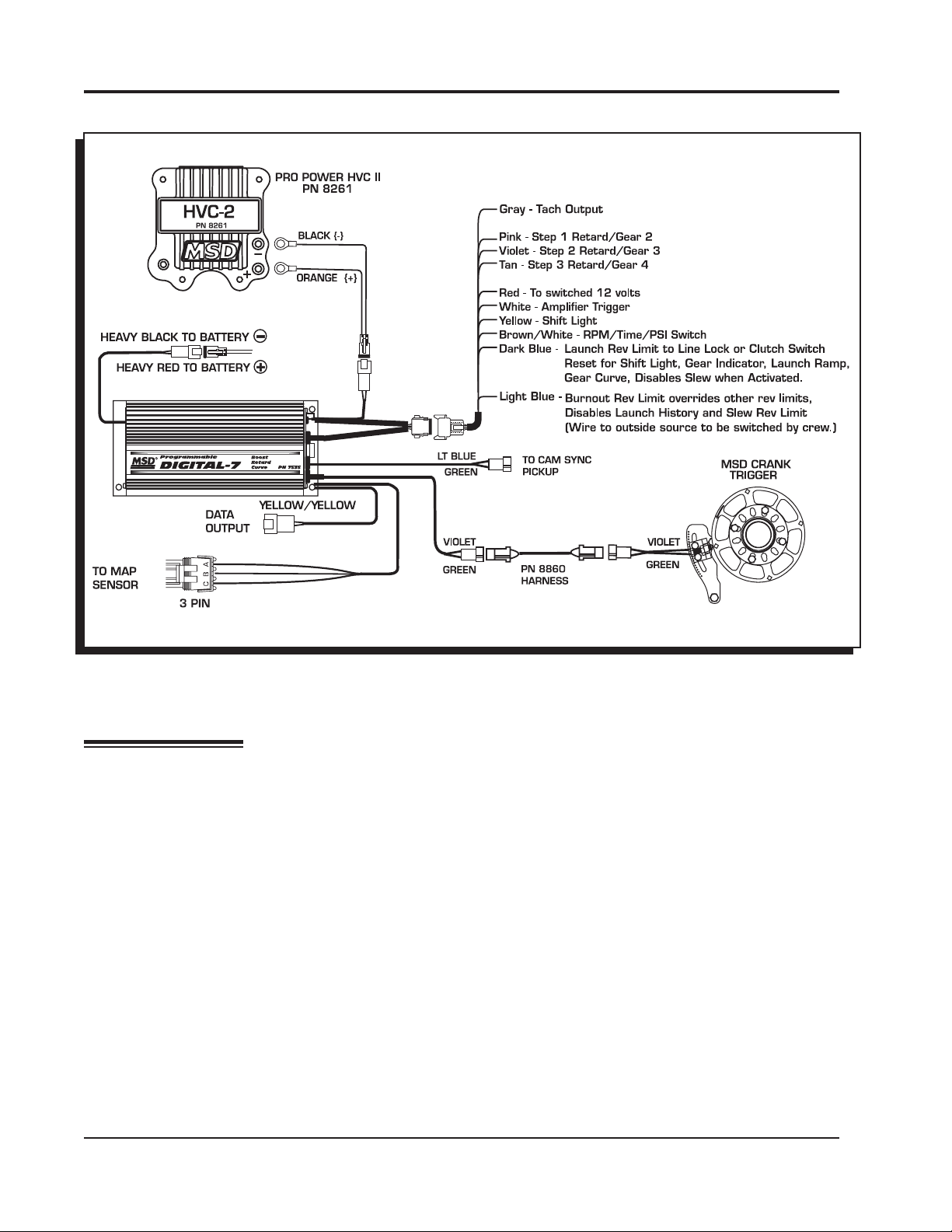
WIRING
Heavy
Ignition supply wire. Connects to battery positive (+) terminal or battery junction.
Red
Note: Do not connect to the alternator.
Heavy
Ignition supply Ground wire. Connect to battery negative (-) terminal or engine block.
Black
Red On/Off switch wiring. Connects to a switched 12 volt source.
Primary Coil Leads
Orange Connects to the coil positive (+) terminal. This is the only wire that makes contact to
the coil positive terminal.
Black Connects to the coil negative (-) terminal. This is the only wire that makes contact to
the coil negative terminal.
WARNING: High voltage is present at the coil primary terminals. Do not touch the coil or
connect test equipment to the terminals while the engine is running or cranking.
Trigger Wires
Violet/ Magnetic pickup, 2-pin connector. Plugs into an MSD Distributor or Crank Trigger
pickup. Violet is positive, Green is negative. Note: When this connector is used, the
Green
White wire is not connected.
2-Pin
White Trigger input for electronic ignition amplifiers, an ECU’s trigger or points.
Note: When this wire is used, the magnetic pickup wire is not connected.
Tach Output
Gray Tach output. This wire will provide the same 12 volt square wave tach signal as the
tach terminal on the side of the unit.
M S D • W W W . M S D P E R F O R M A N C E . C O M • ( 9 1 5 ) 8 5 7 - 5 2 0 0 • F A X ( 9 1 5 ) 8 5 7 - 3 3 4 4

INSTALLATION INSTRUCTIONS 3
Accessories
Dark Blue This wire activates the Launch Rev Limit and is the main reset wire for several features of the
Ignition. When 12 volts are applied to this wire it will activate the Launch Rev Limit. It also resets
the shift light and gear indicator to first gear. It also will select the Launch Retard value and Gear
1 curve. When 12 volts is removed, the Launch Ramp begins as does the Gear 1 curve.
When12 volts are applied the Slew Rate Rev limit will be disabled as well as the Timed Rev Limit
curve. When 12 volts are removed the Launch History begins recording.
Light Blue Burnout Rev Limit. When 12 volts are applied the Burnout Rev Limit is active. This disables the
Acquisition function and Slew Rate Rev Limits and overrides other rev limits. It also resets the
Acquisition Record function.
It is recommended to have this wire switched from an outside source, such as the crew chief before
the burnout and while staging the car.
Spool-Up When the Dark Blue and Light Blue wires are applied to 12 volts at the same time, a fourth rev
Limit
These three wires can be used as Retard Stage Activation and/or as a gear select wire.
Pink Step1 retard enabled with +12 volt input and above Step1 Rpm value and Gear 2 Select.
limit is activated. This limit is to spool up a turbo during the burnout. When both the Dark Blue
and Light Blue RevLimit wires are at +12 volts then the Spool RevLimit is active.
Retard Stage Wires or Gear Select
Violet Step2 retard enabled with +12 volt input and above Step2 Rpm value and Gear 3 Select.
Tan Step3 retard enabled with +12 volt input and above Step3 Rpm value and Gear 4 Select.
Note: When activated at the same time, these retard stages are added together. They are also
added with any Gear Retard Curve or Boost Retard values as well. Maximum retard is 30°.
Yellow Shift Light output wire. It can handle up to 3 amps continuous to ground when enabled.
Brown/White RPM/Time/Pressure switch output wire. It can switch up to 3 amps continuous to ground
when enabled.
Yellow/Yellow Output for data acquisition or fuel controls. Note, only two wires are used.
3-Pin Connector, MAP Sensor
Connector Connects to an external MAP or gauge pressure sensor.
Brown/Violet +5 volt supply
Brown/Yellow Ground
Dark Brown Map Signal
Cam Synchronization
Fiber Optic This input requires the PN 7555 Inductive Sync Pickup. When this input is used, the 2-pin con-
nector is not. Note: If this input is not used, the plug or a cover should be installed.
2-Pin Connector
Lt Blue/ This 2-pin plug connects to Cam Sync Sensor, PN 2346, to indicate when cylinder number
Lt Green
M S D • W W W . M S D P E R F O R M A N C E . C O M • ( 9 1 5 ) 8 5 7 - 5 2 0 0 • F A X ( 9 1 5 ) 8 5 7 - 3 3 4 4
one is firing. Note: When used, the fiber optic connector is not used and must be covered.
4 INSTALLATION INSTRUCTIONS
Figure 1 Wiring the Programmable Digital-7 Plus Ignition.
PRO-DATA+
INSTALLATION OF THE PRO-DATA+ SOFTWARE
1. Insert the installation CD Rom into the CD drive, wait up to 30 seconds, the CD will auto run, IF
THIS DOES NOT OCCUR:
Locate and open the CD Drive.
Double click on the autorun.exe file.
2. Select “Click here to Install Version X.XX”.
3. Once loaded, your monitor will have an MSD Pro-Data Plus X.XX logo. Accept the agreement.
Drive the installation to your program files folder, press the enter key. The installation will complete,
select OK.
4. A window will be opened with two aliases, double-click on the MSD GraphView alias to launch
the software. In the GraphView window, drag down on file and open. This will display a listing of
different part number folders. Open the 7531 folder and select your version. Double clicking the
version will launch the Pro-Data+ software for the Programmable Digital-7 Plus Ignition.
SAVES AND TRANSFERS
Whenever a change is made to a program, it either must be saved to a file in your PC or it needs to
be transferred to the ignition. You will notice that whenever you make a change to a program, the
bullet next to the modified value will turn red. It will remain red until you save it to a file or to the MSD.
There are two ways to save your files.
M S D • W W W . M S D P E R F O R M A N C E . C O M • ( 9 1 5 ) 8 5 7 - 5 2 0 0 • F A X ( 9 1 5 ) 8 5 7 - 3 3 4 4

INSTALLATION INSTRUCTIONS 5
Save to MSD: This step will save any changes directly into the ignition. If you are only making
one or just a couple modifications this works well.
Save to PC: This will save your changes to only show on the PC screen (indicated by a red
bullet point next to any altered values). These modifications will not be active or saved until
you save the file or transfer the information to the MSD.
You can create numerous files on your PC and download them for testing purposes or by saving
programs you used at different races or test sessions.
MONITOR
SOFTWARE
VERSION
IGNITION
MONITORED
NOTES
LIST
MENU
TREE
TACH
TIMING
ACQUIRED INFORMATION
HISTORY FILES
LAUNCH
REV LIMIT
BOOST CURVE
HISTORY TRACES
HISTORY
ANALYZE
GEAR TRACES
GEAR RETARD
BOOST
ICM
CURVES
GAUGE
Figure 2 Pro-Data+ Screen and Program Windows.
PROGRAMMABLE FEATURES
The following explains the programmable features of the PN 7531 Ignition. The features are listed in the
same order that they show on the Data Editor list in the software. Note that all of the retard amounts are
cumulative and the maximum amount of retard is 30°. The gear curves are independent.
STATS
Stat 1: This is only used with the Hand Held Monitors, PN 7550, PN 7553.
M S D • W W W . M S D P E R F O R M A N C E . C O M • ( 9 1 5 ) 8 5 7 - 5 2 0 0 • F A X ( 9 1 5 ) 8 5 7 - 3 3 4 4

6 INSTALLATION INSTRUCTIONS
REV LIMITS
Up to four different rev limits can be programmed in 100 rpm increments.
RevBurn: Burnout Rev Limit. This limit is activated when 12 volts are applied to the Light Blue
wire. It is adjustable from 2,000 to 12,500 rpm. Note that the Slew Rev Limiter is disabled by
the Burnout Limit.
RevLaunch: Launch Rev Limit. This limit is activated when 12 volts are applied to the Dark
Blue wire. It is adjustable from 2,000 to 12,500 rpm.
RevMax: Max Speed Rev Limit. This is the overrev limit and is active whenever the Launch
and BurnOut limits are off.
OutCam: Select either a Cam Sync output or a Rev Limiting output that can be used with
MSD components that use rpm modules for the rev limit, or data acquisition units.
AdjOff: This program enables an automatic compensating rev limiter that will
correct trigger input offsets and variables. It can be turned On or Off.
RPM: Adjustable in 100 rpm increments from 2,000 – 12,500.
Spool-Up: This program gives turbo cars a fourth rev limit to help the engine spool boost
pressure prior to the burnout. It is active when both the Light and Dark Blue wires are applied
to 12 volts at the same time. It is adjustable in 100 rpm increments from 2,000- 12,500. Default
is 3,000 rpm.
Note: See page 15 for information and examples on how to wire the rev limits.
REVLIMIT CURVE
This program allows you to map an rpm limiting curve based on time. It is programmed in graph view
on the Rev Limit chart and is adjustable in 100 rpm increments down to 0.01 seconds for up to 12.5
seconds.
Pt 1: Adjust from the Rev Limit chart of graph view (up to 32 points).
Time .00: Adjust from the Rev Limit chart of graph view.
RPM: Adjust from the Rev Limit chart of graph view.
RPM SLEW
This program provides an rpm limiting function based on a ratio between engine rpm and time. The
result is a programmable rate of acceleration for each gear. You can program the rate at which the
engine accelerates by selecting an rpm per second. If 3,000 rpm is selected, that means the engine
will be limited to 3,000 rpm per second. This is adjustable for each gear.
Gear 1: The RPM Slew rate for each gear. Adjustable from 1-6.
RPMSlew: The rpm amount per second, adjustable from 100 – 9,900 rpm per second in 100
rpm increments. Note that this Slew rate is disabled when the Launch or Burnout rev limits
are active.
Note: The Slew Rev Limiter is not recommended with distributor triggers. A crank trigger should be used.
MARGIN
The Slew Margin is a program to ensure very accurate rev limiting action especially when an engine accelerates quickly. There is a High and Low Margin value that ranges from 100-990 rpm.
The Margins should be programmed close to the Slew depending on the engine’s acceleration
M S D • W W W . M S D P E R F O R M A N C E . C O M • ( 9 1 5 ) 8 5 7 - 5 2 0 0 • F A X ( 9 1 5 ) 8 5 7 - 3 3 4 4
 Loading...