


8572
MSD Pro-Billet Chevrolet V8
Tach Drive Distributor
PN 8571
with Vacuum Advance, PN 8572
Important: Read these instructions before attempting the installation.
Note: An MSD Ignition is required with this Distributor.
Parts Included:
1 - Pro-Billet Distributor
1 - Rotor, PN 8467
1 - Distributor Cap, PN 8433
1 - Wire Retainer
2 - 1.5" Self Tapping Screws
2 - 10-32 x 3/4" Socket Head Screws
WARNING: Before installing the MSD Distributor, disconnect the battery cables. When
disconnecting the battery cables, always remove the Negative (-) cable first
and install it last.
Note: The cap of this Distributor requires spark plug style terminals. You may need to change the
terminals and boots of your wires. MSD offers two kits, PN 8849 or PN 8848 that are supplied
with nine boots and terminals. A socket style cap is available as PN 8437.
Note: If the gear is ever replaced, MSD Gear (PN 8531) is required for replacement due to the
.500" diameter shaft.
1 - Advance Kit
1 - Gasket
1 - Tube of Gear Lubricant
2 - O-Rings
1 - Vacuum Advance Lock-Out Kit
(PN 8572 Only)
1 - Gear Drive Adapter
TIMING FUNCTIONS
Before continuing with the installation, here are a few definitions you should be aware of:
Initial Timing: This is the base timing (also referred to as idle timing) of the engine before the
centrifugal advance begins.
Centrifugal Advance: The centrifugal (or mechanical) advance mechanism is made up of weights,
springs, advance cams, and an advance stop bushing. The amount and rate of advance that
your distributor is capable of is determined by the centrifugal timing. If you ever wish to lock out
the centrifugal advance, refer to the centrifugal advance section.
Total Timing: This is the total of the initial timing plus the centrifugal advance added together.
Example: 10° Initial + 25° centrifugal = 35° Total Timing (When checking Total timing, disconnect
the vacuum canister and plug the vacuum source).
Vacuum Advance (PN 8572 Only): The vacuum advance will advance the timing up to 10° during
partial throttle driving (with 15 lbs. of vacuum). The vacuum line should be routed to a ported
vacuum outlet above the throttle plates.
Note: MSD Distributors are supplied with the heavy (slow) advance springs installed. This is to
prevent detonation in certain applications. Review the information on pages 2-4 to determine
the best advance curve for your application.
M S D I G N I T I O N • ww w. ms d ig n it i on . co m • ( 91 5 ) 8 57 - 52 0 0 • FA X ( 915 ) 85 7- 33 4 4

2 INSTALLATION INSTRUCTIONS
CHOOSING AN ADVANCE CURVE
The function of the advance curve is to match the ignition timing to the burning rate of the fuel
and speed (rpm) of the engine. Any factor that changes the burning rate of the fuel or the engine
speed can cause a need for an ignition timing change. Figure 1 shows some of the factors that
will affect engine timing.
FACTOR Advance Timing Retard Timing
For For
Cylinder Pressure Low High
Vacuum High Low
Energy of Ignition Low High
Fuel Octane High Low
Mixture (Air/Fuel) Rich Lean
Temperature Cool Hot
Combustion Chamber Shape Open Compact
Spark Plug Location Offset Center
Combustion Turbulence Low High
Load Light Heavy
Figure 1 Ignition Timing Factors.
As you can see from the chart, most factors will change throughout the range of the engine
operation. The timing mechanism of the distributor must make timing changes based on these
factors.
Example: An engine has 11:1 compression with a high energy ignition. With the specifications
given, you will have to retard the timing for the high compression and high energy ignition. By
comparing the engine’s specifications against the chart, a usable timing guideline can be found.
Engines with a combination of items from both columns will require a timing that is set in the mid
range.
Obviously a full technical explanation of correct ignition timing would be very complicated. The
best way to arrive at a suitable ignition curve for your engine is to use the Ignition Timing Factors
Chart as a guide and compare it to the Advance Graphs in Figure 4 until a suitable curve is found.
When selecting your advance curve, use detonation (engine ping) as an indicator of too much
advance, and a decrease in power as an indicator of too little advance.
TIPS ON SELECTING AN ADVANCE CURVE
• Use as much initial advance as possible without encountering excessive starter load.
• Start the centrifugal advance just above the idle rpm.
• The starting point of the centrifugal advance curve is controlled by the installed length and
tension of the spring.
• How quickly the centrifugal advance (slope) comes in is controlled by the spring stiffness.
The stiffer the spring, the slower the advance curve.
• The amount of advance is controlled by the advance bushing. The bigger the bushing, the
smaller the amount of advance.
M S D I G N I T I O N • ww w. ms d ig n it i on . co m • ( 91 5 ) 8 57 - 52 0 0 • FA X ( 915 ) 85 7- 33 4 4
INSTALLATION INSTRUCTIONS 3
CENTRIFUGAL ADVANCE CURVE
SELECTING THE ADVANCE
SPRINGS
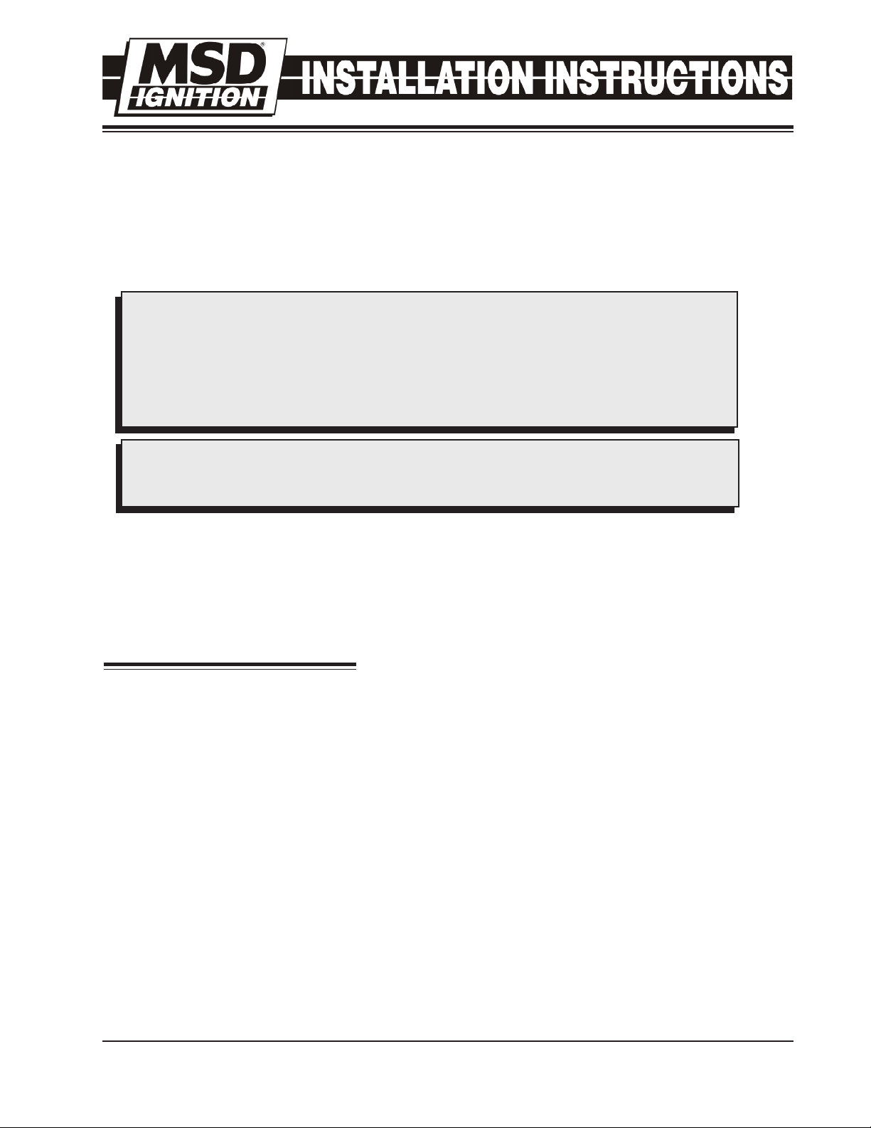
The rate, or how quick the advance comes
in is determined by the type of springs which
are installed on the distributor. The MSD
distributors are equipped with two Heavy
Silver springs installed. These will give you
the slowest advance curve possible (Figure
2). The parts kit contains two additional sets
of springs which can be used to match the
advance curve to your particular application.
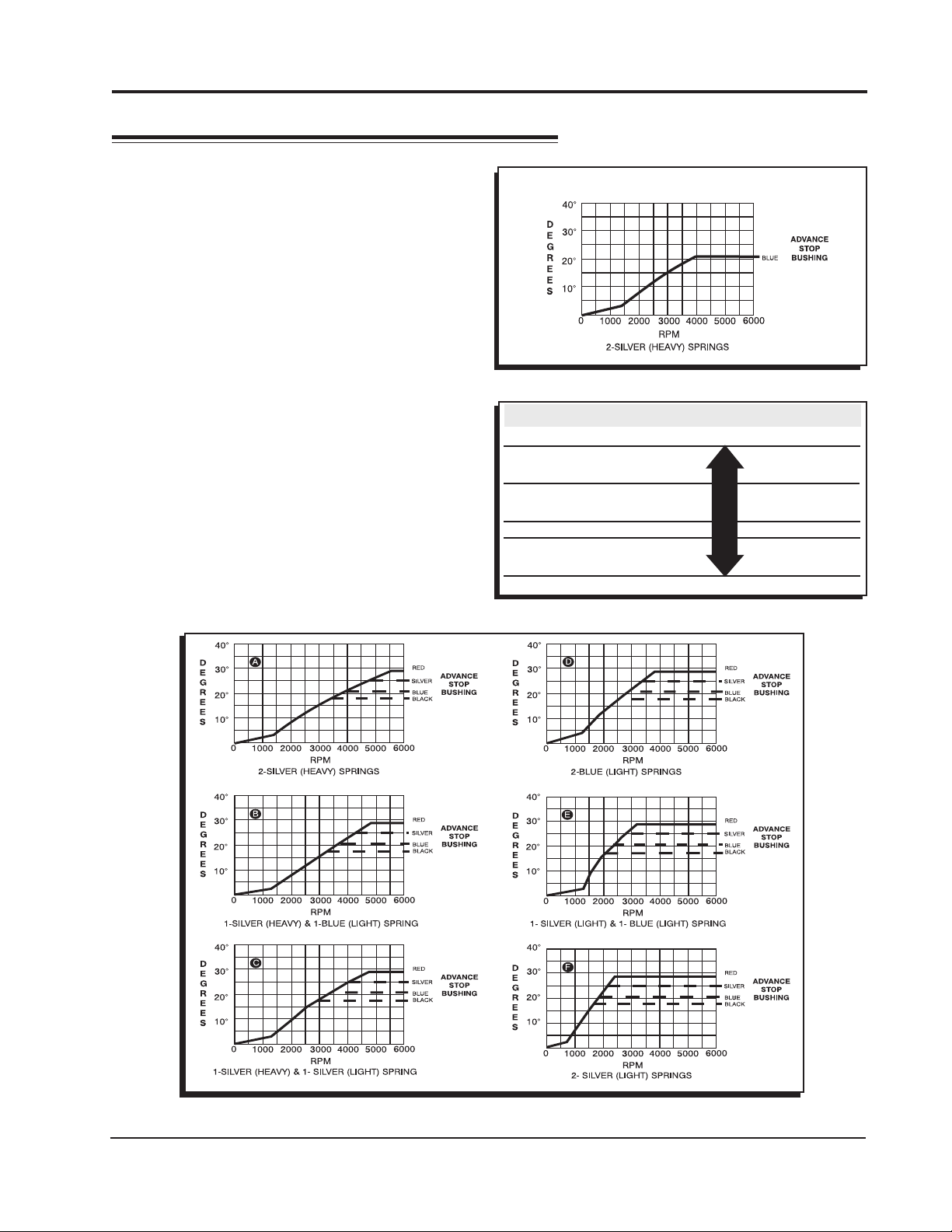
Refer to the Spring Combination Chart
(Figure 3) for combinations that can be
achieved.
To change the springs, remove the cap and
rotor and use needlenose pliers to remove
the springs. Be sure the new springs seat
in the groove on the pin.
SPRING COMBINATION RATE OF ADVANCE FIGURE 4
2- Heavy Silver SLOWEST A
1- Heavy Silver B
1- Light Blue
1-Heavy Silver C
1-Light Silver
2- Light Blue D
1- Light Silver E
1- Light Blue
2- Light Silver FASTEST F
Timing Curve From Factory
Figure 2 The Factory Equipped Curve.
Figure 3 Spring Combination Chart.
Figure 4 Advance Curves.
M S D I G N I T I O N • ww w. ms d ig n it i on . co m • ( 91 5 ) 8 57 - 52 0 0 • FA X ( 915 ) 85 7- 33 4 4
 Loading...