


Adjustable Timing Control
PN 8680
ONLINE PRODUCT REGISTRATION: Register your MSD product online and you’ll be entered in our monthly 8.5mm Super Conductor Spark Plug Wire give-away! Registering your product will help if there is ever a warranty issue with your product and helps the MSD R&D team create new products that you ask for! Go to www.msdperformance.com/registration.
IMPORTANT: Read the instructions before attempting installation.
|
Parts Included: |
|
|
|
|
|
|
|
|
||
|
1 |
- Timing Control, PN 8680 |
1 |
- Control Knob |
|
|
1 |
- 3/8" Bushing |
1 |
- 2-Pin Weathertight Connector |
|
|
4 |
- Self Tapping Screws |
|
|
|
|
|
|
|
|
|
|
|
|
|
|
|
WARNING: During installation, disconnect the battery cables. When disconnecting the battery, always remove the Negative cable first and install it last.
Note: The MSD PN 8680 Timing Control must be used with an MSD Ignition Control. It is recommended to install the MSD Ignition first.
MOUNTING
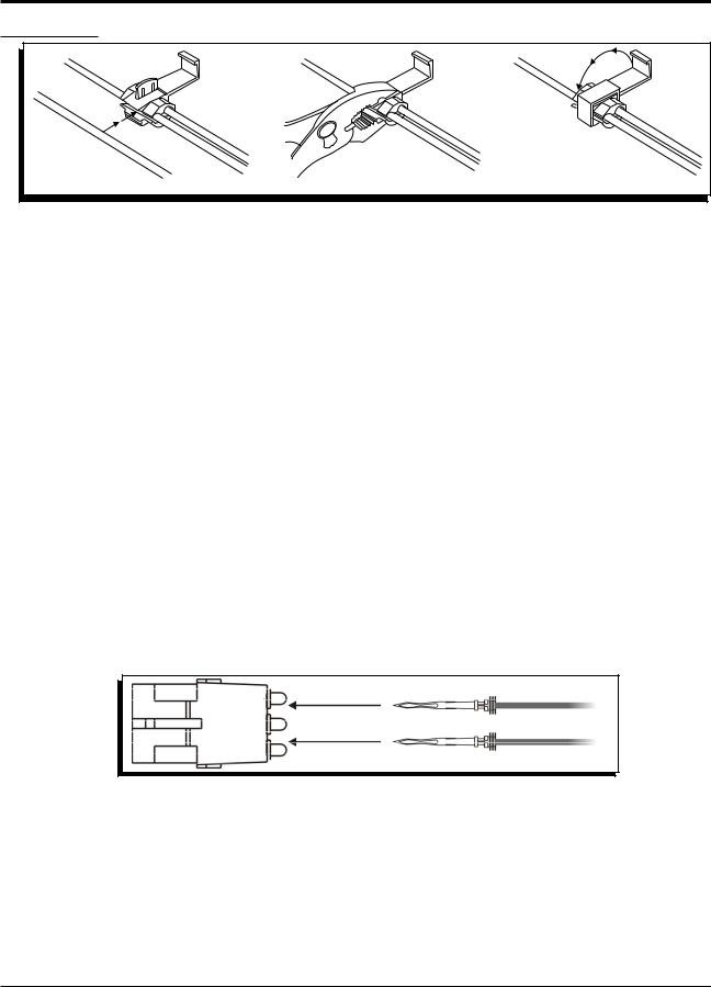
The Timing Computer may be mounted in the engine compartment as long as it is away from direct engine heat sources. Make sure all of the wires reach their connections before mounting the unit. Use the Control as a template and mark the mounting holes. Remove the unit and drill the mounting holes using an 1/8" drill bit. Four self tapping screws are supplied to mount the unit. Note: Before mounting the unit, install the supplied grommets and sleeves as shown in Figure 1.
PROGRAMMING
The Timing Control is programmed for 8-cylinder. If installing the PN 8680 on |
Figure 1 Installing the |
|||
Vibration Mounts. |
||||
a 4 or 6-cylinder, the Control must be programmed. |
|
|
||
|
|
|
||
Locate the Cylinder Select cover on the side of the |
|
|
|
|
unit and remove the single Phillips screw (Figure 2). |
CYLINDERS |
CUT LOOPS |
|
|
Number of Cylinders: The Red loop and the Blue |
|
|||
8 |
NONE |
|
||
loop are responsible for cylinder programming. The |
6 |
RED |
|
|
chart in Figure 2 shows which loop(s) to cut. |
4 |
RED AND BLUE |
|
|
|
|
|
||
Note: After cutting a loop, position the wire ends away from each other so they cannot make contact.
Figure 2 Selecting the Number of Cylinders.
M S D • W W W . M S D P E R F O R M A N C E . C O M • ( 9 1 5 ) 8 5 7 - 5 2 0 0 • F A X ( 9 1 5 ) 8 5 7 - 3 3 4 4
2 |
INSTALLATION INSTRUCTIONS |
WIRING |
|
WIRE FUNCTIONS
Figure 3 How to use the Supplied Wire Splice Device.
Yellow |
This is the trigger output wire. It connects to the White wire of an MSD 6 Series Ignition or |
|
“Points” terminal of a 7 Series Ignition. |
|
|
Red |
This wire is responsible for turning the Timing Control on and off. It connects to switched |
|
12 volt source. It can be spliced into the small red wire of the MSD. |
|
|
Black |
This is the ground wire and must be connected to a good engine or chassis ground. |
|
|
TRIGGER WIRES
Violet |
These wires connect to the magnetic pickup of the distributor or crank trigger. The |
Green |
Violet is positive (+) and the Green wire is negative (-). When this connector is used |
|
the White wire is not. |
|
|
White |
This is the trigger input wire for breaker points or ignition amplifier. When this wire is used, |
|
the magnetic pickup wires (violet and green) are not. |
|
|
Control Knob
The Black and Gray wires with the 2-Pin Weathertight connector are the Control Knob wires. After the Timing Control is mounted, the Harness should be routed to the unit. The Control Knob should be mounted within easy reach of the driver. Before mounting the Control Knob, make sure the wiring harness reaches the unit.
If the harness must be routed through the firewall, drill a 3/8" hole and use the supplied grommet to route the wires through. Install the supplied 2-Pin Weathertight connector to the wires after all of the routing is finished (Figure 4). The position of the wires in the connector is not important.
Figure 4 Installing the Weathertight Connector.
Operating the Control
After installation, it is recommended to check the timing. Before starting the vehicle, turn the Control Knob to the full 15° mark. This is the stock timing setting. As the Knob is turned counterclockwise, the timing retards. As detonation occurs, slowy retard the timing until the “pinging” noise is not audible. Adjust the timing as driving conditions change.
Resetting the Timing
It is possible to set the Timing Control up to where you can retard and advance the timing 7.5° each. To do this, position the Control Knob in the center (approximately 7.5°) then reset the timing to factory specifications.
M S D • W W W . M S D P E R F O R M A N C E . C O M • ( 9 1 5 ) 8 5 7 - 5 2 0 0 • F A X ( 9 1 5 ) 8 5 7 - 3 3 4 4

INSTALLATION INSTRUCTIONS |
3 |
|
|
DIAGRAMS
The following wiring diagrams show common installations.
NOTE: The MSD 5 and Blaster Ignitions are inductive designs and do not share the same wiring as the 6-Series Ignitions.
Figure 5 Wiring to a Points or Amplifier Ignition with an MSD 5 or Blaster Ignition using the Points Trigger.
ORIGINAL COIL+ WIRE |
|
|
|
|
|
FROM IGNITION |
|
|
|
||
|
KEY |
|
|
|
|
|
|
HEAVY RED |
TO BATTERY+ |
|
|
|
|
|
|
|
|
|
ORANGE |
HEAVY BLACK |
TO BATTERY- |
|
|
BLACK |
|
|
|
||
RED |
|
|
|
||
|
|
WHITE |
|
DIGITAL 6A |
|
POINTS |
|
|
|
|
|
OR AMPLIFIER |
|
|
|
GRAY TACH OUTPUT |
|
DISTRIBUTOR |
|
|
|
|
|
|
|
|
|
GREEN (-) |
|
ORIGINAL |
|
|
|
MAGNETIC PICKUP |
|
COIL- WIRE |
RED |
|
|
VIOLET (+) |
(NOT USED) |
|
|
|
|
||
|
YELLOW |
|
|
|
|
|
|
|
|
|
|
|
|
|
|
BLACK |
|
|
|
|
MAG PICKUP |
TO GROUND |
|
|
|
|
|
|
|
|
|
NOT USED |
|
|
|
|
WHITE |
|
|
|
|
|
|
TIMING |
|
|
|
|
|
CONTROL |
|
|
|
INDICATES CONNECTION USING |
|
|
|
|
|
WIRE SPLICE DEVICE |
|
|
|
|
|
|
|
ADVANCE |
|
|
|
|
|
|
|
TIMING |
|
|
|
|
|
CONTROL UNIT |
|
Figure 6 Wiring to Points or Amplifier Ignition with an MSD 6 Series.
M S D • W W W . M S D P E R F O R M A N C E . C O M • ( 9 1 5 ) 8 5 7 - 5 2 0 0 • F A X ( 9 1 5 ) 8 5 7 - 3 3 4 4
 Loading...