


|
|
|
|
|
|
|
|
|
|
|
|
|
|
|
|
|
|
|
|
|
|
|
|
|
|
|
|
|
|
|
|
|
|
|
|
|
|
|
|
|
|
|
|
|
|
|
|
|
|
|
|
|
|
|
|
|
|
|
|
|
|
|
|
|
|
|
|
|
|
|
|
|
|
|
|
|
|
|
|
|
|
|
|
|
|
|
|
|
|
|
|
|
|
|
|
|
|
|
|
|
|
|
|
|
|
|
|
|
|
|
|
|
|
|
|
|
|
|
|
|
|
|
|
|
|
|
|
|
|
|
|
|
|
|
|
|
|
|
|
|
|
|
|
|
1997 |
|
|||||||||||||||||
|
|
|
|
|
|
|
|
|
|
|
|
|
|
|
|
|
|
|
|
|
||||||||||||||||||||
|
|
|
|
|
|
|
|
|
|
|
|
|
|
|
|
|
|
|
|
|
||||||||||||||||||||
|
|
|
|
|
|
|
|
|
|
|
|
|
|
|
|
|
|
|
|
|
||||||||||||||||||||
|
|
|
|
|
|
|
|
|
|
|
|
|
|
|
|
|
|
|
|
|
||||||||||||||||||||
|
|
|
|
|
|
|
|
|
|
|
|
|
|
|
|
|
|
|
|
|||||||||||||||||||||
|
|
|
|
|
|
|
|
|
|
|
|
|
|
|
|
|
|
|
|
|||||||||||||||||||||
|
|
|
|
|
|
|
|
|
|
|
|
|
|
|
|
|
|
|
|
|||||||||||||||||||||
|
|
|
|
|
|
|
|
|
|
|
|
|
|
|
|
|
|
|
|
|||||||||||||||||||||
SPLIT-TYPE, HEAT PUMP, AIR CONDITIONERS |
||||||||||||||||||||||||||||||||||||||||
|
|
|
|
|
|
|
|
|
|
|
|
|
|
|
|
|
|
|
|
|
|
|
|
|
|
|
|
|
|
|
|
|
|
|
|
|
|
|
|
|
|
|
|
|
|
|
|
|
|
|
|
|
|
|
|
|
|
|
|
|
|
|
|
|
|
|
|
|
|
|
|
No. OC147 |
|||||||||
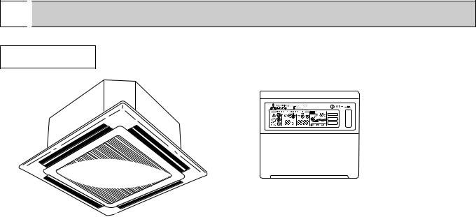
TECHNICAL & SERVICE MANUAL
Series PLH Ceiling Cassettes
Indoor unit [Model names]
PLH-1.6KKHB
PLH-2KKHB
PLH-2.5KKHB
[Service Ref.]
PLH-1.6KKHB·UK PLH-2KKHB·UK PLH-2.5KKHB·UK
This manual does not cover the following outdoor units. When servicing them, please refer to the service manual No.OC150 and this manual in a set.
[Service Ref.] PUH-1.6VKA3·UK PUH-2VKA2·UK PUH-2.5VKA2·UK
INDOOR UNIT
FILTER

 CHECK MODE
TEST RUN
CONTENTS |
|
|
1. |
FEATURES.......................................... |
2 |
2. PART NAMES AND FUNCTIONS ...... |
3 |
|
3. |
SPECIFICATIONS............................... |
6 |
4. |
DATA ................................................... |
9 |
5. OUTLINES AND DIMENSIONS........ |
13 |
|
6. WIRING DIAGRAM ........................... |
15 |
|
7. |
REFRIGERANT SYSTEM DIAGRAM ..... |
16 |
8. OPERATION FLOW-CHART ............ |
17 |
|
9. MICROPROCESSOR CONTROL..... |
21 |
|
10. TROUBLESHOOTING ...................... |
43 |
|
11. 4-WAY AIR FLOW SYSTEM ............. |
51 |
|
12. SYSTEM CONTROL ......................... |
52 |
|
13. DISASSEMBLY PROCEDURE ......... |
57 |
|
14. |
PARTS LIST...................................... |
60 |
15. |
OPTIONAL PARTS ........................... |
64 |
REMOTE CONTROLLER
The Slim Line.
From Mitsubishi Electric.
1 
 FEATURES
Series PLH Ceiling Cassettes
FILTER
CHECK MODE
TEST RUN
|
Indoor unit |
Remote controller |
|
|
|
||
|
|
|
|
Service Ref. |
Cooling capacity/Heating capacity |
||
|
|
||
W |
Btu/h |
||
|
|||
|
|
|
|
PLH-1.6KKHB.UK |
4,400/4,650[6,050] |
15,000/15,900[20,600] |
|
|
|
|
|
PLH-2KKHB.UK |
5,400/5,800[7,200] |
18,400/19,800[24,600] |
|
|
|
|
|
PLH-2.5KKHB.UK |
6,300/[7,200/9,300] |
21,500/24,600[31,700] |
|
|
|
|
|
1.PURSUING CONPACTNESS
(1)Panel size and body volume reduced to 64% of previous models
The width and depth of the panel have been reduced by 19cm respectively, resulting in a compact model which fits smaller environments (like shops) perfectly.
(2)Multi-application panels flexibly adapt to installation conditions.
Space panel and Wide panel may be installed on ceilings with shallow depth using the exiting opening .
2."SMUDGE-FREE", PRECISELY TARGETED AIRFLOW SYSTEM
The new control system regulates airflow to prevent smudging. A projection inside the air passage distributes air evenly over the top and bottom of the vane. Two projections on the air outlet work to prevent cooled air from rising to the celling, and also to stop outside air being dragged into the cooled air stream.
3.AIRFLOW ADJUSTABLE TO ANY INDOOR ENVIRONMENT
Airflow can be adjusted according to celling height and the number of air outlets. "Wide Zoming Flow" creates anoptimum airflow for any indoor environment.
4.A FURTHER REFINEMENT OF COMFORT WITH NOISE SUPPRESION
The celling 4-way airflow cassette has a special "silent-design". The "2-Tap"system allows a choice between silent and standard modes according to the height of the cellig. For ordinary residenced which have a low celling, selection of the silent mode will result in remarkable noise reductions.
5.ECONOMICAL AND EASY MAINTENANCE
(1)Push-open grill
Filter clogging is widely recognized as a cause of reduced perfomance, but up until now it has been troublesome to clean filters. With the "push-open grill" the fillter can be smoothly opened out at the push of a button, enabling speedy cleaning.
(2)An unprecedented level of vane-cleaning
The unique airflow system prevents the intake of indoor air. Dewing therefore does not occur, and the vane is flockless. The resulting level of dirt on the vane due to tobacco smoke, dust, etc. is very light,and can be wiped off easily with a neutral detergent
(3)Long-life fillter
This new celling 4-way airflow cassette employs a long life fillter which requires no maintenance for up to 2,500 hours of operation in general office environments. It adds uo to an ideal blend of comfort and low maintenance.
2
6.COMPACT DIMENSIONS MEAN EASY INSTALLATION
(1)Carefree suspension work with lightweight unit
The new unit weighs in at 20kg (9kg lighter than the previous model) and is easy to handle and install. What's more, suspension work is facillitated by compact dimensions ensuring a snug fit.
(2)Smooth installation with "one-direction"bolts
Suspension bolts can be fixes consistently from one direction easing suspension work.
(3)Trouble-free fitting work with slender refrigerant piping
Refrigerant piping has been reduced in size, and pipe-curving work at the installation site can now be completed quickly and economically. In addition, refrigerant and drain piping are set at different corners, which means that flare connections and drain piping heat insulation work can be smoothly and reliably implemented.
(4)Easy-access terminal and control panels for efficient wiring
When performing wiring work, progress can be checked on the power source terminal and control panels simply by removing the electrical parts cover. Adress setting can also be done easily from beneath at a convenient angle.
(5)"One-push"to provisionally position front panel
Panel weight has been redused from 7kg to 3.7kg. The previous 3-step process for provisionally positioning the panel has been streamlined, and now a simple "one-push" action at the diagonal corners fixed it into place, resulting in major time-saving.
2 
 PART NAMES AND FUNCTIONS
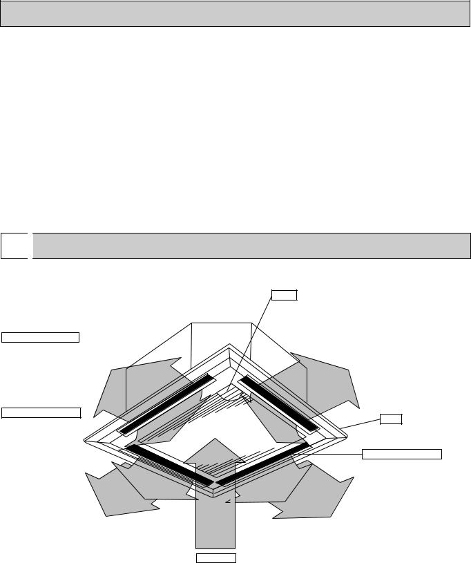
● Indoor (Main) Unit
PLH-1.6KKHB·UK
PLH-2KKHB·UK
PLH-2.5KKHB·UK
Horizontal Air Outlet
Sets airflow horizontal automatically during cooling or dehumidifying.
Downward Air Outlet Sets airflow downward automatically during heating.
Filters
Remove dust and pollutants from inhaled air
Grill
Auto Air Swing Vane Disperses airflow up and down and adjusts the angle of airflow direction.
Air Intake
Inhales air from room.
3
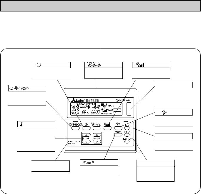
● Remote controller
Once the controls are set, the same operation mode can be repeated by simply pressing the ON/OFF button.
● Operation buttons
|
button |
button |
|
This switches between |
This sets or switches the |
||
continuous operation and the |
current time. start time and |
||
timer operation. |
stop time. |
||
button |
|
||
Press this button to switch |
|
||
the cooler electronic dry |
|
||
(dehumidify) automatic and |
|
||
heater modes. |
|
|
|
|
|
FILTER |
|
|
|
CHECK MODE |
|
|
|
TEST RUN |
|
TEMP button |
|
||
This sets the room |
|
||
temparature The temparature |
|
||
setting can be performed in |
|
||
1°C units |
|
|
|
Setting range |
4 |
||
Cooler |
19°C to 30°C |
||
|
|||
Heater |
17°C to 28°C |
|
|
This model name of the |
button |
||
remote controller is indicated. |
This switches the horizontal |
||
|
|
||
|
|
fan motion ON and OFF. |
|
|
|
(This button dose not operate in |
|
|
|
this model) |
|
button
This sets the ventilation fan speed.
ON/OFF button
This switches between the operation and stop modes each time it is pressed. The lamp on this butoon lights during operation.
button
This adjusts the vertical angle of the ventilation.
FILTER button
This resets the filter service indication display.
CHECK-TEST RUN button
Only press this button to perform an inspection check or test operation. Do not use it for normal operation.
4
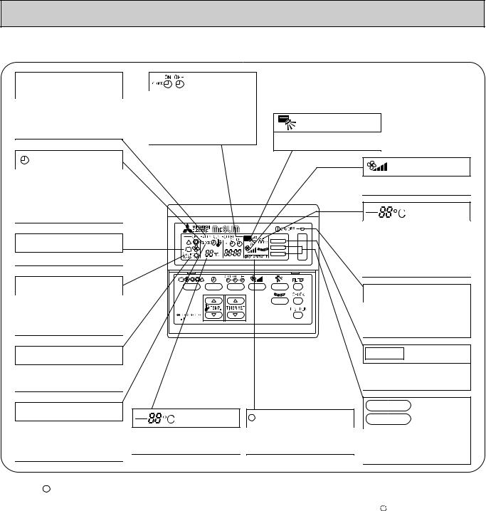
● Display
CENTRALLY CONTROLLED display
This indicates when the unit is controlled by optional features such as central control type remote controller.
display
The current time , start time and stop time can be displayed in tensecond intervals by pressing the time switch button. The start time or stop time is always displayed during the timer operation.
In this display example on the bottom left, a condition where all display lamps light is shown for explanation purposes although this differs from actual operation.
display
This displays the air direction.
display
This indicates when the continous operation and time operation modes are set.
It also display the time for the timer operation at the same time as when it is set.
OPERATION MODE display
This indicates the operation mode.
STANDBY display
This indicates when the standby mode is set from the time the sleep
operation starts until the heating air 
 240KA is discharged.
DEFROST display
This indicates when the defrost operation is performed.
CHECK display
display
This indicates when a malfunction has occurred in the unit which should
This displays the selected setting
be checked.
temperature.
|
display |
|
The selected fan speed is displayed. |
|
display |
|
The temperature of the suction air is |
|
displayed during operation. The |
FILTER |
display range is 8° to 39°C. The |
CHECK MODE |
display flashes 8°C when the actual |
TEST RUN |
temperature is less than 8° and |
|
|
|
flashes 39°C when the actual |
|
temperature is greater than 39°C. |
|
Operation lamp |
|
This lamp lights during operation, |
|
goes off when the unit stops and |
|
flashes when amalfunction occurs. |
 display
This lamp lights when electricity is supplied to the unit.
FILTER Display
This lamp lights when the filter need to be cleaned.
CHECK MODE
display
TEST RUN
This display lights in the check mode or when a test operation is performed.
Caution
●Only the  display lights when the unit is stopped and power supplied to the unit.
●When power is turned ON for the first time the (CENTRAL CTRL) display appears to go off momentarily but this is not a malfunction.
●When the central control remote control unit, which is sold separately, is used the ON-OFF button, 


 button and
  TEMP button do not operate.
●“NOT AVAILABLE” is displayed when the k button are pressed.This indicates that this room unit is not equipped with the fan direction adjustment function and the louver function.
5
3 |
|
SPECIFICATIONS |
|
||
|
|
|
|
|
Service Ref. |
|
|
|
|
|
|
Item |
|
|
|
|
|
Function |
|
|
|
||
Capacity |
|
|
Btu/h |
||
|
|
W |
|||
|
|
|
|
|
|
Total input |
|
|
kW |
||
|
Service Ref. |
|
|
|
|
|
Power supply(phase, cycle,voltage) |
|
|||
|
|
Input |
|
|
kW |
|
|
Running current |
|
|
A |
|
|
Starting current |
|
|
A |
|
External finish |
|
|
|
|
UNIT |
Heat exchanger |
|
|
kW |
|
|
Fan motor output |
|
|
||
|
|
Fan(drive) x No. |
|
|
|
INDOOR |
Booster heater |
|
|
kW |
|
|
|
Airflow(Low-High) |
|
|
K/min(CFM) |
|
|
External static pressure |
|
mmAq,Pa |
|
|
Operation control & Thermostat |
|
|
|
|
|
|
|
|
||
|
Noise level(Low-High) |
|
|
dB(A) |
|
|
Cond. drain conn. O.D. |
|
|
mm,(in.) |
|
|
|
|
W |
|
mm,(in.) |
|
Dimensions |
D |
|
mm,(in.) |
|
|
|
|
H |
|
mm,(in.) |
|
Weight |
|
|
kg,(lbs) |
|
|
Service Ref. |
|
|
|
|
|
Power supply (phase, cycle, voltage) |
|
|||
|
|
Input |
|
|
kW |
|
|
Running current |
|
|
A |
|
|
Starting current |
|
|
A |
|
External finish |
|
|
|
|
|
Refrigerant control |
|
|
|
|
|
Compressor |
|
|
|
|
UNIT |
|
Model |
|
|
|
|
Motor output |
|
|
kW |
|
OUTDOOR |
|
Fan(drive) x No. |
|
|
|
|
|
Starter type |
|
|
|
|
|
Protection devices |
|
|
|
|
Heat exchanger |
|
|
|
|
|
|
Fan motor output |
|
|
kW |
|
|
|
|
||
|
|
Airflow |
|
|
K/min(CFM) |
|
Defrost method |
|
|
|
|
|
Noise level |
|
|
dB(A) |
|
|
|
|
W |
|
mm,(in.) |
|
Dimensions |
D |
|
mm,(in.) |
|
|
|
|
H |
|
mm,(in.) |
|
Weight |
|
|
kg,(lbs) |
|
PIPING |
Refrigerant |
|
|
|
|
|
Charge |
|
|
kg,(lbs) |
|
|
|
|
|
||
REEFRIGERANT |
Pipe size O.D. |
Liquid |
|
mm,(in.) |
|
Gas |
|
mm,(in.) |
|||
|
|
||||
|
|
|
|
||
|
Connection method |
Indoor side |
|
||
|
Outdoor side |
||||
|
|
|
|||
|
Between the indoor & outdoor unit |
Height difference |
|||
|
|
|
Piping length |
||
|
PLH-1.6KKHB.UK |
|
Cooling |
|
Heating |
|
||
15,000 |
|
15,900[20,600] |
4,400 |
|
4,650[6,050] |
1.59 |
|
1.51[2.91] |
|
PLH-1.6KKHB.UK |
|
|
Single. 50Hz. 220-240V |
|
0.15 |
|
0.10[1.50] |
0.64 |
|
0.45[6.28] |
0.70 |
|
0.50[6.63] |
Galvanized sheets with gray heat insulation
Plate fin coil
Turbo fan (direct) x 1
0.030
13-16(460-565)
0(direct blow)
[1.4]
Remote controller & built-in
32-37
32(1-1/4)
UNIT : 660(26) |
PANEL : 760(30) |
UNIT : 660(26) |
PANEL : 760(30) |
UNIT : 253(10) |
PANEL : 30(1-1/8) |
UNIT : 20(44) |
PANEL :3.7(8) |
|
PUH-1.6VKA3.UK |
|
|
Single. 50Hz. 220-240V |
|
1.44 |
|
1.41 |
6.74 |
|
6.60 |
33
Munsell 5Y 7/1
Capillary tube
Hermetic
RH247VFC
1.2
Line start
Inner thermostat, High pressure switch
Plate fin coil
Propeller (direct) x1
0.065
45(1,590)
Reverse cycle
49
870(34-1/4)
295+24 (11-5/8 add 1)
650(25-5/8)
53(117)
R-22
2.2(4.8)
9.52 (3/8)
15.88(5/8)
Flared
Flared
Max. 40m
Max. 40m
6

Service Ref.
Item
Function
Capacity |
|
Btu/h |
||
|
W |
|||
|
|
|
||
Total input |
|
kW |
||
|
Service Ref. |
|
|
|
|
Power supply(phase, cycle,voltage) |
|
||
|
Input |
|
kW |
|
|
Running current |
|
A |
|
|
Starting current |
|
A |
|
|
External finish |
|
|
|
UNIT |
Heat exchanger |
|
kW |
|
Fan motor output |
|
|||
|
Fan(drive) x No. |
|
|
|
INDOOR |
Booster heater |
|
kW |
|
|
Airflow(Low-High) |
|
K/min(CFM) |
|
|
External static pressure |
mmAq,Pa |
||
|
Operation control & Thermostat |
|
|
|
|
|
|
||
|
Noise level(Low-High) |
|
dB(A) |
|
|
Cond. drain conn. O.D. |
|
mm,(in.) |
|
|
|
W |
mm,(in.) |
|
|
Dimensions |
D |
mm,(in.) |
|
|
|
H |
mm,(in.) |
|
|
Weight |
|
kg,(lbs) |
|
|
Service Ref. |
|
|
|
|
Power supply (phase, cycle, voltage) |
|
||
|
Input |
|
kW |
|
|
Running current |
|
A |
|
|
Starting current |
|
A |
|
|
External finish |
|
|
|
|
Refrigerant control |
|
|
|
|
Compressor |
|
|
|
UNIT |
Model |
|
|
|
Motor output |
|
kW |
||
OUTDOOR |
Fan(drive) x No. |
|
|
|
|
Starter type |
|
|
|
|
Protection devices |
|
|
|
|
Heat exchanger |
|
|
|
|
Fan motor output |
|
kW |
|
|
|
|||
|
Airflow |
|
K/min(CFM) |
|
|
Defrost method |
|
|
|
|
Noise level |
|
dB(A) |
|
|
|
W |
mm,(in.) |
|
|
Dimensions |
D |
mm,(in.) |
|
|
|
H |
mm,(in.) |
|
|
Weight |
|
kg,(lbs) |
|
PIPING |
Refrigerant |
|
|
|
Charge |
|
kg,(lbs) |
||
|
|
|||
REEFRIGERANT |
Pipe size O.D. |
Liquid |
mm,(in.) |
|
Gas |
mm,(in.) |
|||
|
||||
|
|
|||
|
Connection method |
Indoor side |
|
|
|
Outdoor side |
|||
|
|
|||
|
Between the indoor & outdoor unit |
Height difference |
||
|
|
Piping length |
||
|
PLH-2KKHB.UK |
|
Cooling |
|
Heating |
|
||
18,400 |
|
19,800[24,600] |
5,400 |
|
5,800[7,200] |
2.34 |
|
2.32[3.72] |
|
PLH-2KKHB.UK |
|
|
Single. 50Hz. 220-240V |
|
0.14 |
|
0.10[1.50] |
0.65 |
|
0.45[6.28] |
0.72 |
|
0.50[6.63] |
Galvanized sheets with gray heat insulation
Plate fin coil
Turbo fan (direct) x 1
0.030
13-16(460-565)
0(direct blow)
[1.4]
Remote controller & built-in
32-37
32(1-1/4)
UNIT : 660(26) |
PANEL : 760(30) |
UNIT : 660(26) |
PANEL : 760(30) |
UNIT : 253(10) |
PANEL : 30(1-1/8) |
UNIT : 20(44) |
PANEL :3.7(8) |
|
PUH-2VKA2.UK |
|
|
Single. 50Hz. 220-240V |
|
2.20 |
|
2.22 |
9.86 |
|
9.95 |
45
Munsell 5Y 7/1
Capillary tube
Hermetic
NH38VMD
1.7
Line start
Inner thermostat, HP switch
Plate fin coil
Propeller (direct) x1
0.065
45(1590)
Reverse cycle
49
870(34-1/4)
295+24 (11-5/8 add 1)
650(25-5/8)
64(141)
R-22
2.2(4.8)
9.52 (3/8)
15.88(5/8)
Flared
Flared
Max. 40m
Max. 40m
7

Service Ref.
Item
Function
Capacity |
|
Btu/h |
||
|
W |
|||
|
|
|
||
Total input |
|
kW |
||
|
Service Ref. |
|
|
|
|
Power supply(phase, cycle,voltage) |
|
||
|
Input |
|
kW |
|
|
Running current |
|
A |
|
|
Starting current |
|
A |
|
|
External finish |
|
|
|
UNIT |
Heat exchanger |
|
kW |
|
Fan motor output |
|
|||
|
Fan(drive) x No. |
|
|
|
INDOOR |
Booster heater |
|
kW |
|
|
Airflow(Low-High) |
|
K/min(CFM) |
|
|
External static pressure |
mmAq,Pa |
||
|
Operation control & Thermostat |
|
|
|
|
|
|
||
|
Noise level(Low-High) |
|
dB(A) |
|
|
Cond. drain conn. O.D. |
|
mm,(in.) |
|
|
|
W |
mm,(in.) |
|
|
Dimensions |
D |
mm,(in.) |
|
|
|
H |
mm,(in.) |
|
|
Weight |
|
kg,(lbs) |
|
|
Service Ref. |
|
|
|
|
Power supply (phase, cycle, voltage) |
|
||
|
Input |
|
kW |
|
|
Running current |
|
A |
|
|
Starting current |
|
A |
|
|
External finish |
|
|
|
|
Refrigerant control |
|
|
|
|
Compressor |
|
|
|
UNIT |
Model |
|
|
|
Motor output |
|
kW |
||
OUTDOOR |
Fan(drive) x No. |
|
|
|
|
Starter type |
|
|
|
|
Protection devices |
|
|
|
|
Heat exchanger |
|
|
|
|
Fan motor output |
|
kW |
|
|
|
|||
|
Airflow |
|
K/min(CFM) |
|
|
Defrost method |
|
|
|
|
Noise level |
|
dB(A) |
|
|
|
W |
mm,(in.) |
|
|
Dimensions |
D |
mm,(in.) |
|
|
|
H |
mm,(in.) |
|
|
Weight |
|
kg,(lbs) |
|
PIPING |
Refrigerant |
|
|
|
Charge |
|
kg,(lbs) |
||
|
|
|||
REEFRIGERANT |
Pipe size O.D. |
Liquid |
mm,(in.) |
|
Gas |
mm,(in.) |
|||
|
||||
|
|
|||
|
Connection method |
Indoor side |
|
|
|
Outdoor side |
|||
|
|
|||
|
Between the indoor & outdoor unit |
Height difference |
||
|
|
Piping length |
||
|
PLH-2.5KKHB.UK |
|
Cooling |
|
Heating |
|
||
21,500 |
|
24,600[31,700] |
6,300 |
|
7,200[9,300] |
2.60 |
|
2.33[4.43] |
|
PLH-2.5KKHB.UK |
|
|
Single. 50Hz. 220-240V |
|
0.14 |
|
0.10[2.20] |
0.61 |
|
0.45[9.20] |
0.67 |
|
0.50[9.55] |
Galvanized sheets with gray heat insulation
Plate fin coil
Turbo fan (direct) x 1
0.030
14-17(495-600)
0(direct blow)
[2.1]
Remote controller & built-in
35-39.5
32(1-1/4)
UNIT : 660(26) |
PANEL : 760(30) |
UNIT : 660(26) |
PANEL : 760(30) |
UNIT : 253(10) |
PANEL : 30(1-1/8) |
UNIT : 21(46) |
PANEL :3.7(8) |
|
PUH-2.5VKA2.UK |
|
|
Single. 50Hz. 220-240V |
|
2.46 |
|
2.23 |
10.68 |
|
9.78 |
52
Munsell 5Y 7/1
Capillary tube
Hermetic
NH41VMD
2.0
Line start
Inner thermostat, HP switch
Plate fin coil
Propeller (direct) x1
0.085
50(1764)
Reverse cycle
52
870(34-1/4)
295+24 (11-5/8 add 1)
850(34-1/4)
68(150)
R-22
2.8(6.2)
9.52 (3/8)
15.88(5/8)
Flared
Flared
Max. 50m
Max. 50m
8
4 |
|
|
DATA |
|
|
|
|
|
|
|
|
|
|
|
|
|
|
|
|
|
|
|
|
|
|
|
|
|
|
|
|
|
|
|
||||
|
|
|
|
|
|
|
|
|
|
|
|
|
|
|
|
|
|
|
|
|
|
|
|
|
|
|
|
|
|
|
|
|
|
|
|
|||
1. PERFORMANCE DATA |
|
|
|
|
|
|
|
|
|
|
|
|
|
|
|
|
|
|
|
|
|
|
|
|
|
|
|
|
||||||||||
1) COOLING CAPACITY |
|
|
|
|
|
|
|
|
|
|
|
|
|
|
|
|
|
|
|
|
|
|
|
|
|
|
|
|
|
|
|
|||||||
|
|
|
|
|
|
|
|
|
|
|
|
|
|
|
|
|
|
|
|
|
|
|
|
|
|
|
|
|
|
|
|
|
|
|
|
|||
|
|
|
|
|
|
Indoor |
|
|
|
|
|
|
|
|
|
|
|
Outdoor intake air DB C |
|
|
|
|
|
|
|
|
|
|
|
|||||||||
|
Service Ref. |
|
|
intake |
20 |
|
|
|
25 |
|
30 |
|
|
|
|
|
35 |
40 |
|
|
|
|
|
45 |
|
|||||||||||||
|
|
|
air |
|
|
|
|
|
|
|
|
|
|
|
|
|
|
|
||||||||||||||||||||
|
|
|
|
|
|
|
|
|
|
|
|
|
|
|
|
|
|
|
|
|
|
|
|
|
|
|
|
|
|
|
|
|
|
|
|
|
|
|
|
|
|
|
|
|
|
WB C |
|
CA |
|
P.C. |
|
CA |
|
P.C. |
|
CA |
|
P.C. |
|
CA |
|
P.C. |
|
CA |
|
P.C. |
|
CA |
|
P.C. |
|
||||||
|
|
|
|
|
|
|
|
|
|
|
|
|
|
|
|
|
|
|
|
|
|
|
|
|
|
|
|
|
|
|
|
|
|
|
|
|
|
|
|
|
|
|
|
|
16 |
4,439 |
|
1.27 |
|
4,317 |
|
|
1.33 |
4,159 |
|
1.43 |
|
3,990 |
|
1.53 |
3,812 |
|
1.64 |
|
3,624 |
|
1.74 |
|
|||||||||
|
|
|
|
|
|
|
|
|
|
|
|
|
|
|
|
|
|
|
|
|
|
|
|
|
|
|
|
|
|
|
|
|
|
|
|
|
|
|
|
PLH-1.6KKHB.UK |
|
18 |
4,726 |
|
1.30 |
|
4,602 |
|
|
1.36 |
4,434 |
|
1.46 |
|
4,258 |
|
1.57 |
4,074 |
|
1.68 |
|
3,882 |
|
1.79 |
|
||||||||||||
|
|
|
|
|
|
|
|
|
|
|
|
|
|
|
|
|
|
|
|
|
|
|
|
|
|
|
|
|
|
|
|
|
|
|
||||
|
|
20 |
5,017 |
|
1.32 |
|
4,899 |
|
|
1.38 |
4,724 |
|
1.50 |
|
4,542 |
|
1.61 |
4,352 |
|
1.72 |
|
4,154 |
|
1.84 |
|
|||||||||||||
|
|
|
|
|
|
|
|
|
|
|
|
|
|
|
|
|
||||||||||||||||||||||
|
|
|
|
|
|
|
|
|
|
|
|
|
|
|
|
|
|
|
|
|
|
|
|
|
|
|
|
|
|
|
|
|
|
|
|
|
|
|
|
|
|
|
|
|
22 |
5,310 |
|
1.35 |
|
5,209 |
|
|
1.41 |
5,028 |
|
1.53 |
|
4,840 |
|
1.65 |
4,645 |
|
1.77 |
|
4,442 |
|
1.90 |
|
|||||||||
|
|
|
|
|
|
|
|
|
|
|
|
|
|
|
|
|
|
|
|
|
|
|
|
|
|
|
|
|
|
|
|
|
|
|
|
|
|
|
|
|
|
|
|
|
16 |
5,448 |
|
1.88 |
|
5,299 |
|
|
1.96 |
5,104 |
|
2.11 |
|
4,897 |
|
2.26 |
4,678 |
|
2.41 |
|
4,447 |
|
2.56 |
|
|||||||||
|
PLH-2KKHB.UK |
|
18 |
5,800 |
|
1.91 |
|
5,648 |
|
|
2.00 |
5,442 |
|
2.15 |
|
5,226 |
|
2.31 |
5,000 |
|
2.47 |
|
4,764 |
|
2.63 |
|
||||||||||||
|
|
20 |
6,157 |
|
1.95 |
|
6,012 |
|
|
2.04 |
5,798 |
|
2.20 |
|
5,574 |
|
2.37 |
5,341 |
|
2.54 |
|
5,099 |
|
2.71 |
|
|||||||||||||
|
|
|
|
|
|
|
|
|
|
|
|
|
|
|
|
|
||||||||||||||||||||||
|
|
|
|
|
|
|
|
|
|
|
|
|
|
|
|
|
|
|
|
|
|
|
|
|
|
|
|
|
|
|
|
|
|
|
|
|
|
|
|
|
|
|
|
|
22 |
6,517 |
|
1.99 |
|
6,392 |
|
|
2.08 |
6,171 |
|
2.25 |
|
5,940 |
|
2.42 |
5,700 |
|
2.61 |
|
5,451 |
|
2.80 |
|
|||||||||
|
|
|
|
|
|
|
|
|
|
|
|
|
|
|
|
|
|
|
|
|
|
|
|
|
|
|
|
|
|
|
|
|
|
|
|
|
|
|
|
|
|
|
|
|
16 |
6,356 |
|
2.08 |
|
6,182 |
|
|
2.17 |
5,955 |
|
2.34 |
|
5,713 |
|
2.51 |
5,472 |
|
2.68 |
|
5,207 |
|
2.85 |
|
|||||||||
|
|
|
|
|
|
|
|
|
|
|
|
|
|
|
|
|
|
|
|
|
|
|
|
|
|
|
|
|
|
|
|
|
|
|
|
|
|
|
|
PLH-2.5KKHB.UK |
|
18 |
6,767 |
|
2.13 |
|
6,589 |
|
|
2.22 |
6,349 |
|
2.39 |
|
6,097 |
|
2.57 |
5,841 |
|
2.74 |
|
5,571 |
|
2.92 |
|
||||||||||||
|
|
|
|
|
|
|
|
|
|
|
|
|
|
|
|
|
|
|
|
|
|
|
|
|
|
|
|
|
|
|
|
|
|
|
||||
|
|
20 |
7,183 |
|
2.17 |
|
7,014 |
|
|
2.26 |
6,764 |
|
2.45 |
|
6,503 |
|
2.63 |
6,232 |
|
2.82 |
|
5,954 |
|
3.01 |
|
|||||||||||||
|
|
|
|
|
|
|
|
|
|
|
|
|
|
|
|
|
||||||||||||||||||||||
|
|
|
|
|
|
|
|
|
|
|
|
|
|
|
|
|
|
|
|
|
|
|
|
|
|
|
|
|
|
|
|
|
|
|
|
|
|
|
|
|
|
|
|
|
22 |
7,603 |
|
2.21 |
|
7,458 |
|
|
2.31 |
7,199 |
|
2.50 |
|
6,930 |
|
2.69 |
6,645 |
|
2.90 |
|
6,359 |
|
3.11 |
|
|||||||||
Note CA:Capacity (W) |
|
|
|
|
|
|
|
|
|
|
|
|
|
|
|
|
|
|
|
|
|
|
|
|
|
|
|
|
|
|
|
|||||||
|
|
P.C.:Power consumption (kW) |
|
|
|
|
|
|
|
|
|
|
|
|
|
|
|
|
|
|
|
|
|
|
|
|
|
|
|
|
||||||||
Cooling capacity correction factors |
|
|
|
|
|
|
|
|
|
|
|
|
|
|
|
|
|
|
|
|
|
|
|
|
|
|
|
|
||||||||||
|
|
|
|
|
|
|
|
|
|
|
|
|
|
|
|
|
|
|
|
|
|
|
|
|
|
|
|
|
|
|
|
|||||||
|
|
Service Ref. |
|
|
|
|
|
|
|
|
|
|
|
Refrigerant piping length(one way) |
|
|
|
|
|
|
|
|
|
|
|
|||||||||||||
|
|
|
|
|
|
|
|
|
|
|
|
|
|
|
|
|
|
|
|
|
|
|
|
|
|
|
|
|
|
|
|
|
|
|
||||
|
|
|
5m |
|
10m |
|
|
15m |
|
|
20m |
|
25m |
|
|
30m |
|
|
35m |
|
40m |
|
|
45m |
|
|
50m |
|
||||||||||
|
|
|
|
|
|
|
|
|
|
|
|
|
|
|
|
|
|
|
|
|
|
|||||||||||||||||
|
|
|
|
|
|
|
|
|
|
|
|
|
|
|
|
|
|
|
|
|
|
|
|
|
|
|
|
|||||||||||
|
PLH-1.6KKHB.UK |
|
1.00 |
|
0.993 |
|
|
0.984 |
|
|
0.978 |
|
0.969 |
|
|
0.961 |
|
0.956 |
|
0.948 |
|
|
— |
|
|
— |
|
|||||||||||
|
|
|
|
|
|
|
|
|
|
|
|
|
|
|
|
|
|
|
|
|
|
|
|
|
|
|
|
|||||||||||
|
PLH-2KKHB.UK |
|
1.00 |
|
0.992 |
|
|
0.983 |
|
|
0.978 |
|
0.966 |
|
|
0.959 |
|
0.950 |
|
0.945 |
|
|
— |
|
|
— |
|
|||||||||||
|
|
|
|
|
|
|
|
|
|
|
|
|
|
|
|
|
|
|
|
|
|
|
|
|
|
|||||||||||||
|
PLH-2.5KKHB.UK |
|
1.00 |
|
0.989 |
|
|
0.980 |
|
|
0.970 |
|
0.960 |
|
|
0.950 |
|
0.940 |
|
0.930 |
|
0.920 |
|
0.910 |
|
|||||||||||||
|
|
|
|
|
|
|
|
|
|
|
|
|
|
|
|
|
|
|
|
|
|
|
|
|
|
|
|
|
|
|
|
|
|
|
|
|
|
|
Cooling performance curve(50Hz)
TOTAL INPUT (RATIO) CAPACITY (RATIO)
1.4 |
|
|
|
|
|
1.0 |
|
|
|
|
22 |
|
|
|
|
|
20 |
0.8 |
|
|
|
|
18 |
|
|
|
|
16 |
|
0.6 |
|
|
|
|
|
1.4 |
|
|
|
|
|
1.2 |
|
|
|
|
22 |
|
|
|
|
20 |
|
|
|
|
|
|
18 |
1.0 |
|
|
|
|
16 |
|
|
|
|
|
|
0.8 |
|
|
|
|
|
0.6 |
|
|
|
|
|
0.4 |
|
|
|
|
|
-5 |
5 |
15 |
25 |
35 |
46 |
1.2 |
|
OUTDOOR DB(°C) |
INDOOR WB(°C) |
||
INDOOR WB(°C)
9

2) HEATING CAPACITY
|
|
Indoor |
|
|
|
|
|
|
|
|
|
|
|
Outdoor intake air WB C |
|
|
|
|
|
|
|
|
|
|
||||||||
Service Ref. |
|
|
intake |
|
|
|
|
|
|
|
|
|
|
|
|
|
|
|
|
|
|
|
|
|
|
|
|
|
|
|
|
|
|
-10 |
|
|
|
-5 |
|
0 |
|
|
|
|
5 |
10 |
|
|
|
|
|
15 |
|||||||||||||
|
|
air |
|
|
|
|
|
|
|
|
|
|
|
|
|
|||||||||||||||||
|
|
|
|
|
|
|
|
|
|
|
|
|
|
|
|
|
|
|
|
|
|
|
|
|
|
|
|
|
|
|
|
|
|
|
|
DB C |
|
CA |
|
P.C. |
|
CA |
|
P.C. |
|
CA |
|
P.C. |
|
CA |
|
P.C. |
|
CA |
|
P.C. |
|
CA |
|
P.C. |
|||||
|
|
|
|
|
|
|
|
|
|
|
|
|
|
|
|
|
|
|
|
|
|
|
|
|
|
|
|
|
|
|
|
|
|
|
15 |
3,184 |
|
1.03 |
|
3,650 |
|
|
1.14 |
4,160 |
|
1.25 |
|
4,714 |
|
1.38 |
5,312 |
|
1.51 |
|
5,952 |
|
1.64 |
||||||||
|
|
|
|
|
|
|
|
|
|
|
|
|
|
|
|
|
|
|
|
|
|
|
|
|
|
|
|
|
|
|
|
|
PLH-1.6KKHB.UK |
|
20 |
3,049 |
|
1.11 |
|
3,506 |
|
|
1.23 |
4,003 |
|
1.35 |
|
4,538 |
|
1.48 |
5,112 |
|
1.62 |
|
5,724 |
|
1.77 |
||||||||
|
|
25 |
2,930 |
|
1.18 |
|
3,364 |
|
|
1.31 |
3,844 |
|
1.44 |
|
4,370 |
|
1.59 |
4,942 |
|
1.74 |
|
5,560 |
|
1.90 |
||||||||
|
|
|
|
|
|
|
|
|
|
|
|
|
|
|
|
|
|
|
|
|
|
|
|
|
|
|
|
|
|
|
|
|
|
|
15 |
3,972 |
|
1.58 |
|
4,552 |
|
|
1.75 |
5,188 |
|
1.93 |
|
5,880 |
|
2.11 |
6,625 |
|
2.31 |
|
7,424 |
|
2.52 |
||||||||
|
|
|
|
|
|
|
|
|
|
|
|
|
|
|
|
|
|
|
|
|
|
|
|
|
|
|
|
|
|
|
|
|
PLH-2KKHB.UK |
|
20 |
3,803 |
|
1.71 |
|
4,373 |
|
|
1.89 |
4,993 |
|
2.08 |
|
5,661 |
|
2.28 |
6,376 |
|
2.49 |
|
7,139 |
|
2.71 |
||||||||
|
|
25 |
3,655 |
|
1.81 |
|
4,196 |
|
|
2.01 |
4,795 |
|
2.22 |
|
5,451 |
|
2.44 |
6,165 |
|
2.67 |
|
6,935 |
|
2.91 |
||||||||
|
|
|
|
|
|
|
|
|
|
|
|
|
|
|
|
|
|
|
|
|
|
|
|
|
|
|
|
|
|
|
|
|
|
|
15 |
4,931 |
|
1.59 |
|
5,651 |
|
|
1.76 |
6,441 |
|
1.93 |
|
7,299 |
|
2.12 |
8,225 |
|
2.32 |
|
9,216 |
|
2.53 |
||||||||
|
|
|
|
|
|
|
|
|
|
|
|
|
|
|
|
|
|
|
|
|
|
|
|
|
|
|
|
|
|
|
|
|
PLH-2.5KKHB.UK |
|
20 |
4,721 |
|
1.71 |
|
5,429 |
|
|
1.89 |
6,198 |
|
2.09 |
|
7,027 |
|
2.29 |
7,916 |
|
2.50 |
|
8,863 |
|
2.73 |
||||||||
|
|
25 |
4,537 |
|
1.82 |
|
5,209 |
|
|
2.02 |
5,952 |
|
2.23 |
|
6,767 |
|
2.45 |
7,653 |
|
2.68 |
|
8,609 |
|
2.92 |
||||||||
|
|
|
|
|
|
|
|
|
|
|
|
|
|
|
|
|
|
|
|
|
|
|
|
|
|
|
|
|
|
|
|
|
Note CA:Capacity (W) |
|
|
|
|
|
|
|
|
|
|
|
|
|
|
|
|
|
|
|
|
|
|
|
|
|
|
|
|
|
|||
P.C.:Power consumption (kW) |
|
|
|
|
|
|
|
|
|
|
|
|
|
|
|
|
|
|
|
|
|
|
|
|
|
|
||||||
Heating capacity correction factors |
|
|
|
|
|
|
|
|
|
|
|
|
|
|
|
|
|
|
|
|
|
|
|
|
|
|
||||||
|
|
|
|
|
|
|
|
|
|
|
|
|
|
|
|
|
|
|
|
|
|
|
|
|
|
|
||||||
Service Ref. |
|
|
|
|
|
|
|
|
|
|
|
Refrigerant piping length(one way) |
|
|
|
|
|
|
|
|
|
|
||||||||||
|
|
|
|
|
|
|
|
|
|
|
|
|
|
|
|
|
|
|
|
|
|
|
|
|
|
|
|
|
|
|
||
|
5m |
|
10m |
|
|
15m |
|
|
20m |
|
25m |
|
|
30m |
|
35m |
|
40m |
|
|
45m |
|
|
50m |
||||||||
|
|
|
|
|
|
|
|
|
|
|
|
|
|
|
|
|||||||||||||||||
|
|
|
|
|
|
|
|
|
|
|
|
|
|
|
|
|
|
|
|
|
|
|
|
|
||||||||
PLH-1.6KKHB.UK |
|
1.00 |
|
1.00 |
|
|
1.00 |
|
|
1.00 |
|
1.00 |
|
|
1.00 |
0.998 |
|
0.995 |
|
|
— |
|
|
— |
||||||||
|
|
|
|
|
|
|
|
|
|
|
|
|
|
|
|
|
|
|
|
|
|
|
|
|
||||||||
PLH-2KKHB.UK |
|
1.00 |
|
1.00 |
|
|
1.00 |
|
|
1.00 |
|
1.00 |
|
|
1.00 |
0.998 |
|
0.995 |
|
|
— |
|
|
— |
||||||||
|
|
|
|
|
|
|
|
|
|
|
|
|
|
|
|
|
|
|
|
|
|
|
||||||||||
PLH-2.5KKHB.UK |
|
1.00 |
|
1.00 |
|
|
1.00 |
|
|
1.00 |
|
1.00 |
|
|
1.00 |
0.998 |
|
0.995 |
|
0.993 |
|
0.990 |
||||||||||
|
|
|
|
|
|
|
|
|
|
|
|
|
|
|
|
|
|
|
|
|
|
|
|
|
|
|
|
|
|
|
|
|
Heating performance curve(50Hz)
CAPACITY (RATIO)
TOTAL INPUT (RATIO)
1.4 |
|
|
|
|
|
|
|
|
|
15 |
|
|
|
|
|
|
|
|
|
||
|
|
|
|
|
|
|
|
|
|
|
|
|
|
|
|
|
|
|
|
|
20 |
1.2 |
|
|
|
|
|
|
|
|
|
25INDOOR DB ( C) |
|
|
|
|
|
|
|
|
|
||
1.0 |
|
|
|
|
|
|
|
|
|
|
|
|
|
|
|
|
|
|
|
|
|
0.8 |
|
|
|
|
|
|
|
|
|
|
|
|
|
|
|
|
|
|
|
|
|
0.6 |
|
|
|
|
|
|
|
|
|
|
|
|
|
|
|
|
|
|
|
|
|
1.4 |
|
|
|
|
|
|
|
|
|
25INDOOR DB ( C) |
|
|
|
|
|
|
|
|
|
||
1.2 |
|
|
|
|
|
|
|
|
|
|
|
|
|
|
|
|
|
|
|
20 |
|
|
|
|
|
|
|
|
|
|
||
|
|
|
|
|
|
|
|
|
|
15 |
1.0 |
|
|
|
|
|
|
|
|
|
|
|
|
|
|
|
|
|
|
|
|
|
0.8 |
|
|
|
|
|
|
|
|
|
|
|
|
|
|
|
|
|
|
|
|
|
0.6 |
|
|
|
|
|
|
|
|
|
|
|
|
|
|
|
|
|
|
|
|
|
0.4 |
|
|
|
|
|
|
|
|
|
|
|
|
|
0 |
5 10 15 |
|
|||||
-12-10 -5 |
|
|||||||||
OUTDOOR WB( C)
10
2. ELECTRICAL DATA
Indoor unit 220V 50Hz 1phase
Outdoor unit 220V 50Hz 1phase
Service Ref. |
Indoor unit |
PLH-1.6KKHB.UK |
PLH-2KKHB.UK |
PLH-2.5KKHB.UK |
|||||
|
|
|
|
|
|
|
|||
Outdoor unit |
PUH-1.6VKA3.UK |
PUH-2VKA2.UK |
PUH-2.5VKA2.UK |
||||||
|
|
||||||||
|
|
|
|
|
|
|
|
|
|
Mode |
|
|
Cool |
Heat |
Cool |
Heat |
Cool |
Heat |
|
|
|
|
|
|
|
|
|
||
Capacity (W) |
4,300 |
4,550[5,720] |
5,300 |
5,700[6,870] |
6,200 |
6,900[8,660] |
|||
|
|
|
|
|
|
|
|
||
Total Input (kW) |
1.48 |
1.40[2.57] |
2.24 |
2.22[3.39] |
2.53 |
2.25[4.01] |
|||
|
|
|
|
|
|
|
|
|
|
unit |
Input (kW) |
0.12 |
0.08[1.25] |
0.12 |
0.08[1.25] |
0.12 |
0.09[1.85] |
||
|
|
|
|
|
|
|
|
||
|
|
|
|
|
|
|
|
||
Indoor |
Current (A) |
0.60 |
0.41[5.75] |
0.61 |
0.42[5.76] |
0.57 |
0.42[8.44] |
||
|
|
|
|
|
|
|
|
||
Starting current (A) |
0.66 |
0.45[6.14] |
0.67 |
0.46[6.14] |
0.63 |
0.46[8.79] |
|||
|
|
|
|
|
|
|
|
|
|
unit |
Input (kW) |
1.36 |
1.32 |
2.12 |
2.14 |
2.41 |
2.16 |
||
|
|||||||||
Outdoor |
|
|
|
|
|
|
|
|
|
Starting current (A) |
30 |
30 |
43 |
43 |
52 |
52 |
|||
|
Current (A) |
6.79 |
6.59 |
9.83 |
9.93 |
11.18 |
10.02 |
||
|
|
|
|
|
|
|
|
|
|
Indoor unit 230V 50Hz 1phase
Outdoor unit 230V 50Hz 1phase
Service Ref. |
Indoor unit |
PLH-1.6KKHB.UK |
PLH-2KKHB.UK |
PLH-2.5KKHB.UK |
|||||
|
|
|
|
|
|
|
|||
Outdoor unit |
PUH-1.6VKA3.UK |
PUH-2VKA2.UK |
PUH-2.5VKA2.UK |
||||||
|
|
||||||||
|
|
|
|
|
|
|
|
|
|
Mode |
|
|
Cool |
Heat |
Cool |
Heat |
Cool |
Heat |
|
|
|
|
|
|
|
|
|
||
Capacity (W) |
4,350 |
4,600[5,890] |
5,350 |
5,750[7,040] |
6,250 |
7,050[8,980] |
|||
|
|
|
|
|
|
|
|
||
Total Input (kW) |
1.54 |
1.45[2.74] |
2.29 |
2.27[3.56] |
2.57 |
2.29[4.22] |
|||
|
|
|
|
|
|
|
|
|
|
unit |
Input (kW) |
0.14 |
0.09[1.38] |
0.13 |
0.09[1.38] |
0.13 |
0.09[2.02] |
||
|
|
|
|
|
|
|
|
||
|
|
|
|
|
|
|
|
||
Indoor |
Current (A) |
0.62 |
0.43[6.02] |
0.63 |
0.44[6.03] |
0.59 |
0.43[8.82] |
||
|
|
|
|
|
|
|
|
||
Starting current (A) |
0.68 |
0.47[6.39] |
0.69 |
0.48[6.39] |
0.65 |
0.47[9.19] |
|||
|
|
|
|
|
|
|
|
|
|
unit |
Input (kW) |
1.40 |
1.36 |
2.16 |
2.18 |
2.44 |
2.20 |
||
|
|||||||||
Outdoor |
|
|
|
|
|
|
|
|
|
Starting current (A) |
32 |
32 |
44 |
44 |
52 |
52 |
|||
|
Current (A) |
6.76 |
6.57 |
9.78 |
9.87 |
10.94 |
9.86 |
||
|
|
|
|
|
|
|
|
|
|
Indoor unit 240V 50Hz 1phase
Outdoor unit 240V 50Hz 1phase
Service Ref. |
Indoor unit |
PLH-1.6KKHB.UK |
PLH-2KKHB.UK |
PLH-2.5KKHB.UK |
|||||
|
|
|
|
|
|
|
|||
Outdoor unit |
PUH-1.6VKA3.UK |
PUH-2VKA2.UK |
PUH-2.5VKA2.UK |
||||||
|
|
||||||||
|
|
|
|
|
|
|
|
|
|
Mode |
|
|
Cool |
Heat |
Cool |
Heat |
Cool |
Heat |
|
|
|
|
|
|
|
|
|
||
Capacity (W) |
4,400 |
4,650[6,050] |
5,400 |
5,800[7,200] |
6,300 |
7,200[9,300] |
|||
|
|
|
|
|
|
|
|
||
Total Input (kW) |
1.59 |
1.51[2.91] |
2.34 |
2.32[3.72] |
2.60 |
2.33[4.43] |
|||
|
|
|
|
|
|
|
|
|
|
unit |
Input (kW) |
0.15 |
0.10[1.50] |
0.14 |
0.10[1.50] |
0.14 |
0.10[2.20] |
||
|
|
|
|
|
|
|
|
||
|
|
|
|
|
|
|
|
||
Indoor |
Current (A) |
0.64 |
0.45[6.28] |
0.65 |
0.45[6.28] |
0.61 |
0.45[9.20] |
||
|
|
|
|
|
|
|
|
||
Starting current (A) |
0.70 |
0.50[6.63] |
0.72 |
0.50[6.63] |
0.67 |
0.50[9.55] |
|||
|
|
|
|
|
|
|
|
|
|
unit |
Input (kW) |
1.44 |
1.41 |
2.20 |
2.22 |
2.46 |
2.23 |
||
|
|||||||||
Outdoor |
|
|
|
|
|
|
|
|
|
Starting current (A) |
33 |
33 |
45 |
45 |
52 |
52 |
|||
|
Current (A) |
6.74 |
6.60 |
9.86 |
9.95 |
10.68 |
9.78 |
||
|
|
|
|
|
|
|
|
|
|
11

3. STANDARD OPERATION DATA
|
Service Ref. |
|
PLH-1.6KKHB.UK |
PLH-2KKHB.UK |
PLH-2.5KKHB.UK |
||||||
|
|
|
|
|
|
|
|
|
|
|
|
Mode |
|
Cooling |
|
Heating |
Cooling |
|
Heating |
Cooling |
|
Heating |
|
|
|
|
|
|
|
|
|
|
|
|
|
Total |
Capacity |
W |
4,400 |
|
4,650 |
5,400 |
|
5,800 |
6,300 |
|
7,200 |
|
|
|
|
|
|
|
|
|
|
|
|
Input |
kW |
1.59 |
|
1.51 |
2.34 |
|
2.32 |
2.60 |
|
2.33 |
|
|
|
|
|
||||||||
|
|
|
|
|
|
|
|
|
|||
|
Indoor unit Service Ref. |
PLH-1.6KKHB.UK |
PLH-2KKHB.UK |
PLH-2.5KKHB.UK |
|||||||
|
|
|
|
|
|
|
|
|
|
|
|
|
Phase,Hz |
|
|
1,50 |
|
1,50 |
|
1,50 |
|||
circuit |
|
|
|
|
|
|
|
|
|
|
|
Volts |
V |
|
240 |
|
240 |
|
240 |
||||
|
|
|
|
||||||||
|
|
|
|
|
|
|
|
|
|
|
|
Electrical |
Amperes |
A |
0.64 |
|
0.45 |
0.65 |
|
0.45 |
0.61 |
|
0.45 |
|
|
|
|
|
|
|
|
|
|
|
|
Phase,Hz |
|
|
1,50 |
|
1,50 |
|
1,50 |
||||
|
Outdoor unit Service Ref. |
PUH-1.6VKA3.UK |
PUH-2VKA2.UK |
PUH-2.5VKA2.UK |
|||||||
|
|
|
|
|
|
|
|
|
|
|
|
|
Volts |
V |
|
240 |
|
240 |
|
240 |
|||
|
|
|
|
|
|
|
|
|
|
|
|
|
Amperes |
A |
6.74 |
|
6.60 |
9.86 |
|
9.95 |
10.68 |
|
9.78 |
|
|
|
|
|
|
|
|
|
|
|
|
|
Discharge pressure |
MPa·G |
1.80 |
|
1.70 |
1.90 |
|
1.94 |
1.95 |
|
1.71 |
|
(O/F·G) |
(18.3) |
|
(17.3) |
(19.3) |
|
(19.7) |
(19.8) |
|
(17.4) |
|
circuit |
|
|
|
|
|||||||
Suction pressure |
MPa·G |
0.54 |
|
0.40 |
0.46 |
|
0.34 |
0.50 |
|
0.36 |
|
|
(O/F·G) |
(5.51) |
|
(4.08) |
(4.69) |
|
(3.47) |
(5.1) |
|
(3.67) |
|
|
|
|
|
|
|||||||
Refrigerant |
Discharge temperature |
C |
78.7 |
|
77.2 |
84.0 |
|
86.4 |
82.8 |
|
76.0 |
|
|
|
|
|
|
|
|
|
|
|
|
Condensing temperature |
C |
48.5 |
|
— |
50.7 |
|
— |
51.8 |
|
— |
|
|
|
|
|
||||||||
|
|
|
|
|
|
|
|
|
|
|
|
|
Suction temperature |
C |
8.5 |
|
0.7 |
4.8 |
|
–1.8 |
6.7 |
|
–1.5 |
|
|
|
|
|
|
|
|
|
|
|
|
|
Ref. pipe length |
m |
5 |
|
5 |
5 |
|
5 |
5 |
|
5 |
|
|
|
|
|
|
|
|
|
|
|
|
side |
Intake air temperature |
DB C |
27 |
|
20 |
27 |
|
20 |
27 |
|
20 |
|
|
|
|
|
|
|
|
|
|
||
|
|
|
|
|
|
|
|
|
|
||
Indoor |
|
WB C |
19 |
|
15 |
19 |
|
15 |
19 |
|
15 |
|
|
|
|
|
|
|
|
|
|
|
|
Discharge air temperature |
DB C |
16.1 |
|
35.2 |
15.0 |
|
39.4 |
13.8 |
|
41.2 |
|
|
|
|
|
|
|
|
|
|
|
|
|
Outdoor side |
|
WB C |
24 |
|
6 |
24 |
|
6 |
24 |
|
6 |
|
Intake air temperature |
DB C |
35 |
|
7 |
35 |
|
7 |
35 |
|
7 |
|
|
|
|
|
|
|
|
|
|
|
|
|
|
|
|
|
|
|
|
|
|
|
|
|
SHF |
|
0.83 |
|
— |
0.76 |
|
— |
0.75 |
|
— |
|
|
|
|
|
|
|
|
|
|
|
|
|
BF |
|
0.21 |
|
— |
0.21 |
|
— |
0.14 |
|
— |
|
|
|
|
|
|
|
|
|
|
|
|
The unit of pressure has been changed to Mpa on the international system of unit (SI unit system.) The converted score against the traditional unit system can be gotten according to the formula below.
1 (Mpa·G)=10.2(O/F·G)
4. OUTLET AIR SPEED AND COVERAGE RANGE
|
Service Ref. |
|
PLH-1.6KKHB.UK |
PLH-2KKHB.UK |
PLH-2.5KKHB.UK |
|
|
|
|
|
|
|
|
Standard |
Air flow |
m3/min |
16.0 |
16.0 |
17.0 |
|
Air speed |
m/sec. |
5.6 |
5.6 |
5.9 |
||
|
||||||
|
|
|
|
|
|
|
|
Coverage range |
m |
6.0 |
6.0 |
6.4 |
|
|
|
|
|
|
|
|
ceiling |
Air flow |
m3/min |
17.0 |
17.0 |
18.0 |
|
Air speed |
m/sec. |
5.9 |
5.9 |
6.3 |
||
|
||||||
High |
|
|
|
|
|
|
Coverage range |
m |
6.4 |
6.4 |
6.8 |
||
|
||||||
|
|
|
|
|
|
|
|
Total width of dischsrge outlets |
mm |
0 |
0 |
0 |
|
|
|
|
|
|
|
wThe air coverage range is the value up to the position where the air speed is 0.25m/sec. When air is blown out horizontally from the unit at the Hi notch position.
The coverage range should be used only as a general guideline since it varies according to the size of the room and the furniture inside the room.
12

5 
 OUTLINES AND DIMENSIONS
1.INDOOR UNIT PLH-1.6KKHB.UK PLH-2KKHB.UK PLH-2.5KKHB.UK
partselectricalForNOTE1.box may be removed during servicing. When |
linepowertheconnectingand the control wire, provide enough length to |
wires.electricthe theinstallingWhenNOTE2.optional high-efficiency filter, the dimension |
andtransomthebetweenceiling shall be more than 440mm. Also,when |
casement,optionaltheinstallingthe dimension between the transom |
morebeshallceilingandthan 440m. (The optional highefficiency filter |
installed.)bealsocan |
|
|
pipeLiquid |
|
pipeGas |
hilterefficiency |
|
|
|
|
|
|
|
|
|
|
|
|
|
|
|
|
|
435 |
|
|
|
|
|
|
|
|
|
|
|
|
|
|
|
|
|
135 |
|
|
45 |
|
|
|
|
|
|
|
|
|
|
|
|
|
|
Optional high- |
|
|
|
|
|
|
|
|
|
|
|
|
660 |
|
|
|
|
|
|
Drainhole 25-VPconnection |
Feedinghole |
(Drainpump) |
|
|
|
|
|
|
|
|
|
|
|
|
|
|
|
|
|
|
|
|
|
25~35 690~710 25~35 |
|
|
|
117 |
|
|
|
117 |
|
|
|
|
|
||
|
Ceiling hole |
640 |
Suspension bolt pitch |
|
Terminal block for control |
Terminal block for remote controller |
Drain hole |
Terminal block for |
power supply |
|
117 117 |
660 |
Suspension bolt M10 or |
W3/8 |
41 25 |
||
|
|
|
|
|
|
|
Suspensionboltpitch |
|
53 |
|
|
|
|
|
|||
|
|
|
|
|
|
|
|
|
|
|
|
|
|
|
|
|
|
|
|
|
|
|
|
|
507 |
|
|
|
54 |
|
|
|
|
|
|
|
|
|
|
|
25~35 |
690~710 |
|
|
|
25~35 |
|
|
|
|
|
||
|
|
|
|
|
Ceilinghole |
|
|
|
|
|
|
|
|
||||
|
|
|
|
|
|
|
|
|
|
|
|
|
|
|
|
||
loweredge
|
2 |
Refrigerant pipe {15.88 |
Flared connection 5/8F |
|
|
|
|
|
1 |
Refrigerant pipe {9.52 |
Flared connection 3/8F |
|
|
|
|
between the |
the ceiling slab. |
1.6/2/2.5KK |
|
|
|
|
|
Leave space of 10~15mm |
top surface of the unit and |
|
surface |
|
panelDecorative |
motorVane |
vanesAuto-4 |
|
293 |
|
|
||||
|
|
30 |
|
|
|
|
|
253 |
|
-2 |
54 |
|
|
|
|
|
|
|
+3 |
|
|
|
|
|
243 |
|
|
|
|
|
|
|
|
|
|
|
|
|
|
|
115 |
|
|
|
|
|
|
|
|
|
Ceiling |
|
|
|
|
|
|
|
|
|
466 |
intake hole |
|
|
|
|
|
|
|
Air |
|
|
|
|
Controlwire entry Power line entry |
side |
side |
|
|
|
65~80 |
Refrigerant piping |
electric wire entry |
|
|||
Suspensionbolt |
|
|
|
|
|
||
Airoutlethole
466
Airoutlethole
460
760
Unit : mm
|
Intake grill opening/closing side |
35 |
|
|
|
|
|
|
|||
|
|
|
|
|
|
|
|
|
|
|
|
|
|
|
66 |
|
|
|
|
|
|
|
|
|
|
|
460 outlet hole 760 |
||
|
|
|
Air |
||
|
|
|
|
|
|
|
|
|
|
|
|
|
|
grill |
|
|
|
|
|
66 |
|
35 |
||
|
|
|
|
Airintake |
|
|
|
|
|
13
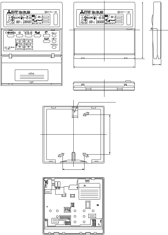
|
|
|
|
|
|
2. REMOTE CONTROLLER |
|
|
Unit : mm (inch) |
||
|
|
|
|
|
|
|
|
|
|
|
|
FILTER |
FILTER |
CHECK MODE |
CHECK MODE |
TEST RUN |
TEST RUN |
120
18
130
Rear side wiring arrangement opening.
83.5
46
CAUTION
SW18
SW17
14

6 |
|
|
WIRING DIAGRAM |
|
|
|
|
|
||
|
|
|
|
|
|
|
|
|
||
PLH-1.6KKHB·UK/PLH-2KKHB·UK/PLH-2.5KKHB·UK |
|
|
|
|
||||||
|
|
|
|
|
|
|
|
|
||
SYMBOL |
|
NAME |
SYMBOL |
NAME |
SYMBOL |
NAME |
|
|
||
|
|
|
|
|
|
|
||||
R.B |
|
REMOTE CONTROLLER BOARD |
CN2L<I.B> |
LOSSNAY CONNECTOR |
X3<I.B> |
VANE MOTOR RELAY |
||||
|
|
|
|
|
|
|
|
|||
SW17<R.B> |
|
ADDRESS SELECTOR |
CN51<I.B> |
CENTRALLY CONTROL CONNECTOR |
X4<I.B> |
FAN MOTOR RELAY |
|
|||
|
|
|
|
|
|
|
|
|
||
SW18<R.B> |
|
FUNCTION SELECTOR |
FAN2<I.B> |
EMERGENCY OPERATION CONNECTOR |
F1<I.B> |
FUSE (6.3A) |
|
|
||
|
|
|
|
|
|
|
||||
CN1<R.B> |
|
PROGRAM TIMER CONNECTOR |
F.C<I.B> |
FAN PHASE CONTROL |
LED1<I.B> |
DC 12V POWER LED |
||||
|
|
|
|
|
|
|
||||
CN2<R.B> |
|
REMOTE SWITCH CONNECTOR |
SW1<I.B> |
MODE SELECTOR |
LED2<I.B> |
DC 5V POWER LED |
||||
|
|
|
|
|
|
|
||||
MV |
|
VANE MOTOR |
SW2<I.B> |
ADDORESS SELECTOR |
CNP<I.B> |
DRAIN PUMP CONNECTOR |
||||
|
|
|
|
|
|
|
||||
LS |
|
LIMIT SWITCH |
SW3<I.B> |
EMERGENCY OPERATION SWITCH |
CN50<I.B> |
DRAIN SENSOR CONNECTOR |
||||
|
|
|
|
|
|
|
|
|
||
H2 |
|
DEW PREVENTION HEATER |
SW5, SW7<I.B> |
MODEL SELECTOR |
DP |
DRAIN PUMP |
|
|
||
|
|
|
|
|
|
|
|
|||
RT1 |
|
ROOM TEMP. THERMISTOR(0°C/15K ,25°C5.4K ) |
SW6<I.B> |
TWIN, TRIPLE SWITCH |
DS |
DRAIN SENSOR |
|
|||
|
|
|
|
|
|
|
|
|
||
RT2 |
|
INDOOR COIL THERMISTOR(0°C/15K ,25°C5.4K ) |
SWA<I.B> |
HIGH SEILING, NOISE SAVING SELECTOR |
H1 |
HEATER |
|
|
||
|
|
|
|
|
|
|
|
|||
T |
|
TRANSFORMER |
SWB<I.B> |
NUMBER OF AIR OUTLETS SELECTOR |
FS1,2 |
THERMAL FUSE |
|
|||
|
|
|
|
|
|
|
||||
MF |
|
INDOOR FAN MOTOR |
SWC<I.B> |
OPTION SELECTOR |
26H |
HEATER THERMAL SWITCH |
||||
|
|
|
|
|
|
|
||||
C1 |
|
FAN MOTOR CAPACITOR |
ZNR<I.B> |
VARISTOR |
88H |
HEATER CONNECTOR |
||||
|
|
|
|
|
|
|
||||
TB2~6 |
|
TERMINAL BLOCK |
X1<I.B> |
DRAIN PUMP/D.HEATER RELAY |
CNV<I.B> |
VANE MOTOR CONNECTOR |
||||
|
|
|
|
|
|
|
|
|
||
I.B |
|
INDOOR CONTROLLER BOARD |
|
|
|
|
|
|
||
|
|
|
|
|
|
|
|
|
|
SUPPLY |
|
|
|
|
|
|
|
|
|
|
|
|
|
|
|
|
|
|
|
POWER 50Hz |
||
|
|
|
|
|
|
|
|
L |
~(1PHASE) |
|
|
|
|
|
|
|
|
|
|
-240V |
|
|
|
|
|
|
|
|
|
N |
220 |
60Hz |
|
|
|
|
|
|
|
|
|
220V |
|
|
|
|
|
|
|
|
|
|
|
|
|
|
|
|
|
|
|
RED ORN YLW |
|
|
|
T |
|
|
|
|
|
|
|
|
|
|
|
|
|
YLW |
YLW |
BRN |
BRN |
|
RED BLU |
|
RED |
YLW |
|
|
|
|
|
||
|
|
|
|
|
|
|
|
|
|
|
|
|
|
RED |
BRN |
|
|
||||||||
|
|
|
|
5 |
|
|
|
|
|
|
1 |
3 |
1 3 |
|
1 |
3 |
1 3 |
|
|
14.2V AC |
11.1V AC |
|
|
|
|
|
MF |
C1 |
BLK |
|
|
|
|
|
|
|
|
|
4 3 |
2 1 |
|
|
|
||||||||
|
|
WHT |
3 |
FAN1 |
|
|
|
|
|
CNV |
CNP |
|
CND |
CNT |
|
|
LED2 |
|
|||||||
|
|
|
RED |
1 |
|
FAN |
|
|
|
|
|
VANE |
D.U.M. |
F1 |
POWER |
TRANS |
|
CN4T |
|
5V POWER |
|
||||
|
|
|
|
|
|
|
|
|
|
|
|
|
|
|
|
|
|
TRANS |
|
|
|||||
|
|
|
F.C |
|
X4 |
|
|
|
|
|
|
|
|
|
|
|
|
1 |
|
|
|
|
CN22 |
1 |
|
|
|
|
|
|
|
|
|
|
X3 |
|
X1 |
|
|
|
|
2 |
|
|
|
1 |
TO REMOCON |
2 |
|||
|
|
|
|
|
|
|
|
|
|
|
|
|
|
|
|
|
3 |
|
CN40 |
|
|
||||
|
|
|
|
|
|
|
|
|
|
|
|
|
|
|
|
|
|
|
|
2 |
|
1 |
|||
|
|
|
|
|
|
|
|
|
|
|
|
|
|
ZNR |
|
|
|
4 |
|
|
|||||
|
|
|
|
|
|
X4 |
SW7 |
SW3 SWC |
X3 |
X1 |
|
|
CN50 |
|
REMOCON |
CN30 |
|||||||||
|
|
|
|
1 |
3 5 |
|
|
|
|
5 |
|
POWER |
3 |
2 |
|||||||||||
|
|
|
|
|
|
Showing |
|
OP |
|
|
|
|
|
|
|
DRAIN |
|
|
|
4 |
OUTDOOR |
3 |
|||
|
|
|
|
FAN2 |
|
|
|
STD |
|
|
|
|
LED1 |
|
|
CN51 |
1 |
|
CN41 |
|
|
|
|
||
|
|
|
|
|
123 fig:1 |
12 |
|
|
|
|
|
|
|
|
|
1 |
|
1 |
|||||||
|
1 |
|
|
|
|
|
|
|
|
|
|
|
|
12V POWER |
CONTROLCENTRALLY 2 |
|
1 |
CN21 |
CN23 |
||||||
|
2 |
|
|
|
|
|
SW2 |
SW5 |
SW6 |
SW1 |
SWA |
SWB |
|
|
CN24 |
|
3 |
|
2 |
PIPE |
2 |
VANE |
2 |
||
|
|
|
|
|
ON |
|
|
|
|
|
|
|
|
||||||||||||
|
3 |
|
|
|
|
|
|
|
|
|
3 |
2 |
|
|
|
4 |
|
3 |
|
1 |
|
1 |
|||
|
|
|
|
|
|
|
|
|
|
2 |
3 |
|
|
HEATER |
|
|
CN20 |
CN2L |
|||||||
|
4 |
|
|
|
|
OFF |
|
|
|
|
|
1 |
4 |
|
|
|
|
|
5 |
|
4 |
2 |
2 |
||
DS |
|
|
|
|
|
123456 |
1234 |
1234 |
12345678910 |
|
|
|
|
|
|
|
|
INTAKE |
LOSSNAY |
||||||
|
|
|
|
|
|
|
|
|
|
|
|
|
|
|
|
|
|
|
|
|
|
|
|
|
|
RT1 |
|
|
|
|
|
|
|
|
|
|
|
|
|
|
|
|
|
|
|
|
|
|
|
|
|
RT2 |
2 |
|
|
|
|
|
|
|
|
|
|
|
|
|
|
|
|
|
|
|
|
|
|
|
|
1 |
|
|
|
|
|
|
|
|
|
|
|
|
|
|
|
|
|
|
|
|
|
|
|
|
|
|
|
|
|
|
|
|
|
|
|
|
|
|
|
|
|
|
|
|
|
|
|
|
|
|
|
|
|
*PLH-1.6,2,2.5KKHB(with heater) |
|
|
|
|
|
|
|
|
|
|
|
|
|
|
|
|
|
||||||
|
|
|
|
|
|
|
|
|
|
|
|
|
|
|
HEATER |
|
|
|
|
|
|
|
|
|
|
|
|
|
|
|
RED 3 |
88H 5 |
RED FS1 |
FS2 |
|
H1 |
|
|
CN24 |
|
|
|
|
|
|
|
|
|
|
||
|
|
|
|
|
|
|
|
|
|
|
|
|
|
|
|
|
|
|
|||||||
|
POWER SUPPLY |
|
TB2 |
BLU |
|
1 BLU |
|
|
|
|
|
|
|
|
|
|
|
|
|
|
|
|
|||
|
|
L |
|
|
|
|
3 |
|
|
|
|
|
|
|
YLW 6 |
1 |
|
|
YLW |
26H |
|
|
|
||
|
~(1PHASE) |
|
N |
|
|
|
|
|
|
|
|
|
|
|
|
|
1 |
|
|
|
|||||
|
220-240V |
|
|
|
|
|
|
|
|
|
|
|
|
|
|
|
88H |
|
|
|
|
|
|
||
|
|
|
|
|
|
|
|
|
|
|
|
|
|
|
YLW |
|
|
|
2 YLW |
|
|
|
|
||
|
50Hz |
|
|
|
|
|
|
|
|
|
|
|
|
|
|
|
|
|
|
|
|
|
|||
GRN/YLW
TB2
|
|
1 |
18 |
|
|
|
SW |
OFF |
|
|
. |
2 |
|
ON |
.B |
|
|
|
|
R |
|
|
|
|
|
2 |
|
7 |
LU |
|
B |
1 |
|
LU |
B 6 |
|
|
GRILL |
|
|
|
LS |
MV |
|
|
H2 |
5 |
10 |
|
N |
|
N R |
||
|
R B |
|
N |
B |
|
|
|
|
BR |
|
|
DP |
|
|
N |
|
|
BR |
|
|
DC12V |
|
|
CN2 |
|
|
|
TB6 |
|
|
|
|
|||
|
|
1 |
2 |
|
|
|
|
|
SW |
|
ON |
|
||
|
|
|
|
|
|
3 |
|
|
|
17 |
OFF |
|
||
|
|
|
|
|
|
|
|
|
|
|
|
|||
|
WIRES |
|
|
|
|
CN |
|
|
|
|
|
|
||
|
|
|
|
|
|
|
|
1 |
|
5 |
|
|
|
|
|
|
|
|
|
|
|
|
3 |
4 |
|
|
|
|
|
|
|
|
|
|
|
|
2 |
|
|
|
|
|
||
|
TRNSMISSION |
1 |
|
|
|
|
|
|
||||||
|
|
|
|
|
|
|
|
|||||||
|
|
|
|
|
|
|
|
|
|
|
|
OUTDOOR |
||
|
|
|
|
|
|
|
|
|
|
|
|
UNIT |
|
|
|
|
|
|
|
|
|
|
|
|
|
DC12V |
|
1 |
|
|
1 |
|
|
|
|
|
|
|
|
|
|
2 |
||
|
|
|
|
|
|
|
|
|
|
WIRES |
|
|
||
BLU |
2 |
|
|
|
|
|
TRNSMISSION |
|
|
3 |
||||
|
|
|
|
|
|
|
|
|||||||
BLU |
|
|
|
|
|
|
|
|
|
|||||
|
|
|
|
|
|
|
|
|
|
|
|
|
|
|
|
|
|
1 |
|
|
|
|
|
|
|
|
|
TB3 |
|
|
|
BRN |
|
2 |
|
|
|
|
|
|
|
|
|
1 |
|
|
|
|
|
|
|
|
|
|
BG79Y408H0 |
||||
|
|
YLW |
|
|
|
|
|
|
||||||
|
|
ORN |
3 |
|
|
|
|
|
|
|
|
|
|
|
|
|
|
|
|
|
|
|
|
|
|
|
|
|
|
|
|
|
|
|
TB4 |
|
|
|
|
|
|
|
||
fig:1
MODELS |
1.6KK |
2KK |
2.5KK |
SW7 |
ON |
ON |
ON |
OFF |
OFF |
OFF |
|
|
1 2 3 |
1 2 3 |
1 2 3 |
NOTES :
1. Since the indoor transformer (T)is connected with 240Vpower. If 220, 230v power is used. change the wiring connection showing fig: w2
|
|
|
|
|
|
|
240V |
YELLOW |
|
|
fig:w2 |
|
|
|
|
|
|
|
|
|
|
|
|
|
|
230V |
ORANGE |
||
|
|
|
|
|
|
|
|||
When power supply is |
230V |
|
|
|
220V |
RED |
|
||
|
|
|
|
|
|||||
220V |
|
|
|
|
|
|
|
||
2.Since the outdoor side electric wiring may change be sure to check the outdoor unit electric wiring for servicing.
3.Indoor and outdoor connecting wires are made with polarities. make wiring matching terminal numbers.
4.Symbols used in wiring diagram above are. / : Terminal block, 

 : Connector.
5.Emergency operation
If remote controller or microcomputer fails but there is no other truble,. emergency operation is possible by setting dip switch (SW3<I.B>) on the indoor controller board.
[Check items]
(1)Make sure that no other trouble exists the outdoor unit. Trouble with the outdoor unit prevents emergency operation.
(If any trouble exists the outdoor unit error code “P8”will be displayed on the remote controller and the trouble position will be shown on the outdoor controller board LED. See electric wiring diagram of the outdoor unit for details.)
(2)Make sure that there is no trouble with the indoor fan.
Emergency operation will be continuous run with the power ON/OFF (ON/OFF with the remote controller is not possible). [Emergency operation procedure]
(1)Switch the fan connector on the indoor controller board from FAN 1 to FAN 2.
(2)Set the dip switch (SW3<I.B>) on the indoor controller board to 1 on and 2 off for cooling and 1 - 2 on for heating. (3)Turn on the outdoor unit side circuit breaker, then the indoor unit side circuit breaker.
(4)During emergency operation indoor fan runs at High speed but auto-vane does not work.
(5)Thermostat will not function. Cold air blows out for defrosting during heating thus do not operate defrosting for a long time. (6)Emergency cooling should be limited to 10 hours maximum. (the indoor unit heat exchanger may freeze).
(7)After every operation, switch the fan connector to FAN1, and set all dip switches (SW3<I.B>) to OFF.
NOTE: If the drain water lift up mechanism is identified to be defective with the microcomputer doctor during cooling, do not use emergency operation (it causes drain overflow)
15
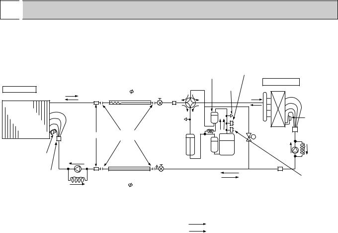
7 
 REFRIGERANT SYSTEM DIAGRAM
PLH-1.6KKHB·UK/PUH-1.6VKA3·UK PLH-2KKHB·UK/PUH-2VKA2·UK PLH-2.5KKHB·UK/PUH-2.5VKA2·UK
Unit : mm
 Flow of refrigerant (cooling)
 Flow of refrigerant (heating)
High pressure
control switch
Oil separator
|
|
Refrigerant pipe |
4-way valve |
Service |
Outdoor unit |
|
|
Indoor unit |
|
(option) |
|
port |
Outdoor heat exchanger |
|
|
|
15.88mm( |
5/8") |
Ball valve |
|
|||
|
|
|
|
|
|||
|
|
(with heat insulator) |
Strainer |
|
|
|
|
|
|
|
|
|
|
|
|
|
|
Flexible tube |
|
|
|
|
|
Indoor |
|
|
|
Service |
|
|
Outdoor coil |
heat |
|
|
|
port |
|
|
|
|
|
|
|
|
thermistor |
||
exchanger |
|
|
|
|
|
|
|
|
|
|
|
|
|
(TH) |
|
|
|
|
|
|
|
|
|
|
Strainer |
Flared |
|
|
|
Bypass |
|
|
connection |
|
|
|
|||
|
|
|
|
valve |
w |
||
|
|
|
|
|
|
||
|
|
|
|
Accumulator |
|
|
|
|
|
|
|
|
Restrictor |
Capillary |
|
Indoor coil |
Restrictor |
|
|
|
|
valve |
tube |
|
|
|
Compressor |
|
|
||
thermistor |
valve |
|
|
|
|
|
|
(RT2) |
|
|
|
|
|
|
|
Distributor |
|
Refrigerant pipe |
Ball valve |
|
with |
|
|||
|
(option) |
|
(with service port) |
|
strainer |
|
|
||
Capillary |
9.52mm( |
3.8") |
|
|
|
|
|||
|
(with heat insulator) |
|
||
|
tube |
|
||
|
|
|
|
|
PLH-1.6 (O.D.3.2 I.D.1.6 –R630) PLH-2.5 (O.D.3.2 I.D.1.8 –R430) PLH-2 (O.D.3.2 I.D.1.8 –R630)
Strainer
wPLH-1.6 (O.D.3.2 I.D.1.8 –R400) PLH-2 (O.D.4.0 I.D.2.0 –R430) PLH-2.5 (O.D.4.2 I.D.2.4 –R1550)
High pressure protect switch
Refrigerant flow in cooling |
R.V.coil |
|
Heating ON |
||
Refrigerant flow in heating |
||
Cooling OFF |
||
|
16
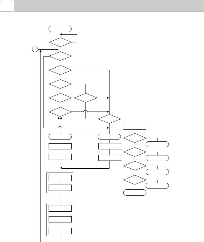
8 
 OPERATION FLOW-CHART
MAIN OPERATION
START |
|
Power circuit |
NO |
|
|
breaker |
|
1 YES
YES
YES Check SW |
|
|
|
|
|
|
|
|
|||||
|
|
ON twice |
|
|
|
|
|
|
|
|
|||
|
|
|
NO |
w1 |
|
|
|
|
|
||||
|
|
|
|
|
|
|
|
|
|
|
|||
|
|
Operation |
SW |
YES |
|
|
|
|
|
||||
|
|
|
|
|
|
|
|
|
|
||||
|
|
|
ON |
|
|
|
|
|
|
|
|
||
|
|
|
NO |
|
|
|
|
|
|
|
|
||
|
|
“OFF” timer |
YES |
|
|
|
|
|
|||||
|
|
|
|
|
|
|
|
|
|
||||
|
|
|
NO |
|
|
|
|
|
|
|
|
||
NO |
Set |
time |
NO |
|
|||||||||
|
|
“ON” timer |
|
|
|
|
|
|
|
|
|||
|
|
complete |
|
|
|
|
|
||||||
|
|
|
|
|
|
|
|
|
|
|
|||
|
|
|
YES |
|
YES |
|
|
|
|
|
|||
|
|
|
|
|
|
|
|
|
|
|
|||
|
|
Set time |
YES |
|
|
|
|
|
|||||
|
|
complete |
|
|
|
|
|
w2 |
|
||||
|
|
|
|
|
NO |
|
|
|
|
|
|
||
|
|
|
|
|
|
|
|
Trouble |
NO |
|
|||
|
|
|
|
|
|
|
|
|
|
|
|
||
|
|
|
|
|
|
|
|
|
|
|
|
||
|
|
|
|
|
|
|
|
|
|
|
|
|
|
|
YES |
Remote controller |
|
|
|
|
operation display |
|
|
STOP |
Trouble STOP |
Operating mode |
YES |
|
|
||||
|
|
(COOL) |
|
|
PROTECTION DEVICE |
PROTECTION DEVICE |
NO |
COOL operation |
|
SELF HOLD RELEASE |
SELF HOLD |
|
YES |
|
|
|
Operating mode |
||
|
w3 |
|
||
Remote controller |
(DRY) |
|
||
Remote controller |
|
|
||
indicator lamp OFF |
|
DRY operation |
||
trouble display |
NO |
|||
|
|
|||
|
|
Operating mode |
YES |
|
|
|
|
||
|
|
(HEAT) |
|
|
Indoor side |
|
NO |
HEAT operation |
|
|
w4 |
|||
|
|
|||
|
w6 |
YES |
||
Fan STOP |
|
|||
|
Operating mode |
|||
|
|
(FAN) |
w7 |
|
Auxiliary heater OFF |
|
NO |
FAN operation |
|
|
|
|||
|
|
|
||
|
|
Auto COOL/HEAT |
|
|
|
|
operation |
|
Outdoor side
w5
Compressor OFF
Fan STOP
Four-way valve OFF
w1 In addition, the centralized control and remote control can be operated. w2 The modes which indicate the sources of trouble are listed below.
●EO-Signal transmitting/receiving error
●P1-Room temperature thermistor malfunction
●P2-Indoor coil thermistor malfunction
●P4-Drain sensor malfunction
●P5-Drain overflow
●P6-Coil frost/overheat protection
●P7-System error
●P8-Outdoor unit trouble
w3 The CHECK swich will show if an error has occurred in the past. w4 Fan runs on low speed for 1 minute in order to remove overheat air.
w5 The 3-minute (6 minutes … heating mode) time-delay functions after compressor stops. w6 FAN or AUTO mode is selected by the indoor dipswitch setting.
w7 In FAN mode, fan speed and vane operation depend on the remote controller setting. (Compressor is OFF.)
17
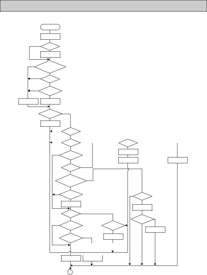
COOLING OPERATION
COOL operation
Four-way valve/OFF
NO |
|
Initial |
|
|
|
|
COOLING |
|
|
|
w8 |
|
YES |
|
|
Vane initial |
|
||
|
|
setting |
|
|
NO |
|
Vane |
|
|
55 deg downward angle |
|
|||
|
70 deg downward angle |
|
||
NO |
|
|
YES |
|
|
Fan speed |
|
|
|
|
|
|
|
|
|
|
LOW |
|
|
|
|
|
YES |
|
NO |
Downward discharge |
|
||
|
|
|||
|
|
1 hour |
|
|
|
|
|
YES |
|
Vane setting notch |
Vane horizontal |
|
||
|
airflow |
|
|
|
|
|
|
|
|
|
w9 |
Compressor |
NO |
YES |
|
|
|
||
|
|
thermostat |
|
|
|
|
ON |
NO |
|
|
|
|
|
|
|
Allowance |
|
||
|
|
cancel |
|
|
NO YES |
3-minute |
|
|
|
time delay |
|
|
|
NO |
|
|
YES |
6-minute |
Allowance |
YES |
|
time delay |
period |
|
|
|
|
|
NO |
|
|
NO |
|
|
|
|
|
6 minute |
|
|
|
|
|
|
|
|
|
|
NO |
3-minute |
|
|
time delay |
|
|
|
compressor operation |
|
|
|
|
|
|
YES |
|
|
Allowance set |
|
Coil frost protection |
|
|
|
|
|
|
|
|
w10 |
YES |
|
|
|
|
|
Coil frost |
|
|
|
|
|
|
prevention |
|
|
|
|
|
|
NO |
|
|
|
|
|
w11 |
|
NO |
|
|
|
|
|
Cooling area |
|
|
|
|
|
|
|
|
|
|
|
|
|
YES |
|
|
|
|
|
NO |
10-minute |
|
|
NO |
|
|
|
compressor operation |
|
|
1 min continue |
|
|
|
|
|
|
|
|
|
|
YES |
|
|
|
YES |
|
|
Allowance cancel |
|
|
|
|
|
|
|
|
|
FAN speed |
|
|
|
|
|
|
|
|
|
|
|
|
|
|
LOW |
|
|
Coil frost |
YES |
|
|
|
|
|
protection |
|
|
|
|
YES |
|
NO |
|
|
|
FAN speed |
|
|
|
|
|
LOW 5 min |
|
|
NO |
16-minute |
|
Indoor coil |
NO |
elapse |
|
|
tempreature is |
|
NO |
|
||
|
compressor operation |
|
|
|
||
|
|
|
10 C or higher |
|
|
Outdoor unit |
|
YES |
|
YES |
|
|
trouble |
|
|
|
|
|
||
|
Indoor pipe |
YES |
3-minute |
|
|
|
|
temperature is |
|
time delay |
|
|
|
|
1 C or lower |
|
|
|
|
|
NO |
Coil frost |
|
Coil frost |
||
|
prevention |
|
prevention release |
||
|
|
|
|
|
|
|
|
|
|
|
|
Compressor ON Compressor OFF
1
w8 When operation stops or changes to cooling or dry mode, the auto vane tums to a horizontal angle. If operation changes during auto vane SWING, the auto vane will continue to swing.
w9 When operating TEST RUN, the thermostat will be continuously ON.
w10 After 3 minute compressor operation, if the indoor coil thermistor reads -15°C or below for 3 minutes, the compressor will stop for 6 minutes.
w11 Cooling area : Indoor coil temperature is more than 5 degrees above the room temperature. Heating area : Indoor coil temperature is more than 5 degrees below the room temperature. FAN area : Indoor coil temperature is within 5 degrees either way of the room temperature.
18
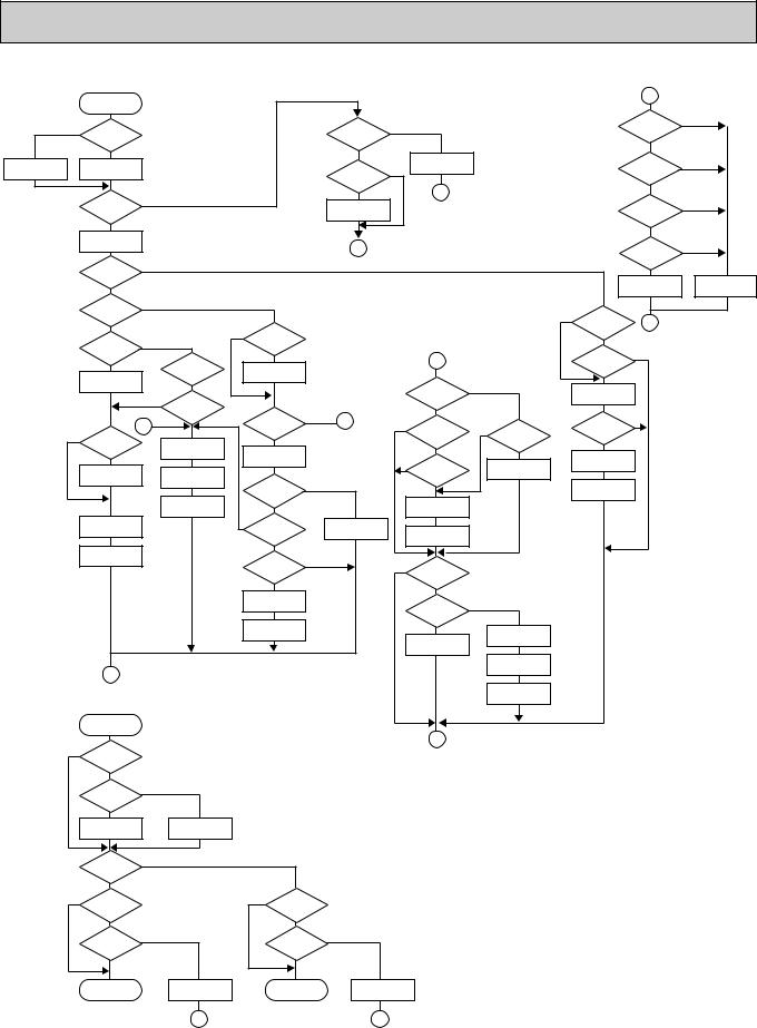
HEATING OPERATION |
|
|
|
|
|
|
|
|
|
|
|
|
|||
|
Heat operation |
|
|
|
|
|
|
|
|
|
|
|
|
A |
|
|
|
|
|
|
|
|
|
|
|
|
|
|
|
|
|
|
w15 |
|
|
|
|
w11 |
YES |
|
|
|
|
|
PLH-KKHB |
NO |
|
NO |
|
|
|
|
|
|
|
|
|
|
|||||
Initial |
|
|
|
|
|
Heating area |
|
|
|
|
|
Type |
|
||
|
HEATING |
|
|
|
|
|
|
|
|
|
|
|
|
|
|
|
|
|
|
|
|
|
|
|
|
|
|
|
|
|
|
|
YES |
|
|
|
|
|
NO |
|
|
|
|
|
|
NO |
|
|
|
|
|
|
|
|
Defrost release |
|
|
|
|
3-minute |
NO |
||
Vane setting notch |
Vane initial setting |
|
|
|
|
|
|
|
|
|
|
|
|||
|
|
|
|
|
Defrost |
NO |
|
|
|
|
|
Auxiliary heater |
|
||
|
|
|
|
|
|
|
30 min. elapse |
|
|
|
|
|
|
OFF |
|
|
|
YES |
|
|
|
|
YES |
|
2 |
|
|
|
|
NO |
|
|
|
|
|
|
|
|
|
|
|
|
|
|
|
||
|
Defrosting |
|
|
|
|
|
|
|
|
|
|
|
Indoor coil |
NO |
|
|
|
|
|
|
|
Outdoor unit trouble |
|
|
|
|
|
|
|||
|
|
|
|
|
|
|
|
|
|
|
|
thermstor is 60 C |
|
||
|
|
|
|
|
|
|
|
|
|
|
|
|
|
||
|
|
|
|
|
|
|
|
|
|
|
|
|
|
|
|
|
NO |
|
|
|
|
|
|
|
|
|
|
|
|
or higher |
|
|
|
|
|
|
|
|
|
|
|
|
|
|
|
|
|
|
Four-way valve ON |
|
|
|
|
|
1 |
|
|
|
|
|
|
|
NO |
|
|
|
|
|
|
|
|
|
|
|
|
|
FAN speed |
||
|
|
|
|
|
|
|
|
|
|
|
|
|
|
|
|
|
|
YES |
|
|
|
|
|
|
|
|
|
|
|
Low notti |
|
|
Hor adjust |
|
|
|
|
|
|
|
|
|
|
|
YES |
|
|
|
|
|
|
|
|
|
|
|
|
|
|
|
|
||
|
in process |
|
|
|
|
|
|
|
|
|
|
|
|
|
|
|
|
|
|
|
|
|
|
|
|
|
|
|
|
|
|
|
NO |
|
|
|
|
|
|
|
|
|
|
|
Airflow 10% up |
FAN setting notch |
|
|
|
|
|
|
|
|
|
|
|
|
|
|
|
|
|
|
Compressor ON |
YES |
|
|
|
|
|
|
|
|
|
|
|
|
|
|
|
|
|
|
|
|
|
|
|
|
YES |
Indoor piping |
|
|
|
|
|
|
|
|
|
|
|
|
|
|
|
B |
|
||
|
NO |
|
|
|
|
|
|
|
|
|
|
|
35 C or higher |
|
|
|
|
NO |
|
10-minute |
|
|
|
|
|
|
|
|
|
||
|
|
|
|
|
|
|
|
|
|
|
|
|
|||
|
|
|
|
|
|
|
|
|
|
|
|
|
|
||
|
Compressor |
YES |
|
|
compressor |
|
|
|
|
|
|
|
NO |
|
|
w9 |
|
|
operation |
|
|
|
|
|
|
|
|
|
|||
thermostat ON |
|
|
|
|
|
|
|
|
|
|
|
NO |
|
||
|
|
|
|
YES |
|
|
|
|
|
|
|
HOT adjust |
|
||
|
|
|
|
|
|
|
|
B |
|
|
|
|
|||
|
|
|
3 min.restart |
|
|
|
|
|
|
|
|
|
|||
|
|
|
|
|
|
|
|
|
|
|
6 min. elapse |
|
|
||
|
|
|
|
|
|
|
|
|
|
|
|
|
|
||
|
|
|
prevention |
Allowance cancel |
|
|
|
|
|
|
|
YES |
|
|
|
|
Allowance cancel |
|
|
|
|
|
|
|
|
YES |
|
|
|
|
|
|
|
NO |
|
|
|
|
|
Indoor piping |
|
|
|
|
|
||
|
|
|
|
|
|
|
|
|
|
FAN SPEED |
|
|
|||
|
|
YES |
6 min. restart |
|
|
|
|
|
55 C or lower |
|
|
|
Low |
|
|
|
|
|
|
|
|
|
|
|
|
|
|
|
|
|
|
|
|
|
prevention |
|
Heating |
YES |
|
|
NO |
|
|
|
|
NO |
|
|
|
|
NO |
|
A |
|
|
|
|
|
FAN SPEED |
|
|||
|
|
2 |
|
|
NO |
|
|
|
|
|
|
||||
|
|
|
|
area |
|
|
Auxiliary heater |
NO |
Auxiliary heater |
|
Low 2 min. |
|
|
||
NO |
Indoor piping |
|
|
|
|
|
|
|
ON |
|
|
elapse |
|
|
|
|
|
|
NO |
|
|
|
|
thermostat ON |
|
|
|
||||
|
-15 C or lower |
|
Hot adjust start |
|
|
|
|
|
YES |
|
YES |
|
YES |
|
|
|
YES |
|
|
FAN STOP |
|
|
|
|
|
FAN SPEED |
|
|
|||
|
|
|
|
|
NO |
|
|
|
|
|
|
||||
|
|
|
|
|
|
|
|
Indoor piping |
|
Auxiliary heater ON |
|
setting nitch |
|
|
|
|
Outdoor unit |
|
|
|
|
|
|
|
|
|
|
|
|||
|
|
FAN SPEED very low |
w11 |
|
|
|
60 C or higher |
|
|
|
|
|
|||
|
trouble |
|
YES |
|
|
|
|
|
|
|
|
|
|||
|
|
|
|
|
Airflow area |
|
|
YES |
|
|
|
Hot adjust |
|
|
|
|
|
|
|
|
20 min.elaspe |
|
|
|
|
|
|
release |
|
|
|
|
|
|
|
|
|
|
|
|
|
|
|
|
|
||
|
|
|
Compressor ON |
|
|
|
|
|
Auxiliary heater OFF |
|
|
|
|
|
|
|
FAN SPEED |
|
YES |
w10 |
|
|
|
|
|
|
|
|
|
||
|
|
Airflow area |
|
Outdoor unit |
|
|
|
|
|
|
|
|
|||
|
|
|
|
|
|
|
|
|
|
|
|
|
|||
|
Very low airflow |
|
|
|
Heating area |
|
trouble |
|
Overheat remote |
|
|
|
|
|
|
|
|
|
|
|
|
|
|
|
START |
|
|
|
|
|
|
|
Compressor OFF |
|
|
w11 |
NO |
|
|
|
|
|
|
|
|
|
|
|
|
|
Airflow area |
NO |
|
|
|
|
|
|
|
|
|
||
|
|
|
|
|
|
NO |
Indoor unit |
|
|
|
|
|
|
||
|
|
|
|
|
Cooling area |
|
|
|
|
|
|
|
|
||
|
|
|
|
|
|
|
|
|
|
|
|
|
|
||
|
|
|
|
|
|
|
|
70 C or higher |
|
|
|
|
|
|
|
|
|
|
|
|
|
|
|
|
|
|
|
|
|
|
|
|
|
|
|
|
YES |
|
|
|
YES |
|
|
|
|
|
|
|
|
|
|
Defrost operation |
|
|
|
|
|
|
|
|
|
||
|
|
|
|
|
|
|
|
|
|
|
|
|
|
||
|
|
|
|
|
START |
|
|
|
Allowance |
NO |
|
|
|
|
|
|
|
|
|
|
|
|
|
|
period |
|
|
|
|
|
|
|
|
|
|
Four-way valve |
|
|
|
YES |
|
6-minute restart |
|
|
|
|
|
|
|
|
|
|
OFF |
|
|
|
|
|
|
|
|
||
|
|
|
|
|
|
|
|
|
Overload protect |
|
prevention |
|
|
|
|
|
|
|
|
|
|
|
|
|
|
|
|
|
|
|
|
|
|
|
|
|
|
|
|
|
|
|
Allowance set |
|
|
|
|
|
1 |
|
|
|
|
|
|
|
|
|
|
|
|
|
|
|
|
|
|
|
|
|
|
|
|
|
Compressor OFF |
|
|
|
|
|
AUTOMATIC COOLING/HEATING OPERATION |
|
|
|
|
|
|
|
|
|
|||||
|
Auto COOL/HEAT |
|
|
|
|
|
|
|
|
|
|
|
|
|
|
|
operation |
|
|
|
|
|
|
|
|
|
|
|
|
|
|
|
w16 |
|
|
|
|
|
|
1 |
|
|
|
|
|
|
|
NO |
|
|
|
|
|
|
|
|
|
|
|
|
|
||
Initial mode |
|
|
|
|
|
|
|
|
|
|
|
|
|
|
|
|
|
|
|
|
|
|
|
|
|
|
|
|
|
|
|
|
YES |
|
|
|
|
|
|
|
|
|
|
|
|
|
|
|
w17 |
NO |
|
|
|
|
|
|
|
|
|
|
|
|
|
|
> |
|
|
|
|
|
|
|
|
|
|
|
|
|
|
|
T1 =T0 |
|
|
|
|
|
|
|
|
|
|
|
|
|
|
|
YES |
|
|
|
|
|
|
|
|
|
|
|
|
|
|
|
COOL mode |
|
HEAT mode |
|
|
|
|
|
|
|
|
|
|
|
|
|
COOL mode |
NO |
|
|
|
|
|
|
|
|
|
|
|
|
|
|
|
|
|
|
|
|
|
|
|
|
|
|
|
|
|
|
YES |
|
|
|
|
|
|
|
|
|
|
|
|
|
|
NO |
T1 < (T0 - 2) |
|
|
NO |
|
|
|
|
|
|
|
|
|
|
|
|
|
|
|
T1>(T0 + 2) |
|
|
|
|
|
|
|
|
|
||
|
YES |
|
|
|
|
YES |
|
|
|
|
|
|
|
|
|
|
After 15min. |
YES |
|
|
After 15min. |
YES |
|
|
|
|
|
|
|
|
|
|
|
|
|
T1>(T0 + 2) |
|
|
|
|
|
|
|
|
|
||
|
T1<(T0-2) |
|
|
|
|
|
|
|
|
|
|
|
|
||
|
|
|
|
|
|
|
|
|
|
|
|
|
|
|
|
|
NO |
|
|
|
NO |
|
|
|
|
|
|
|
|
|
|
|
|
|
|
|
|
|
|
|
|
|
|
|
|
|
|
|
COOL operation |
|
HEAT operation |
|
HEAT operation |
Cool mode |
|
|
|
|
|
|
|
||
|
|
|
set |
|
|
|
|
|
|
|
|
||||
|
|
|
|
|
|
|
|
|
|
|
|
|
|
|
|
|
|
|
1 |
|
|
|
1 |
|
|
|
|
|
|
|
|
w15 ( i ) Until Low airflow is set while hot adjustment (ii)While defrosting (FAN STOP)
(iii)When thermostat is OFF
In the case of( i ), (ii) and (iii) above, airflow is horizontal regardless the VANE setting. w16 When AUTO operation is started, COOL or HEAT mode is selected automatically.
w17 T1 : Room temperature. To : Set temperature
19
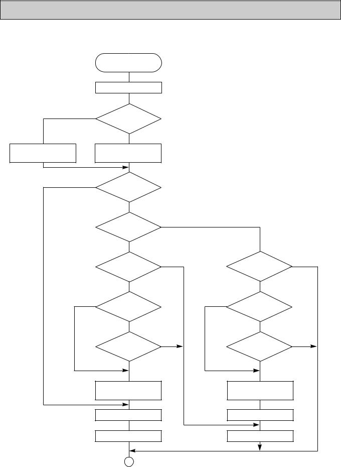
DRY OPERATION
DRY operation
Four-way valve / OFF
NO |
Initial dry |
|
|
operation |
|
|
YES |
w8 |
Vane |
Vane initial setting |
|
setting notch |
||
|
YES |
w12 |
|
|
|
|
Room tempereature is |
|
|
|
|
|
|
|
|
|
|
|
|
18°C or lower |
|
|
|
|
|
NO |
|
|
|
|
|
During |
NO |
|
|
|
|
compressor ON |
|
|
|
|
|
YES |
|
|
|
|
|
3-minute |
NO |
|
|
YES |
|
compressor |
|
|
delay |
|
|
operation |
|
|
|
|
|
|
|
|
|
|
|
YES |
|
|
NO |
|
NO |
w9 |
|
YES |
Compressor & |
w9 |
|
|
|
|||
|
|
|
|
thermostat |
|
|
|
|
|
ON |
|
|
YES |
|
|
NO |
|
|
Compressor ON |
NO |
|
|
NO |
|
|
|
|
|
|
|
time completes |
|
|
|
|
|
YES |
|
|
YES |
w13 |
|
|
|
|
|
|
|
10-minute compressor |
|
|
|
|
|
OFF timer start |
|
|
|
|
|
Compressor OFF |
|
|
|
|
|
w14 |
|
|
|
w14 |
|
Fan STOP |
|
|
|
|
|
1 |
|
|
|
|
w8—9 Refer to page 26~27.
w12 When room temperature is 18°C or below, the compressor cannot operate.
When room temperature rises over 18°C, the compressor starts after a 3-minute time delay. w13 Compressor ON time is decided by room temperature. Refer to page 26~27 .
w14 In dry operation, compressor ON makes the fan speed LOW and compressor OFF stops the fan. It is not possible to set the fan speed with the remote controller
20
9 
 MICROPROCESSOR CONTROL
1.OUTLINE OF MICROPROCESSOR CONTROL
INPUT to remote controller
●OFF-ON switching.
●COOL/DRY-AUTO-HEAT selector switching.
●Thermostat setting.
●TIMER mode selector-switching and Timer setting.
●HIGH-LOW fan speed switching.
●AUTO Vane selector (AIR DISCHARGE) switching.
●TEST RUN switching.
●CHECK mode switching.
(Self diagnostic trouble shooting)
Indoor unit
Remote controller board |
OUTPUT to remote controller |
|
|
● Processes and transmits |
Remote controller |
orders. |
|
|
● LCD indicator |
|
FILTER |
|
CHECK MODE |
|
TEST RUN |

 240KA
240KA
|
Non-polar, two-wire cable |
|
12VDC |
maxinmum length 500 meters |
|
Signal |
||
|
INPUT from indoor unit
●Room temperature thermistor (RT1)
●Indoor coil thermistor (RT2)
●Drain sensor
OUTPUT to indoor unit
Indoor controller board
●Receives orders from remote controller and temperature data from indoor unit.
●Processes orders and data.
●Controls indoor and outdoor operation.
●Self diagnostic function.
wSystem control operation.
wEmergency operation.
wSet by dipswitch on indoor controller board.
● Transmits the power to remote controller.
1 2 3
● Autovane’s angle setting. |
|
|
|
● Booster heater ON-OFF Control. |
|
unit |
|
● Drain pump : ON-OFF. |
|
||
● Emergency stop. |
Polar three-wire cable |
outdoor |
|
|
|||
|
|
||
Independent Control of |
Outdoor unit |
to |
|
Outdoor Unit |
|||
|
|||
12VDC |
OUTPUT |
||
● Compressor |
|||
|
|
||
protectiondevice working |
|
|
|
● Defrosting |
|
|
|
START-STOP |
|
|
|
● Fan speed control. |
1 |
|
|
● Crankcase heater control |
2 |
|
|
ON-OFF. |
3 |
|
|
● Self diagnostic function |
|
|
●Compressor and outdoor fan : ONOFF
●Operation mode change :COOLHEAT.
21
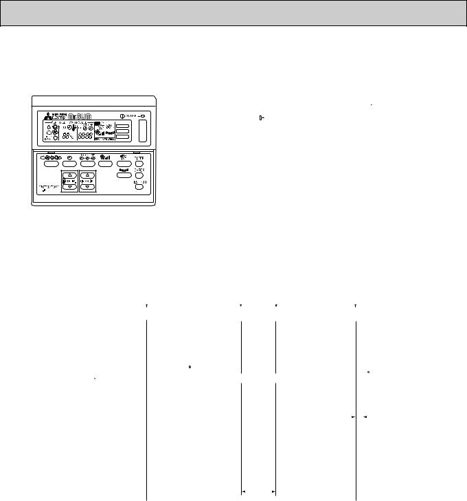
2. INDOOR UNIT CONTROL
2-1COOL operation
FILTER
CHECK MODE
TEST RUN

 240KA
240KA
<How to operate>
1 Press POWER ON/OFF button.
2 Press the 


 button to display “

 ”
”
3 Press the  TEMP button to set the desired temperature.
NOTE: Set temperature changes 1°C when the  or
or  button is pressed one time.
Cooling 19 to 30°C
<COOL operation time chart>
|
|
|
Operation starts by |
|
|
Room temperature |
|
Room temperature |
|
Operation stops by |
|||||||||||
|
|
|
P O W E R b u t t o n |
|
|
becomes equal to |
|
rises above set |
|
P O W E R b u t t o n |
|||||||||||
|
|
|
ON. |
|
|
set temperature. |
|
temperature. |
|
OFF. |
|||||||||||
|
|
|
|
|
|
|
|
|
|
|
|
|
|
|
|
|
|
|
|
|
|
Thermostat |
ON |
|
|
|
|
|
|
|
|
|
|
|
|
|
|
|
|
|
|
|
|
|
|
|
|
|
|
|
|
|
|
|
|
|
|
|
|
|
|
|
|||
OFF |
|
|
|
|
|
|
|
|
|
|
|
|
|
|
|
|
|
|
|
||
|
|
|
LOW or HIGH |
|
|
|
LOW or HIGH |
|
|
|
|
|
|
||||||||
|
ON |
|
|
|
|
|
|
|
|
|
|
|
|||||||||
Indoor fan |
OFF |
|
|
Initally 30 |
degrees |
|
|
|
|
|
|
|
|
|
|
|
|||||
|
|
|
|
|
|
|
30 |
|
|
||||||||||||
|
|
|
|
|
|
|
|
|
|
|
|
||||||||||
|
30 |
|
|
|
|
|
(Changeable by remote controller setting) |
|
|
||||||||||||
|
|
|
|
|
|
|
|
discharge |
|||||||||||||
|
|
|
|
|
|
|
|
|
|
|
|
|
|
|
|
|
|||||
Auto vane |
air flow |
|
|
|
|
|
|
|
|
|
|
|
|
|
|
|
position |
||||
position |
|
|
|
|
|
|
|
|
|
|
|
|
|
|
|
|
|
|
|
||
|
|
|
|
|
|
|
|
|
|
|
|
|
|
|
|
|
3 minutes |
||||
Drain pump |
ON |
|
|
|
|
|
|
|
|
|
|
|
|
|
|
|
|
||||
|
|
|
|
|
|
|
|
|
|
|
|
|
|
|
|
||||||
|
|
|
|
|
|
|
|
|
|
|
|
|
|
|
|
|
|
|
|||
|
|
|
|
|
|
|
|
|
|
|
|
|
|
|
|
|
|
|
|||
|
|
|
|
|
|
|
|
|
|
|
|
|
|
|
|
|
|
|
|||
|
|
|
|
|
|
|
|
|
|
|
|
|
|
|
|
|
|
|
|
|
|
|
OFF |
|
|
|
|
|
|
|
|
|
|
|
|
|
|
|
|
|
|
|
|
|
|
|
|
|
|
|
|
|
|
|
|
|
|
|
|
|
|
|
|
||
|
ON |
|
|
|
|
|
|
|
|
|
|
|
|
|
|
|
|
|
|
|
|
Booster heater |
OFF |
|
|
|
OFF |
|
|
|
|
|
|
|
|
|
|
|
|||||
|
|
|
|
|
|
|
|
|
|
|
|
|
|
|
|
|
|
|
|||
|
|
|
|
|
|
|
|
|
|
|
|
|
|
|
|
|
|
|
|||
Compressor |
ON |
|
|
|
|
|
|
|
|
|
|
|
|
|
|
|
|
|
|
|
|
|
|
|
|
|
|
|
|
|
|
|
|
|
|
|
|
|
|
|
|||
OFF |
|
|
|
|
|
|
|
|
|
|
|
|
|
|
|
|
|
|
|
||
|
|
|
|
|
|
|
|
|
|
|
|
|
|
|
|
|
|
|
|||
|
|
|
|
|
|
|
|
|
|
|
|
|
|
|
|
|
|||||
|
|
|
|
|
|
|
|
Minimum 3 minutes w1 |
|
|
|
|
|
|
|||||||
w1 Even if the room temperature rise above the set temperature during this period, the compressor will not start until this period has ended.
(1) Compressor control
1 3-minute time delay
To prevent overload, the compressor will not start within 3 minutes after stop. 2 The compressor runs when room temperature is higher than set temperature.
The compressor stops when room temperature is equal to or lower than the set temperature. 3 The compressor stops in check mode or during protective functions.
4 Coil frost prevention
To prevent indoor coil frost, the compressor will stop when the indoor coil thermistor (RT2) reads 1: or below after the compressor has been continuously operated for at least 16 minutes or more. When the indoor coil temperature rises to 10: or above, the compressor will start after a 3-minute time delay.
NOTE : By turning OFF the dipswitch SW1-5 on indoor controller board, the start temperature of coil frost prevention changes from 1: to -3:.
22
 Loading...