


PLFY-P32VKM.UK

TECHNICAL & SERVICE MANUAL
SPLIT-TYPE,HEAT PUMP AIR CONDITIONERS
Indoor unit
PLFY-P32VKM
PLFY-P32VKM.UK
PLFY-P40VKM
PLFY-P40VKM.UK
PLFY-P50VKM
PLFY-P50VKM.UK
PLFY-P63VKM
PLFY-P63VKM.UK
No. OC204
[Model names]
INDOOR UNIT
Ceiling Cassettes
Series PLFY
CONTENTS
1. SAFETY PRECAUTION ·······················3
2. PART NAMES AND FUNCTIONS········4
3. SPECIFICATIONS·································6
4. OUTLINES AND DIMENSIONS············8
5. WIRING DIAGRAM·······························9
6.
REFRIGERANT SYSTEM DIAGRAM
···10
7. TROUBLE SHOOTING ·······················11
8. DISASSEMBLY PROCEDURE···········16
9. PARTS LIST········································19
R407C
[Service Ref.]
R22


3
SAFETY PRECAUTION
1
Cautions for using with the outdoor unit which adopts R407C refrigerant.
· Do not use the existing refrigerant piping.
-The old refrigerant and refrigerator oil in the existing piping contains a large amount of chlorine which may cause the
refrigerator oil of the new unit to deteriorate.
· Do not use crushed, misshapen, or discoloured tubing.
The inside of the tubing should be clean and free from harmful sulfuric compounds, oxidants, dirt, debris, oils and
moisture(or any other contaminants).
-Contaminants on the inside of the refrigerant piping may cause the refrigerant residual oil deteriorate.
· Store the piping to be used during installation indoors and keep both ends of the piping sealed until just before
brazing. (Store elbows and other joints in a plastic bag.)
-If dust, dirt, or water enters the refrigerant cycle, deterioration of the oil and compressor trouble may result.
· Use liquid refrigerant to fill the system.
-If gas refrigerant is used to seal the system, the composition of the refrigerant in the cylinder will change and performance
may drop.
· Do not use a refrigerant other than R407C.
-If another refrigerant (R22, etc.) is used, the chlorine in the refrigerant may cause the refrigerator oil to deteriorate.
· Use a vacuum pump with a reverse flow check valve.
-The vacuum pump oil may flow back into the refrigerant cycle and cause the refrigerator oil to deteriorate.
· Use ester oil, ether oil or alkyl benzene(small amount) as the refrigerator oil to coat flares and flange connections.
-The refrigerator oil will degrade if it is mixed with a large amount of mineral oil.
· Do not used the following tools that are used with conventional refrigerants.
(Gauge manifold, charge hose, charging cylinder, gas leak detector, reverse flow check valve, refrigerant charge
base, vacuum gauge, refrigerant recovery equipment)
-If the conventional refrigerant and refrigerator oil are mixed in the R407C , the refrigerant may deteriorated.
-If water is mixed in the R407C, the refrigerator oil may deteriorate.
-Since R407C dose not contain any chlorine, gas leak detectors for conventional refrigerants will not react to it.
· Be especially careful when managing the tools.
-If dust, dirt, or water gets in the refrigerant cycle, the refrigerant may deteriorate.
· Do not use a charging cylinder.
-Using a charging cylinder may cause the refrigerant to deteriorate.
4
2
PART NAMES AND FUNCTIONS
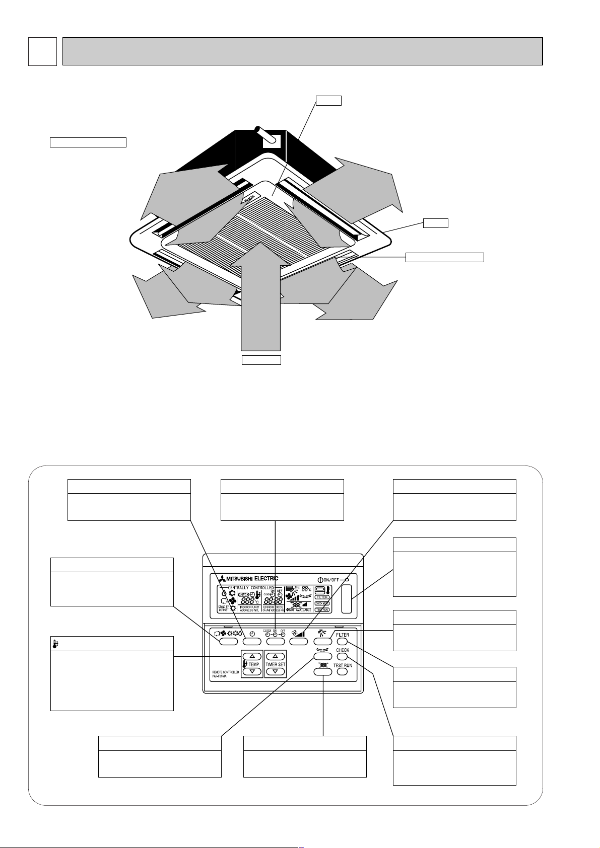
● Indoor (Main) Unit
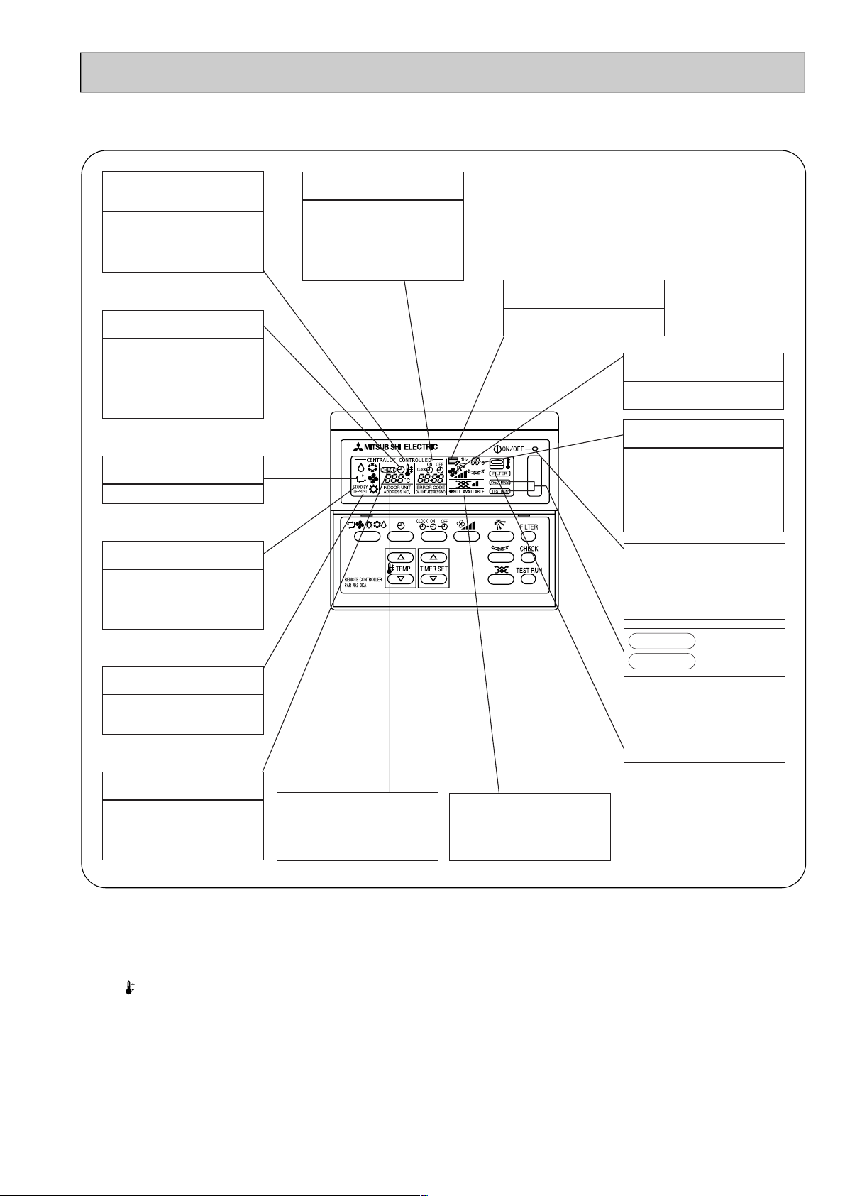
● Remote controller
● Operation buttons
[PAR-F25MA]
● Once the controls are set, the same operation mode can
be repeated by simply pressing the ON/OFF button.
Auto Air Swing Vane
Disperses airflow up and
down and adjusts the angle
of airflow direction.
Grille
Filters
Removes dust and pollutants
from intake air
Horizontal Air Outlet
Sets horizontal air flow automatically
during cooling or dehumidifying.
Air Intake
Intakes air from room.
Press this button to switch the cool,
electronic dry (dehumidify), automatic
and heater modes.
OPERATION SWITCH button
This sets the room temperature. The
temperature setting can be performed
in 1: units
Setting range
Cooler 19: to 30:
Heater 17: to 28:
TEMP. ADJUSTMENT button
This switches between continuous
operation and the timer operation.
TIMER button
This switches between the operation
and stop modes each time it is pressed.
The lamp on this button lights during
operation.
ON/OFF button
Only press this button to perform an
inspection check or test operation.
Do not use it for normal operation.
CHECK-TEST RUN button
This sets the ventilation fan speed.
VENTILATION button
This switches the horizontal fan
motion ON and OFF.
(This button does not operate in this
model)
(When the only LOSSNAY is connected.)
LOUVER button
This adjusts the vertical angle of the
ventilation.
AIR DIRECTION button
This resets the filter service indication
display
FILTER button
This sets the current time,
start time
and stop time.
TIME SETTING button
This sets the ventilation fan speed.
AIR SPEED button
5
Caution
● Only the Power display lights when the unit is stopped and power is supplied to the unit.
● When power is turned ON for the first time the (CENTRAL CTRL) display appears to go off momentarily but this is not a
malfunction.
● When the central control remote control unit, which is sold separately, is used the ON-OFF button, operation switch button
and TEMP. adjustment button do not operate.
● “NOT AVAILABLE” is displayed when the Air speed button is pressed.This indicates that this room unit is not equipped with
the fan direction adjustment function and the louver function.
● When power is turned ON for the first time, it is normal that “H0” is displayed on the room temperature indication (For max.
2minutes). Please wait until this “H0” indication has disappeared then start the operation.
4
CENTRALLY
CONTROLLED display
This indicates when the unit is
controlled by optional features such
as central control type remote
controller.
TIMER display
This indicates when the continuous
operation and time operation modes
are set.
It also displays the time for the timer
operation at the same time as when
it is set.
OPERATION MODE display
This indicates the operation mode.
STANDBY display
This indicates when the standby
mode is set from the time the sleep
operation starts until the heating air
is discharged.
DEFROST display
This indicates when the defrost
operation is performed.
CHECK display
This indicates when a malfunction
has occurred in the unit which should
be checked.
CLOCK display
The current time , start time and stop
time can be displayed in ten second
intervals by pressing the time switch
button. The start time or stop time is
always displayed during the timer
operation.
● Display
In this display example on the
bottom left, a condition where all
display lamps light is shown for
explanation purposes although this
differs from actual operation.
Operation lamp
This lamp lights during operation,
goes off when the unit stops and
flashes when a malfunction occurs.
POWER display
This lamp lights when electricity is
supplied to the unit.
SET TEMPERATURE display
This displays the selected setting
temperature.
FAN SPEED display
This displays the air direction.
ROOM TEMPERATURE display
The temperature of the suction air is
displayed during operation. The
display range is 8° to 39°C. The
display flashes 8°C when the actual
temperature is less than 8° and
flashes 39°C when the actual
temperature is greater than 39°C.
display
This display lights in the check mode
or when a test operation is
performed.
CHECK MODE
TEST RUN
FILTER display
This lamp lights when the filter need
to be cleaned.
AIR DIRECTION display
The selected fan speed is displayed.
3
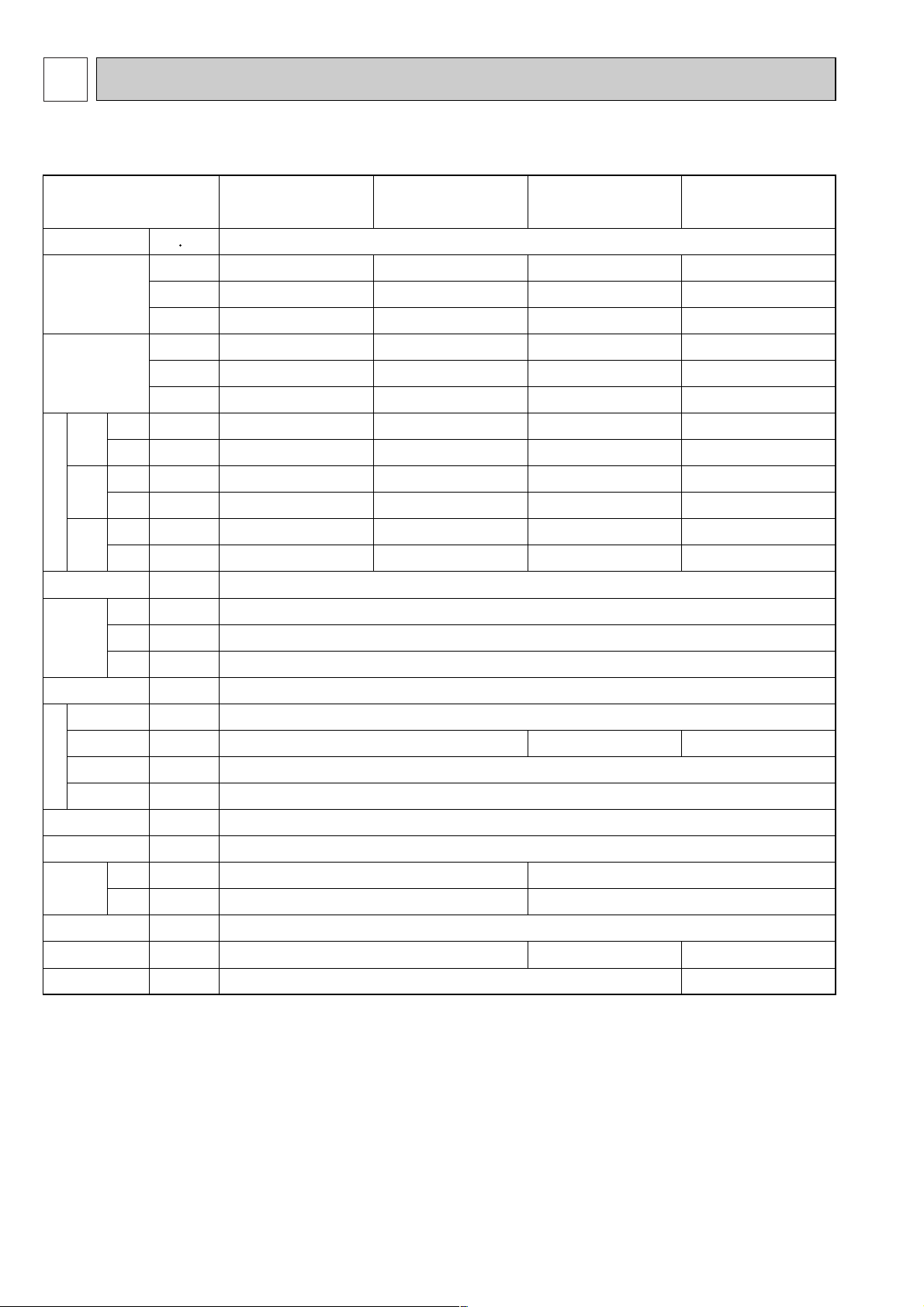
SPECIFICATIONS
3-1. Specification
Item
Power
Cooling
capacity
Heating
capacity
Cooling
Power
supply
Heating
Cooling
Starting
current
Heating
Cooling
Power
factor
Electric characteristic
(munsell symbol)
Dimensions
Heating
Exterior
Height
Width
Depth
Heat exchanger
Fan ✕ No
F
Air flow #3
a
External
n
static pressure
Fan motor
output
Insulator
Air filter
Pipe
dimensions
Gas
side
Liquid
side
Unit drain pipe size
Noise level
Product weight
V·Hz
kcal/h
BTU/h
kW
kcal/h
BTU/h
kW
kW
kW
A
A
%
%
mm
mm
mm
3
m
/min
Pa
kW
ømm
ømm
mm
dB
kg
PLFY-P32VKM.UK PLFY-P40VKM.UK PLFY-P50VKM.UK PLFY-P63VKM.UK
Single phase 220V-240V 50 Hz
3,150
12,500
3.7
3,550
14,100
4.1
0.13
0.13
0.60
0.60
90
90
4,000
15,900
4.7
4,500
17,900
5.2
0.13
0.13
0.60
0.60
90
90
5,000
19,800
5.8
5,600
22,200
6.6
0.14
0.14
0.64
0.64
91
91
6,300
25,000
7.3
7,100
28,200
8.3
0.15
0.15
0.68
0.68
92
92
-Unit : Galvanized sheets · Standard grill : ABS resin acrylic coating Munsell<0.70y 8.59/0.97>
298<30>
660<760>
660<760>
Cross fin
Turbo fan ✕ 1
15-14.5-14-13
16-15-14-13
17-16-15-14
0
0.030
Polyethylene sheet
PP honeycomb fabric
12.7(1/2")
6.35(1/4")
15.88(5/8")
9.52(3/8")
ID32 (PVC pipe VP-25 connectable)
35-34-32.5-31
19<3.7>
37-35.5-34-32
39-38-36.5-35
20<3.7>
Note 1. Rating conditions (JIS B 8615)
Cooling: Indoor: D.B. 27°C, W.B. 19.5°C
outdoor: D.B. 35°C
Heating: Indoor: D.B. 21°C
outdoor: D.B. 7°C, W.B. 6°C
Note 2. The number indicated in < > is just for the grill.
Note 3. Air flow and the noise level are indicated as High-Medium 1-Medium 2-Low.
6
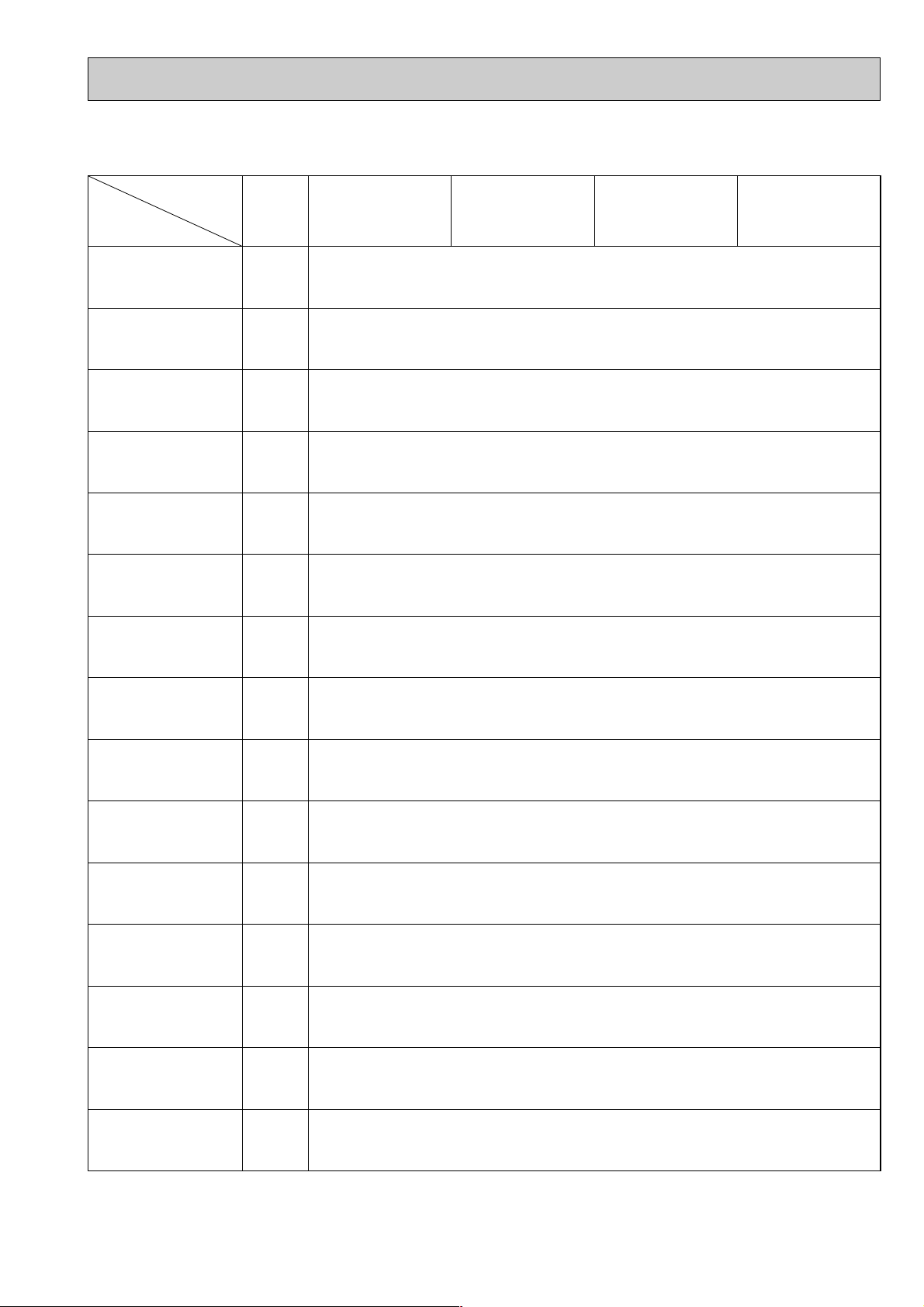
3-2. Electrical parts specifications
Model
Symbol
Parts name
PLFY-P32VKM.UK PLFY-P40VKM.UK PLFY-P50VKM.UK PLFY-P63VKM.UK
Transformer
Room temperature
thermistor
Liquid pipe thermistor
Gas pipe thermistor
Fuse
(Indoor controller board)
Fan motor
(with inner-thermostat)
inner-thermostat
(Fan motor)
Fan motor capacitor
T
TH21
TH22
TH23
FUSE
MF
C1
(Primary) 50/60Hz 220-240V (Secondary) (18.4V 1.7A)
Resistance 0°C/15kΩ, 10°C/9.6kΩ, 20°C/6.3kΩ, 25°C/5.4kΩ, 30°C/4.3kΩ, 40°C/3.0kΩ
Resistance 0°C/15kΩ, 10°C/9.6kΩ, 20°C/6.3kΩ, 25°C/5.4kΩ, 30°C/4.3kΩ, 40°C/3.0kΩ
Resistance 0°C/15kΩ, 10°C/9.6kΩ, 20°C/6.3kΩ, 25°C/5.4kΩ, 30°C/4.3kΩ, 40°C/3.0kΩ
250V 6.3A
6-pole OUTPUT 30W
PAI-V30F
OFF 125°C ± 5°C
ON 85°C ± 20°C
2.5µF ✕ 400V
Vane motor
(with limit switch)
Drain-up mechanism
Drain sensor
Linear expansion valve
Electric heater
(Dew prevention)
Power supply terminal
block
Transmission terminal
block
MV
DP
DS
LEV
H2
TB2
TB5
Heater resistance 82Ω/25°C
Thermistor resistance
0°C/15kΩ, 10°C/9.6kΩ, 20°C/6.3kΩ, 25°C/5.4kΩ, 30°C/4.3kΩ, 40°C/3.0kΩ
MC8 200V-240V
2.5/2W 5/6R.P.M
PJV-1002
INPUT 8/7.5W 24L/Hr
DC12V Stepping motor drive port
dimension 3.2Ω (0~2000pulse)
EDM-402ME
240V 28.8W
(L, N, Earth) 330V 30A
(M1, M2, S) 330V 30A
7
8
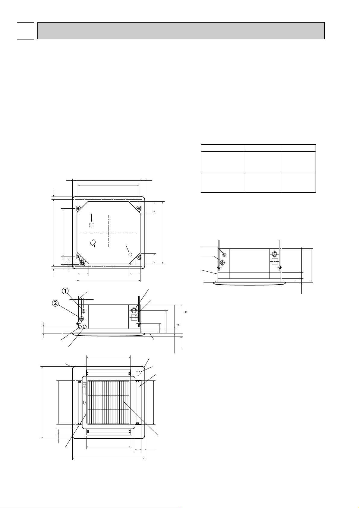
4
OUTLINES AND DIMENSIONS
PLFY-P32VKM.UK, PLFY-P40VKM.UK
PLFY-P50VKM.UK, PLFY-P63VKM.UK
Unit : mm
Models
PLFY-P32VKM.UK
PLFY-P40VKM.UK
Refrigerant pipe
(6.35mmdia)
flared connection
1/4F
Refrigerant pipe
(12.7mmdia)
flared connection
1/2F
Refrigerant pipe
(9.52mmdia)
flared connection
3/8F
Refrigerant pipe
(15.88mmdia)
flared connection
5/8F
PLFY-P50VKM.UK
PLFY-P63VKM.UK
12
Ceiling hole
Suspension bolt pitch
Suspension bolt M10 or
Air intake hole
Air outlet hole
Air intake grille
690~710 25~3525~35
640
660
466
460
66 35
760
117 117
117
435
13554
117
Ceiling hole
Suspension bolt pitch
Suspension bolt lower edge
Air outlet hole
Air outlet hole
690~710
25~35
25~35
65~80
760
460
466
6635
115
243
253
29830
54
+3
- 2
507
660
54
53
Terminal block for powersupply
Terminal block for
control
Drain hole
Drain hole ID32
VP-25 connection
W3/8
Feeding hole
(Drain pump)
Leave space of 10~15mm between the
top surface of the unit and the ceiling slab.
Ceiling surface
4-Auto vanes
Intake grille opening
/closing side
Vane motor
Decorative panel
Control wire entry
Refrigerant piping side
electric wire entry side
Power line entry
41 25
Liquid pipe
Gas pipe
Optional
high-efficiency filter
+3
-2
NOTE 1.The electrical parts box may be removed during servic ing. When connecting the power line and the control
wire,provide enough length to the electric wires.
NOTE 2.When installing the optional high-efficiency filter,the
dimension between the transom and ceiling shall be
more than 440mm. Also,when installing the optional
fresh air intake casement or the multi-functional case ment,the dimension between the transom and ceiling
shall be more than 440mm. (The optional high efficiency filter can also be installed.)
 Loading...