


Mitsubishi PLFY-P20VCM-E2.TH, PLFY-P25VCM-E2.TH, PLFY-P32VCM-E2.TH, PLFY-P40VCM-E2.TH Service Manual
SPLIT-TYPE, HEAT PUMP AIR CONDITIONERS
May 2009
No.OCH463
TECHNICAL & SERVICE MANUAL
R410A R407C 
 R22
R22
Indoor unit |
|
[Model names] [Service Ref.] |
|
PLFY-P20VCM-E2 |
PLFY-P20VCM-E2.TH |
|
|
PLFY-P25VCM-E2 |
PLFY-P25VCM-E2.TH |
|
|
PLFY-P32VCM-E2 |
PLFY-P32VCM-E2.TH |
|
|
PLFY-P40VCM-E2 |
PLFY-P40VCM-E2.TH |
|
|
Note :
•This manual describes only service data of the indoor units.
•RoHS compliant products have <G> mark on spec name plate.
|
CONTENTS |
|
|
|
|
.......................... |
|||
|
1. SAFETY PRECAUTION |
|
|
2 |
|
2. PART NAMES AND FUNCTIONS.......... 6 |
|||
|
................................... |
|||
|
3. SPECIFICATIONS |
|
|
9 |
|
................. |
11 |
||
|
4. 4-WAY AIR FLOW SYSTEM |
............ |
||
|
5. OUTLINES AND DIMENSIONS |
13 |
||
|
|
|
||
|
............................... |
14 |
||
|
6. WIRING DIAGRAM |
|
|
|
|
7. REFRIGERANT SYSTEM DIAGRAM |
...... |
15 |
|
|
|
|||
|
.......................... |
16 |
||
|
8. TROUBLESHOOTING |
|
|
|
|
9. DISASSEMBLY PROCEDURE............. |
23 |
||
Model name |
INDOOR UNIT |
|
|
|
indication |
PARTS CATALOG (OCB463) |
|
|
|
1 
 SAFETY PRECAUTION
CAUTIONS RELATED TO NEW REFRIGERANT
Cautions for units utilizing refrigerant R407C
Do not use the existing refrigerant piping.
The old refrigerant and lubricant in the existing piping contains a large amount of chlorine which may cause the lubricant deterioration of the new unit.
Use liquid refrigerant to charge the system.
If gas refrigerant is used to seal the system, the composition of the refrigerant in the cylinder will change and performance may drop.
Use “low residual oil piping”
If there is a large amount of residual oil (hydraulic oil, etc.) inside the piping and joints, deterioration of the lubricant will result.
Store the piping to be used indoors during installation and both ends sealed until just before brazing.
(Store elbows and other joints in a plastic bag.)
If dust, dirt, or water enters the refrigerant cycle, deterioration of the oil and compressor trouble may result.
Use ESTR , ETHER or HAB as the lubricant to coat flares and flange connection parts.
If large amount of mineral oil enters, that can cause deterioration of refrigerant oil etc.
Do not use a refrigerant other than R407C.
If another refrigerant (R22, etc.) is used, the chlorine in the refrigerant may cause the lubricant deterioration.
Use a vacuum pump with a reverse flow check valve.
The vacuum pump oil may flow back into the refrigerant cycle and cause the lubricant deterioration.
Ventilate the room if refrigerant leaks during operation. If refrigerant comes into contact with a flame, poisonous gases will be released.
[1]Cautions for service
·After recovering the all refrigerant in the unit, proceed to working.
·Do not release refrigerant in the air.
·After completing the repair service, recharge the cycle with the specified amount of liquid refrigerant.
2
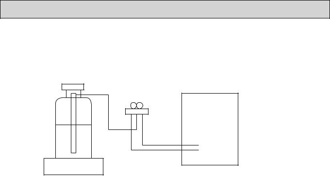
[2]Refrigerant recharging
(1)Refrigerant recharging process 1Direct charging from the cylinder
·R407C cylinder which is available on the market has a syphon pipe. ·Leave the syphon pipe cylinder standing and recharge it.
(By liquid refrigerant)
Unit
Gravimeter
(2) Recharge in refrigerant leakage case
·After recovering all the refrigerant in the unit, proceed to working. ·Do not release the refrigerant in the air.
·After completing the repair service, recharge the cycle with the specified amount of liquid refrigerant.
[3] Service tools
Use the below service tools as exclusive tools for R407C refrigerant.
No. |
Tool name |
Specifications |
|
|
|
1 |
Gauge manifold |
· Only for R407C |
|||
|
|
· Use the existing fitting SPECIFICATIONS. (UNF7/16) |
|||
|
|
· Use high-tension side pressure of 3.43MPa·G or over. |
|||
2 |
Charge hose |
· Only for R407C |
|||
|
|
· Use pressure performance of 5.10MPa·G or over. |
|||
3 |
Electronic scale |
|
|
|
|
|
|
|
|
||
4 |
Gas leak detector |
· Use the detector for R134a or R407C. |
|||
5 |
Adapter for reverse flow check |
· Attach on vacuum pump. |
|||
6 |
Refrigerant charge base |
|
|
|
|
|
|
|
|
||
7 |
Refrigerant cylinder |
· For R407C |
· Top of cylinder (Brown) |
||
|
|
· Cylinder with syphon |
|||
8 |
Refrigerant recovery equipment |
|
|
|
|
|
|
|
|
||
3

Cautions for units utilizing refrigerant R410A
Do not use the existing refrigerant piping.
The old refrigerant and lubricant in the existing piping contains a large amount of chlorine which may cause the lubricant deterioration of the new unit.
Use “low residual oil piping”
If there is a large amount of residual oil (hydraulic oil, etc.) inside the piping and joints, deterioration of the lubricant will result.
Store the piping to be used indoors during installation and both ends of the piping sealed until just before brazing. (Leave elbow joints, etc. in their packaging.)
If dirt, dust or moisture enters into refrigerant cycle, that can cause deterioration of refrigerant oil or malfunction of compressor.
Use ester oil, ether oil or alkylbenzene oil (small amount) as the refrigerant oil applied to flares and flange connections.
If large amount of mineral oil enters, that can cause deterioration of refrigerant oil etc.
Charge refrigerant from liquid phase of gas cylinder.
If the refrigerant is charged from gas phase, composition change may occur in refrigerant and the efficiency will be lowered.
Do not use refrigerant other than R410A.
If other refrigerant (R22 etc.) is used, chlorine in refrigerant can cause deterioration of refrigerant oil etc.
Use a vacuum pump with a reverse flow check valve.
Vacuum pump oil may flow back into refrigerant cycle and that can cause deterioration of refrigerant oil etc.
Use the following tools specifically designed for use with R410A refrigerant.
The following tools are necessary to use R410A refrigerant.
|
Tools for R410A |
|
Gauge manifold |
|
Flare tool |
Charge hose |
|
Size adjustment gauge |
Gas leak detector |
|
Vacuum pump adaptor |
Torque wrench |
|
Electronic refrigerant |
|
|
charging scale |
Handle tools with care.
If dirt, dust or moisture enters into refrigerant cycle, that can cause deterioration of refrigerant oil or malfunction of compressor.
Do not use a charging cylinder.
If a charging cylinder is used, the composition of refrigerant will change and the efficiency will be lowered.
Ventilate the room if refrigerant leaks during operation. If refrigerant comes into contact with a flame, poisonous gases will be released.
4

[1]Cautions for service
(1)Perform service after recovering the refrigerant left in unit completely.
(2)Do not release refrigerant in the air.
(3)After completing service, charge the cycle with specified amount of refrigerant.
(4)When performing service, install a filter drier simultaneously. Be sure to use a filter drier for new refrigerant.
[2]Additional refrigerant charge
When charging directly from cylinder
·Check that cylinder for R410A on the market is syphon type.
·Charging should be performed with the cylinder of syphon standing vertically. (Refrigerant is charged from liquid phase.)
Unit
Gravimeter
[3] Service tools
Use the below service tools as exclusive tools for R410A refrigerant.
No. |
Tool name |
Specifications |
||
1 |
Gauge manifold |
· Only for R410A |
||
|
|
· Use the existing fitting specifications. (UNF1/2) |
||
|
|
· Use high-tension side pressure of 5.3MPa·G or over. |
||
2 |
Charge hose |
· Only for R410A |
||
|
|
· Use pressure performance of 5.09MPa·G or over. |
||
3 |
Electronic scale |
|
|
|
|
|
|
||
4 |
Gas leak detector |
· Use the detector for R134a, R407C or R410A. |
||
5 |
Adapter for reverse flow check |
· Attach on vacuum pump. |
||
6 |
Refrigerant charge base |
|
|
|
|
|
|
||
7 |
Refrigerant cylinder |
· Only for R410A · Top of cylinder (Pink) |
||
|
|
· Cylinder with syphon |
||
8 |
Refrigerant recovery equipment |
|
|
|
|
|
|
||
5

2 
 PART NAMES AND FUNCTIONS
 Indoor Unit
Horizontal Air Outlet
Sets horizontal airflow automatically during cooling or dehumidifying.
Filter
Remove dust and pollutants from inhaled air.
Grille
Auto Air Swing Vane
Disperses airflow up and down and adjusts the angle of airflow direction.
Air Intake
Inhales air from room.
 Wired remote controller
Once the controllers are set, the same operation mode can be repeated by simply pressing the ON/OFF button.
Temperature setting buttons |
|
|
|
Down |
|
|
|
Up |
|
|
|
Timer Menu button |
|
|
|
(Monitor/Set button) |
|
|
|
Mode button (Return button) |
|
|
|
|
|
TEMP. |
|
Set Time buttons |
|
|
|
Back |
|
MENU |
ON/OFF |
Ahead |
BACK |
MONITOR/SET |
DAY |
|
|||
Timer On/Off button |
PAR-21MAA |
CLOCK |
|
(Set Day button) |
|
|
|
Opening the |
|
|
|
lid |
|
|
|
|
ON/OFF |
|
|
FILTER |
|
|
CHECK |
TEST |
OPERATION |
CLEAR |
|
Built-in temperature sensor
ON/OFF button
Fan Speed button
Filter  button (<Enter> button)
Test Run button
Check button (Clear button)
Airflow Up/Down button
Louver button
( Operation button)
To return operation number
Ventilation button
( Operation button)
To go to next operation number
6
 Wired remote controller
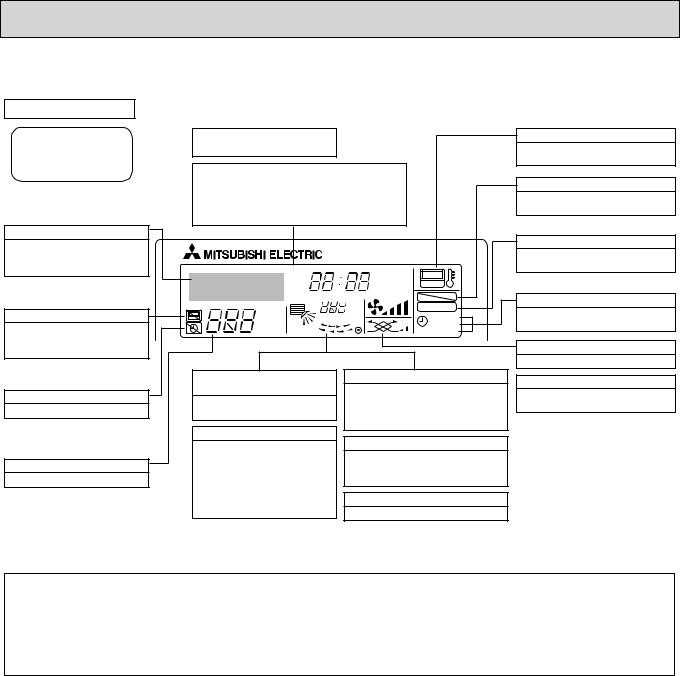
Display Section
For purposes of this explanation, |
Day-of-Week |
|
all parts of the display are shown |
Shows the current day of the week. |
|
as lit. During actual operation, only |
Time/Timer Display |
|
the relevant items will be lit. |
||
|
Shows the current time, unless the simple or Auto Off |
|
|
timer is set. |
|
|
If the simple or Auto Off timer is set, the time to be |
|
|
switched off is shown. |
|
Identifies the current operation
Shows the operating mode, etc. *Multilanguage display is available.
“Centrally Controlled” indicator
Indicates that operation from the remote controller has been prohibited by a master controller.
“Timer is Off” indicator
Indicates that the timer is off.
Temperature Setting
Shows the target temperature.
TIME SUN MON TUE WED THU FRI SAT |
||
TIMER |
Hr |
ON |
AFTER |
AFTER |
OFF |
ERROR CODE |
|
FUNCTION |
°F°C |
|
FILTER |
°F°C |
|
|
|
WEEKLY |
|
ONLY1Hr. |
|
SIMPLE |
|
AUTO OFF |
|
Up/Down Air Direction indicator
Shows the direction of the outcoming airflow.
“One Hour Only” indicator
Displayed if the airflow is set to low or downward during COOL or DRY mode. (Operation varies according to model.)
The indicator goes off in one hour, when the airflow direction also changes.
Room Temperature display
Shows the room temperature. The room temperature display range is 8~39 . The display blinks if the temperature is less than 8 or 39 or more.
Louver display
Indicates the action of the swing louver. Does not appear if the louver is not running.
 (Power On indicator)
Indicates that the power is on.
“Sensor” indication
Displayed when the remote controller sensor is used.
“Locked” indicator
Indicates that remote controller buttons have been locked.
“Clean The Filter” indicator
To be displayed on when it is time to clean the filter.
Timer indicators
The indicator comes on if the corresponding timer is set.
Fan Speed indicator
Shows the selected fan speed.
Ventilation indicator
Appears when the unit is running in Ventilation mode.
Note:
●“PLEASE WAIT” message
This message is displayed for approximately 3 minutes when power is supplied to the indoor unit or when the unit is recovering from a power failure.
●“NOT AVAILABLE” message
This message is displayed if an invalid button is pressed (to operate a function that the indoor unit does not have).
If a single remote controller is used to operate multiple indoor units simultaneously that are different types, this message will not be displayed as far as any of the indoor units is equipped with the function.
7
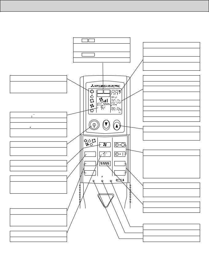
 Wireless remote controller


 display
OPERATION MODE display
Operation mode display indicates which operation mode is in effect.
 display
The vertical direction of air flow is indicated.

 display
FAN SPEED display indicates which fan speed has been selected.
ON/OFF button
The unit is turned ON and OFF alternately each time the button is pressed.
FAN SPEED SELECT button
Used to change the fan speed.
MODE SELECT button
Used to switch the operation mode between cooling, drying, fan, heating and auto mode.
 In case the outdoor unit is cool only type, the heating and auto mode are not available.
CHECK-TEST RUN button
Only press this button to perform an inspection check or test operation. Do not use it for normal operation.
VANE CONTROL button
Used to change the air flow
CHECK TESTRUN display
CHECK and TEST RUN display indicate that the unit is being checked or test-run.
MODELSELECT display
Blinks when model is selected.
CHECK TESTRUN
MODELSELECT 
 °C
°C
AMPM
AMPM
NOT AVAILABLE
ON/OFF  TEMP
TEMP
|
FAN |
AUTO STOP |
MODE |
VANE |
AUTO START |
CHECK |
LOUVER |
h |
TEST RUN |
|
min |
SET |
RESET CLOCK |
|
 display
Lights up while the signal is transmitted to the indoor unit when the button is pressed.
 display
SET TEMP. display indicates the set desired temperature.
CLOCK display
Displays the current time.
TIMER display
Displays when in timer operation or when setting timer.
“  ” “
” “ ” display
Displays the order of timer operation.
“
 ” “
” “
 ” display
Displays whether timer is on or off.
 button
SET TEMPERATURE button sets any desired room temperature.
TIMER CONTROL buttons
AUTO STOP (OFF timer): when this switch is set, the air conditioner will be automatically stopped at the preset time.
AUTO START (ON timer): when this switch is set, the air conditioner will be automatically started at the preset time.
h and min buttons
Buttons used to set the “hour and minute” of the current time and timer settings.
LOUVER button
Changes left/right airflow direction.
(Not available for this model.)
CLOCK button
RESET button
SET button
8

3 |
|
|
SPECIFICATIONS |
|
|
|
|
|
||||
3-1. SPECIFICATIONS |
|
|
|
|
|
|
|
|||||
|
|
|
|
|
|
|
|
|
|
|
||
Model |
|
|
|
|
PLFY-P20VCM-E2 |
PLFY-P25VCM-E2 |
PLFY-P32VCM-E2 |
|
PLFY-P40VCM-E2 |
|
||
|
|
|
|
|
|
|
|
|
|
|
||
Power source |
|
|
|
|
|
Single phase 220-230-240V 50Hz |
|
|
||||
Cooling capacity |
1 |
|
kW |
2.2 |
2.8 |
3.6 |
|
4.5 |
|
|||
(Nominal) |
|
1 |
|
kcal / h |
1,900 |
2,400 |
3,100 |
|
3,900 |
|
||
|
|
|
|
1 |
|
Btu / h |
7,500 |
9,600 |
12,300 |
|
15,400 |
|
|
|
|
|
2 |
|
kcal / h |
2,000 |
2,500 |
3,150 |
|
4,000 |
|
|
|
|
|
Power input |
|
kW |
0.05 |
0.05 |
0.06 |
|
0.06 |
|
|
|
|
|
Current input |
|
A |
0.23 |
0.23 |
0.28 |
|
0.28 |
|
Heating capacity |
3 |
|
kW |
2.5 |
3.2 |
4.0 |
|
5.0 |
|
|||
(Nominal ) |
|
3 |
|
kcal / h |
2,200 |
2,800 |
3,400 |
|
4,300 |
|
||
|
|
|
|
3 |
|
Btu / h |
8,500 |
10,900 |
13,600 |
|
17,100 |
|
|
|
|
|
Power input |
|
kW |
0.05 |
0.05 |
0.06 |
|
0.06 |
|
|
|
|
|
Current input |
|
A |
0.23 |
0.23 |
0.28 |
|
0.28 |
|
External finish |
|
|
|
|
|
Unit: Galvanized sheets with grey heat insulation |
|
|
||||
External dimension H x W x D |
|
mm |
208 × 570 × 570 |
208 × 570 × 570 |
208 × 570 × 570 |
|
208 × 570 × 570 |
|
||||
|
|
|
|
|
|
in. |
8-1/4" × 22-1/2" × 22-1/2" |
8-1/4" × 22-1/2" × 22-1/2" |
8-1/4" × 22-1/2" × 22-1/2" |
|
8-1/4" × 22-1/2" × 22-1/2" |
|
Net weight |
|
|
|
kg (lb) |
15.5 (35) |
15.5 (35) |
17 (38) |
|
17 (38) |
|
||
Decoration panel |
Model |
|
SLP-2AAW or SLP-2ALW |
SLP-2AAW or SLP-2ALW |
SLP-2AAW or SLP-2ALW |
SLP-2AAW or SLP-2ALW |
|
|||||
|
|
|
|
External finish |
|
|
White Munsell(6.4Y 8.9/0.4) |
|
|
|||
|
|
|
|
Dimension |
|
mm |
20 × 650 × 650 |
20 × 650 × 650 |
20 × 650 × 650 |
|
20 × 650 × 650 |
|
|
|
|
|
H × W × D |
|
in. |
13/16" × 25-5/8" × 25-5/8" |
13/16" × 25-5/8" × 25-5/8" |
13/16" × 25-5/8" × 25-5/8" |
|
13/16" × 25-5/8" × 25-5/8" |
|
|
|
|
|
Net Weight |
|
kg (lb) |
3 (7) |
3 (7) |
3 (7) |
|
3 (7) |
|
|
|
|
|
Cord heater |
|
kW |
0.015 |
0.015 |
0.015 |
|
0.015 |
|
Heat exchanger |
|
|
|
|
Cross fin (Aluminum fin and copper tube) |
|
|
|||||
FAN |
|
Type × Quantity |
|
|
Turbo fan × 1 |
|
|
|||||
|
|
|
|
External static press. |
0Pa (0mmH2O) |
0Pa (0mmH2O) |
0Pa (0mmH2O) |
|
0Pa (0mmH2O) |
|
||
|
|
|
|
Motor type |
|
|
Single phase induction motor |
|
|
|||
|
|
|
|
Motor output |
|
kW |
0.011 |
0.015 |
0.02 |
|
0.02 |
|
|
|
|
|
Driving mechanism |
|
|
Direct-driven by motor |
|
|
|||
|
|
|
|
Airflow rate |
|
m3 / min |
8-9-10 |
8-9-10 |
8-9-11 |
|
8-9-11 |
|
|
|
|
|
(Low-Mid-High) |
|
L / s |
133-150-167 |
133-150-167 |
133-150-183 |
|
133-150-183 |
|
|
|
|
|
|
|
cfm |
283-318-353 |
283-318-353 |
283-318-388 |
|
283-318-388 |
|
Noise level (Low-Mid-High) |
|
dB <A> |
28-31-35 |
29-31-37 |
29-33-38 |
|
30-34-39 |
|
||||
(measured in anechoic room) |
|
|
|
|
||||||||
|
|
|
|
|
|
|
|
|||||
Insulation material |
|
|
|
|
Polyethylene foam |
|
|
|||||
Air filter |
|
|
|
|
|
PP honeycomb fabric (long life type) |
|
|
||||
Protection device |
|
|
|
|
Fuse |
|
|
|||||
Refrigerant control device |
|
|
LEV |
|
|
|||||||
Connectable outdoor unit |
|
|
R410A, R407C, R22 CITY MULTI |
|
|
|||||||
Diameter of |
|
Liquid |
|
mm (in.) |
ø6.35 (ø1/4") Flare |
ø6.35 (ø1/4") Flare |
ø6.35 (ø1/4") Flare |
|
ø6.35 (ø1/4") Flare |
|
||
refrigerant pipe |
Gas |
|
mm (in.) |
ø12.7 (ø1/2") Flare |
ø12.7 (ø1/2") Flare |
ø12.7 (ø1/2") Flare |
|
ø12.7 (ø1/2") Flare |
|
|||
Field drain pipe size |
|
|
mm (in.) |
|
O.D. 32mm (1-1/4") (PVC pipe VP-25 connectable) |
|
|
|||||
Standard |
|
Document |
|
|
Installation manual, Instruction book |
|
|
|||||
attachment |
|
Accessory |
|
|
Drain hose I.D. 32mm (1-1/4"), Wireless junction cable |
|
|
|||||
Remark |
|
Optional parts |
|
|
Decoration panel : SLP-2AAW or SLP-2ALW |
|
|
|||||
|
|
|
|
|
|
|
|
*PLFY-P-VCM-E2 should use together with Decoration panel. |
|
|||
|
|
|
|
|
|
|
|
|
|
|
|
|
|
|
|
|
|
|
|
|
Installation |
Details on foundation work, duct work, insulation work, electrical wiring, power source switch, and other items shall be referred to |
||||
|
|
the Installation Manual. |
|
|
|
|
|
|
|
|
|
|
|
Note : |
1 Nominal cooling condition |
|
2 Nominal cooling condition |
3 Nominal heating condition |
|
Unit converter |
Indoor : |
27˚CDB/19˚CWB (81˚FDB/66˚FWB) |
27˚CDB/19.5˚CWB (81˚FDB/67˚FWB) |
20˚CDB (68˚FDB) |
kcal |
= kW × 860 |
|
Outdoor : |
35˚CDB (95˚FDB) |
|
35˚CDB (95˚FDB) |
7˚CDB/6˚CWB (45˚FDB/43˚FWB) |
||
|
Btu/h = kW × 3,412 |
|||||
Pipe length : |
7.5 m (24-9/16 ft) |
|
5 m (16-3/8 ft) |
7.5 m (24-9/16 ft) |
||
|
cfm |
= m3/min x 35.31 |
||||
Level difference : |
0 m (0 ft) |
|
0 m (0 ft) |
0 m (0 ft) |
||
* Nominal conditions 1, 3 are subject to JIS B8615-1. |
|
|
|
lb |
= kg / 0.4536 |
|
* Due to continuing improvement, above specification may be subject to change without notice. |
|
|
|
|||
9
 Loading...