


Mitsubishi PLA-P3AA.UK, PLA-P4AA.UK, PLA-P5AA.UK, PLA-P6AA.UK, PLA-P3AA1.UK Service Manual
...SPLIT-TYPE AIR CONDITIONERS
No.OC241
REVISED EDITION-A
TECHNICAL & SERVICE MANUAL
Series PLA
Indoor unit [Model names]
PLA-P3AA
PLA-P4AA
PLA-P5AA
PLA-P6AA
Ceiling Cassettes R407C
[Service Ref.]
PLA-P3AA.UK PLA-P3AA1.UK PLA-P4AA.UK PLA-P4AA1.UK PLA-P5AA.UK PLA-P5AA1.UK PLA-P6AA.UK PLA-P6AA1.UK
•PLA-P3AA1.UK, PLA-P4AA1.UK PLA-P5AA1.UK and PLA-P6AA1.UK are added in REVISED EDITION-A. Outdoor units PU(H)-P3,4VGAA.UK and PU(H)-P3,4,5,6YGAA.UK which are connected to those indoor units are also added in it.
•Please void OC241.
•Refer to the OCT03 REVISED EDITION-C as for control relation. This manual does not cover outdoor units.
When serving them, please refer to the service manual No.OC180 REVISED EDITION-A, OC261 and this manual in a set.
INDOOR UNIT
CHECK TESTRUN |
|
|
|
|
|
MODEL SELECT |
˚C |
|
|
|
|
|
AMPM |
|
|
|
|
|
AMPM |
|
|
|
|
|
|
FILTER |
|
1Hr. |
|
|
|
CENTRALLY CONTROLLED |
|
||
ON/OFF |
TEMP |
CHECK MODE |
ON OFF |
|
˚C |
|
|
CHECK |
CLOCK |
|
|
ON/OFF |
|
TEST RUN |
|
|
FILTER |
|
|
˚C |
|
CHECK MODE |
|
|
|
STAND BY |
|
TEST RUN |
|
|
|
DEFROST |
ERROR CODE |
NOT AVAILABLE |
FUNCTION |
|
|
TEMP. |
|
ON/OFF |
|
CONTENTS
1.TECHNICAL CHANGES ············
2.COMBINATION OF INDOOR AND OUTDOOR UNITS··3
3.SAFETY PRECAUTION ·············
4.PART NAMES AND FUNCTIONS ········
5.SPECIFICATIONS ···············
6.DATA ·····················
7.OUTLINES AND DIMENSIONS ·········
8.WIRING DIAGRAM ················
9.REFRIGERANT SYSTEM DIAGRAM·········
10.TROUBLESHOOTING ·············
11.DISASSEMBLY PROCEDURE ··········
12.PARTS LIST ··················
13.OPTIONAL PARTS ···············
PLA-P•AA.UK PLA-P•AA1.UK |
PLA-P•AA.UK |
PLA-P•AA1.UK |
WIRELESS REMOTE |
WIRED REMOTE |
CONTROLLER |
CONTROLLER |

1 
 TECHNICAL CHANGES
PLA-P3AA.UK PLA-P3AA1 PLA-P4AA.UK PLA-P4AA1.UK PLA-P5AA.UK PLA-P5AA1 PLA-P6AA.UK PLA-P6AA1.UK
REMOTE CONTROLLER has changed. (PAR-S27A-E PAR-20MAA-E, PAR-SL95A-E PAR-SL97A-E)
Outdoor unit which are connected to PLA-P•AA.UK and PLA-P•AA1.UK have been added.
2
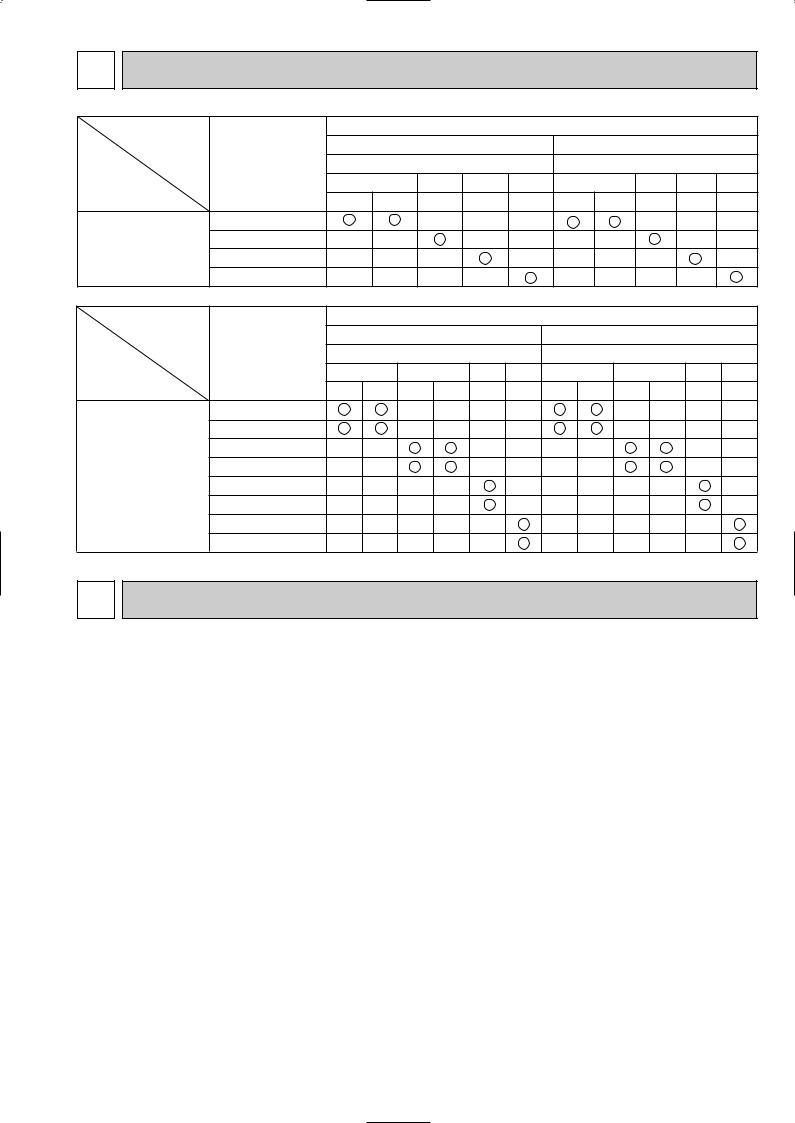
2 COMBINATION OF INDOOR AND OUTDOOR UNITS
|
|
|
|
|
|
Outdoor unit |
|
|
|
|
|
|
|
|
Heat pump type |
|
|
Cooling only type |
|
||||
|
Indoor unit |
|
|
PUH-P |
|
|
|
|
PU-P |
|
|
|
3 |
|
4 |
5 |
6 |
3 |
|
4 |
5 |
6 |
|
|
|
|
|
||||||||
|
|
VGA |
YGA |
YGA |
YGA |
YGA |
VGA |
YGA |
YGA |
YGA |
YGA |
Heat pump without |
PLA-P3AA.UK |
|
|
— |
— |
— |
|
|
— |
— |
— |
electric heater |
PLA-P4AA.UK |
— |
— |
|
— |
— |
— |
— |
|
— |
— |
or |
PLA-P5AA.UK |
— |
— |
— |
|
— |
— |
— |
— |
|
— |
Cooling only |
|
|
|||||||||
PLA-P6AA.UK |
— |
— |
— |
— |
|
— |
— |
— |
— |
|
|
|
|
|
|||||||||
|
|
|
|
|
|
|
Outdoor unit |
|
|
|
|
||
|
|
|
|
Heat pump type |
|
|
Cooling only type |
|
|||||
|
Indoor unit |
|
|
PUH-P |
|
|
|
|
PU-P |
|
|
||
|
|
3 |
4 |
|
5 |
6 |
|
3 |
4 |
|
5 |
6 |
|
|
|
|
|
|
|
||||||||
|
|
VGAA.UK |
YGAA.UK VGAA.UK YGAA.UK YGAA.UK |
YGAA.UK |
VGAA.UK |
YGAA.UK |
VGAA.UK |
YGAA.UK |
YGAA.UK |
YGAA.UK |
|||
|
PLA-P3AA.UK |
|
|
— |
— |
— |
— |
|
|
— |
— |
— |
— |
|
PLA-P3AA1.UK |
|
|
— |
— |
— |
— |
|
|
— |
— |
— |
— |
Heat pump without |
PLA-P4AA.UK |
— |
— |
|
|
— |
— |
— |
— |
|
|
— |
— |
PLA-P4AA1.UK |
— |
— |
|
|
— |
— |
— |
— |
|
|
— |
— |
|
electric heater |
|
|
|
|
|||||||||
or |
PLA-P5AA.UK |
— |
— |
— |
— |
|
— |
— |
— |
— |
— |
|
— |
Cooling only |
PLA-P5AA1.UK |
— |
— |
— |
— |
|
— |
— |
— |
— |
— |
|
— |
|
|
|
|||||||||||
|
PLA-P6AA.UK |
— |
— |
— |
— |
— |
|
— |
— |
— |
— |
— |
|
|
PLA-P6AA1.UK |
— |
— |
— |
— |
— |
|
— |
— |
— |
— |
— |
|
3 SAFETY PRECAUTION
Cautions for devices that use R407C refrigerant.
· Do not use the existing refrigerant piping.
-The old refrigerant and lubricating oil in the existing piping contains a large amount of chlorine which may cause the lubricating oil of the new unit to deteriorate.
· Use “low residual oil piping”.
-If there is a large amount of residual oil (hydraulic oil, etc.) inside the piping and joints, deterioration of the lubricating oil will result.
·Store the piping to be used during installation indoors and keep both ends of the piping sealed until just before brazing. (Store elbows and other joints in a plastic bag.)
-If dust, dirt, or water enters the refrigerant cycle, deterioration of the oil and compressor trouble may result.
·Use Suniso 4GS or 3GS (small amount) as the lubricating oil to coat flares and flange connection parts.
-The lubricating oil used with the air conditioner is highly hygroscopic. If it is used, water may be mixed in and deterioration of the lubricating oil may result.
· Use liquid refrigerant to charge the system.
-If gas refrigerant is used to charge the system, the composition of the refrigerant in the cylinder will change and performance may drop.
· Do not use a refrigerant other than R407C.
-If another refrigerant (R22, etc.) is used, the chlorine in the refrigerant may cause the lubricating oil to deteriorate.
· Use a vacuum pump with a reverse flow check valve.
-The vacuum pump oil may flow back into the refrigerant cycle and cause the lubricating oil to deteriorate.
3
[1] Service tools
Use the below service tools as exclusive tools for R407C refrigerant.
No. |
Tool name |
Specifications |
1 |
Gauge manifold |
·Only for R407C. |
|
|
·Use the existing fitting SPECIFICATIONS. (UNF7/16) |
|
|
·Use high-tension side pressure of 35kgf/cm2 or over. |
2 |
Charge hose |
·Only for R407C. |
|
|
·Use pressure performance of 52kgf/cm2 or over. |
3 |
Electronic scale |
|
4 |
Gas leak detector |
·Use the detector for R134a or R407C. |
5 |
Adapter for reverse flow check. |
·Attach on vacuum pump. |
6 |
Refrigerant charge base. |
|
7 |
Refrigerant cylinder. |
·For R407C ·Top of cylinder (Brown) |
|
|
·Cylinder with syphon |
8 |
Refrigerant recovery equipment. |
|
[2] Notice on repair service
·After recovering all the refrigerant in the unit, work may be started. ·Do not release the refrigerant in the air.
·After completing the repair service, recharge the system with the specified amount of the liquid refrigerant.
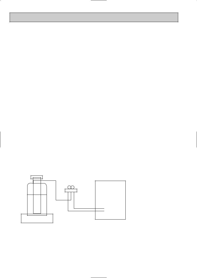
[3]Refrigerant recharging
(1)Refrigerant recharging process
Direct charging from the cylinder.
·Confirm that the cylinder is suitable for syphoning.
·Raise the cylinder and recharge the unit by syphoning liquid refrigerant.
Unit
Gravimeter
(2) Recharge when refrigerant leakage has occurred.
·After recovering all the refrigerant in the unit, work may be started.
·Do not release the refrigerant in the air.
·After completing the repair service, recharge the system with the specified amount of the liquid refrigerant.
4
4 
 PART NAMES AND FUNCTIONS
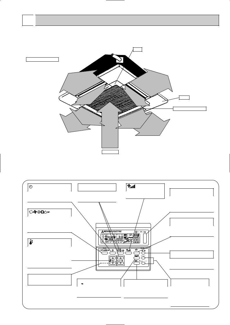
● Indoor (Main) Unit
PLA-P3AA.UK, PLA-P4AA.UK, PLA-P5AA.UK, PLA-P6AA.UK PLA-P3AA1.UK, PLA-P4AA1.UK, PLA-P5AA1.UK, PLA-P6AA1.UK
Filter
Removes dust and pollutants
from intake air
Horizontal Air Outlet
Sets airflow of horizontal automatically during cooling or dehumidifying.
Grille
Auto Air Swing Vane Disperses airflow up and down and adjusts the angle of airflow direction.
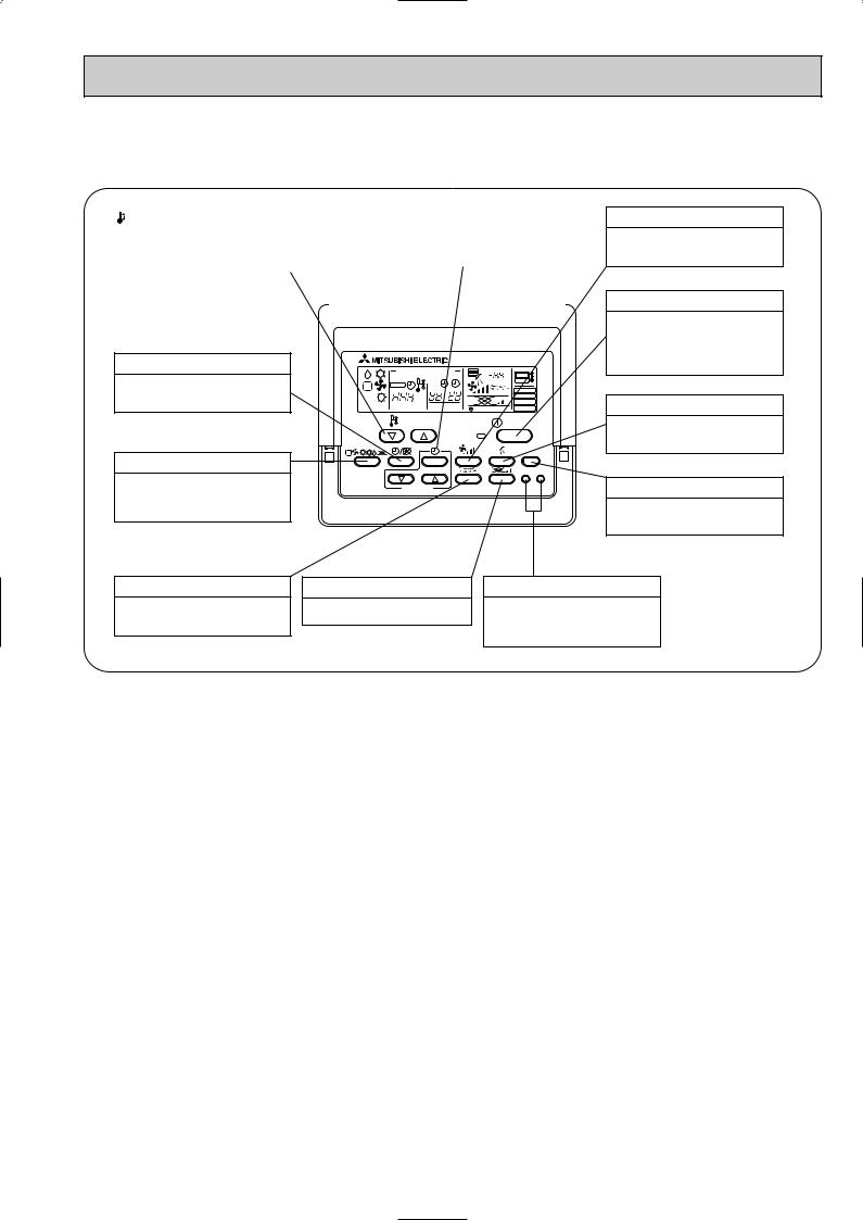
● Wired remote controller
Air Intake
Intakes air from room.
On the controls are set, the same operation mode can be repeated by simply pressing the ON/OFF button.
PLA-P3AA.UK, PLA-P4AA.UK, PLA-P5AA.UK, PLA-P6AA.UK ● Operation buttons
button
This switches between continuous operation and the timer operation.
button
Press this button to switch the cooling, electronic dry (dehumidify), automatic and heating modes.


 button
This sets the current time. start time and stop time.
button
This sets the ventilation fan speed.
TEMP. button
This sets the room temperature, The temperature setting can be performed in 1°C units
Setting range
Cooling 19°C to 30°C Heating 17°C to 28°C
This model name of the remote controller is indicated.
PAR-S27AA


 button
This switches the horizontal fan motion ON and OFF.
(Not available for this model.)


 button
This sets the ventilation fan speed.
ON/OFF button
This switches between the operation and stop modes each time it is pressed. The lamp on this button lights during operation.
 button
This adjusts the vertical angle of the ventilation.
FILTER button
This resets the filter cleaning indication display.
CHECK-TEST RUN button
Only press this button to perform an inspection check or test operation, Do not use it for normal operation.
5
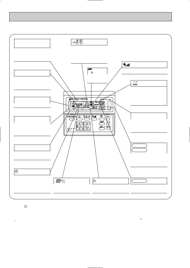
● Display
CENTRALLY CONTROLLED display
This indicates when the unit is controlled by optional features such as central control type remote controller.
CHECK display
This indicates when a malfunction has occurred in the unit which should be checked.
OPERATION MODE display
This indicates the operation mode.
STANDBY display
The [STANDBY] symbol is only displayed from the time the heating operation starts until the heated air begins to blow.
display
The current time , start time and stop time can be displayed in ten second intervals by pressing the time setting button. The start time or stop time is always displayed during the timer operation.
 display
This displays the air direction.
In this display example on the bottom left, a condition where all display lamps light is shown for explanation purposes although this differs from actual operation.
display
The selected fan speed is displayed.


 display
The temperature of the suction air is displayed during operation. The display range is 10° to 35°C. The display flashes 10°C when the actual temperature is less than 10° and flashes 35°C when the actual temperature is greater than 35°C.
Operation lamp
This lamp lights during operation, goes off when the unit stops and flashes when a malfunction occurs.
DEFROST display
This indicates when the defrost operation is performed.
display
This indicates when the continuous operation and time operation modes are set.
It also display the time for the timer operation at the same time as when it is set.
display
This displays the selected setting temperature.
CHECK MODE
display
TEST RUN
This display lights in the check mode or when a test operation is performed.
display |
FILTER |
display |
This lamp lights when electricity is |
This lamp lights when the filter need |
|
supplied to the unit. |
to be cleaned. |
|
Caution
●Only the  display lights when the unit is stopped and power supplied to the unit.
●When power is turned ON for the first time the (CENTRAL CTRL) display appears to go off momentarily but this is not a malfunction.
●When the central control remote control unit, which is sold separately, is used the ON-OFF button, 


 button and
 TEMP. button do not operate.
●“NOT AVAILABLE” is displayed when the 


 button are pressed.This indicates that this room unit is not equipped with the fan direction adjustment function and the louver function.
●When power is turned ON for the first time , it is normal that “HO” is displayed on the room temperature indication (For max. 2minutes ).
Please wait until this “HO” indication disappear than start the operation.
6
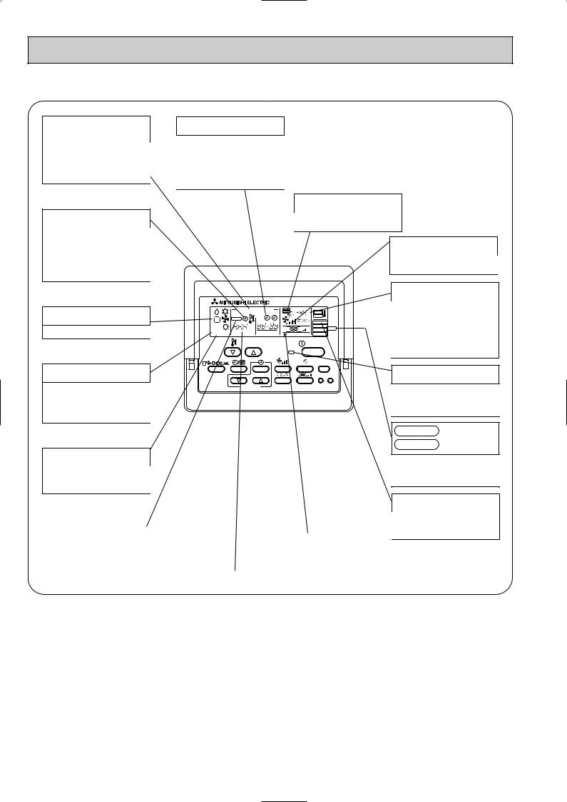
PLA-P3AA1.UK, PLA-P4AA1.UK, PLA-P5AA1.UK, PLA-P6AA1.UK
● Operation buttons
|
|
TEMP. ADJUSTMENT button |
|
|
TIME SETTING button |
|
|
|
|
||||
|
|
|
|
|
|
|
|
This sets the room temperature. The |
|
|
This sets the current time, start time |
|
|
|
temperature setting can be performed |
|
|
and stop time. |
|
|
|
in 1: units |
|
|
|
|
|
|
|
|
|
|
||
|
|
Setting range |
|
|
|
|
|
|
Cooler 19: to 30: |
|
|
|
|
|
|
Heater 17: to 28: |
|
|
|
|
|
|
|
|
|
|
|
TIMER button
This switches between continuous operation and the timer operation.
OPERATION SWITCH button
Press this button to switch the cooler, electronic dry (dehumidify), automatic and heater modes.
|
CENTRALLY CONTROLLED |
1Hr. |
|
|
|
|
ON OFF |
|
˚C |
|
CHECK |
CLOCK |
|
|
|
|
|
|
|
|
|
|
|
FILTER |
|
˚C |
|
|
CHECK MODE |
STAND BY |
ERROR CODE |
|
TEST RUN |
|
|
NOT AVAILABLE |
FUNCTION |
||
DEFROST |
|
|||
|
|
|||
|
TEMP. |
|
|
ON/OFF |
FILTER
CHECK TEST
PAR-20MAA |
TIMER SET |
AIR SPEED button
This sets the ventilation fan speed.
ON/OFF button
This switches between the operation and stop modes each time it is pressed. The lamp on this button lights during operation.
AIR DIRECTION button
This adjusts the vertical angle of the ventilation.
FILTER button
This resets the filter service indication display
LOUVER button
This switch the horizontal fan motion ON and OFF.
(Not available for this model.)
VENTILATION button
This sets the ventilation fan speed.
CHECK-TEST RUN button
Only press this button to perform an inspection check or test operation. Do not use it for normal operation.
7
● Display
CENTRALLY CONTROLLED display
This indicates when the unit is controlled by optional features such as central control type remote controller.
CLOCK display
The current time , start time and stop time can be displayed in ten second intervals by pressing the time switch button. The start time or stop time is always displayed during the timer operation.
In this display example on the bottom left, a condition where all display lamps light is shown for explanation purposes although this differs from actual operation.
TIMER display
This indicates when the continuous operation and time operation modes are set.
It also display the time for the timer operation at the same time as when it is set.
OPERATION MODE display
This indicates the operation mode.
STANDBY display
The [STANDBY] symbol is only displayed from the time the heating operation starts unit the heated air begins to blow.
DEFROST display
This indicates when the defrost operation is performed.
AIR DIRECTION display
This displays the air direction.
|
CENTRALLY CONTROLLED |
1Hr. |
|
|
|
|
ON OFF |
|
˚C |
|
CHECK |
CLOCK |
|
|
|
|
|
|
|
|
|
|
|
FILTER |
|
˚C |
|
|
CHECK MODE |
STAND BY |
ERROR CODE |
|
TEST RUN |
|
|
NOT AVAILABLE |
FUNCTION |
||
DEFROST |
|
|||
|
|
|||
|
TEMP. |
|
|
ON/OFF |
FILTER
CHECK TEST
PAR-20MAA |
TIMER SET |
AIR SPEED display
The selected fan speed is displayed.
ROOM TEMPERATURE display
The temperature of the suction air is displayed during operation. The display range is 8°C to 39°C. The display flashes 8°C when the actual temperature is less than 8°C and flashes 39°C when the actual temperature is greater than 39°C.
Operation lamp
This lamp lights during operation, goes off when the unit stops and flashes when a malfunction occurs.
CHECK MODE
display
TEST RUN
This display lights in the check mode or when a test operation is performed.
CHECK display |
|
|
|
|
|
|
|
SET TEMPERATURE display |
|
POWER display |
|
This indicates when a malfunction |
|||||
|
|
|
|
||
has occurred in the unit which should |
|
This displays the selected setting |
|
This lamp lights when electricity is |
|
be checked. |
|
|
|||
|
temperature. |
|
supplied to the unit. |
||
|
|
|
|||
|
|
|
|
|
Caution
FILTER display
This lamp lights when the filter need to be cleaned.
●Only the Power display lights when the unit is stopped and power supplied to the unit.
●When the central control remote control unit, which is sold separately, is used the ON-OFF button, operation switch button and  TEMP. adjustment button do not operate.
●“NOT AVAILABLE” is displayed when the Air speed button are pressed.This indicates that this room unit is not equipped with the fan direction adjustment function and the louver function.
●When power is turned ON for the first time, it is normal that “H0” is displayed on the room temperature indication (For max. 2minutes). Please wait until this “H0” indication disappear then start the operation.
8
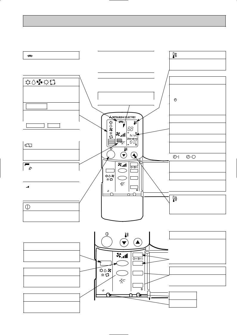
● Wireless remote controller
PLA-P3AA.UK, PLA-P4AA.UK, PLA-P5AA.UK, PLA-P6AA.UK
● When cover is open.
display
Lights up while transmission to the indoor unit is mode using switches.
display
OPERATION MODE display
Operation mode display indicates which operation mode is in effect.
• FUNCTION display
Lights up when function are set.
• TEST RUN • CHECK display
CHECK&TEST RUN display indicates that the unit is being checked or test-run.
display
Displays when batteries are dead.
 display
The vertical direction of airflow is indicated.

 display
FAN SPEED display indicates which fan speed has been selected.
display
The unit is turned ON and OFF alternately each time the button is pressed.
● When cover is open.
MODE SELECT button
Used to switch the operation mode between cooling , drying , blowing , heating and auto mode.
FAN SPEED SELECT button
Used to change the fan speed.
VANE CONTROL button
Used to change the airflow direction.
ADDRESS display |
|
|
display |
|||||
Displays the refrigerant address. |
SET TEMP. display indicates desired tempera- |
|||||||
|
|
|
||||||
UNIT NO. display |
ture set. |
|
|
|
||||
|
|
|
|
|
||||
Displays the number of unit.. |
|
|
|
|
|
|||
FUNCTION NO. display |
CLOCK display |
|||||||
|
|
|
|
|
||||
Displays the mode. |
|
DIsplays the current time. |
||||||
|
|
|
||||||
SELECTION NO. display |
“ |
”display |
||||||
Displays the selection number.. |
||||||||
|
|
|
|
|
||||
|
|
|
Flashes when the current time is displayed. |
|||||
|
|
|
TIMER display |
|||||
|
ADDRESS |
|
Displays when in timer operation or when set- |
|||||
|
UNIT No. |
|
||||||
|
FUNCTION No. |
˚C |
ting timer. |
|
|
|||
|
SELECTION No. |
|
|
|||||
|
|
AM |
“ |
” “ |
|
” display |
||
|
|
PM |
|
|||||
FUNCTION |
|
AM |
|
|
|
|
||
TEST RUN |
|
|
|
|
|
|
||
|
PM |
|
|
|
|
|
||
|
|
|
|
|
|
|
||
CHECK |
|
|
|
|
|
|
|
|
|
|
TEMP. |
Displays the order of timer operation. |
|||||
|
|
|
|
|
|
|
||
ON/OFF |
|
|
“ |
|
” “ |
|
” display |
|
|
|
|
|
|
||||
|
|
START |
Displays whether timer is on or off. |
|||||
|
|
|
||||||
MODE |
FAN |
STOP |
|
|
|
|
|
|
|
VANE |
HR. |
“ ▼ |
” “ |
▼ |
” display |
||
|
|
|
|
|
|
|||
|
|
|
Displays when the current time and the timer |
|||||
|
|
MIN. |
time can be changed. |
|||||
RESET
TEMP. button
TEMP.
ON/OFF
|
|
START |
MODE |
FAN |
STOP |
 VANE HR.
MIN.
RESET
SET TEMPERATURE button sets any desired room temperature.
TIMER CONTROL buttons
STOP (OFF timer): when this switch is set, the air conditioner will be automatically stopped at the preset time.
START (ON timer): when this switch is set, the air conditioner will be automatically started at the preset time.
HR. and MIN.buttons
Buttons used to set the “hour and minute” of the current time and timer settings.
 button
RESET button
9

PLA-P3AA1.UK, PLA-P4AA1.UK, PLA-P5AA1.UK, PLA-P6AA1.UK
CHECK TESTRUN display
CHECK&TEST RUN display indicates that the unit is being checked or test-run.


 display
OPERATION MODE display
Operation mode display indicates which operation mode is in effect.

 display
The vertical direction of air flow is indicated.

 display
FAN SPEED display indicates which fan speed has been selected.
ON/OFF button
The unit is turned ON and OFF alternately each time the button is pressed.
FAN SPEED SELECT button
Used to change the fan speed.
MODE SELECT button
Used to switch the operation mode between cooling, drying, blowing, heating and auto mode.
wIn case the outdoor unit is cool only type, the heating mode is not available.
CHECK-TEST RUN button
Only press this button to perform an inspection check or test operation.
Do not use it for normal operation.
VANE CONTROL button
Used to change the air flow direction.
MODEL SELECT display
Blinks when model is selected.
CHECK TESTRUN
MODEL SELECT 
 ˚C
˚C
AMPM
AMPM
NOT AVAILABLE
ON/OFF  TEMP
TEMP
|
FAN |
AUTO STOP |
MODE |
VANE |
AUTO START |
CHECK |
LOUVER |
h |
TEST RUN |
|
min |
SET |
RESET CLOCK |
|
 display
Lights up while transmission to the indoor unit is mode using switches.
 display
SET TEMP. display indicates desired temperature set.
CLOCK display
Displays the current time.
TIMER display
Displays when in timer operation or when setting timer.
“  ” “
” “ ” display
Displays the order of timer operation.
“
 ” “
” “
 ” display
Displays whether timer is on or off.
 button
SET TEMPERATURE button sets any desired room temperature.
TIMER CONTROL buttons
AUTO STOP (OFF timer): when this switch is set, the air conditioner will be automatically stopped at the preset time.
AUTO START (ON timer): when this switch is set, the air conditioner will be automatically started at the preset time.
h and min buttons
Buttons used to set the “hour and minute” of the current time and timer settings.
LOUVER button
This switch the horizontal fan motion ON and OFF.
(Not available for this model.)
CLOCK button
RESET button
SET button
10

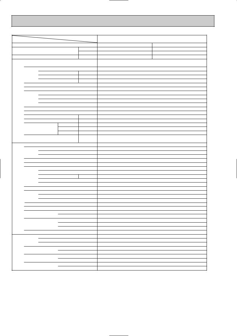
5 
 SPECIFICATIONS
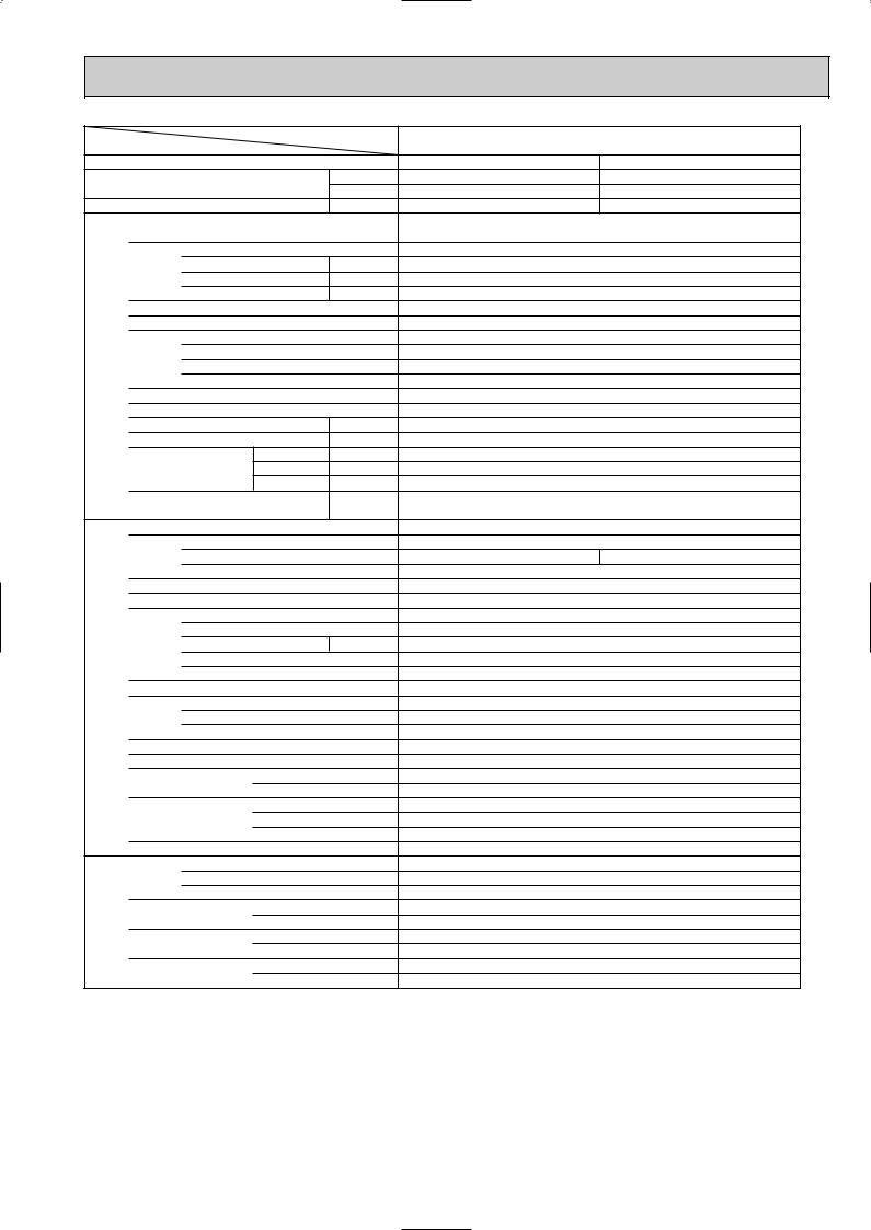
1.Heat pump type
Item |
|
|
Service Ref. |
||
|
|
|
|
||
Function |
|
|
|
|
|
Capacity |
|
|
Btu/h |
||
|
|
W |
|||
|
|
|
|
||
Total input |
|
|
k W |
||
|
Service Ref. |
|
|
||
|
Power supply (phase, cycle,voltage) |
|
|||
|
|
Input |
|
k W |
|
|
|
Running current |
A |
||
|
|
Starting current |
A |
||
|
External finish (Panel) |
|
|
||
|
Heat exchanger |
|
|
||
unit |
|
Fan (drive) o No. |
|
||
Fan |
Fan motor output |
kW |
|||
Indoor |
Airflow (Lo-Mi2-Mi1-Hi) |
K/ min (CFM) |
|||
|
|||||
|
|
||||
|
|
External static pressure |
Pa (mmAq) |
||
|
Booster heater |
|
kW |
||
|
Operation control & Thermostat |
|
|||
|
Sound level (Lo-Mi2-Mi1-Hi) |
dB |
|||
|
Unit drain pipe I.D. |
|
mm (in.) |
||
|
|
|
W |
mm (in.) |
|
|
Dimensions |
D |
mm (in.) |
||
|
|
|
H |
mm (in.) |
|
|
Weight |
|
|
kg (lbs.) |
|
|
Service Ref. |
|
|
||
|
Power supply (phase, cycle, voltage) |
|
|||
|
|
Running current |
A |
||
|
|
Starting current |
A |
||
|
External finish |
|
|
||
|
Refrigerant control |
|
|
||
|
Compressor |
|
|
||
|
|
Model |
|
|
|
unit |
|
Motor output |
|
kW |
|
|
Starter type |
|
|
||
|
|
|
|
||
Outdoor |
|
Protection devices |
|
||
Heat exchanger |
|
|
|||
|
|
|
|||
|
|
Fan (drive) o No. |
|
||
|
Fan |
Fan motor output |
kW |
||
|
|
Airflow |
|
K/ min (CFM) |
|
|
Crankcase |
heater |
|
W |
|
|
Defrost method |
|
|
||
|
Sound level |
Cooling |
dB |
||
|
Heating |
dB |
|||
|
|
|
|||
|
|
|
W |
mm (in.) |
|
|
Dimensions |
D |
mm (in.) |
||
|
|
|
H |
mm (in.) |
|
|
Weight |
|
|
kg (lbs.) |
|
|
Refrigerant |
|
|
||
piping |
|
Charge |
|
kg (lbs.) |
|
|
Oil (Model) |
|
L |
||
|
|
|
|||
Refrigerant |
Pipe size O.D. |
Liquid |
mm (in.) |
||
Gas |
mm (in.) |
||||
|
|||||
|
|
|
|||
|
Connection method |
Indoor side |
|
||
|
Outdoor side |
|
|||
|
|
|
|
||
|
Between the indoor & |
Height difference |
|||
|
outdoor units |
Piping length |
|
||
PLA-P3AA.UK |
||
|
|
|
Cooling |
|
Heating |
26,600 |
|
31,700 |
7,800 |
|
9,300 |
3.51 |
|
3.65 |
PLA-P3AA.UK |
|
|
Single phase, 50Hz, 220-230-240V |
||
0.17 |
|
0.17 |
0.81 |
|
0.81 |
1.0 |
|
1.0 |
Munsell 0.70Y 8.59/0.97 |
||
Plate fin coil |
|
|
Turbo fan (direct) o 1 |
||
0.070 |
|
|
15-16-18-20 (530-565-635-705) |
||
0 (direct blow) |
|
|
— |
|
|
Remote controller & built-in |
||
28-30-32-34 |
|
|
32 (1-1/4) |
|
|
UNIT : 840 (33-1/16) |
PANEL : 950 (37-3/8) |
|
UNIT : 840 (33-1/16) |
PANEL : 950 (37-3/8) |
|
UNIT : 258 (10-1/2) |
PANEL : 30 (1-3/16) |
|
UNIT : 24 (53) |
PANEL: 5 (11) |
|
PUH-P3VGA / PUH-3YGA
Single phase, 50Hz, 220-230-240V / 3 phase, 50Hz, 380-400-415V (4wires)
14.64/5.46 |
15.43/5.76 |
93/41 Munsell 5Y 8/1 Linear expansion valve Hermetic
NE52VNJM / NE52YDJM 2.5
Line start
Internal thermostat, HP switch, Discharge thermo. / Thermal relay Discharge thermo, HP switch, Anti-phase protector. Plate fin coil
Propeller (direct) o 1 0.070
50(1,770)
38
Reverse cycle 49
51
900 (35-7/16)
330+20 (13+3/4)
855 (33-5/8)
82 (181) R407C
3.7(8.2)
1.6(MEL56) 9.52 (3/8)
15.88 (5/8) Flared Flared Max. 50m Max. 50m
NOTE: 1. Rating conditions (ISO T1) |
|
|
|
Cooling |
Indoor : D.B. 27: (80˚F) W.B. 19: (66˚F) |
Outdoor : D.B. 35: (95˚F) |
W.B. 24: (75˚F) |
Heating |
Indoor : D.B. 20: (68˚F) |
Outdoor : D.B. 7: (45˚F) |
W.B. 6: (43˚F) |
Refrigerant piping length (one way) : 5m (16ft.) |
|
|
|
||||
2. Guaranteed operating range |
|
|
3. Above data based on indicated voltage |
||||
|
|
|
Indoor |
Outdoor |
Indoor unit |
Single phase 240V 50Hz |
|
|
Cooling |
Upper limit |
D.B. 35˚C, |
W.B. 22.5˚C |
D.B. 46˚C |
Outdoor unit |
Single phase 240V 50Hz / 3 phase 415V 50Hz |
|
Lower limit |
D.B. 19˚C, |
W.B. 15˚C |
D.B. -5˚C |
|
|
|
|
|
|
|
||||
|
Heating |
Upper limit |
D.B. 28˚C |
|
D.B. 24˚C, W.B. 18˚C |
|
|
|
Lower limit |
D.B. 17˚C |
|
D.B. -11˚C, W.B. -12˚C |
|
|
|
|
|
|
|
|
|||
11
Item |
|
|
Service Ref. |
||
|
|
|
|
||
Function |
|
|
|
|
|
Capacity |
|
|
Btu/h |
||
|
|
W |
|||
|
|
|
|
|
|
Total input |
|
|
k W |
||
|
|
Service Ref. |
|
|
|
|
|
Power supply (phase, cycle,voltage) |
|
||
|
|
|
Input |
|
k W |
|
|
|
Running current |
A |
|
|
|
|
Starting current |
A |
|
|
|
External finish (Panel) |
|
|
|
|
|
Heat exchanger |
|
|
|
unit |
|
|
Fan (drive) o No. |
|
|
|
Fan |
Fan motor output |
kW |
||
Indoor |
|
Airflow (Lo-Mi2-Mi1-Hi) |
K/ min (CFM) |
||
|
|
||||
|
|
|
|||
|
|
|
External static pressure |
Pa (mmAq) |
|
|
|
Booster heater |
|
kW |
|
|
|
Operation control & Thermostat |
|
||
|
|
Sound level (Lo-Mi2-Mi1-Hi) |
dB |
||
|
|
Unit drain pipe I.D. |
|
mm (in.) |
|
|
|
|
|
W |
mm (in.) |
|
|
Dimensions |
D |
mm (in.) |
|
|
|
|
|
H |
mm (in.) |
|
|
Weight |
|
|
kg (lbs.) |
|
|
Service Ref. |
|
|
|
|
|
Power supply (phase, cycle, voltage) |
|
||
|
|
|
Running current |
A |
|
|
|
|
Starting current |
A |
|
|
|
External finish |
|
|
|
|
|
Refrigerant control |
|
|
|
|
|
Compressor |
|
|
|
|
|
|
Model |
|
|
unit |
|
|
Motor output |
|
kW |
|
|
Starter type |
|
|
|
|
|
|
|
|
|
Outdoor |
|
|
Protection devices |
|
|
|
Heat exchanger |
|
|
||
|
|
|
|
||
|
|
|
Fan (drive) o No. |
|
|
|
|
Fan |
Fan motor output |
kW |
|
|
|
|
Airflow |
|
K/ min (CFM) |
|
|
Crankcase heater |
|
W |
|
|
|
Defrost method |
|
|
|
|
|
Sound level |
Cooling |
dB |
|
|
|
Heating |
dB |
||
|
|
|
|
||
|
|
|
|
W |
mm (in.) |
|
|
Dimensions |
D |
mm (in.) |
|
|
|
|
|
H |
mm (in.) |
|
|
Weight |
|
|
kg (lbs.) |
|
|
Refrigerant |
|
|
|
piping |
|
|
Charge |
|
kg (lbs.) |
|
|
Oil (Model) |
|
L |
|
|
|
|
|
||
Refrigerant |
|
Pipe size O.D. |
Liquid |
mm (in.) |
|
|
Gas |
mm (in.) |
|||
|
|
||||
|
|
|
|
||
|
|
Connection method |
Indoor side |
|
|
|
|
Outdoor side |
|
||
|
|
|
|
|
|
|
|
Between the indoor & |
Height difference |
||
|
|
outdoor units |
Piping length |
|
|
|
|
|
|
|
|
|
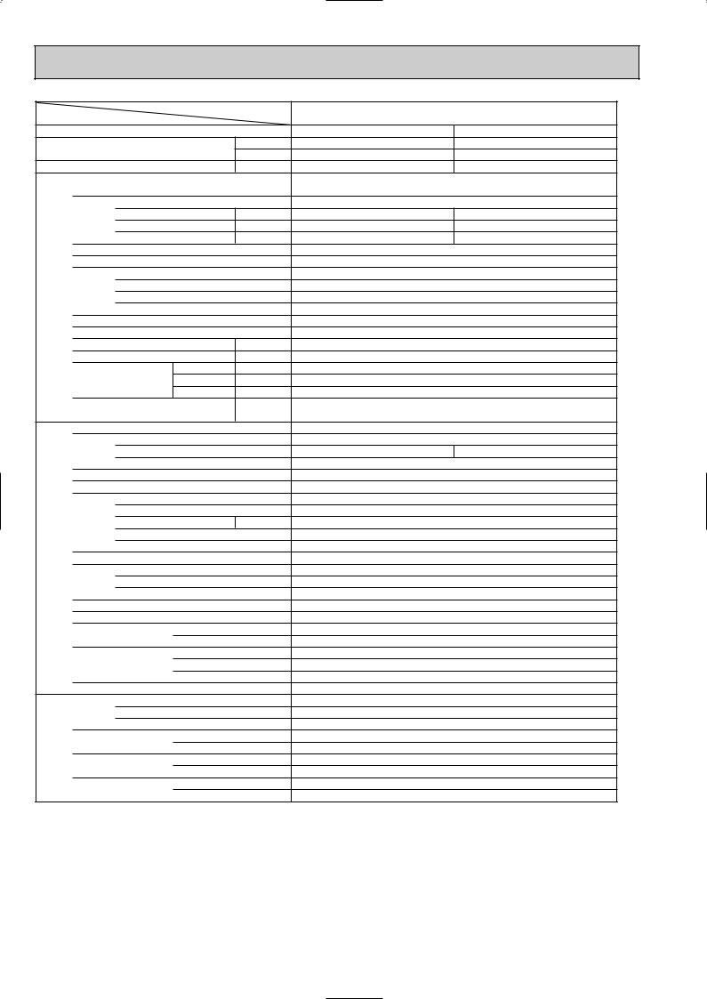
PLA-P4AA.UK |
Cooling |
Heating |
33,100 |
36,200 |
9,700 |
10,600 |
3.62 |
3.80 |
PLA-P4AA.UK |
||
Single phase, 50Hz, 220-230-240V |
||
0.26 |
|
0.26 |
1.25 |
|
1.25 |
2.0 |
|
2.0 |
Munsell 0.70Y 8.59/0.97 |
||
Plate fin coil |
||
Turbo fan (direct) o 1 |
||
0.120 |
|
|
20-23-26-28 (705-810-920-990) |
||
0 (direct blow) |
||
— |
|
|
Remote controller & built-in |
||
33-36-39-41 |
||
32 (1-1/4) |
||
UNIT : 840 (33-1/16) |
PANEL : 950 (37-3/8) |
|
UNIT : 840 (33-1/16) |
PANEL : 950 (37-3/8) |
|
UNIT : 298 (11-3/4) |
PANEL : 30 (1-3/16) |
|
UNIT : 30 (66) |
PANEL : 5 (11) |
|
|
PUH-P4YGA |
|
3 phase, 50Hz, 380-400-415V (4wires) |
||
5.49 |
|
5.79 |
|
45 |
|
|
Munsell 5Y 8/1 |
|
|
Linear expansion valve |
|
|
Hermetic |
|
|
NE56YDJM |
|
|
2.7 |
|
|
Line start |
|
Anti-phase protector, Thermal relay, Discharge thermo, HP switch
Plate fin coil
Propeller (direct) o 2
0.070+0.070
85(3,000)
38
Reverse cycle
51
53
900 (35-7/16)
330+20 (13+3/4)
1,260 (49-5/8)
96 (212)
R407C
4.0(8.8)
1.6(MEL56) 9.52 (3/8)
19.05 (3/4)
Flared
Flared
Max. 50m
Max. 50m
NOTE: 1. Rating conditions (ISO T1) |
|
|
|
Cooling |
Indoor : D.B. 27: (80˚F) W.B. 19: (66˚F) |
Outdoor : D.B. 35: (95˚F) |
W.B. 24: (75˚F) |
Heating |
Indoor : D.B. 20: (68˚F) |
Outdoor : D.B. 7: (45˚F) |
W.B. 6: (43˚F) |
Refrigerant piping length (one way) : 5m (16ft.) |
|
|
|
||||
2. Guaranteed operating range |
|
|
3. Above data based on indicated voltage |
||||
|
|
|
|
|
|
Indoor unit |
Single phase 240V 50Hz |
|
|
|
Indoor |
Outdoor |
|||
|
|
|
Outdoor unit |
3 phase 415V 50Hz |
|||
|
Cooling |
Upper limit |
D.B. 35˚C, |
W.B. 22.5˚C |
D.B. 46˚C |
||
|
|
|
|||||
|
Lower limit |
D.B. 19˚C, |
W.B. 15˚C |
D.B. -5˚C |
|
|
|
|
|
|
|
||||
|
Heating |
Upper limit |
D.B. 28˚C |
|
D.B. 24˚C, W.B. 18˚C |
|
|
|
Lower limit |
D.B. 17˚C |
|
D.B. -11˚C, W.B. -12˚C |
|
|
|
|
|
|
|
|
|||
12
Item |
|
|
Service Ref. |
||
|
|
|
|
||
Function |
|
|
|
|
|
Capacity |
|
|
Btu/h |
||
|
|
W |
|||
|
|
|
|
|
|
Total input |
|
|
k W |
||
|
|
Service Ref. |
|
|
|
|
|
Power supply (phase, cycle,voltage) |
|
||
|
|
|
Input |
|
k W |
|
|
|
Running current |
A |
|
|
|
|
Starting current |
A |
|
|
|
External finish (Panel) |
|
|
|
|
|
Heat exchanger |
|
|
|
unit |
|
|
Fan (drive) o No. |
|
|
|
Fan |
Fan motor output |
kW |
||
Indoor |
|
Airflow (Lo-Mi2-Mi1-Hi) |
K/ min (CFM) |
||
|
|
||||
|
|
|
|||
|
|
|
External static pressure |
Pa (mmAq) |
|
|
|
Booster heater |
|
kW |
|
|
|
Operation control & Thermostat |
|
||
|
|
Sound level (Lo-Mi2-Mi1-Hi) |
dB |
||
|
|
Unit drain pipe I.D. |
|
mm (in.) |
|
|
|
|
|
W |
mm (in.) |
|
|
Dimensions |
D |
mm (in.) |
|
|
|
|
|
H |
mm (in.) |
|
|
Weight |
|
|
kg (lbs.) |
|
|
Service Ref. |
|
|
|
|
|
Power supply (phase, cycle, voltage) |
|
||
|
|
|
Running current |
A |
|
|
|
|
Starting current |
A |
|
|
|
External finish |
|
|
|
|
|
Refrigerant control |
|
|
|
|
|
Compressor |
|
|
|
|
|
|
Model |
|
|
unit |
|
|
Motor output |
|
kW |
|
|
Starter type |
|
|
|
|
|
|
|
|
|
Outdoor |
|
|
Protection devices |
|
|
|
Heat exchanger |
|
|
||
|
|
|
|
||
|
|
|
Fan (drive) o No. |
|
|
|
|
Fan |
Fan motor output |
kW |
|
|
|
|
Airflow |
|
K/ min (CFM) |
|
|
Crankcase heater |
|
W |
|
|
|
Defrost method |
|
|
|
|
|
Sound level |
Cooling |
dB |
|
|
|
Heating |
dB |
||
|
|
|
|
||
|
|
|
|
W |
mm (in.) |
|
|
Dimensions |
D |
mm (in.) |
|
|
|
|
|
H |
mm (in.) |
|
|
Weight |
|
|
kg (lbs.) |
|
|
Refrigerant |
|
|
|
piping |
|
|
Charge |
|
kg (lbs.) |
|
|
Oil (Model) |
|
L |
|
|
|
|
|
||
Refrigerant |
|
Pipe size O.D. |
Liquid |
mm (in.) |
|
|
Gas |
mm (in.) |
|||
|
|
||||
|
|
|
|
||
|
|
Connection method |
Indoor side |
|
|
|
|
Outdoor side |
|
||
|
|
|
|
|
|
|
|
Between the indoor & |
Height difference |
||
|
|
outdoor units |
Piping length |
|
|
|
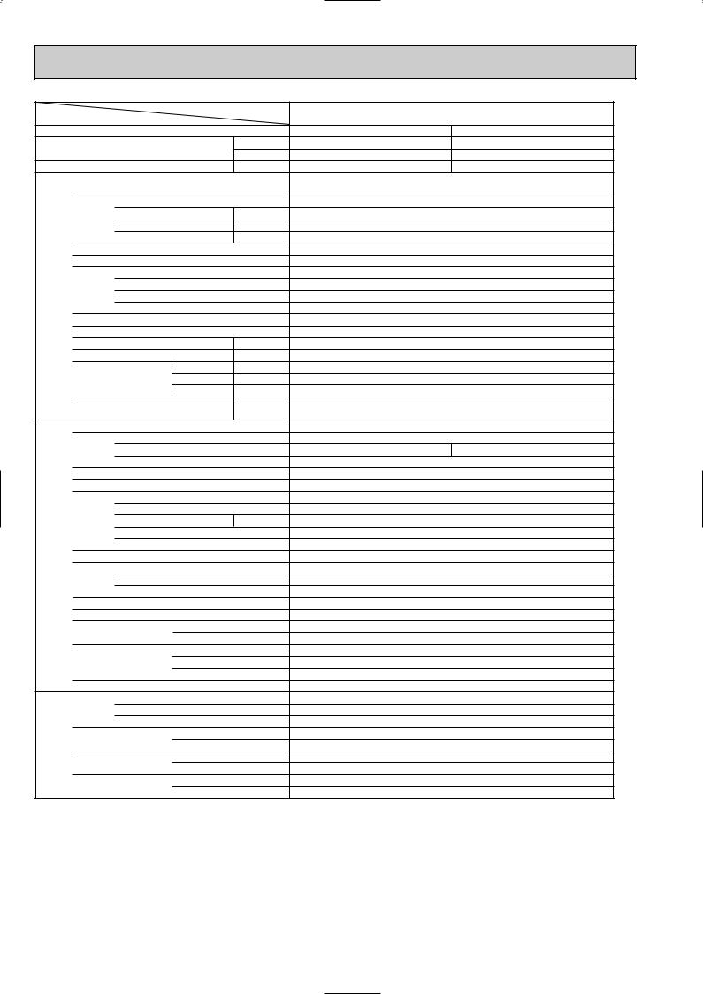
PLA-P5AA.UK |
Cooling |
Heating |
43,700 |
54,600 |
12,800 |
16,000 |
5.55 |
5.93 |
|
PLA-P5AA.UK |
|
|
Single phase, 50Hz, 220-230-240V |
|
0.30 |
|
0.30 |
1.43 |
|
1.43 |
2.0 |
|
2.0 |
|
Munsell 0.70Y 8.59/0.97 |
|
|
Plate fin coil |
|
|
Turbo fan (direct) o 1 |
|
|
0.120 |
|
|
22-25-28-30 (775-880-990-1,060) |
|
|
0 (direct blow) |
|
|
|
— |
Remote controller & built-in
35-38-41-43
32 (1-1/4) |
|
UNIT : 840 (33-1/16) |
PANEL : 950 (37-3/8) |
UNIT : 840 (33-1/16) |
PANEL : 950 (37-3/8) |
UNIT : 298 (11-3/4) |
PANEL : 30 (1-3/16) |
UNIT : 30 (66) |
PANEL : 5 (11) |
|
PUH-P5YGA |
3 phase, 50Hz, 380-400-415V (4wires) |
|
8.39 |
8.74 |
|
79 |
Munsell 5Y 8/1
Linear expansion valve
Hermetic
HE86YAA
4.3
Line start
Internal thermostat, Anti-phase protector, Thermal relay, HP switch, LP switch, Discharge thermo.
Plate fin coil
Propeller (direct) o 2
0.075+0.075
95(3,360)
38
Reverse cycle
53
55
1,050 (41-5/16)
330+20 (13+3/4)
1,260 (49-5/8)
122 (269)
R407C
5.8(12.8)
2.0(MEL32)
9.52(3/8)
19.05(3/4) Flared Flared
Max. 50m
Max. 50m
NOTE: 1. Rating conditions (ISO T1) |
|
|
|
Cooling : |
Indoor: D.B. 27: (80˚F) W.B. 19 : (66˚F) |
Outdoor: D.B. 35: (95˚F) |
W.B. 24 : (75˚F) |
Heating : |
Indoor: D.B. 20: (68˚F) |
Outdoor: D.B. 7: (45˚F) |
W.B. 6 : (43˚F) |
|
Refrigerant piping length (one way) : 5m (16ft.) |
|
|
|
||
2. Guaranteed operating range |
|
3. Above data based on indicated voltage |
||||
|
|
|
|
|
Indoor unit |
Single phase 240V 50Hz |
|
|
|
Indoor |
Outdoor |
||
|
Cooling |
Upper limit |
D.B. 35:, W.B. 22.5: |
D.B. 46: |
Outdoor unit |
3 phase 415V 50Hz |
|
|
|
||||
|
Lower limit |
D.B. 19 :, W.B. 15: |
D.B. -5: |
|
|
|
|
|
|
|
|||
|
Heating |
Upper limit |
D.B. 28: |
D.B. 24 :, W.B. 18: |
|
|
|
Lower limit |
D.B. 17: |
D.B. -11:, W.B. -12: |
|
|
|
|
|
|
|
|||
13
Item |
|
|
Service Ref. |
||
|
|
|
|
||
Function |
|
|
|
|
|
Capacity |
|
|
Btu/h |
||
|
|
W |
|||
|
|
|
|
|
|
Total input |
|
|
k W |
||
|
|
Service Ref. |
|
|
|
|
|
Power supply (phase, cycle,voltage) |
|
||
|
|
|
Input |
|
k W |
|
|
|
Running current |
A |
|
|
|
|
Starting current |
A |
|
|
|
External finish (Panel) |
|
|
|
|
|
Heat exchanger |
|
|
|
unit |
|
|
Fan (drive) o No. |
|
|
|
Fan |
Fan motor output |
kW |
||
Indoor |
|
Airflow (Lo-Mi2-Mi1-Hi) |
K/ min (CFM) |
||
|
|
||||
|
|
|
|||
|
|
|
External static pressure |
Pa (mmAq) |
|
|
|
Booster heater |
|
kW |
|
|
|
Operation control & Thermostat |
|
||
|
|
Sound level (Lo-Mi2-Mi1-Hi) |
dB |
||
|
|
Unit drain pipe I.D. |
|
mm (in.) |
|
|
|
|
|
W |
mm (in.) |
|
|
Dimensions |
D |
mm (in.) |
|
|
|
|
|
H |
mm (in.) |
|
|
Weight |
|
|
kg (lbs.) |
|
|
Service Ref. |
|
|
|
|
|
Power supply (phase, cycle, voltage) |
|
||
|
|
|
Running current |
A |
|
|
|
|
Starting current |
A |
|
|
|
External finish |
|
|
|
|
|
Refrigerant control |
|
|
|
|
|
Compressor |
|
|
|
|
|
|
Model |
|
|
unit |
|
|
Motor output |
|
kW |
|
|
Starter type |
|
|
|
|
|
|
|
|
|
Outdoor |
|
|
Protection devices |
|
|
|
Heat exchanger |
|
|
||
|
|
|
|
||
|
|
|
Fan (drive) o No. |
|
|
|
|
Fan |
Fan motor output |
kW |
|
|
|
|
Airflow |
|
K/ min (CFM) |
|
|
Crankcase heater |
|
W |
|
|
|
Defrost method |
|
|
|
|
|
Sound level |
Cooling |
dB |
|
|
|
Heating |
dB |
||
|
|
|
|
||
|
|
|
|
W |
mm (in.) |
|
|
Dimensions |
D |
mm (in.) |
|
|
|
|
|
H |
mm (in.) |
|
|
Weight |
|
|
kg (lbs.) |
|
|
Refrigerant |
|
|
|
piping |
|
|
Charge |
|
kg (lbs.) |
|
|
Oil (Model) |
|
L |
|
|
|
|
|
||
Refrigerant |
|
Pipe size O.D. |
Liquid |
mm (in.) |
|
|
Gas |
mm (in.) |
|||
|
|
||||
|
|
|
|
||
|
|
Connection method |
Indoor side |
|
|
|
|
Outdoor side |
|
||
|
|
|
|
|
|
|
|
Between the indoor & |
Height difference |
||
|
|
outdoor units |
Piping length |
|
|
|
PLA-P6AA.UK |
Cooling |
Heating |
48,000 |
57,300 |
14,300 |
16,800 |
6.70 |
6.77 |
PLA-P6AA.UK
Single phase, 50Hz, 220-230-240V (4wires)
0.34 |
0.34 |
1.64 |
1.64 |
2.0 |
2.0 |
Munsell 0.70Y 8.59/0.97
Plate fin coil
Turbo fan (direct) o 1 0.120
22-25-28-30 (775-880-990-1,060)
0 (direct blow)
—
Remote controller & built-in
37-40-43-45
32 (1-1/4) |
|
UNIT : 840 (33-1/16) |
PANEL : 950 (37-3/8) |
UNIT : 840 (33-1/16) |
PANEL : 950 (37-3/8) |
UNIT : 298 (11-3/4) |
PANEL : 30 (1-3/16) |
UNIT : 32 (71) |
PANEL : 5 (11) |
|
PUH-P6YGA |
3 phase, 50Hz, 380-400-415V (4wires) |
|
10.17 |
10.28 |
84
Munsell 5Y 8/1
Linear expansion valve
Hermetic
HE101YAA
5.1
Line start
Internal thermostat, Anit-phase protector, Thermal relay, HP switch, LP switch, Discharge thermo.
Plate fin coil
Propeller (direct) o 2
0.075+0.075
100(3,530)
38
Reverse cycle
55
57
1,050 (41-5/16)
330+20(13+3/4)
1,260 (49-5/8)
122 (269)
R407C
5.8(12.8)
2.0(MEL32)
9.52(3/8)
19.05(3/4) Flared Flared
Max. 50m
Max. 50m
NOTE: 1. Rating conditions (ISO T1) |
|
|
|
Cooling : |
Indoor: D.B. 27: (80˚F) W.B. 19: (66˚F) |
Outdoor: D.B. 35: (95˚F) |
W.B. 24: (75˚F) |
Heating : |
Indoor: D.B. 20: (68˚F) |
Outdoor: D.B. 7: (45˚F) |
W.B. 6 : (43˚F) |
|
Refrigerant piping length (one way) : 5m (16ft.) |
|
|
|
||
2. Guaranteed operating range |
|
3. Above data based on indicated voltage |
||||
|
|
|
|
|
||
|
|
|
Indoor |
Outdoor |
Indoor unit |
Single phase 240V 50Hz |
|
Cooling |
Upper limit |
D.B. 35:, W.B. 22.5: |
D.B. 46: |
Outdoor unit |
3 phase 415V 50Hz |
|
Lower limit |
D.B. 19 :, W.B. 15: |
D.B. -5: |
|||
|
|
|
|
|||
|
Heating |
Upper limit |
D.B. 28: |
D.B. 24 :, W.B. 18: |
|
|
|
Lower limit |
D.B. 17: |
D.B. -11:, W.B. -12: |
|
|
|
|
|
|
|
|||
14

Item |
|
|
Service Ref. |
||
|
|
|
|
||
Function |
|
|
|
|
|
Capacity |
|
|
Btu/h |
||
|
|
W |
|||
|
|
|
|
||
Total input |
|
|
k W |
||
|
Service Ref. |
|
|
||
|
Power supply (phase, cycle,voltage) |
|
|||
|
|
Input |
|
k W |
|
|
|
Running current |
A |
||
|
|
Starting current |
A |
||
|
External finish (Panel) |
|
|
||
|
Heat exchanger |
|
|
||
unit |
|
Fan (drive) o No. |
|
||
Fan |
Fan motor output |
kW |
|||
Indoor |
Airflow (Lo-Mi2-Mi1-Hi) |
K/ min (CFM) |
|||
|
|||||
|
|
||||
|
|
External static pressure |
Pa (mmAq) |
||
|
Booster heater |
|
kW |
||
|
Operation control & Thermostat |
|
|||
|
Sound level (Lo-Mi2-Mi1-Hi) |
dB |
|||
|
Unit drain pipe I.D. |
|
mm (in.) |
||
|
|
|
W |
mm (in.) |
|
|
Dimensions |
D |
mm (in.) |
||
|
|
|
H |
mm (in.) |
|
|
Weight |
|
|
kg (lbs.) |
|
|
Service Ref. |
|
|
||
|
Power supply (phase, cycle, voltage) |
|
|||
|
|
Running current |
A |
||
|
|
Starting current |
A |
||
|
External finish |
|
|
||
|
Refrigerant control |
|
|
||
|
Compressor |
|
|
||
|
|
Model |
|
|
|
unit |
|
Motor output |
|
kW |
|
|
Starter type |
|
|
||
|
|
|
|
||
Outdoor |
|
Protection devices |
|
||
Heat exchanger |
|
|
|||
|
|
|
|||
|
|
Fan (drive) o No. |
|
||
|
Fan |
Fan motor output |
kW |
||
|
|
Airflow |
|
K/ min (CFM) |
|
|
Crankcase |
heater |
|
W |
|
|
Defrost method |
|
|
||
|
Sound level |
Cooling |
dB |
||
|
Heating |
dB |
|||
|
|
|
|||
|
|
|
W |
mm (in.) |
|
|
Dimensions |
D |
mm (in.) |
||
|
|
|
H |
mm (in.) |
|
|
Weight |
|
|
kg (lbs.) |
|
|
Refrigerant |
|
|
||
piping |
|
Charge |
|
kg (lbs.) |
|
|
Oil (Model) |
|
L |
||
|
|
|
|||
Refrigerant |
Pipe size O.D. |
Liquid |
mm (in.) |
||
Gas |
mm (in.) |
||||
|
|||||
|
|
|
|||
|
Connection method |
Indoor side |
|
||
|
Outdoor side |
|
|||
|
|
|
|
||
|
Between the indoor & |
Height difference |
|||
|
outdoor units |
Piping length |
|
||
PLA-P3AA.UK / PLA-P3AA1.UK
Cooling |
|
Heating |
26,600 |
|
31,700 |
7,800 |
|
9,300 |
3.44 |
|
3.50 |
PLA-P3AA.UK / PLA-P3AA1.UK |
||
Single phase, 50Hz, 220-230-240V |
||
0.17 |
|
0.17 |
0.81 |
|
0.81 |
1.0 |
|
1.0 |
Munsell 0.70Y 8.59/0.97 |
||
Plate fin coil |
|
|
Turbo fan (direct) o 1 |
||
0.070 |
|
|
15-16-18-20 (530-565-635-705) |
||
0 (direct blow) |
|
|
— |
|
|
Remote controller & built-in |
||
28-30-32-34 |
|
|
32 (1-1/4) |
|
|
UNIT : 840 (33-1/16) |
PANEL : 950 (37-3/8) |
|
UNIT : 840 (33-1/16) |
PANEL : 950 (37-3/8) |
|
UNIT : 258 (10-1/2) |
PANEL : 30 (1-3/16) |
|
UNIT : 24 (53) |
PANEL: 5 (11) |
|
PUH-P3VGAA.UK / PUH-P3YGAA.UK
Single phase, 50Hz, 220-230-240V / 3 phase, 50Hz, 380-400-415V (4wires)
14.81/5.29 |
15.76/5.63 |
93/47 Munsell 5Y 7/1 Linear expansion valve Hermetic
NE52VNJMT / NE52YDKMT 2.5
Line start
Internal thermostat, HP switch, Discharge thermo. / Thermal relay , HP switch, Discharge thermo. Plate fin coil
Propeller (direct) o 1 0.070
50(1,770)
38
Reverse cycle 49
51
900 (35-7/16)
330+20 (13+3/4)
855 (33-5/8)
82 (181) R407C
3.3(7.3)
1.3(Ester) MEL56 9.52 (3/8)
15.88 (5/8) Flared Flared Max. 50m Max. 50m
NOTE: 1. Rating conditions (ISO T1) |
|
|
|
Cooling |
Indoor : D.B. 27: (80˚F) W.B. 19: (66˚F) |
Outdoor : D.B. 35: (95˚F) |
W.B. 24: (75˚F) |
Heating |
Indoor : D.B. 20: (68˚F) |
Outdoor : D.B. 7: (45˚F) |
W.B. 6: (43˚F) |
Refrigerant piping length (one way) : 5m (16ft.) |
|
|
|
||||
2. Guaranteed operating range |
|
|
3. Above data based on indicated voltage |
||||
|
|
|
Indoor |
Outdoor |
Indoor unit |
Single phase 240V 50Hz |
|
|
Cooling |
Upper limit |
D.B. 35˚C, |
W.B. 22.5˚C |
D.B. 46˚C |
Outdoor unit |
Single phase 240V 50Hz / 3 phase 415V 50Hz |
|
|
|
|||||
|
Lower limit |
D.B. 19˚C, |
W.B. 15˚C |
D.B. -5˚C |
|
|
|
|
|
|
|
||||
|
Heating |
Upper limit |
D.B. 28˚C |
|
D.B. 24˚C, W.B. 18˚C |
|
|
|
Lower limit |
D.B. 17˚C |
|
D.B. -11˚C, W.B. -12˚C |
|
|
|
|
|
|
|
|
|||
15
Item |
|
|
Service Ref. |
||
|
|
|
|
||
Function |
|
|
|
|
|
Capacity |
|
|
Btu/h |
||
|
|
W |
|||
|
|
|
|
|
|
Total input |
|
|
k W |
||
|
|
Service Ref. |
|
|
|
|
|
Power supply (phase, cycle,voltage) |
|
||
|
|
|
Input |
|
k W |
|
|
|
Running current |
A |
|
|
|
|
Starting current |
A |
|
|
|
External finish (Panel) |
|
|
|
|
|
Heat exchanger |
|
|
|
unit |
|
|
Fan (drive) o No. |
|
|
|
Fan |
Fan motor output |
kW |
||
Indoor |
|
Airflow (Lo-Mi2-Mi1-Hi) |
K/ min (CFM) |
||
|
|
||||
|
|
|
|||
|
|
|
External static pressure |
Pa (mmAq) |
|
|
|
Booster heater |
|
kW |
|
|
|
Operation control & Thermostat |
|
||
|
|
Sound level (Lo-Mi2-Mi1-Hi) |
dB |
||
|
|
Unit drain pipe I.D. |
|
mm (in.) |
|
|
|
|
|
W |
mm (in.) |
|
|
Dimensions |
D |
mm (in.) |
|
|
|
|
|
H |
mm (in.) |
|
|
Weight |
|
|
kg (lbs.) |
|
|
Service Ref. |
|
|
|
|
|
Power supply (phase, cycle, voltage) |
|
||
|
|
|
Running current |
A |
|
|
|
|
Starting current |
A |
|
|
|
External finish |
|
|
|
|
|
Refrigerant control |
|
|
|
|
|
Compressor |
|
|
|
|
|
|
Model |
|
|
unit |
|
|
Motor output |
|
kW |
|
|
Starter type |
|
|
|
|
|
|
|
|
|
Outdoor |
|
|
Protection devices |
|
|
|
Heat exchanger |
|
|
||
|
|
|
|
||
|
|
|
Fan (drive) o No. |
|
|
|
|
Fan |
Fan motor output |
kW |
|
|
|
|
Airflow |
|
K/ min (CFM) |
|
|
Crankcase heater |
|
W |
|
|
|
Defrost method |
|
|
|
|
|
Sound level |
Cooling |
dB |
|
|
|
Heating |
dB |
||
|
|
|
|
||
|
|
|
|
W |
mm (in.) |
|
|
Dimensions |
D |
mm (in.) |
|
|
|
|
|
H |
mm (in.) |
|
|
Weight |
|
|
kg (lbs.) |
|
|
Refrigerant |
|
|
|
piping |
|
|
Charge |
|
kg (lbs.) |
|
|
Oil (Model) |
|
L |
|
|
|
|
|
||
Refrigerant |
|
Pipe size O.D. |
Liquid |
mm (in.) |
|
|
Gas |
mm (in.) |
|||
|
|
||||
|
|
|
|
||
|
|
Connection method |
Indoor side |
|
|
|
|
Outdoor side |
|
||
|
|
|
|
|
|
|
|
Between the indoor & |
Height difference |
||
|
|
outdoor units |
Piping length |
|
|
PLA-P4AA.UK / PLA-P4AA1.UK
Cooling |
Heating |
33,100 |
36,200 |
9,700 |
10,600 |
3.69 |
3.93 |
PLA-P4AA.UK / PLA-P4AA1.UK |
|||
Single phase, 50Hz, 220-230-240V |
|||
0.26 |
|
|
0.26 |
1.25 |
|
|
1.25 |
2.0 |
|
|
2.0 |
Munsell 0.70Y 8.59/0.97 |
|
||
Plate fin coil |
|
||
Turbo fan (direct) o 1 |
|
||
0.120 |
|
|
|
20-23-26-28 (705-810-920-990) |
|||
0 (direct blow) |
|
||
— |
|
|
|
Remote controller & built-in |
|||
33-36-39-41 |
|
||
32 (1-1/4) |
|
||
UNIT : 840 (33-1/16) |
PANEL : |
950 (37-3/8) |
|
UNIT : 840 (33-1/16) |
PANEL : |
950 (37-3/8) |
|
UNIT : 298 (11-3/4) |
PANEL : |
30 (1-3/16) |
|
UNIT : 30 (66) |
PANEL : |
5 (11) |
|
PUH-P4VGAA.UK / PUH-P4YGAA.UK
Single phase, 50Hz, 220-230-240V/ 3 phase, 50Hz, 380-400-415V (4wires)
15.71/ 5.55 |
16.58/ 5.86 |
99/49
Munsell 5Y 7/1
Linear expansion valve
Hermetic
NE56VNJMT/ NE56YDKMT
2.7
Line start
Intemal thermostat,HP switch, Discharge thermo. / Thermal relay, HP swich, Dischage thermo.
Plate fin coil
Propeller (direct) o 2
0.070+0.070
85(3,000)
38
Reverse cycle
51
53
900 (35-7/16)
330+20 (13+3/4)
1,260 (49-5/8)
96 (212)
R407C
4.0(8.8)
1.3(MEL56) 9.52 (3/8)
19.05 (3/4)
Flared
Flared
Max. 50m
Max. 50m
NOTE: 1. Rating conditions (ISO T1) |
|
|
|
Cooling |
Indoor : D.B. 27: (80˚F) W.B. 19: (66˚F) |
Outdoor : D.B. 35: (95˚F) |
W.B. 24: (75˚F) |
Heating |
Indoor : D.B. 20: (68˚F) |
Outdoor : D.B. 7: (45˚F) |
W.B. 6: (43˚F) |
Refrigerant piping length (one way) : 5m (16ft.) |
|
|
|
||||
2. Guaranteed operating range |
|
|
3. Above data based on indicated voltage |
||||
|
|
|
|
|
|
Indoor unit |
Single phase 240V 50Hz |
|
|
|
Indoor |
Outdoor |
|||
|
|
|
Outdoor unit |
3 phase 415V 50Hz |
|||
|
Cooling |
Upper limit |
D.B. 35˚C, |
W.B. 22.5˚C |
D.B. 46˚C |
||
|
|
|
|||||
|
Lower limit |
D.B. 19˚C, |
W.B. 15˚C |
D.B. -5˚C |
|
|
|
|
|
|
|
||||
|
Heating |
Upper limit |
D.B. 28˚C |
|
D.B. 24˚C, W.B. 18˚C |
|
|
|
Lower limit |
D.B. 17˚C |
|
D.B. -11˚C, W.B. -12˚C |
|
|
|
|
|
|
|
|
|||
16

Item |
|
|
Service Ref. |
||
|
|
|
|
||
Function |
|
|
|
|
|
Capacity |
|
|
Btu/h |
||
|
|
W |
|||
|
|
|
|
|
|
Total input |
|
|
k W |
||
|
|
Service Ref. |
|
|
|
|
|
Power supply (phase, cycle,voltage) |
|
||
|
|
|
Input |
|
k W |
|
|
|
Running current |
A |
|
|
|
|
Starting current |
A |
|
|
|
External finish (Panel) |
|
|
|
|
|
Heat exchanger |
|
|
|
unit |
|
|
Fan (drive) o No. |
|
|
|
Fan |
Fan motor output |
kW |
||
Indoor |
|
Airflow (Lo-Mi2-Mi1-Hi) |
K/ min (CFM) |
||
|
|
||||
|
|
|
|||
|
|
|
External static pressure |
Pa (mmAq) |
|
|
|
Booster heater |
|
kW |
|
|
|
Operation control & Thermostat |
|
||
|
|
Sound level (Lo-Mi2-Mi1-Hi) |
dB |
||
|
|
Unit drain pipe I.D. |
|
mm (in.) |
|
|
|
|
|
W |
mm (in.) |
|
|
Dimensions |
D |
mm (in.) |
|
|
|
|
|
H |
mm (in.) |
|
|
Weight |
|
|
kg (lbs.) |
|
|
Service Ref. |
|
|
|
|
|
Power supply (phase, cycle, voltage) |
|
||
|
|
|
Running current |
A |
|
|
|
|
Starting current |
A |
|
|
|
External finish |
|
|
|
|
|
Refrigerant control |
|
|
|
|
|
Compressor |
|
|
|
|
|
|
Model |
|
|
unit |
|
|
Motor output |
|
kW |
|
|
Starter type |
|
|
|
|
|
|
|
|
|
Outdoor |
|
|
Protection devices |
|
|
|
Heat exchanger |
|
|
||
|
|
|
|
||
|
|
|
Fan (drive) o No. |
|
|
|
|
Fan |
Fan motor output |
kW |
|
|
|
|
Airflow |
|
K/ min (CFM) |
|
|
Crankcase heater |
|
W |
|
|
|
Defrost method |
|
|
|
|
|
Sound level |
Cooling |
dB |
|
|
|
Heating |
dB |
||
|
|
|
|
||
|
|
|
|
W |
mm (in.) |
|
|
Dimensions |
D |
mm (in.) |
|
|
|
|
|
H |
mm (in.) |
|
|
Weight |
|
|
kg (lbs.) |
|
|
Refrigerant |
|
|
|
piping |
|
|
Charge |
|
kg (lbs.) |
|
|
Oil (Model) |
|
L |
|
|
|
|
|
||
Refrigerant |
|
Pipe size O.D. |
Liquid |
mm (in.) |
|
|
Gas |
mm (in.) |
|||
|
|
||||
|
|
|
|
||
|
|
Connection method |
Indoor side |
|
|
|
|
Outdoor side |
|
||
|
|
|
|
|
|
|
|
Between the indoor & |
Height difference |
||
|
|
outdoor units |
Piping length |
|
|
|
|
|
|
|
|
PLA-P5AA.UK / PLA-P5AA1.UK
Cooling |
Heating |
43,700 |
50,800 |
12,800 |
14,900 |
5.00 |
5.34 |
|
PLA-P5AA.UK / PLA-P5AA1.UK |
|
|
Single phase, 50Hz, 220-230-240V |
|
0.30 |
|
0.30 |
1.43 |
|
1.43 |
2.0 |
|
2.0 |
|
Munsell 0.70Y 8.59/0.97 |
|
|
Plate fin coil |
|
|
Turbo fan (direct) o 1 |
|
|
0.120 |
|
|
22-25-28-30 (775-880-990-1,060) |
|
|
0 (direct blow) |
|
|
|
— |
Remote controller & built-in
35-38-41-43
32 (1-1/4) |
|
UNIT : 840 (33-1/16) |
PANEL : 950 (37-3/8) |
UNIT : 840 (33-1/16) |
PANEL : 950 (37-3/8) |
UNIT : 298 (11-3/4) |
PANEL : 30 (1-3/16) |
UNIT : 30 (66) |
PANEL : 5 (11) |
|
PUH-P5YGAA.UK |
3 phase, 50Hz, 380-400-415V (4wires) |
|
7.60 |
8.15 |
|
65.5 |
Munsell 5Y 7/1
Linear expansion valve
Hermetic
ZR61KCE-TFD
3.5
Line start
Internal thermostat, Thermal relay, HP swich, Discharge thermo.
Plate fin coil
Propeller (direct) o 2
0.070+0.070
95(3,360)
38
Reverse cycle
55
56
1,050 (41-5/16)
330+20 (13+3/4)
1,260 (49-5/8)
122 (269)
R407C
4.6 (10.1)
1.690 (Ester) MMMA-POE
9.52 (3/8)
19.05 (3/4)
Flared
Flared
Max. 50m
Max. 50m
NOTE: 1. Rating conditions (ISO T1) |
|
|
|
Cooling : |
Indoor: D.B. 27: (80˚F) W.B. 19 : (66˚F) |
Outdoor: D.B. 35: (95˚F) |
W.B. 24 : (75˚F) |
Heating : |
Indoor: D.B. 20: (68˚F) |
Outdoor: D.B. 7: (45˚F) |
W.B. 6 : (43˚F) |
|
Refrigerant piping length (one way) : 5m (16ft.) |
|
|
|
||
2. Guaranteed operating range |
|
3. Above data based on indicated voltage |
||||
|
|
|
Indoor |
Outdoor |
Indoor unit |
Single phase 240V 50Hz |
|
Cooling |
Upper limit |
D.B. 35:, W.B. 22.5: |
D.B. 46: |
Outdoor unit |
3 phase 415V 50Hz |
|
Lower limit |
D.B. 19 :, W.B. 15: |
D.B. -5: |
|
|
|
|
|
|
|
|||
|
Heating |
Upper limit |
D.B. 28: |
D.B. 24 :, W.B. 18: |
|
|
|
Lower limit |
D.B. 17: |
D.B. -11:, W.B. -12: |
|
|
|
|
|
|
|
|||
17

Item |
|
|
Service Ref. |
||
|
|
|
|
||
Function |
|
|
|
|
|
Capacity |
|
|
Btu/h |
||
|
|
W |
|||
|
|
|
|
|
|
Total input |
|
|
k W |
||
|
|
Service Ref. |
|
|
|
|
|
Power supply (phase, cycle,voltage) |
|
||
|
|
|
Input |
|
k W |
|
|
|
Running current |
A |
|
|
|
|
Starting current |
A |
|
|
|
External finish (Panel) |
|
|
|
|
|
Heat exchanger |
|
|
|
unit |
|
|
Fan (drive) o No. |
|
|
|
Fan |
Fan motor output |
kW |
||
Indoor |
|
Airflow (Lo-Mi2-Mi1-Hi) |
K/ min (CFM) |
||
|
|
||||
|
|
|
|||
|
|
|
External static pressure |
Pa (mmAq) |
|
|
|
Booster heater |
|
kW |
|
|
|
Operation control & Thermostat |
|
||
|
|
Sound level (Lo-Mi2-Mi1-Hi) |
dB |
||
|
|
Unit drain pipe I.D. |
|
mm (in.) |
|
|
|
|
|
W |
mm (in.) |
|
|
Dimensions |
D |
mm (in.) |
|
|
|
|
|
H |
mm (in.) |
|
|
Weight |
|
|
kg (lbs.) |
|
|
Service Ref. |
|
|
|
|
|
Power supply (phase, cycle, voltage) |
|
||
|
|
|
Running current |
A |
|
|
|
|
Starting current |
A |
|
|
|
External finish |
|
|
|
|
|
Refrigerant control |
|
|
|
|
|
Compressor |
|
|
|
|
|
|
Model |
|
|
unit |
|
|
Motor output |
|
kW |
|
|
Starter type |
|
|
|
|
|
|
|
|
|
Outdoor |
|
|
Protection devices |
|
|
|
Heat exchanger |
|
|
||
|
|
|
|
||
|
|
|
Fan (drive) o No. |
|
|
|
|
Fan |
Fan motor output |
kW |
|
|
|
|
Airflow |
|
K/ min (CFM) |
|
|
Crankcase heater |
|
W |
|
|
|
Defrost method |
|
|
|
|
|
Sound level |
Cooling |
dB |
|
|
|
Heating |
dB |
||
|
|
|
|
||
|
|
|
|
W |
mm (in.) |
|
|
Dimensions |
D |
mm (in.) |
|
|
|
|
|
H |
mm (in.) |
|
|
Weight |
|
|
kg (lbs.) |
|
|
Refrigerant |
|
|
|
piping |
|
|
Charge |
|
kg (lbs.) |
|
|
Oil (Model) |
|
L |
|
|
|
|
|
||
Refrigerant |
|
Pipe size O.D. |
Liquid |
mm (in.) |
|
|
Gas |
mm (in.) |
|||
|
|
||||
|
|
|
|
||
|
|
Connection method |
Indoor side |
|
|
|
|
Outdoor side |
|
||
|
|
|
|
|
|
|
|
Between the indoor & |
Height difference |
||
|
|
outdoor units |
Piping length |
|
|
|
|
|
|
|
|
PLA-P6AA.UK / PLA-P6AA1.UK
Cooling |
Heating |
48,000 |
58,300 |
14,300 |
17,100 |
5.94 |
6.36 |
|
PLA-P6AA.UK / PLA-P6AA1.UK |
|
|
Single phase, 50Hz, 220-230-240V |
|
0.34 |
|
0.34 |
1.64 |
|
1.64 |
2.0 |
|
2.0 |
|
Munsell 0.70Y 8.59/0.97 |
|
|
Plate fin coil |
|
|
Turbo fan (direct) o 1 |
|
|
0.120 |
|
|
22-25-28-30 (775-880-990-1,060) |
|
|
0 (direct blow) |
|
|
|
— |
Remote controller & built-in
37-40-43-45
32 (1-1/4) |
|
UNIT : 840 (33-1/16) |
PANEL : 950 (37-3/8) |
UNIT : 840 (33-1/16) |
PANEL : 950 (37-3/8) |
UNIT : 298 (11-3/4) |
PANEL : 30 (1-3/16) |
UNIT : 32 (71) |
PANEL : 5 (11) |
|
PUH-P6YGAA.UK |
3 phase, 50Hz, 380-400-415V (4wires) |
|
9.03 |
9.56 |
|
74 |
Munsell 5Y 7/1
Linear expansion valve
Hermetic
ZR72KCE-TFD
4.2
Line start
Internal thermostat, Thermal relay, HP switch, Discharge thermo.
Plate fin coil
Propeller (direct) o 2
0.070+0.070
100(3,530)
38
Reverse cycle
57
58
1,050 (41-5/16)
330+20 (13+3/4)
1,260 (49-5/8)
122 (269)
R407C
4.9 (10.8)
1.774 (Ester) MMMA-POE
9.52 (3/8)
19.05 (3/4)
Flared
Flared
Max. 50m
Max. 50m
NOTE: 1. Rating conditions (ISO T1) |
|
|
|
Cooling : |
Indoor: D.B. 27: (80˚F) W.B. 19 : (66˚F) |
Outdoor: D.B. 35: (95˚F) |
W.B. 24 : (75˚F) |
Heating : |
Indoor: D.B. 20: (68˚F) |
Outdoor: D.B. 7: (45˚F) |
W.B. 6 : (43˚F) |
|
Refrigerant piping length (one way) : 5m (16ft.) |
|
|
|
||
2. Guaranteed operating range |
|
3. Above data based on indicated voltage |
||||
|
|
|
Indoor |
Outdoor |
Indoor unit |
Single phase 240V 50Hz |
|
Cooling |
Upper limit |
D.B. 35:, W.B. 22.5: |
D.B. 46: |
Outdoor unit |
3 phase 415V 50Hz |
|
Lower limit |
D.B. 19 :, W.B. 15: |
D.B. -5: |
|
|
|
|
|
|
|
|||
|
Heating |
Upper limit |
D.B. 28: |
D.B. 24 :, W.B. 18: |
|
|
|
Lower limit |
D.B. 17: |
D.B. -11:, W.B. -12: |
|
|
|
|
|
|
|
|||
18
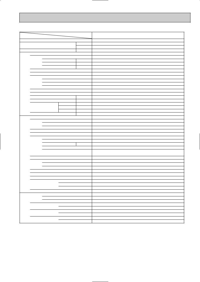
2.Cooling only type
Service Ref.
Item
Function
Capacity |
|
|
Btu/h |
||
|
|
W |
|||
|
|
|
|
||
Total input |
|
|
kW |
||
|
Service Ref. |
|
|
||
|
Power supply (phase, cycle,voltage) |
|
|||
|
|
Input |
|
kW |
|
|
|
Running current |
A |
||
|
|
Starting current |
A |
||
|
External finish (Panel) |
|
|
||
|
Heat exchanger |
|
|
||
unit |
|
Fan (drive) o No. |
|
||
Fan |
Fan motor output |
kW |
|||
Indoor |
Airflow (Lo-Mi2-Mi1-Hi) |
K/ min (CFM) |
|||
|
|||||
|
|
||||
|
|
External static pressure |
Pa (mmAq) |
||
|
Booster heater |
|
kW |
||
|
Operation control & Thermostat |
|
|||
|
Sound level (Lo-Mi2-Mi1-Hi) |
dB |
|||
|
Unit drain pipe I.D. |
|
mm (in.) |
||
|
|
|
W |
mm (in.) |
|
|
Dimensions |
D |
mm (in.) |
||
|
|
|
H |
mm (in.) |
|
|
Weight |
|
|
kg (lbs.) |
|
|
Service Ref. |
|
|
||
|
Power supply (phase, cycle, voltage) |
|
|||
|
|
Running current |
A |
||
|
|
Starting current |
A |
||
|
External finish |
|
|
||
|
Refrigerant control |
|
|
||
|
Compressor |
|
|
||
|
|
Model |
|
|
|
unit |
|
Motor output |
|
kW |
|
|
Starter type |
|
|
||
|
|
|
|
||
Outdoor |
|
Protection devices |
|
||
Heat exchanger |
|
|
|||
|
|
|
|||
|
|
Fan (drive) o No. |
|
||
|
Fan |
Fan motor output |
kW |
||
|
|
Airflow |
|
K/ min (CFM) |
|
|
Crankcase heater |
|
W |
||
|
Defrost method |
|
|
||
|
Sound level |
Cooling |
dB |
||
|
|
|
W |
mm (in.) |
|
|
Dimensions |
D |
mm (in.) |
||
|
|
|
H |
mm (in.) |
|
|
Weight |
|
|
kg (lbs.) |
|
|
Refrigerant |
|
|
||
piping |
|
Charge |
|
kg (lbs.) |
|
|
Oil (Model) |
|
L |
||
|
|
|
|||
Refrigerant |
Pipe size O.D. |
Liquid |
mm (in.) |
||
Gas |
mm (in.) |
||||
|
|||||
|
|
|
|||
|
Connection method |
Indoor side |
|
||
|
Outdoor side |
|
|||
|
|
|
|
||
|
Between the indoor & |
Height difference |
|||
|
outdoor units |
Piping length |
|
||
PLA-P3AA.UK |
PLA-P4AA.UK |
|
|
Cooling |
|
26,600 |
33,100 |
7,800 |
9,700 |
3.51 |
3.62 |
PLA-P3AA.UK |
PLA-P4AA.UK |
Single phase, 50Hz, 220-230-240V |
|
0.17 |
0.26 |
0.81 |
1.25 |
1.0 |
2.0 |
Munsell 0.70Y 8.59/0.97 |
|
Plate fin coil |
|
Turbo fan (direct) o 1 |
|
0.070 |
0.120 |
15-16-18-20 (530-565-635-705) |
20-23-26-28 (705-810-920-990) |
0 (direct blow) |
|
— |
|
Remote controller & built-in |
|
28-30-32-34 |
33-36-39-41 |
32 (1-1/4) |
|
UNIT : 840 (33-1/16), PANEL : 950 (37-3/8) |
UNIT : 840 (33-1/16), PANEL: 950 (37-3/8) |
UNIT : 840 (33-1/16), PANEL : 950 (37-3/8) |
UNIT : 840 (33-1/16), PANEL: 950 (37-3/8) |
UNIT : 258 (10-1/2), PANEL : 30 (1-3/16) |
UNIT : 298 (11-3/4), PANEL : 30 (1-3/16) |
UNIT : 26 (57), PANEL : 5 (11) |
UNIT : 29 (64), PANEL : 5 (11) |
PU-P3VGA / PU-P3YGA |
PU-P4YGA |
w1 |
3 phase, 50Hz, 380-400-415V (4wires) |
14.64 / 5.46 |
5.49 |
93 / 41 |
45 |
Munsell 5Y 8/1 |
|
Linear expansion valve |
|
Hermetic |
|
NE52VNJM / NE52YDJM |
NE56YDJM |
2.5 |
2.7 |
Line start |
|
Internal thermostat, HP switch, Discharge thermo. / |
Anti-phase protector, Thermal relay, |
Thermal rely, Discharge thermo, HP switch, Anti-phase protector. |
Discharge thermo, HP switch |
Plate fin coil |
|
Propeller (direct) o 1 |
Propeller (direct) o 2 |
0.070 |
0.070+0.070 |
50 (1,770) |
85 (3,000) |
38 |
|
— |
|
49 |
51 |
900 (35-7/16) |
|
330+20 (13+3/4) |
|
855 (33-5/8) |
1,260 (49-5/8) |
82 (181) |
96 (212) |
R407C |
|
3.7 (8.2) |
4.0 (8.8) |
1.6 (MEL56) |
|
9.52 (3/8) |
|
15.88 (5/8) |
19.05 (3/4) |
Flared
Flared
Max. 50m
Max. 50m
NOTE: 1. |
Rating conditions (ISO T1) |
|
|
|
|
||||
|
Cooling : |
Indoor: D.B. 27: (80˚F) W.B. 19: (66˚F) |
Outdoor : D.B. 35: (95˚F) W.B. 24: (75˚F) |
||||||
|
Refrigerant piping length (one way) : 5m (16ft.) |
|
|
||||||
2. |
Guaranteed operating range |
|
|
|
|
||||
|
|
|
|
|
|
|
|
||
|
|
|
|
|
Indoor |
|
Outdoor |
|
|
|
Cooling |
|
Upper limit |
D.B. 35˚C, |
W.B. 22.5˚C |
|
D.B. 46˚C |
|
|
|
|
Lower limit |
D.B. 19˚C, |
W.B. 15˚C |
|
D.B. -5˚C |
|
||
3. |
Above data based on indicated voltage |
|
|
||||||
|
Indoor unit |
|
Single phase 240V 50Hz |
|
|
||||
|
Outdoor unit |
Single phase 240V 50Hz, 3 phase 415V 50Hz |
|||||||
w1.Single phase, 50Hz, 220-230-240V / 3 phase, 50Hz, 380-400-415V (4wires)
19
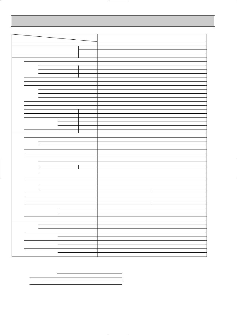
Item |
|
|
|
Service Ref. |
|
|
|
|
|
||
Function |
|
|
|
|
|
Capacity |
|
|
Btu/h |
||
|
|
W |
|||
|
|
|
|
|
|
Total input |
|
|
kW |
||
|
|
Service Ref. |
|
|
|
|
|
Power supply (phase, cycle,voltage) |
|
||
|
|
|
Input |
|
kW |
|
|
|
Running current |
A |
|
|
|
|
Starting current |
A |
|
|
|
External finish (Panel) |
|
|
|
|
|
Heat exchanger |
|
|
|
|
|
|
Fan (drive) o No. |
|
|
unit |
|
Fan |
Fan motor output |
kW |
|
|
Airflow (Lo-Mi2-Mi1-Hi) |
K/ min (CFM) |
|||
Indoor |
|
|
External static pressure |
Pa (mmAq) |
|
|
|
Booster heater |
|
kW |
|
|
|
Operation control & Thermostat |
|
||
|
|
Sound level (Lo-Mi2-Mi1-Hi) |
dB |
||
|
|
Unit drain pipe I.D. |
|
mm (in.) |
|
|
|
|
|
W |
mm (in.) |
|
|
Dimensions |
D |
mm (in.) |
|
|
|
|
|
H |
mm (in.) |
|
|
Weight |
|
|
kg (lbs.) |
|
|
Service Ref. |
|
|
|
|
|
Power supply (phase, cycle, voltage) |
|
||
|
|
|
Running current |
A |
|
|
|
|
Starting current |
A |
|
|
|
External finish |
|
|
|
|
|
Refrigerant control |
|
|
|
|
|
Compressor |
|
|
|
|
|
|
Model |
|
|
unit |
|
|
Motor output |
|
kW |
|
|
Starter type |
|
|
|
Outdoor |
|
|
|
|
|
|
|
Protection devices |
|
||
|
|
|
|
||
|
|
Heat exchanger |
|
|
|
|
|
|
Fan (drive) o No. |
|
|
|
|
Fan |
Fan motor output |
kW |
|
|
|
|
Airflow |
|
K/ min (CFM) |
|
|
Crankcase heater |
|
W |
|
|
|
Defrost method |
|
|
|
|
|
Sound level |
Cooling |
dB |
|
|
|
|
|
W |
mm (in.) |
|
|
Dimensions |
D |
mm (in.) |
|
|
|
|
|
H |
mm (in.) |
|
|
Weight |
|
|
kg (lbs.) |
|
|
Refrigerant |
|
|
|
piping |
|
|
Charge |
|
kg (lbs.) |
|
|
Oil (Model) |
|
L |
|
|
|
|
|
||
Refrigerant |
|
Pipe size O.D. |
Liquid |
mm (in.) |
|
|
Gas |
mm (in.) |
|||
|
|
||||
|
|
|
|
||
|
|
Connection method |
Indoor side |
|
|
|
|
Outdoor side |
|
||
|
|
|
|
|
|
|
|
Between the indoor & |
Height difference |
||
|
|
outdoor units |
Piping length |
|
|
|
|
|
|
|
|
NOTE: 1. |
Rating conditions (ISO T1) |
|
|
||||
|
Cooling : |
Indoor : D.B. 27: (80˚F) W.B. 19: (66˚F) |
|||||
|
Refrigerant piping length (one way) : 5m (16ft.) |
||||||
2. |
Guaranteed operating range |
|
|
||||
|
|
|
|
|
Indoor |
|
|
|
|
|
|
|
|
||
|
Cooling |
|
Upper limit |
D.B. 35˚C, |
W.B. 22.5˚C |
|
|
|
|
Lower limit |
D.B. 19˚C, |
W.B. 15˚C |
|
||
3. |
Above data based on indicated voltage |
||||||
|
Indoor unit |
|
Single phase 240V 50Hz |
||||
|
Outdoor unit |
3 phase 415V 50Hz |
|||||
PLA-P5AA.UK |
|
PLA-P6AA.UK |
|
|
|
Cooling |
||
43,700 |
|
48,000 |
12,800 |
|
14,300 |
5.55 |
|
6.70 |
PLA-P5AA.UK |
|
PLA-P6AA.UK |
Single phase, 50Hz, 220-230-240V |
||
0.30 |
|
0.34 |
1.43 |
|
1.64 |
2.0 |
|
2.0 |
Munsell 0.70Y 8.59/0.97 |
||
Plate fin coil |
||
Turbo fan (direct) o 1 |
||
0.120 |
||
22-25-28-30 (775-880-990-1,060) |
|
22-25-28-30 (775-880-990-1,060) |
0 (direct blow) |
||
— |
|
|
Remote controller & built-in |
||
35-38-41-43 |
|
37-40-43-45 |
32 (1-1/4) |
||
UNIT : 840 (33-1/16), PANEL : 950 (37-3/8) |
||
UNIT : 840 (33-1/16), PANEL : 950 (37-3/8) |
||
UNIT : 298 (11-3/4), |
PANEL : 30 (1-3/16) |
|
UNIT : 30 (66), |
PANEL : 5 (11) |
|
PU-P5YGA |
|
PU-P6YGA |
3 phase, 50Hz, 380-400-415V (4wires) |
||
8.39 |
|
10.17 |
79 |
|
84 |
Munsell 5Y 8/1 |
||
Linear expansion valve |
||
Hermetic |
||
HE86YAA |
|
HE101YAA |
4.3 |
|
5.1 |
Line start
Internal thermostat, Anti-phase protector, Thermal relay, HP switch, LP switch, Discharge thermo.
|
Plate fin coil |
|
Propeller (direct) o 2 |
|
0.075+0.075 |
95 (3,360) |
100 (3,530) |
|
38 |
|
— |
53 |
57 |
1,050 (41-5/16)
330+20 (13+3/4)
1,260 (49-5/8)
122 (269)
R407C
5.8 (12.8)
2.0 (MEL32)
9.52 (3/8)
19.05 (3/4)
Flared
Flared
Max. 50m
Max. 50m
Outdoor: D.B. 35: (95˚F) W.B. 24: (75˚F)
Outdoor
D.B. 46˚C
D.B. -5˚C
20
|
|
|
|
Service Ref. |
|
Item |
|
|
|
|
|
Function |
|
|
|
|
|
Capacity |
|
|
|
Btu/h |
|
|
|
|
W |
||
|
|
|
|
||
Total input |
|
|
kW |
||
|
Service Ref. |
|
|
||
|
Power supply (phase, cycle,voltage) |
|
|||
|
|
Input |
|
kW |
|
|
|
Running current |
A |
||
|
|
Starting current |
A |
||
|
External finish (Panel) |
|
|
||
|
Heat exchanger |
|
|
||
unit |
|
Fan (drive) o No. |
|
||
Fan |
Fan motor output |
kW |
|||
Indoor |
Airflow (Lo-Mi2-Mi1-Hi) |
K/ min (CFM) |
|||
|
|||||
|
|
||||
|
|
External static pressure |
Pa (mmAq) |
||
|
Booster heater |
|
kW |
||
|
Operation control & Thermostat |
|
|||
|
Sound level (Lo-Mi2-Mi1-Hi) |
dB |
|||
|
Unit drain pipe I.D. |
|
mm (in.) |
||
|
|
|
W |
mm (in.) |
|
|
Dimensions |
D |
mm (in.) |
||
|
|
|
H |
mm (in.) |
|
|
Weight |
|
|
kg (lbs.) |
|
|
Service Ref. |
|
|
||
|
Power supply (phase, cycle, voltage) |
|
|||
|
|
Running current |
A |
||
|
|
Starting current |
A |
||
|
External finish |
|
|
||
|
Refrigerant control |
|
|
||
|
Compressor |
|
|
||
|
|
Model |
|
|
|
unit |
|
Motor output |
|
kW |
|
|
Starter type |
|
|
||
|
|
|
|
||
Outdoor |
|
Protection devices |
|
||
Heat exchanger |
|
|
|||
|
|
|
|||
|
|
Fan (drive) o No. |
|
||
|
Fan |
Fan motor output |
kW |
||
|
|
Airflow |
|
K/ min (CFM) |
|
|
Crankcase heater |
|
W |
||
|
Defrost method |
|
|
||
|
Sound level |
Cooling |
dB |
||
|
|
|
W |
mm (in.) |
|
|
Dimensions |
D |
mm (in.) |
||
|
|
|
H |
mm (in.) |
|
|
Weight |
|
|
kg (lbs.) |
|
|
Refrigerant |
|
|
||
piping |
|
Charge |
|
kg (lbs.) |
|
|
Oil (Model) |
|
L |
||
|
|
|
|||
Refrigerant |
Pipe size O.D. |
Liquid |
mm (in.) |
||
Gas |
mm (in.) |
||||
|
|||||
|
|
|
|||
|
Connection method |
Indoor side |
|
||
|
Outdoor side |
|
|||
|
|
|
|
||
|
Between the indoor & |
Height difference |
|||
|
outdoor units |
Piping length |
|
||
|
|
|
|
|
|
NOTE: 1. |
Rating conditions (ISO T1) |
|
|
||
|
Cooling : |
Indoor: D.B. 27: (80˚F) W.B. 19: (66˚F) |
|||
|
Refrigerant piping length (one way) : 5m (16ft.) |
||||
2. |
Guaranteed operating range |
|
|
||
|
|
|
Indoor |
|
|
|
|
|
|
||
|
Cooling |
Upper limit |
D.B. 35˚C, |
W.B. 22.5˚C |
|
|
Lower limit |
D.B. 19˚C, |
W.B. 15˚C |
|
|
PLA-P3AA.UK |
|
PLA-P4AA.UK |
PLA-P3AA1.UK |
|
PLA-P4AA1.UK |
Cooling |
||
26,600 |
|
33,100 |
7,800 |
|
9,700 |
3.44 |
|
3.69 |
PLA-P3AA.UK |
|
PLA-P4AA.UK |
PLA-P3AA1.UK |
|
PLA-P4AA1.UK |
Single phase, 50Hz, 220-230-240V |
||
0.17 |
|
0.26 |
0.81 |
|
1.25 |
1.0 |
|
2.0 |
Munsell 0.70Y 8.59/0.97 |
||
Plate fin coil |
||
Turbo fan (direct) o 1 |
||
0.070 |
|
0.120 |
15-16-18-20 (530-565-635-705) |
|
20-23-26-28 (705-810-920-990) |
0 (direct blow) |
||
— |
|
|
Remote controller & built-in |
||
28-30-32-34 |
|
33-36-39-41 |
32 (1-1/4) |
||
UNIT : 840 (33-1/16), PANEL : 950 (37-3/8) |
|
UNIT : 840 (33-1/16), PANEL: 950 (37-3/8) |
UNIT : 840 (33-1/16), PANEL : 950 (37-3/8) |
|
UNIT : 840 (33-1/16), PANEL: 950 (37-3/8) |
UNIT : 258 (10-1/2), PANEL : 30 (1-3/16) |
|
UNIT : 298 (11-3/4), PANEL : 30 (1-3/16) |
UNIT : 24 (53), PANEL : 5 (11) |
|
UNIT : 30 (66), PANEL : 5 (11) |
PU-P3VGAA.UK / PU-P3YGAA.UK |
|
PU-P4VGAA.UK / PU-P4YGAA.UK |
Single phase, 50Hz, 220-230-240V/ 3 phase, 50Hz, 380-400-415V (4wires) |
||
14.81 / 5.29 |
|
15.71 / 5.55 |
93 / 47 |
|
99 / 49 |
Munsell 5Y 7/1 |
||
Linear expansion valve |
||
Hermetic |
||
NE52VNJMT / NE52YDKMT |
|
NE56VNJMT / NE56YDKMT |
2.5 |
|
2.7 |
Line start |
||
Internal thermostat, HP switch, Discharge thermo. / |
||
Thermal relay, HP switch, Discharge thermo. |
||
Plate fin coil |
||
Propeller (direct) o 1 |
|
Propeller (direct) o 2 |
0.070 |
|
0.070+0.070 |
50 (1,770) |
|
85 (3,000) |
38 |
|
|
— |
|
|
49 |
|
51 |
900 (35-7/16) |
||
330+20 (13+3/4) |
||
855 (33-5/8) |
|
1,260 (49-5/8) |
82 (181) |
|
96 (212) |
R407C |
||
3.3 (7.3) |
|
4.0 (8.8) |
1.3 (Ester)MEL56 |
||
9.52 (3/8) |
||
15.88 (5/8) |
|
19.05 (3/4) |
Flared
Flared
Max. 50m
Max. 50m
Outdoor : D.B. 35: (95˚F) W.B. 24: (75˚F)
Outdoor
D.B. 46˚C
D.B. -5˚C
3. Above data based on indicated voltage
Indoor unit |
Single phase 240V |
50Hz |
Outdoor unit |
Single phase 240V |
50Hz, 3 phase 415V 50Hz |
21
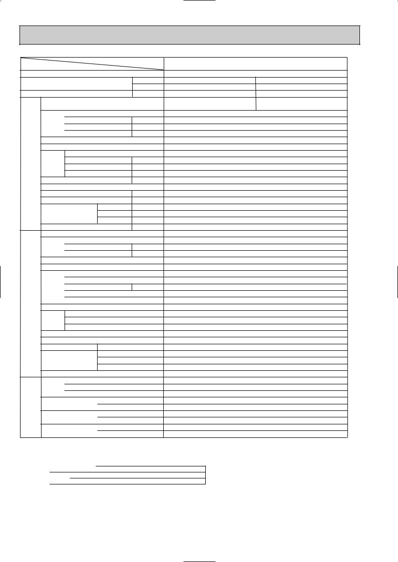
Item |
|
|
|
Service Ref. |
|
|
|
|
|
||
Function |
|
|
|
||
Capacity |
|
|
Btu/h |
||
|
|
W |
|||
|
|
|
|
||
Total input |
|
|
kW |
||
|
Service Ref. |
|
|
||
|
Power supply (phase, cycle,voltage) |
|
|||
|
|
Input |
|
kW |
|
|
|
Running current |
A |
||
|
|
Starting current |
A |
||
|
External finish (Panel) |
|
|
||
|
Heat exchanger |
|
|
||
|
|
Fan (drive) o No. |
|
||
unit |
Fan |
Fan motor output |
kW |
||
Airflow (Lo-Mi2-Mi1-Hi) |
K/ min (CFM) |
||||
Indoor |
|
External static pressure |
Pa (mmAq) |
||
|
|
||||
|
Booster heater |
|
kW |
||
|
Operation control & Thermostat |
|
|||
|
Sound level (Lo-Mi2-Mi1-Hi) |
dB |
|||
|
Unit drain pipe I.D. |
|
mm (in.) |
||
|
|
|
W |
mm (in.) |
|
|
Dimensions |
D |
mm (in.) |
||
|
|
|
H |
mm (in.) |
|
|
Weight |
|
|
kg (lbs.) |
|
|
Service Ref. |
|
|
||
|
Power supply (phase, cycle, voltage) |
|
|||
|
|
Running current |
A |
||
|
|
Starting current |
A |
||
|
External finish |
|
|
||
|
Refrigerant control |
|
|
||
|
Compressor |
|
|
||
|
|
Model |
|
|
|
unit |
|
Motor output |
|
kW |
|
|
Starter type |
|
|
||
Outdoor |
|
|
|
||
|
Protection devices |
|
|||
|
|
|
|||
|
Heat exchanger |
|
|
||
|
|
Fan (drive) o No. |
|
||
|
Fan |
Fan motor output |
kW |
||
|
|
Airflow |
|
K/ min (CFM) |
|
|
Crankcase heater |
|
W |
||
|
Defrost method |
|
|
||
|
Sound level |
Cooling |
dB |
||
|
|
|
W |
mm (in.) |
|
|
Dimensions |
D |
mm (in.) |
||
|
|
|
H |
mm (in.) |
|
|
Weight |
|
|
kg (lbs.) |
|
|
Refrigerant |
|
|
||
piping |
|
Charge |
|
kg (lbs.) |
|
|
Oil (Model) |
|
L |
||
|
|
|
|||
Refrigerant |
Pipe size O.D. |
Liquid |
mm (in.) |
||
Gas |
mm (in.) |
||||
|
|||||
|
|
|
|||
|
Connection method |
Indoor side |
|
||
|
Outdoor side |
|
|||
|
|
|
|
||
|
Between the indoor & |
Height difference |
|||
|
outdoor units |
Piping length |
|
||
NOTE: 1. |
Rating conditions (ISO T1) |
|
|
||||
|
Cooling : |
Indoor : D.B. 27: (80˚F) W.B. 19: (66˚F) |
|||||
|
Refrigerant piping length (one way) : 5m (16ft.) |
||||||
2. |
Guaranteed operating range |
|
|
||||
|
|
|
|
|
Indoor |
|
|
|
|
|
|
|
|
||
|
Cooling |
|
Upper limit |
D.B. 35˚C, |
W.B. 22.5˚C |
|
|
|
|
Lower limit |
D.B. 19˚C, |
W.B. 15˚C |
|
||
3. |
Above data based on indicated voltage |
||||||
|
Indoor unit |
|
Single phase 240V 50Hz |
||||
|
Outdoor unit |
3 phase 415V 50Hz |
|||||
PLA-P5AA.UK |
|
PLA-P6AA.UK |
|
|
|
Cooling |
||
43,700 |
|
48,000 |
12,800 |
|
14,300 |
5.00 |
|
5.94 |
PLA-P5AA.UK |
PLA-P6AA.UK |
|
PLA-P5AA1.UK |
PLA-P6AA1.UK |
|
Single phase, 50Hz, 220-230-240V |
||
0.30 |
|
0.34 |
1.43 |
|
1.64 |
2.0 |
|
2.0 |
Munsell 0.70Y 8.59/0.97 |
||
Plate fin coil |
||
Turbo fan (direct) o 1 |
||
0.120 |
|
|
22-25-28-30 (775-880-990-1,060) |
||
0 (direct blow) |
||
— |
|
|
Remote controller & built-in |
||
35-38-41-43 |
|
37-40-43-45 |
32 (1-1/4) |
||
UNIT : 840 (33-1/16), PANEL : 950 (37-3/8) |
||
UNIT : 840 (33-1/16), PANEL : 950 (37-3/8) |
||
UNIT : 298 (11-3/4), |
PANEL : 30 (1-3/16) |
|
UNIT : 30 (66), PANEL : 5 (11) |
|
UNIT : 32 (71), PANEL : 5 (11) |
PU-P5YGAA.UK |
|
PU-P6YGAA.UK |
3 phase, 50Hz, 380-400-415V (4wires) |
||
7.60 |
|
9.03 |
65.5 |
|
74 |
Munsell 5Y 7/1 |
||
Linear expansion valve |
||
Hermetic |
||
ZR61KCE-TFD |
|
ZR72KCE-TFD |
3.5 |
|
4.2 |
Line start |
||
Internal thermostat,Thermal relay, HP switch, Discharge thermo. |
||
Plate fin coil |
||
Propeller (direct) o 2 |
||
0.070+0.070 |
||
95 (3,360) |
|
100 (3,530) |
38 |
|
|
— |
|
|
55 |
|
57 |
1,050 (41-5/16) |
||
330+20 (13+3/4) |
||
1,260 (49-5/8) |
||
122 (269) |
||
R407C |
||
4.6 (10.1) |
|
4.9 (10.8) |
1.690 (Ester)MMM-POE |
|
1.774 (Ester)MMM-POE |
9.52 (3/8)
19.05 (3/4)
Flared
Flared
Max. 50m
Max. 50m
Outdoor: D.B. 35: (95˚F) W.B. 24: (75˚F)
Outdoor
D.B. 46˚C
D.B. -5˚C
22
 Loading...