


PK-1.6FLA3
Mitsubishi PK-1.6FLA3, PK-2FLA3, PK-2.5FLA2, PK-2.5FLA3, PK-2.5FLA4 Service Manual
...
TECHNICAL & SERVICE MANUAL
SPLIT-TYPE,AIR CONDITIONERS
CONTENTS
1. TECHNICAL CHANGES·······························3
2. COMBINATION OF INDOOR
AND OUTDOOR UNITS··············3
3. PART NAMES AND FUNCTIONS················3
4. SPECIFICATIONS·········································6
5. DATA ···························································13
6. OUTLINES AND DIMENSIONS ··················16
7. WIRING DIAGRAM·····································20
8.
REFRIGERANT SYSTEM DIAGRAM
···············22
9. OPERATION FLOW-CHART······················24
10. MICROPROCESSOR CONTROL···············27
11. TROUBLESHOOTING·································36
12. DISASSEMBLY PROCEDURE ···················39
13. PARTS LIST················································42
14. OPTIONAL PARTS ·····································54
No. OC129
REVISED EDITION-A
Indoor unit
Wall Mounted
Series PK
TEMP
ON / OFF
NOT AVAILABLE
AM
PM
AM
PM
˚C
REMOTE CONTROLLER
Indoor unit
[ Model names ] [ Service Ref. ]
1997, 1999, 2001 1997 1999 2001
PK-1.6FLA
PK-1.6FLA
3
PK-2FLA
PK-2FLA
3
PK-2.5FLA
PK-2.5FLA
2
PK-2.5FLA
3
PK-2.5FLA
4
PK-3FLA
PK-3FLA
2
PK-3FLA
3
PK-3FLA
4
PK-3FLA
5
PK-4FLSA
PK-4FLSA
2
PK-4FLSA
3
PK-4FLSA
4
1997
PK-2.5FLA
4
PK-3FLA
5
PK-4FLSA
4
PK-1.6FLA
3
PK-2FLA
3
PK-2.5FLA
2/3
PK-3FLA
2/3/4
PK-4FLSA
2/3
• PK-2.5FLA
3
, PK-2.5FLA
4
, PK-3FLA
3
, PK-3FLA
4
, PK-3FLA
5
,
PK-4FLA
3
and PK-4FLA
4
are added in REVISED EDITION-A.
• Please void OC129 and OC200.
• This manual does not cover outdoor units. When servicing
them, please refer to the service manual No.OC127 REVISED
EDITION-A, OC187, OC217 REVISED EDITION-A and this
manual in a set.


3
TECHNICAL CHANGES
1
3
PART NAMES AND FUNCTIONS
● Indoor Unit
Air intake
Room air is suctioned
in here.
(Removes dust and dirt from the intake air.)
Disperses airflow up and
down as well as adjusts the
angle of air flow direction.
Filter Air intake grille
Air outletAir outlet
Swing louvers
Air flow can be changed to horizontally
by moving the Guide vane to the left or
right.
Guide vane
PK-3FLA2 ➔ PK-3FLA3
● Outdoor units has changed.
PK-2.5FLA2 ➔ PK-2.5FLA3
PK-3FLA3 ➔ PK-3FLA4
PK-4FLSA2 ➔ PK-4FLSA3
● NOSE has changed by changing its shape.
● UNDER PLATE has changed.
● BOX ASSEMBLY has changed by changing its shape.
● DRAIN PAN has changed by changing its shape.
PK-2.5FLA3 ➔ PK-2.5FLA4
PK-3FLA4 ➔ PK-3FLA5
PK-4FLSA3 ➔ PK-4FLSA4
● The parts No. of REMOTE CONTROLLER has changed.
(The following parts numbers are interchangeable.)
2
COMBINATION OF INDOOR AND OUTDOOR UNITS
Outdoor unit
(OC187)
Outdoor unit
(OC127 REVISED EDITION-A)
PU-1.6
VLJSA
2
VJA2 NJA1 VJA2 NJA1 VJA2 YJA2 YJA3 NJA1
VLJSA
2
YJSA
2
YJSA
3
TJSA
2
VJC YJC
PU-2 PU-2.5 PU-3 PU-4 PU-3
(OC217
REVISED EDITION-A)
Outdoor unit
VJB YJB
PU-3
PK-1.6FLA
3
PK-2FLA
3
PK-3FLA
2
PK-2.5FLA
2
PK-2.5FLA
3
PK-2.5FLA
4
PK-4FLSA
2
PK-4FLSA
3
PK-4FLSA
4
PK-3FLA
3
PK-3FLA
4
PK-3FLA
5
—
—
—
—
—
—
—
—
—
—
—
—
—
—
—
—
—
—
—
—
—
—
—
—
—
—
—
—
—
—
—
—
—
—
—
—
—
—
—
—
—
—
—
—
—
—
—
—
—
—
—
—
—
—
—
—
—
—
—
—
—
—
—
—
—
—
—
—
—
—
—
—
—
—
—
—
—
—
—
—
—
—
Indoor unit
TEMP
ON / OFF
NOT AVAILABLE
AM
PM
AM
PM
˚C
[ T7W 570 200 ] [ T7W E06 714 ]
4
TEMP
ON / OFF
NOT AVAILABLE
AM
PM
AM
PM
˚C
MODE
FAN
VANE STOP
START
CLOCK
HR MIN.
ON / OFF
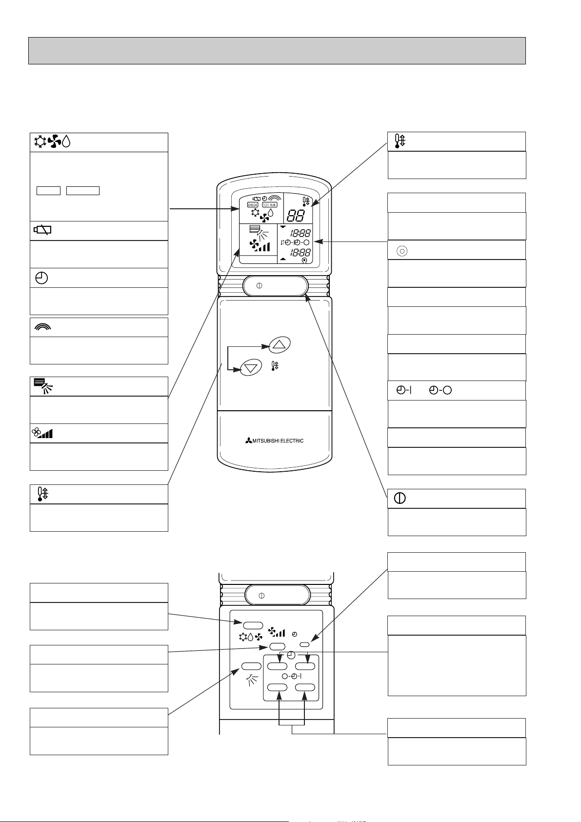
display
OPERATION MODE display
Operation mode display indicates which opera-
tion mode is in effect.
• • display
CHECK&TEST RUN display indicates that the
unit is being checked or test-run.
TEST RUNCHECK
●Remote controller
● When cover is closed.
display
Displays when batteries are dead.
display
Displays when setting timer.
display
Lights when signal is sent from the remote
controller to the indoor unit.
display
The vertical direction of airflow is indicated in
marks.
display
FAN SPEED display indicates which fan speed
has been selected.
▼
MODE SELECT button
MODE SELECT button is used to change
cooling. dry (dehumidify) and fan (ventilation)
operation modes.
FAN SPEED SELECT button
FAN SPEED SELECT button selects low or
high fan speed.
VANE CONTROL button
VANE CONTROLbutton regulates the vertical
distribution of airflow.
display
SET TEMP. display indicates desired tempera-
ture set.
CLOCK display
DIsplays the current time.
“ ”display
Flashes when the current time is displayed.
TIMER display
Displays when in timer operation or when set-
ting timer.
“ ” “ ” display
Displays the order of timer operation.
“ ” “ ” display
Displays whether timer is on or off.
button
Push to start operation. Push again to stop
operation.
HR. and MIN.buttons
Buttons used to set the “hour and minute” of
the current time and timer time.
➡
➡
“ ” “ ” display
Displays when the current time and the timer
time can be changed.
▼
▼
SET CLOCK button
Button used to set the current time.
● When cover is open.
button
SET TEMPERATURE button sets any desired
room temperature.
TIMER CONTROL buttons
STOP (OFF timer): when this switch is set,
the air conditioner will be automatically
stopped at the preset time.
START(ON timer): when this switch is set, the
air conditioner will be automatically started at
the preset time.
PK-1.6FLA3
PK-2FLA3
PK-2.5FLA2, PK-2.5FLA3
PK-3FLA2, PK-3FLA3, PK-3FLA4
PK-4FLSA2, PK-4FLSA3
Part No.
[ T7W 570 200 ]
5
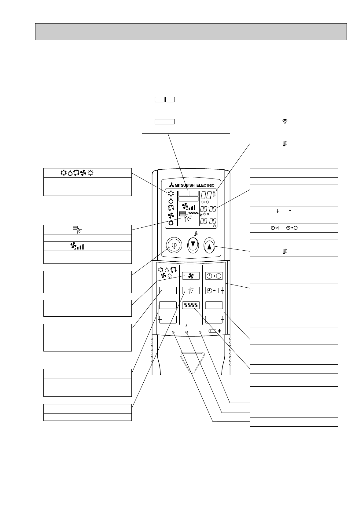
●Wireless remote controller
● When cover is open.
ON/OFF TEMP
FAN
VANE
TEST RUN
AUTO STOP
AUTO START
h
min
LOUVER
MODE
CHECK
RESETSET CLOCK
MODEL SELECT
NOT AVAILABLE
CHECK
TEST RUN
˚C
AMPM
AMPM
VANE CONTROL button
Used to change the air flow direction.
CLOCK button
RESET button
SET button
ON/OFF button
The unit is turned ON and OFF alternately
each time the button is pressed.
LOUVER button
This switch the horizontal fan motion ON
and OFF.
(Not available for this model.)
MODE SELECT button
Used to switch the operation mode between
cooling, drying, fan.
CHECK-TEST RUN button
Only press this button to perform an inspec-
tion check or test operation.
Do not use it for normal operation.
FAN SPEED SELECT button
Used to change the fan speed.
TIMER display
Displays when in timer operation or when
setting timer.
button
SET TEMPERATURE button sets any desired
room temperature.
CLOCK display
Displays the current time.
“ ” “ ” display
Displays the order of timer operation.
“ ” “ ” display
Displays whether timer is on or off.
Buttons used to set the “hour and minute” of
the current time and timer settings.
h and min buttons
display
SET TEMP. display indicates desired temper-
ature set.
display
FAN SPEED display indicates which fan
speed has been selected.
display
The vertical direction of air flow is indicated.
display
Blinks when model is selected.
display
Lights up while transmission to the indoor
unit is mode using switches.
display
CHECK&TEST RUN display indicates that
the unit is being checked or test-run.
display
OPERATION MODE display
Operation mode display indicates which op-
eration mode is in effect.
TIMER CONTROL buttons
AUTO STOP (OFF timer): when this switch
is set, the air conditioner will be au-
tomatically stopped at the preset time.
AUTO START (ON timer): when this switch
is set, the air conditioner will be automatical-
ly started at the preset time.
MODEL SELECT
CHECK
TEST RUN
PK-2.5FLA4
PK-3FLA5
PK-4FLSA4
Part No.
[ T7W E06 714 ]
6
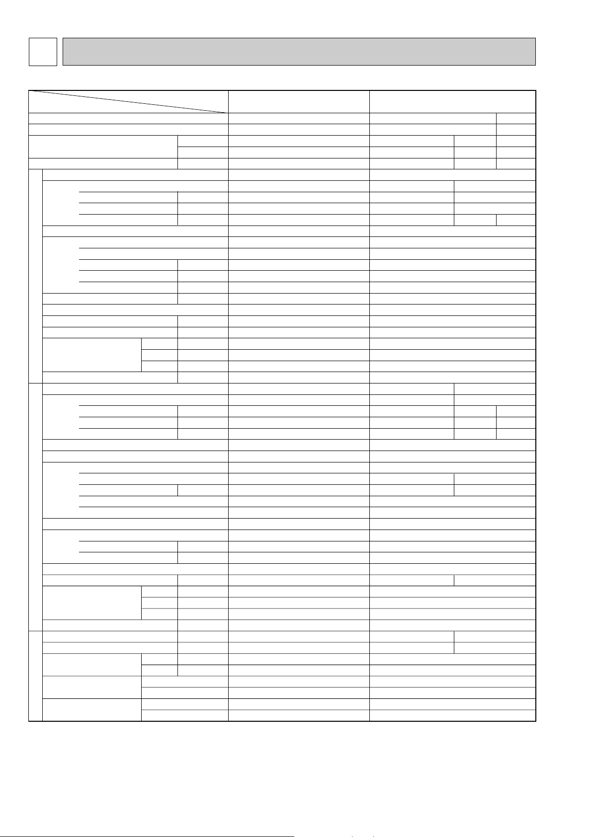
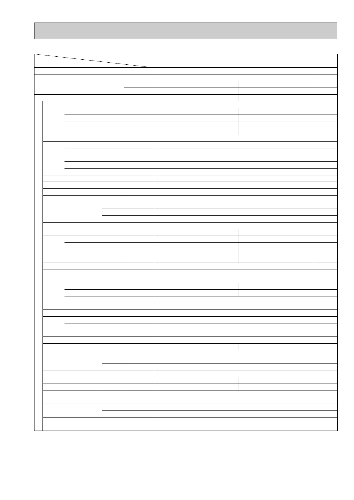
4 SPECIFICATIONS
Item
Service Ref.
PK-1.6FLA
3 PK-2FLA3
PK-2FLA3
PU-2VJA2
Single, 50Hz, 220/240V
2.44 / 2.48
11.3 / 10.8(98/96)
48 / 52
PU-2NJA
1
Single, 60Hz, 220V
2.45
11.4(98)
54
2.97
13.6(99)
54
Munsell 5Y 7/1
Capillary tube
Hermetic
Line start
Inner thermostat, HP/LP switch
Plate fin coil
Propeller (direct) o 1
0.065
45 (1588)
—
870 (34-1/4)
295 (11-5/8)
650 (25-5/8)
60 (132)
9.52 (3/8)
15.88 (5/8)
Flared
Flared
w3 Max. 20m
w3 Max. 30m
49 50
32 / 38
R-22 1.78 (3.9)
—
R-22 1.9 (4.2)
NHJ41VMD
2.0
NHJ33NBD
1.5
Single, 50Hz, 220/240V
0.08
0.37(98/90)
0.4
Munsell 3.4Y 7.7/0.8(White)
Plate fin coil
Line flow (direct) o 1
0.030
10-14 (353-459)
0 (direct blow)
—
Wireless remote controller & Built-in
38 - 45
20 (13/16)
1,250 (49-3/16)
200 (7-7/8)
300 (11-13/16)
17 (37)
Single, 60Hz, 220V
0.09
0.42(97)
0.5 0.5
w6
w7
16,000
4,600
3.06
19,000
5,450
2.54
27/19.0°C, 35/24°C
Cooling (JIS B8616)
19,100
5,600
2.52/2.56
27/19.0°C, 35/24°C
Cooling (JIS B8616)
13,300
3,900
1.49/1.59
PK-1.6FLA
3
Single, 50Hz, 220/240V
0.07
0.32(99/91)
0.4
Munsell 3.4Y 7.7/0.8(White)
Plate fin coil
Line flow (direct) o 1
0.030
10-13 (353-459)
0 (direct blow)
—
Wireless remote controller & Built-in
36 - 43
20 (13/16)
1,250 (49-3/16)
200 (7-7/8)
300 (11-13/16)
17 (37)
PU-1.6VLJA
2
Single, 50Hz, 220/240V
1.42 / 1.52
6.7 / 6.9 (97/92)
30 /33
Munsell 5Y 7/1
Capillary tube
Hermetic
RH247VFC
1.2
Line start
w4
Plate fin coil
Propeller (direct ) o 1
0.065
45 (1588)
—
49
870 (34-1/4)
295 (11-5/8)
650 (25-5/8)
45 (99)
—
R-22 1.3 (2.9)
9.52 (3/8)
15.88 (5/8)
Flared
Flared
w3 Max. 15m
w3 Max. 20m
Condition
Capacity w1
Total input w1
Service Ref.
Power supply(phase, cycle,voltage)
Input
Running current (Power factor)
Starting current
External finish
Heat exchanger
Fan(drive) o No.
Fan motor output
Airflow (Low-High)
External static pressure
Booster heater
Operation control & Thermostat
Noise level (Low-High) w2
Cond. drain conn. O.D.
Dimensions
Weight
Service Ref.
Power supply (phase, cycle, voltage)
Input
Running current (Power factor)
Starting current
External finish
Refrigerant control
Compressor
Model
Motor output
Starter type
Protection devices
Heat exchanger
Fan(drive) o No.
Fan motor output
Airflow
Defrost method
Noise level w2
Dimensions
Weight
Crankcase heater
Refrigerant Charge
Pipe size O.D.
Connection method
Between the indoor &
outdoor units
Btu/h
W
kW
kW
A (%)
A
kW
m
3
/min(CFM)
Pa(mmAq)
kW
dB
mm(in.)
mm(in.)
mm(in.)
mm(in.)
kg(lbs)
kW
A(%)
A
kW
kW
m
3
/min(CFM)
dB
mm(in.)
mm(in.)
mm(in.)
kg(lbs)
W
kg(lbs)
mm(in.)
mm(in.)
Indoor, Outdoor D.B./W.B.°C
Liquid
Gas
W
D
H
W
D
H
REFRIGERANT PIPING
OUTDOOR UNIT
Indoor side
Outdoor side
Height difference
Piping length
INDOOR UNIT
1. STANDARD SPECIFICATION
w1 Refrigerant piping length (one way) : 5m (16ft)
w2 Noise level is measured in an unacoustic room based on JIS conditions.
w3 Up to 20m it is unnecessary to charge additional refrigerant.
w4 Inner thermostat, HP/LP switch.
w5 Motor protector, Thermal switch, HP/LP switch.
w6 Indoor, Outdoor D.B./W.B. : 29/19°C, 46/24°C
w7 Cooling SSA385, 386
7
w4
w5
22,700
6,650
3.54
3.44
15.8(99)
58
27/19.0°C, 35/24°C
Cooling (JIS B8616)
PK-2.5FLA
2 PK-2.5FLA3 PK-2.5FLA4
PK-2.5FLA2 PK-2.5FLA3 PK-2.5FLA4
Munsell 3.4Y 7.7/0.8(White)
Plate fin coil
Line flow (direct) o 2
0.04
15 - 20(530-706)
0 (direct blow)
—
Wireless remote controller & Built-in
39 - 45
20 (13/16)
1,400 (55-1/8)
235 (9-1/4)
340 (13-3/8)
24 (53)
23,900
7,000
2.56 / 2.62
PU-2.5VJA
2
Single, 50Hz, 220/240V
2.46 / 2.52
11.4 / 10.7 (98/98)
45 / 49
24,400
7,150
3.01
PU-2.5NJA
1
Single, 60Hz, 220V
2.91
13.4 (99)
58
Munsell 5Y 7/1
Capillary tube
Hermetic
Line start
Inner thermostat, HP/LP switch
Plate fin coil
Propeller (direct) o 1
0.085
50 (1765)
—
870 (34-1/4)
295 (+24) (11-5/8 (add 1))
850 (33-7/16)
71 (157)
9.52 (3/8)
15.88 (5/8)
Flared
Flared
w3 Max. 20m
w3 Max. 30m
NHJ41VMD
2.0
NHJ38NBD
1.7
52 53
32 / 38
R-22 2.4 (5.3)
—
R-22 2.4 (5.3)
Single, 60Hz, 220V
0.095
0.44 (98)
0.7
Single, 50Hz, 220/240V
0.095 / 0.095
0.44 / 0.44 (98/90)
0.7 / 0.8
Item
Service Ref.
Condition
Capacity w1
Total input w1
Service Ref.
Power supply(phase, cycle,voltage)
Input
Running current (Power factor)
Starting current
External finish
Heat exchanger
Fan(drive) o No.
Fan motor output
Airflow (Low-High)
External static pressure
Booster heater
Operation control & Thermostat
Noise level (Low-High) w2
Cond. drain conn. O.D.
Dimensions
Weight
Service Ref.
Power supply (phase, cycle, voltage)
Input
Running current (Power factor)
Starting current
External finish
Refrigerant control
Compressor
Model
Motor output
Starter type
Protection devices
Heat exchanger
Fan(drive) o No.
Fan motor output
Airflow
Defrost method
Noise level w2
Dimensions
Weight
Crankcase heater
Refrigerant Charge
Pipe size O.D.
Connection method
Between the indoor &
outdoor units
Btu/h
W
kW
kW
A(%)
A
kW
m
3
/min(CFM)
Pa(mmAq)
kW
dB
mm(in.)
mm(in.)
mm(in.)
mm(in.)
kg(lbs)
kW
A(%)
A
kW
kW
m
3
/min(CFM)
dB
mm(in.)
mm(in.)
mm(in.)
kg(lbs)
W
kg(lbs)
mm(in.)
mm(in.)
Indoor, Outdoor D.B./W.B.°C
Liquid
Gas
W
D
H
W
D
H
REFRIGERANT PIPING
OUTDOOR UNIT
Indoor side
Outdoor side
Height difference
Piping length
INDOOR UNIT
w1 Refrigerant piping length (one way) : 5m (16ft)
w2 Noise level is measured in an unacoustic room based on JIS conditions.
w3 Up to 20m it is unnecessary to charge additional refrigerant.
w4 Indoor, Outdoor D.B./W.B. : 29/19°C, 46/24°C.
w5 Cooling SSA385, 386

8
Item
Service Ref.
PK-3FLA
2
PK-3FLA2
27/19.0°C, 35/24°C
Cooling (JIS B8616)
Munsell 3.4Y 7.7/0.8(White)
Plate fin coil
Line flow (direct) o 2
0.04
15 - 20 (530-706)
0 (direct blow)
—
Wireless remote controller & Built-in
39 - 45
20 (13/16)
1,400 (55-1/8)
235 (9-1/4)
340 (13-3/8)
24 (53)
24,600
7,200
3.28 / 3.30 3.28 / 3.30
27,300
8,000
3.54
Single, 50Hz, 220/240V
0.095 / 0.095
0.44 / 0.44 (98/90)
0.7 / 0.8
Single, 60Hz, 220V
0.095
0.44 (98)
0.7
w4
w5
23,500
6,900
4.19
4.09
20.9(89)
80
PU-3VJA
2
Single, 50Hz, 220/240V
3.18 / 3.20
15.1/13.9(96/96)
68 / 68
Three, 50Hz, 380/415V
3.18 / 3.20
5.7/5.3(85/84)
36 / 36
NHJ52VND
2.2 2.2
NHJ52YDA NHJ52YDE
3.44
17.6(89)
80
PU-3NJA
1
Single, 60Hz, 220V
NHJ47NAD
2.2
w6 w7
53 53
w6
32 / 38
R-22 3.08 (6.8)
32 / 38
R-22 2.88 (6.3)
38
R-22 3.5 (7.7)
Munsell 5Y 7/1
Capillary tube
Hermetic
Line start
Plate fin coil
Propeller (direct) o 1
0.085
50 (1765)
—
870 (34-1/4)
295 (+24) (11-5/8 (add 1))
850 (33-7/16)
73 (161)
9.52 (3/8)
15.88 (5/8)
Flared
Flared
w3 Max. 20m
w3 Max. 30m
Condition
Capacity w1
Total input w1
Service Ref.
Power supply(phase, cycle,voltage)
Input
Running current (Power factor)
Starting current
External finish
Heat exchanger
Fan(drive) o No.
Fan motor output
Airflow (Low-High)
External static pressure
Booster heater
Operation control & Thermostat
Noise level (Low-High) w2
Cond. drain conn. O.D.
Dimensions
Weight
Service Ref.
Power supply (phase, cycle, voltage)
Input
Running current (Power factor)
Starting current
External finish
Refrigerant control
Compressor
Model
Motor output
Starter type
Protection devices
Heat exchanger
Fan(drive) o No.
Fan motor output
Airflow
Defrost method
Noise level w2
Dimensions
Weight
Crankcase heater
Refrigerant Charge
Pipe size O.D.
Connection method
Between the indoor &
outdoor units
Btu/h
W
kW
kW
A(%)
A
kW
m
3
/min(CFM)
Pa(mmAq)
kW
dB
mm(in.)
mm(in.)
mm(in.)
mm(in.)
kg(lbs)
kW
A(%)
A
kW
kW
m
3
/min(CFM)
dB
mm(in.)
mm(in.)
mm(in.)
kg(lbs)
W
kg(lbs)
mm(in.)
mm(in.)
Indoor, Outdoor D.B./W.B.°C
Liquid
Gas
W
D
H
W
D
H
REFRIGERANT PIPING
OUTDOOR UNIT
Indoor side
Outdoor side
Height difference
Piping length
INDOOR UNIT
PU-3YJA2 PU-3YJA3
w1 Refrigerant piping length (one way) : 5m (16ft)
w2 Noise level is measured in an unacoustic room based on JIS conditions.
w3 Up to 20m it is unnecessary to charge additional refrigerant.
w4 Indoor, Outdoor D.B./W.B. : 29/19°C, 46/24°C
w5 Cooling SSA385, 386
w6 Inner thermostat, HP switch, LP switch.
w7 Thermal switch, Reversed-phase protector, HP switch, LP switch, Thermal relay.
9
Item
Service Ref.
PK-3FLA
3 PK-3FLA4 PK-3FLA5
PK-3FLA3 PK-3FLA4 PK-3FLA5
27/19°C , 35/24°C
Cooling (JIS B8616)
Munsell 3.4Y 7.7/0.8(White)
Plate fin coil
Line flow (direct) o 2
0.04
15 - 20 (530-706)
0 (direct blow)
—
Wireless remote controller & Built-in
39 - 45
20 (13/16)
1,400 (55-1/8)
235 (9-1/4)
340 (13-3/8)
24 (53)
27,000
7,900
3.28 / 3.30 3.28 / 3.30
27,300
8,000
3.54
Single, 50Hz, 220/240V
0.095 / 0.095
0.44 / 0.44 (98/90)
0.7 / 0.8
Single, 60Hz, 220V
0.095
0.44 (98)
0.7
w4
w5
23,500
6,900
4.19
4.09
20.9(89)
80
PU-3VJC
Single, 50Hz, 220/240V
3.18 / 3.20
15.1/13.9(96/96)
54 / 58
PU-3YJC
Three, 50Hz, 380/415V
3.18 / 3.20
5.7/5.3(85/84)
34 / 37
NH52VND
2.2
NH52YDE
2.4
3.44
17.6(89)
80
PU-3NJA
1
Single, 60Hz, 220V
NHJ47NAD
2.2
w6 w7
52 53
w6
32 / 38 32 / 38 38
R-22 3.5 (7.7)
Munsell 5Y 7/1
Capillary tube
Hermetic
Line start
Plate fin coil
Propeller (direct) o 1
0.085
50 (1765)
—
870 (34-1/4)
295 (+24) (11-5/8 (add 1))
850 (33-7/16)
73 (161)
9.52 (3/8)
15.88 (5/8)
Flared
Flared
w3 Max. 20m
w3 Max. 30m
Condition
Capacity w1
Total input w1
Service Ref.
Power supply(phase, cycle,voltage)
Input
Running current (Power factor)
Starting current
External finish
Heat exchanger
Fan(drive) o No.
Fan motor output
Airflow (Low-High)
External static pressure
Booster heater
Operation control & Thermostat
Noise level (Low-High) w2
Unit drain pipe O.D.
Dimensions
Weight
Service Ref.
Power supply (phase, cycle, voltage)
Input
Running current (Power factor)
Starting current
External finish
Refrigerant control
Compressor
Model
Motor output
Starter type
Protection devices
Heat exchanger
Fan(drive) o No.
Fan motor output
Airflow
Defrost method
Noise level w2
Dimensions
Weight
Crankcase heater
Refrigerant Charge
Pipe size O.D.
Connection method
Between the indoor &
outdoor units
Btu/h
W
kW
kW
A(%)
A
kW
m
3
/min(CFM)
Pa,mmAq
kW
dB
mm(in.)
mm(in.)
mm(in.)
mm(in.)
kg(lbs)
kW
A(%)
A
kW
kW
m
3
/min(CFM)
dB
mm(in.)
mm(in.)
mm(in.)
kg(lbs)
W
kg(lbs)
mm(in.)
mm(in.)
Indoor, Outdoor D.B./W.B.°C
Liquid
Gas
W
D
H
W
D
H
REFRIGERANT PIPING
OUTDOOR UNIT
Indoor side
Outdoor side
Height difference
Piping length
INDOOR UNIT
R-22 2.8(6.2)
w1 Refrigerant piping length (one way) : 5m (16ft)
w2 Noise level is measured in an unacoustic room based on JIS conditions.
w3 Up to 20m it is unnecessary to charge additional refrigerant.
w4 Indoor, Outdoor D.B./W.B. : 29/19°C, 46/24°C
w5 Cooling SSA385, 386
w6 Inner thermostat, HP switch, LP switch.
w7 Thermal switch, Reversed-phase protector, HP switch, LP switch, Thermal relay.

10
Item
Service Ref.
PK-3FLA
2 PK-3FLA3 PK-3FLA4 PK-3FLA5
PK-3FLA2 PK-3FLA3 PK-3FLA4 PK-3FLA5
27/19°C , 35/24°C
Cooling (JIS B8616)
Munsell 3.4Y 7.7/0.8(White)
Plate fin coil
Line flow (direct) o 2
0.04
15 - 20 (530-706)
0 (direct blow)
—
Wireless remote controller & Built-in
39 - 45
20 (13/16)
1,400 (55-1/8)
235 (9-1/4)
340 (13-3/8)
24 (53)
25,600
7,500
2.75
Single, 50Hz, 220V
0.095
0.44 (98)
0.7
PU-3VJB
Single, 50Hz, 220V
2.65
12.4(97)
54
PU-3YJB
Three, 50Hz, 380V
2.65
4.2(97)
34
NH47VNHT
2.2
NH47YDNT
2.2
w6 w7
52
32 32
Munsell 5Y 7/1
Capillary tube
Hermetic
Line start
Plate fin coil
Propeller (direct) o 1
0.085
50 (1765)
—
870 (34-1/4)
295 (+24) (11-5/8 (add 1))
850 (33-7/16)
73 (161)
9.52 (3/8)
15.88 (5/8)
Flared
Flared
w3 Max. 20m
w3 Max. 30m
Condition
Capacity w1
Total input w1
Service Ref.
Power supply(phase, cycle,voltage)
Input
Running current (Power factor)
Starting current
External finish
Heat exchanger
Fan(drive) o No.
Fan motor output
Airflow (Low-High)
External static pressure
Booster heater
Operation control & Thermostat
Noise level (Low-High) w2
Unit drain pipe O.D.
Dimensions
Weight
Service Ref.
Power supply (phase, cycle, voltage)
Input
Running current /Power factor
Starting current
External finish
Refrigerant control
Compressor
Model
Motor output
Starter type
Protection devices
Heat exchanger
Fan(drive) o No.
Fan motor output
Airflow
Defrost method
Noise level w2
Dimensions
Weight
Crankcase heater
Refrigerant Charge
Pipe size O.D.
Connection method
Between the indoor &
outdoor units
Btu/h
W
kW
kW
A(%)
A
kW
m
3
/min(CFM)
Pa,mmAq
kW
dB
mm(in.)
mm(in.)
mm(in.)
mm(in.)
kg(lbs)
kW
A(%)
A
kW
kW
m
3
/min(CFM)
dB
mm(in.)
mm(in.)
mm(in.)
kg(lbs)
W
kg(lbs)
mm(in.)
mm(in.)
Indoor, Outdoor D.B./W.B.°C
Liquid
Gas
W
D
H
W
D
H
REFRIGERANT PIPING
OUTDOOR UNIT
Indoor side
Outdoor side
Height difference
Piping length
INDOOR UNIT
R-22 3.0(6.6)
w1 Refrigerant piping length (one way) : 5m (16ft)
w2 Noise level is measured in an unacoustic room based on JIS conditions.
w3 Up to 20m it is unnecessary to charge additional refrigerant.
w4 Indoor, Outdoor D.B./W.B. : 29/19°C, 46/24°C
w5 Cooling SSA385, 386
w6 Inner thermostat, HP switch, LP switch.
w7 Thermal switch, Reversed-phase protector, HP switch, LP switch, Thermal relay.

11
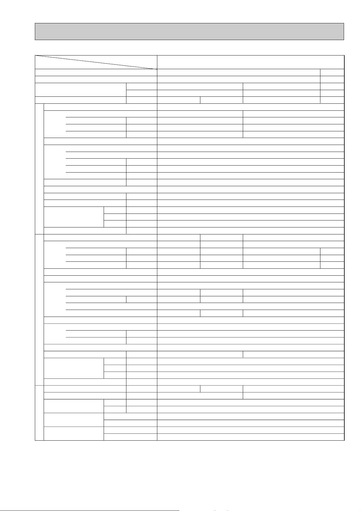
Item
Service Ref.
PK-4FLSA
2 PK-4FLSA3 PK-4FLSA4
27/19.0°C, 35/24°C
Cooling (JIS B8616)
w4
w5
33,800
9,900
5.08
37,500
11,000
4.38
33,400
9,800
3.46 / 3.63 3.40 / 3.47
PU-4VLJSA
2
Single, 50Hz, 220/240V
3.35 / 3.52
16.9 / 16.3 (90/90)
79 / 79
Three, 50Hz, 380/415V
3.29 / 3.36
5.7 / 5.5 (87/85)
38 / 38
NH56VND
2.7 2.7
NHJ56YDA NHJ56YDE
Line start
Munsell 5Y 7/1
Capillary tube
Hermetic
Plate fin coil
Propeller (direct) o 2
0.065 + 0.065
95 (3352)
—
870 (34-1/4)
295 (+24) (11-5/8 (add 1))
1258 (49-1/2)
94 (207)
9.52 (3/8)
19.05 (4/3)
Flared
Flared
w3 Max. 30m
w3 Max. 40m
PU-4TJSA
2
3, 60Hz, 220V
4.27
12.2 (92)
69
NHJ56TKA
2.7
w6 w7 w7
54 55 55
32 / 38
R-22 3.8 (8.4)
32 / 38
R-22 4.6 (10.1)
38
R-22 4.6 (10.1)
4.97
14.0(93)
69
PK-4FLSA
2 PK-4FLSA3 PK-4FLSA4
Munsell 3.4Y 7.7/0.8(White)
Plate fin coil
Line flow (direct) o 2
0.07
22 - 28 (777 - 989)
0 (direct blow)
—
Wireless remote controller & Built-in
41 - 46
20 (13/16)
1,680 (66-1/8)
235 (9-1/4)
340 (13-3/8)
28 (62)
Single, 50Hz, 220/240V
0.114 / 0.114
0.53 / 0.53 (98/90)
0.8 / 0.9
Single, 60Hz, 220V
0.114
0.53 (98)
0.8
Condition
Capacity w1
Total input w1
Service Ref.
Power supply(phase, cycle,voltage)
Input
Running current (Power factor)
Starting current
External finish
Heat exchanger
Fan(drive) o No.
Fan motor output
Airflow (Low-High)
External static pressure
Booster heater
Operation control & Thermostat
Noise level (Low-High) w2
Cond. drain conn. O.D.
Dimensions
Weight
Service Ref.
Power supply (phase, cycle, voltage)
Input
Running current (Power factor)
Starting current
External finish
Refrigerant control
Compressor
Model
Motor output
Starter type
Protection devices
Heat exchanger
Fan(drive) o No.
Fan motor output
Airflow
Defrost method
Noise level w2
Dimensions
Weight
Crankcase heater
Refrigerant Charge
Pipe size O.D.
Connection method
Between the indoor &
outdoor units
Btu/h
W
kW
kW
A(%)
A
kW
m
3
/min(CFM)
Pa(mmAq)
kW
dB
mm(in.)
mm(in.)
mm(in.)
mm(in.)
kg(lbs)
kW
A(%)
A
kW
kW
m
3
/min(CFM)
dB
mm(in.)
mm(in.)
mm(in.)
kg(lbs)
W
kg(lbs)
mm(in.)
mm(in.)
Liquid
Gas
W
D
H
W
D
H
REFRIGERANT PIPING
OUTDOOR UNIT
Indoor side
Outdoor side
Height difference
Piping length
INDOOR UNIT
Indoor, Outdoor DB/WB°C
PU-4YJSA2 PU-4YJSA3
w1 Refrigerant piping length (one way) : 5m (16ft)
w2 Noise level is measured in an unacoustic room based on JIS conditions.
w3 Up to 20m it is unnecessary to charge additional refrigerant.
w4 Indoor, Outdoor D.B./W.B. : 29/19°C, 46/24°C
w5 Cooling SSA385, 386
w6 Inner thermostat, HP switch, LP switch.
w7 Thermal switch, Reversed-phase protector, HP switch, LP switch, Thermal relay.

12
2. POWER SUPPLY & MODEL NAMES
Notes : 1. Power supply key N
……
1ph, 220V, 60Hz Y
…
3ph, 380/220, 400/230,
V(L)
…
1ph, 220, 230 240V, 50Hz 415/240V, 50Hz, 4 wires
T
……
3ph, 220V, 60Hz
2. Primary power supplies for all indoor units are single-phase.
3. ELECTRICAL SPECIFICATION
(1) Rating conditions
Series PK Indoor Unit (Single Phase)
JIS B8615, 8616
Indoor : D.B. 27°C (80°F), W.B. 19°C(66°F)
Outdoor : D.B. 35°C (95°F)
Service Ref. (Indoor unit)Power supply
1ph
3ph
1ph
3ph
220,230,240V
380/220,400/230,415/240V
220V
220V
PU-1.6VLJA2
—
—
—
PU-2VJA
2
—
PU-2NJA
1
—
PU-2.5VJA
2
—
PU-2.5NJA
1
—
PU-3VJA
2
PU-3VJB
PU-3YJA
3
PU-3YJB
PU-3NJA
1
—
PU-3VJC
PU-3VJB
PU-3YJC
PU-3YJB
PU-3NJA
1
—
PU-4VLJSA2
PU-4YJSA3
—
PU-4TJSA
2
50Hz
60Hz
Service Ref. (Outdoor unit)
PK-4FLSA
2
PK-4FLSA3
PK-4FLSA4
PK-3FLA3
PK-3FLA4
PK-3FLA5
PK-3FLA2 PK-2.5FLA2
PK-2.5FLA3
PK-2.5FLA4
PK-2FLA3 PK-1.6FLA3
Power supply (1 Phase)
Service Ref.
Current
Input
Starting current
Outdoor unit
A
kW
A
0.32
0.07
0.4
PU-1.6
0.37
0.08
0.4
PU-2
0.44
0.095
0.7
PU-2.5
0.44
0.095
0.7
PU-3
0.44
0.095
0.7
PU-3
0.53
0.114
0.8
PU-4
0.32
0.07
0.4
PU-1.6
0.37
0.08
0.4
PU-2
0.44
0.095
0.8
PU-2.5
0.44
0.095
0.8
PU-3
0.44
0.095
0.8
PU-3
0.53
0.114
0.8
PU-4
V : 220V 50Hz V : 230V 50Hz
PK-4FLSA2
PK-4FLSA3
PK-4FLSA4
PK-3FLA3
PK-3FLA4
PK-3FLA5
PK-3FLA2
PK-2.5FLA2
PK-2.5FLA3
PK-2.5FLA4
PK-2FLA3
PK-1.6FLA3
PK-4FLSA2
PK-4FLSA3
PK-4FLSA4
PK-3FLA3
PK-3FLA4
PK-3FLA5
PK-3FLA2
PK-2.5FLA2
PK-2.5FLA3
PK-2.5FLA4
PK-2FLA3
PK-1.6FLA3
Power supply (1 Phase)
Service Ref.
Current
Input
Starting current
Outdoor unit
A
kW
A
0.32
0.07
0.4
PU-1.6
0.37
0.08
0.4
PU-2
0.44
0.095
0.8
PU-2.5
0.44
0.095
0.8
PU-3
0.44
0.095
0.8
PU-3
0.53
0.114
0.8
PU-4
0.43
0.09
0.5
PU-2
0.44
0.095
0.7
PU-2.5
0.44
0.095
0.7
PU-3
0.44
0.095
0.7
PU-3
0.53
0.114
0.8
PU-4
V : 240V 50Hz N : 220V 50Hz
PK-4FLSA2
PK-4FLSA3
PK-4FLSA4
PK-3FLA3
PK-3FLA4
PK-3FLA5
PK-3FLA2
PK-2.5FLA2
PK-2.5FLA3
PK-2.5FLA4
PK-2FLA3
PK-1.6FLA3
PK-4FLSA2
PK-4FLSA3
PK-4FLSA4
PK-3FLA3
PK-3FLA4
PK-3FLA5
PK-3FLA2
PK-2.5FLA2
PK-2.5FLA3
PK-2.5FLA4
PK-2FLA3
13
DATA
5
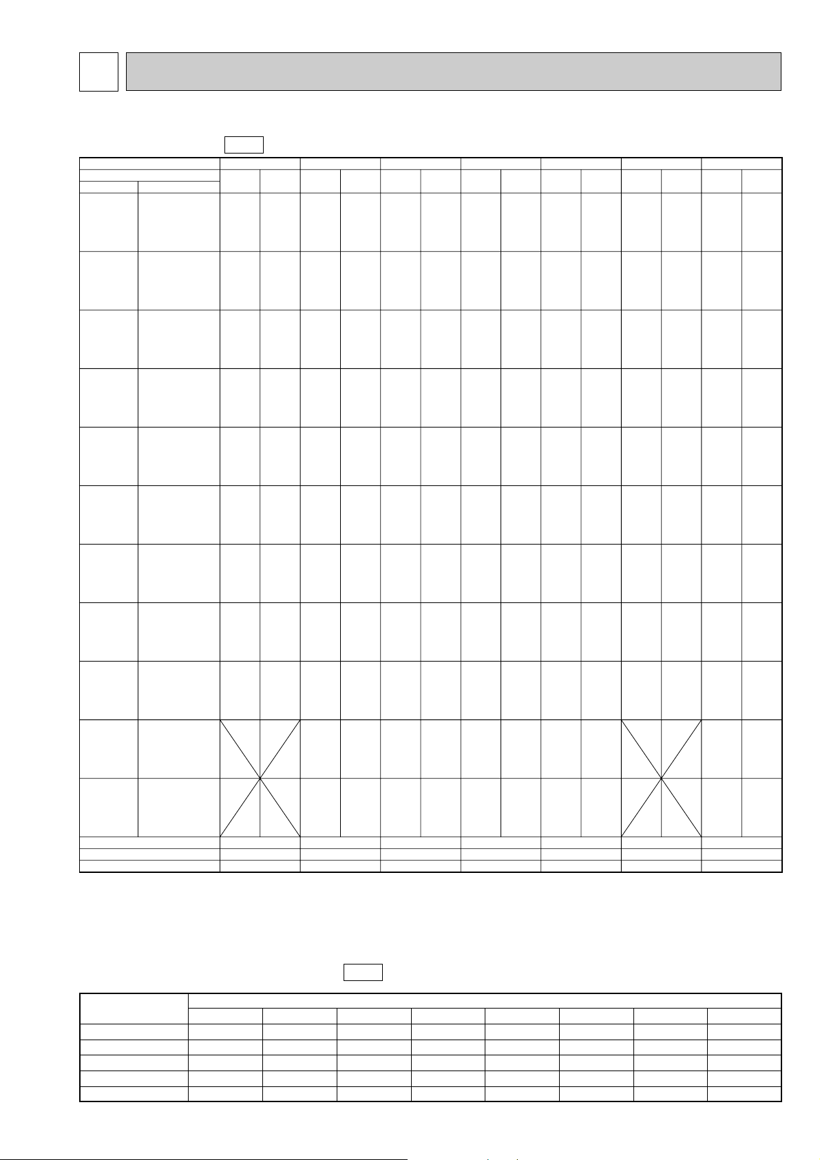
1. PERFORMANS DATA
COOLING CAPACITY
50Hz
Service Ref.
Temperature
Evaporator airflow (CMM)
Bypass factors
S.H.F. at rating conditions
13
0.18
0.81
14
0.16
0.73
20
0.11
0.81
20
0.12
0.76
20
0.12
0.73
20
0.12
0.75
28
0.12
0.73
T.C.
PK-1.6FLA
3 PK-2FLA3 PK-2.5FLA3/4 PK-3FLA2 PK-3FLA3/4/5 PK-3FLA2/3/4/5 W PK-4FLSA2/3/4
C.F.
(T.I.)
T.C. C.F.
(T.I.)
T.C. C.F.
(T.I.)
T.C. C.F.
(T.I.)
T.C. C.F.
(T.I.)
T.C. C.F.
(T.I.)
T.C. C.F.
(T.I.)
Outdoor D.B. Indoor W.B.
3.9
4.2
4.3
4.4
4.4
4.7
3.8
4.1
4.2
4.3
4.3
4.6
3.7
3.9
4.1
4.1
4.2
4.5
3.6
3.9
4.0
4.0
4.1
4.4
3.5
3.8
3.9
4.0
4.0
4.3
3.4
3.6
3.7
3.8
3.9
4.1
3.4
3.6
3.7
3.8
3.8
4.1
3.2
3.4
3.6
3.6
3.7
3.9
3.2
3.4
3.5
3.6
3.6
3.9
0.81
0.82
0.83
0.83
0.84
0.86
0.84
0.85
0.86
0.86
0.87
0.89
0.90
0.92
0.93
0.93
0.94
0.96
0.93
0.95
0.96
0.97
0.97
0.99
0.96
0.99
1.00
1.00
1.01
1.04
1.03
1.06
1.07
1.08
1.08
1.11
1.04
1.06
1.08
1.08
1.09
1.12
1.10
1.12
1.14
1.15
1.16
1.20
1.11
1.14
1.15
1.16
1.17
1.21
5.6
6.0
6.2
6.2
6.4
6.7
5.5
5.9
6.0
6.1
6.2
6.6
5.3
5.6
5.8
5.9
6.0
6.4
5.2
5.5
5.7
5.8
5.9
6.3
5.1
5.4
5.6
5.7
5.8
6.2
4.9
5.2
5.4
5.4
5.5
5.9
4.8
5.2
5.3
5.4
5.5
5.9
4.6
4.9
5.1
5.2
5.3
5.7
4.6
4.9
5.1
5.1
5.2
5.6
4.4
4.7
4.9
4.9
5.0
5.4
4.3
4.6
4.7
4.8
4.9
5.3
0.81
0.82
0.83
0.83
0.84
0.86
0.84
0.85
0.86
0.86
0.87
0.89
0.90
0.92
0.93
0.93
0.94
0.96
0.93
0.95
0.96
0.97
0.97
0.99
0.96
0.99
1.00
1.00
1.01
1.04
1.03
1.06
1.07
1.08
1.08
1.11
1.04
1.06
1.08
1.08
1.09
1.12
1.10
1.12
1.14
1.15
1.16
1.20
1.11
1.14
1.15
1.16
1.17
1.21
1.16
1.19
1.21
1.22
1.23
1.28
1.19
1.22
1.24
1.25
1.26
1.31
7.0
7.5
7.7
7.8
7.9
8.4
6.9
7.3
7.6
7.7
7.8
8.3
6.6
7.1
7.3
7.4
7.5
8.0
6.5
6.9
7.2
7.3
7.4
7.9
6.3
6.8
7.0
7.1
7.2
7.7
6.1
6.5
6.7
6.8
6.9
7.4
6.0
6.4
6.7
6.8
6.9
7.4
5.8
6.2
6.4
6.5
6.6
7.1
5.7
6.1
6.3
6.4
6.5
7.0
5.5
5.9
6.1
6.2
6.3
6.7
5.3
5.7
5.9
6.0
6.1
6.6
0.81
0.82
0.83
0.83
0.84
0.86
0.84
0.85
0.86
0.86
0.87
0.89
0.90
0.92
0.93
0.93
0.94
0.96
0.93
0.95
0.96
0.97
0.97
0.99
0.96
0.99
1.00
1.00
1.01
1.04
1.03
1.06
1.07
1.08
1.08
1.11
1.04
1.06
1.08
1.08
1.09
1.12
1.10
1.12
1.14
1.15
1.16
1.20
1.11
1.14
1.15
1.16
1.17
1.21
1.16
1.19
1.21
1.22
1.23
1.28
1.19
1.22
1.24
1.25
1.26
1.31
7.2
7.7
7.9
8.0
8.2
8.7
7.1
7.5
7.8
7.9
8.0
8.5
6.8
7.3
7.5
7.6
7.7
8.2
6.7
7.1
7.4
7.5
7.6
8.1
6.5
7.0
7.2
7.3
7.4
7.9
6.2
6.7
6.9
7.0
7.1
7.6
6.2
6.6
6.9
6.9
7.1
7.6
5.9
6.4
6.6
6.7
6.8
7.3
5.9
6.3
6.5
6.6
6.7
7.2
5.6
6.0
6.2
6.3
6.5
6.9
5.5
5.9
6.1
6.2
6.3
6.8
0.81
0.82
0.83
0.83
0.84
0.86
0.84
0.85
0.86
0.86
0.87
0.89
0.90
0.92
0.93
0.93
0.94
0.96
0.93
0.95
0.96
0.97
0.97
0.99
0.96
0.99
1.00
1.00
1.01
1.04
1.03
1.06
1.07
1.08
1.08
1.11
1.04
1.06
1.08
1.08
1.09
1.12
1.10
1.12
1.14
1.15
1.16
1.20
1.11
1.14
1.15
1.16
1.17
1.21
1.16
1.19
1.21
1.22
1.23
1.28
1.19
1.22
1.24
1.25
1.26
1.31
0.81
0.82
0.83
0.83
0.84
0.86
0.84
0.85
0.86
0.86
0.87
0.89
0.90
0.92
0.93
0.93
0.94
0.96
0.93
0.95
0.96
0.97
0.97
0.99
0.96
0.99
1.00
1.00
1.01
1.04
1.03
1.06
1.07
1.08
1.08
1.11
1.04
1.06
1.08
1.08
1.09
1.12
1.10
1.12
1.14
1.15
1.16
1.20
1.11
1.14
1.15
1.16
1.17
1.21
7.9
8.4
8.7
8.8
9.0
9.5
7.8
8.3
8.5
8.6
8.8
9.4
7.5
8.0
8.2
8.3
8.5
9.0
7.3
7.8
8.1
8.2
8.3
8.9
7.2
7.6
7.9
8.0
8.2
8.7
6.8
7.3
7.6
7.7
7.8
8.3
6.8
7.3
7.5
7.6
7.8
8.3
6.5
7.0
7.2
7.3
7.5
8.0
6.4
6.9
7.1
7.2
7.4
7.9
6.2
6.6
6.9
6.9
7.1
7.6
6.0
6.5
6.7
6.8
6.9
7.4
7.5
8.0
8.3
8.4
8.5
9.0
7.4
7.8
8.1
8.2
8.4
8.9
7.1
7.6
7.8
7.9
8.1
8.6
7.0
7.4
7.7
7.8
7.9
8.4
6.8
7.3
7.5
7.6
7.7
8.3
6.5
6.9
7.2
7.3
7.4
7.9
6.5
6.9
7.1
7.2
7.4
7.9
6.2
6.6
6.8
6.9
7.1
7.6
6.1
6.5
6.8
6.9
7.0
7.5
9.8
10.5
10.8
10.9
11.1
11.8
9.6
10.2
10.6
10.7
10.9
11.6
9.3
9.9
10.2
10.3
10.5
11.2
9.1
9.7
10.0
10.2
10.3
11.0
8.9
9.5
9.8
9.9
10.1
10.8
8.5
9.1
9.4
9.5
9.7
10.3
8.4
9.0
9.3
9.5
9.6
10.3
8.1
8.6
8.9
9.1
9.3
9.9
8.0
8.6
8.9
9.0
9.2
9.8
7.6
8.2
8.5
8.6
8.8
9.4
7.4
8.0
8.3
8.4
8.6
9.2
21˚C
(69.8˚ F)
16˚C
18˚C
19˚C
19.4˚C
20˚C
22˚C
(60.8˚ F)
(64.4˚ F)
(66.2˚ F)
(67˚ F)
(68˚ F)
(71.6˚ F)
16˚C
18˚C
19˚C
19.4˚C
20˚C
22˚C
(60.8˚ F)
(64.4˚ F)
(66.2˚ F)
(67˚ F)
(68˚ F)
(71.6˚ F)
16˚C
18˚C
19˚C
19.4˚C
20˚C
22˚C
(60.8˚ F)
(64.4˚ F)
(66.2˚ F)
(67˚ F)
(68˚ F)
(71.6˚ F)
16˚C
18˚C
19˚C
19.4˚C
20˚C
22˚C
(60.8˚ F)
(64.4˚ F)
(66.2˚ F)
(67˚ F)
(68˚ F)
(71.6˚ F)
16˚C
18˚C
19˚C
19.4˚C
20˚C
22˚C
(60.8˚ F)
(64.4˚ F)
(66.2˚ F)
(67˚ F)
(68˚ F)
(71.6˚ F)
16˚C
18˚C
19˚C
19.4˚C
20˚C
22˚C
(60.8˚ F)
(64.4˚ F)
(66.2˚ F)
(67˚ F)
(68˚ F)
(71.6˚ F)
16˚C
18˚C
19˚C
19.4˚C
20˚C
22˚C
(60.8˚ F)
(64.4˚ F)
(66.2˚ F)
(67˚ F)
(68˚ F)
(71.6˚ F)
16˚C
18˚C
19˚C
19.4˚C
20˚C
22˚C
(60.8˚ F)
(64.4˚ F)
(66.2˚ F)
(67˚ F)
(68˚ F)
(71.6˚ F)
16˚C
18˚C
19˚C
19.4˚C
20˚C
22˚C
(60.8˚ F)
(64.4˚ F)
(66.2˚ F)
(67˚ F)
(68˚ F)
(71.6˚ F)
16˚C
18˚C
19˚C
19.4˚C
20˚C
22˚C
(60.8˚ F)
(64.4˚ F)
(66.2˚ F)
(67˚ F)
(68˚ F)
(71.6˚ F)
16˚C
18˚C
19˚C
19.4˚C
20˚C
22˚C
(60.8˚ F)
(64.4˚ F)
(66.2˚ F)
(67˚ F)
(68˚ F)
(71.6˚ F)
25˚C
(77˚ F)
30˚C
(86˚ F)
32.2˚C
(90˚ F)
35˚C
(95˚ F)
40˚C
(104˚ F)
40.6˚C
(105˚ F)
45˚C
(113˚ F)
46˚C
(115˚ F)
50˚C
(69.8˚ F)
52˚C
(125.5˚ F)
Notes: 1. T.C.: Total capacity (kW)
…
(kcal/h)=(kW)x860, (Btu/h)=4x(kW)x860
C.F.(T.I.) : Correction factors of Total input(Indoor unit input + Outdoor unit input)
2. (°F)=32+9/5(°C)
3. Guaranteed operating range(cooling)
{
Lower limit … Indoor : D.B. 21°C(70°F), W.B. 15.5°C(60°F), Outdoor : D.B. 21°C(70°F).
Upper limit … Indoor : D.B. 35°C(95°F), W.B. 22.5°C(72.5°F), Outdoor : D.B. 46°C(115°F)…VLJ, VJB, YJB. W
W Outdoor : D.B. 52°C(125.5°F)…VJA, YJA.
COOLING CAPACITY correction factors
50Hz
Service Ref.
Refrigerant piping length (one way)
5m (16ft)
1.0
1.0
1.0
1.0
1.0
10m (33ft)
0.992
0.985
0.983
0.978
0.984
15m (49ft)
0.987
0.975
0.972
0.962
0.974
20m (66ft)
0.982
0.964
0.961
0.948
0.964
25m (82ft)
—
0.954
0.951
0.934
0.954
30m (98ft)
—
0.944
0.940
0.921
0.944
35m (115ft)
—
—
—
—
0.914
40m (13ft)
—
—
—
—
0.902
PK-1.6FLA3
PK-2FLA3
PK-2.5FLA2/3/4
PK-3FLA2/3/4/5
PK-4FLSA2/3/4
W Outdoor unit
PU-3JB
14
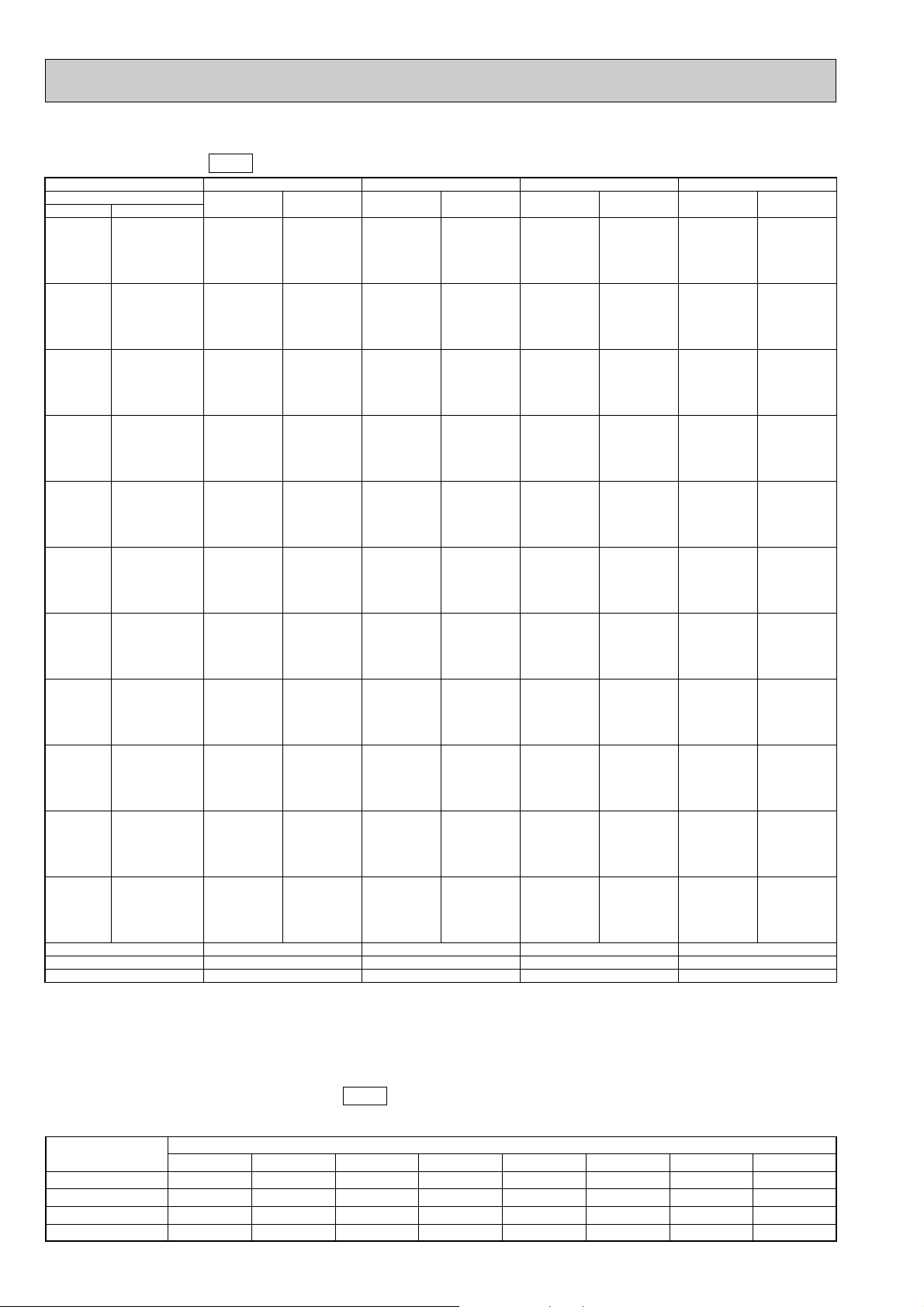
COOLING CAPACITY
60Hz
COOLING CAPACITY correction factors
60Hz
Refrigerant piping length (one way)
Service Ref.
5m (16ft)
1.0
1.0
1.0
1.0
10m (33ft)
0.985
0.978
0.971
0.980
15m (49ft)
0.975
0.963
0.950
0.966
20m (66ft)
0.964
0.948
0.931
0.952
25m (82ft)
0.954
0.934
0.913
0.939
30m (98ft)
0.944
0.921
0.896
0.926
35m (115ft)
—
—
—
0.941
40m (131ft)
—
—
—
0.902
PK-2FLA
3
PK-2.5FLA2/3/4
PK-3FLA2/3/4/5
PK-4FLSA2/3/4
Notes: 1. T.C.: Total capacity (kW)
…
(kcal/h)=(kW)x860, (Btu/h)=4x(kW)x860
C.F.(T.I.) : Correction factors of Total input(Indoor unit input + Outdoor unit input)
2. (°F)=32+9/5(°C)
3. Guaranteed operating range(cooling)
{
Lower limit … Indoor : D.B. 21°C(70°F), W.B. 15.5°C(60°F), Outdoor : D.B. 21°C(70°F).
Upper limit … Indoor : D.B. 35°C(95°F), W.B. 22.5°C(72.5°F), Outdoor : D.B. 52°C(125.5°F).
Service Ref.
Temperature
Evaporator airflow (CMM)
Bypass factors
S.H.F. at rating conditions
14
0.16
0.73
20
0.12
0.78
20
0.13
0.78
28
0.14
0.73
PK-2FLA
3 PK-2.5FLA3/4 PK-3FLA2/3/4/5 PK-4FLSA2/3/4
T.C. C.F.
(T.I.)
T.C. C.F.
(T.I.)
T.C. C.F.
(T.I.)
T.C. C.F.
(T.I.)
Outdoor D.B.
21˚C
(69.8˚ F)
16˚C
18˚C
19˚C
19.4˚C
20˚C
22˚C
(60.8˚ F)
(64.4˚ F)
(66.2˚ F)
(67˚ F)
(68˚ F)
(71.6˚ F)
16˚C
18˚C
19˚C
19.4˚C
20˚C
22˚C
(60.8˚ F)
(64.4˚ F)
(66.2˚ F)
(67˚ F)
(68˚ F)
(71.6˚ F)
16˚C
18˚C
19˚C
19.4˚C
20˚C
22˚C
(60.8˚ F)
(64.4˚ F)
(66.2˚ F)
(67˚ F)
(68˚ F)
(71.6˚ F)
16˚C
18˚C
19˚C
19.4˚C
20˚C
22˚C
(60.8˚ F)
(64.4˚ F)
(66.2˚ F)
(67˚ F)
(68˚ F)
(71.6˚ F)
16˚C
18˚C
19˚C
19.4˚C
20˚C
22˚C
(60.8˚ F)
(64.4˚ F)
(66.2˚ F)
(67˚ F)
(68˚ F)
(71.6˚ F)
16˚C
18˚C
19˚C
19.4˚C
20˚C
22˚C
(60.8˚ F)
(64.4˚ F)
(66.2˚ F)
(67˚ F)
(68˚ F)
(71.6˚ F)
16˚C
18˚C
19˚C
19.4˚C
20˚C
22˚C
(60.8˚ F)
(64.4˚ F)
(66.2˚ F)
(67˚ F)
(68˚ F)
(71.6˚ F)
16˚C
18˚C
19˚C
19.4˚C
20˚C
22˚C
(60.8˚ F)
(64.4˚ F)
(66.2˚ F)
(67˚ F)
(68˚ F)
(71.6˚ F)
16˚C
18˚C
19˚C
19.4˚C
20˚C
22˚C
(60.8˚ F)
(64.4˚ F)
(66.2˚ F)
(67˚ F)
(68˚ F)
(71.6˚ F)
16˚C
18˚C
19˚C
19.4˚C
20˚C
22˚C
(60.8˚ F)
(64.4˚ F)
(66.2˚ F)
(67˚ F)
(68˚ F)
(71.6˚ F)
16˚C
18˚C
19˚C
19.4˚C
20˚C
22˚C
(60.8˚ F)
(64.4˚ F)
(66.2˚ F)
(67˚ F)
(68˚ F)
(71.6˚ F)
25˚C
(77˚ F)
30˚C
(86˚ F)
32.2˚C
(90˚ F)
35˚C
(95˚ F)
40˚C
(104˚ F)
40.6˚C
(105˚ F)
45˚C
(113˚ F)
46˚C
(115˚ F)
50˚C
(69.8˚ F)
52˚C
(125.5˚ F)
Indoor W.B.
5.5
5.8
6.0
6.1
6.2
6.6
5.3
5.7
5.9
6.0
6.1
6.5
5.2
5.5
5.7
5.7
5.9
6.2
5.1
5.4
5.6
5.6
5.8
6.1
4.9
5.3
5.5
5.5
5.6
6.0
4.7
5.0
5.2
5.3
5.4
5.8
4.7
5.0
5.2
5.3
5.4
5.7
4.5
4.8
5.0
5.0
5.1
5.5
4.4
4.8
4.9
5.0
5.1
5.5
4.2
4.6
4.7
4.8
4.9
5.2
4.1
4.5
4.6
4.7
4.8
5.1
7.2
7.6
7.9
8.0
8.1
8.6
7.0
7.5
7.7
7.8
8.0
8.5
6.8
7.2
7.4
7.5
7.7
8.2
6.6
7.1
7.3
7.4
7.5
8.0
6.5
6.9
7.2
7.2
7.4
7.9
6.2
6.6
6.8
6.9
7.1
7.5
6.2
6.6
6.8
6.9
7.0
7.5
5.9
6.3
6.5
6.6
6.8
7.2
5.8
6.2
6.5
6.6
6.7
7.2
5.6
6.0
6.2
6.3
6.4
6.9
5.4
5.8
6.1
6.2
6.3
6.7
8.0
8.6
8.8
8.9
9.1
9.6
7.8
8.4
8.6
8.7
8.9
9.5
7.6
8.1
8.3
8.4
8.6
9.1
7.4
7.9
8.2
8.3
8.4
9.0
7.3
7.7
8.0
8.1
8.3
8.8
6.9
7.4
7.7
7.8
7.9
8.4
6.9
7.4
7.6
7.7
7.9
8.4
6.6
7.1
7.3
7.4
7.6
8.1
6.5
7.0
7.2
7.3
7.5
8.0
6.2
6.7
6.9
7.0
7.2
7.7
6.1
6.5
6.8
6.9
7.0
7.5
11.0
11.8
12.1
12.3
12.5
13.2
10.8
11.5
11.9
12.0
12.2
13.0
10.4
11.1
11.4
11.6
11.8
12.6
10.2
10.9
11.3
11.4
11.6
12.4
10.0
10.6
11.0
11.1
11.4
12.1
9.5
10.2
10.5
10.7
10.9
11.6
9.5
10.1
10.5
10.6
10.8
11.6
9.1
9.7
10.0
10.2
10.4
11.1
9.0
9.6
9.9
10.1
10.3
11.0
8.6
9.2
9.5
9.7
9.9
10.6
8.4
9.0
9.3
9.5
9.7
10.4
0.81
0.82
0.83
0.83
0.84
0.86
0.84
0.85
0.86
0.86
0.87
0.89
0.90
0.92
0.93
0.93
0.94
0.96
0.93
0.95
0.96
0.97
0.97
0.99
0.96
0.99
1.00
1.00
1.01
1.04
1.03
1.06
1.07
1.08
1.08
1.11
1.04
1.06
1.08
1.08
1.09
1.12
1.10
1.12
1.14
1.15
1.16
1.20
1.11
1.14
1.15
1.16
1.17
1.21
1.16
1.19
1.21
1.22
1.23
1.28
1.19
1.22
1.24
1.25
1.26
1.31
0.81
0.82
0.83
0.83
0.84
0.86
0.84
0.85
0.86
0.86
0.87
0.89
0.90
0.92
0.93
0.93
0.94
0.96
0.93
0.95
0.96
0.97
0.97
0.99
0.96
0.99
1.00
1.00
1.01
1.04
1.03
1.06
1.07
1.08
1.08
1.11
1.04
1.06
1.08
1.08
1.09
1.12
1.10
1.12
1.14
1.15
1.16
1.20
1.11
1.14
1.15
1.16
1.17
1.21
1.16
1.19
1.21
1.22
1.23
1.28
1.19
1.22
1.24
1.25
1.26
1.31
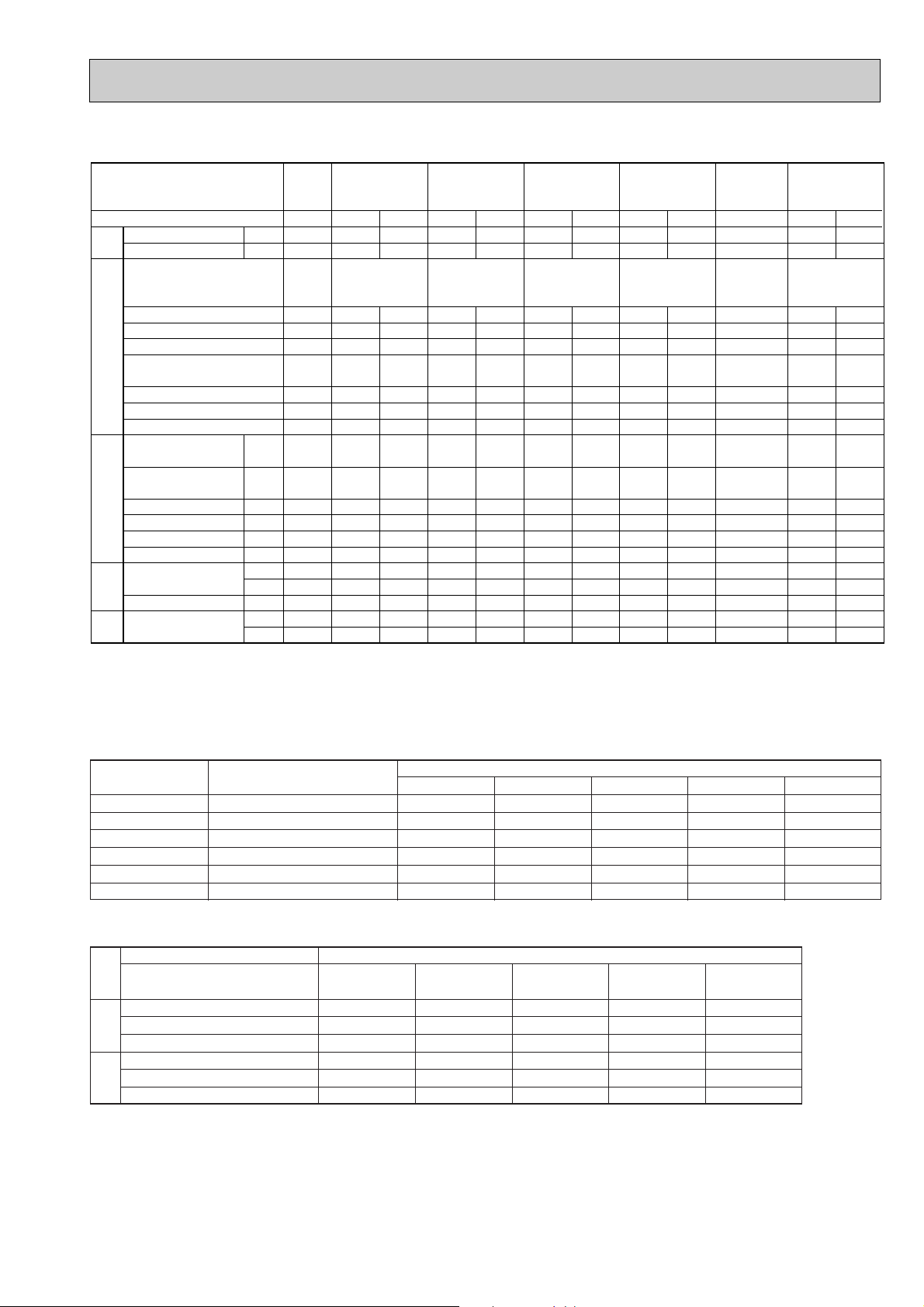
15
Service Ref.
MODE
W
kW
Mpa
(o/f)
Mpa
(o/f)
˚C
˚C
˚C
m
D.B.˚C
W.B.˚C
D.B.˚C
D.B.˚C
W.B.˚C
CoolingCoolingCoolingCoolingCoolingCoolingCoolingCoolingCooling
PK-3FLA
3
PK-3FLA
4
PK-3FLA
5
PK-3FLA
3
PK-3FLA
4
PK-3FLA
5
PK-2.5FLA
2
PK-2.5FLA
3
PK-2.5FLA
4
PK-2.5FLA
2
PK-2.5FLA
3
PK-2.5FLA
4
PK-2FLA
3
PK-2FLA
3
PK-1.6
FLA
3
PK-1.6
FLA
3
PK-3FLA
2
PK-3FLA
2
Electrical circuitRefrigerant circuit
Indoor
side
Outdoor
side
Capacity
Input
Indoor unit
Service Ref.
Phase , Hz
Volts
Amperes
Outdoor unit
Service Ref.
Phase , Hz
Volts
Amperes
Discharge pressure
Suction pressure
Discharge temperature
Condensing temperature
Suction temperature
Refrigerant pipe length
Intake air
temperature
Discharge air temperature
Intake air
temperature
Total
7900
3.28
1 , 50
220
0.44
PU-3
VJC
1 , 50
220
15.1
1.99
(20.3)
0.47
(4.79)
86
51
6
5
27
19
13.0
35
24
Cooling
PK-3FLA
2
PK-3FLA3
PK-3FLA
4
PK-3FLA
5
PK-3FLA
2
PK-3FLA3
PK-3FLA
4
PK-3FLA
5
7500
3.28
1 , 50
220
0.44
PU-3
VJB
1 , 50
220
12.4
1.94
(19.8)
0.48
(4.85)
76
51.4
5
5
27
19
13.4
35
24
6900
4.19
1 , 60
220
0.44
PU-3
NJA
1
1 , 60
220
20.9
2.07
(21.1)
0.44
(4.49)
70
53
4
5
29
19
13.2
46
24
7200
3.28
1 , 50
220
0.44
PU-3
VJA
2
1 , 50
220
15.1
1.99
(20.3)
0.47
(4.79)
62
51
6
5
27
19
13.7
35
24
6900
4.19
1 , 60
220
0.44
PU-3
NJA
1
1 , 60
220
20.9
2.07
(21.1)
0.44
(4.49)
70
53
4
5
29
19
13.2
46
24
7000
2.56
1 , 50
220
0.44
PU-2.5
VJA
2
1 , 50
220
11.4
2.05
(20.9)
0.47
(4.79)
74.3
52
10.3
5
27
19
14.1
35
24
6650
3.54
1 , 60
220
0.44
PU-2.5
NJA
1
1 , 60
220
15.8
2.13
(21.7)
0.44
(4.49)
87
54
10
5
29
19
14.1
46
24
5600
2.52
1 , 50
220
0.37
PU-2
VJA
2
1 , 50
220
11.3
1.98
(20.2)
0.46
(4.69)
66
52
3
5
27
19
13.4
35
24
3900
1.49
1 , 50
220
0.32
PU-1.6
VLJA
2
1 , 50
220
6.7
1.89
(19.3)
0.5
(5.1)
84
50
9
5
27
19
15.4
35
24
4600
2.60
1 , 60
220
0.42
PU-2
NJA
1
1 , 60
220
13.6
1.96
(20.0)
0.47
(4.79)
66
52
5
5
29
19
13.5
46
24
CoolingCooling
PK-4FLSA
2
PK-4FLSA
3
PK-4FLSA
4
PK-4FLSA
2
PK-4FLSA
3
PK-4FLSA
4
9800
3.46
1 , 50
220
0.53
PU-4
YJSA
3
3 , 50
220
5.7
1.80
(18.4)
0.48
(4.89)
65
49
6
5
27
19
13.9
35
24
9900
5.08
1 , 60
220
0.53
PU-4
TJSA
3
3 , 60
220
14.0
1.93
(19.7)
0.45
(4.59)
74
52
5
5
29
19
13.2
46
24
2. STANDARD OPERATION DATA
Total Electrical circuit Refrigerant circuit Indoor side Outdoor side
The unit of pressure has been changed to Mpa on the international system of unit(SI unit system).
The converted score against the traditional unit system can be gotten according to the formula below.
1(Mpa)=10.2(O/F·G)
3. ADDITIONAL REFRIGERANT CHARGE (R-22
…
kg(lbs))
4. OUTLET AIR SPEED AND COVERAGE RANGE
w The air coverage range is the value up to the position where the air speed is 0.25m/sec. when air is blown out horizontally
from the unit at the Hi notch position/
The coverage range should be used only as a general guideline since it varies according to the size of the room and furni-
ture inside the room.
Service Ref.
Outdoor unit precharged (kg)
(up to 20m)
Refrigerant piping length (one way)
PK-1.6FLA3
PK-2FLA3
PK-2.5FLA2/3/4
PK-3FLA2
PK-3FLA3/4/5
PK-4FLSA2/3/4
VL---1.3,
V---1.79, N---1.9
V---2.4, N---2.4
V---3.08, Y---2.88, N---3.5
V---2.8, Y---2.8, N---3.5
VL---3.8, Y---4.6, T---4.6
20m (66ft)
0
0
0
0
0
0
25m (82ft)
—
0.06(0.13)
0.06(0.13)
0.06(0.13)
0.06(0.13)
0.15(0.33)
30m (98ft)
—
0.12(0.26)
0.12(0.26)
0.12(0.26)
0.12(0.26)
0.30(0.66)
35m (115ft)
—
—
—
—
—
0.45(0.99)
40m (131ft)
—
—
—
—
—
0.6(1.32)
Airflow
Air speed
Coverage range
w
Airflow
Air speed
Coverage rangew
m
3
/min
m/sec.
m(ft)
m
3
/min
m/sec.
m(ft)
13
4.0
9.1(30)
—
—
—
60Hz 50Hz
Frequency
Configuration Wall mounted
Model PK-1.6FLA
14
4.3
9.8(32)
14
4.3
9.8(32)
PK-2FLA
20
4.9
12.4(41)
20
4.9
12.4(41)
PK-2.5FLA
20
4.9
12.4(41)
20
4.9
12.4(41)
PK-3FLA
28
5.4
15.3(50)
28
5.4
15.3(50)
PK-4FLSA
16
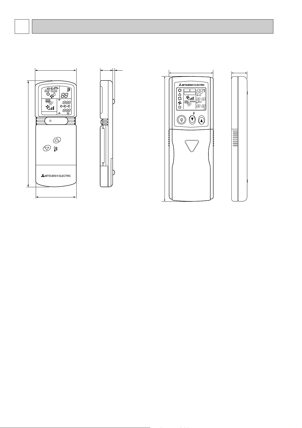
6
OUTLINES AND DIMENSIONS
PK-1.6FLA3
PK-2FLA3
PK-2.5FLA2, PK-2.5FLA3
PK-3FLA2, PK-3FLA3, PK-3FLA4
PK-4FLSA2, PK-4FLSA3
PK-2.5FLA4
PK-3FLA5
PK-4FLSA4
TEMP
ON / OFF
NOT AVAILABLE
AM
PM
AM
PM
˚C
153
57 18 3
55
58
162
19
ON/OFF TEMP
MODEL SELECT
NOT AVAILABLE
CHECK
TEST RUN
˚C
AMPM
AMPM
Unit : mm
1. REMOTE CONTROLLER

17
Unit : mm
Pipe position
Left side
Lequid pipe
Gas pipe
Service space required
around indoor unit
(100 for left-hand
side piping)
Right side
130 or less
2 tapping screws
for installation plate
(Necessary clearance for
Unit installation)
Drain pipe
Front
50 or more
2-unit hangers
Unit cennter
Liquid pipe position
Gas pipe position
(Width of unit)
Knock out hole for
left-rear piping
Knock out hole for
left-rear piping
Rear piping hole
2 X5 - 2.9 hole
for tapping screw
Details of installation plate
1 Sleeves are available on
the market.
2 This size shows the lower
end of through hole.
Sleeve
90 90~ 100
Through hole
150 or more
Knock out hole for
left-hand side piping
Ref.pipes & drain pipe
215
168
2134
8
20
70
300
47
30 or more
180 or more
80
25
35
60
Left side
Air intake
Front
1250
449 Air intake
Auto vanes
Service panel for
power supply connection
449 Air intake
968 Air intake
48
236
227
Right side
Terminal block
Right side
Knock out hole for right piping
(2:1)
Knock-out hole for
night-hand side piping
Knock out hole
for piping
8
60
Knock out hole for piping
Terminal block for control
Terminal block & pipe position
Drainage
Drainage(Flexible hole: length 1200)
Liquid pipe
Bass pipe
Lower side
Terminal block for
power supply
Knock out hole for under-piping
15 or less
bolt
Installation bolt position
200
B
B
A
A
8
8
60
91
65
20
70
(2:1)
70
Lower side
976
16 -louvers
(manual)
500
479 Air outlet479 Air outlet
26
173
223
222
143
553
635
685
170
190
200
1100
50
1
Knock out hole
for piping
1
2
2
3/8F
5/8F
0
35
53
80
130
177
227
(178)
(375)
447
190
13- 14
hole
60
1250
330
80
0
53
68- 5
hole
277
Tapping screw
300
491
476
450
405
323
276
229
179
150
70
24
0
70
150
174
224
271
318
374
9
73
405
450
476
486
625
(Height ut unit)
85
45
286X
2
R52.5R52.5
R52.5R52.5
w
w
2. INDOOR UNIT
PK-1.6FLA
3
PK-2FLA
3

18
Unit : mm
235
45
235
45
235
45
235
62.5
13
58
42
340
197
Top
Front
Right side
Left side
1400
1090
Air intake
235
C
Knock out hole for right piping
Refrigerant pipe. Drain pipe
Knock out hole for
left piping
Drain hose for
left-hand side piping
Drain hose
Lower side
Auto vane
(Gas pipe)
Drain hose
Bolt
Gas pipe
15
Terminal block for power supply
Terminal block for control
(Liquid pipe)
Liquid pipe 9.52(3/8F)
Gas pipe 15.88(5/8F)
Liquid pipe
A
30
32
39
98
37
74
439
100
30
37
74
4
2980
280
3030
18430
60
10
39
37
65
100
AB C
Knock out hole for piping
25
1110
183
240
B
1120
552
55
120
107
111
Air outlet
552
Air outlet
Change vane (manual)
Under panel
Removable at left-hand
side piping
Knock out hole for under-piping
Refrigerant pipe. Drain pipe
Rear piping opening
Range for left rear piping opening
12-ø6 hole for
tapping screw
66-ø6 hole for
tapping screw
Wall fixture
Unit center
32-ø12 hole for bolt
225
18
18
91
900
990
455
285
245
19
240 280 314
610
90
Drainage range
on left-hand side
Drainage range
on right-hand side
10 91=(910)
180
PK-2.5FLA
2
, PK-2.5FLA
3
, PK-2.5FLA
4
PK-3FLA
2
, PK-3FLA
3
, PK-3FLA
4
, PK-3FLA
5
 Loading...