


Mitsubishi PLA-P1.6KA.UK, PLA-P2KA.UK, PLA-P2.5KA.UK, PLA-P1.6KA1.UK, PLA-P2KA1.UK Service Manual
...SPLIT-TYPE AIR CONDITIONERS
No. OC240
REVISED EDITION-A
TECHNICAL & SERVICE MANUAL
Series PLA |
|
Ceiling Cassettes |
|
|
|
R407C |
|
||
Indoor unit |
|
|
|
|
|
|
|
||
[Model names] |
[Service Ref.] |
|||
PLA-P1.6KA |
PLA-P1.6KA.UK |
|||
|
|
PLA-P1.6KA1.UK |
||
PLA-P2KA |
PLA-P2KA.UK |
|||
|
|
PLA-P2KA1.UK |
||
PLA-P2.5KA |
PLA-P2.5KA.UK |
|||
|
|
PLA-P2.5KA1.UK |
||
•PLH-P1.6KA1.UK,PLH-P2KA1.UK and PLH-P2.5KA1.UK are REVISED EDITION-A.
Outdoor units PU(H)- P1.6,2,2.5VGAA.UK and PU(H)- P1.6,2,2.5YGAA.UK which are connected to those indoor units are also added in it.
•Please void OC240.
•Refer to the OCT03 REVISED EDITION-C as for control relation. This manual does not cover outdoor units. When servicing them, please refer to the service manual No.OC180 REVISED EDITION-A OC261 and this manual in a set.
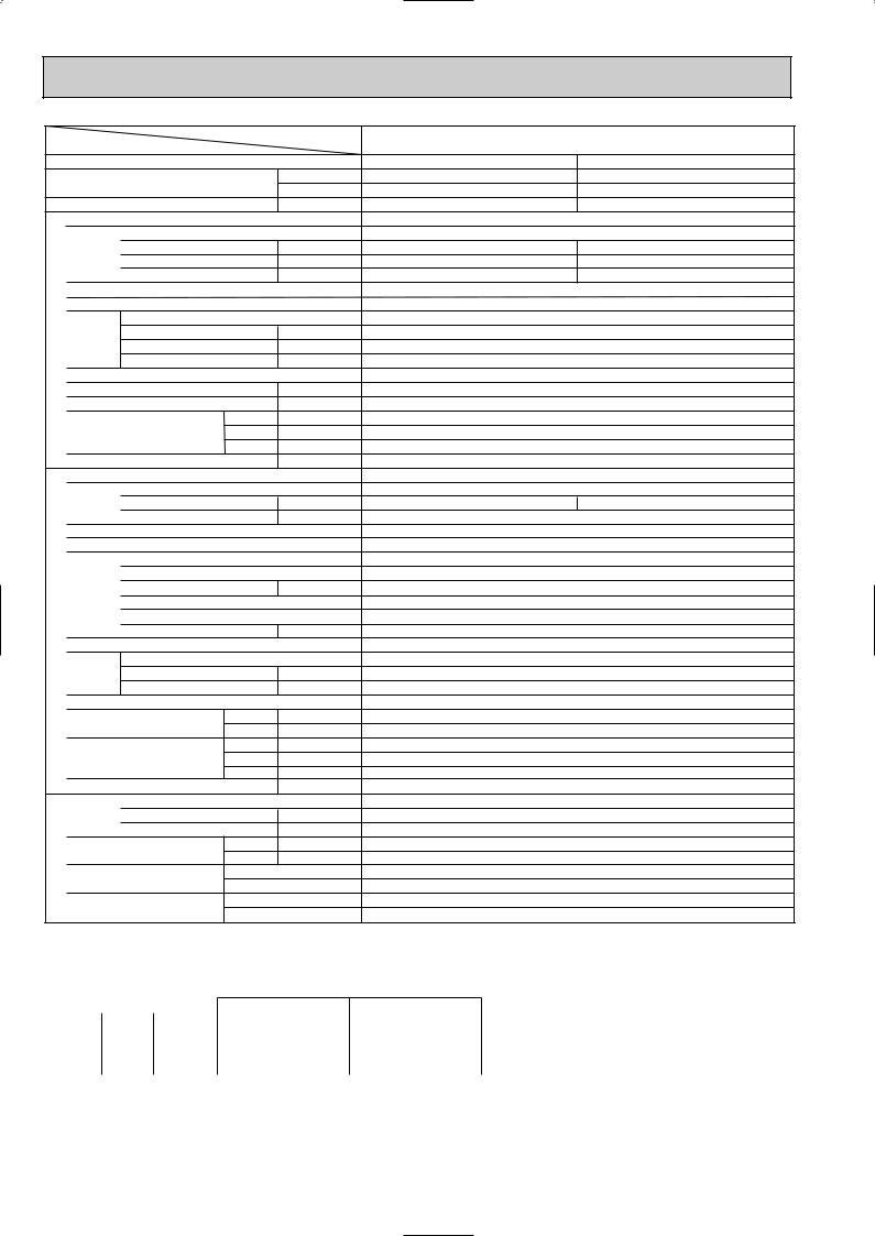
INDOOR UNIT
FILTER
CENTRALLY CONTROLLED |
1Hr. |
|
|
CHECK MODE |
ON OFF |
|
˚C |
CHECK |
CLOCK |
|
|
TEST RUN |
|
|
FILTER |
|
˚C |
|
CHECK MODE |
STAND BY |
|
TEST RUN |
|
DEFROST |
ERROR CODE |
NOT AVAILABLE |
FUNCTION |
CONTENTS
1.TECHNICAL CHANGES ············
2.COMBINATION OF INDOOR AND OUTDOOR UNITS··2
3.SAFETY PRECAUTION ·············
4.PART NAMES AND FUNCTIONS ········
5.SPECIFICATIONS ···············
6.DATA ·····················
7.OUTLINES AND DIMENSIONS ·········
8.WIRING DIAGRAM ················
9.REFRIGERANT SYSTEM DIAGRAM·········
10.TROUBLESHOOTING ·············
11.DISASSEMBLY PROCEDURE ··········
12.PARTS LIST ··················
13.OPTIONAL PARTS ···············
 TEMP.
TEMP.  ON/OFF
PLA-P1.6,2,2.5KA.UK |
PLA-P1.6,2,2.5KA1.UK |
REMOTE CONTROLLER
1 
 TECHNICAL CHANGES
PLA-P1.6KA.UK PLA-P1.6KA1.UK |
PLA-P2KA.UK PLA-P2KA1.UK |
PLA-P2.5KA.UK PLA-P2.5KA1.UK |
|
●REMOTE CONTROLLER has changed.(PAR-S27A-E PAR-20MAA-E)
●Outdoor units which are connected to PLA-P·KA.UK and PLA-P·KA1.UK have been added.
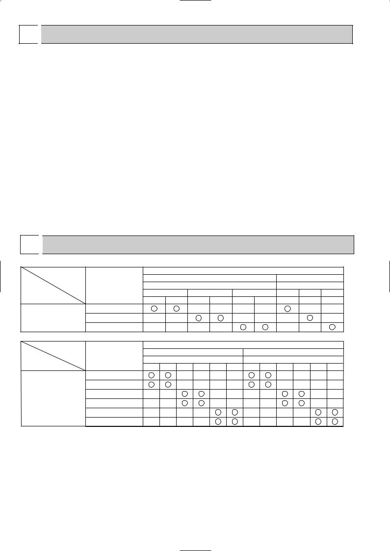
2 
 COMBINATION OF INDOOR AND OUTDOOR UNITS
|
|
|
|
|
|
Outdoor unit |
|
|
|
|
|
Indoor unit |
|
|
Heat pump type |
|
Cooling only type |
||||
|
|
|
PUH-P |
|
|
|
PU-P |
|
||
|
|
|
1.6 |
|
2 |
|
2.5 |
1.6 |
2 |
2.5 |
|
|
VGA |
YGA |
VGA |
YGA |
VGA1 |
YGA1 |
VGA |
VGA |
VGA1 |
Heat pump without |
PLA-P1.6KA.UK |
|
|
— |
— |
— |
— |
|
— |
— |
electric heater or |
PLA-P2KA.UK |
— |
— |
|
|
— |
— |
— |
|
— |
Cooling only |
PLA-P2.5KA.UK |
— |
— |
— |
— |
|
|
— |
— |
|
|
|
|
|
|||||||
|
|
|
Heat pump type |
Outdoor unit |
|
|
|
|
|||||
|
Indoor unit |
|
|
|
Cooling only type |
|
|||||||
|
|
PUH-P•GAA.UK |
|
|
PU-P•GAA.UK |
|
|||||||
|
|
1.6V |
1.6Y |
2V |
2Y |
2.5V |
2.5Y |
1.6V |
1.6Y |
2V |
2Y |
2.5V |
2.5Y |
Heat pump without |
PLA-P1.6KA.UK |
|
|
— |
— |
— |
— |
|
|
— |
— |
— |
— |
electric heater |
PLA-P1.6KA1.UK |
|
|
— |
— |
— |
— |
|
|
— |
— |
— |
— |
or |
PLA-P2KA.UK |
— |
— |
|
|
— |
— |
— |
— |
|
|
— |
— |
Cooling only |
|
|
|
|
|||||||||
PLA-P2KA1.UK |
— |
— |
|
|
— |
— |
— |
— |
|
|
— |
— |
|
|
|
|
|
|
|||||||||
|
PLA-P2.5KA.UK |
— |
— |
— |
— |
|
|
— |
— |
— |
— |
|
|
|
PLA-P2.5KA1.UK |
— |
— |
— |
— |
|
|
— |
— |
— |
— |
|
|
2

3 SAFETY PRECAUTION
Cautions for using with the outdoor unit which adopts R407C refrigerant.
· Do not use the existing refrigerant piping.
-The old refrigerant and refrigerant oil in the existing piping contains a large amount of chlorine which may cause the refrigerant oil of the new unit to deteriorate.
· Do not use copper pipes which are broken, deformed or discolour .
In addition, be sure that the inner surfaces of the pipes are clean, free of hazardous sulphur and oxides, or have no dust / dirt, shaving particles, oils, moisture or any other contamination.
-If there is a large amount of residual oil (hydraulic oil, etc.) inside the piping and joints, deterioration of the refrigerant oil will result.
·Store the piping to be used during installation indoors and keep both ends of the piping sealed until just before brazing. (Store elbows and other joints in a plastic bag.)
-If dust, dirt, or water enters the refrigerant cycle, deterioration of the oil and compressor trouble may result.
·Use ester oil, ether oil or alkyl benzene (small amount) as the refrigerant oil to coat flares and flange connections.
-The refrigerant oil will degrade if it is mixed with a large amount of mineral oil.
Use liquid refrigerant to fill the system.
-If gas refrigerant is used to fill the system, the composition of the refrigerant in the cylinder will change and performance may drop.
· Do not use a refrigerant other than R407C.
-If another refrigerant (R22, etc.) is used, the chlorine in the refrigerant may cause the refrigerant oil to deteriorate.
· Use a vacuum pump with a reverse flow check valve.
-The vacuum pump oil may flow back into the refrigerant cycle and cause the refrigerant oil to deteriorate.
· Do not use the following tools that are used with conventional refrigerant.
(Gauge manifold , charge hose, gas leak detector, reverse flow check valve, refrigerant charge base, vacuum gauge, refrigerant recovery equipment)
-If the conventional refrigerant and refrigerant oil are mixed in the R407C, the refrigerant may deteriorated. -If water is mixed in the R407C, the refrigerant oil may deteriorate.
-Since R407C does not contain any chlorine, gas leak detectors for conventional refrigerant will not react to it.
· Do not use a charging cylinder.
-Using a charging cylinder may cause the refrigerant to deteriorate.
· Be especially careful when managing the tools.
-if dust, dirt, or water gets in the refrigerant cycle, the refrigerant may deteriorate.
· Do not use the drier which is sold in the field.
-The drier for R407C refrigerant is per-attached to outdoor unit refrigerant circuit. -Some drier in the field are not in conformity with R407C refrigerant .
3
[1] Service tools
Use the below service tools as exclusive tools for R407C refrigerant.
No. |
Tool name |
Specifications |
1 |
Gauge manifold |
·Only for R407C. |
|
|
|
|
|
·Use the existing fitting SPECIFICATIONS. (UNF7/16) |
|
|
|
|
|
·Use high-tension side pressure of 3.43MPa·G or over. |
|
|
|
2 |
Charge hose |
·Only for R407C. |
·Use pressure performance of 5.10MPa·G or over.
3Electronic scale
4 |
Gas leak detector |
·Use the detector for R407C. |
|
|
|
5 |
Adapter for reverse flow check. |
·Attach on vacuum pump. |
6Refrigerant charge base.
7 Refrigerant cylinder. |
·For R407C |
·Top of cylinder (Brown) |
·Cylinder with syphon
8Refrigerant recovery equipment.
[2]Notice on repair service
·After recovering the all refrigerant in the unit, proceed to working. ·Do not release refrigerant in the air.
·After completing the repair service, recharge the cycle with the specified amount of liquid refrigerant.
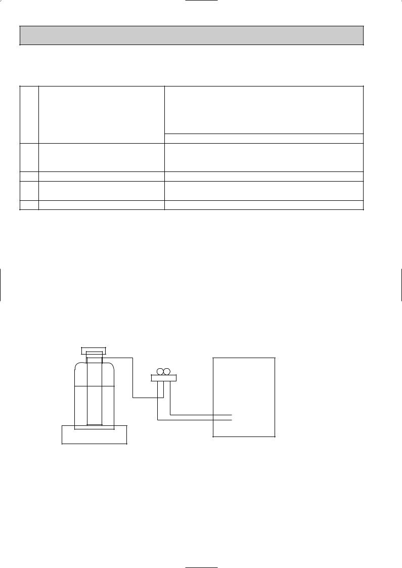
[3] Refrigerant recharging
(1) Refrigerant recharging process
1Direct charging from the cylinder.
·R407C cylinder are available on the market has a syphon pipe. ·Leave the syphon pipe cylinder standing and recharge it.
(By liquid refrigerant)
Unit
Gravimeter
(2) Recharge in refrigerant leakage case
·After recovering the all refrigerant in the unit, proceed to working. ·Do not release the refrigerant in the air.
·After completing the repair service, recharge the cycle with the specified amount of liquid refrigerant.
4
4 
 PART NAMES AND FUNCTIONS
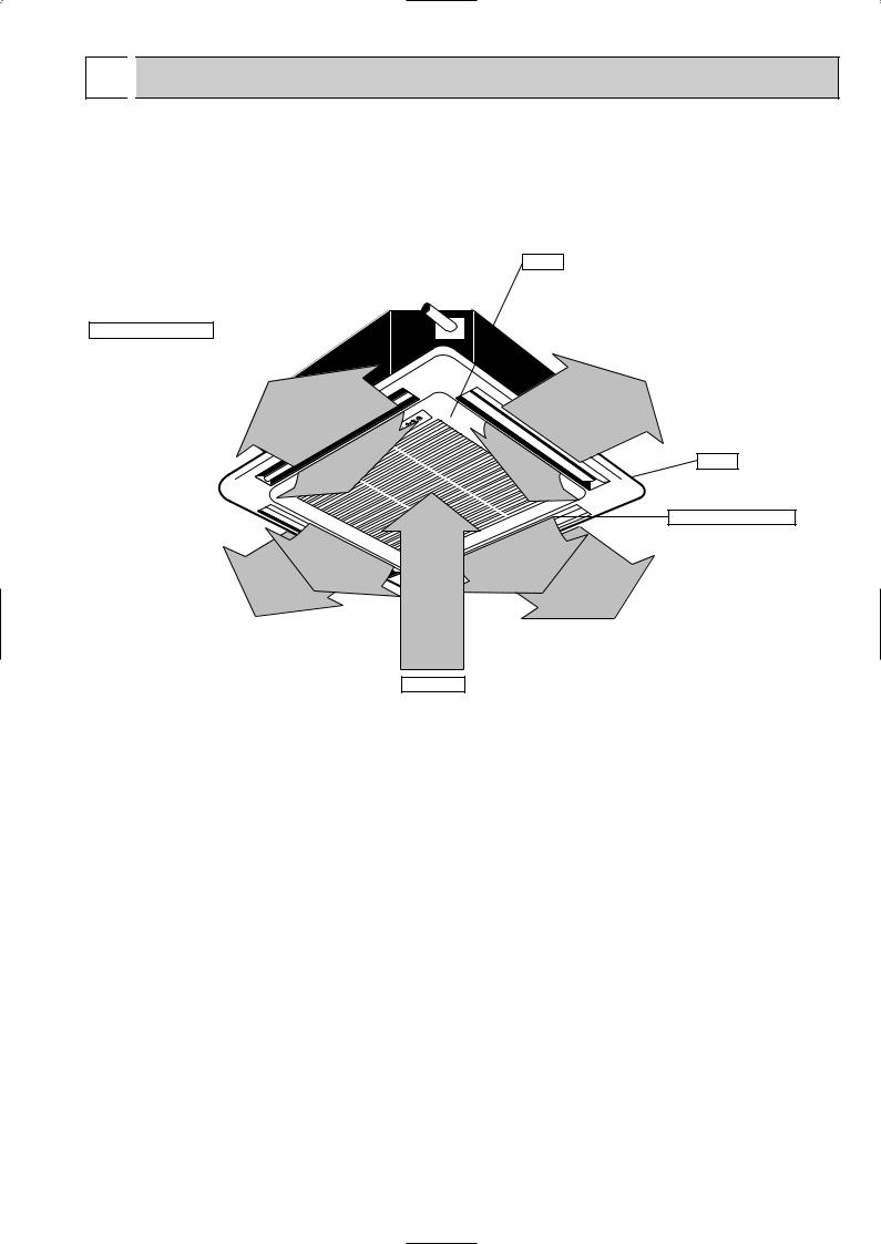
● Indoor (Main) Unit
PLA-P1.6KA.UK, PLA-P2KA.UK, PLA-P2.5KA.UK PLA-P1.6KA1.UK, PLA-P2KA1.UK, PLA-P2.5KA1.UK
Filters
Remove dust and pollutants from inhaled air
Horizontal Air Outlet
Sets airflow horizontal automatically during cooling or dehumidifying.
Grille
Auto Air Swing Vane Disperses airflow up and down and adjusts the angle of airflow direction.
Air Intake
Inhales air from room.
5
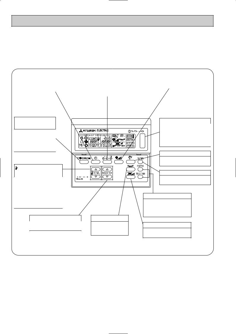
● Remote controller
● Once the controls are set, the same operation mode can be repeated by simply pressing the ON/OFF button.
PLA-P1.6KA.UK, PLA-P2KA.UK, PLA-P2.5KA.UK
● Operation buttons [ PAR-S27A-E ]
|
|
TIME SETTING button |
|
|
|
|
|
This sets of switches the |
|
AIR SPEED button |
|
TIMER button |
|
|
|||
|
|
|
|||
|
|
current time. start time and |
|
This sets the fan speed. |
|
This switches between |
|||||
|
stop time. |
|
|
||
continuous operation and |
|
|
|
||
|
|
|
|
||
the timer operation. |
|
|
|
|
|
|
|
|
|
|
OPERATION SWITCH |
|
ON/OFF button |
|
button |
|
|
This switches between the |
Press this button to |
|
operation and stop modes |
|
switch the cooler elec- |
|
each time it is pressed. The |
|
tronic dry (dehumidify) |
|
lamp on this button lights dur- |
|
automatic and heater |
|
ing operation. |
|
modes. |
|
|
AIR DIRECTION button |
|
|
|
|
|
|
|
This adjusts the vertical angle |
TEMP. ADJUSTMENT |
|
of the ventilation. |
|
|
FILTER button |
||
button |
|
|
|
This sets the room tempera- |
|
This resets the filter cleaning |
|
|
indication display. |
||
ture The temperature setting |
|
||
|
|
||
can be performed in 1°C |
|
|
|
units |
|
|
CHECK-TEST RUN button |
Setting range |
|
||
Cooler |
19°C to 30°C |
|
Only press this button to per- |
Heater |
17°C to 28°C |
|
form an inspection check or |
|
|
|
test operation Do not use it |
TIMER ADJUSTMENT button |
LOUVER button |
for normal operation. |
|
|
|||
This adjust the current time, start |
This switches the hori- |
VENTILATION button |
|
time and stop time. |
zontal fan motion ON |
This sets the ventilation fan |
|
|
|
and OFF. |
|
|
|
speed. |
|
|
|
(This button does not |
|
|
|
|
|
|
|
operate in this model) |
|
6
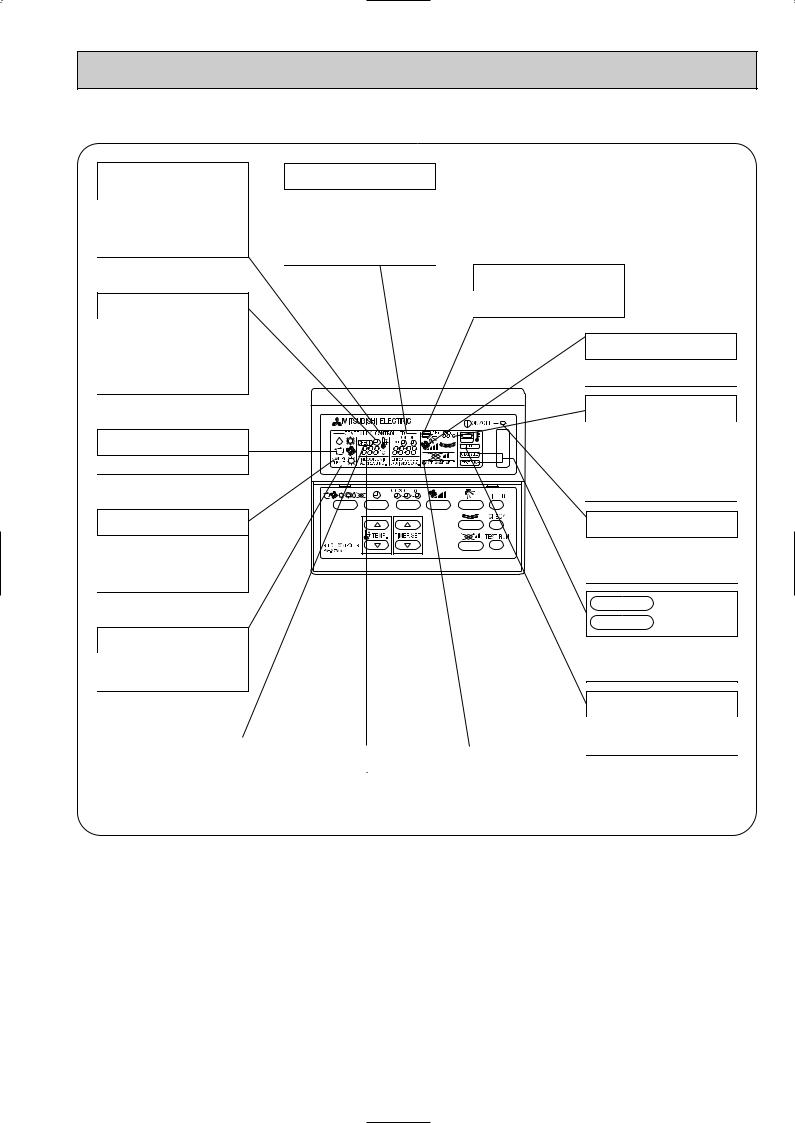
● Display
CENTRALLY CONTROLLED display
This indicates when the unit is controlled by optional features such as central control type remote controller.
TIMER display
This indicates when the continuous operation and time operation modes are set.
It also display the time for the timer operation at the same time as when it is set.
OPERATION MODE display
This indicates the operation mode.
STANDBY display
This indicates when the standby mode is set from the time the sleep operation starts until the heating air is discharged.
DEFROST display
This indicates when the defrost operation is performed.
CLOCK display
The current time , start time and stop time can be displayed in ten second intervals by pressing the time switch button. The start time or stop time is always displayed during the timer operation.
In this display example on the bottom left, a condition where all display lamps light is shown for explanation purposes although this differs from actual operation.
AIR DIRECTION display
This displays the air direction.
FAN SPEED display
The selected fan speed is displayed.
ROOM TEMPERATURE display
The temperature of the suction air is displayed during operation. The display range is 8° to 39°C. The display flashes 8°C when the actual temperature is less than 8° and flashes 39°C when the actual temperature is greater than 39°C.
Operation lamp
This lamp lights during operation, goes off when the unit stops and flashes when a malfunction occurs.
CHECK MODE
display
TEST RUN
This display lights in the check mode or when a test operation is performed.
CHECK display |
|
|
|
|
This indicates when a malfunction |
|
SET TEMPERATURE display |
|
POWER display |
|
|
|
|
|
has occurred in the unit which should |
|
This displays the selected setting |
|
This lamp lights when electricity is |
be checked. |
|
|
||
|
temperature. |
|
supplied to the unit. |
|
|
|
|
||
|
|
|
|
|
Caution
FILTER display
This lamp lights when the filter need to be cleaned.
●Only the Power display lights when the unit is stopped and power supplied to the unit.
●When power is turned ON for the first time the (CENTRAL CTRL) display appears to go off momentarily but this is not a malfunction.
●When the central control remote control unit, which is sold separately, is used the ON-OFF button, operation switch button and  TEMP. adjustment button do not operate.
●“NOT AVAILABLE” is displayed when the Air speed button are pressed.This indicates that this room unit is not equipped with the fan direction adjustment function and the louver function.
●When power is turned ON for the first time, it is normal that “H0” is displayed on the room temperature indication (For max. 2minutes). Please wait until this “H0” indication disappear then start the operation.
7
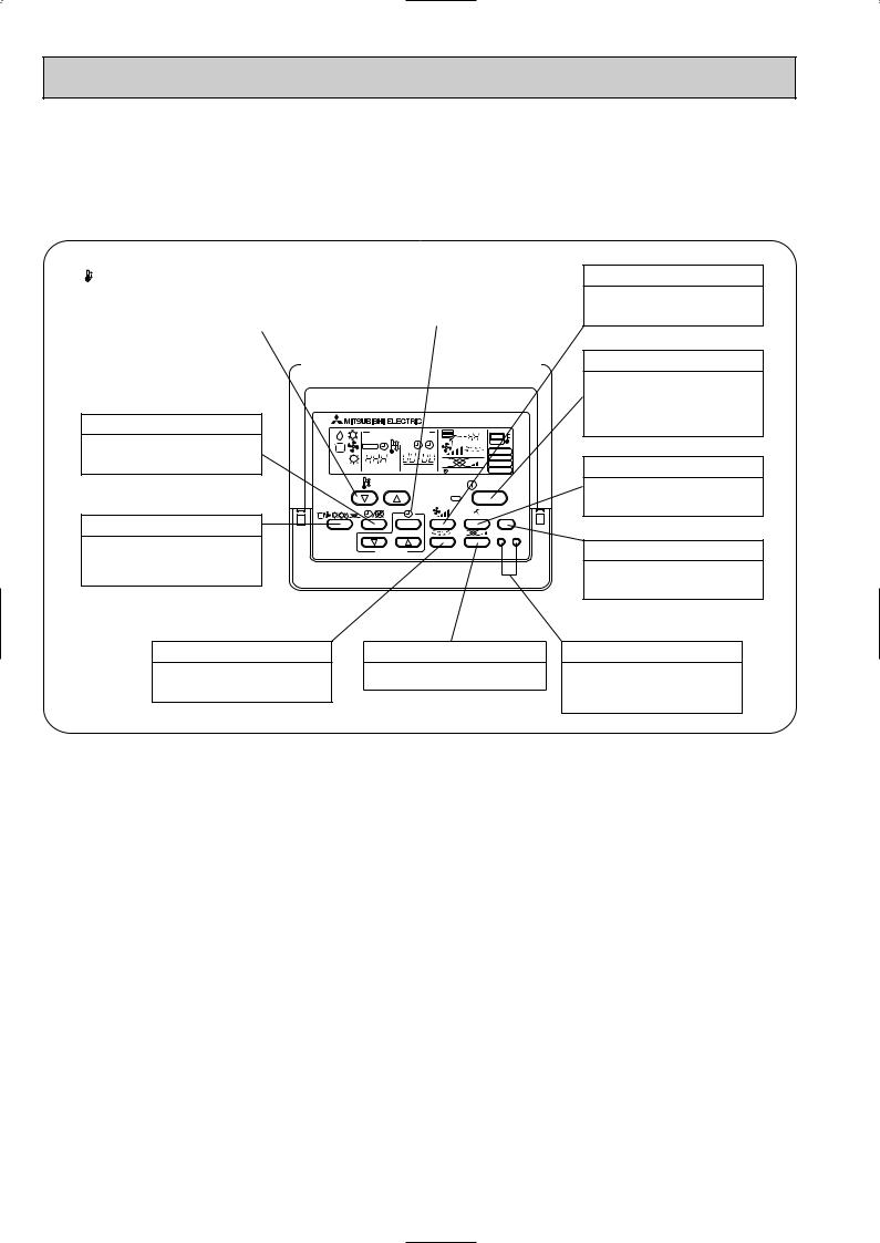
PLA-P1.6KA1.UK, PLA-P2KA1.UK, PLA-P2.5KA1.UK
● Operation buttons [PAR-20MAA-E ]
|
|
TEMP. ADJUSTMENT button |
|
|
TIME SETTING button |
|
|
|
|
||||
|
|
|
|
|
|
|
|
This sets the room temperature. The |
|
|
This sets the current time, start time |
|
|
|
temperature setting can be performed |
|
|
and stop time. |
|
|
|
in 1: units |
|
|
|
|
|
|
|
|
|
|
||
|
|
Setting range |
|
|
|
|
|
|
Cooler 19: to 30: |
|
|
|
|
|
|
Heater 17: to 28: |
|
|
|
|
|
|
|
|
|
|
|
TIMER button
This switches between continuous operation and the timer operation.
OPERATION SWITCH button
Press this button to switch the cooler, electronic dry (dehumidify), automatic and heater modes.
|
CENTRALLY CONTROLLED |
1Hr. |
|
|
|
|
ON OFF |
|
˚C |
|
CHECK |
CLOCK |
|
|
|
|
|
|
|
|
|
|
|
FILTER |
|
˚C |
|
|
CHECK MODE |
STAND BY |
ERROR CODE |
|
TEST RUN |
|
|
NOT AVAILABLE |
FUNCTION |
||
DEFROST |
|
|||
|
|
|||
|
TEMP. |
|
|
ON/OFF |
FILTER
CHECK TEST
PAR-20MAA |
TIMER SET |
AIR SPEED button
This sets the ventilation fan speed.
ON/OFF button
This switches between the operation and stop modes each time it is pressed. The lamp on this button lights during operation.
AIR DIRECTION button
This adjusts the vertical angle of the ventilation.
FILTER button
This resets the filter service indication display
LOUVER button
This switch the horizontal fan motion ON and OFF.
(Not available for this model.)
VENTILATION button
This sets the ventilation fan speed.
CHECK-TEST RUN button
Only press this button to perform an inspection check or test operation. Do not use it for normal operation.
8
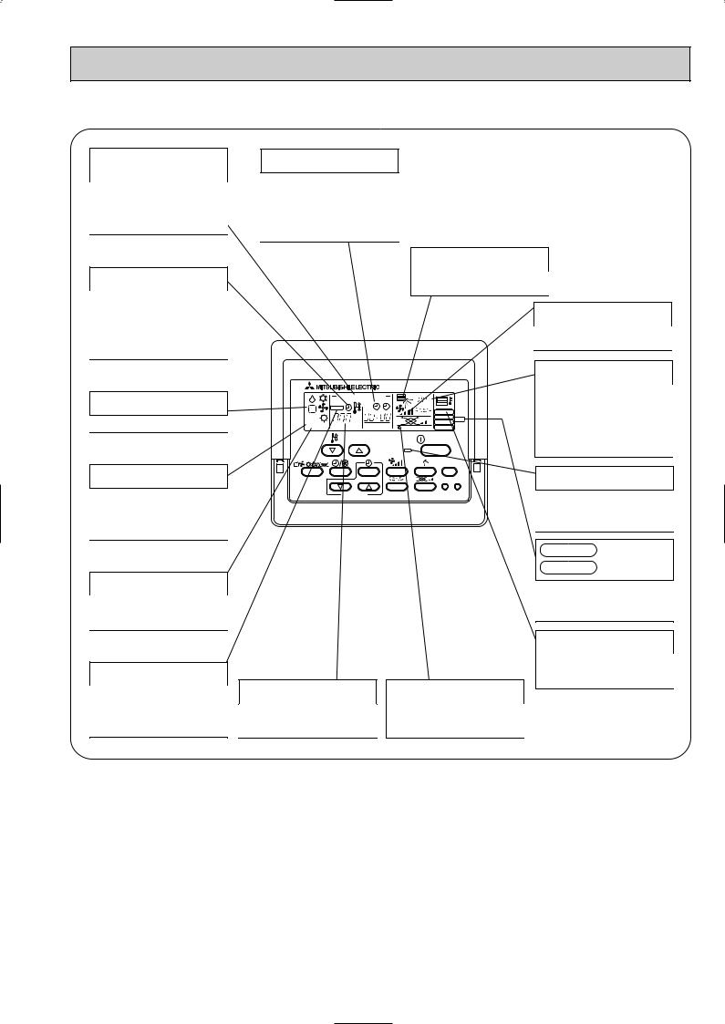
● Display
CENTRALLY CONTROLLED display
This indicates when the unit is controlled by optional features such as central control type remote controller.
CLOCK display
The current time , start time and stop time can be displayed in ten second intervals by pressing the time switch button. The start time or stop time is always displayed during the timer operation.
In this display example on the bottom left, a condition where all display lamps light is shown for explanation purposes although this differs from actual operation.
TIMER display
This indicates when the continuous operation and time operation modes are set.
It also display the time for the timer operation at the same time as when it is set.
OPERATION MODE display
This indicates the operation mode.
STANDBY display
The [STANDBY] symbol is only displayed from the time the heating operation starts unit the heated air begins to blow.
DEFROST display
This indicates when the defrost operation is performed.
AIR DIRECTION display
This displays the air direction.
|
CENTRALLY CONTROLLED |
1Hr. |
|
|
|
|
ON OFF |
|
˚C |
|
CHECK |
CLOCK |
|
|
|
|
|
|
|
|
|
|
|
FILTER |
|
˚C |
|
|
CHECK MODE |
STAND BY |
ERROR CODE |
|
TEST RUN |
|
|
NOT AVAILABLE |
FUNCTION |
||
DEFROST |
|
|||
|
TEMP. |
|
|
ON/OFF |
FILTER
CHECK TEST
PAR-20MAA |
TIMER SET |
AIR SPEED display
The selected fan speed is displayed.
ROOM TEMPERATURE display
The temperature of the suction air is displayed during operation. The display range is 8°C to 39°C. The display flashes 8°C when the actual temperature is less than 8°C and flashes 39°C when the actual temperature is greater than 39°C.
Operation lamp
This lamp lights during operation, goes off when the unit stops and flashes when a malfunction occurs.
CHECK MODE
display
TEST RUN
This display lights in the check mode or when a test operation is performed.
CHECK display
This indicates when a malfunction has occurred in the unit which should be checked.
SET TEMPERATURE display
This displays the selected setting temperature.
POWER display
This lamp lights when electricity is supplied to the unit.
FILTER display
This lamp lights when the filter need to be cleaned.
Caution
●Only the Power display lights when the unit is stopped and power supplied to the unit.
●When the central control remote control unit, which is sold separately, is used the ON-OFF button, operation switch button and  TEMP. adjustment button do not operate.
●“NOT AVAILABLE” is displayed when the Air speed button are pressed.This indicates that this room unit is not equipped with the fan direction adjustment function and the louver function.
●When power is turned ON for the first time, it is normal that “H0” is displayed on the room temperature indication (For max. 2minutes). Please wait until this “H0” indication disappear then start the operation.
9
|
5 |
|
|
SPECIFICATIONS |
|
|
|
|||
|
|
|
|
|
|
|
|
|
|
|
|
1. Heat pump type |
|
|
|
|
|
||||
|
|
|
|
|
|
|
|
|
|
|
|
Item |
|
|
Service Ref. |
|
PLA-P1.6KA.UK |
|
|||
|
|
|
|
|
|
|||||
|
|
|
|
|
|
|
||||
|
Function |
|
|
|
Cooling |
Heating |
|
|||
|
Capacity |
|
|
Btu/h |
15,000 |
17,100 |
|
|||
|
|
|
W |
4,400 |
5,000 |
|
||||
|
|
|
|
|
|
|
|
|||
|
Total input |
|
|
kW |
1.86 |
1.93 |
|
|||
|
|
Service Ref. |
|
|
|
PLA-P1.6KA.UK |
|
|||
|
|
Power supply(phase, cycle, voltage) |
|
Single Phase, 50Hz, 220-230-240V |
|
|||||
|
|
|
|
|
Input |
|
kW |
0.15 |
0.10 |
|
|
|
|
|
|
Running current |
|
A |
0.64 |
0.45 |
|
|
|
|
|
|
Starting current |
|
A |
0.70 |
0.50 |
|
|
|
External finish |
|
|
Galvanized sheets with gray heat insulation |
|
||||
|
UNIT |
Heat exchanger |
|
|
|
Plate fin coil |
|
|||
|
Fan |
Fan(drive) x No. |
|
|
|
Turbo fan (direct) x 1 |
|
|||
|
|
|
|
|
|
|||||
|
INDOOR |
|
|
|
Fan motor output |
|
kW |
|
0.030 |
|
|
|
|
|
Airflow(Lo-Mi2-Mi1-Hi) |
K/min(CFM) |
13-14-15-16(459-494-530-565) |
|
|||
|
|
|
|
|
|
|||||
|
|
|
|
|
External static pressure |
Pa(mmAq) |
|
0(direct blow) |
|
|
|
|
Operation control & Thermostat |
|
|
Remote controller & built-in |
|
||||
|
|
Noise level(Lo-Mi2-Mi1-Hi) |
|
dB |
|
32-34-35.5-37 |
|
|||
|
|
Unit drain pipe I.D. |
|
mm(in.) |
|
32(1-1/4) |
|
|||
|
|
Dimensions |
W |
mm(in.) |
UNIT : 660(26) PANEL : 760(30) |
|
||||
|
|
|
|
|
|
D |
mm(in.) |
UNIT : 660(26) PANEL : 760(30) |
|
|
|
|
|
|
|
|
H |
mm(in.) |
UNIT : 253(10) PANEL : 30(1-3/16) |
|
|
|
|
Weight |
|
|
kg(lbs) |
UNIT : 19(42) PANEL : 3.7(8) |
|
|||
|
|
Service Ref. |
|
|
PUH-P1.6VGA / PUH-P1.6YGA |
|
||||
|
|
Power supply (phase, cycle, voltage) |
|
Single Phase, 50Hz, 220-230-240V / 3 phases, 50Hz, 380-400-415V(4wires) |
|
|||||
|
|
|
|
|
Running current |
|
A |
7.66 / 2.67 |
8.19 / 2.86 |
|
|
|
|
|
|
Starting current |
|
A |
|
36 / 20 |
|
|
|
External finish |
|
|
|
Munsell 5Y 8/1 |
|
|||
|
|
Refrigerant control |
|
|
|
Linear Expansion Valve |
|
|||
|
|
Compressor |
|
|
|
Hermetic |
|
|||
|
UNIT |
|
|
|
Model |
|
|
|
RE277VHSM / RE277YFKM |
|
|
|
|
|
Motor output |
|
kW |
|
1.3 |
|
|
|
|
|
|
|
|
|
|
|||
|
OUTDOOR |
|
|
|
Starter type |
|
|
|
Line start |
|
|
|
|
|
Protection devices |
|
|
Inner thermostat, HP switch, Discharge thermo./ Thermal relay, Discharge thermo, HP switch, Anti-phase protector. |
|
||
|
|
|
|
|
|
|
|
|||
|
|
|
|
|
Crankcase heater |
|
W |
|
30 |
|
|
|
Heat exchanger |
|
|
|
Plate fin coil |
|
|||
|
|
Fan |
Fan(drive) x No. |
|
|
|
Propeller (direct) x 1 |
|
||
|
|
|
|
|
Fan motor output |
|
kW |
|
0.070 |
|
|
|
|
|
|
Airflow |
|
K/min(CFM) |
|
45(1,590) |
|
|
|
Defrost method |
Cooling |
|
|
Reverse cycle |
|
|||
|
|
Noise level |
dB |
|
46 |
|
||||
|
|
|
|
|
|
Heating |
dB |
|
48 |
|
|
|
Dimensions |
W |
mm(in.) |
|
900(35-7/16) |
|
|||
|
|
|
|
|
|
D |
mm(in.) |
|
330+20(13+3/4) |
|
|
|
|
|
|
|
H |
mm(in.) |
|
650 (25-5/8) |
|
|
|
Weight |
|
|
kg(lbs) |
|
55(121) |
|
||
|
PIPING |
Refrigerant |
|
|
|
R407C |
|
|||
|
|
|
|
Charge |
|
kg(lbs) |
|
2.6(5.7) |
|
|
|
|
|
|
Oil (Model) |
Liquid |
L |
|
0.57 (Ester)MEL56 |
|
|
|
REFRIGERANT |
Pipe size O.D. |
mm(in.) |
|
9.52 (3/8) |
|
||||
|
outdoor unit |
Piping length |
|
Max. 40m |
|
|||||
|
|
|
|
|
|
Gas |
mm(in.) |
|
15.88 (5/8) |
|
|
|
Connection method |
Indoor side |
|
Flared |
|
||||
|
|
|
|
|
|
Outdoor side |
|
Flared |
|
|
|
|
Between the indoor & |
Height difference |
|
Max. 40m |
|
||||
|
|
|
|
|
|
|
|
|
|
|
Notes1. Rating Conditions (ISO T1) |
|
|
|
|
|
|
||||
Cooling : Indoor |
: D.B. 27˚C(80˚F) |
W.B. 19˚C (66˚F) Outdoor |
: D.B. 35˚C(95˚F) |
W.B. 24˚C (75˚F) |
||||||
Heating : Indoor |
: D.B. 20˚C(68˚F) |
|
Outdoor |
: D.B. 7˚C(45˚F) |
W.B. 6˚C (43˚F) |
|||||
Refrigerant piping length (one way) : 5m (16ft) |
|
|
|
|
|
|||||
2. Guaranteed operating range |
|
|
|
|
|
|
||||
|
|
|
|
Indoor |
Outdoor |
|
|
|
||
|
Cooling |
Upper limit |
D.B. 35˚C |
W.B. 22.5˚C |
D.B. 46˚C |
|
|
|
|
|
|
Lower limit |
D.B. 19˚C |
W.B. 15˚C |
D.B. -5˚C |
|
|
|
|
||
|
|
|
|
|
|
|||||
|
Heating |
Upper limit |
D.B. 28˚C |
|
D.B. 24˚C |
W.B. 18˚C |
|
|
||
|
Lower limit |
D.B. 17˚C |
|
D.B. -11˚C |
W.B. -12˚C |
|
|
|||
3. Above data based on indicated voltage |
|
|
Indoor Unit |
Single phase 240V |
50Hz |
Outdoor Unit |
Single phase 240V |
50Hz / 3 phases 415V 50Hz |
10
|
|
|
|
|
|
|
|
|
|
|
|
|
|
|
|
|
|
|
|
|
Item |
|
|
Service Ref. |
|
PLA-P2KA.UK |
|||
|
|
|
|
|
|||||
|
|
|
|
|
|
|
|
||
|
Function |
|
|
|
Cooling |
|
Heating |
||
|
Capacity |
|
|
Btu/h |
18,400 |
|
21,300 |
|
|
|
|
|
W |
5,400 |
|
6,250 |
|
||
|
|
|
|
|
|
|
|||
|
Total input |
|
|
kW |
2.62 |
|
2.67 |
|
|
|
|
Service Ref. |
|
|
|
PLA-P2KA.UK |
|||
|
|
Power supply(phase, cycle, voltage) |
|
Single Phase, 50Hz, 220-230-240V |
|||||
|
|
|
Input |
|
kW |
0.14 |
|
0.10 |
|
|
|
|
Running current |
|
A |
0.65 |
|
0.45 |
|
|
|
|
Starting current |
|
A |
0.72 |
|
0.50 |
|
|
|
External finish |
|
|
Galvanized sheets with gray heat insulation |
||||
|
UNIT |
Heat exchanger |
|
|
|
Plate fin coil |
|||
|
Fan |
Fan(drive) x No. |
|
|
|
Turbo fan (direct) x 1 |
|||
|
|
Fan motor output |
|
kW |
|
0.030 |
|
||
|
INDOOR |
|
|
|
|
||||
|
|
Airflow(Lo-Mi2-Mi1-Hi) |
K/min(CFM) |
13-14-15-16(459-494-530-565) |
|
||||
|
|
External static pressure |
Pa(mmAq) |
|
0(direct blow) |
||||
|
Operation control & Thermostat |
|
|
Remote controller & built-in |
|||||
|
|
|
|
||||||
|
|
Noise level(Lo-Mi2-Mi1-Hi) |
|
dB |
|
32-34-35.5-37 |
|
||
|
|
Unit drain pipe I.D. |
|
mm(in.) |
|
32(1-1/4) |
|
||
|
|
Dimensions |
W |
mm(in.) |
UNIT : 660(26) PANEL : 760(30) |
||||
|
|
|
|
D |
mm(in.) |
UNIT : 660(26) PANEL : 760(30) |
|||
|
|
Weight |
|
H |
mm(in.) |
UNIT : 253(10) |
PANEL : 30(1-3/16) |
||
|
|
|
|
kg(lbs) |
UNIT : 19(42) |
PANEL : 3.7(8) |
|||
|
|
Service Ref. |
|
|
|
PUH-P2VGA / PUH-P2YGA |
|||
|
|
Power supply (phase, cycle, voltage) |
|
Single Phase, 50Hz, 220-230-240V / 3 phases, 50Hz, 380-400-415V(4wires) |
|||||
|
|
|
Running current |
|
A |
11.11 / 3.88 |
|
11.51 / 4.02 |
|
|
|
|
Starting current |
|
A |
|
74 / 30 |
|
|
|
|
External finish |
|
|
|
Munsell 5Y 8/1 |
|||
|
|
Refrigerant control |
|
|
|
Linear Expansion Valve |
|||
|
|
Compressor |
|
|
|
Hermetic |
|||
|
UNIT |
|
Model |
|
|
|
NE38VMJM / NE38YEJM |
||
|
|
Motor output |
|
kW |
|
1.7 |
|
||
|
|
Starter type |
|
|
|
Line start |
|||
|
OUTDOOR |
|
|
|
|
||||
|
|
Protection devices |
|
|
Inner thermostat, HP switch, Discharge thermo./ Thermal relay, Discharge thermo, HP switch, Anti-phase protector. |
||||
|
|
Crankcase heater |
|
W |
|
38 |
|
|
|
|
Heat exchanger |
|
|
|
Plate fin coil |
||||
|
Fan |
Fan(drive) x No. |
|
|
|
Propeller (direct) x 1 |
|||
|
|
|
Fan motor output |
|
kW |
|
0.070 |
|
|
|
|
|
Airflow |
|
K/min(CFM) |
|
55(1,940) |
|
|
|
|
Defrost method |
|
|
|
Reverse cycle |
|||
|
|
Noise level |
Cooling |
dB |
|
48 |
|
|
|
|
|
|
|
Heating |
dB |
|
49 |
|
|
|
|
Dimensions |
W |
mm(in.) |
|
900(35-7/16) |
|
||
|
|
|
|
D |
mm(in.) |
|
330+20(13+3/4) |
|
|
|
|
|
|
H |
mm(in.) |
|
855 (33-5/8) |
|
|
|
|
Weight |
|
|
kg(lbs) |
|
71(157) |
|
|
|
PIPING |
Refrigerant |
|
|
|
R407C |
|||
|
|
Charge |
|
kg(lbs) |
|
3.1(6.8) |
|
||
|
|
Oil (Model) |
|
L |
|
1.2 (Ester)MEL56 |
|||
|
REFRIGERANT |
Pipe size O.D. |
Liquid |
mm(in.) |
|
9.52 (3/8) |
|
||
|
|
|
Gas |
mm(in.) |
|
15.88 (5/8) |
|
||
|
Connection method |
Indoor side |
|
Flared |
|||||
|
|
|
Outdoor side |
|
Flared |
||||
|
Between the indoor & |
Height difference |
|
Max. 40m |
|||||
|
outdoor unit |
Piping length |
|
Max. 40m |
|||||
Notes1. Rating Conditions (ISO T1) |
|
|
|
|
|
|
||||
Cooling : Indoor |
: D.B. 27˚C(80˚F) |
W.B. 19˚C (66˚F) Outdoor |
: D.B. 35˚C(95˚F) |
W.B. 24˚C (75˚F) |
||||||
Heating : Indoor |
: D.B. 20˚C(68˚F) |
|
Outdoor |
: D.B. 7˚C(45˚F) |
W.B. 6˚C (43˚F) |
|||||
Refrigerant piping length (one way) : 5m (16ft) |
|
|
|
|
|
|||||
2. Guaranteed operating range |
|
|
|
|
|
|
||||
|
|
|
|
Indoor |
Outdoor |
|
|
|
||
|
Cooling |
Upper limit |
D.B. 35˚C |
W.B. 22.5˚C |
D.B. 46˚C |
|
|
|
|
|
|
Lower limit |
D.B. 19˚C |
W.B. 15˚C |
D.B. -5˚C |
|
|
|
|
||
|
|
|
|
|
|
|||||
|
Heating |
Upper limit |
D.B. 28˚C |
|
D.B. 24˚C |
W.B. 18˚C |
|
|
||
|
Lower limit |
D.B. 17˚C |
|
D.B. -11˚C |
W.B. -12˚C |
|
|
|||
3. Above data based on indicated voltage |
|
|
Indoor Unit |
Single phase 240V |
50Hz |
Outdoor Unit |
Single phase 240V |
50Hz / 3 phases 415V 50Hz |
11

|
|
|
|
|
|
|
|
|
|
|
|
|
|
|
|
|
|
|
|
|
Item |
|
|
Service Ref. |
|
PLA-P2.5KA.UK |
|
||
|
|
|
|
|
|
||||
|
|
|
|
|
|
|
|
||
|
|
|
|
|
|
|
|
|
|
|
Function |
|
|
|
Cooling |
|
Heating |
|
|
|
Capacity |
|
|
Btu/h |
21,500 |
|
25,200 |
|
|
|
|
|
W |
6,300 |
|
7,400 |
|
||
|
|
|
|
|
|
|
|||
|
Total input |
|
|
kW |
2.77 |
|
2.68 |
|
|
|
|
Service Ref. |
|
|
|
PLA-P2.5KA.UK |
|
||
|
|
Power supply(phase, cycle, voltage) |
|
Single Phase, 50Hz, 220-230-240V |
|
||||
|
|
|
Input |
|
kW |
0.14 |
|
0.10 |
|
|
|
|
Running current |
|
A |
0.61 |
|
0.45 |
|
|
|
|
Starting current |
|
A |
0.67 |
|
0.50 |
|
|
|
External finish |
|
|
Galvanized sheets with gray heat insulation |
|
|||
|
UNIT |
Heat exchanger |
|
|
|
Plate fin coil |
|
||
|
Fan |
Fan(drive) x No. |
|
|
|
Turbo fan (direct) x 1 |
|
||
|
|
|
|
|
|
||||
|
INDOOR |
|
Fan motor output |
|
kW |
|
0.030 |
|
|
|
|
Airflow(Lo-Mi2-Mi1-Hi) |
K/min(CFM) |
14-15-16-17 (494-530-565-600) |
|
||||
|
|
|
|
||||||
|
|
|
External static pressure |
Pa(mmAq) |
|
0(direct blow) |
|
||
|
|
Operation control & Thermostat |
|
|
Remote controller & built-in |
|
|||
|
|
Noise level(Lo-Mi2-Mi1-Hi) |
|
dB |
|
35-36.5-38-39.5 |
|
||
|
|
Unit drain pipe I.D. |
|
mm(in.) |
|
32(1-1/4) |
|
||
|
|
Dimensions |
W |
mm(in.) |
UNIT : 660(26) PANEL : 760(30) |
|
|||
|
|
|
|
D |
mm(in.) |
UNIT : 660(26) PANEL : 760(30) |
|
||
|
|
Weight |
|
H |
mm(in.) |
UNIT : 253(10) PANEL : 30(1-3/16) |
|
||
|
|
|
|
kg(lbs) |
UNIT : 20(44) PANEL : 3.7(8) |
|
|||
|
|
Service Ref. |
|
|
PUH-P2.5VGA1 / PUH-P2.5YGA1 |
|
|||
|
|
Power supply (phase, cycle, voltage) |
|
Single Phase, 50Hz, 220-230-240V / 3 phases, 50Hz, 380-400-415V(4wires) |
|
||||
|
|
|
Running current |
|
A |
11.78 / 4.11 |
11.55 / 4.03 |
|
|
|
|
|
Starting current |
|
A |
|
77 / 32 |
|
|
|
|
External finish |
|
|
|
Munsell 5Y 8/1 |
|
||
|
|
Refrigerant control |
|
|
|
Linear Expansion Valve |
|
||
|
|
Compressor |
|
|
|
Hermetic |
|
||
|
UNIT |
|
Model |
|
|
|
NE41VMJM / NE41YEJM |
|
|
|
|
Motor output |
|
kW |
|
1.9 |
|
||
|
|
|
|
|
|
||||
|
OUTDOOR |
|
Starter type |
|
|
|
Line start |
|
|
|
|
Protection devices |
|
|
Internal thermostat, HP switch, Discharge thermo./ Thermal relay, Discharge thermo, HP switch, Anti-phase protector. |
|
|||
|
|
|
|
|
|
||||
|
|
|
Crankcase heater |
|
W |
|
38 |
|
|
|
|
Heat exchanger |
|
|
|
Plate fin coil |
|
||
|
|
Fan |
Fan(drive) x No. |
|
|
|
Propeller (direct) x 1 |
|
|
|
|
|
Fan motor output |
|
kW |
|
0.070 |
|
|
|
|
|
Airflow |
|
K/min(CFM) |
|
50(1,770) |
|
|
|
|
Defrost method |
|
|
|
Reverse cycle |
|
||
|
|
Noise level |
Cooling |
dB |
|
48 |
|
||
|
|
|
|
Heating |
dB |
|
50 |
|
|
|
|
Dimensions |
W |
mm(in.) |
|
900(35-7/16) |
|
||
|
|
|
|
D |
mm(in.) |
|
330+20(13+3/4) |
|
|
|
|
|
|
H |
mm(in.) |
|
855 (33-5/8) |
|
|
|
|
Weight |
|
|
kg(lbs) |
|
82(181) |
|
|
|
PIPING |
Refrigerant |
|
|
|
R407C |
|
||
|
|
Charge |
|
kg(lbs) |
|
3.3(7.3) |
|
||
|
|
Oil (Model) |
Liquid |
L |
|
1.2 (Ester)MEL56 |
|
||
|
REFRIGERANT |
Pipe size O.D. |
mm(in.) |
|
9.52 (3/8) |
|
|||
|
outdoor unit |
Piping length |
|
Max. 50m |
|
||||
|
|
|
|
Gas |
mm(in.) |
|
15.88 (5/8) |
|
|
|
|
Connection method |
Indoor side |
|
Flared |
|
|||
|
|
|
|
Outdoor side |
|
Flared |
|
||
|
|
Between the indoor & |
Height difference |
|
Max. 50m |
|
|||
|
|
|
|
|
|
|
|
|
|
Notes1. Rating Conditions (ISO T1) |
|
|
|
|
|
|
||||
Cooling : Indoor |
: D.B. 27˚C(80˚F) |
W.B. 19˚C (66˚F) Outdoor |
: D.B. 35˚C(95˚F) |
W.B. 24˚C (75˚F) |
||||||
Heating : Indoor |
: D.B. 20˚C(68˚F) |
|
Outdoor |
: D.B. 7˚C(45˚F) |
W.B. 6˚C (43˚F) |
|||||
Refrigerant piping length (one way) : 5m (16ft) |
|
|
|
|
|
|||||
2. Guaranteed operating range |
|
|
|
|
|
|
||||
|
|
|
|
|
|
|
|
|
||
|
|
|
|
Indoor |
Outdoor |
|
|
|
||
|
Cooling |
Upper limit |
D.B. 35˚C |
W.B. 22.5˚C |
D.B. 46˚C |
|
|
|
|
|
Lower limit |
D.B. 19˚C |
W.B. 15˚C |
D.B. -5˚C |
|
|
|
|
|||
|
|
|
|
|
|
|||||
|
Heating |
Upper limit |
D.B. 28˚C |
|
D.B. 24˚C |
W.B. 18˚C |
|
|
||
|
Lower limit |
D.B. 17˚C |
|
D.B. -11˚C |
W.B. -12˚C |
|
|
|||
3. Above data based on indicated voltage |
|
|
Indoor Unit |
Single phase 240V |
50Hz |
Outdoor Unit |
Single phase 240V |
50Hz / 3 phases 415V 50Hz |
12

|
|
|
|
|
|
|
|
|
|
|
|
|
|
|
|
|
|
|
|
Item |
|
|
|
|
Service Ref. |
|
PLA-P1.6KA.UK / PLA-P1.6KA1.UK |
||
|
|
|
|
|
|
|
|
||
Function |
|
|
|
|
|
|
Cooling |
Heating |
|
Capacity |
|
|
|
|
Btu/h |
|
15,000 |
17,100 |
|
|
|
|
|
W |
|
4,400 |
5,000 |
||
Total input |
|
|
|
|
|
||||
|
|
|
|
kW |
|
1.82 |
1.89 |
||
|
Service Ref. |
|
|
|
|
|
PLA-P1.6KA.UK / PLA-P1.6KA1.UK |
||
|
Power supply(phase, cycle,voltage) |
|
|
Single phase, 50Hz, 220-230-240V |
|||||
|
|
Input |
|
|
|
kW |
|
0.15 |
0.10 |
|
|
Running current |
|
A |
|
0.64 |
0.45 |
||
|
|
Starting current |
|
A |
|
0.70 |
0.50 |
||
UNIT |
External finish |
|
|
|
|
|
Galvanized sheets with gray heat insulation |
||
Heat exchanger |
|
|
|
|
|
|
Plate fin coil |
||
Fan |
Fan(drive) x No. |
|
kW |
|
Turbo fan (direct) x 1 |
||||
INDOOR |
|
Fan motor output |
|
|
|
0.030 |
|||
|
Airflow(Lo-Mi2-Mi1-Hi) |
K/min(CFM) |
13-14-15-16 (459-494-530-565) |
||||||
|
|
||||||||
|
|
External static pressure |
Pa(mmAq) |
|
|
0(direct blow) |
|||
|
Operation control & Thermostat |
|
|
Remote controller & built-in |
|||||
|
Noise level(Lo-Mi2-Mi1-Hi) |
|
dB |
|
|
32-34-35.5-37 |
|||
|
Unit drain pipe I.D. |
|
|
mm(in.) |
|
|
32(1-1/4) |
||
|
Dimensions |
|
|
W |
mm(in.) |
|
UNIT : 660(26) PANEL : 760(30) |
||
|
|
|
|
|
D |
mm(in.) |
|
UNIT : 660(26) PANEL : 760(30) |
|
|
Weight |
|
|
H |
mm(in.) |
|
UNIT : 253(10) PANEL : 30(1-3/16) |
||
|
|
|
|
kg(lbs) |
|
UNIT : 19(42) PANEL : 3.7(8) |
|||
|
Service Ref. |
|
|
|
|
|
PUH-P1.6VGAA.UK / PUH-P1.6YGAA.UK |
||
|
Power supply (phase, cycle, voltage) |
|
|
Single phase, 50Hz, 220-230-240V / 3phases,50Hz,380-400-415V(4wies) |
|||||
|
|
Running current |
|
A |
|
7.36 / 2.49 |
7.59 / 2.56 |
||
|
|
Starting current |
|
A |
|
|
36 / 20 |
||
|
External finish |
|
|
|
|
|
|
Munsell 5Y 7/1 |
|
|
Refrigerant control |
|
|
|
|
Linear Expansion Valve |
|||
|
Compressor |
|
|
|
|
|
|
Hermetic |
|
UNIT |
|
Model |
|
|
|
|
|
RE277VHSMT / RE277YFKM |
|
|
Motor output |
|
kW |
|
|
1.3 |
|||
|
|
|
|
|
|||||
OUTDOOR |
|
Starter type |
|
|
|
|
Line start |
||
|
Protection devices |
|
|
Internal thermostat, HP switch, Discharge thermo./ Thermal relay, HP switch, Discharge thermo. |
|||||
|
|
|
|
||||||
|
|
Crankcase heater |
|
W |
|
|
Plate fin coil |
||
|
Heat exchanger |
|
|
|
|
|
Propeller (direct) x 1 |
||
|
Fan |
Fan(drive) x No. |
|
|
|
|
0.070 |
||
|
|
Fan motor output |
|
kW |
|
|
45(1,590) |
||
|
|
Airflow |
|
|
K/min(CFM) |
|
|
30 |
|
|
Defrost method |
|
|
|
|
|
|
Reverse cycle |
|
|
Noise level |
|
|
Cooling |
dB |
|
|
47 |
|
|
|
|
|
|
Heating |
dB |
|
|
49 |
|
Dimensions |
|
|
W |
mm(in.) |
|
|
900(35-7/16) |
|
|
|
|
|
|
D |
mm(in.) |
|
|
330+20(13+3/4) |
|
|
|
|
|
H |
mm(in.) |
|
|
650(25-5/8) |
|
Weight |
|
|
|
kg(lbs) |
|
|
55(121) |
|
PIPING |
Refrigerant |
|
|
|
|
|
|
R407C |
|
|
Charge |
|
|
kg(lbs) |
|
|
2.5(5.5) |
||
|
Oil (Model) |
|
Liquid |
L |
|
0.57(Ester)MEL56 |
|||
REFRIGERANT |
Pipe size O.D. |
|
|
mm(in.) |
|
|
9.52 (3/8) |
||
outdoor unit |
|
|
Piping length |
|
|
Max. 40m |
|||
|
|
|
|
|
Gas |
mm(in.) |
|
|
15.88 (5/8) |
|
Connection method |
|
Indoor side |
|
|
Flared |
|||
|
|
|
|
|
Outdoor side |
|
|
Flared |
|
|
Between the indoor & |
|
Height difference |
|
|
Max. 40m |
|||
|
|
|
|
|
|||||
Notes1. Rating Conditions (ISO T1) |
|
|
|
|
|||||
|
Cooling : Indoor |
: D.B. 27˚C(80˚F) |
W.B. 19˚C (66˚F) |
Outdoor : D.B. 35˚C(95˚F) |
W.B. 24˚C (75˚F) |
||||
|
Heating : Indoor |
: D.B. 20˚C(68˚F) |
|
|
Outdoor : D.B. 7˚C(45˚F) |
W.B. 6˚C (43˚F) |
|||
|
Refrigerant piping length (one way) : 5m (16ft) |
|
|
|
|||||
|
2. Guaranteed operating range |
|
|
|
|
||||
|
|
|
|
|
Indoor |
|
Outdoor |
|
|
|
|
Cooling |
Upper limit |
D.B. 35˚C |
W.B. 22.5˚C |
|
D.B. 46˚C |
|
|
|
|
|
Lower limit |
D.B. 19˚C |
W.B. 15˚C |
|
D.B. -5˚C |
|
|
|
|
Heating |
Upper limit |
D.B. 28˚C |
D.B. 24˚C W.B. 18˚C |
|
|||
|
|
|
Lower limit |
D.B. 17˚C |
D.B. -11˚C W.B. -12˚C |
|
|||
|
3. Above data based on indicated voltage |
|
|
|
|||||
|
|
Indoor Unit |
Single phase 240V 50Hz |
|
|
|
|||
|
|
Outdoor Unit |
Single phase 240V 50Hz / 3phases 415V 50Hz |
|
|||||
13
Service Ref.
Item
Function
Capacity |
|
|
Btu/h |
|
|
|
W |
||
|
|
|
|
|
Total input |
|
|
kW |
|
|
Service Ref. |
|
|
|
|
Power supply(phase, cycle, voltage) |
|
||
|
|
Input |
|
kW |
|
|
Running current |
|
A |
|
|
Starting current |
|
A |
|
External finish |
|
|
|
UNIT |
Heat exchanger |
|
|
|
Fan |
Fan(drive) x No. |
|
|
|
|
|
|
||
INDOOR |
|
Fan motor output |
|
kW |
|
Airflow(Lo-Mi2-Mi1-Hi) |
K/min(CFM) |
||
|
|
|||
|
|
External static pressure |
Pa(mmAq) |
|
|
Operation control & Thermostat |
|
||
|
Noise level(Lo-Mi2-Mi1-Hi) |
|
dB |
|
|
Unit drain pipe I.D. |
|
mm(in.) |
|
|
Dimensions |
W |
mm(in.) |
|
|
|
|
D |
mm(in.) |
|
Weight |
|
H |
mm(in.) |
|
|
|
kg(lbs) |
|
|
Service Ref. |
|
|
|
|
Power supply (phase, cycle, voltage) |
|
||
|
|
Running current |
|
A |
|
|
Starting current |
|
A |
|
External finish |
|
|
|
|
Refrigerant control |
|
|
|
|
Compressor |
|
|
|
UNIT |
|
Model |
|
|
|
Motor output |
|
kW |
|
|
|
|
||
OUTDOOR |
|
Starter type |
|
|
|
Protection devices |
|
|
|
|
|
|
|
|
|
|
Crankcase heater |
|
W |
|
Heat exchanger |
|
|
|
|
Fan |
Fan(drive) x No. |
|
|
|
|
Fan motor output |
|
kW |
|
|
Airflow |
|
K/min(CFM) |
|
Defrost method |
|
|
|
|
Noise level |
Cooling |
dB |
|
|
|
|
Heating |
dB |
|
Dimensions |
W |
mm(in.) |
|
|
|
|
D |
mm(in.) |
|
|
|
H |
mm(in.) |
|
Weight |
|
|
kg(lbs) |
PIPING |
Refrigerant |
|
L |
|
|
Oil (Model) |
|
||
|
|
Charge |
|
kg(lbs) |
REFRIGERANT |
Pipe size O.D. |
Liquid |
mm(in.) |
|
outdoor unit |
Piping length |
|||
|
|
|
Gas |
mm(in.) |
|
Connection method |
Indoor side |
||
|
|
|
Outdoor side |
|
|
Between the indoor & |
Height difference |
||
|
|
|
|
|
Notes1. Rating Conditions (ISO T1)
Cooling : Indoor |
: D.B. 27˚C(80˚F) |
W.B. 19˚C (66˚F) |
Heating : Indoor |
: D.B. 20˚C(68˚F) |
|
Refrigerant piping length (one way) : 5m (16ft)
2. Guaranteed operating range
|
PLA-P2KA.UK / PLA-P2KA1.UK |
Cooling |
Heating |
18,000 |
20,300 |
5,300 |
5,950 |
2.44 |
2.40 |
|
PLA-P2KA.UK / PLA-P2KA1.UK |
Single phase, 50Hz, 220-230-240V |
|
0.14 |
0.10 |
0.65 |
0.45 |
0.72 |
0.50 |
Galvanized sheets with gray heat insulation |
|
|
Plate fin coil |
|
Turbo fan (direct) x 1 |
|
0.030 |
|
13-14-15-16(459-494-530-565) |
|
0(direct blow) |
|
Remote controller & built-in |
|
32-34-35.5-37 |
|
32(1-1/4) |
UNIT : 660(26) |
PANEL : 760(30) |
UNIT : 660(26) |
PANEL : 760(30) |
UNIT : 253(10) |
PANEL : 30(1-3/16) |
UNIT : 19(42) |
PANEL : 3.7(8) |
PUH-P2VGAA.UK / PUH-P2YGAA.UK |
|
Single Phase, 50Hz, 220-230-240V / 3 phases, 50Hz, 380-400-415V(4wires) 10.26 / 3.70 10.57 / 3.82
62 / 31
Munsell 5Y 7/1
Linear Expansion Valve
Hermetic
NE36VMJMT / NE36YEKMT 1.6
Line start
Inner thermostat, HP switch, Discharge thermo./ Thermal relay, HP switch, Discharge thermo 38
Plate fin coil
Propeller (direct) x 1
0.070
55(1,940) Reverse cycle 48
49
900(35-7/16) 330+20(13+3/4) 855 (33-5/8) 71(157) R407C
2.6(5.7)
1.2(Ester)MEL56
9.52(3/8) 15.88 (5/8)
Flared Flared Max. 40m Max. 40m
Outdoor |
: D.B. 35˚C(95˚F) |
W.B. 24˚C (75˚F) |
Outdoor |
: D.B. 7˚C(45˚F) |
W.B. 6˚C (43˚F) |
|
|
Indoor |
Outdoor |
||
Cooling |
Upper limit |
D.B. 35˚C |
W.B. 22.5˚C |
D.B. 46˚C |
|
Lower limit |
D.B. 19˚C |
W.B. 15˚C |
D.B. -5˚C |
|
|
|
|
||||
Heating |
Upper limit |
D.B. 28˚C |
|
D.B. 24˚C |
W.B. 18˚C |
Lower limit |
D.B. 17˚C |
|
D.B. -11˚C |
W.B. -12˚C |
|
3. Above data based on indicated voltage |
|
|
Indoor Unit |
Single phase 240V |
50Hz |
Outdoor Unit |
Single phase 240V |
50Hz / 3 phases 415V 50Hz |
14
|
|
|
|
|
|
|
|
|
|
|
|
|
|
|
|
Item |
|
|
Service Ref. |
PLA-P2.5KA.UK / PLA-P2.5KA1.UK |
|||
|
|
|
|||||
|
|
|
|
|
|
||
Function |
|
|
|
Cooling |
|
Heating |
|
Capacity |
|
|
Btu/h |
21,500 |
|
25,200 |
|
|
|
W |
6,300 |
|
7,400 |
||
|
|
|
|
|
|||
Total input |
|
|
kW |
2.63 |
|
2.57 |
|
|
Service Ref. |
|
|
PLA-P2.5KA.UK / |
PLA-P2.5KA1.UK |
||
|
Power supply(phase, cycle, voltage) |
|
Single phase, 50Hz, 220-230-240V |
||||
|
|
Input |
|
kW |
0.14 |
|
0.10 |
|
|
Running current |
|
A |
0.61 |
|
0.45 |
|
|
Starting current |
|
A |
0.67 |
|
0.50 |
|
External finish |
|
|
Galvanized sheets with gray heat insulation |
|||
UNIT |
Heat exchanger |
|
|
|
Plate fin coil |
||
Fan |
Fan(drive) x No. |
|
|
|
Turbo fan (direct) x 1 |
||
|
|
|
|
||||
INDOOR |
|
Fan motor output |
|
kW |
|
0.030 |
|
|
Airflow(Lo-Mi2-Mi1-Hi) |
K/min(CFM) |
14-15-16-17 (494-530-565-600) |
||||
|
|
||||||
|
|
External static pressure |
Pa(mmAq) |
|
0(direct blow) |
||
|
Operation control & Thermostat |
|
|
Remote controller & built-in |
|||
|
Noise level(Lo-Mi2-Mi1-Hi) |
|
dB |
|
35-36.5-38-39.5 |
||
|
Unit drain pipe I.D. |
|
mm(in.) |
|
32(1-1/4) |
||
|
Dimensions |
W |
mm(in.) |
UNIT : 660(26) PANEL : 760(30) |
|||
|
|
|
D |
mm(in.) |
UNIT : 660(26) PANEL : 760(30) |
||
|
Weight |
|
H |
mm(in.) |
UNIT : 253(10) PANEL : 30(1-3/16) |
||
|
|
|
kg(lbs) |
UNIT : 20(44) PANEL : 3.7(8) |
|||
|
Service Ref. |
|
|
PUH-P2.5VGAA.UK / PUH-P2.5YGAA.UK |
|||
|
Power supply (phase, cycle, voltage) |
|
Single Phase, 50Hz, 220-230-240V / 3 phases, 50Hz, 380-400-415V(4wires) |
||||
|
|
Running current |
|
A |
11.90 / 4.48 |
11.51 / 4.34 |
|
|
|
Starting current |
|
A |
|
77 / 35 |
|
|
External finish |
|
|
|
Munsell 5Y 7/1 |
||
|
Refrigerant control |
|
|
|
Linear Expansion Valve |
||
|
Compressor |
|
|
|
Hermetic |
||
UNIT |
|
Model |
|
|
|
NE41VMJMT / NE41YEKMT |
|
|
Motor output |
|
kW |
|
1.9 |
||
|
|
|
|
||||
OUTDOOR |
|
Starter type |
|
|
|
Line start |
|
|
Protection devices |
|
|
Internal thermostat, HP switch, Discharge thermo./ Thermal relay, HP switch, Discharge thermo |
|||
|
|
|
|
||||
|
|
Crankcase heater |
|
W |
|
38 |
|
|
Heat exchanger |
|
|
|
Plate fin coil |
||
|
Fan |
Fan(drive) x No. |
|
|
|
Propeller (direct) x 1 |
|
|
|
Fan motor output |
|
kW |
|
0.070 |
|
|
|
Airflow |
|
K/min(CFM) |
|
50(1,770) |
|
|
Defrost method |
Cooling |
|
|
Reverse cycle |
||
|
Noise level |
dB |
|
48 |
|||
|
|
|
Heating |
dB |
|
50 |
|
|
Dimensions |
W |
mm(in.) |
|
900(35-7/16) |
||
|
|
|
D |
mm(in.) |
|
330+20(13+3/4) |
|
|
|
|
H |
mm(in.) |
|
855 (33-5/8) |
|
|
Weight |
|
|
kg(lbs) |
|
82(181) |
|
PIPING |
Refrigerant |
|
kg(lbs) |
|
R407C |
||
|
Charge |
|
|
3.1(6.8) |
|||
|
Oil (Model) |
|
L |
|
1.2 (Ester)MEL56 |
||
REFRIGERANT |
outdoor unit |
Piping length |
|
Max. 50m |
|||
|
Pipe size O.D. |
Liquid |
mm(in.) |
|
9.52 (3/8) |
||
|
|
|
Gas |
mm(in.) |
|
15.88 (5/8) |
|
|
Connection method |
Indoor side |
|
Flared |
|||
|
|
|
Outdoor side |
|
Flared |
||
|
Between the indoor & |
Height difference |
|
Max. 50m |
|||
|
|
|
|
|
|
|
|
Notes1. Rating Conditions (ISO T1) |
|
|
|
|
|
|
||||
Cooling : Indoor |
: D.B. 27˚C(80˚F) |
W.B. 19˚C (66˚F) Outdoor |
: D.B. 35˚C(95˚F) |
W.B. 24˚C (75˚F) |
||||||
Heating : Indoor |
: D.B. 20˚C(68˚F) |
|
Outdoor |
: D.B. 7˚C(45˚F) |
W.B. 6˚C (43˚F) |
|||||
Refrigerant piping length (one way) : 5m (16ft) |
|
|
|
|
|
|||||
2. Guaranteed operating range |
|
|
|
|
|
|
||||
|
|
|
|
|
|
|
|
|
||
|
|
|
|
Indoor |
Outdoor |
|
|
|
||
|
Cooling |
Upper limit |
D.B. 35˚C |
W.B. 22.5˚C |
D.B. 46˚C |
|
|
|
|
|
|
Lower limit |
D.B. 19˚C |
W.B. 15˚C |
D.B. -5˚C |
|
|
|
|
||
|
|
|
|
|
|
|||||
|
Heating |
Upper limit |
D.B. 28˚C |
|
D.B. 24˚C |
W.B. 18˚C |
|
|
||
|
Lower limit |
D.B. 17˚C |
|
D.B. -11˚C |
W.B. -12˚C |
|
|
|||
3. Above data based on indicated voltage |
|
|
Indoor Unit |
Single phase 240V |
50Hz |
Outdoor Unit |
Single phase 240V |
50Hz / 3 phases 415V 50Hz |
15

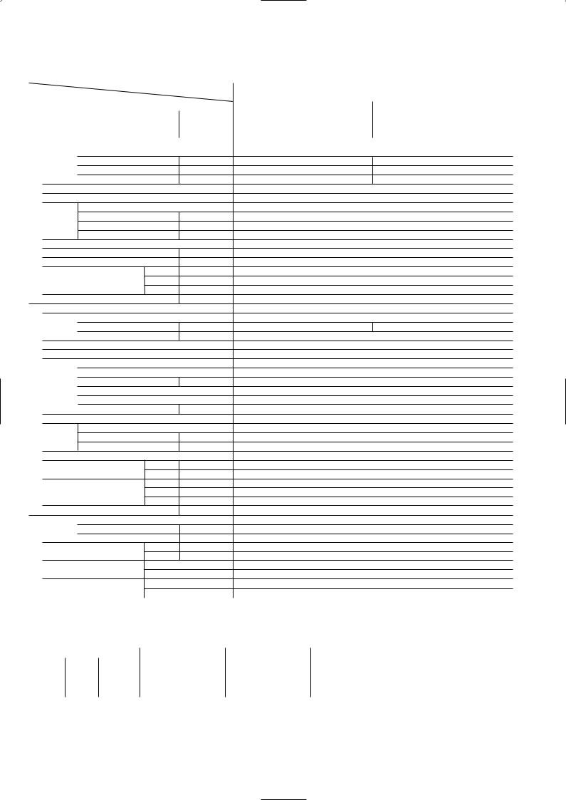
2. Cooling only type
Item |
|
|
Service Ref. |
|
|
|
|
||
Function |
|
|
|
|
Capacity |
|
|
Btu/h |
|
|
|
W |
||
|
|
|
|
|
Total input |
|
|
kW |
|
|
Service Ref. |
|
|
|
|
Power supply(phase, cycle,voltage) |
|
||
|
|
Input |
|
kW |
|
|
Running current |
|
A |
|
|
Starting current |
|
A |
|
External finish |
|
|
|
UNIT |
Heat exchanger |
|
|
|
Fan |
Fan(drive) x No. |
|
|
|
|
|
|
||
INDOOR |
|
Fan motor output |
|
kW |
|
Airflow(Lo-Mi2-Mi1-Hi) |
K/min(CFM) |
||
|
|
|||
|
|
External static pressure |
Pa(mmAq) |
|
|
Operation control & Thermostat |
|
||
|
Noise level(Lo-Mi2-Mi1-Hi) |
|
dB |
|
|
Unit drain pipe I.D. |
|
mm(in.) |
|
|
Dimensions |
W |
mm(in.) |
|
|
|
|
D |
mm(in.) |
|
Weight |
|
H |
mm(in.) |
|
|
|
kg(lbs) |
|
|
Service Ref. |
|
|
|
|
Power supply (phase, cycle, voltage) |
|
||
|
|
Running current |
|
A |
|
|
Starting current |
|
A |
|
External finish |
|
|
|
|
Refrigerant control |
|
|
|
|
Compressor |
|
|
|
UNIT |
|
Model |
|
|
|
Motor output |
|
kW |
|
|
|
|
||
OUTDOOR |
|
Starter type |
|
|
|
Protection devices |
|
|
|
|
|
|
|
|
|
|
Crankcase heater |
|
W |
|
Heat exchanger |
|
|
|
|
Fan |
Fan(drive) x No. |
|
|
|
|
Fan motor output |
|
kW |
|
|
Airflow |
|
K/min(CFM) |
|
Defrost method |
|
|
|
|
Noise level |
Cooling |
dB |
|
|
Dimensions |
W |
mm(in.) |
|
|
|
|
D |
mm(in.) |
|
|
|
H |
mm(in.) |
|
Weight |
|
|
kg(lbs) |
PIPING |
Refrigerant |
|
L |
|
|
Oil (Model) |
|
||
REFRIGERANT |
|
Charge |
|
kg(lbs) |
outdoor unit |
Piping length |
|||
|
Pipe size O.D. |
Liquid |
mm(in.) |
|
|
|
|
Gas |
mm(in.) |
|
Connection method |
Indoor side |
||
|
|
|
Outdoor side |
|
|
Between the indoor & |
Height difference |
||
Notes1. Rating Conditions (ISO T1)
Cooling : Indoor |
: D.B. 27˚C(80˚F) W.B. 19˚C (66˚F) |
||||
Refrigerant piping length (one way) : 5m (16ft) |
|||||
2. Guaranteed operating range |
|
||||
|
|
|
Indoor |
||
Cooling |
Upper limit |
D.B. 35˚C W.B. 22.5˚C |
|||
Lower limit |
D.B. 19˚C W.B. 15˚C |
||||
|
|||||
3. Above data based on indicated voltage |
|
||||
Indoor Unit |
Single phase 240V |
50Hz |
|||
Outdoor Unit |
Single phase 240V |
50Hz |
|||
PLA-P1.6KA.UK |
PLA-P2KA.UK |
Cooling |
Cooling |
15,000 |
18,400 |
4,400 |
5,400 |
1.86 |
2.62 |
PLA-P1.6KA.UK |
PLA-P2KA.UK |
Single phase, 50Hz, 220-230-240V |
|
0.15 |
0.14 |
0.64 |
0.65 |
0.70 |
0.72 |
Galvanized sheets with gray heat insulation |
|
|
Plate fin coil |
|
Turbo fan (direct) x 1 |
|
0.030 |
13-14-15-16(459-494-530-565) |
|
|
0(direct blow) |
Remote controller & built-in |
|
|
32-34-35.5-37 |
|
32(1-1/4) |
UNIT : 660(26) |
PANEL : 760(30) |
UNIT : 660(26) |
PANEL : 760(30) |
UNIT : 253(10) |
PANEL : 30(1-3/16) |
UNIT : 19(42) |
PANEL : 3.7(8) |
PU-P1.6VGA |
PU-P2VGA |
Single phase, 50Hz, 220-230-240V |
|
7.66 |
11.11 |
36 |
74 |
|
Munsell 5Y 8/1 |
Linear Expansion Valve |
|
|
Hermetic |
RE277VHSM |
NE38VMJM |
1.3 |
1.7 |
|
Line start |
Inner thermostat, High pressure switch, Discharge thermo. |
|
30 |
38 |
|
Plate fin coil |
Propeller (direct) x 1 |
|
|
0.070 |
45(1,590) |
55(1,940) |
|
— |
46 |
48 |
|
900(35-7/16) |
|
330+20(13+3/4) |
650 (25-5/8) |
855(33-5/8) |
55(121) |
71(157) |
|
R407C |
2.6(5.7) |
3.1(6.8) |
0.57(Ester)MEL56 |
1.2(Ester)MEL56 |
|
9.52 (3/8) |
|
15.88 (5/8) |
|
Flared |
|
Flared |
|
Max. 40m |
|
Max. 40m |
Outdoor : D.B. 35˚C(95˚F) |
W.B. 24˚C (75˚F) |
Outdoor
D.B. 46˚C
D.B. -5˚C
16
Item |
|
|
Service Ref. |
|
|
|
|
||
Function |
|
|
|
|
Capacity |
|
|
Btu/h |
|
|
|
W |
||
|
|
|
|
|
Total input |
|
|
kW |
|
|
Service Ref. |
|
|
|
|
Power supply(phase, cycle,voltage) |
|
||
|
|
Input |
|
kW |
|
|
Running current |
|
A |
|
|
Starting current |
|
A |
UNIT |
External finish |
|
|
|
Heat exchanger |
|
|
||
|
|
|
||
|
Fan |
Fan(drive) x No. |
|
|
INDOOR |
|
Fan motor output |
|
kW |
|
Airflow(Lo-Mi2-Mi1-Hi) |
K/min(CFM) |
||
|
|
|||
|
|
External static pressure |
Pa(mmAq) |
|
|
Operation control & Thermostat |
|
||
|
Noise level(Lo-Mi2-Mi1-Hi) |
|
dB |
|
|
Unit drain pipe I.D. |
|
mm(in.) |
|
|
Dimensions |
W |
mm(in.) |
|
|
|
|
D |
mm(in.) |
|
|
|
H |
mm(in.) |
|
Weight |
|
|
kg(lbs) |
|
Service Ref. |
|
|
|
|
Power supply (phase, cycle, voltage) |
|
||
|
|
Running current |
|
A |
|
|
Starting current |
|
A |
|
External finish |
|
|
|
|
Refrigerant control |
|
|
|
|
Compressor |
|
|
|
UNIT |
|
Model |
|
|
|
Motor output |
|
kW |
|
|
|
|
||
OUTDOOR |
|
Starter type |
|
|
|
Protection devices |
|
|
|
|
|
|
|
|
|
|
Crankcase heater |
|
W |
|
Heat exchanger |
|
|
|
|
Fan |
Fan(drive) x No. |
|
|
|
|
Fan motor output |
|
kW |
|
|
Airflow |
|
K/min(CFM) |
|
Defrost method |
|
|
|
|
Noise level |
Cooling |
dB |
|
|
Dimensions |
W |
mm(in.) |
|
|
|
|
D |
mm(in.) |
|
|
|
H |
mm(in.) |
|
Weight |
|
|
kg(lbs) |
PIPING |
Refrigerant |
|
L |
|
|
Oil (Model) |
|
||
REFRIGERANT |
|
Charge |
|
kg(lbs) |
outdoor unit |
Piping length |
|||
|
Pipe size O.D. |
Liquid |
mm(in.) |
|
|
|
|
Gas |
mm(in.) |
|
Connection method |
Indoor side |
||
|
|
|
Outdoor side |
|
|
Between the indoor & |
Height difference |
||
Notes1. Rating Conditions (ISO T1) |
|
|
||
Cooling : Indoor : D.B. 27˚C(80˚F) |
W.B. 19˚C (66˚F) |
|||
Refrigerant piping length (one way) : 5m (16ft) |
||||
2. Guaranteed operating range |
|
|
||
|
|
|
||
|
|
Indoor |
|
|
Cooling |
Upper limit |
D.B. 35˚C |
W.B. 22.5˚C |
|
|
Lower limit |
D.B. 19˚C |
W.B. 15˚C |
|
PLA-P2.5KA.UK
Cooling 21,500 6,300 2.77
PLA-P2.5KA.UK
Single phase, 50Hz, 220-230-240V 0.14 0.61 0.67
Galvanized sheets with gray heat insulation Plate fin coil
Turbo fan (direct) x 1 0.030
14-15-16-17 (494-530-565-600)
0(direct blow)
Remote controller & built-in 35-36.5-38-39.5 32(1-1/4)
UNIT : 660(26) PANEL : 760(30)
UNIT : 660(26) PANEL : 760(30) UNIT : 253(10) PANEL : 30(1-3/16)
UNIT : 20(44) PANEL : 3.7(8)
PU-P2.5VGA1
Single Phase, 50Hz, 220-230-240V 11.78
77
Munsell 5Y 8/1
Linear Expansion Valve
Hermetic
NE41VMJM
1.9 Line start
Internal thermostat, High pressure switch, Discharge thermo. 38
Plate fin coil Propeller (direct) x 1 0.070
50(1,770)
—
48 900(35-7/16) 330+20(13+3/4) 855(33-5/8) 82(181) R407C 3.3(7.3)
1.2(Ester)MEL56 9.52 (3/8) 15.88 (5/8) Flared
Flared
Max. 50m
Max. 50m
Outdoor : D.B. 35˚C(95˚F) W.B. 24˚C (75˚F)
Outdoor
D.B. 46˚C
D.B. -5˚C
3. Above data based on indicated voltage |
|
|
Indoor Unit |
Single phase 240V |
50Hz |
Outdoor Unit |
Single phase 240V |
50Hz / 3 phases 415V 50Hz |
17
|
|
|
|
|
|
|
|
|
|
|
|
|
|
|
|
|
|
|
Item |
|
|
Service Ref. |
PLA-P1.6KA.UK / PLA-P1.6KA1.UK |
PLA-P2KA.UK / PLA-P2KA1.UK |
|
|
|
|
|
|
|
|
|
||
|
Function |
|
|
|
Cooling |
Cooling |
|
|
|
Capacity |
|
|
Btu/h |
15,000 |
18,000 |
|
|
|
|
|
W |
4,400 |
5,300 |
|
||
|
Total input |
|
|
|
||||
|
|
|
kW |
1.82 |
2.44 |
|
||
|
|
Service Ref. |
|
|
PLA-P1.6KA.UK / PLA-P1.6KA1.UK |
PLA-P2KA.UK / PLA-P2KA1.UK |
|
|
|
|
Power supply(phase, cycle,voltage) |
|
Single phase, 50Hz, 220-230-240V |
|
|||
|
|
|
Input |
|
kW |
0.15 |
0.14 |
|
|
|
|
Running current |
|
A |
0.64 |
0.65 |
|
|
|
|
Starting current |
|
A |
0.70 |
0.72 |
|
|
|
External finish |
|
|
Galvanized sheets with gray heat insulation |
|
||
|
UNIT |
Heat exchanger |
|
|
Plate fin coil |
|
||
|
Fan |
Fan(drive) x No. |
|
|
Turbo fan (direct) x 1 |
|
||
|
|
|
|
|
||||
|
INDOOR |
|
Fan motor output |
|
kW |
0.030 |
|
|
|
|
Airflow(Lo-Mi2-Mi1-Hi) |
K/min(CFM) |
13-14-15-16(459-494-530-565) |
|
|||
|
|
|
|
|||||
|
|
|
External static pressure |
Pa(mmAq) |
0(direct blow) |
|
||
|
|
Operation control & Thermostat |
|
Remote controller & built-in |
|
|||
|
|
Noise level(Lo-Mi2-Mi1-Hi) |
|
dB |
32-34-35.5-37 |
|
||
|
|
Unit drain pipe I.D. |
|
mm(in.) |
32(1-1/4) |
|
||
|
|
Dimensions |
W |
mm(in.) |
UNIT : 660(26) PANEL : 760(30) |
|
||
|
|
|
|
D |
mm(in.) |
UNIT : 660(26) PANEL : 760(30) |
|
|
|
|
Weight |
|
H |
mm(in.) |
UNIT : 253(10) PANEL : 30(1-3/16) |
|
|
|
|
|
|
kg(lbs) |
UNIT : 19(42) PANEL : 3.7(8) |
|
||
|
|
Service Ref. |
|
|
PU-P1.6VGAA.UK / PU-P1.6YGAA.UK |
PU-P2VGAA.UK / PU-P2YGAA.UK |
|
|
|
|
Power supply (phase, cycle, voltage) |
|
Single Phase, 50Hz, 220-230-240V / 3 phases, 50Hz, 380-400-415V(4wires) |
|
|||
|
|
|
Running current |
|
A |
7.36 / 2.49 |
10.26 / 3.70 |
|
|
|
|
Starting current |
|
A |
36 / 20 |
62 / 31 |
|
|
|
External finish |
|
|
Munsell 5Y 7/1 |
|
||
|
|
Refrigerant control |
|
|
Linear Expansion Valve |
|
||
|
|
Compressor |
|
|
Hermetic |
|
||
|
UNIT |
|
Model |
|
|
RE277VHSMT / RE277YFKM |
NE36VMJMT / NE36YEKMT |
|
|
|
Motor output |
|
kW |
1.3 |
1.6 |
|
|
|
|
|
|
|
||||
|
OUTDOOR |
|
Starter type |
|
|
Line start |
|
|
|
|
Protection devices |
|
|
Inner thermostat, HP switch, Discharge thermo./ Thermal relay, HP switch, Discharge thermo |
|
||
|
|
|
|
|
|
|||
|
|
|
Crankcase heater |
|
W |
30 |
38 |
|
|
|
Heat exchanger |
|
|
Plate fin coil |
|
||
|
|
Fan |
Fan(drive) x No. |
|
|
Propeller (direct) x 1 |
|
|
|
|
|
Fan motor output |
|
kW |
0.070 |
|
|
|
|
|
Airflow |
|
K/min(CFM) |
45(1,590) |
55(1,940) |
|
|
|
Defrost method |
|
|
— |
|
|
|
|
|
Noise level |
Cooling |
dB |
47 |
48 |
|
|
|
|
Dimensions |
W |
mm(in.) |
900(35-7/16) |
|
||
|
|
|
|
D |
mm(in.) |
330+20(13+3/4) |
|
|
|
|
|
|
H |
mm(in.) |
650 (25-5/8) |
855(33-5/8) |
|
|
|
Weight |
|
|
kg(lbs) |
55(121) |
71(157) |
|
|
PIPING |
Refrigerant |
|
|
R407C |
|
||
|
|
Charge |
|
kg(lbs) |
2.5(5.5) |
2.6(5.7) |
|
|
|
|
Oil (Model) |
|
L |
0.57(Ester)MEL56 |
1.2(Ester)MEL56 |
|
|
|
REFRIGERANT |
outdoor unit |
Piping length |
Max. 40m |
|
|||
|
|
Pipe size O.D. |
Liquid |
mm(in.) |
9.52 (3/8) |
|
||
|
|
|
|
Gas |
mm(in.) |
15.88 (5/8) |
|
|
|
|
Connection method |
Indoor side |
Flared |
|
|||
|
|
|
|
Outdoor side |
Flared |
|
||
|
|
Between the indoor & |
Height difference |
Max. 40m |
|
|||
|
|
|
|
|
|
|
|
|
Notes1. Rating Conditions (ISO T1) |
|
|
|
|||
Cooling : Indoor |
: D.B. 27˚C(80˚F) |
W.B. 19˚C (66˚F) |
Outdoor : D.B. 35˚C(95˚F) W.B. 24˚C (75˚F) |
|||
Refrigerant piping length (one way) : 5m (16ft) |
|
|||||
2. Guaranteed operating range |
|
|
|
|||
|
|
|
Indoor |
Outdoor |
||
Cooling |
Upper limit |
D.B. 35˚C W.B. 22.5˚C |
D.B. 46˚C |
|||
|
Lower limit |
D.B. 19˚C |
W.B. 15˚C |
D.B. -5˚C |
||
3. Above data based on indicated voltage |
|
|
||||
Indoor Unit |
Single phase 240V |
50Hz |
|
|||
Outdoor Unit |
Single phase 240V |
50Hz / 3 phases 415V 50Hz |
||||
18
 Loading...