


SPLIT-TYPE, HEAT PUMP AIR CONDITIONERS
SPLIT-TYPE, AIR CONDITIONERS
June 2007
SERVICE MANUAL
No. OC370
REVISED EDITION-B
Indoor unit |
[Service Ref.] |
[Model names] |
PLA-A12AA |
PLA-A12AA PLA-A12AA1 |
|
PLA-A18AA |
PLA-A18AA PLA-A18AA1 |
|
PLA-A24AA PLA-A24AA1 |
||
PLA-A24AA |
||
PLA-A30AA PLA-A30AA1 |
||
PLA-A30AA |
||
PLA-A36AA PLA-A36AA1 |
||
PLA-A36AA |
||
PLA-A42AA PLA-A42AA1 |
||
PLA-A42AA |
||
|
Revision:
•WIRING DIAGRAM has been changed in REVISED EDI- TION-B.
•Some descriptions have been modified.
•Please void OC370 REVISED EDITION-A.
NOTE:
•This manual describes only service data of the indoor units.
•RoHS compliant products have <G> mark on the spec name plate.
•For servicing RoHS compliant products, refer to the RoHS PARTS LIST.
|
|
CONTENTS |
|
|
1. TECHNICAL CHANGES ············· |
|
|
2. REFERENCE MANUAL ·············· |
|
|
3. SAFETY PRECAUTION············· |
|
|
4. PART NAMES AND FUNCTIONS ········· |
|
|
5. SPECIFICATIONS ················ |
|
|
6. NOISE CRITERION CURVES ··········· |
Model name |
|
7. OUTLINES AND DIMENSIONS ·········· |
indication |
|
8. WIRING DIAGRAM················ |
INDOOR UNIT |
|
9. REFRIGERANT SYSTEM DIAGRAM········· |
|
|
10. TROUBLESHOOTING ·············· |
|
|
11. DISASSEMBLY PROCEDURE·········· |
ON/OFF TEMP |
|
12. PARTS LIST ·················· |
TEMP. |
ON/OFF |
13. RoHS PARTS LIST ··············· |
|
|
WIRELESS REMOTE |
WIRED REMOTE |
3 3 2 2 3 |
|
CONTROLLER |
CONTROLLER |
||
|

1 
 TECHNICAL CHANGES
PLA-A12AA PLA-A18AA PLA-A24AA PLA-A30AA PLA-A36AA PLA-A42AA
PLA-A12AA1
PLA-A18AA1
PLA-A24AA1
PLA-A30AA1
PLA-A36AA1
PLA-A42AA1
• Indoor controller board has been changed.
2 |
|
REFERENCE MANUAL |
|
|
2-1. OUTDOOR UNIT SERVICE MANUAL |
|
|
||
|
|
|
||
Service Ref. |
Service Manual No. |
|
||
|
|
|
||
PUZ-A18/24/30/36/42NHA |
|
|
||
PUZ-A18/24/30/36/42NHA-BS |
OC367 |
|
||
PUY-A12/18/24/30/36/42NHA(1) |
|
|||
|
|
|||
PUY-A12/18/24/30/36/42NHA(1)-BS |
|
|
||
2-2. TECHNICAL DATA BOOK |
|
|
||
|
|
|||
Series (Outdoor unit) |
Manual No. |
|
||
|
|
|
||
PUZ-A·NHA(-BS) |
OCS04 |
|
||
PUY-A·NHA(-BS) |
|
|||
2
3 SAFETY PRECAUTION
3-1. ALWAYS OBSERVE FOR SAFETY
Before obtaining access to terminals, all supply circuits must be disconnected.
3-2. CAUTIONS RELATED TO NEW REFRIGERANT
Cautions for units utilising refrigerant R410A
Use new refrigerant pipes.
Make sure that the inside and outside of refrigerant piping is clean and it has no contamination such as sulfur hazardous for use, oxides, dirt, shaving particles, etc.
In addition, use pipes with specified thickness.
Contamination inside refrigerant piping can cause deterioration of refrigerant oil etc.
Store the piping to be used during installation indoors and keep both ends of the piping sealed until just before brazing. (Leave elbow joints, etc. in their packaging.)
If dirt, dust or moisture enters into refrigerant cycle, that can cause deterioration of refrigerant oil or malfunction of compressor.
Use ester oil, ether oil or alkylbenzene oil (small amount) as the refrigerant oil applied to flares and flange connections.
If large amount of mineral oil enters, that can cause deterioration of refrigerant oil etc.
Charge refrigerant from liquid phase of gas cylinder.
If the refrigerant is charged from gas phase, composition change may occur in refrigerant and the efficiency will be lowered.
Do not use refrigerant other than R410A.
If other refrigerant (R22 etc.) is used, chlorine in refrigerant can cause deterioration of refrigerant oil etc.
Use a vacuum pump with a reverse flow check valve.
Vacuum pump oil may flow back into refrigerant cycle and that can cause deterioration of refrigerant oil etc.
Use the following tools specifically designed for use with R410A refrigerant.
The following tools are necessary to use R410A refrigerant.
|
Tools for R410A |
|
Gauge manifold |
|
Flare tool |
Charge hose |
|
Size adjustment gauge |
Gas leak detector |
|
Vacuum pump adaptor |
Torque wrench |
|
Electronic refrigerant |
|
|
charging scale |
|
|
|
Keep the tools with care.
If dirt, dust or moisture enters into refrigerant cycle, that can cause deterioration of refrigerant oil or malfunction of compressor.
Do not use a charging cylinder.
If a charging cylinder is used, the composition of refrigerant will change and the efficiency will be lowered.
Ventilate the room if refrigerant leaks during operation. If refrigerant comes into contact with a flame, poisonous gases will be released.
[1]Cautions for service
(1)Perform service after collecting the refrigerant left in the unit completely.
(2)Do not release refrigerant in the air.
(3)After completing service, charge the cycle with specified amount of refrigerant.
(4)When performing service, install a filter drier simultaneously. Be sure to use a filter drier for new refrigerant.
3

[2] Additional refrigerant charge
When charging directly from cylinder
·Check that cylinder for R410A on the market is syphon type.
·Charging should be performed with the cylinder of syphon stood vertically. (Refrigerant is charged from liquid phase.)
Unit
Gravimeter
[3] Service tools
Use the below service tools as exclusive tools for R410A refrigerant.
No. |
|
Specifications |
1 |
Gauge manifold |
·Only for R410A |
|
|
|
|
|
·Use the existing fitting specifications. (UNF1/2) |
|
|
|
|
|
·Use high-tension side pressure of 5.3MPa·G or over. |
|
|
|
2 |
Charge hose |
·Only for R410A |
|
|
|
|
|
·Use pressure performance of 5.09MPa·G or over. |
3Electronic scale
4 |
Gas leak detector |
·Use the detector for R134a, R407C or R410A. |
|
|
|
5 |
Adaptor for reverse flow check |
·Attach on vacuum pump. |
6Refrigerant charge base
7 Refrigerant cylinder |
·Only for R410A |
Top of cylinder (Pink) |
|
|
Cylinder with syphon |
8Refrigerant recovery equipment
4
4 
 PART NAMES AND FUNCTIONS
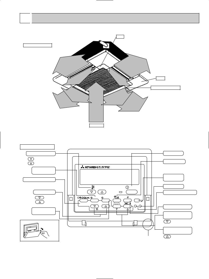
● Indoor Unit
Filter
Removes dust and pollutants
from intake air.
Horizontal Air Outlet
Sets horizontal airflow automatically during cooling or dehumidifying.
Grille
Auto Air Swing Vane Disperses airflow up and down and adjusts the angle of airflow direction.
Air Intake
Intakes air from room.
● Wired remote controller |
|
|
|
Operation Section |
|
|
|
Temperature setting buttons |
|
|
|
Down |
|
|
|
Up |
|
|
|
Timer Menu button |
|
|
|
(Monitor/Set button) |
|
|
|
Mode button (Return button) |
|
|
|
|
|
TEMP. |
|
Set Time buttons |
|
|
|
Back |
|
MENU |
ON/OFF |
Ahead |
BACK |
MONITOR/SET |
DAY |
|
|||
Timer On/Off button |
PAR-21MAA |
CLOCK |
|
(Set Day button) |
|
|
|
Opening the |
|
|
|
lid |
|
|
|
|
ON/OFF |
|
|
FILTER |
|
|
CHECK |
TEST |
OPERATION |
CLEAR |
|
Built-in temperature sensor
ON/OFF button
Fan Speed button
Filter  button (<Enter> button)
Test Run button
Check button (Clear button)
Airflow Up/Down button
Louver button
( Operation button)
To return operation number
Ventilation button
( Operation button)
To go to next operation number
5
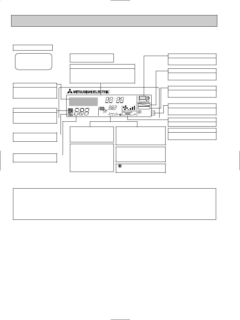
● Wired remote controller
Display Section
For purposes of this explanation, |
Day-of-Week |
all parts of the display are shown |
Shows the current day of the week. |
as lit. During actual operation, only |
|
the relevant items will be lit. |
Time/Timer Display |
Shows the current time, unless the simple or Auto Off timer is set.
If the simple or Auto Off timer is set, the time to be switched off is shown.
Identifies the current operation
Shows the operating mode, etc. *Multilanguage display is available.
|
TIME SUN MON TUE WED THU FRI SAT |
||
|
TIMER |
Hr |
ON |
|
AFTER |
AFTER |
OFF |
|
ERROR CODE |
|
FUNCTION |
|
˚F˚C |
|
FILTER |
“Centrally Controlled” indicator |
˚F˚C |
|
|
|
WEEKLY |
||
Indicates that operation from the |
ONLY1Hr. |
|
SIMPLE |
|
AUTO OFF |
||
remote controller has been prohib- |
|
|
|
ited by a master controller.
|
|
|
|
|
Up/Down Air Direction indica- |
|
Room Temperature display |
“Timer is Off” indicator |
|
|
|
|
tor |
|
Shows the room temperature. The room |
|
|
|
|
Shows the direction of the |
|
temperature display range is 46–102°F. |
|
Indicates that the timer is off. |
|
|
|
outcoming airflow. |
|
The display blinks if the temperature |
|
|
|
|
|
|
|
|
is less than 46°F or 102°F or more. |
|
|
|
|
|
“One Hour Only” indicator |
|
Louver display |
|
|
|
|
|
|
|
|
|
|
|
|
|
Displayed if the airflow is set to |
||
|
|
|
|
|
|
|
|
|
|
|
|
|
|
Indicates the action of the swing louver. |
|
Temperature Setting |
|
|
|
Low or downward during COOL |
|
||
|
|
|
or DRY mode. (Operation varies |
|
Does not appear if the louver is not |
||
Shows the target temperature. |
|
|
|
according to model.) |
|
running. |
|
|
|
|
|
|
The indicator goes off in one hour, |
|
(Power On indicator) |
|
|
|
|
|
at which time the airflow direction |
|
|
|
|
|
|
|
also changes. |
|
Indicates that the power is on. |
“Sensor” indication
Displayed when the remote controller sensor is used.
“Locked” indicator
Indicates that remote controller buttons have been locked.
“Clean The Filter” indicator
To be displayed on when it is time to clean the filter.
Timer indicators
The indicator comes on if the corresponding timer is set.
Fan Speed indicator
Shows the selected fan speed.
Ventilation indicator
Appears when the unit is running in Ventilation mode.
Note:
●“PLEASE WAIT” message
This message is displayed for approximately 3 minutes when power is supplied to the indoor unit or when the unit is recovering from a power failure.
●“NOT AVAILABLE” message
This message is displayed if an invalid button is pressed (to operate a function that the indoor unit does not have).
If a single remote controller is used to operate multiple indoor units simultaneously that are different types, this message will not be displayed as far as any of the indoor units is equipped with the function.
6

● Wireless remote controller
OPERATION MODE display
OPERATION MODE display
Indicates which operation mode is in effect.

 display
The vertical direction of air flow is indicated.

 display
Displays selected fan speed.
ON/OFF button
The unit is turned ON and OFF alternately each time the button is pressed.
FAN SPEED SELECT button
Changes the fan speed.
MODE SELECT button
Switches the operation mode between COOLING/DRY/FAN/HEATING and AUTO mode.
wIn case the outdoor unit is cooling only type, the heating and auto mode are not available.
CHECK-TEST RUN button
Performs an inspection check or test operation.
Do not use it for normal operation.
VANE CONTROL button
Changes the air flow direction.
CHECK TESTRUN display
Indicate that the unit is being checked or test-run.
MODEL SELECT display
Blinks when model is selected.
COOL CHECK |
TEST |
˚F |
|
MODEL |
RUN |
||
˚C |
|||
DRY SELECT |
|
STOP AMPM |
|
AUTO FAN |
SWING |
|
|
FAN |
START AMPM |
||
|
|||
HEAT NOT AVAILABLE |
|
||
ON/OFF  TEMP
TEMP
|
FAN |
AUTO STOP |
MODE |
VANE |
AUTO START |
CHECK |
LOUVER |
h |
TEST RUN |
|
min |
SET |
RESET CLOCK |
|
 display
Lights up while the signal is transmitted to the indoor unit when the button is pressed.
Temperature setting display
indicates the desired temperature setting which is set.
CLOCK display
Displays the current time.
TIMER display
Displays when in timer operation or when setting timer.
“  ” “
” “ ” display
Displays the order of timer operation.
“
 ” “
” “
 ” display
Displays whether timer is on or off.
 button
Sets any desired room temperature.
TIMER CONTROL buttons
AUTO STOP (OFF timer): when this switch is set, the air conditioner will be automatically stopped at the preset time.
AUTO START (ON timer): when this switch is set, the air conditioner will be automatically started at the preset time.
"h" and "min" buttons
Buttons used to set the “hour and minute” of the current time and timer settings.
LOUVER button
Changes left / right airflow direction.
(Not available for this model.)
CLOCK button
RESET button
SET button
7
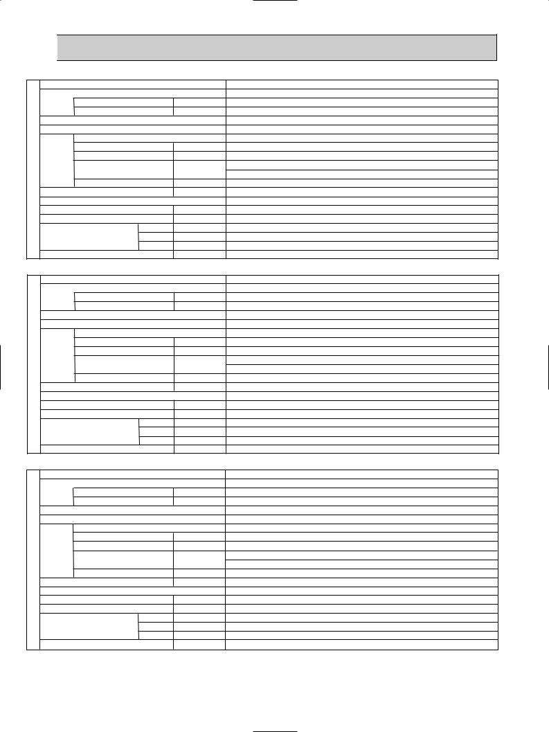
5 |
|
|
SPECIFICATIONS |
|||
|
|
|
|
|
||
Service Ref. |
|
|
||||
Power supply (phase, cycle, voltage) |
|
|||||
|
|
|
Max. Fuse Size |
|
A |
|
|
|
|
Min. Circuit Ampacity |
|
A |
|
External finish (Panel) |
|
|
||||
Heat exchanger |
|
|
||||
Fan |
Fan (drive) o No. |
|
|
|||
UNIT |
Fan motor output |
|
kW |
|||
|
|
|
|
|||
INDOOR |
Fan motor |
|
F.L.A. |
|||
Airflow (Low-Medium2-Medium1-High) |
K/min(CFM) |
|||||
|
|
|
||||
|
|
|
External static pressure |
|
Pa(mmAq) |
|
Booster heater |
|
kW |
||||
Operation control & Thermostat |
|
|
||||
Noise level (Low-Medium2-Medium1-High) |
dB |
|||||
Field drain pipe O.D. |
|
mm(in.) |
||||
Dimensions |
W |
mm(in.) |
||||
|
|
|
|
D |
mm(in.) |
|
|
|
|
|
H |
mm(in.) |
|
Weight |
|
|
kg(lbs) |
|||
Service Ref. |
|
|
||||
Power supply (phase, cycle, voltage) |
|
|||||
|
|
|
Max. Fuse Size |
|
A |
|
|
|
|
Min. Circuit Ampacity |
|
A |
|
External finish (Panel) |
|
|
||||
Heat exchanger |
|
|
||||
Fan |
Fan (drive) o No. |
|
|
|||
UNIT |
Fan motor output |
|
kW |
|||
|
|
|
|
|||
INDOOR |
Fan motor |
|
F.L.A. |
|||
Airflow (Low-Medium2-Medium1-High) |
K/min(CFM) |
|||||
|
|
|
||||
|
|
|
External static pressure |
Pa(mmAq) |
||
Booster heater |
|
kW |
||||
Operation control & Thermostat |
|
|
||||
Noise level (Low-Medium2-Medium1-High) |
dB |
|||||
Field drain pipe O.D. |
|
mm(in.) |
||||
Dimensions |
W |
mm(in.) |
||||
|
|
|
|
D |
mm(in.) |
|
|
|
|
|
H |
mm(in.) |
|
Weight |
|
|
kg(lbs) |
|||
Service Ref. |
|
|
||||
Power supply (phase, cycle, voltage) |
|
|||||
|
|
|
Max. Fuse Size |
|
A |
|
|
|
|
Min. Circuit Ampacity |
|
A |
|
External finish (Panel) |
|
|
||||
Heat exchanger |
|
|
||||
Fan |
Fan (drive) o No. |
|
|
|||
UNIT |
Fan motor output |
|
kW |
|||
|
|
|
|
|||
INDOOR |
Fan motor |
|
F.L.A. |
|||
Airflow (Low-Medium2-Medium1-High) |
K/min(CFM) |
|||||
|
|
|
||||
|
|
|
External static pressure |
|
Pa(mmAq) |
|
Booster heater |
|
kW |
||||
Operation control & Thermostat |
|
|
||||
Noise level (Low-Medium2-Medium1-High) |
dB |
|||||
Field drain pipe O.D. |
|
mm(in.) |
||||
Dimensions |
W |
mm(in.) |
||||
|
|
|
|
D |
mm(in.) |
|
|
|
|
|
H |
mm(in.) |
|
Weight |
|
|
kg(lbs) |
|||
PLA-A12AA/ PLA-A12AA1
Single phase,60Hz, 208/230V 15 1
Munsell 0.70Y 8.59/0.97
Plate fin coil
Turbo fan (direct) o 1 0.070 0.79
Dry: 11-12-13-14(390-420-460-490)
Wet: 10-11-12-13(350-380-420-450)
0(direct blow)
–
Remote controller & built-in 27-28-29-31
32 (1-1/4)
UNIT : 840 (33-1/16) |
PANEL : 950 (37-3/8) |
UNIT : 840 (33-1/16) |
PANEL : 950 (37-3/8) |
UNIT : 258 (10-3/16) |
PANEL : 30 (1-3/16) |
UNIT : 22 (49) |
PANEL: 5 (11) |
PLA-A18AA/ PLA-A18AA1
Single phase,60Hz, 208/230V
15
1
Munsell 0.70Y 8.59/0.97 Plate fin coil
Turbo fan (direct) o 1
0.070
0.79
Dry: 15-16-18-20(530-570-640-710) Wet:14-15-17-19(490-530-600-670)
0(direct blow)
–
Remote controller & built-in 28-30-32-34
32 (1-1/4)
UNIT : 840 (33-1/16) |
PANEL : 950 (37-3/8) |
UNIT : 840 (33-1/16) |
PANEL : 950 (37-3/8) |
UNIT : 258 (10-3/16) |
PANEL : 30 (1-3/16) |
UNIT : 24 (53) |
PANEL: 5 (11) |
PLA-A24AA/ PLA-A24AA1
Single phase,60Hz, 208/230V 15
1
Munsell 0.70Y 8.59/0.97
Plate fin coil
Turbo fan (direct) o 1 0.070
0.79
Dry: 15-16-18-20(530-570-640-710)
Wet: 14-15-17-19(490-530-600-670)
0(direct blow)
–
Remote controller & built-in
28-30-32-34
32(1-1/4)
UNIT : 840 (33-1/16) |
PANEL : 950 (37-3/8) |
UNIT : 840 (33-1/16) |
PANEL : 950 (37-3/8) |
UNIT : 258 (10-3/16) |
PANEL : 30 (1-3/16) |
UNIT : 24 (53) |
PANEL: 5 (11) |
8

Service Ref. |
|
|
||
Power supply (phase, cycle, voltage) |
|
|||
|
Max. Fuse Size |
|
A |
|
|
Min. Circuit Ampacity |
|
A |
|
External finish (Panel) |
|
|
||
Heat exchanger |
|
|
||
Fan |
Fan (drive) o No. |
|
|
|
UNIT |
Fan motor output |
|
kW |
|
|
|
|||
INDOOR |
Fan motor |
|
F.L.A. |
|
Airflow (Low-Medium2-Medium1-High) |
K/min(CFM) |
|||
|
||||
|
External static pressure |
|
Pa(mmAq) |
|
Booster heater |
|
kW |
||
Operation control & Thermostat |
|
|
||
Noise level (Low-Medium2-Medium1-High) |
dB |
|||
Field drain pipe O.D. |
|
mm(in.) |
||
Dimensions |
W |
mm(in.) |
||
|
|
D |
mm(in.) |
|
|
|
H |
mm(in.) |
|
Weight |
|
|
kg(lbs) |
|
PLA-A30AA/ PLA-A30AA1
Single phase,60Hz, 208/230V
15
1
Munsell 0.70Y 8.59/0.97 Plate fin coil
Turbo fan (direct) o 1
0.070
0.79
Dry: 15-16-18-20(530-570-640-710) Wet: 14-15-17-19(490-530-600-670)
0(direct blow)
–
Remote controller & built-in 28-30-32-34
32(1-1/4)
UNIT : 840 (33-1/16) |
PANEL : 950 (37-3/8) |
UNIT : 840 (33-1/16) |
PANEL : 950 (37-3/8) |
UNIT : 258 (10-3/16) |
PANEL : 30 (1-3/16) |
UNIT : 24 (53) |
PANEL: 5 (11) |
PLA-A36AA/ PLA-A36AA1
Single phase,60Hz, 208/230V 15
2
Munsell 0.70Y 8.59/0.97 Plate fin coil
Turbo fan (direct) o 1 0.110
1.25
Dry: 20-23-26-28(710-810-920-990) Wet: 19-22-25-27(670-770-880-950)
0(direct blow)
–
Remote controller & built-in
33-36-39-41 32(1-1/4)
UNIT : 840 (33-1/16) PANEL : 950 (37-3/8)
UNIT : 840 (33-1/16) PANEL : 950 (37-3/8)
UNIT : 298 (11-3/4) |
PANEL : 30 |
(1-3/16) |
UNIT : 30 (66) |
PANEL : |
5 (11) |
PLA-A42AA/ PLA-A42AA1
Single phase,60Hz, 208/230V 15
2
Munsell 0.70Y 8.59/0.97
Plate fin coil
Turbo fan (direct) o 1 0.110
1.25
Dry: 20-23-26-28(710-810-920-990)
Wet: 19-22-25-27(670-770-880-950)
0(direct blow)
–
Remote controller & built-in
33-36-39-41
32(1-1/4)
UNIT : 840 (33-1/16) PANEL : 950 (37-3/8)
UNIT : 840 (33-1/16) PANEL : 950 (37-3/8)
UNIT : 298 (11-3/4) |
PANEL : 30 |
(1-3/16) |
UNIT : 30 (66) |
PANEL : |
5 (11) |
9

6 
 NOISE CRITERION CURVES
PLA-A12AA |
|
|
NOTCH |
SPL(dB) |
LINE |
||||
PLA-A12AA1 |
|
|
|
High |
31 |
|
|||
|
|
Medium1 |
29 |
|
|||||
|
|
|
|
|
|
|
|||
|
|
|
|
|
|
Medium2 |
28 |
|
|
|
|
|
|
|
|
|
Low |
27 |
|
|
90 |
|
|
|
|
|
|
|
|
bar) |
80 |
|
|
|
|
|
|
|
|
= 0.0002 |
|
|
|
|
|
|
|
|
|
70 |
|
|
|
|
|
|
|
|
|
dB |
|
|
|
|
|
|
|
|
|
|
|
|
|
|
|
|
|
NC-70 |
|
dB (0 |
|
|
|
|
|
|
|
|
|
LEVEL, |
60 |
|
|
|
|
|
|
|
|
|
|
|
|
|
|
|
|
NC-60 |
|
|
|
|
|
|
|
|
|
|
|
PRESSURE |
50 |
|
|
|
|
|
|
|
|
|
|
|
|
|
|
|
|
NC-50 |
|
40 |
|
|
|
|
|
|
|
|
|
SOUND |
|
|
|
|
|
|
|
|
|
|
|
|
|
|
|
|
|
NC-40 |
|
|
|
|
|
|
|
|
|
|
|
BAND |
30 |
|
|
|
|
|
|
|
|
|
|
|
|
|
|
|
|
NC-30 |
|
OCTAVE |
20 |
APPROXIMATE |
|
|
|
|
|
|
|
|
THRESHOLD OF |
|
|
|
|
|
|
||
|
HEARING FOR |
|
|
|
|
|
NC-20 |
||
|
|
|
|
|
|
|
|||
|
|
CONTINUOUS |
|
|
|
|
|
||
|
|
|
|
|
|
|
|
||
|
|
NOISE |
|
|
|
|
|
|
|
|
10 |
63 |
125 |
250 |
500 |
1000 |
2000 |
4000 |
8000 |
|
|
||||||||
BAND CENTER FREQUENCIES, Hz
PLA-A36AA |
|
|
NOTCH |
SPL(dB) |
LINE |
||||
PLA-A42AA |
|
|
|
High |
41 |
|
|||
|
|
Medium1 |
39 |
|
|||||
PLA-A36AA1 |
|
|
|
||||||
|
|
Medium2 |
36 |
|
|||||
PLA-A42AA1 |
|
|
|
Low |
33 |
|
|||
|
|
|
|
|
|
||||
|
90 |
|
|
|
|
|
|
|
|
bar) |
80 |
|
|
|
|
|
|
|
|
= 0.0002 |
|
|
|
|
|
|
|
|
|
70 |
|
|
|
|
|
|
|
|
|
dB |
|
|
|
|
|
|
|
|
|
|
|
|
|
|
|
|
|
NC-70 |
|
dB (0 |
60 |
|
|
|
|
|
|
|
|
LEVEL, |
|
|
|
|
|
|
|
|
|
|
|
|
|
|
|
|
|
NC-60 |
|
|
|
|
|
|
|
|
|
|
|
PRESSURE |
50 |
|
|
|
|
|
|
|
|
|
|
|
|
|
|
|
|
NC-50 |
|
40 |
|
|
|
|
|
|
|
|
|
SOUND |
|
|
|
|
|
|
|
|
|
|
|
|
|
|
|
|
|
NC-40 |
|
|
|
|
|
|
|
|
|
|
|
BAND |
30 |
|
|
|
|
|
|
|
|
|
|
|
|
|
|
|
|
NC-30 |
|
OCTAVE |
20 |
APPROXIMATE |
|
|
|
|
|
|
|
|
THRESHOLD OF |
|
|
|
|
|
|
||
|
HEARING FOR |
|
|
|
|
|
NC-20 |
||
|
|
|
|
|
|
|
|||
|
|
CONTINUOUS |
|
|
|
|
|
||
|
|
|
|
|
|
|
|
||
|
|
NOISE |
|
|
|
|
|
|
|
|
10 |
63 |
125 |
250 |
500 |
1000 |
2000 |
4000 |
8000 |
|
|
||||||||
BAND CENTER FREQUENCIES, Hz
PLA-A18AA PLA-A18AA1 |
NOTCH |
SPL(dB) |
LINE |
||||||
|
|
|
|
|
|
High |
34 |
|
|
PLA-A24AA PLA-A24AA1 Medium1 |
32 |
|
|||||||
PLA-A30AA PLA-A30AA1 |
Medium2 |
30 |
|
||||||
|
|
|
|
|
|
|
Low |
28 |
|
|
90 |
|
|
|
|
|
|
|
|
bar) |
80 |
|
|
|
|
|
|
|
|
= 0.0002 |
70 |
|
|
|
|
|
|
|
|
dB (0 dB |
|
|
|
|
|
|
|
|
|
|
|
|
|
|
|
|
|
NC-70 |
|
60 |
|
|
|
|
|
|
|
|
|
LEVEL, |
|
|
|
|
|
|
|
|
|
|
|
|
|
|
|
|
|
NC-60 |
|
|
|
|
|
|
|
|
|
|
|
PRESSURE |
50 |
|
|
|
|
|
|
|
|
|
|
|
|
|
|
|
|
NC-50 |
|
40 |
|
|
|
|
|
|
|
|
|
SOUND |
|
|
|
|
|
|
|
|
|
|
|
|
|
|
|
|
|
NC-40 |
|
|
|
|
|
|
|
|
|
|
|
BAND |
30 |
|
|
|
|
|
|
|
|
|
|
|
|
|
|
|
|
NC-30 |
|
OCTAVE |
20 |
APPROXIMATE |
|
|
|
|
|
|
|
|
THRESHOLD OF |
|
|
|
|
|
|
||
|
HEARING FOR |
|
|
|
|
|
NC-20 |
||
|
|
|
|
|
|
|
|||
|
|
CONTINUOUS |
|
|
|
|
|
||
|
|
|
|
|
|
|
|
||
|
|
NOISE |
|
|
|
|
|
|
|
|
10 |
63 |
125 |
250 |
500 |
1000 |
2000 |
4000 |
8000 |
|
|
||||||||
BAND CENTER FREQUENCIES, Hz
UNIT
CEILING
5 ft
MICROPHONE
10
7 OUTLINES AND DIMENSIONS
INDOOR UNIT
PLA-A12AA PLA-A18AA PLA-A24AA PLA-A12AA1 PLA-A18AA1 PLA-A24AA1 PLA-A30AA PLA-A36AA PLA-A42AA PLA-A30AA1 PLA-A36AA1 PLA-A42AA1
Unit : inch(mm)
|
|
|
|
|
|
Ceiling hole |
|
|
25/32~1-25/32(20~45) |
33-27/32~35-13/16(860~910) |
|||||
|
|
|
|||||
|
Fresh air intake |
|
31-7/8(810) |
||||
|
6-1/4(159) Suspension bolt pitch |
||||||
|
|
|
|
|
|||
|
6-1/4(159) |
|
|
|
|
|
|
1/16(840)-33 |
Branch duct hole |
|
Terminal block |
|
|||
|
27/32(98) |
|
|
|
|
||
|
|
|
|
|
|
|
|
|
9/16(192) |
3- |
|
|
|
|
|
|
C |
D |
|
|
|
|
|
|
7- |
|
|
|
|
|
|
|
|
|
|
|
7-3/4(197) |
|
|
|
|
Suspension bolt |
|
33-1/16(840) |
|||
|
|
|
|
|
|||
|
|
W3/8(M10) |
|
|
Feeding hole |
||
|
|
|
|
|
|
||
|
|
|
1 |
|
|
(Drain pump) |
|
|
11/16(170)-6 |
1/2(140)-5 |
|
2-3/8(60) 11-1/4(286) |
14-23/32(374) |
||
|
|
|
|
2-[1-1/16(27) |
|
||
|
|
|
|
|
|
|
|
|
|
|
2 |
|
|
|
|
lower edge |
(50~70) 31/32~2-1 -3/4 |
1-1/2(37) |
Air intake grille |
Air intake hole |
|||
|
|
|
|
|
1-3/4(45) |
9-3/4(248) |
|
Wiring entrance holes
22-23/32(577)
Suspension bolt
Branch duct hole
|
|
|
|
(20~45) |
25/32-25/32~1 |
|
|
3-15/16(100) |
|
3-15/16(100) (Cut out hole) |
1/8(130)-5 |
|
|
|
|
|
|
3-17/32(90) |
15/16(100)-3 |
||||
|
|
|
|
|
|
|
|
3-17/32(90) |
|
||
25/32~1-25/32(20~45) |
|
|
|
|
|
|
|
||||
1(26) |
1/4(159)-6 |
|
13/16(605)-23 |
pitchboltSuspension |
13/16(860~910)-27/32~35-33 |
holeCeiling |
[6-7/8([175) |
13-25/32(350) |
|
||
|
|
|
|
14-[1/8([2.8) |
|||||||
|
|
|
|
|
|
|
|
|
|
||
|
|
|
|
|
|
|
|
|
|
Burring hole |
|
|
|
|
|
|
|
|
Branch duct hole |
|
[5-29/32([150) |
|
|
|
|
|
|
|
|
|
|
Detail drawing of fresh air intake |
|
||
|
|
|
|
|
|
|
|
3-[1/8([2.8) |
|
|
|
|
|
|
|
|
|
|
|
Burring hole |
|
|
|
6-1/4(159) |
|
|
(20~45) |
25/32-25/32~1 |
|
7/32(158)-6 |
[4-29/32([125) |
|
[3-15/16([100) |
|
|
|
|
|
|
|
|
|
|
||||
|
|
|
|
|
|
|
(Cut out hole) |
|
|||
|
|
|
|
|
|
|
|
|
|
Ceiling surface |
|
Drain pipe |
|
|
|
|
|
|
|
|
|
||
O.D.[1-1/4([32) connection |
|
|
|
|
|
||||||
(VP-25) |
|
|
|
|
|
|
|
|
|
|
|
4-1/8(105) |
|
A |
B |
|
|
|
|
|
|
5/16(135) |
|
|
|
|
|
|
|
|
|
|
|
|
5- |
|
|
) |
|
|
|
|
|
|
|
|
|
|
15/32(190) |
+5 |
0 |
3/16(30)-1 |
|
|
|
|
|
|
|
Ceiling surface |
+3/16 |
0 |
|
|
|
|
|
|
|
||
|
|
(17 |
|
|
|
|
|
|
|
|
|
Grille |
|
|
|
|
|
|
|
|
|
|
|
|
7- |
11/16 |
|
|
|
|
|
|
|
|
|
6-3/32(155) 6-9/16(167)
) |
|
+5 |
0 |
(17 |
|
+3/16 |
0 |
11/16 |
|
M |
Drain hole |
|
M
Auto vane
37-3/8(950) |
16-3/16(411) |
Air outlet hole |
|
22-23/32(577) Air intake hole |
|
-1/32(77) |
M |
|
|
|
|
M |
Vane motor |
|
|
3 |
|
|
|
|
2(51) |
16-3/16(411) |
|
2(51) |
|
|
|
||
|
Air outlet hole |
|
3-1/32(77) |
|
|
|
|
||
|
|
37-3/8(950) |
|
|
High efficiency filter
& Fresh air intake casement(option)
Unit : inch(mm)
Models |
A |
|
B |
C |
D |
PLA-A12/18/24/30AA(1) |
9-1/2 |
10-3/16 |
|
|
|
(241) |
(258) |
|
3-5/32 |
||
|
|
||||
PLA-A36AA(1) |
|
|
|
3-1/2 |
(80) |
11-1/16 11-3/4 |
(89) |
|
|||
|
|
||||
|
|
|
|||
PLA-A42AA(1) |
(281) |
|
(298) |
|
3-5/16 |
|
|
|
|
(84) |
|
|
|
|
|
|
|
MODEL |
12/18 |
24/30/36/42 |
|||
1 Liquid pipe |
1/4F |
|
3/8F |
|
|
2 Gas pipe |
1/2F |
5/8F |
11

8 
 WIRING DIAGRAM
PLA-A12AA |
PLA-A18AA |
PLA-A24AA |
PLA-A30AA |
PLA-A36AA |
PLA-A42AA |
|||||||||
PLA-A12AA1 |
PLA-A18AA1 |
PLA-A24AA1 |
PLA-A30AA1 PLA-A36AA1 |
PLA-A42AA1 |
||||||||||
[LEGEND] |
|
|
|
|
|
|
|
|
|
|
|
|
||
|
|
|
|
|
|
|
|
|
|
|
|
|
||
|
SYMBOL |
|
NAME |
SYMBOL |
NAME |
SYMBOL |
NAME |
|
|
|
||||
|
P.B |
INDOOR POWER BOARD |
C |
CAPACITOR<FAN MOTOR> |
W.B |
WIRELESS REMOTE CONTROLLER BOARD |
|
|||||||
|
I.B |
INDOOR CONTROLLER BOARD |
DP |
DRAIN-UP MACHINE |
|
|
BZ |
BUZZER |
|
|
|
|||
|
|
BCR |
FAN CONTROL ELEMENT |
DS |
DRAIN SENSOR |
|
|
LED1 |
LED<RUN INDICATOR > |
|
|
|
||
|
|
CN2L |
CONNECTOR<LOSSNAY> |
H2 |
DEW PREVENTION HEATER |
|
LED2 |
LED<HOT ADJUST> |
|
|
|
|||
|
|
CN32 |
CONNECTOR<REMOTE SWITCH> |
MF |
FAN MOTOR |
|
|
RU |
RECEIVING UNIT |
|
|
|
||
|
|
CN41 |
CONNECTOR<HA TERMINAL-A> |
MV |
VANE MOTOR |
|
|
SW1 |
SWITCH<HEATING ON/OFF> |
|
|
|
||
|
|
CN51 |
CONNECTOR<CENTRALLY CONTROL> |
R.B |
WIRED REMOTE CONTROLLER BOARD |
|
SW2 |
SWITCH<COOLING ON/OFF> |
|
|
|
|||
|
|
FUSE |
FUSE (6.3A/250V) |
TB4 |
TERMINAL BLOCK<INDOOR/OUTDOOR |
|
|
|
|
|
|
|
||
|
|
LED1 |
POWER SUPPLY<I.B> |
|
CONNECTING LINE> |
|
|
|
|
|
|
|
|
|
|
|
LED2 |
POWER SUPPLY<R.B> |
TB5,TB6 |
TERMINAL BLOCK<REMOTE CONTROLLER |
|
|
|
|
|
|
|
||
|
|
LED3 |
TRANSMISSION<INDOOR-OUTDOOR> |
|
TRANSMISSION LINE > |
|
|
Please set the voltage using the |
|
|
|
|||
|
|
SW1 |
SWITCH <MODEL SELECTION>wSee Table 1. |
TH1 |
ROOM TEMP.THERMISTOR |
|
|
remote controller. |
|
|
|
|||
|
|
SW2 |
SWITCH <CAPACITY CODE>wSee Table 2. |
|
<32°F/15kΩ , 77°F/5.2kΩ DETECT> |
|
|
For the setting method, please refer to |
|
|
||||
|
|
SWE |
SWITCH<EMERGENCY OPERATION> |
TH2 |
PIPE TEMP.THERMISTOR/LIQUID |
|
|
the indoor unit Installation Manual. |
|
|
|
|||
|
|
X1 |
RELAY<DRAIN PUMP> |
|
<32°F/15kΩ , 77°F/5.2kΩ DETECT> |
|
|
|
|
|
|
|
||
|
|
|
|
|
|
|
|
|||||||
|
|
X4 |
RELAY<FAN MOTOR> |
TH5 |
COND./EVA.TEMP.THERMISTOR |
|
|
|
|
|
|
|
||
|
|
ZNR |
VARISTOR |
|
|
<32°F/15kΩ , 77°F/5.2kΩ DETECT> |
|
|
|
|
|
|
|
|
|
MF |
|
1 2 3 |
|
1 2 3 |
|
C |
I.B |
RED WHT BLK |
FAN 1 3 5 (WHT)
|
|
|
GRILLE |
|
|
|
MV |
MV |
MV |
MV |
|
|
|
|
5 |
5 |
5 |
5 |
H2 |
|
|
|
|
5 |
|
||
|
|
|
|
|
|
|
|
|
1 2 3 6 7 4 8 9 5 10 |
|
|||
|
DP |
|
|
|
|
|
|
YLW |
YLW |
YLW YLW |
RED WHT |
||
D.U.M |
1 3 D.HEATER |
1 3 |
POWER |
1 3 |
||
CNP |
|
|
CNC |
|
CNDK |
|
(BLU) |
|
|
(RED) |
|
(RED) |
|
X4
P.B
|
|
|
|
|
|
|
|
|
|
|
|
|
|
|
|
|
|
CNSK |
||||
|
|
|
|
|
CN2S |
|
|
|
|
|
|
(RED) |
||||||||||
|
|
|
|
|
(WHT) |
|
DC |
|
3 |
|
|
|
||||||||||
|
|
|
|
|
|
|
|
|
|
|||||||||||||
|
|
|
|
|
2 |
|
|
|
|
|
|
2 |
|
|
|
|||||||
|
|
|
|
|
|
1 |
|
|
|
|
13.1V |
|
1 |
|
|
|
||||||
|
|
|
|
|
|
|
|
|
|
|
|
|
|
|
|
|
|
5 |
|
|
|
|
|
|
|
|
|
|
|
|
|
|
|
|
|
|
|
|
|
|
|
|
|
|
|
|
|
|
|
|
|
|
|
|
|
|
|
|
|
|
|
|
|
|
||||
|
|
|
|
|
|
|
|
|
|
|
|
|
|
|
|
|
|
|
|
|
|
|
|
|
|
|
|
|
|
|
|
|
|
|
|
|
|
|
|
|
|
|
|
|
|
YLW |
|
ORN |
|
|
|
|
BLK |
WHT |
|
BRN |
ORN |
|
|
|
|
|
|
|
||||
|
|
|
POWER |
|
|
|
|
|
|
|
|
|
|
|
VANE |
|||||||
|
1 |
3 |
|
1 |
2 |
|
1 |
3 |
|
|||||||||||||
|
|
|
|
CND |
POWER A-CONTROL |
CN6V |
||||||||||||||||
FUSE |
|
|
(ORN) |
(GRN) |
||||||||||||||||||
|
|
|
|
|
|
|
CN2D |
CN3C |
|
|
|
|
|
|||||||||
|
|
|
|
|
|
|
(WHT) |
(BLU) |
|
|
|
|
|
|||||||||
|
|
|
|
|
|
|
|
|
|
|
|
|
|
|
|
|
|
|
|
|
|
|
YLW |
TB4 w1 |
|
|
ORN |
S1 |
|
|
|
S2 |
TO |
|
YLW |
OUTDOOR |
||
|
|||
S3 |
UNIT |
||
ORN |
|||
|
|||
BRN |
|
|
BCR |
X1 |
|
|
ZNR |
CN51 |
CN41 |
CN2L |
W.B |
|
|
X4 X1 |
|
|
|
|
|
|
|
|||
|
|
|
|
|
|
|
CN32 |
9 |
BZ |
LED1 |
|
|
LED3 LED2 LED1 |
|
|
|
|
|
LED2 |
||
|
|
|
|
|
|
CNB |
|
|
||
SWE SW2 SW1 |
HEATER |
D.SENSOR INTAKE LIQUID PIPE REMOCON |
|
|
RU |
|||||
|
|
SW1 |
SW2 |
|||||||
CN24 |
CN31 |
CN20 |
CN21 |
CN29 |
CN22 |
WIRELESS |
|
|||
ON |
(YLW) |
(WHT) |
(RED) |
(WHT) (BLK) |
(BLU) |
CN90 |
|
|
|
|
OFF |
|
1 2 3 |
1 2 |
1 2 |
1 2 |
1 2 |
(WHT) |
|
|
|
|
|
BLU BLU |
|
R.B |
|
|
1 |
2 |
|
|
DS |
|
||
|
|
TB6 |
||
|
TH1 |
|
||
Refer to tables 1 and 2 |
|
|
|
|
|
|
|
|
|
for service PCB. |
TH2 |
TB5 |
|
|
|
|
2 |
|
|
|
TH5 |
1 |
TRANSMISSION WIRES DC12V |
|
NOTES: |
|
|
|
|
1. Symbols used in wiring diagram above are, |
: Connector, |
: Terminal (block). |
|
|
2.Indoor and outdoor connecting wires have polarities, make sure to match terminal numbers (S1, S2, S3) for correct wirings.
3.Since the outdoor side electric wiring may change, be sure to check the outdoor unit electric wiring diagram for servicing.
4.This diagram shows the wiring of Indoor and Outdoor connecting wires (specification of 230V), adopting superimposed system of power and signal.
w1. Use copper supply wires.
[Self-diagnosis]
1.For details on how to operate self-diagnosis with the wireless remote control, refer to the technical manuals etc.
2.For the wired remote control : When you quickly press twice the CHECK switch on the remote control, the unit begins self-diagnosis, and Check Codes generated in the past appear on the display.
For check Codes and Symptoms refer to the table below.
Table 1 |
|
|
|
|
|
|
|
|
|
|
|
|
|
|
|
|
|
|
|
|
|
|
SW1 |
|
|
|
|
|
|
|
|
|
|
|
|
|
|
||||
MODELS |
|
|
Service board |
|
|
|
|
|
|
|
||||||||||
|
|
|
|
|
|
|
|
|
|
|
|
|
|
|
|
|
|
|
|
|
PLA-A,AA |
|
|
1 |
2 |
3 |
4 |
5 |
ON |
|
|
|
|
|
|
|
|||||
|
|
|
|
|
|
|
|
|
|
|
|
|
|
|
|
|
||||
|
|
|
|
|
|
|
|
|
|
|
|
OFF |
|
|
|
|
|
|
|
|
|
|
|
|
|
|
|
|
|
|
|
|
|
|
|
|
|
|
|
|
|
Table 2 |
|
|
|
|
|
|
|
|
|
|
|
|
|
|
|
|
|
|
|
|
|
|
|
|
|
|
|
|
|
|
|
|
|
|
|
|
|
|
|
|
|
|
|
|
|
|
|
|
|
|
|
|
|
SW2 |
|
|
|
|
|
|||
MODELS |
|
Service board |
MODELS |
|
Service board |
|||||||||||||||
|
|
|
|
|
|
|
|
|
|
|
|
|
|
|
|
|
|
|
|
|
PLA-A12AA |
|
1 2 |
|
3 4 5 |
ON |
PLA-A30AA |
|
1 2 3 4 5 |
ON |
|||||||||||
|
|
|
|
|
|
|
|
|
|
|
|
|
|
|
||||||
|
|
|
|
|
|
|
|
|
|
|
OFF |
|
|
|
|
|
|
|
OFF |
|
|
|
|
|
|
|
|
|
|
|
|
|
|
|
|
||||||
|
|
|
|
|
|
|
|
|
|
|
|
|||||||||
PLA-A18AA |
|
1 2 |
|
3 4 5 |
ON |
PLA-A36AA |
|
1 2 3 4 5 |
ON |
|||||||||||
|
|
|
|
|
|
|
|
|
|
|
|
|
|
|
||||||
|
|
|
|
|
|
|
|
|
|
|
OFF |
|
|
|
|
|
|
|
OFF |
|
|
|
|
|
|
|
|
|
|
|
|
|
|||||||||
|
|
|
|
|
|
|
|
|
|
|
|
|||||||||
PLA-A24AA |
|
1 2 |
|
3 4 5 |
ON |
PLA-A42AA |
|
1 2 3 4 5 |
ON |
|||||||||||
|
|
|
|
|
|
|
|
|
|
|
|
|
|
|
||||||
|
|
|
|
|
|
|
|
|
|
|
OFF |
|
|
|
|
|
|
|
OFF |
|
|
|
|
|
|
|
|
|
|
|
|
|
|
|
|
|
|
|
|
|
|
Check code |
Symptom |
Check code |
Symptom |
P1 |
Abnormality of room temperature thermistor(TH1) |
E0-E5 |
Abnormality of the signal transmission between remote |
P2 |
Abnormality of pipe temperature thermistor / Liquid(TH2) |
|
controller and indoor unit |
P4 |
Abnormality of drain sensor(DS) |
E6-EF |
Abnormality of the signal transmission between indoor unit and outdoor unit |
P5 |
Malfunction of drain-up machine |
Fb |
Abnormality of indoor controller board |
P6 |
Freezing / overheating protection is working. |
U*, F* |
Abnormality in outdoor unit. Refer to outdoor unit wiring diagram. |
P8 |
Abnormality of pipe temperature |
———— |
No trouble generated in the past |
P9 |
Abnormality of pipe temperature thermistor / Cond. / Eva.(TH5) |
FFFF |
No corresponding unit |
12
9 
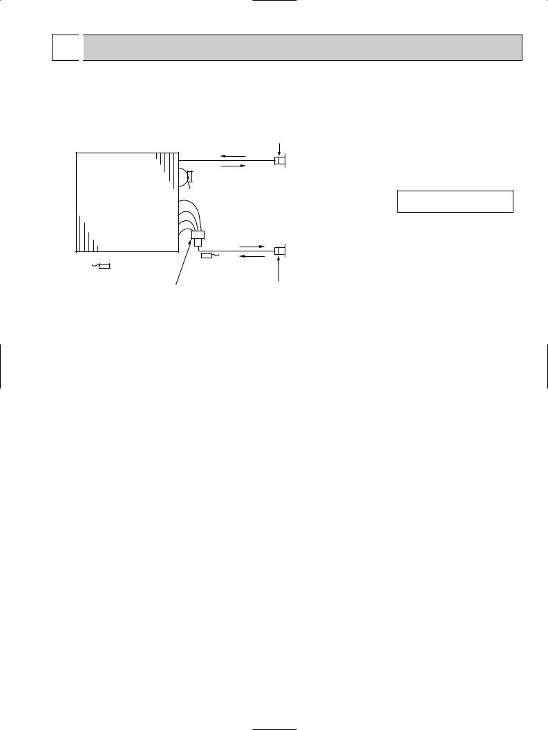
 REFRIGERANT SYSTEM DIAGRAM
PLA-A12AA PLA-A18AA PLA-A24AA PLA-A30AA PLA-A36AA PLA-A42AA PLA-A12AA1 PLA-A18AA1 PLA-A24AA1 PLA-A30AA1 PLA-A36AA1 PLA-A42AA1
Strainer (#50)
Heat exchanger
Refrigerant GAS pipe connection (Flare)
Thermistor TH5
(Cond./ Eva. temperature)
 Refrigerant flow in cooling
 Refrigerant flow in heating
Refrigerant LIQUID pipe connection
(Flare)
Thermistor TH2 Thermistor TH1 Pipe temperature (Liquid) (Room temperature)
Strainer (#50)
Distributor
with strainer (#50)
13

10 
 TROUBLESHOOTING
10-1. TROUBLESHOOTING
<Error code display by self-diagnosis and actions to be taken for service (summary)>
Present and past error codes are logged and displayed on the wired remote controller or controller board of outdoor unit. Actions to be taken for service and the inferior phenomenon reoccurrence at field are summarized in the table below. Check the contents below before investigating details.
Unit conditions at service |
Error code |
Actions to be taken for service (summary) |
|
|
|
|
|
|
Displayed |
Judge what is wrong and take a corrective action |
|
|
according to “SELF-DIAGNOSIS ACTION TABLE” (10-3). |
|
|
|
|
|
|
The inferior phenomenon is |
|
|
|
reoccurring. |
|
Identify the cause of the inferior phenomenon and take |
|
|
|
|
|
|
Not displayed |
a corrective action according to “TROUBLESHOOTING |
|
|
|
BY INFERIOR PHENOMENA ” (10-4). |
|
|
|
|
|
|
|
1Consider the temporary defects such as the work of |
|
|
|
protection devices in the refrigerant circuit including |
|
|
|
compressor, poor connection of wiring, noise and etc. |
|
|
|
Re-check the symptom, and check the installation |
|
|
|
environment, refrigerant amount, weather when the |
|
|
Logged |
inferior phenomenon occurred, and wiring related. |
|
|
2Reset error code logs and restart the unit after finishing |
|
|
|
|
|
|
|
|
service. |
|
|
|
3There is no abnormality in electrical components, |
|
The inferior phenomenon is |
|
controller boards, and remote controller. |
|
|
|
|
|
not reoccurring. |
|
1Recheck the abnormal symptom. |
|
|
|
|
|
|
|
2Identify the cause of the inferior phenomenon and take |
|
|
|
a corrective action according to “TROUBLESHOOTING |
|
|
Not logged |
BY INFERIOR PHENOMENA ” (10-4). |
|
|
3Continue to operate unit for the time being if the cause |
|
|
|
|
is not ascertained. |
|
|
|
4There is no abnormality in electrical components, |
|
|
|
controller boards, remote controller etc. |
|
|
|
|
|
14
 Loading...