


Mitsubishi Electronics PL18FK21, PL30FK21, PL24FK21, PL42FK21, PL36FK31 User Manual
...PL12FK1
PL18FK21
PL24FK21
PL30FK21
PL36FK31
PL42FK21
CONTENTS
1.TECHNICAL CHANGE ··················································································OC194- 2
2.FEATURES ····································································································OC194- 3
3.PART NAME AND FUNCTIONS ····································································OC194- 4
4.SPECIFICATIONS ··························································································OC194- 6
5.DATA ··············································································································OC194- 8
6.OUTLINES AND DIMENSIONS ····································································OC194-17
7.REFRIGERANT SYSTEM DIAGRAM ····························································OC194-19
8.WIRING DIAGRAM ························································································OC194-20
9.OPERATION FLOW-CHART··········································································OC194-22
10.MICROPROCESSOR CONTROL ··································································OC194-25
11.TROUBLESHOOTING ····················································································OC194-36
12.4-WAY AIR FLOW SYSTEM ········································································OC194-43
13.SYSTEM CONTROL ······················································································OC194-50
14.DISASSEMBLY PROCEDURE ······································································OC194-55
15.PARTS LIST ··································································································OC194-57
16.OPTIONAL PARTS ························································································OC194-63
OC194-1
1 |
|
|
TECHNICAL CHANGE |
|
||||||
|
|
|
|
|
|
|
|
|||
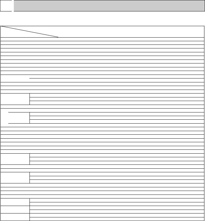
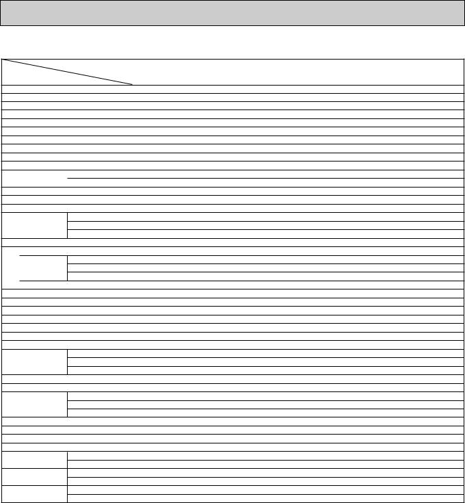
Differences with OC001 which is a basic service manual. |
|
|||||||||
|
|
|
|
|
|
|
|
|||
|
|
|
|
Change points |
|
FK2 |
FK21 |
|||
|
|
|
|
|
|
|
|
|
|
|
|
|
|
|
Appearances |
|
4-3/4 o 4-3/4 o 5/8 |
5-1/8 o 4-3/4 o 3/4 |
|||
Remote |
|
|
SW17 |
|
No.9 |
Switch for temperature unit |
Canceled |
|||
Dip switch |
|
|
No.0 |
Switch for louvers |
Canceled |
|||||
|
controller |
|
|
|
||||||
|
|
|
SW18 |
|
— |
Addition of "Mode selector" |
||||
|
|
|
|
|
|
|
||||
|
|
|
|
|
|
SW1 |
|
No.10 |
OFF |
ON |
|
|
|
|
|
|
|
|
|
|
|
|
|
|
|
Dip switch |
|
SW5 |
|
No.3 |
Control change of the normal and twin |
Addition of "Not yet used" |
Indoor controller |
|
|
|
|
|
|||||
|
|
No.4 |
Change of the unit No.1 and No.2 |
Addition of "LOSSNAY interlocked or not" |
||||||
|
|
|
|
|||||||
|
|
|
|
|
|
|
|
|
|
|
|
|
|
|
|
|
SW6 |
|
— |
Addition of "Mode selector" |
|
|
|
|
|
|
|
|
|
|||
|
|
|
|
Connector for LOSSNAY interlocked |
— |
Addition of "CN2L" |
||||
|
|
|
|
|
|
|
|
|||
Optional parts |
|
Program timer |
|
PAC–SK65PT |
PAC–SC32PTA |
|||||
OC194-2
2 
 FEATURES
|
|
SWING |
|
|
TIMER OFF TIMER |
CLOCK AUTO AUTO |
FAN |
|
|
FAN CHECK SET TEMP. |
START STOP |
FILTER |
||
SPEED |
||||
|
|
AUTO |
CHECK MODE |
|
|
|
RETURN |
TEST RUN
Remote controller
|
Unit |
|
Models |
Cooling capacity |
SEER |
PL12FK1 |
12,300 Btu/h |
10.4 |
PL18FK21 |
18,400 Btu/h |
10.2 |
PL24FK21 |
23,600 Btu/h |
10.0 |
PL30FK21 |
31,000 Btu/h |
10.4 |
PL36FK31 |
36,100 Btu/h |
10.0 |
PL42FK21 |
42,500 Btu/h |
10.0 |
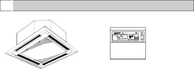
1.SPACE-SAVING CENTRALLY LOCATED CEILING RECESSED INSTALLATION
2.4-WAY AIR FLOW SYSTEM
This series allows you to select from 2, 3, and 4 way air flow directions according to your requirement. As a result, you get superb flexibility in choosing a configuration that gives you maximum cooling efficiency in a neat and unobstructive installation.
3. STABLE COOLING EVEN AT OUTDOOR TEMPERATURES AS LOW AS 0-F MAKES
YEARROUND AIR-CONDITIONING POSSIBLE. WIND BAFFLE REQUIRED.
The microprocessor automatically adjusts fan speed in accordance with outdoor temperature to maintain the coolant at an even condensing temperature. The result is smooth, efficient cooling even when temperatures outdoors drop as low as 0-F. This makes the unit ideal for a wide range of specialized cooling needs, such as rooms with many office machines or computers and areas subject to strong sunlight.
4.ADVANCED MICROPROCESSOR CONTROL
(1)Easy to use Microprocessor (remote controller)
1)Ultra-Thin Remote Controller
The streamlined, wide controller is designed to blend with any kind of interior and the adoption of a sophisticated microprocessor allows you to carry out a wide range of operations easily.
2)Attractive Liquid Crystal Display (LCD)
Units operation mode, set temperature, room temperature, timer setting, fan speed, and air flow direction are displayed on the remote controller with the easily understood visual Liquid Crystal Display (LCD).
3)Convenient 24-Hour ON-OFF Timer
The timer allows Mr.SLIM to be switched on or off automatically at the time is shown on the LCD.
4)Self-Diagnostic Feature Indicates Faults Instantly
In the rare case when a problem occurs, the unit stops operating and the set temperature indicator changes to the selfdiagnostic indicator, indicating the location of the fault.
If the check switch is pressed twice, the unit stops operating and the check mode is initiated. The cause of the most recent problem stored in the memory is displayed on the LCD. This is extremely useful for maintenance purposes.
5)Useful Memory Feature for Storing Instructions
The previous set value is memorized so that constant temperature control can be obtained. This is convenient when, for example, a power failure occurs.
(2)Non-polar Two-Wire Remote Controller Cables
The non-polar, two-wire type remote controller cable is slim, installation is simple and trouble-free. Remote controller wire can be extended up to 550 yards.
OC194-3

3 
 PART NAMES AND FUNCTIONS
Remote controller
Once the controls are set, the same operation mode can be repeated by simply pressing the ON / OFF button.
Remote controller operation buttons
TIMER ON/OFF button
This switches between continuous operation and the timer operation.
CLOCK/TIMER button
This sets or switches the current time,start time and stop time.
OPERATION MODE button
Press this button to switch the cooling, electronic dry (Dehumidify),fan modes.
SET TEMPERATURE button
This sets the room temperature. The temperature setting can be performed in 2-F units.
Setting range :
Cooling 65-F to 87-F
FAN SPEED button
This sets the fan speed.
DRY COOL |
|
|
SWING |
F |
TIMER OFF TIMER CLOCK AUTO AUTO |
|
|
||
FAN |
CHECK SET TEMP. |
START STOP FAN |
|
|
|
|
SPEED |
AUTO |
|
|
|
|
RETURN |
|
MODE |
TIMER ON/OFF CLOCK/TIMER FAN SPEED |
AIR DISCHARGE FILTER |
||
|
|
|
|
AIR SWEEP CHECK |
|
SET TEMP. |
TIMER SET |
|
TEST RUN |
REMOTE CONTROLLER
PAR-JC240KUS
ON/OFF button
This switches between the operation and stop modes each time it is press. The lamp on this button lights during operation.
AIR DISCHARGE button
This adjusts the vertical angle of the ventilation.
FILTER button
This resets the filter service indication display.
AIR SWEEP button
This switches the horizontal fan motion (Swing louver) ON and OFF.
(This button does not operate in this models.)
CHECK-TEST RUN button
Only press this button to perform an inspection check or test operation. Do not use it for normal operation.
OC194-4

Remote controller display
CENTRALLY CONTROLLED display
This indicates when the unit is controlled by optional features such as central control type remote controller.
TIMER display
This indicates when the continuous operation and time operation modes are set.
It also display the time for the timer operation at the same time as when it is set.
OPERATION MODE display
This indicates the operation mode.
CHECK display
This indicates when a malfunction has occurred in the unit which should be checked.
CLOCK display
The current time , start time and stop time can be displayed in ten second intervals by pressing the time switch button. The start time or stop time is always displayed during the timer operation.
In this display example on the bottom left, a condition where all display lamps light is shown for explanation purposes although this differs from actual operation.
AIR DISCHARGE display
This displays the air direction.
FAN SPEED display
The selected fan speed is displayed.
DRY COOL |
|
|
SWING |
F |
TIMER OFF TIMER CLOCK AUTO AUTO |
|
|
||
FAN |
CHECK SET TEMP. |
START STOP FAN |
|
|
|
|
SPEED |
AUTO |
|
|
|
|
RETURN |
|
MODE |
TIMER ON/OFF CLOCK/TIMER FAN SPEED |
AIR DISCHARGE FILTER |
||
|
|
|
|
AIR SWEEP CHECK |
|
SET TEMP. |
TIMER SET |
|
TEST RUN |
REMOTE CONTROLLER |
|
|
|
|
PAR-JC240KUS |
|
|
|
|
F display |
display |
This displays the selected setting |
This lamp lights when electricity is |
temperature. |
supplied to the unit. |


 F display
The temperature of the return air is displayed during operation. The display range is 47°F to 97°F. The display flashes 47°F when the actual temperature is less than 47°F and flashes 97°F when the actual temperature is greater than 97°F.
Operation lamp
This lamp lights during operation, goes off when the unit stops and flashes when a malfunction occurs.
CHECK MODE
display
TEST RUN
This display lights in the check mode or when a test operation is performed.
FILTER display
This lamp lights when the filter needs to be cleaned.
Caution |
|
● Only the |
display lights when the unit is stopped and power supplied to the unit. |
● When power is turned ON for the first time the (CENTRAL CTRL) display appears to go off momentarily but this is not a malfunction. ● When the control remote control unit, which is sold separately, is used the ON-OFF button,OPERATION MODE button and SET
TEMP. button do not operate.
●“NOT AVAILABLE” is displayed when the AIR SWEEP button are pressed. (AIR SWEEP function is not provided for PL series.)
OC194-5
4 
 SPECIFICATIONS
MODELS : PL12FK1, PL18/24FK21
|
|
|
|
|
|
|
|
Model |
|
PL12FK1 |
|
|
PL18FK21 |
|
|||
Item |
|
|
|
|
|
|
|
|
|
|
|
||||||
|
|
|
|
|
|
|
|
|
|
|
|
|
|
|
|||
|
|
|
|
*1 |
Btu/h |
|
|
|
|
|
|
|
|||||
Capacity |
|
|
|
|
|
|
18,400 |
|
|
||||||||
|
|
|
|
|
|
|
|
|
|
|
112,300 |
|
|
|
|
|
|
Power Consumption |
|
|
|
|
kW |
|
1.23 |
|
|
|
1.88 |
|
|
||||
EER |
|
|
|
|
*1 |
|
|
|
10.0 |
|
|
|
9.8 |
|
|
||
SEER |
|
|
|
*1 |
|
|
|
10.4 |
|
|
|
10.2 |
|
|
|||
INDOOR UNIT MODELS |
|
|
|
|
|
|
|
|
PL18FK2 |
1 |
|
||||||
|
|
|
|
|
|
|
|
|
|
|
PL12FK1 |
|
|
|
|
||
External finish |
|
|
|
|
|
|
|
|
Galvanized sheets with gray heat insulation |
||||||||
Power supply |
|
|
V,phase,Hz |
|
|
|
|
|
115 , 1 , 60 |
||||||||
|
|
|
|
|
|
|
|
|
|
||||||||
Max.fuse size (time delay) |
|
|
A |
|
15 |
|
|
|
15 |
|
|
||||||
Min.ampacity |
|
|
|
|
A |
|
2.0 |
|
|
|
2.0 |
|
|
||||
Fan motor |
|
|
|
F.L.A. |
|
0.75 |
|
|
|
0.85 |
|
|
|||||
|
|
|
|
|
Dry |
|
CFM |
|
|
|
|
|
680-460 |
|
|||
|
|
|
|
|
|
|
|
|
|
|
570-540 |
|
|
|
|||
Airflow |
Hi-Lo |
Wet |
|
CFM |
|
|
|
|
|
650-440 |
|
||||||
|
|
|
|
|
|
|
|
|
|
|
|
||||||
|
|
|
|
|
|
|
|
|
420-400 |
|
|
|
|||||
Moisture removal |
|
|
|
Pints/h |
|
3.8 |
|
|
|
5.3 |
|
|
|||||
Sound level Hi-Lo |
|
|
|
|
dB |
|
43-35 |
|
|
45-38 |
|
|
|||||
Cond. drain pipe O.D. |
|
|
|
|
in. |
|
1-1/4 |
|
|
1-1/4 |
|
|
|||||
|
|
|
|
|
W |
|
|
in. |
|
|
|
|
|
32-1/4 |
|
|
|
Dimensions |
D |
|
|
in. |
|
|
|
|
|
32-1/4 |
|
|
|||||
|
|
|
|
|
H |
|
|
in. |
|
|
|
|
|
10-1/8 |
|
|
|
Weight |
|
|
|
|
|
|
60 |
|
|
|
64 |
|
|
||||
|
|
|
External finish |
|
|
|
|
|
|
|
|
|
|
Munsell 0.70Y 8.59/0.97 |
|
||
|
GRILLE |
|
|
|
H |
|
|
in. |
|
|
|
|
2-3/8 |
|
|
||
INDOOR |
|
|
|
|
|
|
|
|
|
|
|
|
|||||
|
|
|
|
|
W |
|
|
in. |
|
|
|
|
|
36-5/8 |
|
|
|
|
|
|
Dimensions |
D |
|
|
in. |
|
|
|
|
|
36-5/8 |
|
|
||
|
|
|
|
|
|
|
|
|
|
|
|
|
|
|
|
|
|
|
|
|
Weight |
|
|
|
|
|
|
|
|
|
|
22 |
|
|
|
OUTDOOR UNIT MODELS |
|
|
|
|
PU12EK |
|
|
PU18EK1 |
|
||||||||
External finish |
|
|
|
|
|
|
|
|
|
|
Munsell 5Y 7/1 |
||||||
Sound level |
|
|
|
dB(A) |
|
50 |
|
|
|
53 |
|
|
|||||
Power supply |
|
|
V, phase, Hz |
|
|
|
|
|
208-230, 1, 60 |
||||||||
Max. fuse size (time delay) |
|
|
A |
|
15 |
|
|
|
20 |
|
|
||||||
Min. ampacity |
|
|
|
|
A |
|
11 |
|
|
|
16 |
|
|
||||
Fan motor |
|
|
|
F.L.A. |
|
0.65 |
|
|
|
0.75 |
|
|
|||||
|
|
|
|
|
Model (type) |
|
|
|
RH167NAB |
|
|
RH247NAB |
|
||||
Compressor |
|
|
|
R.L.A. |
|
8.9 |
|
|
|
12 |
|
|
|||||
|
|
|
|
|
|
|
|
L.R.A. |
|
29 |
|
|
|
37 |
|
|
|
Crankcase heater |
|
|
|
A(W) |
|
0.11/0.12 (23/28) |
|
|
0.11/0.12 (23/28) |
|
|||||||
Refrigerant control |
|
|
|
|
|
|
|
|
|
|
Capillary tube |
||||||
|
|
|
|
|
W |
|
|
in. |
|
|
|
|
|
34-1/4 |
|
|
|
Dimensions |
D |
|
|
in. |
|
|
|
|
|
11-5/8 |
|
|
|||||
|
|
|
|
|
H |
|
|
in. |
|
25-5/8 |
|
|
|
33-1/2 |
|
|
|
Weight |
|
|
|
|
lb |
|
105 |
|
|
|
154 |
|
|
||||
REMOTE CONTROLLER |
|
|
|
|
|
|
|
|
With indoor unit |
||||||||
Control voltage (by bulit-in. transformer) |
|
|
indoor unit - remote controller : DC12V, Indoor unit - outdoor unit |
||||||||||||||
REFRIGERANT PIPING |
|
|
|
|
|
|
|
|
|
Not supplied (optional parts) |
|||||||
Pipe size |
Liquid |
|
in. |
|
3/8 |
|
|
|
3/8 |
|
|
||||||
Gas |
|
in. |
|
5/8 |
|
|
|
5/8 |
|
|
|||||||
|
|
|
|
|
|
|
|
|
|
|
|
||||||
Connection method |
Indoors |
|
|
|
|
|
|
|
Flared |
|
|
||||||
Outdoors |
|
|
|
|
|
|
|
Flared |
|
|
|||||||
|
|
|
|
|
|
|
|
|
|
|
|
|
|
||||
Between the indoor |
Height difference |
ft |
|
130 |
|
|
|
130 |
|
|
|||||||
& outdoor units |
Piping length |
|
ft |
|
130 |
|
|
130 |
|
|
|||||||
NOTES : *1.Rating conditions —indoor : 80°FDB,67°FWB outdoor : 95°FDB,75°FWB.
PL24FK21
23,600
2.48
9.5
10.0
PL24FK21
15
2.0
1.1
750-550
660-480
6.8
47-39
1-1/4
64
PU24EK1
55
20
16 0.65+0.65
NH33NBD 11.5
54 0.16/0.17 (33/39)
49-9/16
207
: DC12V
3/8 5/8
164
164
Operating range
|
|
|
Indoor intake air temperature |
Outdoor intake air temperature |
|
|
|
|
|
|
|
Cooling |
Maximum |
|
95°FDB,71°FWB |
115°FDB |
|
Minimum |
|
67°FDB,57°FWB |
0°FDB* |
||
|
|
|
|||
* In |
case of the wind baffle is installed. |
|
|
||
|
|
|
|
||
|
|
|
|
|
|
(In case of the wind baffle is not installed, the minimum temperature will be 23°FDB.)
OC194-6
MODELS : PL30FK21, PL36FK31, PL42FK21
|
|
|
|
|
|
|
|
Model |
|
PL30FK21 |
|
PL36FK31 |
|
|||
Item |
|
|
|
|
|
|
|
|
|
|
||||||
|
|
|
|
|
|
|
|
|
|
|
|
|
|
|||
|
|
|
|
*1 |
Btu/h |
|
|
|
|
|
|
|||||
Capacity |
|
|
|
31,000 |
|
36,100 |
|
|
||||||||
Power Consumption |
|
|
|
|
kW |
|
3.10 |
|
|
3.76 |
|
|
||||
EER |
|
|
|
|
*1 |
|
|
|
10.0 |
|
|
9.6 |
|
|
||
SEER |
|
|
|
*1 |
|
|
|
10.4 |
|
|
10.0 |
|
|
|||
INDOOR UNIT MODELS |
|
|
|
|
|
|
|
PL36FK3 |
1 |
|
||||||
|
|
|
|
|
|
|
|
|
|
|
PL30FK21 |
|
|
|
||
External finish |
|
|
|
|
|
|
|
|
Galvanized sheets with gray heat insulation |
|||||||
Power supply |
|
|
V,phase,Hz |
|
|
|
|
115 , 1 , 60 |
||||||||
|
|
|
|
|
|
|
|
|
||||||||
Max.fuse size (time delay) |
|
|
A |
|
15 |
|
|
15 |
|
|
||||||
Min.ampacity |
|
|
|
|
A |
|
2.0 |
|
|
2.0 |
|
|
||||
Fan motor |
|
|
|
F.L.A. |
|
1.0+1.0 |
|
1.0+1.0 |
|
|
||||||
|
|
|
|
|
Dry |
|
CFM |
|
|
|
|
1,170-850 |
|
|||
Airflow |
Hi-Lo |
|
|
|
|
|
|
1,170-850 |
|
|
||||||
Wet |
|
CFM |
|
|
|
|
1,090-790 |
|
||||||||
|
|
|
|
|
|
|
|
|
1,090-790 |
|
|
|||||
Moisture removal |
|
|
|
Pints/h |
|
9.6 |
|
|
10.9 |
|
|
|||||
Sound level Hi-Lo |
|
|
|
|
dB |
|
49-41 |
|
49-41 |
|
|
|||||
Cond. drain pipe O.D. |
|
|
|
|
in. |
|
1-1/4 |
|
1-1/4 |
|
|
|||||
|
|
|
|
|
W |
|
|
in. |
|
|
|
|
52-3/4 |
|
|
|
Dimensions |
D |
|
|
in. |
|
|
|
|
32-1/4 |
|
|
|||||
|
|
|
|
|
H |
|
|
in. |
|
|
|
|
10-1/8 |
|
|
|
Weight |
|
|
|
|
|
|
99 |
|
|
99 |
|
|
||||
|
|
|
External finish |
|
|
|
|
|
|
|
|
|
Munsell 0.70Y 8.59/0.97 |
|
||
|
GRILLE |
|
|
|
H |
|
|
in. |
|
|
|
2-3/8 |
|
|
||
INDOOR |
|
|
|
|
|
|
|
|
|
|
|
|||||
|
|
|
|
|
W |
|
|
in. |
|
|
|
|
57-1/8 |
|
|
|
|
|
|
Dimensions |
D |
|
|
in. |
|
|
|
|
36-5/8 |
|
|
||
|
|
|
|
|
|
|
|
|
|
|
|
|
|
|
|
|
|
|
|
Weight |
|
|
|
|
|
|
|
|
|
35 |
|
|
|
OUTDOOR UNIT MODELS |
|
|
|
|
PU30EK1 |
|
PU36EK1 |
|
||||||||
External finish |
|
|
|
|
|
|
|
|
|
Munsell 5Y 7/1 |
||||||
Sound level |
|
|
|
dB(A) |
|
55 |
|
|
55 |
|
|
|||||
Power supply |
|
|
V, phase, Hz |
|
|
|
|
208-230, 1, 60 |
||||||||
Max. fuse size (time delay) |
|
|
A |
|
30 |
|
|
30 |
|
|
||||||
Min. ampacity |
|
|
|
|
A |
|
20 |
|
|
22 |
|
|
||||
Fan motor |
|
|
|
F.L.A. |
|
0.65-0.65 |
|
0.75+0.75 |
|
|||||||
|
|
|
|
|
Model (type) |
|
|
|
NH41NAD |
|
NH47NAD |
|
||||
Compressor |
|
|
|
R.L.A. |
|
14.0 |
|
|
17.5 |
|
|
|||||
|
|
|
|
|
|
|
|
L.R.A. |
|
73 |
|
|
87 |
|
|
|
Crankcase heater |
|
|
|
A(W) |
|
0.16/0.17 (33/39) |
|
0.16/0.17 (33/39) |
|
|||||||
Refrigerant control |
|
|
|
|
|
|
|
|
|
Capillary tube |
||||||
|
|
|
|
|
W |
|
|
in. |
|
34-1/4 |
|
|
38-3/16 |
|
|
|
Dimensions |
D |
|
|
in. |
|
11-5/8 |
|
|
13-9/16 |
|
|
|||||
|
|
|
|
|
H |
|
|
in. |
|
|
|
|
49-9/19 |
|
|
|
Weight |
|
|
|
|
lb |
|
208 |
|
|
154 |
|
|
||||
REMOTE CONTROLLER |
|
|
|
|
|
|
|
With indoor unit |
||||||||
Control voltage (by bulit-in. transformer) |
|
|
indoor unit - remote controller : DC12V, Indoor unit - outdoor unit |
|||||||||||||
REFRIGERANT PIPING |
|
|
|
|
|
|
|
|
Not supplied (optional parts) |
|||||||
Pipe size |
Liquid |
|
in. |
|
1/2 |
|
|
1/2 |
|
|
||||||
Gas |
|
in. |
|
3/4 |
|
|
3/4 |
|
|
|||||||
|
|
|
|
|
|
|
|
|
|
|
||||||
Connection method |
Indoors |
|
|
|
|
|
|
Flared |
|
|
||||||
Outdoors |
|
|
|
|
|
|
Flared |
|
|
|||||||
|
|
|
|
|
|
|
|
|
|
|
|
|
||||
Between the indoor |
Height difference |
ft |
|
164 |
|
|
164 |
|
|
|||||||
& outdoor units |
Piping length |
|
ft |
|
164 |
|
|
164 |
|
|
||||||
NOTES : *1.Rating conditions —indoor : 80°FDB,67°FWB outdoor : 95°FDB,75°FWB.
PL42FK21
42,500
4.40
9.7
10.0
PL42FK21
15
3.0
1.2+1.2
1,270-920
1,200-870
12.6
49-42
1-1/4
101
PU42EK2
56
40
27 0.8+0.8
NH569NXA
20
105 0.16/0.17 (33/39)
38-3/16
13-9/16
260
: DC12V
1/2 3/4
164
164
Operating range
|
|
|
Indoor intake air temperature |
Outdoor intake air temperature |
|
|
|
|
|
|
|
Cooling |
Maximum |
|
95°FDB,71°FWB |
115°FDB |
|
Minimum |
|
67°FDB,57°FWB |
0°FDB* |
||
|
|
|
|||
* In |
case of the wind baffle is installed. |
|
|
||
|
|
|
|
||
|
|
|
|
|
|
(In case of the wind baffle is not installed, the minimum temperature will be 23°FDB.)
OC194-7

5 
 DATA
DATA
MODELS : PL12FK1, PL18/24/30FK21, PL36FK31, PL42FK21
1.PERFORMANCE DATA
1)COOLING CAPACITY
|
|
Indoor air |
|
|
|
|
|
|
Outdoor intake air DB temperature(°F) |
|
|
|
|
|
||||||
|
|
|
|
|
|
|
|
|
|
|
|
|
|
|
|
|
|
|
|
|
Models |
|
Airflow |
|
IWB |
|
75 |
|
|
85 |
|
|
95 |
|
|
105 |
|
|
115 |
|
|
|
|
(CFM) |
|
|
|
|
|
|
|
|
|
|
|
|
|
|
|
|
|
|
|
|
|
(°F) |
TC |
SHC |
TPC |
TC |
SHC |
TPC |
TC |
SHC |
TPC |
TC |
SHC |
TPC |
TC |
SHC |
TPC |
||
|
|
B.F |
|
|||||||||||||||||
|
|
|
|
|||||||||||||||||
|
|
|
|
|
|
|
|
|
|
|
|
|
|
|
|
|
|
|
|
|
|
|
|
|
|
71 |
14.3 |
7.1 |
1.06 |
13.8 |
6.9 |
1.16 |
13.2 |
6.8 |
1.27 |
12.6 |
6.6 |
1.38 |
11.9 |
6.4 |
1.50 |
|
|
420 |
|
|
|
|
|
|
|
|
|
|
|
|
|
|
|
|
|
|
PL12FK1 |
|
|
|
67 |
13.2 |
8.4 |
1.03 |
12.8 |
8.2 |
1.12 |
12.3 |
8.0 |
1.23 |
11.8 |
7.8 |
1.34 |
11.2 |
7.6 |
1.46 |
|
0.27 |
|
|
||||||||||||||||||
|
|
|
|
|
|
|
|
|
|
|
|
|
|
|
|
|
|
|
||
|
63 |
12.1 |
9.3 |
0.99 |
11.8 |
9.1 |
1.08 |
11.4 |
9.0 |
1.18 |
11.1 |
8.8 |
1.29 |
10.4 |
8.4 |
1.40 |
||||
|
|
|
|
|
||||||||||||||||
|
|
|
|
|
|
|
|
|
|
|
|
|
|
|
|
|
|
|
|
|
|
|
|
|
|
71 |
21.2 |
14.6 |
1.64 |
20.6 |
13.6 |
1.77 |
19.6 |
12.5 |
1.93 |
18.7 |
11.6 |
2.10 |
17.9 |
10.6 |
2.23 |
PL18FK21 |
|
650 |
|
|
|
|
|
|
|
|
|
|
|
|
|
|
|
|
|
|
|
|
67 |
19.8 |
16.0 |
1.60 |
19.1 |
15.1 |
1.73 |
18.4 |
14.0 |
1.88 |
17.5 |
12.8 |
2.03 |
16.5 |
11.7 |
2.17 |
|||
0.17 |
|
|
||||||||||||||||||
|
|
|
|
|
|
|
|
|
|
|
|
|
|
|
|
|
|
|
||
|
|
63 |
18.5 |
17.2 |
1.56 |
17.9 |
16.1 |
1.70 |
17.1 |
15.0 |
1.83 |
16.3 |
13.9 |
1.98 |
15.3 |
12.7 |
2.12 |
|||
|
|
|
|
|
||||||||||||||||
|
|
|
|
|
|
|
|
|
|
|
|
|
|
|
|
|
|
|
|
|
|
|
|
|
|
71 |
27.4 |
17.8 |
2.15 |
26.5 |
16.7 |
2.36 |
25.3 |
15.2 |
2.57 |
24.0 |
13.8 |
2.77 |
22.8 |
12.5 |
3.00 |
PL24FK21 |
|
660 |
|
|
|
|
|
|
|
|
|
|
|
|
|
|
|
|
|
|
|
|
67 |
25.6 |
19.5 |
2.10 |
24.7 |
18.0 |
2.30 |
23.6 |
16.8 |
2.48 |
22.6 |
15.4 |
2.69 |
21.4 |
13.9 |
2.90 |
|||
0.13 |
|
|
||||||||||||||||||
|
|
|
|
|
|
|
|
|
|
|
|
|
|
|
|
|
|
|
||
|
|
63 |
23.8 |
20.5 |
2.05 |
22.9 |
19.0 |
2.24 |
22.1 |
18.1 |
2.43 |
21.0 |
16.6 |
2.62 |
20.0 |
15.2 |
2.81 |
|||
|
|
|
|
|
||||||||||||||||
|
|
|
|
|
|
|
|
|
|
|
|
|
|
|
|
|
|
|
|
|
|
|
|
|
|
71 |
35..8 |
19.4 |
2.65 |
34.5 |
19.1 |
2.88 |
33.5 |
18.8 |
3.17 |
31.4 |
18.5 |
3.44 |
29.6 |
18.0 |
3.76 |
PL30FK21 |
|
1090 |
|
|
|
|
|
|
|
|
|
|
|
|
|
|
|
|
|
|
|
|
67 |
33.2 |
22.6 |
2.59 |
31.9 |
22.1 |
2.81 |
31.0 |
21.6 |
3.10 |
28.8 |
20.9 |
3.35 |
27.4 |
20.4 |
3.63 |
|||
|
0.15 |
|
|
|||||||||||||||||
|
|
|
|
|
|
|
|
|
|
|
|
|
|
|
|
|
|
|
||
|
|
|
|
|
63 |
30.9 |
25.1 |
2.53 |
29.8 |
24.6 |
2.75 |
29.0 |
23.9 |
3.02 |
26.9 |
23.1 |
3.28 |
25.6 |
22.5 |
3.55 |
|
|
|
|
|
|
|
|
|
|
|
|
|
|
|
|
|
|
|
|
|
|
|
|
|
|
71 |
41.7 |
27.1 |
3.22 |
40.3 |
25.4 |
3.52 |
38.6 |
23.5 |
3.85 |
36.8 |
22.1 |
4.22 |
34.9 |
20.2 |
4.56 |
PL36FK31 |
|
1090 |
|
|
|
|
|
|
|
|
|
|
|
|
|
|
|
|
|
|
|
|
67 |
38.9 |
29.6 |
3.15 |
37.5 |
28.1 |
3.44 |
36.1 |
26.4 |
3.76 |
34.5 |
24.5 |
4.10 |
32.5 |
22.4 |
4.42 |
|||
0.15 |
|
|
||||||||||||||||||
|
|
|
|
|
|
|
|
|
|
|
|
|
|
|
|
|
|
|
||
|
|
63 |
36.4 |
32.0 |
3.08 |
35.1 |
30.2 |
3.36 |
33.5 |
28.1 |
3.67 |
31.9 |
26.2 |
4.00 |
30.2 |
24.2 |
4.30 |
|||
|
|
|
|
|
||||||||||||||||
|
|
|
|
|
|
|
|
|
|
|
|
|
|
|
|
|
|
|
|
|
|
|
|
|
|
71 |
49.6 |
32.3 |
3.95 |
47.8 |
30.0 |
4.25 |
45.8 |
28.0 |
4.60 |
43.5 |
25.7 |
4.85 |
41.2 |
23.1 |
5.20 |
PL42FK21 |
|
1200 |
|
|
|
|
|
|
|
|
|
|
|
|
|
|
|
|
|
|
|
|
67 |
46.1 |
35.0 |
3.88 |
44.3 |
32.8 |
4.10 |
42.5 |
30.6 |
4.40 |
40.2 |
28.2 |
4.65 |
37.7 |
25.3 |
4.95 |
|||
|
0.14 |
|
|
|||||||||||||||||
|
|
|
|
|
|
|
|
|
|
|
|
|
|
|
|
|
|
|
||
|
|
|
|
|
63 |
42.8 |
37.2 |
3.80 |
41.1 |
34.9 |
4.00 |
39.3 |
32.6 |
4.28 |
37.1 |
29.7 |
4.45 |
34.8 |
27.1 |
4.75 |
|
|
|
|
|
|
|
|
|
|
|
|
|
|
|
|
|
|
|
|
|
Notes 1. B.F. : Bypass Factor, IWB : Intake air wet-bulb temperature
TC : Total Capacity (x103 Btu/h), SHC : Sensible Heat Capacity (x103 Btu/h)
TPC : Total Power Consumption (kW)
2.SHC is based on 80°F of indoor intake air DB temperature.
2)COOLING CAPACITY CORRECTIONS
|
|
|
Refrigerant piping length (one way) |
|
|
|
|
|
|
|
|||||
MODEL |
|
|
|
|
|
|
|
|
|
|
|
|
|
|
|
|
25ft (std) |
40ft |
55ft |
70ft |
85ft |
100ft |
115ft |
|
130ft |
150ft |
164ft |
||||
|
|
|
|
|
|
|
|
|
|
|
|
|
|
|
|
PL12FK1 |
1.0 |
0.992 |
0.983 |
0.978 |
0.966 |
0.959 |
0.950 |
|
0.945 |
|
|
|
|
|
|
PL18FK21 |
|
|
|
|
|
||||||||||
|
|
|
|
|
|
|
|
|
|
|
|
|
|
|
|
|
1.0 |
0.981 |
0.968 |
0.952 |
0.940 |
0.925 |
0.913 |
|
0.900 |
0.886 |
0.874 |
||||
PL24FK21 |
|
||||||||||||||
|
|
|
|
|
|
|
|
|
|
|
|
|
|
|
|
PL30FK21 |
1.0 |
0.981 |
0.968 |
0.952 |
0.940 |
0.925 |
0.913 |
|
0.900 |
0.886 |
0.874 |
||||
|
|
|
|
|
|
|
|
|
|
|
|
|
|
|
|
PL36FK31 |
1.0 |
0.981 |
0.968 |
0.952 |
0.940 |
0.925 |
0.913 |
0.900 |
0.886 |
0.874 |
|||||
|
|
|
|
|
|
|
|
|
|
|
|
|
|
|
|
PL42FK21 |
1.0 |
0.975 |
0.955 |
0.935 |
0.918 |
0.900 |
0.884 |
|
0.869 |
0.855 |
0.840 |
||||
|
|
|
|
|
|
|
|
|
|
|
|
|
|
|
|
OC194-8
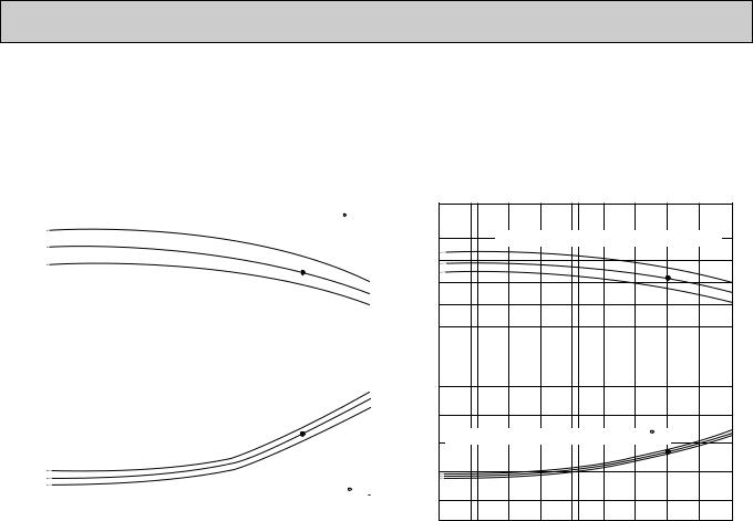
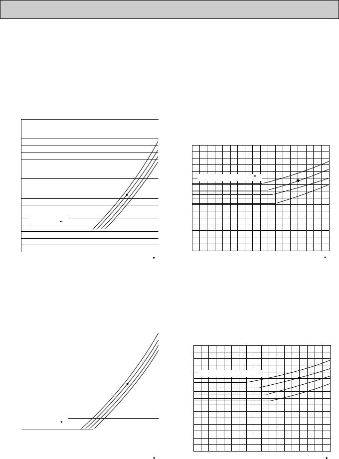
2. PERFORMANCE CURVE
NOTES : A point on the curve shows the reference point.
PL12FK1 COOLING CAPACITY |
PL18FK21 COOLING CAPACITY |
Total power consumption (kW) Total capacity (x103 Btu/h)
18 |
|
|
|
|
|
|
|
|
|
|
|
|
|
|
|
|
|
|
|
SHF=0.77 |
Btu/h) |
||||
|
|
|
|
|
|
|
|
|
|
|
|
|
|
|
|
|
|
|
|
|
|
|
|
||
|
|
|
|
|
|
|
|
Indoor intake air WB temperature ( F) |
|
|
|
||||||||||||||
|
|
|
|
|
|
|
|
|
|
|
|
|
|
|
|
|
|
|
|
|
|
|
|
|
(x103 |
18 |
|
|
|
|
|
|
|
|
|
|
|
|
|
|
|
|
|
|
|
|
|
|
|
71 |
capacity |
|
|
|
|
|
|
|
|
|
|
|
|
|
|
|
|
|
|
|
|
|
|
|
|
||
|
|
|
|
|
|
|
|
|
|
|
|
|
|
|
|
|
|
|
|
|
|
|
|
67 |
|
|
|
|
|
|
|
|
|
|
|
|
|
|
|
|
|
|
|
|
|
|
|
|
|
63 |
Total |
|
|
|
|
|
|
|
|
|
|
|
|
|
|
|
|
|
|
|
|
|
|
|
|
|
|
6 |
|
|
|
|
|
|
|
|
|
|
|
|
|
|
|
|
|
|
|
|
|
|
|
|
(kW) |
|
|
|
|
|
|
|
|
|
|
|
|
|
|
|
|
|
|
|
|
|
|
|
|
||
1.6 |
|
|
|
|
|
|
|
|
|
|
|
|
|
|
|
|
|
|
|
|
|
|
|
71 |
|
|
|
|
|
|
|
|
|
|
|
|
|
|
|
|
|
|
|
|
|
|
|
|
consumption |
||
|
|
|
|
|
|
|
|
|
|
|
|
|
|
|
|
|
|
|
|
|
|
|
|
||
1.4 |
|
|
|
|
|
|
|
|
|
|
|
|
|
|
|
|
|
|
|
|
|
|
|
67 |
|
|
|
|
|
|
|
|
|
|
|
|
|
|
|
|
|
|
|
|
|
|
|
|
63 |
|
|
|
|
|
|
|
|
|
|
|
|
|
|
|
|
|
|
|
|
|
|
|
|
|
|
||
1.2 |
|
|
|
|
|
|
|
|
|
|
|
|
|
|
|
|
|
|
|
|
|
|
|
|
power |
|
|
|
|
|
|
|
|
|
|
|
|
|
|
|
|
|
|
|
|
|
|
|
|
||
1.0 |
|
|
|
|
|
|
|
|
|
|
|
|
|
|
|
|
|
|
|
|
|
|
|
|
|
|
|
|
|
|
|
|
|
|
|
|
|
|
|
|
|
|
|
|
|
|
|
|
|
|
|
|
|
|
|
|
|
|
|
|
|
|
|
|
|
|
|
|
|
|
|
||||||
0.8 |
|
|
|
|
|
|
|
|
Indoor intake air WB temperature ( F) |
|
Total |
||||||||||||||
|
|
|
|
|
|
|
|
|
|||||||||||||||||
|
|
|
|
|
|
|
|
|
|
|
|
|
|
|
|
|
|
|
|
|
|
|
|
||
0 |
|
|
|
|
|
|
|
|
|
|
|
|
|
|
|
|
|
|
|
|
|
|
|
|
|
32 |
35 |
45 |
55 |
65(67) |
75 |
85 |
95 |
105 |
115 |
|
|||||||||||||||
Outdoor intake air DB temperature ( F)
F)
24
21
18
15
12
3.0
2.5
2.0
1.5
1.0
0
SHF=0.76
Indoor intake air WB temperature ( F)
F)
71
67
63
|
71 |
Indoor intake air WB temperature ( F) |
67 |
|
63 |
32 35 |
45 |
55 |
65(67) |
75 |
85 |
95 |
105 |
115 |
Outdoor intake air DB temperature ( F)
F)
OC194-9

NOTES : A point on the curve shows the reference point.
PL24FK21 COOLING CAPACITY |
PL30FK21 COOLING CAPACITY |
Total power consumption (kW) Total capacity (x103 Btu/h)
36 |
|
|
|
|
|
|
|
|
|
|
|
|
|
|
|
|
|
|
SHF=0.71 |
Btu/h)3 |
||||
|
|
|
|
|
|
|
|
|
|
|
|
|
|
|
|
|
|
|
|
|
|
|
(x10 |
|
30 |
|
|
|
|
|
|
|
|
|
|
|
|
|
|
|
|
|
|
|
|
|
|
|
|
|
|
Indoor intake air WB temperature ( F) |
|
|
|
|
||||||||||||||||||
24 |
|
|
|
|
|
|
|
|
|
|
|
|
|
|
|
|
|
|
|
|
|
|
71 |
capacity |
|
|
|
|
|
|
|
|
|
|
|
|
|
|
|
|
|
|
|
|
|
|
Total |
||
|
|
|
|
|
|
|
|
|
|
|
|
|
|
|
|
|
|
|
|
|
|
|
||
|
|
|
|
|
|
|
|
|
|
|
|
|
|
|
|
|
|
|
|
|
|
|
67 |
|
18 |
|
|
|
|
|
|
|
|
|
|
|
|
|
|
|
|
|
|
|
|
|
|
63 |
|
|
|
|
|
|
|
|
|
|
|
|
|
|
|
|
|
|
|
|
|
|
|
|
(kW) |
|
3.5 |
|
|
|
|
|
|
|
|
|
|
|
|
|
|
|
|
|
|
|
|
|
|
|
|
|
|
|
|
|
|
|
|
|
|
|
|
|
|
|
|
|
|
|
|
|
|
71 |
consumption |
|
|
|
|
|
|
|
|
|
|
|
|
|
|
|
|
|
|
|
|
|
|
|
|||
3.0 |
|
|
|
|
|
|
|
|
|
|
|
|
|
|
|
|
|
|
|
|
|
|
||
|
|
|
|
|
|
|
|
|
|
|
|
|
|
|
|
|
|
|
|
|
|
|
67 |
|
2.5 |
|
Indoor intake air WB temperature ( F) |
|
|
|
|
|
63 |
|
|||||||||||||||
|
|
|
|
|
|
|
|
|
|
|
|
|
|
|
|
|
|
|
|
|
|
|
power |
|
|
|
|
|
|
|
|
|
|
|
|
|
|
|
|
|
|
|
|
|
|
|
|
||
2.0 |
|
|
|
|
|
|
|
|
|
|
|
|
|
|
|
|
|
|
|
|
|
|
|
|
|
|
|
|
|
|
|
|
|
|
|
|
|
|
|
|
|
|
|
|
|
|
|
Total |
|
1.5 |
|
|
|
|
|
|
|
|
|
|
|
|
|
|
|
|
|
|
|
|
|
|
|
|
|
|
|
|
|
|
|
|
|
|
|
|
|
|
|
|
|
|
|
|
|
|
|
|
|
|
|
|
|
|
|
|
|
|
|
|
|
|
|
|
|
|
|
|
|
|
|
|
|
|
23 |
32 35 |
45 |
55 |
65(67) |
75 |
85 |
95 |
105 |
115 |
|
||||||||||||||
Outdoor intake air DB temperature ( F)
F)
SHF=0.76
42
Indoor intake air WB temperature ( F)
F)
36
30
71
67
63
24
4.0 |
|
71 |
|
|
|
||
3.5 |
|
67 |
|
Indoor intake air WB temperature ( F) |
63 |
||
|
|||
|
|
||
3.0 |
|
|
|
2.5 |
|
|
23 32 35 45 55 65(67) 75 85 95 105 115
Outdoor intake air DB temperature ( F)
F)
Total power consumption (kW) Total capacity (x103 Btu/h)
48
42
36
30
4.5
4.0
3.5
3.0
2.5
PL36FK31 COOLING CAPACITY |
PL42FK21 COOLING CAPACITY |
|
SHF=0.73 |
Btu/h) |
Indoor intake air WB temperature ( F) |
|
|
|
71 |
capacity (x103 |
|
Total |
|
|
67 |
|
|
|
|
|
63 |
|
Indoor intake air WB temperature ( F)
F)
71 |
(kW) |
|
67 |
consumptionpowerTotal |
|
63 |
||
|
54
48
42
36
2.0
1.5
SHF=0.72 Indoor intake air WB temperature ( F)
F)
71
67
63
|
71 |
|
Indoor intake air WB temperature ( F) |
67 |
|
63 |
||
|
23 |
32 35 |
45 |
55 |
65(67) |
75 |
85 |
95 |
105 |
115 |
23 |
32 35 |
45 |
55 |
65(67) |
75 |
85 |
95 |
105 |
115 |
|
|
Outdoor intake air DB temperature ( F) |
|
|
|
Outdoor intake air DB temperature ( F) |
|
||||||||||||
OC194-10
3. CONDENSING PRESSURE AND SUCTION PRESSURE
Data is based on the condition of indoor humidity 50%. Air flow should be set at HI.
A point on the curve shows the reference point.
<PL12FK1>
COOLING MODE
(psi.G) |
|
|
|
|
|
|
|
|
|
|
|
|
|
|
|
|
|
|
|
|
|
|
|
350 |
|
|
|
|
|
|
|
|
|
|
|
|
|
|
|
|
|
|
|
|
|
|
340 |
|
|
|
|
|
|
|
|
|
|
|
|
|
|
|
|
|
|
|
|
|
|
|
|
|
|
|
|
|
|
|
|
|
|
|
|
|
|
|
|
|
|
|
|
|
330 |
|
|
|
|
|
|
|
|
|
|
|
|
|
|
|
|
|
|
|
|
86 |
|
|
|
|
|
|
|
|
|
|
|
|
|
|
|
|
|
|
|
|
|
||
|
320 |
|
|
|
|
|
|
|
|
|
|
|
|
|
|
|
|
|
|
|
|
|
|
|
|
|
|
|
|
|
|
|
|
|
|
|
|
|
|
|
|
|
|
80 |
|
|
|
|
|
|
|
|
|
|
|
|
|
|
|
|
|
|
|
|
|
|
||
|
310 |
|
|
|
|
|
|
|
|
|
|
|
|
|
|
|
|
|
|
|
|
75 |
|
|
|
|
|
|
|
|
|
|
|
|
|
|
|
|
|
|
|
|
|
||
|
300 |
|
|
|
|
|
|
|
|
|
|
|
|
|
|
|
|
|
|
|
|
70 |
|
|
|
|
|
|
|
|
|
|
|
|
|
|
|
|
|
|
|
|
|
||
|
290 |
|
|
|
|
|
|
|
|
|
|
|
|
|
|
|
|
|
|
|
|
|
|
|
|
|
|
|
|
|
|
|
|
|
|
|
|
|
|
|
|
|
|
|
|
pressure |
280 |
|
|
|
|
|
|
|
|
|
|
|
|
|
|
|
|
|
|
|
|
|
|
|
|
|
|
|
|
|
|
|
|
|
|
|
|
|
|
|
|
|
|
||
270 |
|
|
|
|
|
|
|
|
|
|
|
|
|
|
|
|
|
|
|
|
|
|
|
|
|
|
|
|
|
|
|
|
|
|
|
|
|
|
|
|
|
|
|
|
|
|
260 |
|
|
|
|
|
|
|
|
|
|
|
|
|
|
|
|
|
|
|
|
|
|
|
|
|
|
|
|
|
|
|
|
|
|
|
|
|
|
|
|
|
|
|
|
Condensing |
250 |
|
|
|
|
|
|
|
|
|
|
|
|
|
|
|
|
|
|
|
|
|
|
|
|
|
|
|
|
|
|
|
|
|
|
|
|
|
|
|
|
|
|
||
210 |
|
|
|
|
|
|
|
|
|
|
|
|
|
|
|
|
|
|
|
|
|
|
|
240 |
|
|
|
|
|
|
|
|
|
|
|
|
|
|
|
|
|
|
|
|
|
|
230 |
|
|
|
|
|
|
|
|
|
|
|
|
|
|
|
|
|
|
|
|
|
|
220 |
|
|
|
|
|
|
|
|
|
|
|
|
|
|
|
|
|
|
|
|
|
|
|
|
|
|
|
|
|
|
|
|
|
|
|
|
|
|
|
|
|
|
|
|
|
|
|
|
|
|
|
|
|
|
|
|
|
|
|
|
|
|
|
|
|
|
|
|
|
|
|
|
|
|
|
|
|
|
|
|
|
|
|
|
|
|
|
|
|
|
|
200 |
|
|
|
|
Indoor DB |
|
|
|
|
|
|
|
|
|
|
|
|
|
|||
|
|
|
|
|
|
|
|
|
|
|
|
|
|
|
|
|
|
|||||
|
190 |
|
|
temperature( F) |
|
|
|
|
|
|
|
|
|
|
|
|
|
|||||
|
|
|
|
|
|
|
|
|
|
|
|
|
|
|
|
|
|
|
|
|
|
|
|
180 |
|
|
|
|
|
|
|
|
|
|
|
|
|
|
|
|
|
|
|
|
|
|
|
|
|
|
|
|
|
|
|
|
|
|
|
|
|
|
|
|
|
|
|
|
|
170 |
|
|
|
|
|
|
|
|
|
|
|
|
|
|
|
|
|
|
|
|
|
|
|
|
|
|
|
|
|
|
|
|
|
|
|
|
|
|
|
|
|
|
|
|
|
160 |
|
|
|
|
|
|
|
|
|
|
|
|
|
|
|
|
|
|
|
|
|
|
|
|
|
|
|
|
|
|
|
|
|
|
|
|
|
|
|
|
|
|
|
|
|
150 |
|
|
|
|
|
|
|
|
|
|
|
|
|
|
|
|
|
|
|
|
|
|
30 |
40 |
50 |
|
60 |
70 |
80 |
90 |
100 |
110 |
|
|||||||||||
|
|
|
|
|||||||||||||||||||
|
|
|
|
|
|
|
Outdoor ambient temperature |
|
|
DB( F) |
||||||||||||
(psi.G) 100
90
80
pressure |
|
|
70 |
||
|
||
|
|
|
|
60 |
|
Suction |
|
|
50 |
||
|
||
|
|
|
|
40 |
|
|
|
|
|
30 |
|
|
|
|
|
20 |
|
86 |
|
80 |
Indoor DB temperature( F) |
75 |
|
|
|
70 |
30 |
40 |
50 |
60 |
70 |
80 |
90 |
100 |
110 |
|
|
Outdoor ambient temperature |
|
DB( F) |
||||
<PL18FK21>
COOLING MODE
(psi.G) |
|
|
|
|
|
|
|
|
|
|
|
|
|
|
|
|
|
|
|
|
|
|
|
|
|
|
350 |
|
|
|
|
|
|
|
|
|
|
|
|
|
|
|
|
|
|
|
|
|
|
|
|
|
|
|
|
|
|
|
|
|
|
|
|
|
|
|
|
|
|
|
|
|
|
|
|
|
|
|
340 |
|
|
|
|
|
|
|
|
|
|
|
|
|
|
|
|
|
|
|
|
86 |
|
|
|
|
|
|
|
|
|
|
|
|
|
|
|
|
|
|
|
|
|
|
|
|
|
|
|
||
|
330 |
|
|
|
|
|
|
|
|
|
|
|
|
|
|
|
|
|
|
|
|
(psi.G) |
|
||
|
|
|
|
|
|
|
|
|
|
|
|
|
|
|
|
|
|
|
|
|
|||||
|
320 |
|
|
|
|
|
|
|
|
|
|
|
|
|
|
|
|
|
|
|
|
80 |
|
||
|
|
|
|
|
|
|
|
|
|
|
|
|
|
|
|
|
|
|
|
|
|||||
|
310 |
|
|
|
|
|
|
|
|
|
|
|
|
|
|
|
|
|
|
|
|
75 |
|
100 |
|
|
|
|
|
|
|
|
|
|
|
|
|
|
|
|
|
|
|
|
|
|
|
||||
|
300 |
|
|
|
|
|
|
|
|
|
|
|
|
|
|
|
|
|
|
|
70 |
|
|
|
|
|
|
|
|
|
|
|
|
|
|
|
|
|
|
|
|
|
|
|
|
|
|
||||
|
290 |
|
|
|
|
|
|
|
|
|
|
|
|
|
|
|
|
|
|
|
|
|
|
90 |
|
|
|
|
|
|
|
|
|
|
|
|
|
|
|
|
|
|
|
|
|
|
|
|
|
||
Condensingpressure |
280 |
|
|
|
|
|
|
|
|
|
|
|
|
|
|
|
|
|
|
|
|
|
pressureSuction |
|
|
|
|
|
Indoor |
DB |
|
|
|
|
|
|
|
|
|
|
|
|
|
|
|
||||||
200 |
|
|
|
|
|
|
|
|
|
|
|
|
|
|
|
|
|
|
|||||||
|
270 |
|
|
|
|
|
|
|
|
|
|
|
|
|
|
|
|
|
|
|
|
|
|
80 |
|
|
260 |
|
|
|
|
|
|
|
|
|
|
|
|
|
|
|
|
|
|
|
|
|
|
|
|
|
250 |
|
|
|
|
|
|
|
|
|
|
|
|
|
|
|
|
|
|
|
|
|
|
70 |
|
|
240 |
|
|
|
|
|
|
|
|
|
|
|
|
|
|
|
|
|
|
|
|
|
|
|
|
|
230 |
|
|
|
|
|
|
|
|
|
|
|
|
|
|
|
|
|
|
|
|
|
|
60 |
|
|
|
|
|
|
|
|
|
|
|
|
|
|
|
|
|
|
|
|
|
|
|
|
|
||
|
220 |
|
|
|
|
|
|
|
|
|
|
|
|
|
|
|
|
|
|
|
|
|
|
|
|
|
210 |
|
|
|
|
|
|
|
|
|
|
|
|
|
|
|
|
|
|
|
|
|
|
50 |
|
|
|
|
temperature( F) |
|
|
|
|
|
|
|
|
|
|
|
|
|
|
|
|
40 |
|
||||
|
190 |
|
|
|
|
|
|
|
|
|
|
|
|
|
|
|
|
|
|
||||||
|
|
|
|
|
|
|
|
|
|
|
|
|
|
|
|
|
|
|
|||||||
|
180 |
|
|
|
|
|
|
|
|
|
|
|
|
|
|
|
|
|
|
|
|
|
|
|
|
|
170 |
|
|
|
|
|
|
|
|
|
|
|
|
|
|
|
|
|
|
|
|
|
|
30 |
|
|
|
|
|
|
|
|
|
|
|
|
|
|
|
|
|
|
|
|
|
|
|
|
|
||
|
160 |
|
|
|
|
|
|
|
|
|
|
|
|
|
|
|
|
|
|
|
|
|
|
|
|
|
150 |
|
|
|
|
|
|
|
|
|
|
|
|
|
|
|
|
|
|
|
|
|
|
20 |
|
|
30 |
40 |
50 |
60 |
70 |
80 |
90 |
100 |
110 |
|
|
|
|
||||||||||||
|
|
|
|
|
|
|
|||||||||||||||||||
|
|
|
|
|
|
Outdoor ambient temperature |
|
|
DB( F) |
|
|
|
|||||||||||||
|
86 |
|
80 |
Indoor DB temperature( F) |
75 |
|
70 |
30 |
40 |
50 |
60 |
70 |
80 |
90 |
100 |
110 |
|
|
Outdoor ambient temperature |
|
DB( F) |
||||
OC194-11
Data is based on the condition of indoor humidity 50%. Air flow should be set at HI.
A point on the curve shows the reference point.
<PL24FK21> COOLING MODE
(psi.G) |
|
|
|
|
|
|
|
|
|
|
|
|
|
|
|
|
|
|
|
|
|
|
|
350 |
|
|
|
|
|
|
|
|
|
|
|
|
|
|
|
|
|
|
|
|
|
|
|
|
|
|
|
|
|
|
|
|
|
|
|
|
|
|
|
|
|
|
|
|
|
340 |
|
|
|
|
|
|
|
|
|
|
|
|
|
|
|
|
|
|
|
|
|
|
|
|
|
|
|
|
|
|
|
|
|
|
|
|
|
|
|
|
|
|
|
|
|
330 |
|
|
|
|
|
|
|
|
|
|
|
|
|
|
|
|
|
|
|
|
|
|
|
|
|
|
|
|
|
|
|
|
|
|
|
|
|
|
|
|
|
|
|
|
|
320 |
|
|
|
|
|
|
|
|
|
|
|
|
|
|
|
|
|
|
|
|
86 |
|
310 |
|
|
|
|
|
|
|
|
|
|
|
|
|
|
|
|
|
|
|
|
|
|
|
|
|
|
|
|
|
|
|
|
|
|
|
|
|
|
|
|
|
|
80 |
|
|
300 |
|
|
|
|
|
|
|
|
|
|
|
|
|
|
|
|
|
|
|
|
|
|
|
|
|
|
|
|
|
|
|
|
|
|
|
|
|
|
|
|
|
|
75 |
|
|
290 |
|
|
|
|
|
|
|
|
|
|
|
|
|
|
|
|
|
|
|
|
|
|
|
|
|
|
|
|
|
|
|
|
|
|
|
|
|
|
|
|
|
|
70 |
|
pressure |
280 |
|
|
|
|
|
|
|
|
|
|
|
|
|
|
|
|
|
|
|
|
|
|
|
|
|
|
|
|
|
|
|
|
|
|
|
|
|
|
|
|
|
|
||
|
|
|
|
|
|
|
|
|
|
|
|
|
|
|
|
|
|
|
|
|
||
270 |
|
|
|
|
|
|
|
|
|
|
|
|
|
|
|
|
|
|
|
|
|
|
|
|
|
|
|
|
|
|
|
|
|
|
|
|
|
|
|
|
|
|
|
|
|
|
260 |
|
|
|
|
|
|
|
|
|
|
|
|
|
|
|
|
|
|
|
|
|
Condensing |
250 |
|
|
|
|
|
|
|
|
|
|
|
|
|
|
|
|
|
|
|
|
|
|
|
|
|
|
|
|
|
|
|
|
|
|
|
|
|
|
|
|
|
|
||
210 |
|
|
|
|
|
|
|
|
|
|
|
|
|
|
|
|
|
|
|
|
|
|
|
240 |
|
|
|
|
|
|
|
|
|
|
|
|
|
|
|
|
|
|
|
|
|
|
230 |
|
|
|
|
|
|
|
|
|
|
|
|
|
|
|
|
|
|
|
|
|
|
220 |
|
|
|
|
|
|
|
|
|
|
|
|
|
|
|
|
|
|
|
|
|
|
|
|
|
|
|
|
|
|
|
|
|
|
|
|
|
|
|
|
|
|
|
|
|
|
|
|
|
|
|
|
|
|
|
|
|
|
|
|
|
|
|
|
|
|
|
|
200 |
|
|
|
Indoor DB |
|
|
|
|
|
|
|
|
|
|
|
|
|
||||
|
190 |
|
temperature( F) |
|
|
|
|
|
|
|
|
|
|
|
|
|
|
|||||
|
|
|
|
|
|
|
|
|
|
|
|
|
|
|
|
|
|
|
|
|
|
|
|
180 |
|
|
|
|
|
|
|
|
|
|
|
|
|
|
|
|
|
|
|
|
|
|
170 |
|
|
|
|
|
|
|
|
|
|
|
|
|
|
|
|
|
|
|
|
|
|
160 |
|
|
|
|
|
|
|
|
|
|
|
|
|
|
|
|
|
|
|
|
|
|
150 |
|
|
|
|
|
|
|
|
|
|
|
|
|
|
|
|
|
|
|
|
|
|
30 |
40 |
50 |
|
|
60 |
70 |
80 |
90 |
100 |
110 |
|
||||||||||
|
|
|
|
|
||||||||||||||||||
|
|
|
|
|
|
Outdoor ambient temperature |
|
|
DB( F) |
|||||||||||||
(psi.G)
100
|
|
|
|
90 |
|
|
|
|
|
80 |
|
pressure |
|
|
70 |
||
|
||
|
|
|
|
60 |
|
Suction |
|
|
50 |
||
|
||
|
|
|
|
40 |
|
|
|
|
|
30 |
|
|
|
|
|
20 |
86
80
Indoor DB temperature( F) |
75 |
70
30 |
40 |
50 |
60 |
70 |
80 |
90 |
100 |
110 |
|
|
Outdoor ambient temperature |
|
DB( F) |
||||
<PL30FK21>
|
|
COOLING MODE |
|
|
|
|
|
|
|
|
|
|
|
||||||||
(psi.G) |
|
|
|
|
|
|
|
|
|
|
|
|
|
|
|
|
|
|
|
|
|
|
350 |
|
|
|
|
|
|
|
|
|
|
|
|
|
|
|
|
|
|
|
|
|
340 |
|
|
|
|
|
|
|
|
|
|
|
|
|
|
|
|
|
|
|
|
|
|
|
|
|
|
|
|
|
|
|
|
|
|
|
|
|
|
|
|
|
|
|
330 |
|
|
|
|
|
|
|
|
|
|
|
|
|
|
|
|
|
|
|
86 |
|
|
|
|
|
|
|
|
|
|
|
|
|
|
|
|
|
|
|
|
||
|
320 |
|
|
|
|
|
|
|
|
|
|
|
|
|
|
|
|
|
|
|
80 |
|
|
|
|
|
|
|
|
|
|
|
|
|
|
|
|
|
|
|
|
||
|
310 |
|
|
|
|
|
|
|
|
|
|
|
|
|
|
|
|
|
|
|
75 |
|
|
|
|
|
|
|
|
|
|
|
|
|
|
|
|
|
|
|
|
||
|
300 |
|
|
|
|
|
|
|
|
|
|
|
|
|
|
|
|
|
|
|
70 |
|
|
|
|
|
|
|
|
|
|
|
|
|
|
|
|
|
|
|
|
|
|
|
290 |
|
|
|
|
|
|
|
|
|
|
|
|
|
|
|
|
|
|
|
|
|
|
|
|
|
|
|
|
|
|
|
|
|
|
|
|
|
|
|
|
|
|
pressure |
280 |
|
|
|
|
|
|
|
|
|
|
|
|
|
|
|
|
|
|
|
|
|
|
|
|
|
|
|
|
|
|
|
|
|
|
|
|
|
|
|
|
||
270 |
|
|
|
|
|
|
|
|
|
|
|
|
|
|
|
|
|
|
|
|
|
|
|
|
|
|
|
|
|
|
|
|
|
|
|
|
|
|
|
|
|
|
|
|
260 |
|
|
|
|
|
|
|
|
|
|
|
|
|
|
|
|
|
|
|
|
|
|
|
|
|
|
|
|
|
|
|
|
|
|
|
|
|
|
|
|
|
|
Condensing |
250 |
|
|
|
|
|
|
|
|
|
|
|
|
|
|
|
|
|
|
|
|
|
|
|
|
|
|
|
|
|
|
|
|
|
|
|
|
|
|
|
|
||
210 |
|
|
|
|
|
|
|
|
|
|
|
|
|
|
|
|
|
|
|
|
|
|
240 |
|
|
|
|
|
|
|
|
|
|
|
|
|
|
|
|
|
|
|
|
|
230 |
|
|
|
|
|
|
|
|
|
|
|
|
|
|
|
|
|
|
|
|
|
220 |
|
|
|
|
|
|
|
|
|
|
|
|
|
|
|
|
|
|
|
|
|
|
|
|
|
|
|
|
|
|
|
|
|
|
|
|
|
|
|
|
|
|
|
|
|
|
|
|
|
|
|
|
|
|
|
|
|
|
|
|
|
|
|
|
|
|
|
|
|
|
|
|
|
|
|
|
|
|
|
|
|
|
|
|
|
|
|
200 |
|
|
|
Indoor DB |
|
|
|
|
|
|
|
|
|
|
|
|
|
|||
|
|
|
|
|
|
|
|
|
|
|
|
|
|
|
|
|
|||||
|
190 |
|
temperature( F) |
|
|
|
|
|
|
|
|
|
|
|
|
|
|
||||
|
|
|
|
|
|
|
|
|
|
|
|
|
|
|
|
|
|
|
|
|
|
|
180 |
|
|
|
|
|
|
|
|
|
|
|
|
|
|
|
|
|
|
|
|
|
|
|
|
|
|
|
|
|
|
|
|
|
|
|
|
|
|
|
|
|
|
|
170 |
|
|
|
|
|
|
|
|
|
|
|
|
|
|
|
|
|
|
|
|
|
|
|
|
|
|
|
|
|
|
|
|
|
|
|
|
|
|
|
|
|
|
|
160 |
|
|
|
|
|
|
|
|
|
|
|
|
|
|
|
|
|
|
|
|
|
|
|
|
|
|
|
|
|
|
|
|
|
|
|
|
|
|
|
|
|
|
|
150 |
|
|
|
|
|
|
|
|
|
|
|
|
|
|
|
|
|
|
|
|
|
30 |
40 |
50 |
|
60 |
70 |
80 |
90 |
100 |
110 |
|
||||||||||
|
|
|
|
||||||||||||||||||
|
|
|
|
|
|
Outdoor ambient temperature |
|
|
DB( F) |
||||||||||||
(psi.G)
100
|
|
|
|
90 |
|
|
|
|
|
80 |
|
pressure |
|
|
70 |
||
|
||
|
|
|
|
60 |
|
Suction |
|
|
50 |
||
|
||
|
|
|
|
40 |
|
|
|
|
|
30 |
|
|
|
|
|
20 |
86
80
Indoor DB temperature( F)
F)
75
70
30 |
40 |
50 |
60 |
70 |
80 |
90 |
100 |
110 |
|
|
Outdoor ambient temperature |
|
DB( F) |
||||
OC194-12
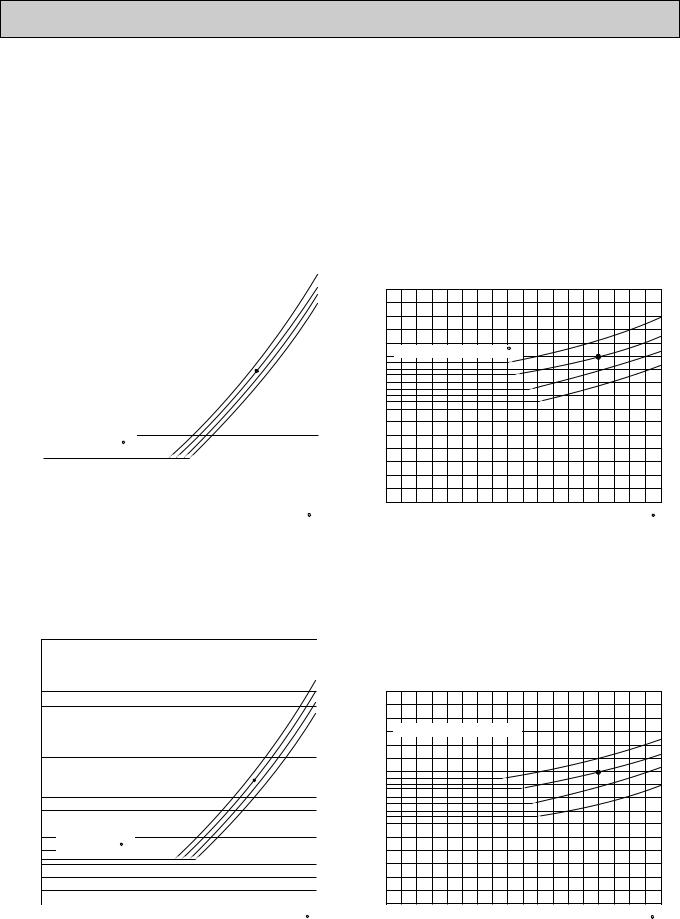
Data is based on the condition of indoor humidity 50%. Air flow should be set at HI.
A point on the curve shows the reference point.
<PL36FK31> COOLING MODE
(psi.G) |
|
|
|
|
|
|
|
|
|
|
|
|
|
|
|
|
|
|
|
|
|
|
350 |
|
|
|
|
|
|
|
|
|
|
|
|
|
|
|
|
|
|
|
|
|
340 |
|
|
|
|
|
|
|
|
|
|
|
|
|
|
|
|
|
|
|
|
|
|
|
|
|
|
|
|
|
|
|
|
|
|
|
|
|
|
|
|
|
|
|
330 |
|
|
|
|
|
|
|
|
|
|
|
|
|
|
|
|
|
|
|
86 |
|
|
|
|
|
|
|
|
|
|
|
|
|
|
|
|
|
|
|
|
||
|
320 |
|
|
|
|
|
|
|
|
|
|
|
|
|
|
|
|
|
|
|
|
|
|
|
|
|
|
|
|
|
|
|
|
|
|
|
|
|
|
|
|
80 |
|
|
310 |
|
|
|
|
|
|
|
|
|
|
|
|
|
|
|
|
|
|
|
|
|
|
|
|
|
|
|
|
|
|
|
|
|
|
|
|
|
|
|
|
75 |
|
|
|
|
|
|
|
|
|
|
|
|
|
|
|
|
|
|
|
|
|
||
|
300 |
|
|
|
|
|
|
|
|
|
|
|
|
|
|
|
|
|
|
|
70 |
|
|
|
|
|
|
|
|
|
|
|
|
|
|
|
|
|
|
|
|
||
|
290 |
|
|
|
|
|
|
|
|
|
|
|
|
|
|
|
|
|
|
|
|
|
|
|
|
|
|
|
|
|
|
|
|
|
|
|
|
|
|
|
|
|
|
pressure |
280 |
|
|
|
|
|
|
|
|
|
|
|
|
|
|
|
|
|
|
|
|
|
|
|
|
|
|
|
|
|
|
|
|
|
|
|
|
|
|
|
|
||
270 |
|
|
|
|
|
|
|
|
|
|
|
|
|
|
|
|
|
|
|
|
|
|
|
|
|
|
|
|
|
|
|
|
|
|
|
|
|
|
|
|
|
|
|
|
260 |
|
|
|
|
|
|
|
|
|
|
|
|
|
|
|
|
|
|
|
|
|
|
|
|
|
|
|
|
|
|
|
|
|
|
|
|
|
|
|
|
|
|
Condensing |
250 |
|
|
|
|
|
|
|
|
|
|
|
|
|
|
|
|
|
|
|
|
|
|
|
|
|
|
|
|
|
|
|
|
|
|
|
|
|
|
|
|
||
210 |
|
|
|
|
|
|
|
|
|
|
|
|
|
|
|
|
|
|
|
|
|
|
240 |
|
|
|
|
|
|
|
|
|
|
|
|
|
|
|
|
|
|
|
|
|
230 |
|
|
|
|
|
|
|
|
|
|
|
|
|
|
|
|
|
|
|
|
|
220 |
|
|
|
|
|
|
|
|
|
|
|
|
|
|
|
|
|
|
|
|
|
|
|
|
|
|
|
|
|
|
|
|
|
|
|
|
|
|
|
|
|
|
|
|
|
|
|
|
|
|
|
|
|
|
|
|
|
|
|
|
|
|
|
|
|
|
|
|
|
|
|
|
|
|
|
|
|
|
|
|
|
|
|
|
|
|
|
200 |
|
|
|
Indoor DB |
|
|
|
|
|
|
|
|
|
|
|
|
|
|||
|
|
|
|
|
|
|
|
|
|
|
|
|
|
|
|
|
|||||
|
190 |
|
temperature( F) |
|
|
|
|
|
|
|
|
|
|
|
|
|
|
||||
|
|
|
|
|
|
|
|
|
|
|
|
|
|
|
|
|
|
|
|
|
|
|
180 |
|
|
|
|
|
|
|
|
|
|
|
|
|
|
|
|
|
|
|
|
|
|
|
|
|
|
|
|
|
|
|
|
|
|
|
|
|
|
|
|
|
|
|
170 |
|
|
|
|
|
|
|
|
|
|
|
|
|
|
|
|
|
|
|
|
|
|
|
|
|
|
|
|
|
|
|
|
|
|
|
|
|
|
|
|
|
|
|
160 |
|
|
|
|
|
|
|
|
|
|
|
|
|
|
|
|
|
|
|
|
|
|
|
|
|
|
|
|
|
|
|
|
|
|
|
|
|
|
|
|
|
|
|
150 |
|
|
|
|
|
|
|
|
|
|
|
|
|
|
|
|
|
|
|
|
|
30 |
40 |
50 |
|
60 |
70 |
80 |
90 |
100 |
110 |
|
||||||||||
|
|
|
|
||||||||||||||||||
|
|
|
|
|
|
Outdoor ambient temperature |
|
|
DB( F) |
||||||||||||
(psi.G) 100
|
|
|
|
90 |
|
|
|
|
|
80 |
|
pressure |
|
|
70 |
||
|
||
|
|
|
|
60 |
|
Suction |
|
|
50 |
||
|
||
|
|
|
|
40 |
|
|
|
|
|
30 |
|
|
|
|
|
20 |
86
80
Indoor DB temperature( F) |
75 |
70
30 |
40 |
50 |
60 |
70 |
80 |
90 |
100 |
110 |
|
|
Outdoor ambient temperature |
|
DB( F) |
||||
<PL42FK21>
|
|
COOLING MODE |
|
|
|
|
|
|
|
|
|
|
|
||||||||
(psi.G) |
|
|
|
|
|
|
|
|
|
|
|
|
|
|
|
|
|
|
|
|
|
|
350 |
|
|
|
|
|
|
|
|
|
|
|
|
|
|
|
|
|
|
|
|
|
|
|
|
|
|
|
|
|
|
|
|
|
|
|
|
|
|
|
|
|
|
|
340 |
|
|
|
|
|
|
|
|
|
|
|
|
|
|
|
|
|
|
|
|
|
|
|
|
|
|
|
|
|
|
|
|
|
|
|
|
|
|
|
|
|
|
|
330 |
|
|
|
|
|
|
|
|
|
|
|
|
|
|
|
|
|
|
|
|
|
|
|
|
|
|
|
|
|
|
|
|
|
|
|
|
|
|
|
|
|
|
|
320 |
|
|
|
|
|
|
|
|
|
|
|
|
|
|
|
|
|
|
|
86 |
|
|
|
|
|
|
|
|
|
|
|
|
|
|
|
|
|
|
|
|
||
|
310 |
|
|
|
|
|
|
|
|
|
|
|
|
|
|
|
|
|
|
|
80 |
|
300 |
|
|
|
|
|
|
|
|
|
|
|
|
|
|
|
|
|
|
|
75 |
|
|
|
|
|
|
|
|
|
|
|
|
|
|
|
|
|
|
|
|
70 |
|
|
290 |
|
|
|
|
|
|
|
|
|
|
|
|
|
|
|
|
|
|
|
|
|
|
|
|
|
|
|
|
|
|
|
|
|
|
|
|
|
|
|
|
|
|
pressure |
280 |
|
|
|
|
|
|
|
|
|
|
|
|
|
|
|
|
|
|
|
|
|
|
|
|
|
|
|
|
|
|
|
|
|
|
|
|
|
|
|
|
||
270 |
|
|
|
|
|
|
|
|
|
|
|
|
|
|
|
|
|
|
|
|
|
|
|
|
|
|
|
|
|
|
|
|
|
|
|
|
|
|
|
|
|
|
|
|
260 |
|
|
|
|
|
|
|
|
|
|
|
|
|
|
|
|
|
|
|
|
Condensing |
250 |
|
|
|
|
|
|
|
|
|
|
|
|
|
|
|
|
|
|
|
|
|
|
|
|
|
|
|
|
|
|
|
|
|
|
|
|
|
|
|
|
||
210 |
|
|
|
|
|
|
|
|
|
|
|
|
|
|
|
|
|
|
|
|
|
|
240 |
|
|
|
|
|
|
|
|
|
|
|
|
|
|
|
|
|
|
|
|
|
230 |
|
|
|
|
|
|
|
|
|
|
|
|
|
|
|
|
|
|
|
|
|
220 |
|
|
|
|
|
|
|
|
|
|
|
|
|
|
|
|
|
|
|
|
|
|
|
|
|
|
|
|
|
|
|
|
|
|
|
|
|
|
|
|
|
|
|
|
|
|
|
|
|
|
|
|
|
|
|
|
|
|
|
|
|
|
|
|
|
200 |
|
|
|
Indoor DB |
|
|
|
|
|
|
|
|
|
|
|
|
|
|||
|
190 |
|
temperature( F) |
|
|
|
|
|
|
|
|
|
|
|
|
|
|
||||
|
|
|
|
|
|
|
|
|
|
|
|
|
|
|
|
|
|
|
|
|
|
|
180 |
|
|
|
|
|
|
|
|
|
|
|
|
|
|
|
|
|
|
|
|
|
170 |
|
|
|
|
|
|
|
|
|
|
|
|
|
|
|
|
|
|
|
|
|
160 |
|
|
|
|
|
|
|
|
|
|
|
|
|
|
|
|
|
|
|
|
|
150 |
|
|
|
|
|
|
|
|
|
|
|
|
|
|
|
|
|
|
|
|
|
30 |
40 |
50 |
|
60 |
70 |
80 |
90 |
100 |
110 |
|
||||||||||
|
|
|
|
||||||||||||||||||
|
|
|
|
|
|
Outdoor ambient temperature |
|
|
DB( F) |
||||||||||||
(psi.G) 100
90
80
pressure |
|
|
70 |
||
|
||
|
|
|
|
60 |
|
Suction |
|
|
50 |
||
|
||
|
|
|
|
40 |
|
|
|
|
|
30 |
|
|
|
|
|
20 |
Indoor DB temperature( F)
F)
86
80
75
70
30 |
40 |
50 |
60 |
70 |
80 |
90 |
100 |
110 |
|
|
Outdoor ambient temperature |
|
DB( F) |
||||
OC194-13

4. STANDARD OPERATION DATA
Total
Electrical circuit
Refrigerant circuit
Outdoor side Indoor side
|
|
Model |
|
|
PL12FK1 |
PL18FK21 |
PL24FK21 |
PL30FK21 |
PL36FK31 |
PL42FK21 |
||
|
|
Item |
|
Unit |
Cooling |
Cooling |
Cooling |
Cooling |
Cooling |
Cooling |
||
|
Capacity |
|
|
|
Btu / t |
12,300 |
18,400 |
23,600 |
31,000 |
36,100 |
42,500 |
|
|
|
|
|
|||||||||
|
|
|
|
|
|
|
|
|
|
|
|
|
|
SHF |
|
|
|
— |
0.77 |
0.76 |
0.71 |
0.76 |
0.73 |
0.72 |
|
|
|
|
|
|
|
|
|
|
|
|
|
|
|
Input |
|
|
|
kW |
1.23 |
1.88 |
2.48 |
3.1 |
3.76 |
4.40 |
|
|
INDOOR UNIT MODEL |
|
|
PL12FK1 |
PL18FK21 |
PL24FK21 |
PL30FK21 |
PL36FK31 |
PL42FK21 |
|||
|
|
|
|
|
|
|
|
|
|
|
|
|
|
Power supply (V, phase, Hz) |
|
|
115, 1, 60 |
115, 1, 60 |
115, 1, 60 |
115, 1, 60 |
115, 1, 60 |
115, 1, 60 |
|||
|
|
|
|
|
|
|
|
|
|
|
|
|
|
Input |
|
|
|
kW |
0.10 |
0.10 |
0.12 |
0.1+0.1 |
0.1+0.1 |
0.13+0.13 |
|
|
|
|
|
|
|
|
|
|
|
|
|
|
|
Fan current |
|
A |
0.75 |
0.85 |
1.06 |
0.9+0.9 |
0.9+0.9 |
1.15+1.15 |
|||
|
|
|
|
|
|
|
|
|
|
|
|
|
|
OUTDOOR UNIT MODEL |
|
|
PU12EK |
PU18EK1 |
PU24EK1 |
PU30EK1 |
PU36EK1 |
PU42EK21 |
|||
|
|
|
|
|
|
|
|
|
|
|
|
|
|
Power supply (V, phase, Hz) |
|
|
208/230, 1, 60 |
208/230, 1, 60 |
208/230, 1, 60 |
208/230, 1, 60 |
208/230, 1, 60 |
208/230, 1, 60 |
|||
|
|
|
|
|
|
|
|
|
|
|
|
|
|
Input |
|
|
|
kW |
1.13 |
1.78 |
2.36 |
2.90 |
3.56 |
4.14 |
|
|
|
|
|
|
|
|
|
|
|
|
|
|
|
Comp. current |
|
A |
8.9 |
12.0 |
11.5 |
14.0 |
15.9 |
20.4 |
|||
|
|
|
|
|
|
|
|
|
|
|
|
|
|
Fan current |
|
A |
0.75 |
0.75 |
0.65+0.65 |
0.65+0.65 |
0.75+0.75 |
0.8+0.8 |
|||
|
Condensing pressure |
|
psi•G |
246 |
252 |
236 |
237 |
249 |
236 |
|||
|
|
|
|
|
|
|
|
|
|
|
|
|
|
Suction pressure |
|
psi•G |
82 |
79 |
74 |
76 |
75 |
70 |
|||
|
|
|
|
|
|
|
|
|
|
|
|
|
|
Discharge temp. |
|
°F |
154 |
161 |
162 |
165 |
164 |
166 |
|||
|
|
|
|
|
|
|
|
|
|
|
|
|
|
Condensing temp. |
|
°F |
116 |
117 |
113 |
113 |
115 |
113 |
|||
|
|
|
|
|
|
|
|
|
|
|
|
|
|
Suction temp. |
|
°F |
50 |
51 |
45 |
47 |
46 |
44 |
|||
|
|
|
|
|
|
|
|
|
|
|
|
|
|
Ref. pipe length |
|
ft |
25 |
25 |
25 |
25 |
25 |
25 |
|||
|
|
|
|
|
|
|
|
|
|
|
|
|
|
Refrigerant charge |
|
— |
4 lbs 14oz |
5 lbs 8 oz |
9 lbs 15 oz |
10 lbs 2 oz |
10 lbs 9 oz |
12 lbs 9 oz |
|||
|
|
|
|
DB |
°F |
80 |
80 |
80 |
80 |
80 |
80 |
|
|
|
|
||||||||||
|
Intake air temperature |
|
|
|
|
|
|
|
|
|
|
|
|
WB |
°F |
67 |
67 |
67 |
67 |
67 |
67 |
||||
|
|
|
|
|||||||||
|
|
|
|
|
|
|
|
|
|
|
|
|
|
|
|
|
DB |
°F |
64 |
60 |
57 |
59 |
59 |
58 |
|
|
Discharge air temperature |
|
|
|
|
|
|
|
|
|
|
|
|
WB |
°F |
60 |
58 |
56 |
58 |
57 |
56 |
||||
|
|
|
|
|||||||||
|
|
|
|
|
|
|
|
|
|
|
|
|
|
Fan speed (High) |
|
rpm |
590 |
680 |
710 |
660 |
660 |
710 |
|||
|
|
|
|
|
|
|
|
|
|
|
|
|
|
Airflow (High) |
|
CFM |
420 |
650 |
660 |
1,090 |
1,090 |
1200 |
|||
|
|
|
|
DB |
°F |
95 |
95 |
95 |
95 |
95 |
95 |
|
|
Intake air temperature |
|
|
|
|
|
|
|
|
|
|
|
|
WB |
°F |
— |
— |
— |
— |
— |
— |
||||
|
|
|
||||||||||
|
|
|
|
|
|
|
|
|
|
|
|
|
|
Fan speed upper / lower |
|
rpm |
790 |
790 |
750 750 |
750 750 |
760 760 |
840 |
840 |
||
|
Airflow |
|
|
|
CFM |
1,590 |
1,590 |
3,170 |
3,170 |
3,350 |
3,530 |
|
|
|
|
|
|
|
|
|
|
|
|
|
|
5.OPERATING RANGE
1)POWER SUPPLY
|
Rating |
Allowable voltage |
|
|
|
|
|
|
|
Indoor unit |
115V 1 phase 60Hz |
Min. 103V |
— Max. 127V |
|
|
|
|
|
|
Outdoor unit |
208/230V 1 phase 60Hz |
Min. 198V |
— Max. 253V |
|
|
|
|
|
|
2) OPERATION
Intake air temperature |
Indoor |
|
|
Outdoor |
Function |
DB (°F) |
WB (°F) |
DB (°F) |
|
Condition |
WB (°F) |
|||
Standard temperature |
80 |
67 |
95 |
75 |
Maximum temperature |
95 |
71 |
115 |
75 |
Cooling |
67 |
57 |
0 |
|
Minimum temperature |
— |
|||
Maximum humidity |
80 |
75 |
80 |
75 |
OC194-14
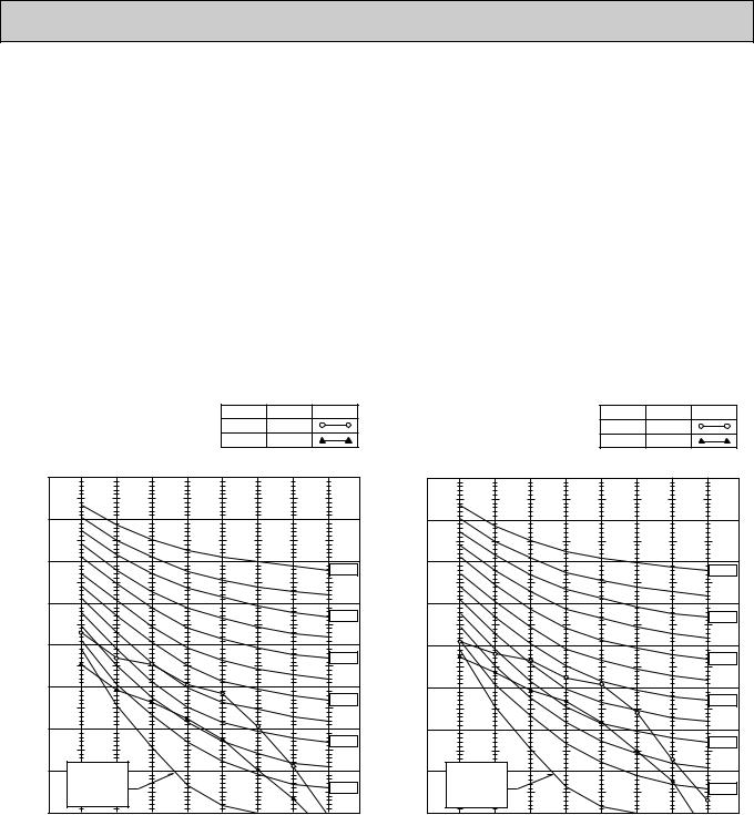
6.OUTLET AIR SPEED AND COVERAGE RANGE
|
|
|
|
|
PL12FK1 |
PL18FK21 |
PL24FK21 |
PL30FK21 |
PL36FK31 |
PL42FK21 |
|
|
|
|
|
|
|
|
|
|
|
|
|
|
|
|
|
|
|
|
|
|
|
||
Standard |
|
Airflow |
|
(CFM) |
570 |
680 |
750 |
1,170 |
1,170 |
1,270 |
|
|
|
|
|
|
|
|
|
|
|
||
|
Air speed |
(ft / sec.) |
9.5 |
11.3 |
12.5 |
10.5 |
10.5 |
11.4 |
|||
height |
|||||||||||
|
|
|
|
|
|
|
|
|
|||
Coverage range |
(ft) |
18 |
21 |
23 |
27 |
27 |
29 |
||||
|
|
||||||||||
|
|
|
|
|
|
|
|
|
|
|
|
•The air coverage range is the value up to the position where the air speed is 0.8ft/sec. when air is blown out horizontally from the unit at the High fan setting.
The coverage range should be used only as a general guideline since it varies according to the size of the room and furniture installed inside the room.
7. NOISE CRITERION CURVES
PL12FK1 |
|
|
|
NOTCH |
SPL(dB) |
LINE |
|||
|
|
|
|
|
|
|
Hi |
43 |
|
|
|
|
|
|
|
|
Lo |
35 |
|
|
90 |
|
|
|
|
|
|
|
|
BAR |
80 |
|
|
|
|
|
|
|
|
MICRO |
|
|
|
|
|
|
|
|
|
|
|
|
|
|
|
|
|
|
|
dB re 0.002 |
70 |
|
|
|
|
|
|
|
NC-70 |
|
|
|
|
|
|
|
|
||
60 |
|
|
|
|
|
|
|
|
|
LEVEL, |
|
|
|
|
|
|
|
|
|
|
|
|
|
|
|
|
|
NC-60 |
|
|
|
|
|
|
|
|
|
|
|
PRESSURE |
50 |
|
|
|
|
|
|
|
|
|
|
|
|
|
|
|
|
NC-50 |
|
40 |
|
|
|
|
|
|
|
|
|
SOUND |
|
|
|
|
|
|
|
|
|
|
|
|
|
|
|
|
|
NC-40 |
|
|
|
|
|
|
|
|
|
|
|
BAND |
30 |
|
|
|
|
|
|
|
|
|
|
|
|
|
|
|
NC-30 |
||
|
|
|
|
|
|
|
|
||
|
|
|
|
|
|
|
|
|
|
OCTAVE |
20 |
APPROXIMATE |
|
|
|
|
|
|
|
|
THRESHOLD OF |
|
|
|
|
|
|
||
|
HEARING FOR |
|
|
|
|
|
NC-20 |
||
|
|
CONTINUOUS |
|
|
|
|
|
||
|
|
|
|
|
|
|
|
||
|
|
NOISE |
|
|
|
|
|
|
|
|
10 |
63 |
125 |
250 |
500 |
1000 |
2000 |
4000 |
8000 |
|
|
||||||||
BAND CENTER FREQUENCIES, Hz
PL18FK21 |
|
|
|
NOTCH |
SPL(dB) |
LINE |
|||
|
|
|
|
|
|
|
Hi |
45 |
|
|
|
|
|
|
|
|
Lo |
38 |
|
|
90 |
|
|
|
|
|
|
|
|
BAR |
80 |
|
|
|
|
|
|
|
|
MICRO |
|
|
|
|
|
|
|
|
|
|
|
|
|
|
|
|
|
|
|
dB re 0.002 |
70 |
|
|
|
|
|
|
|
NC-70 |
|
|
|
|
|
|
|
|
||
60 |
|
|
|
|
|
|
|
|
|
LEVEL, |
|
|
|
|
|
|
|
|
|
|
|
|
|
|
|
|
|
NC-60 |
|
|
|
|
|
|
|
|
|
|
|
PRESSURE |
50 |
|
|
|
|
|
|
|
|
|
|
|
|
|
|
|
|
NC-50 |
|
40 |
|
|
|
|
|
|
|
|
|
SOUND |
|
|
|
|
|
|
|
|
|
|
|
|
|
|
|
|
|
NC-40 |
|
|
|
|
|
|
|
|
|
|
|
BAND |
30 |
|
|
|
|
|
|
|
|
|
|
|
|
|
|
|
|
NC-30 |
|
|
|
|
|
|
|
|
|
|
|
OCTAVE |
20 |
APPROXIMATE |
|
|
|
|
|
|
|
|
|
|
|
|
|
|
|
||
|
THRESHOLD OF |
|
|
|
|
|
|
||
|
HEARING FOR |
|
|
|
|
|
NC-20 |
||
|
|
CONTINUOUS |
|
|
|
|
|
||
|
|
|
|
|
|
|
|
||
|
|
NOISE |
|
|
|
|
|
|
|
|
10 |
63 |
125 |
250 |
500 |
1000 |
2000 |
4000 |
8000 |
|
|
||||||||
BAND CENTER FREQUENCIES, Hz
OC194-15

8. NOISE CRITERION CURVES
PL24FK21 |
|
|
|
NOTCH |
SPL(dB) |
LINE |
|||
|
|
|
|
|
|
|
Hi |
47 |
|
|
|
|
|
|
|
|
Lo |
39 |
|
|
90 |
|
|
|
|
|
|
|
|
BAR |
80 |
|
|
|
|
|
|
|
|
MICRO |
|
|
|
|
|
|
|
|
|
dB re 0.002 |
70 |
|
|
|
|
|
|
|
NC-70 |
|
|
|
|
|
|
|
|
||
60 |
|
|
|
|
|
|
|
|
|
LEVEL, |
|
|
|
|
|
|
|
|
|
|
|
|
|
|
|
|
|
NC-60 |
|
|
|
|
|
|
|
|
|
|
|
PRESSURE |
50 |
|
|
|
|
|
|
|
|
|
|
|
|
|
|
|
|
NC-50 |
|
40 |
|
|
|
|
|
|
|
|
|
SOUND |
|
|
|
|
|
|
|
|
|
|
|
|
|
|
|
|
|
NC-40 |
|
30 |
|
|
|
|
|
|
|
|
|
BAND |
|
|
|
|
|
|
|
|
|
|
|
|
|
|
|
|
|
NC-30 |
|
|
|
|
|
|
|
|
|
|
|
OCTAVE |
20 |
APPROXIMATE |
|
|
|
|
|
|
|
|
THRESHOLD OF |
|
|
|
|
|
|
||
|
HEARING FOR |
|
|
|
|
|
NC-20 |
||
|
|
CONTINUOUS |
|
|
|
|
|
||
|
|
|
|
|
|
|
|
||
|
|
NOISE |
|
|
|
|
|
|
|
|
10 |
63 |
125 |
250 |
500 |
1000 |
2000 |
4000 |
8000 |
|
|
||||||||
BAND CENTER FREQUENCIES, Hz
PL42FK21 |
|
|
|
NOTCH |
SPL(dB) |
LINE |
|||
|
|
|
|
|
|
|
Hi |
49 |
|
|
|
|
|
|
|
|
Lo |
42 |
|
|
90 |
|
|
|
|
|
|
|
|
BAR |
80 |
|
|
|
|
|
|
|
|
MICRO |
|
|
|
|
|
|
|
|
|
dB re 0.002 |
70 |
|
|
|
|
|
|
|
NC-70 |
|
|
|
|
|
|
|
|
||
60 |
|
|
|
|
|
|
|
|
|
LEVEL, |
|
|
|
|
|
|
|
|
|
|
|
|
|
|
|
|
|
NC-60 |
|
|
|
|
|
|
|
|
|
|
|
PRESSURE |
50 |
|
|
|
|
|
|
|
|
|
|
|
|
|
|
|
|
NC-50 |
|
40 |
|
|
|
|
|
|
|
|
|
SOUND |
|
|
|
|
|
|
|
|
|
|
|
|
|
|
|
|
|
NC-40 |
|
30 |
|
|
|
|
|
|
|
|
|
BAND |
|
|
|
|
|
|
|
|
|
|
|
|
|
|
|
|
|
NC-30 |
|
|
|
|
|
|
|
|
|
|
|
OCTAVE |
20 |
APPROXIMATE |
|
|
|
|
|
|
|
|
THRESHOLD OF |
|
|
|
|
|
|
||
|
HEARING FOR |
|
|
|
|
|
NC-20 |
||
|
|
CONTINUOUS |
|
|
|
|
|
||
|
|
|
|
|
|
|
|
||
|
|
NOISE |
|
|
|
|
|
|
|
|
10 |
63 |
125 |
250 |
500 |
1000 |
2000 |
4000 |
8000 |
|
|
||||||||
BAND CENTER FREQUENCIES, Hz
PL30FK21 |
|
|
|
NOTCH |
SPL(dB) |
LINE |
|||
PL36FK31 |
|
|
|
|
Hi |
49 |
|
||
|
|
|
|
Lo |
41 |
|
|||
|
|
|
|
|
|
|
|
||
|
90 |
|
|
|
|
|
|
|
|
BAR |
80 |
|
|
|
|
|
|
|
|
MICRO |
|
|
|
|
|
|
|
|
|
dB re 0.002 |
70 |
|
|
|
|
|
|
|
NC-70 |
|
|
|
|
|
|
|
|
||
60 |
|
|
|
|
|
|
|
|
|
LEVEL, |
|
|
|
|
|
|
|
|
|
|
|
|
|
|
|
|
|
NC-60 |
|
|
|
|
|
|
|
|
|
|
|
PRESSURE |
50 |
|
|
|
|
|
|
|
|
|
|
|
|
|
|
|
|
NC-50 |
|
40 |
|
|
|
|
|
|
|
|
|
SOUND |
|
|
|
|
|
|
|
|
|
|
|
|
|
|
|
|
|
NC-40 |
|
30 |
|
|
|
|
|
|
|
|
|
BAND |
|
|
|
|
|
|
|
|
|
|
|
|
|
|
|
|
|
NC-30 |
|
|
|
|
|
|
|
|
|
|
|
OCTAVE |
20 |
APPROXIMATE |
|
|
|
|
|
|
|
|
THRESHOLD OF |
|
|
|
|
|
|
||
|
HEARING FOR |
|
|
|
|
|
NC-20 |
||
|
|
CONTINUOUS |
|
|
|
|
|
||
|
|
|
|
|
|
|
|
||
|
|
NOISE |
|
|
|
|
|
|
|
|
10 |
63 |
125 |
250 |
500 |
1000 |
2000 |
4000 |
8000 |
|
|
||||||||
BAND CENTER FREQUENCIES, Hz
UNIT
CEILING
5ft
MICROPHONE
Ambient temperature 80˚F
Test conditions are based on JIS Z8731
OC194-16
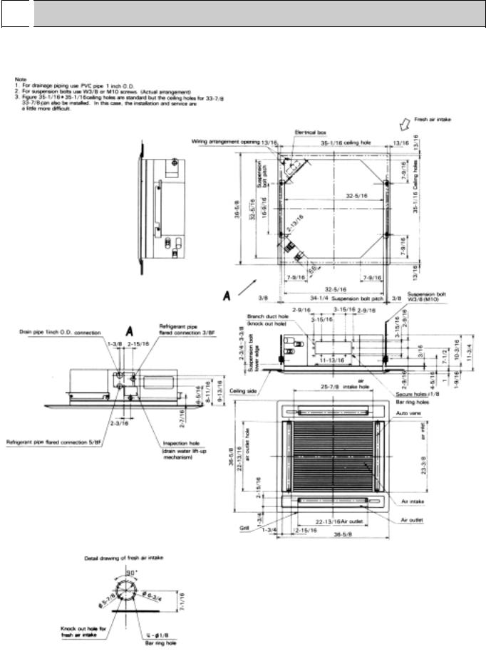
6 
 OUTLINES AND DIMENSIONS
1. INDOOR UNIT |
Unit : inch |
PL12FK1/ 18/24FK21 |
|
OC194-17

|
|
PL30FK21/ 36FK31/ 42FK21 |
Unit : inch |
OC194-18

2.Remote controller
Unit : inch
5-1/8 |
3/32 |
23/32 |
|
|
|
SWING |
|
|
TIMER OFF TIMER |
CLOCK AUTO AUTO |
|
|
FAN |
CHECK SET TEMP. |
START STOP |
FAN |
FILTER |
|
SPEED |
|||
|
|
|
AUTO |
CHECK MODE |
|
|
|
RETURN |
TEST RUN
4-3/4
3/4
7 
 REFRIGERANT SYSTEM DIAGRAM
PL12FK1 |
|
|
|
|
|
|
|
|
|
|
|
|
|
|
|
|
|
|
|
|
|
Unit : inch |
|
|
|
|
|
|
|
|
|
|
|
|
|
|
|
|
|
|
|
|
|
|
|
PL18/24FK21 |
|
|
|
|
|
|
|
|
|
|
|
|
|
|
|
|
|
|
|
|
|
|
|
|
|
|
|
|
|
|
|
|
|
|
|
|
|
|
|
|
|
|
|
|
Refrigerant pipe |
|
|
|
|
|
|
|
|
|
|
|
|
|
|
|
|
|
|
|
|
|
|
(option) |
|
|
|
|
|
|
|
|
|
|
|
|
|
|
|
|
|
|
|
|
|
|
|
|
|
|
|
|
|
|
|
|
|
|
|
|
|
|
|
|
|
|
|
|
|
{5/8" |
|
|
|
|
|
|
|
|
|
|
|
|
|
|
|
|
|
|
|
|
|
|
(with heat insulator) |
|
|
|
|
|
|
|
|
|
|
|
|
|
|
|
|
|
|
|
|
|
|
Flared connection |
|
|
|
|
|
|
|
|
|
|
|
|
|
|
|
|
|
|
|
|
|
|
|
|
|
|
|
|
|
|
|
|
|
|
|
|
|
|
|
|
|
|
|
|
|
|
|
|
|
|
|
|
|
|
|
|
|
|
|
|
|
|
|
|
|
|
|||
|
|
|
|
|
|
|
|
|
|
|
|
|
|
|
|
|
|
Strainer |
||||
|
|
|
|
|
|
|
Indoor coil |
|
|
|
|
|
|
|
Refrigerant pipe |
|||||||
|
|
|
|
|
|
|
|
|
|
|
|
|
|
|||||||||
|
|
|
|
|
|
|
thermistor |
|
|
|
|
|
|
|
||||||||
|
|
|
|
|
|
|
|
|
|
|
|
|
|
(option) |
||||||||
|
|
|
|
|
|
|
RT2 |
|
|
|
|
|
|
|
||||||||
|
|
|
|
|
|
|
|
|
|
|
|
|
|
{3/8" |
||||||||
|
|
|
|
|
|
|
Distributor |
|
|
|
|
|
|
|
(with heat insulator) |
|||||||
|
|
|
|
|
|
|
|
|
|
|
|
|
|
|||||||||
|
|
|
|
|
|
|
|
|
|
|
|
|||||||||||
|
|
|
|
|
|
|
|
|
|
|
|
|
|
|||||||||
|
|
|
|
|
|
|
|
|
|
|
|
|
|
Flared connection |
||||||||
|
|
|
|
|
|
|
|
|
|
|
|
|
|
|
|
|
|
|
|
|
|
|
PL30FK21
PL36FK31
PL42FK21
|
|
|
|
|
|
|
|
|
|
|
|
|
|
|
|
|
|
|
|
|
|
Refrigerant pipe |
|
|
|
|
|
|
|
|
|
|
|
|
|
|
|
|
|
|
|
|
|
|
|
|
|
|
|
|
|
|
|
|
|
|
|
|
|
|
|
|
|
|
|
|
|
(option) |
|
|
|
|
|
|
|
|
|
|
|
|
|
|
|
|
|
|
|
|
|
|
|
|
|
|
|
|
|
|
|
|
|
|
|
|
|
|
|
|
|
|
|
|
|
{3/4" |
|
|
|
|
|
|
|
|
|
|
|
|
|
|
|
|
|
|
|
|
|
|
(with heat insulator) |
|
|
|
|
|
|
|
|
|
|
|
|
|
|
|
|
|
|
|
|
|
|
Flared connection |
|
|
|
|
|
|
|
|
|
|
|
|
|
|
|
|
|
|
|
|
|
|
|
|
|
|
|
|
|
|
|
|
|
|
|
|
|
|
|
|
|
|
|
|||
|
|
|
|
|
|
|
|
|
|
|
|
|
|
|
|
|
|
Strainer |
||||
|
|
|
|
|
|
Indoor coil |
|
|
|
|
|
|
|
|
Refrigerant pipe |
|||||||
|
|
|
|
|
|
|
|
|
|
|
|
|
|
|||||||||
|
|
|
|
|
|
thermistor |
|
|
|
|
|
|
|
|
(option) |
|||||||
|
|
|
|
|
|
RT2 |
|
|
|
|
|
|
|
|
{1/2" |
|||||||
|
|
|
|
|
|
Distributor |
|
|
|
|
|
|
|
|
(with heat insulator) |
|||||||
|
|
|
|
|
|
|
|
|
|
|
|
|
|
|||||||||
|
|
|
|
|
|
|
|
|
|
|
|
|
|
Flared connection |
||||||||
|
|
|
|
|
|
|
|
|
|
|
|
|
|
|||||||||
|
|
|
|
|
|
|
|
|
|
|
|
|
|
|
|
|
|
|
|
|
|
|
OC194-19
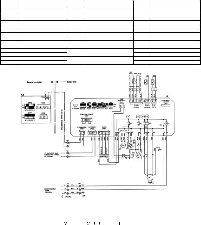
8 |
|
|
WIRING DIAGRAM |
|
|
|
|
|
|
|
|
||
MODELS PL12FK1 PL18FK21 PL24FK21 WIRING DIAGRAM |
|
|
||||
|
|
|
|
|
||
SYMBOL |
NAME |
SYMBOL NAME |
SYMBOL |
NAME |
||
C1 |
Fan motor capacitor |
SW1<I.B> Switch <mode selector> |
X1<I.B> |
Auxiliary relay <drain water lift-up |
||
CN1<R.B> Connector <program timer> |
SW2<I.B> Switch <address selector> |
|
mechanism/dew prevention heater > |
|||
CN2<R.B> Connector <remote switch> |
SW3<I.B> Switch <emergency operation> |
X3<I.B> Auxiliary relay <vane motor> |
||||
CN51<I.B> Connector <centrally control> |
SW5<I.B> Switch <model selector> |
X5<I.B> |
Auxiliary relay <fan motor> |
|||
CN2L<I.B> Connector <lossnay> |
SW6<I.B> |
Switch <model selector> |
|
DP |
Drain water lift-up mechanism |
SW17<R.B> Switch <address selector> |
|
DS |
Drain sensor |
SW18<R.B> Switch <function selector> |
|
F1<I.B> |
Fuse <6A> |
T |
Transformer |
F2 |
Fuse <0.5A> |
TB2,12 |
Terminal block <power> |
H2 |
Dew prevention heater <grille> |
TB4 |
Terminal block <indoor/outdoor connecting line> |
I.B |
Indoor controller board |
TB5,6 |
Terminal block <remote controller transmission line> |
LS |
Limit switch <vane motor> |
TH1 |
Room temperature thermistor |
MF1 |
Fan motor <with inner thermostat> |
|
<32°F/15k", 77°F/5.4k"> |
MV |
Vane motor <with limit thermostat> TH2 |
Pipe temperature thermistor |
|
R.B |
Remote controller board |
|
<32°F/15k", 77°F/5.4k"> |
X6<I.B> Auxiliary relay <fan motor> ZNR Varistor
NOTES:
1.Since the outdoor side electric wiring may change be sure to check the outdoor unit electric wiring for servicing. 2.Indoor and outdoor connecting wires are made with polarities,make wiring matching terminals.
3.Symbols used in wiring diagram above are, :Terminal block, , :connector, :PC board insertion tab. 4.Emergency operation
If a trouble occurs with either the remote controller or the indoor microcomputer and no other trouble exists,emergency operation for cooling can be
performed by changing the setting of dip switch (SW3(I.B)) on the indoor controller board (emergency dry operation is not possible).
OC194-20
MODELS PL30FK21 PL36FK31 PL42FK21 WIRING DIAGRAM
SYMBOL |
NAME |
SYMBOL |
NAME |
SYMBOL |
NAME |
C1,2 |
Fan motor capacitor |
SW1<I.B> |
Switch <mode selector> |
X1<I.B> |
Auxiliary relay <drain water lift-up |
CN1<R.B> Connector <program timer> |
SW2<I.B> |
Switch <address selector> |
|
mechanism/dew prevention heater > |
|
CN2<R.B> Connector <remote switch> |
SW3<I.B> |
Switch <emergency operation> |
X3<I.B> |
Auxiliary relay <vane motor> |
|
CN51<I.B> Connector <centrally control> |
SW5<I.B> |
Switch <model selector> |
X5<I.B> |
Auxiliary relay <fan motor> |
|
CN2L<I.B> Connector <lossnay> |
SW6<I.B> |
Switch <model selector> |
X6<I.B> |
Auxiliary relay <fan motor> |
|
DP |
Drain water lift-up mechanism |
SW17<R.B> Switch <address selector> |
ZNR |
Varistor |
|
DS |
Drain sensor |
SW18<R.B> Switch <function selector> |
|
|
|
F1<I.B> |
Fuse <6A> |
T |
Transformer |
|
|
F2 |
Fuse <0.8A> |
TB2,12 |
Terminal block <power> |
|
|
H2 |
Dew prevention heater <grille> |
TB4 |
Terminal block <indoor/outdoor connecting line> |
|
|
I.B |
Indoor controller board |
TB5,6 |
Terminal block <remote controller transmission line> |
|
|
LS |
Limit switch <vane motor> |
TH1 |
Room temperature thermistor |
|
|
MF1,2 |
Fan motor <with inner thermostat> |
|
<32°F/15k", 77°F/5.4k"> |
|
|
MV |
Vane motor <with limit thermostat> TH2 |
Pipe temperature thermistor |
|
|
|
R.B |
Remote controller board |
|
<32°F/15k", 77°F/5.4k"> |
|
|
NOTES:
1.Since the outdoor side electric wiring may change be sure to check the outdoor unit electric wiring for servicing. 2.Indoor and outdoor connecting wires are made with polarities,make wiring matching terminals.
3.Symbols used in wiring diagram above are, :Terminal block, , :connector, :PC board insertion tab. 4.Emergency operation
If a trouble occurs with either the remote controller or the indoor microcomputer and no other trouble exists,emergency operation for cooling can be
performed by changing the setting of dip switch (SW3(I.B)) on the indoor controller board (emergency dry operation is not possible).
OC194-21
 Loading...