


1997
SPLIT-TYPE, AIR CONDITIONERS
No. OC146
TECHNICAL & SERVICE MANUAL
Series PL Ceiling Cassettes
Indoor unit [Model names]
PL-1.6KJB
PL-2KJB
PL-2.5KJB
[Service Ref.]
PL-1.6KJB.UK PL-2KJB.UK PL-2.5KJB.UK
INDOOR UNIT
TIMER |
TEMP TIMER/TEMP. |
POWER |
ON/OFF |
||
|
|
|
|||
12 |
29 |
|
|
|
|
11 |
28 |
|
COOL |
MODE |
|
10 |
27 |
|
DRY |
||
|
SELECT |
||||
9 |
26 |
|
FAN |
||
|
|
||||
8 |
25 |
UP |
HIGH |
FAN |
|
7 |
24 |
||||
|
LOW |
SPEED |
|||
6 |
23 |
|
|||
|
|
|
|||
5 |
22 |
DOWN |
|
|
|
|
ON |
LOUVER |
|||
4 |
21 |
|
|||
|
|
|
|||
3 |
20 |
|
AUTO |
|
|
2 |
19 |
|
STOP |
TIMER |
|
1 |
18 |
|
START |
MODE |
|
|
|
|
|||
 MITSUBISHI ELECTRIC
REMOTE CONTROLLER
This manual does not cover the following outdoor units. When serving them, please refer to the service manual No.OC149 and this manual in a set.
<Service Ref.>
PU-1.6VLJA2.UK PU-2VJA2.UK PU-2NJA1.UK PU-2.5VJA2.UK PU-2.5NJA1.UK
CONTENTS
1.FEATURES ···········································2
2.PART NAMES AND FUNCTIONS ········3
3.SPECIFICATIONS·································5
4.DATA ·····················································7
5.OUTLINES AND DIMENSIONS··········10
6.WIRING DIAGRAM·····························12
7.REFRIGERANT SYSTEM DIAGRAM ······13
8.OPERATION FLOW-CHART··············14
9.MICROPROCESSOR CONTROL·······17
10.TROUBLESHOOTING ························25
11.4-WAY AIR FLOW SYSTEM ···············27
12.DISASSEMBLY PROCEDURE···········28
13.PARTS LIST········································31
14.OPTIONAL PARTS ·····························35
The Slim Line.
From Mitsubishi Electric.

1 
 FEATURES
Series PL Ceiling Cassettes
TIMER |
TEMP TIMER/TEMP. |
POWER |
ON/OFF |
||
12 |
29 |
|
|
|
|
11 |
28 |
|
COOL |
MODE |
|
10 |
27 |
|
DRY |
||
|
SELECT |
||||
9 |
26 |
|
FAN |
||
|
|
||||
8 |
25 |
UP |
HIGH |
FAN |
|
7 |
24 |
||||
|
LOW |
SPEED |
|||
6 |
23 |
|
|||
|
|
|
|||
5 |
22 |
DOWN |
|
|
|
|
ON |
LOUVER |
|||
4 |
21 |
|
|||
|
|
|
|||
3 |
20 |
|
AUTO |
|
|
|
STOP |
TIMER |
|||
2 |
19 |
|
|||
1 |
18 |
|
START |
MODE |
|
|
|
|
|||
|
|
|
MITSUBISHI ELECTRIC |
||
|
Indoor unit |
Remote controller |
||
|
|
|
||
|
|
|
|
|
Service Ref. |
|
Cooling capacity (50/60Hz) |
|
|
|
|
|
|
|
|
W |
Btu/h |
|
|
|
|
|
||
|
|
|
|
|
PL-1.6KJB.UK |
|
3,800/ – |
13,000/ – |
|
PL-2KJB.UK |
|
5,600/5,400 |
19,100/18,400 |
|
PL-2.5KJB.UK |
|
6,500/7,000 |
22,200/23,900 |
|
|
|
|
|
|
1.PURSUING COMPACTNESS
(1)Panel size and body volume reduced to 64% of previous models
The width and depth of the panel have been reduced by 19cm respectively,resulting in a compact model which fits smaller environments (like shops) perfectly.
(2)Multi-application panels flexibly adapt to installation conditions.
Space panel and Wide panel may be installed on ceilings with shallow depth using the exiting opening .
2."SMUDGE-FREE", PRECISELY TARGETED AIRFLOW SYSTEM
The new control system regulates airflow to prevent smudging. A projection inside the air passage distributes air evenly over the top and bottom of the vane. Two projections on the air outlet work to prevent cooled air from rising to the celling, and also to stop outside air being dragged into the cooled air stream.
3.AIRFLOW ADJUSTABLE TO ANY INDOOR ENVIRONMENT
Airflow can be adjusted according to celling height and the number of air outlets. "Wide Zoming Flow" creates an optimum airflow for any indoor environment.
4.A FURTHER REFINEMENT OF COMFORT WITH NOISE SUPPRESION
The celling 4-way airflow cassette has a special "silent-design". The "2-Tap"system allows a choice between silent and standard modes according to the height of the cellig. For ordinary residenced which have a low celling, selection of the silent mode will result in remarkable noise reductions.
5.ECONOMICAL AND EASY MAINTENANCE
(1)Push-open grill
Filter clogging is widely recognized as a cause of reduced perfomance, but up until now it has been troublesome to clean filters. With the "push-open grill" the fillter can be smoothly opened out at the push of a button, enabling speedy cleaning.
(2)An unprecedented level of vane-cleaning
The unique airflow system prevents the intake of indoor air. Dewing therefore does not occur, and the vane is flockless. The resulting level of dirt on the vane due to tobacco smoke, dust, etc. is very light,and can be wiped off easily with a neutral detergent.
(3)Long-life filter
This new celling 4-way airflow cassette employs a long life fillter which requires no maintenance for up to 2,500 hours of operation in general office environments. It adds uo to an ideal blend of comfort and low maintenance.
2
6.COMPACT DIMENSIONS MEAN EASY INSTALLATION
(1)Carefree suspension work with lightweight unit
The new unit weighs in at 20kg and is easy to handle and install. What's more, suspension work is facillitated by compact dimensions ensuring a snug fit.
(2)Smooth installation with "one-direction"bolts
Suspension bolts can be fixes consistently from one direction easing suspension work.
(3)Trouble-free fitting work with slender refrigerant piping
Refrigerant piping has been reduced in size, and pipe-curving work at the installation site can now be completed quickly and economically. In addition, refrigerant and drain piping are set at different corners, which means that flare connections and drain piping heat insulation work can be smoothly and reliably implemented.
(4)Easy-access terminal and control panels for efficient wiring
When performing wiring work, progress can be checked on the power source terminal and control panels simply by removing the electrical parts cover. Address setting can also be done easily from beneath at a convenient angle.
(5)"One-push"to provisionally position front panel
Panel weight has been redused from 7kg to 3.7kg. The previous 3-step process for provisionally positioning the panel has been streamlined, and now a simple "one-push" action at the diagonal corners fixed it into place, resulting in major time-saving.
2 
 PART NAMES AND FUNCTIONS
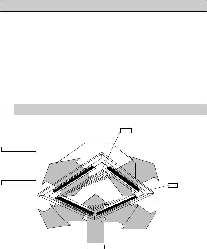
● Indoor Unit
PL-1.6KJB.UK PL-2KJB.UK PL-2.5KJB.UK
Horizontal Air Outlet
Sets airflow horizontal automatically during cooling or dehumidifying.
Downward Air Outlet Sets airflow downward automatically during heating.
Filters
Remove dust and pollutants from inhaled air
Grill
Auto Air Swing Vane Disperses airflow up and down and adjusts the angle of airflow direction.
Air Intake
Inhales air from room.
3
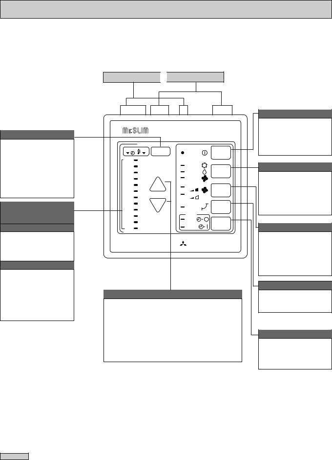
● Controller
TIMER/TEMP. button
This button is used to change between display of room temperature and display of remaining time on the timer during “AUTO STOP” operation.
Green lamps light in selected display mode.
Lamps display remaining time on the timer or room temperature.
Remaining timer time display
Lamps indicate time remaining until timer stops operation. Green lamps display the remaining number of hours.
Room temperature display
Lamps display temperature settings actual room temperatures. ●Temperature settings :
Green lamps light. ●Temperature in room :
Green lamps flash.
(Example display readings are for explanations only, so actual display readings will differ.)
Settings remain in effect' until changed. The air conditioner can be operated by simply pressing ON/OFF button once settings have been made.
Display panel 
 Operating panel
TIMER TEMP TIMER/TEMP. |
POWER |
ON/OFF |
|
12 |
29 |
|
|
|
|
11 |
28 |
|
COOL |
MODE |
|
10 |
27 |
|
DRY |
||
|
SELECT |
||||
9 |
26 |
|
FAN |
||
|
|
||||
8 |
25 |
UP |
HIGH |
FAN |
|
7 |
24 |
||||
|
LOW |
SPEED |
|||
6 |
23 |
|
|||
|
|
|
|||
5 |
22 |
DOWN |
|
|
|
|
ON |
LOUVER |
|||
4 |
21 |
|
|||
|
|
|
|||
3 |
20 |
|
AUTO |
|
|
|
STOP |
TIMER |
|||
2 |
19 |
|
|||
|
START |
MODE |
|||
1 |
18 |
|
|||
|
|
|
|||
|
|
|
MITSUBISHI ELECTRIC |
||
UP and DOWN buttons
●Temperature control (While green “TEMP” lamp is lighting.)
Use UP and DOWN buttons to set desired temperature between 18 and 29 °C.
●Timed operation (While green “TIMER“ lamp is lighting.)
Use UP and DOWN buttons to set timed operation between one and twelve hours.
ON/OFF button
Pressing button starts operation. Pressing again stops operation.
Green lamp remains lit during operation.
MODE SELECT button
This button is used to change between cooling, DRYING and ventilation operation modes. One of three green lamps lights to indicate mode in effect.
FAN SPEED button
This button is used to change between low and high fan speeds. One of two green lamps lights to indicate which fan speed is in effect.
LOUVER button
This button is used to switch swing louver ON/OFF.
TIMER MODE button
Used to select timed starting or stopping. Green lamp lights to indicate timer mode selected.
Attention
●Pressing the UP and DOWN buttons together for more than two seconds will initiate the “test run” or “self-diagnostic” mode. Avoid pressing these buttons simultaneously during normal operation. Press the ON/OFF button to cancel test run or self-
diagnostic mode.
●All green lamps turn off when air conditioner is OFF.
●Avoid operation of buttons with fingernails or other sharp objects. Sharp objects may scratch operating panel.
4
5 
 SPECIFICATIONS
1. STANDARD SPECIFICATIONS
|
Service Ref. |
PL-1.6KJB.UK |
PL-2KJB.UK |
PL-2.5KJB.UK |
|
Item |
|
||||
|
|
|
|
||
|
W |
3,800 |
5,600 |
6,500 |
|
|
50Hz |
13,000 |
19,100 |
22,200 |
|
Cooling capacity w1 |
Btu/h |
||||
W |
– |
5,400 |
7,000 |
||
|
|||||
|
60Hz |
– |
18,400 |
23,900 |
|
|
Btu/h |
||||
Cooling capacity w2 |
W |
– |
4,500 |
5,950 |
|
60Hz |
– |
15,400 |
20,300 |
||
|
Btu/h |
||||
Total input (50/60Hz) w3 |
kW |
1.54/– |
2.57/2.59 |
2.59/3.05 |
|
Service Ref. |
|
PL-1.6KJB.UK |
PL-2KJB.UK |
PL-2.5KJB.UK |
|
External finish |
|
|
Galvanized sheets with gray heat insulation |
|||
|
Fan motor output |
|
kW |
0.03 |
0.03 |
0.03 |
|
|
|
50Hz |
CMM |
13-15 |
13-16 |
14-17 |
|
|
Airflow Lo-Hi |
CFM |
460-530 |
460-565 |
495-600 |
||
|
|
||||||
|
60Hz |
CMM |
13-15 |
13-16 |
14-17 |
||
|
|
||||||
unit |
|
CFM |
460-530 |
460-565 |
495-600 |
||
|
|
||||||
External static pressure |
|
mmAq,Pa |
|
0 (Direct blow) |
|
||
Indoor |
|
|
|
||||
Operation control & Thermostat |
|
|
Remote control & Built-in |
|
|||
|
|
|
|
||||
|
Noise level Low-High |
50Hz |
dB(A) |
31-35 |
32-37 |
35-39.5 |
|
|
60Hz |
dB(A) |
31-35 |
32-37 |
35-39.5 |
||
|
|
||||||
|
Cond. drain connection OD |
|
mm(in.) |
32 (1-1/4) |
32 (1-1/4) |
32 (1-1/4) |
|
|
|
W |
mm(in.) |
660 (26) |
660 (26) |
660 (26) |
|
|
Dimensions |
D |
mm(in.) |
660 (26) |
660 (26) |
660 (26) |
|
|
|
H |
mm(in.) |
253 (10) |
253 (10) |
253 (10) |
|
|
Weight |
|
kg(lbs.) |
19 (42) |
19 (42) |
20 (44) |
|
grill |
External finish |
|
|
|
Munsell 0.70Y 8.59/0.97 |
|
|
|
W |
mm(in.) |
760 (30) |
760 (30) |
760 (30) |
||
|
|
||||||
Indoor |
Dimensions |
D |
mm(in.) |
760 (30) |
760 (30) |
760 (30) |
|
|
|||||||
|
|
H |
mm(in.) |
30 (1-1/8) |
30 (1-1/8) |
30 (1-1/8) |
|
|
Weight |
|
kg(lbs.) |
3.7 (8) |
3.7 (8) |
3.7 (8) |
|
|
Service Ref. |
|
|
PU-1.6VLJA2.UK |
PU-2VJA2.UK, 2NJA1.UK |
PU-2.5VJA2.UK, 2.5NJA1.UK |
|
|
External finish |
|
|
|
Munsell 5Y7/1 |
|
|
|
Refrigerant (R-22) control |
|
|
|
Capillary tube |
|
|
|
Crankcase Heater w4 |
|
W |
– |
32/– |
32/– |
|
unit |
Compressor output |
50/60Hz |
kW |
1.2/- |
2.0/1.5 |
2.0/1.7 |
|
Protection devices |
|
|
Inner thermostat, HP switch, LP switch |
||||
|
|
|
|||||
Outdoor |
Fan motor output |
|
kW |
0.065 |
0.065 |
0.085 |
|
Airflow |
50Hz |
CMM(CFM) |
45(1588) |
45(1588) |
50(1765) |
||
60Hz |
CMM(CFM) |
45(1588) |
45(1588) |
50(1765) |
|||
|
|||||||
|
Noise level |
50/60Hz |
dB(A) |
49/– |
49/50 |
52/53 |
|
|
|
W |
mm(in.) |
870(34-1/4) |
870(34-1/4) |
870(34-1/4) |
|
|
Dimensions |
D |
mm(in.) |
|
295+24(11-5/8+1) |
|
|
|
|
H |
mm(in.) |
650(25-5/8) |
650(25-5/8) |
850(33-7/16) |
|
|
Weight |
|
kg(lbs.) |
45(99) |
60(132) |
71(157) |
|
Notes : |
|
|
|
w1 Rating conditions (JIS B8616) |
w2 Rating conditions (SSA 385, 386) |
||
Indoor : 27°C (80°F) DB, 19°C (66°F)WB |
Indoor : 29°C (84°F) DB, 19°C (66°F)WB |
||
Outdoor : 35°C (95°F) DB, 24°C (75°F)WB |
Outdoor : 46°C (115°F) DB, 24°C (75°F)WB |
||
Refrigerant piping length (one way) : 5m (16ft) |
Refrigerant piping length (one way) : 5m (16ft) |
||
w3 Total input based on indicated voltage |
w4 Capacity of crankcase heater (W) based on 220 volts. |
||
|
(Indoor / Outdoor) |
|
|
|
|
|
|
Service Ref. |
PL-1.6KJB.UK / PL-2KJB.UK / PL-2.5KJB.UK |
|
|
50Hz |
1ph 220V/1ph 220V |
|
|
60Hz |
1ph 220V/1ph 220V |
|
|
Rating conditions (JIS B 8616)
5

2. POWER SUPPLY & MODEL NAMES
Power supply |
Service Ref. (Indoor unit) |
Model name (Outdoor unit) |
||||
|
|
|
||||
PL-1.6KJB.UK |
PL-2KJB.UK |
PL-2.5KJB.UK |
||||
|
|
|
||||
|
|
|
|
|
|
|
50Hz |
1ph. |
220, 230, 240V |
PU-1.6VLJA2.UK |
PU-2VJA2.UK |
PU-2.5VJA2.UK |
|
|
|
|
|
|
||
3ph. |
380/220, 400/230, 415/240V |
– |
– |
– |
||
|
||||||
|
|
|
|
|
|
|
60Hz |
1ph. |
220V |
– |
PU-2NJA1.UK |
PU-2.5NJA1.UK |
|
|
|
|
|
|
||
3ph. |
220V |
– |
– |
– |
||
|
||||||
|
|
|
|
|
|
|
Notes : 1. Power supply key N...1ph, 220V,60Hz
V(L)...1ph, 220, 230, 240V, 50Hz
2.Primary power supplies for all indoor units are single-phase.
3.ELECTRICAL SPECIFICATIONS
(1). Rating conditions - JIS B 8616 Indoor : 27°C (80°F) DB, 19°C (66°F) WB Outdoor : 35°C (95°F) DB, 24°C (75°F) WB
Series PL Indoor Unit (Single Phase)
Power supply (1 Phase) |
|
|
V : 220V 50Hz |
|
|
V : 230V 50Hz |
|
|
|
|
|
|
|
|
|
Service Ref. |
|
PL-1.6KJB.UK |
PL-2KJB.UK |
PL-2.5KJB.UK |
PL-1.6KJB.UK |
PL-2KJB.UK |
PL-2.5KJB.UK |
|
|
|
|
|
|
|
|
Current |
A |
0.59 |
0.60 |
0.60 |
0.62 |
0.63 |
0.63 |
|
|
|
|
|
|
|
|
Input |
kW |
0.12 |
0.13 |
0.13 |
0.13 |
0.14 |
0.14 |
|
|
|
|
|
|
|
|
Starting current |
A |
0.80 |
0.80 |
0.80 |
0.80 |
0.80 |
0.80 |
|
|
|
|
|
|
|
|
Outdoor unit |
|
PU-1.6 |
PU-2 |
PU-2.5 |
PU-1.6 |
PU-2 |
PU-2.5 |
|
|
|
|
|
|
|
|
|
|
|
|
|
|
|
|
Power supply (1 Phase) |
|
|
V : 240V 50Hz |
|
N : 220V 60Hz |
|
|
|
|
|
|
|
|
||
Service Ref. |
|
PL-1.6KJB.UK |
PL-2KJB.UK |
PL-2.5KJB.UK |
PL-2KJB.UK |
PL-2.5KJB.UK |
|
|
|
|
|
|
|
|
|
Current |
A |
0.64 |
0.65 |
0.65 |
0.65 |
0.66 |
|
|
|
|
|
|
|
|
|
Input |
kW |
0.14 |
0.15 |
0.15 |
0.14 |
0.14 |
|
|
|
|
|
|
|
|
|
Starting current |
A |
0.80 |
0.80 |
0.80 |
0.80 |
0.80 |
|
|
|
|
|
|
|
|
|
Outdoor unit |
|
PU-1.6 |
PU-2 |
PU-2.5 |
PU-2 |
PU-2.5 |
|
|
|
|
|
|
|
|
|
6

4 
 DATA
DATA
1. PERFORMANCE DATA
Cooling capacity 50Hz
Service Ref. |
|
|
PL-1.6KJB.UK |
|
PL-2KJB.UK |
|
PL-2.5KJB.UK |
|||||
|
Temperature |
|
T.C. |
|
C.F. |
T.C. |
|
C.F. |
T.C. |
|
C.F. |
|
Outdoor DB |
|
Indoor WB |
|
|
(T.I.) |
|
|
(T.I.) |
|
|
(T.I.) |
|
|
|
16 C (60.8 F) |
3.8 |
|
0.81 |
5.6 |
|
0.81 |
6.5 |
|
0.81 |
|
21 C |
|
18 C (64.4 F) |
4.1 |
|
0.82 |
6.0 |
|
0.82 |
6.9 |
|
0.82 |
|
|
19 C |
(66.2 F) |
4.2 |
|
0.83 |
6.2 |
|
0.83 |
7.2 |
|
0.83 |
|
(69.8 F) |
|
19.4 C |
(67 F) |
4.2 |
|
0.83 |
6.2 |
|
0.83 |
7.3 |
|
0.83 |
|
|
20 C |
(68 F) |
4.3 |
|
0.84 |
6.4 |
|
0.84 |
7.4 |
|
0.84 |
|
|
22 C (71.6 F) |
4.6 |
|
0.86 |
6.7 |
|
0.86 |
7.8 |
|
0.86 |
|
|
|
16 C (60.8 F) |
3.7 |
|
0.84 |
5.5 |
|
0.84 |
6.4 |
|
0.84 |
|
25 C |
|
18 C (64.4 F) |
4.0 |
|
0.85 |
5.9 |
|
0.85 |
6.8 |
|
0.85 |
|
|
19 C |
(66.2 F) |
4.1 |
|
0.86 |
6.0 |
|
0.86 |
7.0 |
|
0.86 |
|
(77 F) |
|
19.4 C |
(67 F) |
4.2 |
|
0.86 |
6.1 |
|
0.86 |
7.1 |
|
0.86 |
|
|
20 C |
(68 F) |
4.2 |
|
0.87 |
6..2 |
|
0.87 |
7.2 |
|
0.87 |
|
|
22 C (71.6 F) |
4.5 |
|
0.89 |
6.6 |
|
0.89 |
7.7 |
|
0.89 |
|
|
|
16 C (60.8 F) |
3.6 |
|
0.90 |
5.3 |
|
0.90 |
6.1 |
|
0.90 |
|
30 C |
|
18 C (64.4 F) |
3.8 |
|
0.92 |
5.6 |
|
0.92 |
6.6 |
|
0.92 |
|
|
19 C |
(66.2 F) |
4.0 |
|
0.93 |
5.8 |
|
0.93 |
6.8 |
|
0.93 |
|
(86 F) |
|
19.4 C |
(67 F) |
4.0 |
|
0.93 |
5.9 |
|
0.93 |
6.9 |
|
0.93 |
|
|
20 C |
(68 F) |
4.1 |
|
0.94 |
6.0 |
|
0.94 |
7.0 |
|
0.94 |
|
|
22 C (71.6 F) |
4.3 |
|
0.96 |
6.4 |
|
0.96 |
7.4 |
|
0.96 |
|
|
|
16 C (60.8 F) |
3.5 |
|
0.93 |
5.2 |
|
0.93 |
6.0 |
|
0.93 |
|
32.2 C |
|
18 C (64.4 F) |
3.8 |
|
0.95 |
5.5 |
|
0.95 |
6.4 |
|
0.95 |
|
|
19 C |
(66.2 F) |
3.9 |
|
0.96 |
5.7 |
|
0.96 |
6.6 |
|
0.96 |
|
(90 F) |
|
19.4 C |
(67 F) |
3.9 |
|
0.97 |
5.8 |
|
0.97 |
6.7 |
|
0.97 |
|
|
20 C |
(68 F) |
4.0 |
|
0.97 |
5.9 |
|
0.97 |
6.9 |
|
0.97 |
|
|
22 C (71.6 F) |
4.3 |
|
0.99 |
6.3 |
|
0.99 |
7.3 |
|
0.99 |
|
|
|
16 C (60.8 F) |
3.4 |
|
0.96 |
5.1 |
|
0.96 |
5.9 |
|
0.96 |
|
35 C |
|
18 C (64.4 F) |
3.7 |
|
0.99 |
5.4 |
|
0.99 |
6.3 |
|
0.99 |
|
|
19 C |
(66.2 F) |
3.8 |
|
1.00 |
5.6 |
|
1.00 |
6.5 |
|
1.00 |
|
(95 F) |
|
19.4 C |
(67 F) |
3.8 |
|
1.00 |
5.7 |
|
1.00 |
6.6 |
|
1.00 |
|
|
20 C |
(68 F) |
3.9 |
|
1.01 |
5.8 |
|
1.01 |
6.7 |
|
1.01 |
|
|
22 C (71.6 F) |
4.2 |
|
1.04 |
6.2 |
|
1.04 |
7.2 |
|
1.04 |
|
|
|
16 C (60.8 F) |
3.3 |
|
1.03 |
4.9 |
|
1.03 |
5.6 |
|
1.03 |
|
40 C |
|
18 C (64.4 F) |
3.5 |
|
1.06 |
5.2 |
|
1.06 |
6.0 |
|
1.06 |
|
|
19 C |
(66.2 F) |
3.6 |
|
1.07 |
5.4 |
|
1.07 |
6.2 |
|
1.07 |
|
(104 F) |
|
19.4 C |
(67 F) |
3.7 |
|
1.08 |
5.4 |
|
1.08 |
6.3 |
|
1.08 |
|
|
20 C |
(68 F) |
3.8 |
|
1.08 |
5.5 |
|
1.08 |
6.4 |
|
1.08 |
|
|
22 C (71.6 F) |
4.0 |
|
1.11 |
5.9 |
|
1.11 |
6.9 |
|
1.11 |
|
|
|
16 C (60.8 F) |
3.3 |
|
1.04 |
4.8 |
|
1.04 |
5.6 |
|
1.04 |
|
40.6 C |
|
18 C (64.4 F) |
3.5 |
|
1.06 |
5.2 |
|
1.06 |
6.0 |
|
1.06 |
|
|
19 C |
(66.2 F) |
3.6 |
|
1.08 |
5.3 |
|
1.08 |
6.2 |
|
1.08 |
|
(105 F) |
|
19.4 C |
(67 F) |
3.7 |
|
1.08 |
5.4 |
|
1.08 |
6.3 |
|
1.08 |
|
|
20 C |
(68 F) |
3.7 |
|
1.09 |
5.5 |
|
1.09 |
6.4 |
|
1.09 |
|
|
22 C (71.6 F) |
4.0 |
|
1.12 |
5.9 |
|
1.12 |
6.8 |
|
1.12 |
|
|
|
16 C (60.8 F) |
3.1 |
|
1.10 |
4.6 |
|
1.10 |
5.4 |
|
1.10 |
|
45 C |
|
18 C (64.4 F) |
3.4 |
|
1.12 |
4.9 |
|
1.12 |
5.7 |
|
1.12 |
|
|
19 C |
(66.2 F) |
3.5 |
|
1.14 |
5.1 |
|
1.14 |
5.9 |
|
1.14 |
|
(113 F) |
|
19.4 C |
(67 F) |
3.5 |
|
1.15 |
5.2 |
|
1.15 |
6.0 |
|
1.15 |
|
|
20 C |
(68 F) |
3.6 |
|
1.16 |
5.3 |
|
1.16 |
6.1 |
|
1.16 |
|
|
22 C (71.6 F) |
3.8 |
|
1.20 |
5.7 |
|
1.20 |
6.6 |
|
1.20 |
|
|
|
16 C (60.8 F) |
3.1 |
|
1.11 |
4.6 |
|
1.11 |
5.3 |
|
1.11 |
|
46 C |
|
18 C (64.4 F) |
3.3 |
|
1.14 |
4.9 |
|
1.14 |
5.7 |
|
1.14 |
|
|
19 C |
(66.2 F) |
3.4 |
|
1.15 |
5.1 |
|
1.15 |
5.9 |
|
1.15 |
|
(115 F) |
|
19.4 C |
(67 F) |
3.5 |
|
1.16 |
5.1 |
|
1.16 |
6.0 |
|
1.16 |
|
|
20 C |
(68 F) |
3.6 |
|
1.17 |
5.2 |
|
1.17 |
6.1 |
|
1.17 |
|
|
22 C (71.6 F) |
3.8 |
|
1.21 |
5.6 |
|
1.21 |
6.5 |
|
1.21 |
|
|
|
16 C (60.8 F) |
3.0 |
|
1.16 |
4.4 |
|
1.16 |
5.1 |
|
1.16 |
|
50 C |
|
18 C (64.4 F) |
3.2 |
|
1.19 |
4.7 |
|
1.19 |
5.4 |
|
1.19 |
|
|
19 C |
(66.2 F) |
3.3 |
|
1.21 |
4.9 |
|
1.21 |
5.6 |
|
1.21 |
|
(69.8 F) |
|
19.4 C |
(67 F) |
3.3 |
|
1.22 |
4.9 |
|
1.22 |
5.7 |
|
1.22 |
|
|
20 C |
(68 F) |
3.4 |
|
1.23 |
5.0 |
|
1.23 |
5.8 |
|
1.23 |
|
|
22 C (71.6 F) |
3.7 |
|
1.28 |
5.4 |
|
1.28 |
6.3 |
|
1.28 |
|
|
|
16 C (60.8 F) |
2.9 |
|
1.19 |
4.3 |
|
1.19 |
4.9 |
|
1.19 |
|
52 C |
|
18 C (64.4 F) |
3.1 |
|
1.22 |
4.6 |
|
1.22 |
5.3 |
|
1.22 |
|
|
19 C |
(66.2 F) |
3.2 |
|
1.24 |
4.7 |
|
1.24 |
5.5 |
|
1.24 |
|
(125.5 F) |
|
19.4 C |
(67 F) |
3.3 |
|
1.25 |
4.8 |
|
1.25 |
5.6 |
|
1.25 |
|
|
20 C |
(68 F) |
3.3 |
|
1.26 |
4.9 |
|
1.26 |
5.7 |
|
1.26 |
|
|
22 C (71.6 F) |
3.6 |
|
1.31 |
5.3 |
|
1.31 |
6.1 |
|
1.31 |
|
Evaporator airflow (CMM) |
|
15 |
|
16 |
|
17 |
||||||
Bypass factors |
|
|
0.21 |
|
0.20 |
|
0.14 |
|||||
S.H.F. at rating conditions |
|
0.67 |
|
0.74 |
|
0.72 |
||||||
Notes : 1. T.C. : Total capacity (kW) ... (kcal/h) = (kW) o 860, (Btu/h) = 4 o (kW) o 860
C.F. (T.I.) : Correction factors of Total input (Indoor unit input + Outdoor unit input)
2.(°F) = 32 + 9 / 5 (°C)
3.Guaranteed operation range (cooling) :
Lower limit ... Indoor : 21°C (70°F) DB, 15.5°C (60°F) WB, Outdoor : 21°C (70°F) DB. Upper limit ... Indoor : 35°C (95°F) DB, 22.5°C (72.5°F) WB, Outdoor : 52°C (125.5°F) DB.
wVL ... Outdoor : 46°C (115°F) DB.
Cooling capacity correction factors 50Hz
Service Ref. |
|
|
Refrigerant piping length (one way) |
|
|
||||
5m (16ft) |
10m (33ft) |
15m (49ft) |
20m (66ft) |
25m (82ft) |
30m (98ft) |
35m (115ft) |
40m (131ft) |
||
|
|||||||||
PL-1.6KJB.UK |
1.0 |
0.992 |
0.987 |
0.982 |
– |
– |
– |
– |
|
PL-2KJB.UK |
1.0 |
0.985 |
0.975 |
0.964 |
0.954 |
0.944 |
– |
– |
|
PL-2.5KJB.UK |
1.0 |
0.983 |
0.972 |
0.961 |
0.951 |
0.940 |
– |
– |
|
7

Cooling capacity 60Hz
Service Ref. |
|
|
PL-2KJB.UK |
|
PL-2.5KJB.UK |
||||
|
Temperature |
|
T.C. |
|
C.F. |
T.C. |
|
C.F. |
|
Outdoor DB |
|
Indoor WB |
|
|
(T.I.) |
|
|
(T.I.) |
|
|
|
16 C (60.8 F) |
5.4 |
|
0.81 |
7.0 |
|
0.81 |
|
21 C |
|
18 C (64.4 F) |
5.8 |
|
0.82 |
7.5 |
|
0.82 |
|
|
19 C |
(66.2 F) |
6.0 |
|
0.83 |
7.7 |
|
0.83 |
|
(69.8 F) |
|
19.4 C |
(67 F) |
6.0 |
|
0.83 |
7.8 |
|
0.83 |
|
|
20 C |
(68 F) |
6.1 |
|
0.84 |
7.9 |
|
0.84 |
|
|
22 C (71.6 F) |
6.5 |
|
0.86 |
8.4 |
|
0.86 |
|
|
|
16 C (60.8 F) |
5.3 |
|
0.84 |
6.9 |
|
0.84 |
|
25 C |
|
18 C (64.4 F) |
5.6 |
|
0.85 |
7.3 |
|
0.85 |
|
|
19 C |
(66.2 F) |
5.8 |
|
0.86 |
7.6 |
|
0.86 |
|
(77 F) |
|
19.4 C |
(67 F) |
5.9 |
|
0.86 |
7.7 |
|
0.86 |
|
|
20 C |
(68 F) |
6.0 |
|
0.87 |
7.8 |
|
0.87 |
|
|
22 C (71.6 F) |
6.4 |
|
0.89 |
8.3 |
|
0.89 |
|
|
|
16 C (60.8 F) |
5.1 |
|
0.90 |
6.6 |
|
0.90 |
|
30 C |
|
18 C (64.4 F) |
5.4 |
|
0.92 |
7.1 |
|
0.92 |
|
|
19 C |
(66.2 F) |
5.6 |
|
0.93 |
7.3 |
|
0.93 |
|
(86 F) |
|
19.4 C |
(67 F) |
5.7 |
|
0.93 |
7.4 |
|
0.93 |
|
|
20 C |
(68 F) |
5.8 |
|
0.94 |
7.5 |
|
0.94 |
|
|
22 C (71.6 F) |
6.2 |
|
0.96 |
8.0 |
|
0.96 |
|
|
|
16 C (60.8 F) |
5.0 |
|
0.93 |
6.5 |
|
0.93 |
|
32.2 C |
|
18 C (64.4 F) |
5.3 |
|
0.95 |
6.9 |
|
0.95 |
|
|
19 C |
(66.2 F) |
5.5 |
|
0.96 |
7.2 |
|
0.96 |
|
(90 F) |
|
19.4 C |
(67 F) |
5.6 |
|
0.97 |
7.3 |
|
0.97 |
|
|
20 C |
(68 F) |
5.7 |
|
0.97 |
7.4 |
|
0.97 |
|
|
22 C (71.6 F) |
6.1 |
|
0.99 |
7.9 |
|
0.99 |
|
|
|
16 C (60.8 F) |
4.9 |
|
0.96 |
6.3 |
|
0.96 |
|
35 C |
|
18 C (64.4 F) |
5.2 |
|
0.99 |
6.8 |
|
0.99 |
|
|
19 C |
(66.2 F) |
5.4 |
|
1.00 |
7.0 |
|
1.00 |
|
(95 F) |
|
19.4 C |
(67 F) |
5.5 |
|
1.00 |
7.1 |
|
1.00 |
|
|
20 C |
(68 F) |
5.6 |
|
1.01 |
7.2 |
|
1.01 |
|
|
22 C (71.6 F) |
5.9 |
|
1.04 |
7.7 |
|
1.04 |
|
|
|
16 C (60.8 F) |
4.7 |
|
1.03 |
6.1 |
|
1.03 |
|
40 C |
|
18 C (64.4 F) |
5.0 |
|
1.06 |
6.5 |
|
1.06 |
|
|
19 C |
(66.2 F) |
5.2 |
|
1.07 |
6.7 |
|
1.07 |
|
(104 F) |
|
19.4 C |
(67 F) |
5.2 |
|
1.08 |
6.8 |
|
1.08 |
|
|
20 C |
(68 F) |
5.3 |
|
1.08 |
6.9 |
|
1.08 |
|
|
22 C (71.6 F) |
5.7 |
|
1.11 |
7.4 |
|
1.11 |
|
|
|
16 C (60.8 F) |
4.7 |
|
1.04 |
6.0 |
|
1.04 |
|
40.6 C |
|
18 C (64.4 F) |
5.0 |
|
1.06 |
6.4 |
|
1.06 |
|
|
19 C |
(66.2 F) |
5.1 |
|
1.08 |
6.7 |
|
1.08 |
|
(105 F) |
|
19.4 C |
(67 F) |
5.2 |
|
1.08 |
6.8 |
|
1.08 |
|
|
20 C |
(68 F) |
5.3 |
|
1.09 |
6.9 |
|
1.09 |
|
|
22 C (71.6 F) |
5.7 |
|
1.12 |
7.4 |
|
1.12 |
|
|
|
16 C (60.8 F) |
4.4 |
|
1.10 |
5.8 |
|
1.10 |
|
45 C |
|
18 C (64.4 F) |
4.8 |
|
1.12 |
6.2 |
|
1.12 |
|
|
19 C |
(66.2 F) |
4.9 |
|
1.14 |
6.4 |
|
1.14 |
|
(113 F) |
|
19.4 C |
(67 F) |
5.0 |
|
1.15 |
6.5 |
|
1.15 |
|
|
20 C |
(68 F) |
5.1 |
|
1.16 |
6.6 |
|
1.16 |
|
|
22 C (71.6 F) |
5.5 |
|
1.20 |
7.1 |
|
1.20 |
|
|
|
16 C (60.8 F) |
4.4 |
|
1.11 |
5.7 |
|
1.11 |
|
46 C |
|
18 C (64.4 F) |
4.7 |
|
1.14 |
6.1 |
|
1.14 |
|
|
19 C |
(66.2 F) |
4.9 |
|
1.15 |
6.3 |
|
1.15 |
|
(115 F) |
|
19.4 C |
(67 F) |
4.9 |
|
1.16 |
6.4 |
|
1.16 |
|
|
20 C |
(68 F) |
5.0 |
|
1.17 |
6.5 |
|
1.17 |
|
|
22 C (71.6 F) |
5.4 |
|
1.21 |
7.0 |
|
1.21 |
|
|
|
16 C (60.8 F) |
4.2 |
|
1.16 |
5.5 |
|
1.16 |
|
50 C |
|
18 C (64.4 F) |
4.5 |
|
1.19 |
5.9 |
|
1.19 |
|
|
19 C |
(66.2 F) |
4.7 |
|
1.21 |
6.1 |
|
1.21 |
|
(122 F) |
|
19.4 C |
(67 F) |
4.7 |
|
1.22 |
6.2 |
|
1.22 |
|
|
20 C |
(68 F) |
4.8 |
|
1.23 |
6.3 |
|
1.23 |
|
|
22 C (71.6 F) |
5.2 |
|
1.28 |
6.7 |
|
1.28 |
|
|
|
16 C (60.8 F) |
4.1 |
|
1.19 |
5.3 |
|
1.19 |
|
52 C |
|
18 C (64.4 F) |
4.4 |
|
1.22 |
5.7 |
|
1.22 |
|
|
19 C |
(66.2 F) |
4.6 |
|
1.24 |
5.9 |
|
1.24 |
|
(125.5 F) |
|
19.4 C |
(67 F) |
4.6 |
|
1.25 |
6.0 |
|
1.25 |
|
|
20 C |
(68 F) |
4.7 |
|
1.26 |
6.1 |
|
1.26 |
|
|
22 C (71.6 F) |
5.1 |
|
1.31 |
6.6 |
|
1.31 |
|
Evaporator airflow (CMM) |
|
16 |
|
17 |
|||||
Bypass factors |
|
|
0.21 |
|
0.20 |
||||
S.H.F. at rating conditions |
|
0.68 |
|
0.75 |
|||||
Notes : 1. T.C. : Total capacity (kW) ... (kcal/h) = (kW) o 860, (Btu/h) = 4 o (kW) o 860
C.F. (T.I.) : Correction factors of Total input (Indoor unit input + Outdoor unit input)
2.(°F) = 32 + 9 / 5 (°C)
3.Guaranteed operation range (cooling) :
Lower limit ... Indoor : 21°C |
(70°F) |
DB, 15.5°C |
(60°F) WB, Outdoor : 21°C (70°F) DB. |
Upper limit ... Indoor : 35°C |
(95°F) |
DB, 22.5°C |
(72.5°F) WB, Outdoor : 52°C (125.5°F) DB. |
Cooling capacity correction factors 60Hz
Service Ref. |
|
|
Refrigerant piping length (one way) |
|
|
||||
5m (16ft) |
10m (33ft) |
15m (49ft) |
20m (66ft) |
25m (82ft) |
30m (98ft) |
35m (115ft) |
40m (131ft) |
||
|
|||||||||
PL-2KJB.UK |
1.0 |
0.985 |
0.975 |
0.964 |
0.954 |
0.944 |
– |
– |
|
PL-2.5KJB.UK |
1.0 |
0.978 |
0.963 |
0.948 |
0.934 |
0.921 |
– |
– |
|
8

2. STANDARD OPERATION DATA
|
Service Ref. |
|
|
PL-1.6KJB.UK |
PL-2KJB.UK |
|
|
|
|
PL-2.5KJB.UK |
||||||||
|
|
|
|
|
|
|
|
|
|
|
|
|
|
|
|
|
||
|
MODE |
|
|
cooling |
cooling |
|
cooling |
|
cooling |
|
cooling |
|||||||
|
|
|
|
|
|
|
|
|
|
|
|
|
|
|
|
|
||
Total |
Capacity |
|
|
W |
3,800 |
|
5,600 |
|
5,400 |
|
6,500 |
|
7,000 |
|||||
|
|
|
|
|
|
|
|
|
|
|
|
|
|
|
|
|
||
Input |
|
|
kW |
1.54 |
|
2.57 |
|
|
2.59 |
|
2.59 |
|
3.05 |
|||||
|
|
|
|
|
|
|
|
|||||||||||
|
|
|
|
|
|
|
|
|
|
|
|
|
|
|
|
|
||
|
Indoor unit Service Ref. |
|
|
PL-1.6KJB.UK |
PL-2KJB.UK |
|
|
|
|
PL-2.5KJB.UK |
||||||||
|
|
|
|
|
|
|
|
|
|
|
|
|
|
|
|
|||
circuit |
phase, Hz |
|
|
|
1, 50 |
|
1, 50 |
|
|
1, 60 |
|
1, 50 |
|
1, 60 |
||||
|
|
|
|
|
|
|
|
|
|
|
|
|
|
|
|
|
||
Volts |
|
|
|
220 |
|
220 |
|
|
|
220 |
|
220 |
|
220 |
||||
|
|
|
|
|
|
|
|
|
|
|||||||||
|
|
|
|
|
|
|
|
|
|
|
|
|
|
|
|
|
||
Electrical |
Amperes |
|
|
|
0.59 |
|
0.60 |
|
|
0.65 |
|
0.60 |
|
0.66 |
||||
|
|
|
|
|
|
|
|
|
|
|
|
|
|
|
|
|
||
Outdoor unit Service Ref. |
PU-1.6VLJA2.UK |
PU-2VJA2.UK |
PU-2NJA1.UK |
PU-2.5VJA2.UK |
PU-2.5NJA1.UK |
|||||||||||||
|
||||||||||||||||||
|
|
|
|
|
|
|
|
|
|
|
|
|
|
|
|
|
||
|
phase, Hz |
|
|
|
1, 50 |
|
1, 50 |
|
|
1, 60 |
|
1, 50 |
|
1, 60 |
||||
|
|
|
|
|
|
|
|
|
|
|
|
|
|
|
|
|
|
|
|
Volts |
|
|
|
220 |
|
220 |
|
|
|
220 |
|
220 |
|
220 |
|||
|
|
|
|
|
|
|
|
|
|
|
|
|
|
|
|
|
||
|
Amperes |
|
|
|
6.7 |
|
11.3 |
|
|
11.4 |
|
11.4 |
|
13.4 |
||||
|
|
|
|
|
|
|
|
|
|
|
|
|
|
|
|
|
||
|
Discharge pressure |
|
Mpa·G |
1.94 |
|
1.95 |
|
|
1.95 |
|
1.92 |
|
2.03 |
|||||
|
|
(kgf/FG) |
(19.8) |
|
(19.9) |
|
(19.9) |
|
(19.6) |
|
(20.7) |
|||||||
circuit |
|
|
|
|
|
|
|
|||||||||||
|
|
|
|
|
|
|
|
|
|
|
|
|
|
|
|
|
||
Suction pressure |
|
Mpa·G |
0.52 |
|
0.45 |
|
|
0.48 |
|
0.48 |
|
0.47 |
||||||
|
|
|
|
|
|
|
||||||||||||
|
|
(kgf/FG) |
(5.3) |
|
(4.6) |
|
|
(4.9) |
|
(4.9) |
|
(4.8) |
||||||
Refrigerant |
|
|
|
|
|
|
|
|
||||||||||
|
|
|
|
|
|
|
|
|
|
|
|
|
|
|
|
|
||
Discharge temperature |
|
C |
62.3 |
|
75.9 |
|
|
63.6 |
|
74.3 |
|
83.4 |
||||||
|
|
|
|
|
|
|
||||||||||||
|
|
|
|
|
|
|
|
|
|
|
|
|
|
|
|
|
||
|
Condensing temperature |
|
C |
37.4 |
|
48.9 |
|
|
46.0 |
|
46.4 |
|
47.6 |
|||||
|
|
|
|
|
|
|
|
|
|
|
|
|
|
|
|
|
|
|
|
Suction temperature |
|
C |
6.3 |
|
13.1 |
|
|
|
5.8 |
|
10.3 |
|
7.2 |
||||
|
|
|
|
|
|
|
|
|
|
|
|
|
|
|
|
|
|
|
|
Ref. pipe length |
|
m |
5 |
|
5 |
|
|
|
5 |
|
5 |
|
5 |
||||
|
|
|
|
|
|
|
|
|
|
|
|
|
|
|
|
|
|
|
side |
Intake air temperature |
|
DB C |
27 |
|
27 |
|
|
|
27 |
|
27 |
|
27 |
||||
|
|
|
|
|
|
|
|
|||||||||||
Indoor |
|
|
|
|
|
|
|
|
|
|
|
|
|
|
|
|||
|
DB C |
17.1 |
|
15.5 |
|
|
14.6 |
|
13.1 |
|
13.0 |
|||||||
Discharge air temperature |
|
|
|
|
|
|
||||||||||||
|
|
|
|
WB C |
19 |
|
19 |
|
|
|
19 |
|
19 |
|
19 |
|||
|
|
|
|
|
|
|
|
|
|
|
|
|
|
|
|
|
|
|
Outdoor side |
Intake air temperature |
|
DB C |
35 |
|
35 |
|
|
|
35 |
|
35 |
|
35 |
||||
|
|
|
|
|
|
|
|
|||||||||||
|
|
|
|
|
|
|
|
|
|
|
|
|
|
|
|
|||
|
|
WB C |
24 |
|
24 |
|
|
|
24 |
|
24 |
|
24 |
|||||
|
|
|
|
|
|
|
|
|
|
|||||||||
|
|
|
|
|
|
|
|
|
|
|
|
|
|
|
||||
The unit of pressure has been changed to Mpa based on the international SI system. |
|
|
|
|
||||||||||||||
The conversion factor is : 1(Mpa·G)=10.2(kgf/F·G) |
|
|
|
|
|
|
|
|
|
|
|
|||||||
3. ADDITIONAL REFRIGERANT CHARGE (R-22......Kg(lbs)) |
|
|
|
|
|
|
|
|||||||||||
Service Ref. |
Outdoor unit precharged (kg) |
|
|
|
Refrigerant piping length (one way) |
|
||||||||||||
|
(up to 20m) |
|
|
|
|
|
|
|
|
|
|
|
|
|
||||
|
|
20m(66ft) |
|
25m(82ft) |
|
30m(98ft) |
|
35m(115ft) |
40m(131ft) |
|||||||||
|
|
|
|
|
|
|
||||||||||||
|
|
|
|
|
|
|
|
|
|
|
|
|
|
|
||||
PL-1.6KJB.UK |
V...1.3 |
|
|
|
|
0 |
|
|
– |
|
– |
|
– |
– |
||||
PL-2KJB.UK |
V...1.78, N...1.9 |
|
|
0 |
|
0.06(0.13) |
|
0.12(0.26) |
|
– |
– |
|||||||
PL-2.5KJB.UK |
V...2.4, N...2.4 |
|
|
0 |
|
0.06(0.13) |
|
0.12(0.26) |
|
– |
– |
|||||||
4. OUTLET AIR SPEED AND COVERAGE RANGE
|
|
|
PL-1.6KJB.UK |
PL-2KJB.UK |
PL-2.5KJB.UK |
|
|
|
|
|
|
|
|
Standard |
Air flow |
CMM |
15.0 |
16.0 |
17.0 |
|
|
|
|
|
|
||
Coverage range |
m |
5.7 |
6.0 |
6.4 |
||
|
Air speed |
m/sec. |
5.2 |
5.6 |
5.9 |
|
|
|
|
|
|
|
|
ceiling |
Air flow |
CMM |
16.0 |
17.0 |
18.0 |
|
|
|
|
|
|
||
Air speed |
m/sec. |
5.6 |
5.9 |
6.3 |
||
|
||||||
|
|
|
|
|
|
|
High |
Coverage range |
m |
6.0 |
6.4 |
6.8 |
|
|
|
|
|
|
||
Total width of discharge outlets |
mm |
0 |
0 |
0 |
||
|
||||||
|
|
|
|
|
|
w The air coverage range is the value up to the position where the air speed is 0.25 m/sec. when air is blown out horizontally from the unit at the Hi notch position.
The coverage range should be used only as a general guideline since it varies according to the size of the room and furniture inside the room.
9
5 
 OUTLINES AND DIMENSIONS
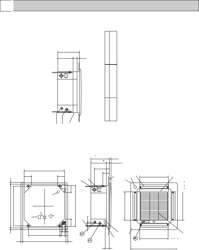
1.INDOOR UNIT
PL-1.6KJB.UK / PL-2KJB.UK / PL-2.5KJB.UK
partselectricalForNOTE1.box may be removed during servicing. When |
powertheconnectingline and the control wire, provide enough length to |
wires.electricthe |
theinstallingWhenNOTE2.optional high-efficiency filter, the dimension |
transomthebetweenand ceiling shall be more than 440mm. Also,when |
optionaltheinstallingcasement, the dimension between the transom |
morebeshallceilingand than 440m. (The optional highefficiency filter |
installed.)bealsocan |
|
|
pipeLiquid |
|
pipeGas |
hilterefficiency |
|
|
|
|
|
|
|
|
|
|
|
|
|
|
|
|
|
|
435 |
|
|
|
|
|
|
|
|
|
|
|
|
|
|
|
|
|
|
135 |
|
|
45 |
|
|
|
|
|
|
|
|
|
|
|
|
|
|
|
Optional high- |
|
|
|
|
|
|
|
|
|
|
|
|
|
660 |
|
|
|
|
|
|
Drainhole 25-VPconnection |
Feedinghole |
(Drainpump) |
|
|
|
|
|
|
|
|
|
|
|
|
|
|
|
|
|
|
|
|
|
|
25~35 690~710 25~35 |
|
|
|
|
117 |
|
|
|
117 |
|
|
|
|
|
||
|
Ceiling hole |
640 |
Suspension bolt pitch |
|
|
Terminal block for control |
Terminal block for remote controller |
Drain hole |
Terminal block for |
power supply |
|
117 117 |
660 |
Suspension bolt M10 or |
W3/8 |
41 25 |
||
|
|
|
|
|
|
|
|
Suspensionboltpitch |
|
53 |
|
|
|
|
|
|||
|
|
|
|
|
|
|
|
|
|
|
|
|
|
|
|
|
|
|
|
|
|
|
|
|
|
|
507 |
|
|
|
54 |
|
|
|
|
|
|
|
|
|
|
|
25~35 |
690~710 |
|
|
|
25~35 |
|
|
|
|
|
|||
|
|
|
|
|
Ceilinghole |
|
|
|
|
|
|
|
|
|||||
|
|
|
|
|
|
|
|
|
|
|
|
|
|
|
|
|
||
loweredge
|
2 |
Refrigerant pipe Ø15.88 |
Flared connection 5/8F |
|
|
|
|
|
1 |
Refrigerant pipe Ø9.52 |
Flared connection 3/8F |
|
|
|
|
between the |
the ceiling slab. |
1.6/2/2.5KJ |
|
|
|
|
|
Leave space of 10~15mm |
top surface of the unit and |
|
surface |
|
panelDecorative |
motorVane |
vanesAuto-4 |
|
293 |
|
|
||||
|
|
30 |
|
|
|
|
|
253 |
|
-2 |
54 |
|
|
|
|
|
|
|
+3 |
|
|
|
|
|
243 |
|
|
|
|
|
|
|
|
|
|
|
|
|
|
|
115 |
|
|
|
|
|
|
|
|
|
Ceiling |
|
|
|
|
|
|
|
|
|
466 |
intake hole |
|
|
|
|
|
|
|
Air |
|
|
|
|
Controlwire entry Power line entry |
side |
side |
|
|
|
65~80 |
Refrigerant piping |
electric wire entry |
|
|||
Suspensionbolt |
|
|
|
|
|
|
|
Airoutlethole
466
Airoutlethole
460
760
Unit : mm
|
Intake grill opening/closing side |
35 |
|
|
|
|
|
|
|||
|
|
|
|
|
|
|
|
|
|
|
|
|
|
|
66 |
|
|
|
|
|
|
|
|
|
|
|
460 outlet hole 760 |
||
|
|
|
Air |
||
|
|
|
|
|
|
|
|
|
|
|
|
|
|
grill |
|
|
|
|
|
66 |
|
35 |
||
|
|
|
|
Airintake |
|
|
|
|
|
10
2. REMOTE CONTROLLER
Unit : mm (inch)
3
75 |
69 |
||
|
|
|
|
|
|
|
|
|
|
3 |
|
|
|
96.5 |
|
|
|
12(15/32) |
Upper side wiring |
|
12(15/32) |
|
|
|
|
|
|
arrangement |
|
||
3 |
|
90.5 |
|
|
3 |
11.6 |
|
|
|
|
|
|
opening |
8 |
6 |
||||
|
|
|
3.6 |
||||||
|
|
|
|
|
|
|
|||
|
|
|
|
|
|
|
|
|
|
TIMER |
TEMP |
TIMER/TEMP. |
POWER |
ON/OFF |
|
|
|
|
46 |
|
|
|
|
|
|
|
|||
12 |
29 |
|
|
|
|
|
|
|
|
11 |
28 |
|
COOL |
LOUVER |
-108(41/4) |
-117(45/8) |
83.5(3-9/32) |
|
|
|
|
|
ON |
|
|
||||
10 |
27 |
|
DRY |
MODE |
|
|
|
|
|
9 |
26 |
|
FAN |
SELECT |
|
|
|
|
|
8 |
25 |
UP |
HIGH |
FAN |
|
|
|
|
|
7 |
24 |
|
|
|
|
|
|||
|
LOW |
SPEED |
|
|
|
|
|
||
6 |
23 |
|
|
|
|
|
|
||
|
|
|
|
|
|
|
|
||
5 |
22 |
DOWN |
|
|
|
|
|
|
|
|
|
|
|
|
|
|
|
||
4 |
21 |
|
|
|
|
|
|
|
|
3 |
20 |
|
AUTO |
|
|
|
|
|
9.2 |
2 |
19 |
|
STOP |
TIMER |
|
|
|
4.6 |
|
1 |
18 |
|
START |
MODE |
|
|
|
|
|
|
|
|
|
|
|
|
|
||
|
|
|
MITSUBISHI ELECTRIC |
|
|
|
|
|
|
108(4-1/4)
|
117(4-5/8) |
|
Fixing hole |
|
|
Rear side wiring arrangememt opening
Remote controller cable installation
●For exposed remote controller cable installation
|
|
|
|
Exposed remote controller |
|
|
|
|
|
cable |
|
TIMER |
TEMP TIMER/TEMP. |
POWER |
ON/OFF |
||
|
|
|
|||
12 |
29 |
|
|
|
|
11 |
28 |
|
COOL |
MODE |
|
10 |
27 |
|
DRY |
||
|
SELECT |
||||
9 |
26 |
|
FAN |
||
|
|
||||
8 |
25 |
UP |
HIGH |
FAN |
|
7 |
24 |
||||
|
LOW |
SPEED |
|||
6 |
23 |
|
|||
|
|
|
|||
5 |
22 |
DOWN |
|
|
|
4 |
21 |
|
ON |
LOUVER |
|
|
|
|
|||
3 |
20 |
|
AUTO |
|
|
2 |
19 |
|
STOP |
TIMER |
|
|
|
||||
1 |
18 |
|
START |
MODE |
|
 MITSUBISHI ELECTRIC
 Cable connection is only from the top. (right, left and bottom not possible)
●For recessed remote controller cable installation
Remote controller cable
Conduit tube
(local arrangement)
Switch box
(local arrangement)
Set screw (match with switch box), local arrangement.
Note : The cable for the remote controller is 10m (32ft) and 12-core with connectors O.D. ø 5.8.
11

6 |
|
|
WIRING DIAGRAM |
|
|
|
|
|
|
|
|
|
|
|
|
PL-1.6KJB.UK / PL-2KJB.UK / PL-2.5KJB.UK |
|
|
|||||
|
|
|
|
|
|
||
SYMBOL |
NAME |
SYMBOL |
NAME |
SYMBOL |
NAME |
||
|
|
|
|
|
|
||
I.B |
INDOOR CONTROLLER BOARD |
CN50<I.B> |
DRAIN SENSOR CONNECTOR |
SW1<R.B> |
ON/OFF SWITCH |
||
|
|
|
|
|
|
||
MF |
INDOOR FAN MOTOR |
CN51<I.B> |
MULTIPLE CONNECTOR |
SW2<R.B> |
MODE SWITCH |
||
|
|
|
|
|
|
||
MV |
VANE MOTOR |
CN2A<I.B> |
TRANSMISSION WIRES No.1 CONNECTOR |
SW3<R.B> |
FAN SPEED HIGH/LOW SWITCH |
||
|
|
|
|
|
|
||
LS |
LIMIT SWITCH |
CN2B<I.B> |
TRANSMISSION WIRES No.2 CONNECTOR |
SW4<R.B> |
VANE ON/OFF SWITCH |
||
|
|
|
|
|
|
||
RT1 |
ROOM TEMPERATURE THERMISTOR (0°C/15k , 25°C/5.4k ) |
CN28<I.B> |
TIME SHORTENING CONNECTOR |
SW5<R.B> |
DISPLAY SWITCH |
||
|
|
|
|
|
|
||
RT2 |
INDOOR COIL THERMISTOR (0°C/15k , 25°C/5.4k ) |
CN2<I.B> |
TIMER ADAPTOR CONNECTOR |
SW6<R.B> |
SET TEMPERATURE/TIMER UP SWITCH |
||
|
|
|
|
|
|
||
DS |
DRAIN SENSOR |
SW1<I.B> |
FUNCTION SWITCH |
SW7<R.B> |
SET TEMPERATURE/TIMER DOWN SWITCH |
||
|
|
|
|
|
|
||
DP |
DRAIN PUMP |
SW2<I.B> |
UNIT SWITCH |
SW8<R.B> |
TIMER MODE SWITCH |
||
|
|
|
|
|
|
||
T |
TRANSFORMER |
SW3<I.B> |
EMERGENCY OPERATION SWITCH |
LD1<R.B> |
RUN INDICATOR LED |
||
|
|
|
|
|
|
||
C1 |
INDOOR FAN CAPACITOR |
SWA<I.B> |
HIGH CEILING, NOISE SAVING SWITCH |
LD3<R.B> |
COOLING INDICATORLED |
||
|
|
|
|
|
|
||
TB2 |
POWER SUPPLY TERMINAL BLOCK |
SWB<I.B> |
NUMBER OF AIR OUTLETS SWITCH |
LD4<R.B> |
FAN MODE INDICATOR LED |
||
|
|
|
|
|
|
||
TB4 |
INDOOR/OUTDOOR CONNECTING WIRE TERMINAL BLOCK |
SWC<I.B> |
OPTION SWITCH |
LD5<R.B> |
FAN HIGH INDICATOR LED |
||
|
|
|
|
|
|
||
CND<I.B> |
POWER SUPPLY CONNECTOR |
X1<I.B> |
DRAIN PUMP/D.HEATER RELAY |
LD6<R.B> |
VANE ON INDICATOR LED |
||
|
|
|
|
|
|
||
FAN1<I.B> |
FAN MOTOR CONNECTOR |
X3<I.B> |
VANE MOTOR RELAY |
LD7<R.B> |
INDICATOR MODE TEMPERATURE LED |
||
|
|
|
|
|
|
||
CNV<I.B> |
VANE MOTOR CONNECTOR |
X4<I.B> |
FAN MOTOR RALAY |
LD8<R.B> |
INDICATOR MODE TIMER LED |
||
|
|
|
|
|
|
||
CNP<I.B> |
DRAIN PUMP CONNECTOR |
F1<I.B> |
FUSE (6.3A) |
LD9<R.B> |
DRY INDICATOR LED |
||
|
|
|
|
|
|
||
CN30<I.B> |
INDOOR/OUTDOOR CONNECTING WIRE CONNECTOR |
F2<I.B> |
FUSE (6.3A) |
LD10<R.B> |
FAN LOW INDICATOR LED |
||
|
|
|
|
|
|
||
CN120<I.B> |
REMOTE CONTROLLER TRANSMISSION WIRE CONNECTOR |
ZNR<I.B> |
VARISTOR |
LD11<R.B> |
OFF TIMER INDICATOR LED |
||
|
|
|
|
|
|
||
CN23<I.B> |
VANE POSITION CONNECTOR |
H |
DEW PREVENTION HEATER |
LD12<R.B> |
ON TIMER INDICATOR LED |
||
|
|
|
|
|
|
||
CN20<I.B> |
INTAKE CONNECTOR |
R.B |
REMOTE CONTROLLER BOARD |
LD13~24<R.B> |
TEMPERATURE TIMER REMAINING TIME INDICATOR LED |
||
|
|
|
|
|
|
||
CN21<I.B> |
PIPE CONNECTOR |
CNR120<R.B> |
CONNECTOR (REMOTE CONTROLLER TRANSMISSION WIRE) |
|
|
||
|
|
|
|
|
|
|
|
|
|
|
RED ORN YLW |
YLW YLW |
BRN BRN |
RED BLU |
WHT YLW |
|
MF |
C1 BLK |
5 |
|
|
|
1 3 |
1 3 |
|
1 3 |
1 |
3 |
|
|
WHT |
3 |
FAN1 |
|
|
CNV |
CNP |
CND |
CNT |
||||
|
|
1 |
|
|
POWER |
||||||||
|
|
RED |
FAN |
|
|
VANE |
D.U.M. |
|
|
TRANS |
|||
|
|
|
|
|
|
|
F2 |
F1 |
|
|
|
||
|
|
|
|
|
|
|
|
|
|
|
1 |
||
|
|
|
|
|
|
|
|
|
|
|
|
|
|
|
|
|
X4 |
|
|
X3 |
|
X1 |
|
|
|
2 |
|
|
|
|
|
|
|
|
|
|
ZNR |
|
|
|
3 |
|
|
|
X4 |
|
|
|
X3 |
X1 |
|
|
CN50 4 |
||
|
|
|
|
|
|
|
|
|
DRAIN |
5 |
|||
|
|
|
CN2B |
CN2A |
|
|
|
|
|
|
|
|
1 |
|
1 |
|
TWIN2 |
TWIN1 |
|
|
|
|
|
|
|
|
2 |
|
|
1 3 |
1 3 SW3 |
JR02 JR04 JR06 |
|
|
SWA |
SWB |
SWC |
CN51 |
|||
|
2 |
|
SW1 |
SW2 |
3 |
||||||||
|
3 |
|
|
ON |
|
|
|
3 |
2 |
OP |
MULTIPLE |
4 |
|
|
|
|
OFF |
|
|
|
2 |
3 |
STD |
|
|
||
DS |
4 |
|
|
123 |
JR01 JR03 JR05 |
12345678 |
12345 |
1 |
4 |
|
|
|
5 |
|
|
|
|
|
|
|
|||||||
RT1 |
|
|
|
|
|
|
|
|
|
|
|
|
|
RT2 |
2 |
|
|
|
|
|
|
|
|
|
|
|
|
1 |
|
|
|
|
|
|
|
|
|
|
|
|
|
|
|
|
|
|
|
|
|
|
|
|
|
|
|
|
|
|
T |
|
|
RED |
|
|
BRN |
|
|
14.5V AC |
10.6V AC |
12 |
|||
4 |
3 |
2 |
1 |
||
|
|||||
|
CN4T |
|
CN120 |
||
|
TRANS |
TO REMOCON |
|||
|
|
|
1 |
CN2 |
3 |
CN30 |
3 |
2 |
2 |
||
TIMER |
1 |
OUTDOOR |
1 |
|
|
||
CN21 |
1 |
CN23 |
1 |
PIPE |
2 |
VANE |
2 |
CN20 |
1 |
CN28 |
1 |
INTAKE |
2 |
LINETEST |
2 |
2 |
|
7 |
|
BLU |
1 |
BLU |
6 |
|
|
TB4
ORN 2
YLW 1
|
|
|
|
|
|
|
|
|
Y |
|
|
|
|
|
|
|
|
|
SUPPL |
|
|
|
|
|
|
|
|
POWER |
50Hz |
|
||
|
|
|
|
|
|
L |
~(1PHASE) |
|
||
|
|
|
|
|
|
N |
|
-240V |
|
|
|
|
|
|
|
|
|
220 60Hz |
|
||
|
|
|
|
|
|
|
|
220V |
|
|
|
|
|
|
|
|
|
|
|
CNR120 |
|
|
|
|
YLW |
|
|
|
|
|
|
|
|
|
|
GRN/ |
TB2 |
|
|
|
|
|
|
|
|
|
|
|
|
|
|
1 |
|
|
|
|
|
|
|
|
|
|
|
|
|
|
|
|
|
|
|
|
|
LD1 |
SW |
|
|
|
|
|
|
LD7 |
5 |
|
|
||
|
|
|
|
LD8 |
|
2 |
|
|||
|
|
|
|
|
|
|
||||
|
|
|
|
|
SW |
|
LD3 |
SW |
|
|
|
|
GRILL |
LD13 |
|
|
LD9 |
|
|
||
|
|
|
|
|
|
LD4 |
|
3 |
||
|
|
|
|
LD14 |
|
|
|
|
||
|
|
|
|
|
|
|
SW |
|||
|
|
|
LS |
|
LD15 |
|
|
LD5 |
|
|
|
|
|
|
LD16 |
|
LD10 |
4 |
|||
|
|
|
|
|
|
|||||
MV |
|
|
|
12 |
LD17 |
|
6 |
|
SW |
|
|
|
|
LD18 |
|
SW |
LD6 |
|
|||
|
|
|
|
|
|
|
8 |
|||
|
|
|
|
|
LD19 |
|
|
|
||
|
|
|
|
|
|
SW |
LD11 |
SW |
||
|
|
|
|
|
LD20 |
|
|
|||
|
|
|
|
|
|
|
|
7 |
|
|
|
H2 |
5 |
10 |
|
|
LD21 |
|
|
LD12 |
|
|
|
|
LD22 |
|
|
|
|
|||
|
|
R |
|
|
|
|
|
|
||
|
|
|
|
|
LD23 |
|
|
|
|
|
|
|
|
N |
|
|
|
|
|
|
|
|
|
RN B |
|
|
LD24 |
|
|
|
||
BRN |
|
B |
|
|
|
|
|
|
||
DP |
|
|
|
|
|
|
|
|
|
|
|
|
|
|
|
|
. |
|
|
||
N |
|
|
|
|
|
|
|
|
||
|
|
|
|
|
.B |
|
|
|
||
BR |
|
|
|
|
|
R |
|
|
|
|
TO OUTDOOR UNIT
CONNECTING WIRES
DC 12V
fig:1 |
|
SW1 |
SW1 |
|
Indoor fan motor(MF) for 230, |
240V |
ON |
ON |
|
OFF |
OFF |
|||
|
|
|||
|
|
1 2 34 5 67 8 |
1 2 34 5 67 8 |
|
NOTES: |
|
|
|
|
1.Since the indoor fan motor(MF) is connected with 220V power, using 230, 240V power will require a setting change of the |
||||
dip switch(SW1<I.B>) on the indoor controller board showing fig:1. |
||||
2.Since the indoor transformer(T) is connected with 220V power, if 230, 240V power is used. Change the wiring connection |
||||
showing fig:3. |
|
|
|
|
3.Since the outdoor side electric wiring may change be sure to check the outdoor unit electric wiring for servicing. |
||||
4.Symbols used in wiring diagram are the following. |
|
|||
:Terminal block |
|
:Connector |
|
|
fig:2
MODELS |
1.6KJ |
2KJ |
2.5KJ |

 ON
ON 
 ON
ON  ON SW1
  OFF
OFF  OFF
OFF  OFF
OFF
1 2 34 5 67 8 |
1 2 34 5 67 8 |
1 2 34 5 67 8 |
[Emergency operation] If remote controller or microcomputer fails but there is no other trouble,emergency operation is possible by setting dip switch(SW3<I.B>) on the indoor controller board.
[Check items]
(1)Compressor and fan.
(2)Check the trouble position using self diagnostic function.
If the result of self diagnosis indicates protective device such as freeze protection is functioning emergency operation is not possible unless the cause is remove.
(3)Do not attempt emergency operation when drain pump fails(drain overflows).
(4)Emergency operation will be a continuous operation mode due to power ON/OFF. (ON/OFF with the remote controller is not possible.)
[Emergency operation procedure]
(1)Set the dip switch(SW3<I.B>) on the indoor controller board to 1 , 2 on and 3 off for cooling (2)Turn on the outdoor unit side circuit breaker, then the indoor unit side circuit breaker.
(3)During emergency operation indoor fan runs at high speed but auto-vane does not work. (4)Thermostat will not function.
(5)Emergency cooling should be limited to 10 hours maximam. (the indoor unit heat exchanger may freeze.)
12

7 
 REFRIGERANT SYSTEM DIAGRAM
PL-1.6KJB.UK, PL-2KJB.UK/PU-1.6VLJA2.UK,PU-2VJA2.UK,PU-2NJA1.UK
INDOOR UNIT
PL-1.6KJB.UK
PL-2KJB.UK
Indoor heat exchanger
Distributor
Flexible tube
Flared connection
OUTDOOR UNIT
Refrigerant pipe {15.88(5/8) (With insulator) option
Low pressure |
Check |
High pressure |
PU-1.6 |
|
PU-2 |
||||
switch |
plug |
switch |
|
|
Ball |
Charge |
|
|
|
valve |
plug |
|
|
|
|
|
|
Strainer |
|
Outdoor heat exchanger
Flared |
Accumulator |
connection |
Compressor |
|
Capillary tube |
|
|
Ball valve |
|
Refrigerant pipe {9.52(3/8) |
(with service port) |
: flow of refrigerant |
|
||
|
|
|
(With insulator) option |
wCapillary tube size |
|
|
|
|
|
PU-1.6(O.D.3.2oI.D.1.8-R900) |
|
|
PU-2 (O.D.3.2oI.D.2.0-R430) |
|
PL-2.5KJB.UK/PU-2.5VJA2.UK,PU-2.5NJA1.UK
|
Refrigerant pipe |
15.88 (5/8) |
|
|
|
PL-2.5KJB.UK |
Flexible tube |
Low pressure |
High pressure |
PU-2.5 |
|
|
switch |
||||
|
|
|
|
switch |
|
|
Ball |
|
Charge |
Check |
|
|
valve |
plug |
plug |
|
|
|
Flared |
|
|
Strainer |
|
|
|
|
|
|
|
Indoor heat |
connection |
|
|
|
|
exchanger |
|
|
|
|
Outdoor heat |
|
|
|
|
|
exchanger |
Indoor coil |
Flared |
Accumulator |
|
|
thermistor |
|
|||
connection |
|
|
||
RT2 |
Compressor |
Capillary |
||
|
||||
|
|
|
||
Distributor |
|
Capillary tube for |
tube |
|
|
injection |
|
||
with strainer |
|
|
||
|
|
|
|
Ball valve |
Refrigerant pipe 9.52 (3/8) |
(with service port) |
flow of refrigerant |
(With insulator) option
wCapillary tube size
PU-2.5 (O.D.3.2oI.D.1.6-R760)o2pcs
13
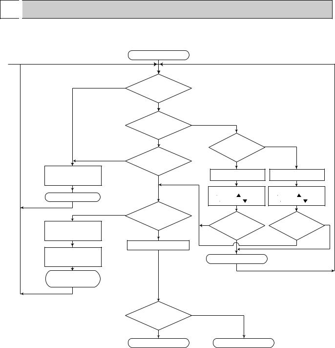
8 
 OPERATION FLOW-CHART
Models : PL-KJB.UK 1. Main operation
|
Start |
|
|
|
|
|
|
|
1 |
|
|
|
|
|
|
|
|
NO |
POWER SUPPLY |
|
|
|
|
|
|
|
|
|
|
|
|
|
|
|
|
|
Live |
|
|
|
|
|
|
|
|
YES |
|
|
|
|
|
|
|
|
<Note 1> |
|
|
|
|
|
|
|
|
TIMER MODE |
|
YES |
|
|
|
|
|
|
button ON |
|
|
|
|
|
|
|
|
NO |
|
|
During |
NO |
|
|
|
|
<Note 2> |
|
|
|
||||
|
|
operation |
|
|
|
|||
|
|
|
|
|
|
|
||
NO |
ON/OFF |
|
|
YES |
|
|
|
|
|
button ON |
|
|
|
|
|
||
Protection device |
|
|
AUTO STOP lamp ON |
AUTO START lamp ON |
||||
Self hold reset |
YES |
|
||||||
|
|
|
|
|
|
|
||
|
|
|
Auto stop timer |
Auto start timer |
||||
STOP |
<Note 3> |
1 |
12Hr up/ |
press |
1 |
12Hr up/ |
press |
|
|
12 1Hr down/ |
press |
12 1Hr down/ |
press |
||||
|
|
|
||||||
YES |
Abnormal |
|
|
|
|
|
|
|
|
operation mode |
|
NO |
Set time - |
|
|
Set time - |
NO |
|
|
|
|
|
||||
Protection device |
|
|
|
|
|
|||
NO |
|
|
Elapsed time=0 |
|
Elapsed time=0 |
|||
Self hold |
|
|
|
|
|
|
|
|
|
POWER lamp ON |
|
|
YES |
|
YES |
||
|
|
|
|
|
|
|
|
|
Self-diagnostic function |
|
|
|
|
|
|
|
|
Indicate & Memory |
|
|
|
STOP |
|
|
|
|
EMERGENCY |
|
|
|
|
|
|
|
|
ALL STOP |
|
|
|
|
|
|
|
|
<Note 4> |
|
|
|
|
|
|
|
|
<Note 5> |
|
|
|
|
|
|
|
|
|
MODE SELECT |
DRY |
|
|
|
|
|
|
|
|
|
|
|
|
|
|
|
|
button |
|
|
|
|
|
|
|
|
COOL |
|
|
|
|
|
|
|
|
COOL OPERATION |
|
|
DRY OPERATION |
|
|
||
Note 1. Refer to page 21~22 for timer mode details.
Note 2. The unit starts operation by pressing the ON / OFF switch when unit is OFF. During operation, the unit stops operation by pressing the ON / OFF switch.
In addition, operation can be turned ON / OFF with the contralized remote controller or the remote switch. Note 3. The factors which cause "abnormal operation mode" are as follows.
●Outdoor unit abnormal operation.
●Fault of room temperature thermistor (RT1). ●Fault of indoor coil thermistor (RT2). ●Indoor coil frost protection mode.
●Drain water overflow prevention mode.
Refer to page 25 for abnormal operation mode details.
Note 4. The indoor fan runs on the low speed for 1 minute to eliminate remaining heat. Note 5. The compressor will not start for 3 minutes after the stop.
14
 Loading...